

Page 1
Prime™ Series Stretcher
1115
Big Wheel
Operations Manual
For parts or technical assistance call:
USA: 1-800-327-0770
2012/09 D.3 1115 -109 - 0 01 R EV D www.stryker.com
Page 2

Page 3

Table of Contents
Symbols and Definitions ....................................................................5
Symbols ............................................................................5
Warning/Caution/Note Definition ...........................................................6
Introduction .............................................................................7
Product Description ....................................................................7
Intended Use of Product.................................................................7
Intended Use of Product - Prime X Option ...................................................7
Specifications ........................................................................9
Specifications - Optional Scale System (Non-Electric Litter/Electric Litter Option) .....................11
Product Illustration - Electric Litter Option...................................................12
Product Illustration - Prime X Option.......................................................13
Contact Information ...................................................................14
Serial Number Location ................................................................14
Summary of Safety Precautions .............................................................15
Setup Procedures........................................................................20
Operation Guide.........................................................................21
Applying the Brake System..............................................................21
Operating the Base Controls - Side Control Hydraulics .........................................22
Operating the Base Controls - Optional Three-Sided and Four-sided Control Hydraulics.................23
Raising and Lowering the Litter Height - Optional Electric Lift ....................................24
Adjusting Trendelenburg/Reverse Trendelenburg Positions - Side Control Hydraulics ...................25
Adjusting Trendelenburg/Reverse Trendelenburg Positions - Optional Three-Sided or Four-Sided Control Hydraulics 25
Operating the Big Wheel®..............................................................26
Operating the Siderails.................................................................27
Operating the Siderail Patient Controls - Optional Electric Litter (Not Available With Prime X Option) .......28
Operating the Foot End Nursing Controls - Optional Electric Litter (Not Available With Prime X Option)......29
Using Patient Control Lockout - Optional Electric Litter (Not Available With Prime X Option)..............30
Operating the Optional Push Handles......................................................30
Operating the Pneumatic Fowler - Non-Electric...............................................31
Operating the Fowler - Optional Electric Litter (Not Available With Prime X Option) ....................32
Operating the Optional Gatch - Non-Electric (Not Available With Prime X Option)......................33
Operating the Gatch - Optional Electric Litter (Not Available With Prime X Option).....................34
Operating the Recovery Chair (Not Available With Prime X Option) ................................35
Using the Base Hood for Storage .........................................................36
Using the Optional Pump Rack...........................................................37
Using the Optional Retractable Cord Reel - Electric Lift/Litter Option...............................38
Operating the Optional Scale System......................................................39
Operating the Optional Scale System - Non-Electric Litter.......................................40
Replacing the Optional Scale System Batteries - Non-Electric Litter ...............................41
Operating the Optional Scale System - Electric Litter Option Without Chaperone (Not Available With Prime X Option) 42
Charging the Optional Scale System Battery Pack - Electric Litter Option (Not Available With Prime X Option) 43
Operating the Optional Scale System - Electric Litter Option With Chaperone (Not Available With Prime X Option) 44
www.stryker.com 1115 -10 9 - 0 01 R EV D 3
Page 4

Table of Contents
Operating the Chaperone (Stretcher Exit) Option (Not Available With Prime X Option) ..................45
Charging the Optional Scale System Battery Pack - Electric Litter Option with Chaperone (Not Available With
Prime X Option) ......................................................................45
Operating the Chaperone (Stretcher Exit) Option - Optional Setup (Not Available With Prime X Option) .....46
Using X-Ray Cassettes - Prime X Option ...................................................47
Using the Defibrillator Tray ..............................................................48
Using the Foot Extension/Defibrillator Tray ..................................................48
Using the Footboard/Chartholder .........................................................49
Using the I.V. Caddy ...................................................................49
Operating the Foot Supports (Not Available With Prime X Option) .................................50
Operating the Two-Stage Permanently Attached I.V. Pole .......................................52
Operating the Three-Stage Permanently Attached I.V. Pole .....................................53
Operating the Removable I.V. Pole ........................................................54
Installing the Siderail Pads ..............................................................54
Using the Upright Oxygen Bottle Holder ....................................................55
Using the Serving Tray .................................................................55
Using the Restraint Straps ..............................................................56
Using the Upright X-Ray Cassette Holder ...................................................57
Using the Lateral Cassette Holder ........................................................58
Cleaning...............................................................................59
Stretcher Cleaning....................................................................59
Mattress Cleaning ....................................................................60
Preventative Maintenance ..................................................................62
Checklist ..........................................................................62
Preventative Maintenance ..................................................................63
Checklist (Continued)..................................................................63
EMC Information.........................................................................64
Optional Electric Lift/Litter and Optional Scale System .........................................64
Warranty ..............................................................................68
Limited Warranty .....................................................................68
To Obtain Parts and Service ............................................................68
Service Contract Coverage .............................................................68
Service Contract Programs .............................................................69
Return Authorization...................................................................69
Damaged Merchandise ................................................................69
International Warranty Clause............................................................69
Recycling Passport ......................................................................70
4 1115 -10 9 - 0 01 R EV D www.stryker.com
Page 5
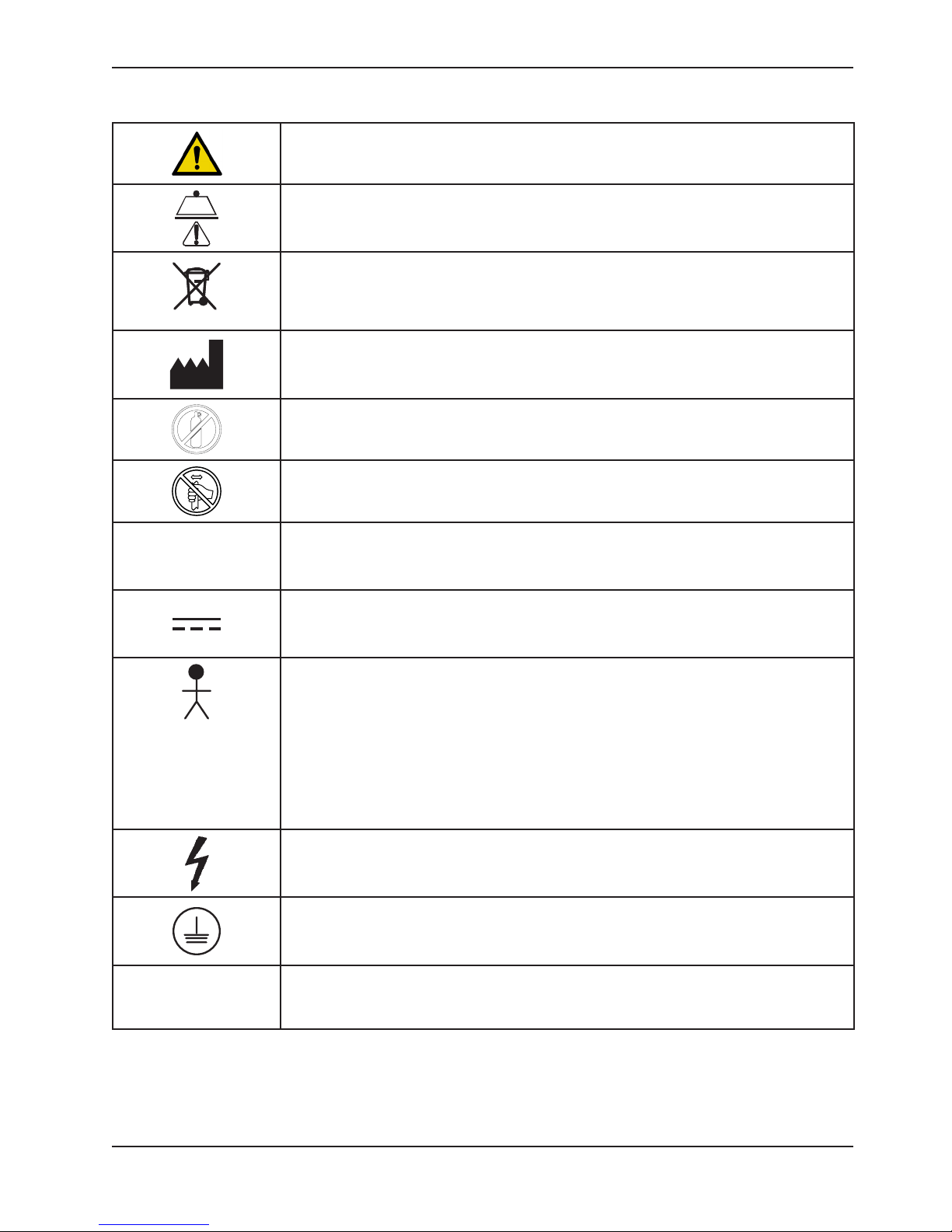
SYMBOLS
~
Symbols and Definitions
Warning/Caution: Consult accompanying documentation
Safe Working Load indicates the sum of the patient, mattress, and accessory weight
In accordance with European Directive 2002/96/EC on Waste Electrical and Electronic
Equipment, this symbol indicates that the product must not be disposed of as unsorted
municipal waste, but should be collected separately. Refer to your local distributor for
return and/or collection systems available in your country.
Manufacturer
Do not store oxygen bottle
Do not push/pull
IPX6
Alternating Current
Direct Current
Type B Equipment: equipment providing a particular degree of protection against electric
shock, particularly regarding allowable leakage current and reliability of the protective
earth connection.
Class 1 Equipment: equipment in which protection against electric shock does not rely on
basic insulation only, but which includes an additional safety precaution in that means are
provided for the connection of the equipment to the protective earth conductor in the fixed
wiring of the installation in such a way that accessible metal parts cannot become live in
the event of a failure of the basic insulation.
Dangerous Voltage
Protective Earth Terminal
Protection from Liquid Jet
www.stryker.com 1115 -10 9 - 0 01 R EV D 5
Return To Table of Contents
Page 6
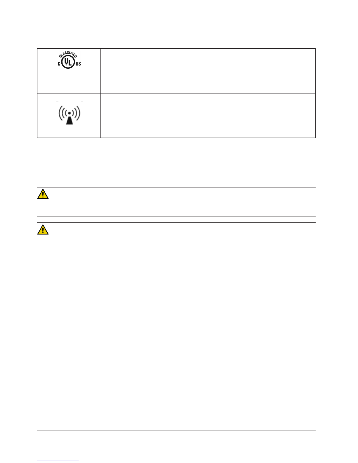
Symbols and Definitions
Medical Equipment Classified by Underwriters Laboratories Inc. with Respect to Electric
Shock, Fire, Mechanical and Other Specified Hazards Only in Accordance with UL
87VL
MEDICAL
ELECTR ICAL
EQUIPMENT
UL 60601-1
CAN/CSA C 22.2
N0. 601.1
*IEC 60601-
2-32:1994
WARNING/CAUTION/NOTE DEFINITION
The words WARNING, CAUTION and NOTE carry special meanings and should be carefully reviewed.
60601-1 First Edition (2003) and CAN/CSA C22.2 No. 601.1.
*For Prime-X Option, Associated Equipment of X-Ray Equipment IEC 60601-2-32:1994
Non-Ionizing Radiation
WARNING
Alerts the reader about a situation which, if not avoided, could result in death or serious injury. It may also describe
potential serious adverse reactions and safety hazards.
CAUTION
Alerts the reader of a potentially hazardous situation which, if not avoided, may result in minor or moderate injury to the
user or patient or damage to the equipment or other property. This includes special care necessary for the safe and
effective use of the device and the care necessary to avoid damage to a device that may occur as a result of use or
misuse.
NOTE
Provides special information to make maintenance easier or important instructions clearer.
Return To Table of Contents
6 1115 -10 9 - 0 01 R EV D www.stryker.com
Page 7

Introduction
This manual is designed to assist you with the operation of Stryker Model 1115 Prime Series Stretcher. Read this
manual thoroughly before using the equipment or beginning maintenance on it. To ensure safe operation of this
equipment, it is recommended that methods and procedures be established for educating and training staff on the safe
operation of this stretcher.
PRODUCT DESCRIPTION
The Stryker Model 1115 Prime Series Stretcher with Big Wheel® decreases start-up force by 50 percent and steering
effort by 60 percent.
INTENDED USE OF PRODUCT
The Stryker Model 1115 Prime Series Stretcher is a wheeled device which consists of a platform mounted on a wheeled
frame that is designed to support patients in a horizontal position. The device has siderails and has the option available
to support the temporary or permanent placement of I.V. poles. A stretcher provides the caregiver a method of
transporting patients within a healthcare facility. The device has a two Big Wheels which reduces the required start-up
force to move the stretcher. Some stretchers may also be used for minor procedures and short-term stay (treatment
and recovery).
INTENDED USE OF PRODUCT - PRIME X OPTION
The Prime X option provides a platform for the short-term outpatient clinical evaluation and treatment of human patients
and additionally may be used for minor procedures and short-term outpatient stay (treatment and recovery). The Prime
X option provides an articulating radiographic patient support surface and a platform below the patient support surface
for X-Ray cassette placement to allow the capture of clinical X-Rays (AP Full Body, optional Full Body Lateral, and
optional Upright Chest) when used in conjunction with a medical X-Ray system. The Prime X option is a wheeled device
consisting of a platform mounted on a wheeled frame that is designed to transport patients in a horizontal position
within the interior of a healthcare facility by health professionals and/or trained representatives of the user facility. The
device has siderails and optional supports for fluid infusion equipment.
The Prime X option is intended to be used to transport patients to and from all departments within the interior of a
healthcare facility. The use of the Prime X option as a short-term outpatient clinical evaluation, treatment, minor
procedure, and short-term outpatient recovery platform may include use in, but not limited to, the Emergency Department
(ED), including the Trauma area, and Post-Anesthesia Care Unit (PACU). The Prime X option is not intended to be used
for long-term inpatient treatment and recovery. See the specification table in the operations manual of the device for
the intended environmental conditions.
The Prime X option has a safe working load up to 700 pounds (318 kg) and is intended to be used with all patients,
including those mildly to critically ill. The stretcher may also be used to transport deceased patients within an enclosed
healthcare facility.
The Prime X option has an optional scale system intended to measure and display weight in pounds or kilograms of
patients weighing 50 to 700 pounds (22.7 to 318 kg) and patients not exceeding the height of 75.25 inches (191 cm).
See the specification table for accuracy claims.
The Prime X option has an expected life of 10 years under normal use, conditions, and with appropriate periodic
maintenance as described in the maintenance manual for each device.
The Prime X option is not recommended for use with a Stryker Pioneer mattress or a mattress with a thickness
greater than four inches and is not compatible for use with a C-Arm. The Prime X option is intended for use in all
establishments other than home healthcare, domestic, and those directly connected to the public low voltage power
supply network that supplies buildings used for domestic purposes.
www.stryker.com 1115 -10 9 - 0 01 R EV D 7
Return To Table of Contents
Page 8

IntroductionIntroduction
INTENDED USE OF PRODUCT - PRIME X OPTION (CONTINUED)
The Prime X option has the following options available: three-sided brake/steer pedal controls, three-sided and foursided hydraulic lift controls, powered lift controls, dual siderail latch assembly, slider board assembly, pump bar, I.V.
pole(s), restraint straps, defibrillator tray, defibrillator tray/foot extender, footboard/chartholder, serving tray, serving tray
holder/footboard, siderail pads, upright oxygen bottle holder, and I.V. caddy and may include other options as described
in the operations manual.
Return To Table of Contents
8 1115 -10 9 - 0 01 R EV D www.stryker.com
Page 9

SPECIFICATIONS
IntroductionIntroduction
26” Width 30” Width Option
Safe Working Load
Note: Safe Working
Load indicates the sum
of the patient, mattress,
and accessory weight.
Overall Stretcher Length 85” (± .5”) 215.9 cm 85” (± .5”) 215.9 cm 85” (± .5”) 215.9 cm
Overall Stretcher Width
(Siderails Up)
Overall Stretcher Width
(Siderails Down)
Minimum/Maximum
Stretcher Height
Fowler Angle 0° to 90° (± 5°)
Gatch Height 5.5” (14 cm) minimum Not applicable
Trendelenburg/Reverse
Trendelenburg
Minimum UnderStretcher Clearance
Attenuation Equivalent
(Aluminum Equivalence)
700 lb 318 kg 700 lb 318 kg 700 lb 318 kg
34” (± 1”) 86.4 cm 38” (± 1”) 96.5 cm 38” (± 1”) 96.5 cm
30.25”
(± .5”)
20.75” /
34” (± 1”)
+17°/-17° (± 3 °)
2.5”
nominal
1.75”
under the
hydraulic
jacks and
fifth wheel
1” under
the Big
Wheel
Not applicable
76.8 cm
52.7 cm /
86.4 cm
6.4 cm
4.5 cm
2.5 cm
30.5”
(± .5”)
20.75” /
34” (± 1”)
2.5”
nominal
1.75”
under the
hydraulic
jacks and
fifth wheel
1” under
the Big
Wheel
77.5 cm
52.7 cm /
86.4 cm
6.4 cm
4.5 cm
2.5 cm
Prime X Option
30” Width
30.5”
(± .5”)
23.25” /
36.5” (± 1”)
2.5”
nominal
1.75”
under the
hydraulic
jacks and
fifth wheel
1” under
the Big
Wheel
Maximum Value
Allowed is 1.7 mm Al
77.5 cm
59.1 cm /
92.7 cm
6.4 cm
4.5 cm
2.5 cm
www.stryker.com 1115 -10 9 - 0 01 R EV D 9
Return To Table of Contents
Page 10

IntroductionIntroduction
SPECIFICATIONS (CONTINUED)
Electric Options Optional Electric Litter Optional Electric Lift
Electrical Requirements
Duty Cycle
Optional Scale System Non-Electric Litter Optional Electric Lift
Bat tery Type
Battery Voltage
Optional Scale System Optional Electric Litter Optional Electric Lift
Bat tery Type
Battery Voltage
Optional Scale System with
Chaperone (Stretcher Exit)
Bat tery Type
Battery Voltage
120V~, 60Hz, 10 A 120V~, 60Hz, 10 A
Continuous operation with intermittent loading is 1
min ON/20 min OFF
4 x AA Battery (4 X 1.5V ) Alkaline Type (LR6)
6.0V 6.0V
1 x Rechargeable Lithium Ion
Battery Pack (0058-135-000)
10.8V , 2.4Ah
Optional Electric Litter Optional Electric Lift
1 x Rechargeable Lithium Ion
Battery Pack (0058-134-000)
10.8V , 4.8Ah
Continuous operation
with intermittent loading
is 1 min ON/20 min OFF
4 x AA Battery (4 X 1.5V
) Alkaline Type (LR6)
Not applicable
Not applicable
Not applicable
Not applicable
Stryker reserves the right to change specifications without notice.
Note: Equipment not suitable for use in the presence of a flammable anesthetic mixture with air or with oxygen or
nitrous oxide.
Return To Table of Contents
10 1115 -10 9 - 0 01 R EV D www.stryker.com
Page 11

SPECIFICATIONS (CONTINUED)
Environmental Conditions Operation Storage and Transportation
IntroductionIntroduction
Temperature
0
50 F
0
(10 C)
0
100 F
0
(38 C)
75%
0
-4 F
0
(-20 C)
140 F
0
(60 C)
95%
0
Relative Humidity
30%
106 0 h Pa
10%
106 0 h Pa
Atmospheric Pressure
700 hPa
500 hPa
Specifications listed are approximate and may vary slightly from unit to unit or by power supply fluctuations.
SPECIFICATIONS - OPTIONAL SCALE SYSTEM (NON-ELECTRIC LITTER/ELECTRIC LITTER OPTION)
Optional Scale System Weight Operating Range 50 lb (22.7 kg) to 700 lb (318 kg)
Optional Scale System Accuracy
±3 lb (1.3 kg) for weights less than 100 lb (45 kg) and ±3% for
weights greater than or equal to 100 lb (45 kg) *
Environmental Conditions Operation Storage and Transportation
Temperature
0
61 F
0
(16 C)
0
79 F
0
(26 C)
75%
0
-4 F
0
(-20 C)
0
140 F
0
(60 C)
95%
Relative Humidity
30%
106 0 h Pa
10%
106 0 h Pa
Atmospheric Pressure
700 hPa
500 hPa
* To meet this accuracy claim, the patient surface must be in the flat position (fowler and gatch down) and the
stretcher cannot exceed 5 degrees of Trendelenburg/reverse Trendelenburg.
www.stryker.com 1115 -10 9 - 0 01 R EV D 11
Return To Table of Contents
Page 12
IntroductionIntroduction
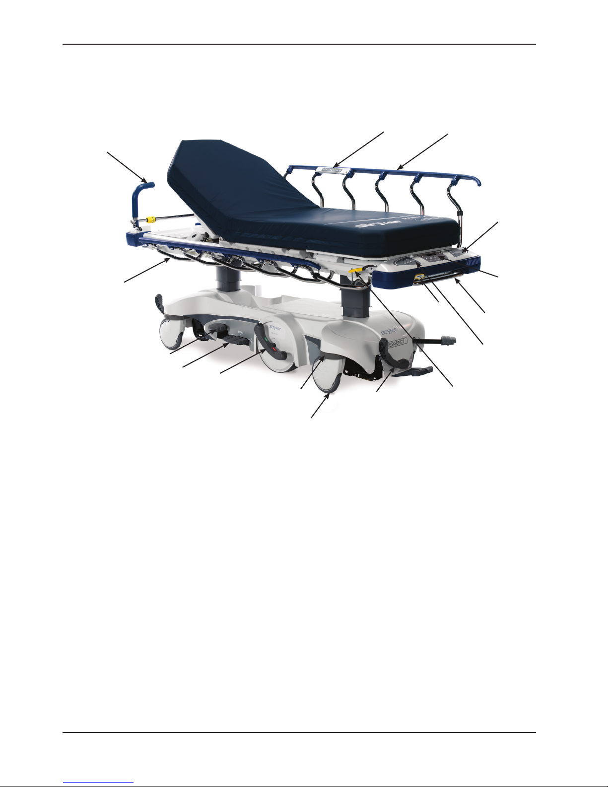
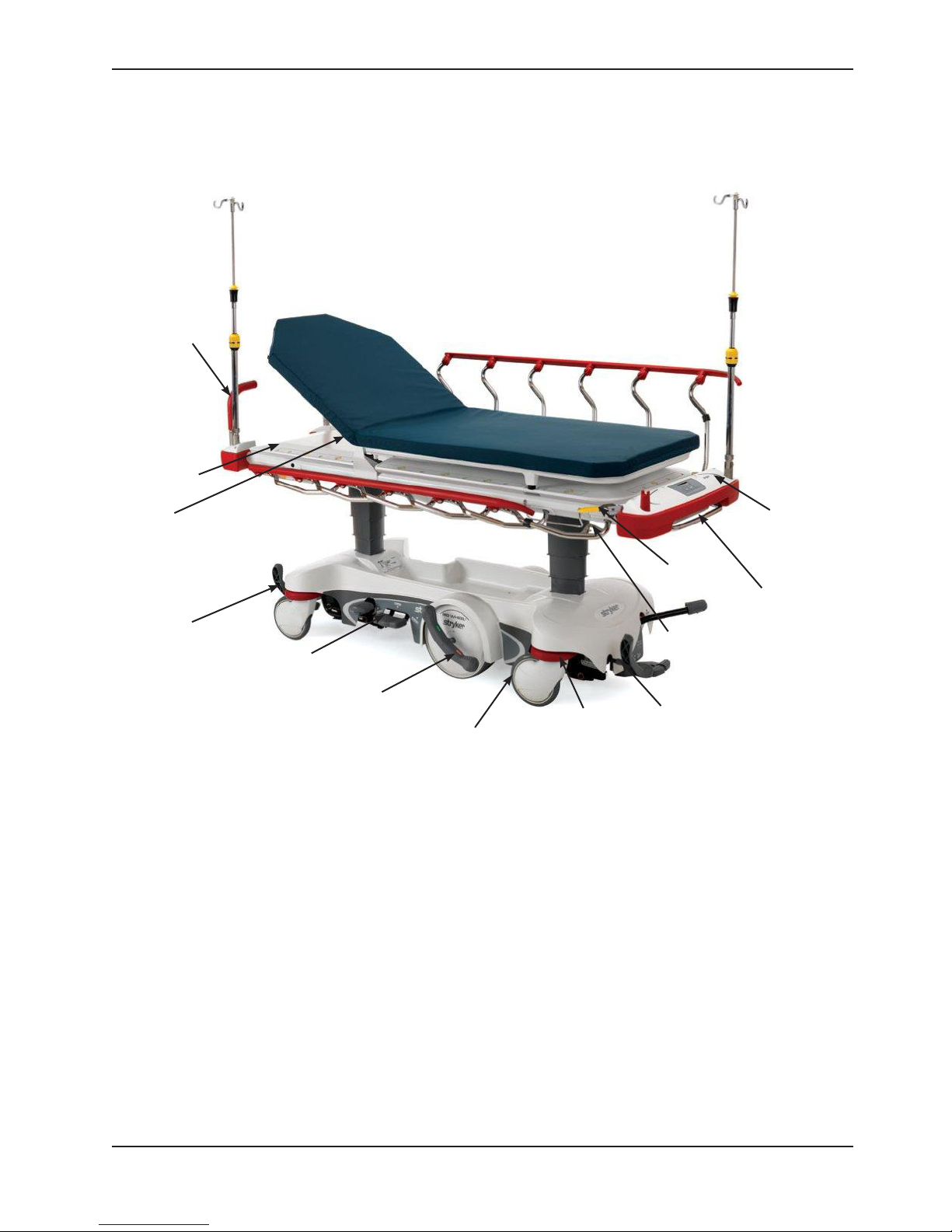
PRODUCT ILLUSTRATION - ELECTRIC LITTER OPTION
Optional
Pop Up Push
Handle
Siderail
Push Pedal
Uni-Lower
Pedal
Brake/Steer
Control Pedal
Option
Integrated
Bumpers
Casters with
Integrated
Wheel Covers
Optional Siderail
Patient Controls
Gatch Release
Brake/Steer
Control Pedal
Optional
Handle
Siderail
Release
Siderail
Optional Patient
Control Lockout
Optional
Scale
System
Optional
Pump Rack
Optional Foot
End Nursing
Controls
Figure 1: Electric Litter Option
Return To Table of Contents
12 1115 -10 9 - 0 01 R E V D www.stryker.com
Page 13
IntroductionIntroduction
PRODUCT ILLUSTRATION - PRIME X OPTION
Optional
Pop Up Push
Handle
Cassette Tray
Patient
Surface with
Clear View
Technology
Pump Pedal
Uni-Lower
Pedal
Control Pedal
Brake/Steer
Option
Casters with
Integrated
Wheel Covers
Figure 2: Prime X Option
Integrated
Bumpers
Siderail
Release
Siderail
Brake/Steer
Control Pedal
Optional
Scale System
Optional
Pump Rack
www.stryker.com 1115 -10 9 - 0 01 R EV D 13
Return To Table of Contents
Page 14
Introduction
CONTACT INFORMATION
Contact Stryker Customer Service or Technical Support at: (800) 327-0770 or (269) 324-6500.
Stryker Medical
3800 E. Centre Avenue
Portage, MI 49002
USA
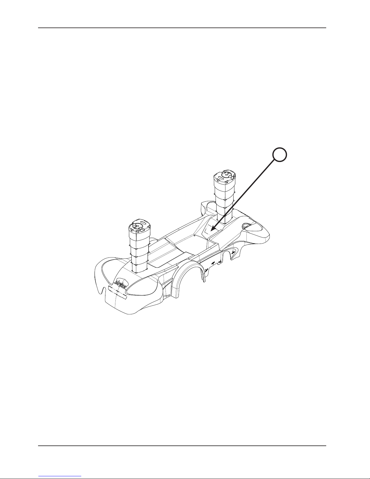
Please have the serial number (A) of your Stryker product available when calling Stryker Customer Service or Technical
Support. Include the serial number in all written communication.
SERIAL NUMBER LOCATION
A
Return To Table of Contents
14 1115 -10 9- 00 1 R E V D www.stryker.com
Figure 3: Serial Number Loction
Page 15

Summary of Safety Precautions
Carefully read and strictly follow the warnings and cautions listed on this page. Service only by qualified personnel.
See the maintenance manual for additional information.
WARNING
• This stretcher is equipped with a hospital grade plug for protection against electric shock hazard. It must be
plugged directly into a properly grounded three-prong receptacle. Grounding reliability can be achieved only when
a hospital grade receptacle is used.
• Always apply the brakes when a patient is getting on or off the stretcher. Push on the stretcher to ensure that the
brakes are securely locked. Always engage the brakes unless the stretcher is being moved. Injury could result if
the stretcher moves while a patient is getting on or off the stretcher.
• Patients should be discouraged from sitting directly on the ends of the stretcher. Excessive weight could cause
the litter surface to tip up, possibly causing patient injury.
• Leave the stretcher height in the lowest position when the patient is left unattended. Leaving the stretcher height
in a raised position could increase the chance of patient falls and injury.
• Make sure that the brakes are completely released before attempting to move the unit. Attempting to move the unit
with the brakes engaged could result in injury to the user and/or patient.
• After raising the siderails, pull firmly on the siderail to ensure that it is securely locked into the up position. Siderails
are not intended to serve as a patient restraint device to keep patients from exiting the unit. Siderails are intended
to keep a patient from inadvertently rolling off the unit. It is the responsibility of the attending medical personnel
to determine the degree of restraint necessary to ensure that a patient will remain in place. Failure to utilize the
siderails properly could result in patient injury.
• When lowering the siderail to the collapsed position, keep extremities of patients and staff away from the siderail
spindles or injury could occur.
• Powered stretcher mechanisms can cause serious injury. Operate stretcher only with persons clear of mechanisms.
• Operation of the fowler is a manual procedure. Use caution when raising the fowler while a patient is on the
stretcher. Use proper lifting techniques and get additional assistance, if necessary. Failure to use proper lifting
techniques could cause injury to the operator.
• Keep hands/fingers clear of the area around the fowler release handle and the fowler frame when lowering the
fowler. Injury could result if care is not taken when lowering the fowler.
• To avoid the risk of injury, ensure that the gatch prop rod is fully raised and securely placed into position.
• Use caution when operating the gatch while a patient is on the stretcher. Powered stretcher mechanisms can
cause serious injury. Operate stretcher only with persons clear of mechanisms.
• Use caution when operating the recovery chair while a patient is on the stretcher. Powered stretcher mechanisms
can cause serious injury. Operate stretcher only with persons clear of mechanisms.
• To avoid patient injury or equipment damage, all lines from any equipment stored on the pump rack must be
diverted away from the gatch handles.
• To avoid patient injury or equipment damage, do not lift the stretcher by the pump rack.
• To avoid equipment damage, remove any equipment from the pump rack that may be in the way before lowering
the litter.
• To avoid equipment damage while transporting the stretcher, verify that any equipment on the pump rack can
safely pass through door openings and under light fixtures.
• When using the Prime X option in conjunction with devices that generate X-radiation, the generating devices may
produce residual, stray, and/or scattered radiation. Users should refer to local, state, and federal use guidelines
as well as appropriate facility protocols for safety before use. Special attention should be given when performing
X-Rays with the stretcher’s fowler in the upright position and also when performing X-Rays using a lateral cassette.
www.stryker.com 1115 -10 9 - 0 01 R EV D 15
Return To Table of Contents
Page 16

Summary of Safety Precautions
WARNING (CONTINUED)
• The Prime X option is not recommended for use with a Stryker Pioneer mattress or a mattress with a thickness
greater than four inches and is not compatible for use with a C-Arm.
• To avoid the risk of injury to the patient or user or damage to the I.V. pole while transporting the stretcher, make
sure that the I.V. caddy is securely tightened on the I.V. pole.
• To avoid the risk of patient injury or equipment damage, do not sit on the foot support.
• Physical restraints, even if properly secured, may result in serious harm to patients and caregivers. The use of
restraint straps may potentially cause entanglement, entrapment, physical injury, and/or death. Caution must be
used in affixing restraint straps to avoid potential injury to both patients and caregivers.
• Restraint straps and/or devices must be attached only at the identified attachment points of the unit. Failure to do
so may result in patient or caregiver injury. Do not attach restraints straps to the siderail.
• This unit accommodates the use of ankle, chest, wrist, and body restraints. The use of restraint straps is regulated
by state and federal restrictions. Users, caregivers, and/or practitioners should refer to the applicable state and
federal restrictions and the appropriate facility protocols before using any restraint strap and/or device.
• If your unit is equipped with the optional electric lift/litter, unplug the power cord from the power outlet before
transporting or cleaning the unit. To unplug, grasp the mold near the outlet and pull the cord in a direction parallel
to the floor (not at an angle).
• This device does not offer any protection against X-Ray radiation.
• Do not steam clean the unit.
• Medical electrical equipment (such as the optional scale system or optional electric lift/litter) requires special
precautions regarding EMC and needs to be installed and put into service according to the EMC information
provided on page 64 to prevent equipment malfunction.
• Portable and mobile RF communication equipment can affect Medical Electrical Equipment (such as the optional
scale system or optional electric lift/litter).
• To avoid malfunction, the optional scale system or optional electric lift/litter should not be used adjacent to or
stacked with other equipment. If adjacent or stacked use is necessary, the optional scale system or optional
electric lift/litter should be observed to verify normal operation in the configuration in which it will be used.
• When using any mattress thicker than 2.5 inches or when using a mattress overlay with the Prime X option, extra
caution and operator supervision is recommended to reduce the risk of patient falls due to lesser siderail coverage.
CAUTION
• This stretcher is not intended for pediatric use or for patients under 50 lb. This stretcher is intended for use by
trained hospital personnel only.
• Do not modify this stretcher. Modifying the unit can cause unpredictable operation resulting in injury to the patient
or operator. Modifying the unit will also void its warranty.
• To avoid damage, remove any equipment that may be in the way before raising or lowering the litter height.
• Do not raise the unit (hydraulics on base) with a patient lift under the stretcher.
• To avoid injury or damage to the equipment, do not allow the siderail to lower on its own.
• The weight capacity of the gatch is 200 lb. Do not sit or stand on the gatch. Injury or damage to the equipment
could occur.
• To achieve recovery chair position, your stretcher must be equipped with the lift assist backrest and gatch options.
• The weight capacity of the base hood is 60 lb. Do not sit or stand on the base hood. Injury or damage to the
equipment could occur.
• Do not step on the base hood.
• Do not engage the steer pedal when the Big Wheel is resting on a threshold or other raised area. The force
required to engage the Big Wheel will be higher than normal, possibly causing damage.
• Do not use the cutout for the oxygen bottle holder on the base hood for the storage of oxygen bottles or patient
belongings.
Return To Table of Contents
16 1115 -10 9 - 0 01 R EV D www.stryker.com
Page 17

Summary of Safety Precautions
CAUTION (CONTINUED)
• The weight capacity of the pump rack is 40 lb.
• Do not use the pump rack as a push/pull device, because equipment damage could occur.
• To avoid damage, do not put items weighing more than 30 lb on the defibrillator tray.
• To avoid risk of patient or operator injury, ensure that all devices placed on the defibrillator tray are securely
strapped to the tray.
• Do not use the defibrillator tray as a push/pull device, because equipment damage could occur.
• If the stretcher is equipped with the optional foot end I.V. pole, the I.V. pole must be in the raised position when the
foot extension/defibrillator tray is installed. If the I.V. pole is not raised, the foot extension will not function properly
and injury could occur.
• The push handles were designed for use while transporting the stretcher. Avoid using other parts of the stretcher
as push/pull devices because damage could occur.
• To avoid damage, do not put items weighing more than 30 lb on the foot extender/defibrillator tray.
• Do not use the foot extension/defibrillator tray as a push/pull device, because equipment damage could occur.
• Do not use the footboard/chartholder as a push/pull device because equipment damage could occur.
• Always store the I.V. caddy when not in use to avoid damaging it when the unit is moved.
• To avoid the risk of equipment damage, do not use the foot support to store patient belongings or other items.
• To avoid injury to the operator, ensure that the operator’s fingers are clear of the mechanism when positioning the
foot support.
• Foot supports should be in the stored position when moving. The stretcher should be in brake position when foot
supports are in use.
• To avoid the risk of damage to the equipment, do not use the foot support as a push/pull device.
• To avoid injury to the patient or operator, ensure foot supports are tightened securely prior to use.
• If the stretcher is equipped with the scale system option, the scale should not be utilized while the foot supports
are in use because inaccurate readings may occur.
• If the stretcher is equipped with the chaperone option, the chaperone option should not be utilized while the foot
supports are in use because false readings may occur.
• To avoid damage to the removable I.V. pole, the weight of the I.V. bags should not exceed 40 lb.
• To avoid damage, the safe working load of the two-stage permanently attached I.V. pole is 40 lb.
• To avoid damage while transporting the stretcher, verify that the I.V. pole is at a low enough height to allow it to
safely pass through door openings and under light fixtures.
• Do not use the I.V. pole as a push/pull device because equipment damage could occur.
• To avoid damage, the weight of the I.V. bags should not exceed 12 lb while the weight of any one item attached to
each stage of the three-stage permanently attached I.V. pole should not exceed 9.3 lb.
• To avoid damage, do not put items weighing more than 40 lb in the upright oxygen bottle holder.
• Do not use the upright oxygen bottle holder as a push/pull device because equipment damage could occur.
• To avoid damage, do not put items weighing more than 30 lb on the serving tray.
• To avoid risk of user injury or damage to the equipment, ensure that the Upright X-Ray Cassette Holder is installed
correctly, following the instructions below.
• To avoid risk of user injury or damage to the equipment, ensure that the Lateral X-Ray Cassette Holder is installed
correctly, following the instructions below.
• Do not use the serving tray holder/footboard as a push/pull device because equipment damage could occur.
• Before returning the unit to service after cleaning, ensure that the unit is functioning properly by verifying that all
labels are intact, raise/lower the stretcher height, brake/steer pedal locks properly in both positions, latch/unlatch
the siderails, and raise/lower the fowler and gatch.
www.stryker.com 1115 -10 9 - 0 01 R EV D 17
Return To Table of Contents
Page 18

Summary of Safety Precautions
• Some cleaning products are corrosive in nature and may cause damage to the product if used improperly. If the
products suggested above are used to clean Stryker patient handling equipment, measures must be taken to ensure
that the stretcher is wiped with a damp cloth soaked in clean water and thoroughly dried following cleaning. Failure
to properly rinse and dry the stretcher will leave a corrosive residue on the surface of the stretcher, possibly causing
premature corrosion of critical components. Failure to follow the directions provided in the Cleaning section of this
manual (page 60) when using these types of cleaners may void this product’s warranty.
NOTE
• Equipment not suitable for use in the presence of a flammable anesthetic mixture with air or with oxygen or nitrous
oxide.
• The bottom of the brake pads should be cleaned regularly to prevent wax or floor remnant buildup.
• Clean the base hood storage area regularly.
• In lieu of specific requirments from IEC 60601-1 and IEC 60601-2-32:1994, equivalent means of safety were used
on the Prime-X series of products regarding accessory overloading, applied parts, and indications to the operator.
Return To Table of Contents
18 1115 -10 9 - 0 01 R EV D www.stryker.com
Page 19
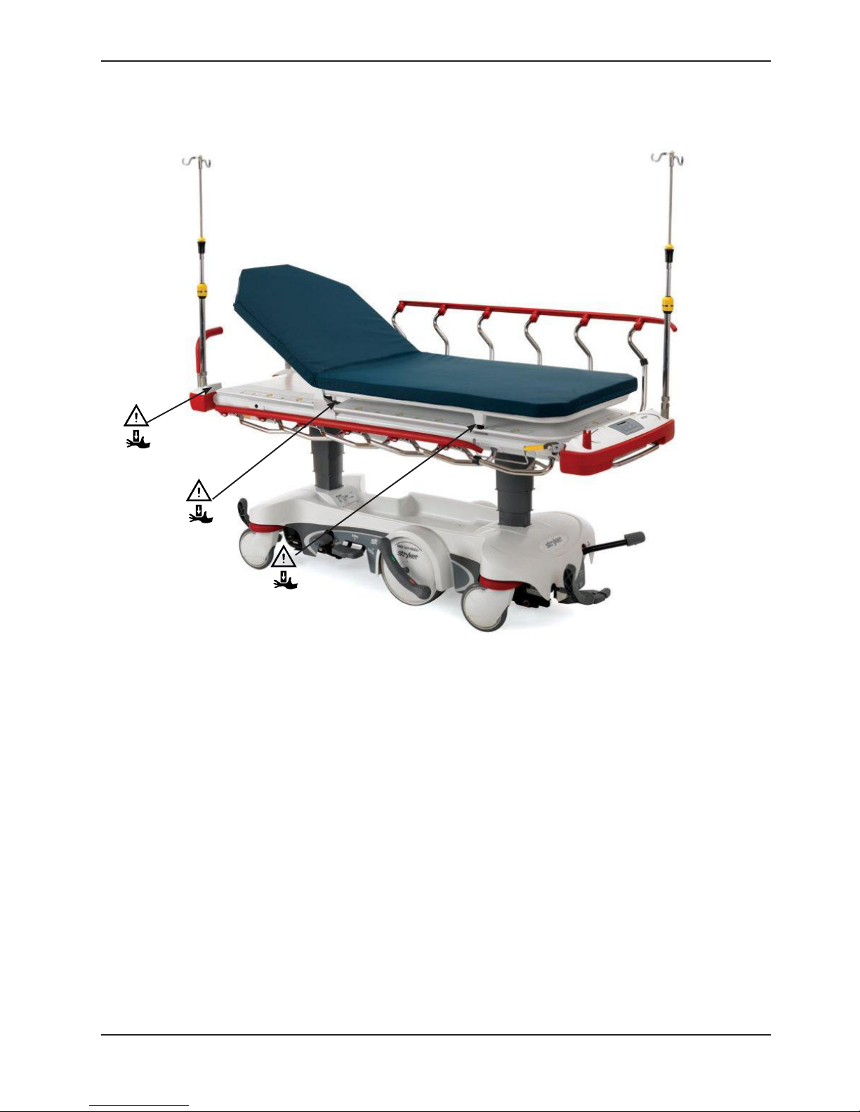
Summary of Safety Precautions
PINCH POINTS - PRIME X OPTION
Figure 4: Pinch Points - Prime X Option
Return To Table of Contents
www.stryker.com 1115 -10 9 - 0 01 R EV D 19
Page 20

Setup Procedures
If this unit is equipped with the optional electric lift/litter, the unit must reach room temperature prior to conducting
any setup and/or unit operations to prevent permanent damage to the unit.
Make sure that the unit is working properly before it is put into service. The following list will ensure that each part of
the unit is checked.
Stretcher checklist:
1. Depress the pedal at either end of the stretcher fully to set the four wheel brakes and verify that all of the four
casters are locked (page 21).
2. Raise and lower the hydraulic lift system (page 22 or page 23).
3. Raise the unit completely and activate the Trendelenburg function. Ensure that the head end lowers to the full
down position (page 25).
4. Raise the unit completely and activate the reverse Trendelenburg function. Ensure the foot end lowers to the full
down position (page 25).
5. Run through the operation of the Big Wheel to ensure that it is operating properly (page 26).
6. Ensure that the siderails raise and lower smoothly and lock securely in the full up position (page 27).
7. Raise and lower the fowler (head end) (page 31).
8. Raise and lower the gatch (foot end) (page 33).
If equipped with the optional electric lift/litter:
1. Check all items on the stretcher checklist above.
2. Plug the unit into a properly grounded, hospital grade wall receptacle and ensure that the LED lights illuminate on
the lockout keypad.
3. Raise and lower the hydraulic lift system (page 24).
4. Perform each function on the patient siderail controls to ensure that they are working properly (page 28).
5. Perform each function on the foot end nursing controls to ensure that they are working properly (page 29).
6. Raise and lower the fowler (head end) (page 32).
7. Raise and lower the gatch (foot end) (page 34).
If equipped with the optional scale - electric litter option (with or without chaperone option):
1. Check all items on the stretcher checklist above.
2. Plug the power cord into a properly grounded, hospital grade wall receptacle to charge the batteries.
Note: To charge the battery, see “Charging the Optional Scale System Battery Pack - Electric Litter Option (Not
Available With Prime X Option)” on page 43 or “Charging the Optional Scale System Battery Pack - Electric
Litter Option with Chaperone (Not Available With Prime X Option)” on page 45.
WARNING
This stretcher is equipped with a hospital grade plug for protection against electric shock hazard. It must be plugged
directly into a properly grounded three-prong receptacle. Grounding reliability can be achieved only when a hospital grade
receptacle is used.
CAUTION
• Do not modify this stretcher. Modifying the unit can cause unpredictable operation resulting in injury to the patient
or operator. Modifying the unit will also void its warranty.
• This stretcher is not intended for pediatric use or for patients under 50 lb. This stretcher is intended for use by
trained hospital personnel only.
Return To Table of Contents
20 1115 -10 9 - 0 01 R EV D www.stryker.com
Page 21
Operation Guide
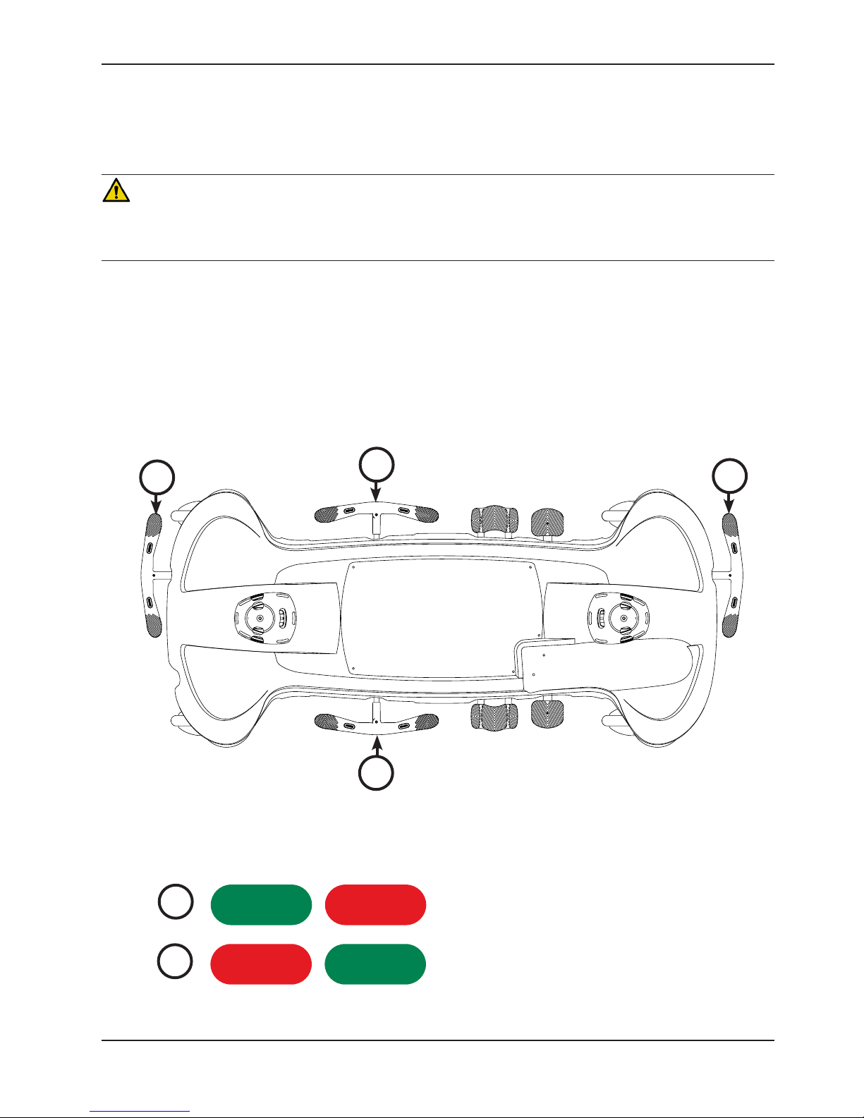
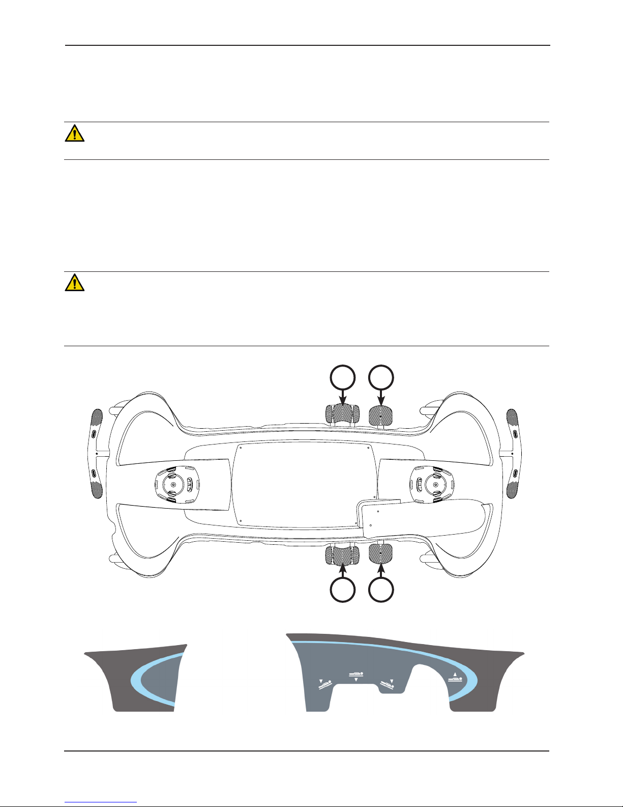
APPLYING THE BRAKE SYSTEM
For user convenience, a brake/steer control pedal is located on both ends of the stretcher as shown in Figure 5.
WARNING
Always apply the brakes when a patient is getting on or off the stretcher. Push on the stretcher to ensure that the brakes
are securely locked. Always engage the brakes unless the stretcher is being moved. Injury could result if the stretcher
moves while a patient is getting on or off the stretcher.
To e ngage the brakes on the head end, push down on the brake (red) side of pedal (A).
To engage the brakes on the foot end, push down on the brake (red) side of pedal (B).
To release the brakes on the head end, push down on the steer (green) side of pedal (A).
To release the brakes on the foot end, push down on the steer (green) side of pedal (B).
Note: Your stretcher may be equipped with optional side control brake and steer functions (C) in addition to the
standard head end (A) and foot end (B) controls. The side control brakes operate the same as the head end and foot
end brakes.
B
C
C
Figure 5: Brake System
Note: The bottom of the brake pads should be cleaned regularly to prevent wax or floor remnant buildup.
A
Head End
A
B
www.stryker.com 1115 -10 9 - 0 01 R EV D 21
Steer/Brake functions (head end)
Brake/Steer functions (foot end)
Figure 6: Steer/Brake Functions
Return To Table of Contents
Page 22
Operation Guide
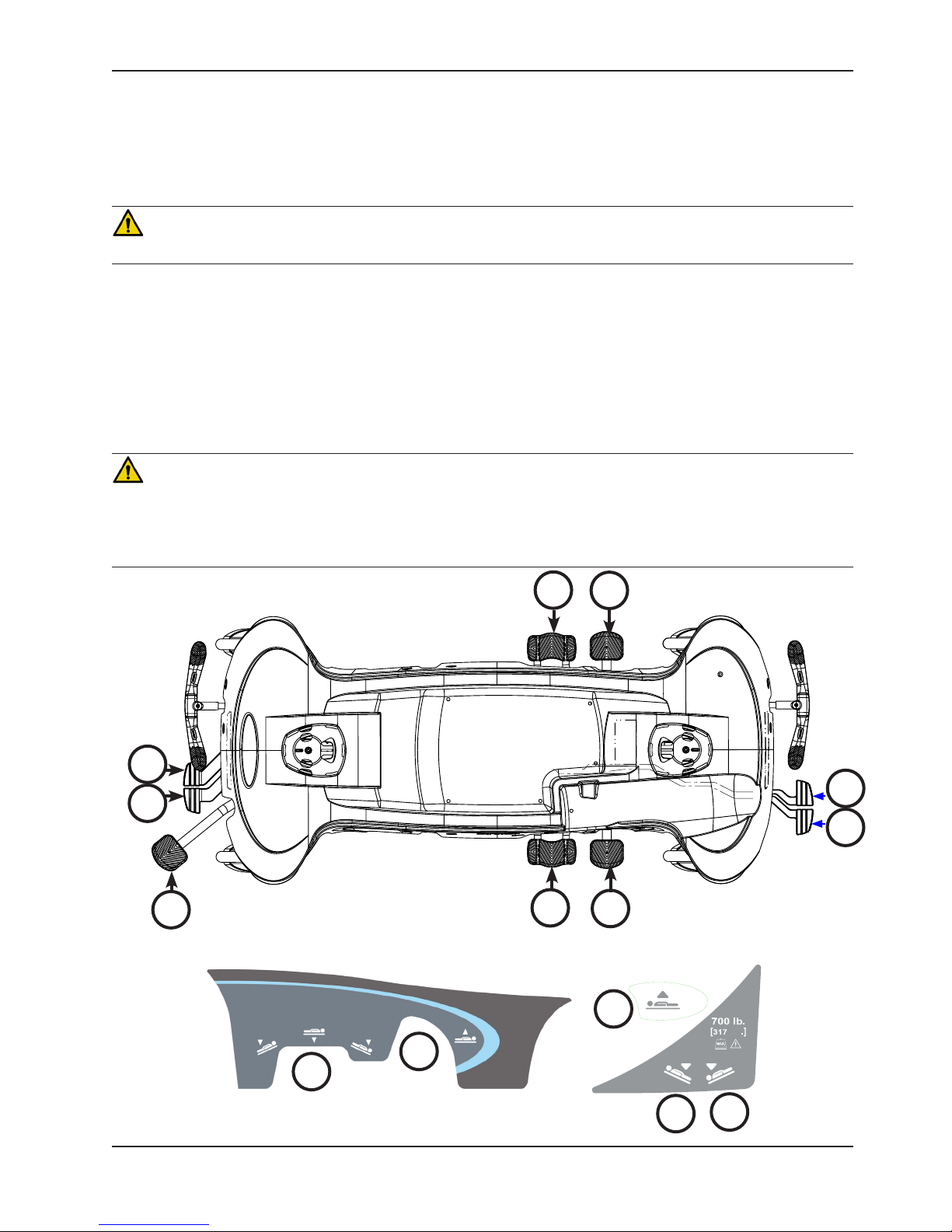
OPERATING THE BASE CONTROLS - SIDE CONTROL HYDRAULICS
To operate the base controls, see Figure 7 to locate which pedals are used for what operation.
CAUTION
To avoid damage, remove any equipment that may be in the way before raising or lowering the litter height.
To raise the litter height, pump pedal (A) repeatedly until the desired height is achieved.
To lower both ends of the litter together, depress the center of pedal (B).
To lower only the head end of the litter, depress the side of pedal (B) closest to the head end of the stretcher.
To lower only the foot end of the litter, depress the side of pedal (B) closest to the foot end of the stretcher.
WARNING
• Patients should be discouraged from sitting directly on the ends of the stretcher. Excessive weight could cause
the litter surface to tip up, possibly causing patient injury.
• Leave the stretcher height in the lowest position when the patient is left unattended. Leaving the stretcher height in
a raised position could increase the chance of patient falls and injury.
B A
B
Figure 7: Stretcher Base Controls - Side Control
A
Head End
Return To Table of Contents
22 1115 -10 9 - 0 01 R EV D www.stryker.com
A
B
Figure 8: Side Base Control Label
Page 23
Operation Guide
OPERATING THE BASE CONTROLS - OPTIONAL THREE-SIDED AND FOUR-SIDED CONTROL
HYDRAULICS
To operate the base controls, see Figure 9 to locate which pedals are used for what operation.
CAUTION
To avoid damage, remove any equipment that may be in the way before raising or lowering the litter height.
To raise the litter height, pump pedal (A) repeatedly until the desired height is achieved.
To lower both ends of the litter together, depress pedal (B) and pedal (D) together using the same foot or depress in
the center of pedal (C).
To lower the foot end of the litter, depress pedal (B) or the side of pedal (C) closest to the foot end.
To lower the head end of the litter, depress pedal (D) or the side of pedal (C) closest to the head end.
WARNING
• Patients should be discouraged from sitting directly on the ends of the stretcher. Excessive weight could cause
the litter surface to tip up, possibly causing patient injury.
• Leave the stretcher height in the lowest position when the patient is left unattended. Leaving the stretcher height in
a raised position could increase the chance of patient falls and injury.
B
D
A
C
C
Figure 9: Stretcher Base Controls - Optional Three-Sided and Four-Sided Control
A
A
A
A
C
C
A
B
D
Head End
kg
Figure 10 : Side Base Three-Sided or Four-Sided Control Label
www.stryker.com 1115 -10 9 - 0 01 R EV D 23
Figure 11:
Label A
B
D
Return To Table of Contents
Page 24

Operation Guide
RAISING AND LOWERING THE LITTER HEIGHT - OPTIONAL ELECTRIC LIFT
Ensure that the power cord is plugged into a properly grounded, hospital grade wall outlet before using the optional
electric lift.
CAUTION
To avoid damage, remove any equipment that may be in the way before raising or lowering the litter height.
To raise the litter height electrically, depress pedal (A) (see Figure 7 on page 22 or Figure 9 on page 23). The
litter will begin to raise. Hold the pedal down until the desired litter height is achieved. Release the pedal at any time
to stop the litter motion.
To lower the litter height manually, see the “Operating the Base Controls - Side Control Hydraulics” information on
page 22 or “Operating the Base Controls - Optional Three-Sided or Four-Sided Hydraulic Controls information” on
page 23. The litter height does not lower electrically.
WARNING
• Patients should be discouraged from sitting directly on the ends of the stretcher. Excessive weight could cause
the litter surface to tip up, possibly causing patient injury.
• Leave the stretcher height in the lowest position when the patient is left unattended. Leaving the stretcher height in
a raised position could increase the chance of patient falls and injury.
Return To Table of Contents
24 1115 -10 9 - 0 01 R EV D www.stryker.com
Page 25

Operation Guide
ADJUSTING TRENDELENBURG/REVERSE TRENDELENBURG POSITIONS - SIDE CONTROL
HYDRAULICS
Litter height must first be raised in order to achieve a Trendelenburg or reverse Trendelenburg position.
CAUTION
• To avoid damage, remove any equipment that may be in the way before raising or lowering the litter height.
• Do not raise the unit (hydraulics on base) with a patient lift under the stretcher.
For Trendelenburg positioning (head down), depress the side of pedal (B) closest to the head end (see Figure 7 on
page 22).
For reverse Trendelenburg positioning (foot down), depress the side of pedal (B) closest to the foot end (see Figure
7 on page 22).
To lower the stretcher from reverse Trendelenburg position, depress pedal (A) once to raise the foot end of the
stretcher, and then depress pedal (B) (see Figure 7 on page 22).
Note: The higher the litter is before pedal (B) is activated, the greater the Trendelenburg or reverse Trendelenburg
angle will be. (Maximum Trendelenburg angle is +17°. Maximum reverse Trendelenburg angle is -17°.)
ADJUSTING TRENDELENBURG/REVERSE TRENDELENBURG POSITIONS - OPTIONAL THREE-SIDED
OR FOUR-SIDED CONTROL HYDRAULICS
Litter height must first be raised in order to achieve a Trendelenburg or reverse Trendelenburg position.
CAUTION
• To avoid damage, remove any equipment that may be in the way before raising or lowering the litter height.
• Do not raise the unit (hydraulics on base) with a patient lift under the stretcher.
For Trendelenburg positioning (head down) (see Figure 8 on page 23):
• Depress pedal (D) at the foot end of the unit or
• Depress the side of pedal (C), located on the patient left or patient right side, closest to the head end of the unit.
For reverse Trendelenburg positioning (foot down) (see Figure 8 on page 23):
• Depress pedal (B) at the foot end of the unit or
• Depress the side of pedal (C), located on the patient left or patient right side, closest to the foot end of the unit.
To lower the stretcher from reverse Trendelenburg position, depress pedal (A) once to raise the foot end of the
stretcher, and then depress pedal (C) or (D) (see Figure 8 on page 23).
Note: The higher the litter is before pedal (B), (C), or (D) is activated, the greater the Trendelenburg or reverse
Trendelenburg angle will be. (Maximum Trendelenburg angle is +17°. Maximum reverse Trendelenburg angle is -17°.)
www.stryker.com 1115 -10 9 - 0 01 R EV D 25
Return To Table of Contents
Page 26
Operation Guide
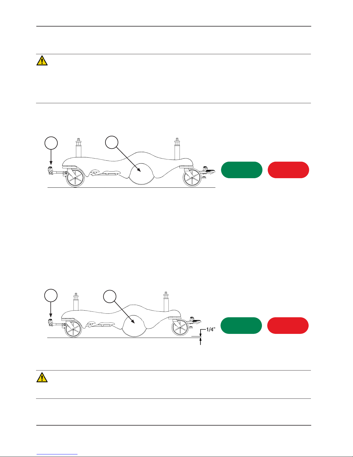
OPERATING THE BIG WHEEL®
WARNING
• Make sure that the brakes are completely released before attempting to move the unit. Attempting to move the unit
with the brakes engaged could result in injury to the user and/or patient.
• If your unit is equipped with the optional electric lift/litter, unplug the power cord from the power outlet before
transporting or cleaning the unit. To unplug, grasp the mold near the outlet and pull the cord in a direction parallel
to the floor (not at an angle).
When the brake/steer pedal (A) is in the neutral or brake position, the Big Wheel (B) is elevated approximately 3/4”
and the stretcher rests on the four casters as shown in Figure 12. See page 21 for pedal operations.
A
B
Steer/Brake Label
Figure 12: Neutral or Brake Position
Note: The two Big Wheels (B) do not pivot. The stretcher cannot be moved directly sideways with the Big Wheel (B)
activated.
With the pedal (A) in the neutral position, the stretcher can be moved in any direction including sideways as shown
in Figure 12. See page 21 for pedal operations.
When the brake/steer pedal (A) is in the steer position, the foot end casters are elevated approximately 1/4” and the
stretcher rests on the two head end casters and the two Big Wheels (B) as shown in Figure 13. This provides increased
mobility and ease of steering the stretcher. See page 21 for pedal operations.
A
B
CAUTION
Do not engage the steer pedal when the Big Wheel is resting on a threshold or other raised area. The force required to
engage the Big Wheel will be higher than normal, possibly causing damage.
Return To Table of Contents
26 1115 -10 9 - 0 01 R EV D www.stryker.com
Steer/Brake Label
Figure 13: Steer Position
Page 27

Operation Guide
OPERATING THE SIDERAILS
Raising and lowering the siderails safely is a two-handed operation. Use one hand to hold and position the siderail and
the other hand to operate the siderail latch.
To raise the siderails, pull up on the siderail (A) and raise it to the highest position until the latch (B) engages as shown
in Figure 14.
WARNING
• After raising the siderails, pull firmly on the siderail to ensure that it is securely locked into the up position. Siderails
are not intended to serve as a patient restraint device to keep patients from exiting the unit. Siderails are intended
to keep a patient from inadvertently rolling off the unit. It is the responsibility of the attending medical personnel
to determine the degree of restraint necessary to ensure that a patient will remain in place. Failure to utilize the
siderails properly could result in patient injury.
• Leave the stretcher height in the lowest position when the patient is left unattended. Leaving the stretcher height
in a raised position could increase the chance of patient falls and injury.
• When using any mattress thicker than 2.5 inches or when using a mattress overlay with the Prime X option, extra
caution and operator supervision is recommended to reduce the risk of patient falls due to lesser siderail coverage.
A
B
Figure 14: Siderails
To lower the siderails, pull up on the latch (B) and guide the siderail to the lowest position as shown in Figure 14. The
latches (B) are colored yellow for easy identification.
WARNING
When lowering the siderail to the collapsed position, keep extremities of patients and staff away from the siderail spindles
or injury could occur.
Note: The foot end of the siderail top rail can be used as a push/pull handle.
CAUTION
To avoid injury or damage to the equipment, do not allow the siderail to lower on its own.
Note: There is a dual siderail latch option available with latches on both ends of the stretcher.
www.stryker.com 1115 -10 9 - 0 01 R EV D 27
Return To Table of Contents
Page 28

Operation Guide
OPERATING THE SIDERAIL PATIENT CONTROLS - OPTIONAL ELECTRIC LITTER (NOT AVAILABLE
WITH PRIME X OPTION)
Ensure that the power cord is plugged into a properly grounded, hospital grade wall outlet before using the optional
electric litter.
Each siderail has backlit controls to allow the patient to position the fowler and gatch as shown in Figure 15. The
power cord must be plugged into the wall socket for the patient controls to operate. When the stretcher is plugged in
(powered) and the controls are unlocked (see page 30), the white buttons are illuminated.
Note: The siderail patient controls are positioned in a staggered location on each side of the stretcher for easy patient
access.
WARNING
Powered stretcher mechanisms can cause serious injury. Operate stretcher only with persons clear of mechanisms.
34
Button Button Name Button Function
1 Gatch Down Press to lower the gatch (foot section)
2 Gatch Up Press to raise the gatch (foot section)
3 Fowler Up Press to raise the fowler (head section)
4 Fowler Down Press to lower the fowler (head section)
Return To Table of Contents
28 1115 -10 9 - 0 01 R EV D www.stryker.com
2 1
Figure 15: Siderail Patient Controls
21
3 4
Patient Right SiderailPatient Left Siderail
Page 29

Operation Guide
OPERATING THE FOOT END NURSING CONTROLS - OPTIONAL ELECTRIC LITTER (NOT AVAILABLE
WITH PRIME X OPTION)
Ensure that the power cord is plugged into a properly grounded, hospital grade wall outlet before using the optional
electric litter.
The foot end nursing controls allow the operator to position the fowler and gatch as shown in Figure 16. The power
cord must be plugged into the wall socket for the nursing controls to operate.
WARNING
Powered stretcher mechanisms can cause serious injury. Operate stretcher only with persons clear of mechanisms.
123 4
Figure 16: Foot End Nursing Controls - Optional Electric Litter
Button Button Name Button Function
1 Gatch Down Press to lower the gatch (foot section)
2 Gatch Up Press to raise the gatch (foot section)
3 Fowler Up Press to raise the fowler (head section)
4 Fowler Down Press to lower the fowler (head section)
www.stryker.com 1115 -10 9 - 0 01 R EV D 29
Return To Table of Contents
Page 30

Operation Guide
USING PATIENT CONTROL LOCKOUT - OPTIONAL ELECTRIC LITTER (NOT AVAILABLE WITH PRIME X
OPTION)
Ensure that the power cord is plugged into a properly
grounded, hospital grade wall outlet before using the
optional electric litter.
A
You can press the patient control lockout button to prevent
the patient from using the siderail patient controls to move
the fowler and gatch. The patient control lockout button is
located at the foot end of the stretcher.
B
To lock the siderail patient controls, press the Lock/
Unlock (A) button as shown in Figure 17. The lock icon (B)
is illuminated amber while the patient controls are locked.
The foot end nursing controls are not locked.
Note: When the siderail patient controls are locked, the
siderail patient controls are not backlit.
To unlock the siderail patient controls, press the Lock/Unlock (A) button as shown in Figure 17. The unlock icon (C)
is illuminated green when the patient controls are unlocked.
Figure 17: Patient Control Lockout
AC
OPERATING THE OPTIONAL PUSH HANDLES
To use the push handles, pivot the handles (A) up and push down until they are locked into position (Figure 18).
To store the push handles, lift the handles (B) up and pivot them down to store in the handle rests (Figure 19).
CAUTION
The push handles were designed for use while transporting the stretcher. Avoid using other parts of the stretcher as
push/pull devices because damage could occur.
A
Figure 18: Push Handles Open
Return To Table of Contents
30 1115 -1 09 - 0 01 REV D www.stryker.com
B
Figure 19: Push Handles Stored
Page 31

Operation Guide
OPERATING THE PNEUMATIC FOWLER - NON-ELECTRIC
To raise the fowler, squeeze either or both of the yellow fowler handles (A) for pneumatic assist until the fowler has
reached the desired angle (between 0 and 90 degrees) as shown in Figures 20 and 21.
To lower the fowler, squeeze either or both of the yellow fowler handles (A) and push down until the fowler has reached
the desired angle (between 90 and 0 degrees) as shown in Figures 20 and 21.
The drop seat/lift assist fowler uses the weight of the patient for additional assistance with raising the fowler. It also
helps keep the patient from sliding toward the foot end of the stretcher when the fowler is raised.
WARNING
• Operation of the fowler is a manual procedure. Use caution when raising the fowler while a patient is on the
stretcher. Use proper lifting techniques and get additional assistance, if necessary. Failure to use proper lifting
techniques could cause injury to the operator.
• Keep hands/fingers clear of the area around the fowler release handle and the fowler frame when lowering the
fowler. Injury could result if care is not taken when lowering the fowler.
A
Figure 20: Pneumatic Fowler - Prime Figure 21: Pneumatic Fowler - Prime X Option
A
www.stryker.com 1115 -10 9 - 0 01 R EV D 31
Return To Table of Contents
Page 32

Operation Guide
OPERATING THE FOWLER - OPTIONAL ELECTRIC LITTER (NOT AVAILABLE WITH PRIME X OPTION)
Ensure that the power cord is plugged into a properly grounded, hospital grade wall outlet before using the optional
electric litter.
To raise the fowler, press the UP (3) button on the patient siderail controls (A) or foot end nursing controls (B) until the
fowler has reached the desired angle (between 0 and 70 degrees) as shown in Figure 22.
To lower the fowler, press the DOWN (4) button until the fowler has reached the desired angle (between 70 and 0
degrees) as shown in Figure 22.
The drop seat/lift assist fowler uses the weight of the patient for additional assistance with raising the fowler. It also
helps keep the patient from sliding toward the foot end of the stretcher when the fowler is raised.
WARNING
• Keep hands/fingers clear of the area around the fowler release handle and the fowler frame when lowering the
fowler. Injury could result if care is not taken when lowering the fowler.
• Powered stretcher mechanisms can cause serious injury. Operate stretcher only with persons clear of mechanisms.
B
A
21
3 4
123 4
Return To Table of Contents
32 1115 -10 9 - 0 01 R EV D www.stryker.com
Figure 22: Fowler - Electric Option
Page 33

Operation Guide
OPERATING THE OPTIONAL GATCH - NON-ELECTRIC (NOT AVAILABLE WITH PRIME X OPTION)
To raise the gatch, pump handle (B) repeatedly to the left until the gatch has reached the desired height (5.5”/14 cm
minimum) as shown in Figure 23.
Note: You cannot raise the gatch manually if your unit is equipped with the optional electric litter.
To lower the gatch, pull handle (A) until the gatch has reached the desired height (5.5”/14 cm minimum) as shown in
Figure 23.
CAUTION
The weight capacity of the gatch
is 200 lb. Do not sit or stand on
the gatch. Injury or damage to the
equipment could occur.
A
A
Figure 23: Gatch - Foot End
To prop the foot end of the gatch up, lift up on the end of the gatch, allowing the prop rod to swing down and engage
in the bracket as shown in Figure 25.
To release the prop, lift up on the end of the gatch, swing the prop rod toward the head end of the unit to disengage
the bracket and lower the foot end as shown in Figure 25.
B
Figure 24: Gatch Label
WARNING
To avoid the risk of injury, ensure
that the gatch prop rod is fully
raised and securely placed into
position (Figure 25).
Figure 25: Gatch
www.stryker.com 1115 -10 9 - 0 01 R EV D 33
Return To Table of Contents
Page 34

Operation Guide
OPERATING THE GATCH - OPTIONAL ELECTRIC LITTER (NOT AVAILABLE WITH PRIME X OPTION)
Ensure that the power cord is plugged into a properly grounded, hospital grade wall outlet before using the optional
electric litter.
To raise the gatch, press the UP (2) button on the siderail patient controls (A) or foot end nursing controls (B) until the
gatch has reached the desired height (5.5”/14 cm minimum) as shown in Figure 26.
To lower the gatch, press the DOWN (1) button until the gatch has reached the desired height (5.5”/14 cm minimum)
as shown in Figure 26.
WARNING
Use caution when operating the gatch while a patient is on the stretcher. Powered stretcher mechanisms can cause
serious injury. Operate stretcher only with persons clear of mechanisms.
A
B
123 4
Figure 26: Gatch - Electric Option
21
3 4
CAUTION
The weight capacity of the gatch is 200 lb. Do not sit or stand on the gatch. Injury or damage to the equipment could
occur.
Return To Table of Contents
34 1115 -10 9 - 0 01 R EV D www.stryker.com
Page 35

Operation Guide
OPERATING THE RECOVERY CHAIR (NOT AVAILABLE WITH PRIME X OPTION)
CAUTION
To achieve recovery chair position, your stretcher must be equipped with the lift assist backrest and gatch options.
To place the stretcher into the recovery chair position as shown in Figure 27:
1. Raise the fowler to a seated position (for manual operation, see page 31; for the optional electric litter operation,
see page 32).
2. Fully raise the gatch (for manual operation, see page 33; for the optional electric litter operation, see page
34).
3. Raise the stretcher to its highest height (for side control, see page 22; for three-sided or four-sided controls, see
page 23; for optional electric litter operation, see page 24).
4. Place the stretcher into the full reverse Trendelenburg position (see page 25).
Figure 27: Recovery Chair
To lower the stretcher from the recovery chair position:
1. Raise the stretcher to its highest height (for side control, see page 22; for three-sided or four-sided controls, see
page 23; for optional electric litter operation, see page 24).
2. Lower the fowler from the seated position (for manual operation, see page 31; for the optional electric litter
operation, see page 32).
3. Lower the gatch (for manual operation, see page 33; for the optional electric litter operation, see page 34).
WARNING
Use caution when operating the recovery chair while a patient is on the stretcher. Powered stretcher mechanisms can
cause serious injury. Operate stretcher only with persons clear of mechanisms.
Return To Table of Contents
www.stryker.com 1115 -10 9 - 0 01 R EV D 35
Page 36

Operation Guide
USING THE BASE HOOD FOR STORAGE
You can store items in the base hood (A) as shown in Figure 28.
CAUTION
• The weight capacity of the base hood is 60 lb. Do not sit or stand on the base hood. Injury or damage to the
equipment could occur.
• Do not step on the base hood.
• Do not use the cutout for the oxygen bottle holder on the base hood for the storage of oxygen bottles or patient
belongings.
Note: Clean the base hood storage area regularly.
A
Figure 28: Base Hood Storage
Return To Table of Contents
36 1115 -1 0 9 - 0 01 R EV D www.stryker.com
Page 37

Operation Guide
USING THE OPTIONAL PUMP RACK
WARNING
• To avoid patient injury or equipment damage, all lines from any equipment stored on the pump rack must be
diverted away from the gatch handles.
• To avoid patient injury or equipment damage, do not lift the stretcher by the pump rack.
• To avoid equipment damage, remove any equipment from the pump rack that may be in the way before lowering
the litter.
• To avoid equipment damage while transporting the stretcher, verify that any equipment on the pump rack can safely
pass through door openings and under light fixtures.
CAUTION
• The weight capacity of the pump rack is 40 lb.
• Do not use the pump rack as a push/pull device, because equipment damage could occur.
Note: The pump rack is an option that may have been installed at the foot end of the stretcher. The choice was made
at the time that the stretcher was purchased.
The pump rack (A) can be used for the storage and transportation of stretcher equipment (Figure 29).
A
www.stryker.com 1115 -10 9 - 0 01 R EV D 37
Figure 29: Pump Rack
Return To Table of Contents
Page 38

Operation Guide
USING THE OPTIONAL RETRACTABLE CORD REEL - ELECTRIC LIFT/LITTER OPTION
The retractable cord reel (A) stores the stretcher power cord during transport as shown in Figure 30.
To use the retractable cord reel:
1. Pull the cord out of the reel to the desired length.
2. Plug the power cord into a properly grounded, hospital
grade wall outlet.
To store the power cord:
1. Unplug the plug by grasping the mold near the outlet and
pull the cord in a direction parallel to the floor (not at an
angle).
2. Tug and release the cord to retract the cord back into the
cord reel.
WARNING
If your unit is equipped with the optional electric lift/litter, unplug
the power cord from the power outlet before transporting or
cleaning the unit. To unplug, grasp the mold near the outlet and
pull the cord in a direction parallel to the floor (not at an angle).
A
Figure 30: Optional Retractable Cord Reel
Return To Table of Contents
38 1115 -1 09 - 0 01 REV D www.stryker.com
Page 39

Operation Guide
OPERATING THE OPTIONAL SCALE SYSTEM
The scale option (see page 40) is available for units without the optional electric litter.
The scale option (see page 42) is available for units with the optional electric litter. The scale system has a battery
backup option, so the standby icon indicates when the unit is unplugged and operating with battery backup.
The chaperone option (see page 44) is available for units with the optional electric litter scale option. The scale
system with chaperone (stretcher exit) has a battery backup option, so the standby icon indicates when the unit is
unplugged and operating with battery backup. The chaperone option also allows you to set zone controls to alert an
operator when a patient may be attempting to exit the stretcher.
www.stryker.com 1115 -10 9 - 0 01 R EV D 39
Return To Table of Contents
Page 40

Operation Guide
OPERATING THE OPTIONAL SCALE SYSTEM - NON-ELECTRIC LITTER
1
42 3
Figure 31: Scale System-Non-Electric Litter
Ref Icon/Button Description Action Display
1 Displays patient weight, unit of measurement and
battery status.
2 Push to toggle between patient weight in pounds
or weight in kilograms.
3 Push to weigh the patient. The display shows the
patient’s weight for approximately 40 seconds
before turning off.
4 Push and hold for 2 seconds to zero the scale
system before putting a patient on the stretcher.
If the display flashes “hold”, press and hold
the Zero button again until the display reads
“rel” (release). Release the Zero button. The
display flashes “000.0”, then displays “000.0”.
The system is not zeroed until the “000.0” stops
flashing. For the most accurate results, always
zero the scale system before putting a new
patient on the stretcher. The display shuts off
after approximately 40 seconds.
Note: Do not touch the stretcher while the scale system is weighing or zeroing. The patient must remain still while
the system is weighing. If the patient is moving, the system will try for 20 seconds to get a stable weight or zero value
before displaying the error message .
To convert the weight of
the patient to kilograms,
press and release lb/kg.
Repeat to return
to pounds.
Press and release
Weigh
Press and hold Zero
Release Zero
XXX.X kg
XXX.X lb
_ _ _ _
XXX.X lb
hold
rel
000.0 (flashing)
000.0 (solid)
If there is a loose connection or a malfunctioning component, the display will show “Err”. Attempt the function again.
If the system is functional, “Good” will display and the scale system is ready to use. If the malfunction is still present,
the display shows “Err” again. Call Stryker technical support at 800-327-0770.
To meet the accuracy claim as stated in the product specification on page 11, the patient surface must be in the flat
position (fowler and gatch down) and the stretcher cannot exceed 5 degrees of Trendelenburg/reverse Trendelenburg.
Return To Table of Contents
40 1115 -109 -001 RE V D www.stryker.com
Page 41

Operation Guide
REPLACING THE OPTIONAL SCALE SYSTEM BATTERIES - NON-ELECTRIC LITTER
To avoid completely draining the batteries and having the optional scale system shut down, replace the batteries
whenever only one of the charge indicator bars on the display (1) is black as shown on page 40.
To replace the scale system batteries:
1. Remove the Phillips head screws that hold the battery compartment cover to the display assembly.
2. Replace all four AA batteries.
• Install the positive and negative poles as indicated on the battery holder.
• Use only Alkaline type (LR6) batteries.
• Do not mix old and new batteries.
• Properly dispose of the old batteries in accordance with local regulations.
3. Reinstall the screws and the cover.
If the display is flashing “Lo batt”, then the batteries are drained and the scale system is disabled. Replace the batteries
with four new AA batteries as described above.
www.stryker.com 1115 -10 9 - 0 01 R EV D 41
Return To Table of Contents
Page 42

Operation Guide
OPERATING THE OPTIONAL SCALE SYSTEM - ELECTRIC LITTER OPTION WITHOUT CHAPERONE
(NOT AVAILABLE WITH PRIME X OPTION)
1
4
Figure 32: Scale System-Electric Litter Without Chaperone
Ref Icon/Button Description Action Display
1 Displays patient weight, unit of measurement and
battery status.
2 Push to toggle between patient weight in pounds
or weight in kilograms.
3 Push and hold for 2 seconds to zero the scale
system before putting a patient on the stretcher.
If the display flashes “hold”, press and hold
the Zero button again until the display reads
“rel” (release). Release the Zero button. The
display flashes “000.0”, then displays “000.0”.
The system is not zeroed until the “000.0” stops
flashing. For the most accurate results, always
zero the scale system before putting a new
patient on the stretcher. The display shuts off
after approximately 40 seconds.
4 When the scale system is unplugged and
operating with battery backup, the standby
indicator is amber. When the unit is plugged in,
the standby indicator is green.
5 Push to weigh the patient. The display shows the
patient’s weight for approximately 40 seconds
before turning off.
52 3
To convert the weight of
the patient to kilograms,
press and release lb/kg.
Repeat to return
to pounds.
Press and hold Zero
Release Zero
Press and release
Weigh
XXX.X kg
XXX.X lb
hold
rel
000.0 (flashing)
000.0 (solid)
_ _ _ _
XXX.X lb
Note: Do not touch the stretcher while the scale system is weighing or zeroing. The patient must remain still while
the system is weighing. If the patient is moving, the system will try for 20 seconds to get a stable weight or zero value
before displaying the error message .
If there is a loose connection or a malfunctioning component, the display will show “Err”. Attempt the function again. If
the malfunction is still present, the display shows “Err” again. Call Stryker technical support at 800-327-0770.
To meet the accuracy claim as stated in the product specification on page 11, the patient surface must be in the flat
position (fowler and gatch down) and the stretcher cannot exceed 5 degrees of Trendelenburg/reverse Trendelenburg.
Return To Table of Contents
42 1115 -10 9 - 0 01 R EV D www.stryker.com
Page 43

Operation Guide
CHARGING THE OPTIONAL SCALE SYSTEM BATTERY PACK - ELECTRIC LITTER OPTION (NOT
AVAILABLE WITH PRIME X OPTION)
To avoid completely draining the battery pack and having the optional scale system shut down, charge the battery pack
whenever only one of the charge indicator bars on the display (1) is black as shown on page 42.
The battery pack charges whenever the power cord is plugged into a properly grounded, hospital grade power source.
When the unit is stationary, you should plug the power cord into a power source whenever possible.
The optional scale system - electric litter option requires one 10.8V Li-Ion battery pack (0058-134-000). When fully
discharged, the battery pack requires approximately 3 hours of charging time to recharge.
www.stryker.com 1115 -10 9 - 0 01 R EV D 43
Return To Table of Contents
Page 44

Operation Guide
OPERATING THE OPTIONAL SCALE SYSTEM - ELECTRIC LITTER OPTION WITH CHAPERONE (NOT
AVAILABLE WITH PRIME X OPTION)
2 31
4
5 6 7
8
Figure 33: Scale Sysem-Electric Litter With Chaperone
Ref Icon/Button Description Action Display
1 Indicates when Zone 1 is armed. Allows the patient to move around
the stretcher freely, but cannot begin to exit the stretcher or the
alert with sound.
2 Displays patient weight, unit of measurement and battery status
3 Push to toggle between patient weight in pounds or weight in
kilograms
4 Indicates when Zone 2 is armed. Zone 2 is more restrictive than
Zone 1. When this zone is selected, the stretcher measures the
patient’s center of gravity. If the patient’s center of gravity moves
outside the preset boundary, an alert will sound.
5 Push once to arm Zone 1. Push twice to arm Zone 2. Once armed
or when alerting, press once to disarm.
To convert the weight of
the patient to kilograms,
press and release lb/kg.
Repeat to return to pounds.
Press and release Arm/Disarm On 1
XXX.X kg
XXX.X lb
On 2
Off
6 When the scale system is unplugged and operating with battery
backup, the standby indicator is amber. When the unit is plugged in,
the standby indicator is green.
7 Push to weigh the patient. The display shows the patient’s weight for
approximately 40 seconds before turning off.
8 Push and hold for 2 seconds to zero the scale system before putting
a patient on the stretcher. If the display flashes “hold”, press and
hold the Zero button again until the display reads “rel” (release).
Release the Zero button. The display flashes “000.0”, then displays
“000.0”. The system is not zeroed until the “000.0” stops flashing.
For the most accurate results, always zero the scale system before
putting a new patient on the stretcher. The display shuts off after
approximately 40 seconds.
Return To Table of Contents
44 1115 -1 09 - 0 01 REV D www.stryker.com
Press and release Weigh _ _ _ _
XXX.X lb
Press and hold Zero
Release Zero
hold
rel
000.0
(flashing)
000.0 (solid)
Page 45

Operation Guide
OPERATING THE OPTIONAL SCALE SYSTEM - ELECTRIC LITTER OPTION WITH CHAPERONE (NOT
AVAILABLE WITH PRIME X OPTION) (CONTINUED)
Note: Do not touch the stretcher while the scale system is weighing or zeroing. The patient must remain still while
the system is weighing. If the patient is moving, the system will try for 20 seconds to get a stable weight or zero value
before displaying the error message .
If there is a loose connection or a malfunctioning component, the display will show “Err”. Attempt the function again. If
the malfunction is still present, the display shows “Err” again. Call Stryker technical support at 800-327-0770.
To meet the accuracy claim as stated in the product specification on page 11, the patient surface must be in the flat
position (fowler and gatch down) and the stretcher cannot exceed 5 degrees of Trendelenburg/reverse Trendelenburg.
OPERATING THE CHAPERONE (STRETCHER EXIT) OPTION (NOT AVAILABLE WITH PRIME X OPTION)
To use the chaperone with zone control option:
1. Press the Zero button to reset the scale system.
Note: Before positioning the patient on the stretcher, the scale system must be zeroed for the chaperone function
to operate properly.
2. Position the patient on the stretcher and press the Arm/Disarm button to activate the chaperone function. The
“Zone 1” LED will turn on. The chaperone function with zone control automatically selects Zone 1.
3. To select Zone 2 instead, press the Arm/Disarm button twice within three seconds of each other. The “Zone 2”
LED will turn on.
To deactivate the chaperone function, press the Arm/Disarm button. The selected Zone light will turn off.
CHARGING THE OPTIONAL SCALE SYSTEM BATTERY PACK - ELECTRIC LITTER OPTION WITH
CHAPERONE (NOT AVAILABLE WITH PRIME X OPTION)
To avoid completely draining the battery pack and having the optional scale system shut down, charge the battery pack
whenever only one of the charge indicator bars on the display (2) is black as shown on page 44.
The battery pack charges whenever the power cord is plugged into a properly grounded, hospital grade power source.
When the unit is stationary, you should plug the power cord into a power source whenever possible.
The optional scale system - with chaperone option only requires one 10.8V Li-Ion battery pack (0058-134-000). When
fully discharged, the battery pack requires approximately 3 hours of charging time to recharge.
www.stryker.com 1115 -10 9 - 0 01 R EV D 45
Return To Table of Contents
Page 46

Operation Guide
OPERATING THE CHAPERONE (STRETCHER EXIT) OPTION - OPTIONAL SETUP (NOT AVAILABLE
WITH PRIME X OPTION)
You can change the pattern and volume of the alert.
5
1 2
Figure 34: Chaperone Panel
To change the alert pattern:
1. Press and hold the Arm/Disarm (1) button and the Weigh (2) button together for 6 seconds. Ignore all display
messages until “Ptrn” appears on the display (5).
2. Release both buttons. The display (5) shows the current setting “P (1-10)”.
3. Press the Arm/Disarm (1) or Weigh (2) button to change the setting. As you press each button to select your
setting, a brief sample is played.
4. Press and hold the Arm/Disarm (1) button and the Weigh (2) button together for 6 seconds until “Set” appears on
the display (5) to save your selected setting.
5. Release both buttons. The display (5) shows “P (1-10)”. A brief sample of your selected pattern will confirm your
sound setting.
4
3
To change the alert volume:
1. Press and hold the Zero (3) button and the lb/kg (4) button together for 6 seconds. Ignore all display messages
until “UOL” appears on the display (5).
2. Release both buttons. The display (5) shows the current setting “L (1-4)”.
3. Press the Zero (3) button or lb/kg (4) button to change the setting. As you press each button to select your setting,
a brief sample is played.
4. Press and hold the Zero (3) button and the lb/kg (4) button together for 6 seconds until “Set” appears on the
display (5) to save your selected setting.
5. Release both buttons. The display (5) shows “L (1-4)”. A brief sample of your selected volume will confirm your
sound setting.
Return To Table of Contents
46 1115 -1 09- 0 01 REV D www.stryker.com
Page 47

Operation Guide
USING X-RAY CASSETTES - PRIME X OPTION
The Prime X option provides an articulating radiographic patient support surface and a platform below the patient
support surface for X-Ray cassette placement to allow the capture of clinical X-Rays (AP Full Body, optional Full Body
Lateral, and optional Upright Chest) when used in conjunction with medical X-Ray systems.
WARNING
When using the Prime X option in conjunction with devices that generate X-radiation, the generating devices may
produce residual, stray, and/or scattered radiation. Users should refer to local, state, and federal use guidelines as
well as appropriate facility protocols for safety before use. Special attention should be given when performing X-Rays
with the stretcher’s fowler in the upright position and also when performing X-Rays using a lateral cassette.
You can insert and remove cassettes from the head end,
foot end and both sides of the stretcher as shown in
Figure 35.
Center the patient on the stretcher by using the position
indicator labels that are located on all sides of the stretcher.
WARNING
The Prime X option is not recommended for use with a
Stryker Pioneer mattress or a mattress with a thickness
greater than four inches and is not compatible for use with
a C-Arm.
Figure 35: Cassette Locations
www.stryker.com 1115 -10 9 - 0 01 R EV D 47
Return To Table of Contents
Page 48

Operation Guide
USING THE DEFIBRILLATOR TRAY
To install the defibrillator tray, insert the pins on the
defibrillator tray into the footboard sockets at the foot end
of the stretcher as shown in Figure 36. Use the strap to
secure the equipment to the tray.
CAUTION
• To avoid damage, do not put items weighing more
than 30 lb on the defibrillator tray.
• To avoid risk of patient or operator injury, ensure that
all devices placed on the defibrillator tray are securely
strapped to the tray.
• Do not use the defibrillator tray as a push/pull device
because equipment damage could occur.
USING THE FOOT EXTENSION/DEFIBRILLATOR
TRAY
To use as a defibrillator tray, pull out the top knob (A) and
pivot the tray (B) over the foot extension (C) until the tray
extends flat over the foot end of the stretcher as
shown in Figure 37.
To use as a foot extension, pull out knob (A)
and pivot the defibrillator tray back until it locks
against the foot extension (C). While holding onto
the assembly, pull out the bottom knob (D) and
lower the foot extension down until it is flat as
shown in Figure 37.
CAUTION
• If the stretcher is equipped with the optional
foot end I.V. pole, the I.V. pole must be in
the raised position when the foot extension/
defibrillator tray is installed. If the I.V. pole is
not raised, the foot extension will not function
properly and injury could occur.
• To avoid damage, do not put items weighing
more than 30 lb on the foot extender/
defibrillator tray.
• To avoid risk of patient or operator injury, ensure that all devices placed on the defibrillator tray are securely strapped to the tray.
• Do not use the foot extension/defibrillator tray
as a push/pull device because equipment
damage could occur.
D
A
Figure 36: Defibrillator Tray
B
C
Return To Table of Contents
48 1115 -109 -00 1 RE V D www.stryker.com
Figure 37: Foot Extension/
Defibrillator Tray - Foot End
Page 49

Operation Guide
USING THE FOOTBOARD/CHARTHOLDER
To use the footboard/chartholder, insert the footboard/
chartholder supports (A) into the corresponding holes
located at the foot end of the stretcher.
CAUTION
Do not use the footboard/chartholder as a push/pull device
because equipment damage could occur.
USING THE I.V. CADDY
To use the I.V. caddy:
1. Lift the I.V. caddy out of the storage tray or from the
storage clip. Pivot the I.V. caddy to the desired position.
2. Turn knob (A) counterclockwise to loosen the pole
clamp (C).
3. Pivot the knob (A) away from the clamp (B). The clamp
(C) may then be opened.
4. Place the I.V. pole into the clamp (B). Close the clamp
(C) around the I.V. pole and pivot the knob (A) back
into position.
5. Turn the knob (A) clockwise to tighten it. The I.V. pole
is ready to be transported with the unit.
A
Figure 38: Footboard/Chartholder
C
B
A
To remove the I.V. pole from the I.V. caddy:
1. Turn knob (A) counterclockwise to loosen the pole
clamp.
2. Pivot the knob away from the clamp (B), open the
clamp and remove the I.V. pole from the I.V. caddy.
Figure 39: I.V. Caddy
CAUTION
Always store the I.V. caddy when not in use to avoid damaging it when the unit is moved.
WARNING
To avoid the risk of injury to the patient or user or damage to the I.V. pole while transporting the stretcher, make sure that
the I.V. caddy is securely tightened on the I.V. pole.
Return To Table of Contents
www.stryker.com 1115 -10 9 - 0 01 R EV D 49
Page 50

Operation Guide
OPERATING THE FOOT SUPPORTS (NOT AVAILABLE WITH PRIME X OPTION)
WARNING
To avoid the risk of patient injury or equipment damage, do not sit on the foot support.
To use the foot supports (see Figure 40):
1. Loosen the knee knob (A) at the top of the foot support to adjust the side-to-side angle of the foot support (C).
2. Secure the knee knob (A) to lock the foot support in the desired position.
3. Loosen the leg knob (B) on the side of the foot support to adjust the length.
4. Secure the leg knob (B) to lock the foot support in the desired position.
5. Flip the foot support (C) up before positioning patient.
The following options can be purchased, but cannot be utilized while the foot supports are in use:
• Pneumatic Backrest/Stationary Foot Composite
• Lift Assist™ Backrest/Stationary Foot Composite
• Pneumatic Backrest/Hydraulic Knee Gatch
To store the foot supports (see Figure 41):
1. Fully retract the foot supports using leg knob (B).
2. Fold the foot support pads (C) down toward the support bar.
3. Loosen the knee knob (A), rotate the foot supports to the position shown in the Figure 41 below.
4. Tighten to secure in place using the knee knob (A).
C
Figure 40: Foot Support Components Figure 41: Foot Supports In Stored Position
Return To Table of Contents
50 1115 -1 0 9 - 0 01 R EV D www.stryker.com
B
A
A
C
B
Page 51

Operation Guide
OPERATING THE FOOT SUPPORTS (NOT AVAILABLE WITH PRIME X OPTION) (CONTINUED)
CAUTION
• To avoid the risk of equipment damage, do not use the foot support to store patient belongings or other items.
• To avoid injury to the operator, ensure that the operator’s fingers are clear of the mechanism when positioning the
foot support.
• Foot supports should be in the stored position when moving. The stretcher should be in brake position when foot
supports are in use.
• To avoid the risk of damage to the equipment, do not use the foot support as a push/pull device.
• To avoid injury to the patient or operator, ensure foot supports are tightened securely prior to use.
• If the stretcher is equipped with the scale system option, the scale should not be utilized while the foot supports
are in use because inaccurate readings may occur.
• If the stretcher is equipped with the chaperone option, the chaperone option should not be utilized while the foot
supports are in use because false readings may occur.
The following options cannot be purchased if the foot support option is selected:
• Foot End Pop-Up Steering Handles
• Defibrillator Tray
• Defibrillator Tray/Foot Extender/Chart Service
• Serving Tray Holder/Footboard
• Footboard/Chart Holder
• Foot End I.V. Poles
www.stryker.com 1115 -10 9 - 0 01 R EV D 51
Return To Table of Contents
Page 52

Operation Guide
OPERATING THE TWO-STAGE PERMANENTLY ATTACHED I.V. POLE
Note: The two-stage permanently attached I.V. pole is an option and may have been installed at either the head, foot
or both ends of the stretcher. The choice was made at the time that the stretcher was purchased.
To use the two-stage permanently attached I.V. pole:
1. Lift and pivot the pole from the storage position and push down until it is locked into the receptacle.
2. To raise the height of the pole, pull up on the telescoping portion (A) until it locks into place at its fully raised
position.
3. Rotate the I.V. hangers (B) to desired position and hang the I.V. bags.
4. To lower the I.V. pole, turn the latch (C) until section (A) lowers.
A
B
A
C
C
Figure 43: I.V. Pole Latch Detail
Figure 42: I.V. Pole
CAUTION
• To avoid damage, the safe working load of the two-stage permanently attached I.V. pole is 40 lb.
• To avoid damage while transporting the stretcher, verify that the I.V. pole is at a low enough height to allow it to
safely pass through door openings and under light fixtures.
• Do not use the I.V. pole as a push/pull device because equipment damage could occur.
Return To Table of Contents
52 1115 -10 9 - 0 01 R E V D www.stryker.com
Page 53

Operation Guide
OPERATING THE THREE-STAGE PERMANENTLY ATTACHED I.V. POLE
Note: The three-stage permanently attached I.V. pole is an option and may have been installed at either the head, foot
or both ends of the stretcher. The choice was made at the time that the stretcher was purchased.
To use the three-stage permanently attached I.V. pole:
1. Lift and pivot the pole from the storage position and push down until it is locked into the receptacle.
2. To raise the height of the pole, pull up on the telescoping portion (A) until it locks into place at its fully raised
position.
3. For a higher I.V. pole, pull up on section (B). Release section (B) at any desired height and it will lock into place.
4. Rotate the I.V. hangers (C) to the desired position and hang the I.V. bags.
5. To lower the I.V. pole, push up on the red portion of grip (D) while holding onto section (B) until it lowers. Turn latch
(E) until section (A) lowers.
B
A
E
D
C
A
C
E
B
Figure 45: I.V. Pole Latch Detail
D
Figure 44: I.V. Pole
CAUTION
• To avoid damage, the weight of the I.V. bags should not exceed 12 lb while the weight of any one item attached to
each stage of the three-stage permanently attached I.V. pole should not exceed 9.3 lb.
• To avoid damage while transporting the stretcher, verify that the I.V. pole is at a low enough height to allow it to
safely pass through door openings and under light fixtures.
• Do not use the I.V. pole as a push/pull device because equipment damage could occur.
www.stryker.com 1115 -10 9 - 0 01 R EV D 53
Figure 46: I.V. Pole Grip Detail
Return To Table of Contents
Page 54

Operation Guide
OPERATING THE REMOVABLE I.V. POLE
To use the removable I.V. pole:
1. Remove the I.V. pole from the storage trough under the litter and insert into
the receptacle on the corner of the litter frame.
2. To raise the height of the pole, turn the knob (B) counterclockwise and pull
up on the telescoping portion (A) of the pole to raise it to the desired height.
3. Turn the knob (B) clockwise to lock the telescoping portion in place.
CAUTION
• To avoid damage to the removable I.V. pole, the weight of the I.V. bags should
not exceed 40 lb.
• To avoid damage while transporting the stretcher, verify that the I.V. pole is
at a low enough height to allow it to safely pass through door openings and
under light fixtures.
• Do not use the I.V. pole as a push/pull device because equipment damage
could occur.
A
INSTALLING THE SIDERAIL PADS
To install and use the siderail pads, tuck the siderail pad between the mattress
and siderail. Then, attach the Velcro® straps around the top of the siderail to
secure the pad to the siderail.
B
Figure 47: Removable I.V. Pole
Return To Table of Contents
54 1115 -10 9 - 0 01 R EV D www.stryker.com
Page 55

Operation Guide
USING THE UPRIGHT OXYGEN BOTTLE HOLDER
To install the upright oxygen bottle holder, insert the
support bar (A) into the I.V. socket at any of the four litter
corners. Insert the cotter pin (B) through the hole in the
support bar to hold the bottle holder in place as shown in
Figure 48.
CAUTION
• To avoid damage, do not put items weighing more than
40 lb in the upright oxygen bottle holder.
• Do not use the upright oxygen bottle holder as a push/
pull device because equipment damage could occur.
USING THE SERVING TRAY
To use the serving tray, pull out on either end of the
serving tray to extend it to the proper width to fit on top of
the stretcher siderails as shown in Figure 49.
To store the serving tray in the optional serving tray
holder/footboard, push in both ends of the serving tray and
slide it into holder as shown in Figure 50.
CAUTION
• To avoid damage, do not put items weighing more than 30
lb on the serving tray.
• Do not use the serving tray holder/footboard as a push/pull
device because equipment damage could occur.
A
B
Figure 48: Upright Oxygen Bottle Holder
Figure 49: Serving Tray
www.stryker.com 1115 -10 9 - 0 01 R EV D 55
Figure 50: Serving Tray - Foot End
Return To Table of Contents
Page 56

Operation Guide
USING THE RESTRAINT STRAPS
This unit allows the use of ankle, chest, wrist, and body restraints. See Figures 51 and 52 for restraint strap attachment
points. Do not attach restraints straps to the siderail. Stryker makes no recommendation for the use of restraints.
WARNING
• Physical restraints, even if properly secured, may result in serious harm to patients and caregivers. The use of
restraint straps may potentially cause entanglement, entrapment, physical injury, and/or death. Caution must be
used in affixing restraint straps to avoid potential injury to both patients and caregivers.
• Restraint straps and/or devices must be attached only at the identified attachment points of the unit. Failure to do
so may result in patient or caregiver injury. Do not attach restraints straps to the siderail.
• This unit accommodates the use of ankle, chest, wrist, and body restraints. The use of restraint straps is regulated
by state and federal restrictions. Users, caregivers, and/or practitioners should refer to the applicable state and
federal restrictions and the appropriate facility protocols before using any restraint strap and/or device.
Figure 51: Restraint Strap Locations - Prime Figure 52: Restraint Strap Locations - Prime X Option
Return To Table of Contents
56 1115 -10 9 - 0 01 R EV D www.stryker.com
Page 57

Operation Guide
USING THE UPRIGHT X-RAY CASSETTE HOLDER
This unit stores the cassette against the backrest when raised in the upright position to help deliver superior image
quality for chest X-Rays.
WARNING
This device does not offer any protection against X-Ray radiation.
CAUTION
To avoid risk of user injury or damage to the equipment, ensure that the Upright X-Ray Cassette Holder is installed
correctly, following the instructions below.
To use the Upright X-Ray Cassette Holder
1. Raise the fowler section of the stretcher.
2. Position the upright cassette holder, placing the lower retainer guides (A) under the fowler weldment bar (Figure
54).
3. Raise the upright cassette holder until the hooks latch under the fowler weldment frame. Ensure that the upright
cassette holder is securely latched.
4. Insert and remove cassettes from the upright cassette holder from either side of the cassette holder or pull up on
the yellow arrow to release the wire latch (B) on the upright cassette holder, releasing the upright cassette holder
from the fowler weldment, and then position the cassette in the holder.
5. Loosen the knob (E) on the back side of the upright cassette holder and adjust the cassette support rail (D) to
position the cassette in the desired location (Figure 53). Tighten the knob to secure the cassette support rail in
place.
To remove the Upright X-Ray Cassette Holder
1. With the fowler raised, pull up on the yellow arrow (B) to release the wire latch (C) on the upright cassette holder
from the fowler weldment bar (Figures 53 and 54).
2. Lift up on the upright cassette holder to release the lower retainer guides (A) on the upright cassette holder from
the fowler weldment bar (Figure 54).
B
C
A
E
D
Figure 53: Upright X-Ray Cassette Holder
Outside View
www.stryker.com 1115 -10 9 - 0 01 R EV D 57
Figure 54: Upright X-Ray Cassette Holder
Inside View
Return To Table of Contents
Page 58

Operation Guide
USING THE LATERAL CASSETTE HOLDER
This removable cassette holder allows radiologists to take full length C-Spine images, holding virtually any size cassette.
WARNING
This device does not offer any protection against X-Ray radiation.
CAUTION
To avoid risk of user injury or damage to the equipment, ensure that the Lateral X-Ray Cassette Holder is installed
correctly, following the instructions below.
To use the Lateral Cassette Holder
1. Press down on the yellow release button (A) to open the lateral cassette holder (Figure 55).
2. Slide the flat base (B) between the mattress and the patient platform (Figures 55 and 56).
3. Position the lateral cassette holder in the desired location.
4. Place the X-Ray cassette in the cassette canal (C) (Figures 55 and 56).
5. Pull up on the cassette hook (D) to adjust the height of the arm to fit snugly over the X-Ray cassette to hold the
cassette in place (Figure 56).
6. Pull up on the cassette hook (D) to remove the X-Ray cassette from the lateral cassette holder (Figure 56).
7. Remove the lateral cassette holder from between the mattress and patient platform.
8. Press down on the release button to close the lateral cassette holder.
9. Store the lateral cassette holder as appropriate.
A
D
B
B
C
C
Figure 55: Lateral
Cassette Holder
Return To Table of Contents
58 1115 -1 09 - 0 01 R EV D www.stryker.com
Figure 56: Lateral Cassette Holder
Page 59

Cleaning
STRETCHER CLEANING
WARNING
• If your unit is equipped with the optional electric lift/litter, unplug the power cord from the power outlet before
transporting or cleaning the unit. To unplug, grasp the mold near the outlet and pull the cord in a direction parallel
to the floor (not at an angle).
• Do not steam clean the unit.
These instructions are intended to provide recommended cleaning methods for Model 1115 Prime Series Stretchers.
These units are designed to be power-washable. The unit may show some signs of oxidation or discoloration from
continuous washing. However, no degradation of the stretcher’s performance characteristics or functionality will occur
due to power washing as long as the proper procedures are followed.
RECOMMENDED CLEANING METHOD
• Follow the cleaning solution manufacturer’s dilution recommendations exactly.
• Stryker Medical recommends the standard hospital surgical cart washer for power washing.
• Do not replace the mattress on the stretcher until the unit is completely dry.
RECOMMENDED CART WASHING CLEANING METHOD
Stryker Medical recommends using a standard hospital surgical cart washer to power wash the stretcher a maximum
of once per year for the life of the unit.
To clean the unit with a cart washer:
1. Remove the mattress prior to washing the unit; do not wash the mattress with the stretcher.
2. Position the fowler at 45 degrees, position the gatch to the full down position, place the unit in full reverse
Trendelenburg (foot end down), raise the siderails, and place the I.V. poles and push handles in the up position.
3. Clean the unit with a maximum water temperature of 180 0F (82 0C), maximum air dry temperature (cart washers)
is 200 0F (93 0C) for 8 minutes, and maximum water pressure − 1500 psi/103.5 bar.
Note: If a handheld wand is being used to wash the unit, the pressure nozzle must be kept a minimum of 24 inches/.61m
from the unit. In addition, the same water temperatures and stretcher configurations apply as for the cart washer.
CAUTION
Before returning the unit to service after cleaning, ensure that the unit is functioning properly by verifying that all labels
are intact, raise/lower the stretcher height, brake/steer pedal locks properly in both positions, latch/unlatch the siderails,
and raise/lower the fowler and gatch.
www.stryker.com 1115 -10 9 - 0 01 R EV D 59
Return To Table of Contents
Page 60

Cleaning
STRETCHER CLEANING (CONTINUED)
RECOMMENDED CLEANERS
Suggested cleaners for stretcher surfaces:
Quaternary Cleaners (active ingredient - ammonium chloride)
Phenolic Cleaners (active ingredient - o-phenylphenol)
Chlorinated Bleach Solution (1 part bleach (5.25% sodium hypochlorite) to 100 parts water which equals 520 ppm
available chlorine (40 mL of a 5.25% bleach solution per 4000 mL water)
Avoid over saturation and ensure that the product does not stay wet longer than recommended by the chemical
manufacturer’s guidelines for proper disinfecting.
CAUTION
Some cleaning products are corrosive in nature and may cause damage to the product if used improperly. If the products
suggested above are used to clean Stryker patient handling equipment, measures must be taken to ensure that the
stretcher is wiped with a damp cloth soaked in clean water and thoroughly dried following cleaning. Failure to properly
rinse and dry the stretcher will leave a corrosive residue on the surface of the stretcher, possibly causing premature
corrosion of critical components. Failure to follow the above directions when using these types of cleaners may void this
product’s warranty.
Do not use abrasive cleaners to clean the display enclosure for the optional scale system. Do not allow cleaning
solutions or other fluids to pool on the display unit. Wipe dry all surfaces after spills or cleaning.
MATTRESS CLEANING
These instructions are intended to provide recommended cleaning methods for stretcher mattresses.
RECOMMENDED CLEANING METHOD
• Hand-wash all surfaces of the mattress with warm water and mild detergent cleaner.
• Dry thoroughly.
• Apply disinfectant solution either by spray solution or pre-impregnated wipes (do not soak mattress).
• Clean per hospital protocol for mattresses.
• Wipe up excess disinfectant.
• Rinse with clean water.
• Allow surface to dry.
RECOMMENDED DISINFECTANTS
IMPORTANT: DILUTE ALL DISINFECTANTS IN ACCORDANCE WITH MANUFACTURER’S DIRECTIONS.
When used in concentrations recommended by the manufacturer, diluted bleach, diluted phenolic, or diluted quaternary
germicidal disinfectants are recommended. For chlorine bleach, use 1 part bleach (5.25% sodium hypochlorite) to 100
parts water which equals 520 ppm available chlorine (40 mL of a 5.25% bleach solution per 4000 mL water).
.
Return To Table of Contents
60 1115 -1 09 - 0 01 REV D www.stryker.com
Page 61

Cleaning
MATTRESS CLEANING (CONTINUED)
RINSE-OFF CORROSIVE CLEANERS
These products are NOT considered mild detergents. They are corrosive in nature and may cause damage to your
stretcher mattress if used improperly. Mattresses must be rinsed with clean water and dried thoroughly after using
corrosives such as quaternary, phenolic, or chlorine bleach. Failure to properly rinse and dry the mattress leaves a
corrosive residue on the surface, likely causing premature corrosion.
Iodophor type disinfectants are not recommended for use because staining may result.
The following table lists the recommended cleaner types for each mattress cover material (see definitions below):
Vinyl Mattress Cover Polyurethane Mattress Cover
Recommended Phenolics Quaternary
Acceptable Quaternary, Chlorine Bleach (1:100) Chlorine Bleach (1:100)
Not Recommended Quat/Isopropyl Phenolics
Quaternary Cleaners: identified by ingredients containing the phrase “…yl ammonium chloride”
Quat/Isopropyl Cleaners: identified by a quaternary ingredient above plus isopropyl alcohol
Phenolic Cleaners: identified by ingredients containing the suffix “-phenol”
Chlorine Bleach: known generically as “Sodium Hypochlorite”
SPECIAL INSTRUCTIONS
Velcro To clean and disinfect, saturate with disinfectant, rinse with water, and allow it to evaporate.
Soils or Stains Use neutral soaps and warm water. Do not use harsh cleansers, solvents or abrasive cleaners.
Hard-To-Clean Spots Use standard household/vinyl cleansers and a soft bristle brush on troublesome spots or
stains. Pre-soak heavy, dried-on soil.
Laundering Laundering is NOT RECOMMENDED. Laundering may substantially decrease the useful
life of the mattress.
DO NOT STEAM CLEAN, PRESSURE WASH, HOSE OFF OR ULTRASONICALLY CLEAN MATTRESSES.
Using these methods of cleaning are not recommended and may void this product’s warranty.
REMOVAL OF IODINE STAINS
1. Make a solution of 1−2 tablespoons Sodium Thiosulfate in a pint of warm water and use it to wipe the stained area.
Clean the stain as soon as possible after it occurs. If stains are not immediately removed, allow solution to soak
or stand on the surface before wiping.
2. Rinse surfaces which have been exposed to the solution with clear water before returning mattress to service.
Note: Failure to follow the above directions when using these types of cleaners may void this product’s warranty.
www.stryker.com 1115 -10 9 - 0 01 R EV D 61
Return To Table of Contents
Page 62

Preventative Maintenance
At a minimum, preventative maintenance should be performed annually. A preventative maintenance program should
be established for all Stryker Medical equipment. Preventative maintenance may need to be performed more frequently
based on the usage level of the product.
CHECKLIST
_____ All fasteners secure
_____ Siderails move and latch properly
_____ All casters lock with brake pedal engaged
_____ All casters secure and swivel properly
_____ Inspect each caster and remove any wax or debris which may have collected on the caster or braking
mechanism
_____ Steer function working properly
_____ Check skins for cracks
_____ Fowler operates and latches properly
_____ Gatch operating properly (Optional equipment)
_____ Trendelenburg/Reverse Trendelenburg operates properly from all locations
_____ Ground chain intact
_____ No leaks at hydraulic connections
_____ Hydraulic jacks holding properly
_____ Lubricate where required
_____ Body restraints work properly (Optional equipment)
_____ I.V. pole intact and operates properly (Optional equipment)
_____ Oxygen bottle holder intact and operates properly (Optional equipment)
_____ No rips or cracks in mattress cover
_____ Accessories and mounting hardware in good condition and working properly
_____ Confirm battery powered functionality (Optional equipment)
_____ No cables worn or pinched (Optional equipment)
_____ Power cord and plug are free of damage (Optional equipment)
_____ All electrical connections tight (Optional equipment)
_____ All grounds secure to the frame (Optional equipment)
_____ Ground impedance not more than 200 mΩ (milliohms) (Optional equipment)
_____ Current leakage not more than 300 µA (microamps) (per UL 60601-1) (Optional equipment)
_____ Batteries sufficiently charged (Optional scale system)
_____ Display housing intact and not damaged (Optional scale system)
_____ Load cells intact and not damaged (Optional scale system)
_____ Foot support knee knob mechanism functions properly and can be secured in place (Optional equipment)
_____ Foot support leg knob mechanism functions properly and can be secured in place (Optional equipment)
_____ Foot support extends to the full position and stops in the correct position (Optional equipment)
_____ Foot support self-tapping screws (6) are functioning properly and are not stripped (Optional equipment)
_____ Scale calibrated properly. Recalibrate, if necessary (Optional scale system)
Return To Table of Contents
62 1115 -10 9 - 0 01 R EV D www.stryker.com
Page 63

Preventative Maintenance
CHECKLIST (CONTINUED)
_____ Upright X-Ray cassette holder is working properly
_____ No damage to the fowler skin and foot skin (Prime X Option)
_____ No damage to the head and foot trays (Prime X Option)
Product Serial Number:
Completed by: ____________________________________________ Date: _____________________
www.stryker.com 1115 -10 9 - 0 01 R EV D 63
Return To Table of Contents
Page 64

EMC Information
OPTIONAL ELECTRIC LIFT/LITTER AND OPTIONAL SCALE SYSTEM
Guidance and Manufacturer’s declaration - Electromagnetic Immunity
The Optional Electric Lift/Litter and Optional Scale System is suitable for use in the electromagnetic
environment specified below. The customer or the user of the Optional Electric Lift/Litter and Optional
Scale System should ensure that it is used in such an environment.
Immunity Test IEC 60601 Test Level Compliance Level
Electrostatic Discharge (ESD)
IEC 61000-4-2
Electrostatic fast transient/
burst
IEC 61000-4-4 *
Surge
IEC 61000-4-5 *
Voltage dips, voltage variations and short interruptions
on power supply input lines
IEC 61000-4-11 *
Power frequency (50/60 Hz)
magnetic field
IEC 61000-4-8
Note: UT is the a.c. mains voltage prior to applications of the test level.
+6 kV contact
+8 kV air
+2 kV for power
supply lines
+1 kV for input/
output lines
+8 kV differential mode
+2 kV common mode
<5%Ut (>95% dip in Ut)
for 0,5 cycle
40%Ut (60% dip in Ut)
for 5 cycles
70%Ut (30% dip in Ut)
for 25 cycles.
<5% Ut (>95% dip in Ut)
for 5 sec.
3 A/m 3 A/m Power frequency magnetic
+6 kV contact
+8 kV air
+2 kV for power
supply lines
+1 kV for input/
output lines
+8 kV differential mode
+2 kV common mode
<5%Ut (>95% dip in Ut)
for 0,5 cycle
40%Ut (60% dip in Ut)
for 5 cycles
70%Ut (30% dip in Ut)
for 25 cycles.
<5% Ut (>95%
dip in Ut)
for 5 sec.
Electromagnetic
Environment Guidance
Floors should be wood,
concrete, or ceramic tile.
If floors are covered with
synthetic material, the relative
humidity should be at least
30%.
Main power quality should be
that of a typical commercial or
hospital environment.
Main power quality is that
of typical commercial and/or
hospital environment.
Main power quality should be
that of a typical commercial
and/or hospital environment.
If the user of the Optional
Electric Lift/Litter requires
continued operation during
power main interruptions,
it is recommended that the
device be powered from an
uninterrupted power supply or
a battery.
fields should be at levels
characteristic of a typical
location in a typical commercial
and/or hospital environment.
* Applies to Optional Electric Lift/Litter only
Return To Table of Contents
64 1115 -10 9 - 0 01 R EV D www.stryker.com
Page 65

EMC Information
OPTIONAL ELECTRIC LIFT/LITTER AND OPTIONAL SCALE SYSTEM (CONTINUED)
Recommended separation distances between portable and mobile RF communications
equipment and the Optional Electric Lift/Litter and Optional Scale System.
The Optional Electric Lift/Litter and Optional Scale System is intended for use in an electromagnetic
environment in which radiated RF disturbances are controlled. The customer or the user of the Optional
Electric Lift/Litter and Optional Scale System can help prevent electromagnetic interferences by maintaining
a minimum distance between portable and mobile RF communications equipment (transmitters) and the
Optional Electric Lift/Litter and Optional Scale System as recommended below, according to the maximum
output power of the communications equipment.
Rated maximum output
power of transmitter
W
150 kHz to 80 MHz
Separation distance according to frequency of transmitter
m
80 MHz to 800 MHz
800 MHz to 2,5 GHz
d=1,2√P
0,01 0,12 0,12 0,23
0,1 0,38 0,38 0,73
1 1,2 1,2 2,3
10 3,8 3,8 7,3
100 12 12 23
For transmitters rated at a maximum output power not listed above, the recommended separation distance d in meters
(m) can be estimated using the equation applicable to the frequency of the transmitter, where P is the maximum
output power rating of the transmitter in watts (W) according to the transmitter manufacturer.
Note 1
At 80 MHz and 800 MHz, the separation distance for the higher frequency range applies.
Note 2
These guidelines may not apply in all situations. Electromagnetic propagation is affected by absorption and reflection
from structures, objects and people.
d=1,2√P
d=2,3√P
www.stryker.com 1115 -10 9 - 0 01 R EV D 65
Return To Table of Contents
Page 66

EMC Information
OPTIONAL ELECTRIC LIFT/LITTER AND OPTIONAL SCALE SYSTEM(CONTINUED)
The Optional Electric Lift/Litter and Optional Scale System is suited for use in the electromagnetic
environment specified below. The customer or the user of the Optional Electric Lift/Litter and Optional
Scale System should ensure that it is used in such an environment.
Immunity Test
IEC 60601
Test Level
Compliance
Level
Electromagnetic Environment - Guidance
Portable and mobile RF communications equipment should be
used no closer to any part of the Optional Electric Lift/Litter and
Optional Scale System, including cables, than the recommended
separation distance calculated from the equation appropriate for
the frequency of the transmitter.
Recommended Separation Distance
Conducted RF
IEC 61000-
4-6 *
Radiated RF
IEC 61000-4-3
3 Vrms
150 kHz to 80 MHz
3 V/m
80 MHz to 2,5 GHz
3 Vrms
3 V/m
d=1,2√P
d=1,2√P
80 MHz to 800 MHz
d=2,3√P
800 MHz to 2,5 GHz
where P is the maximum output power rating of the transmitter
in watts (W) according to the transmitter manufacturer and d is
the recommended separation distance in metres (m).
Field strengths from fixed RF transmitters, as determined by an
electromagnetic site survey,a should be less than the compliance
level in each frequency range.
b
Interference may occur in the vicinity of equipment marked with
the following symbol:
Note 1
At 80 MHz and 800 MHz, the higher frequency range applies.
Note 2
These guidelines may not apply in all situations. Electromagnetic propagation is affected by absorption and reflection
from structures, objects and people.
a
Field strengths from fixed transmitters, such as base stations for radio (cellular/cordless) telephones and land
mobile radios, amateur radio, AM and FM radio broadcast, and TV broadcast cannot be predicted theoretically with
accuracy. To assess the electromagnetic environment due to fixed RF transmitters, an electromagnetic site survey
should be considered. If the measured field strength in the location in which the Optional Electric Lift/Litter and
Optional Scale System is used exceeds the applicable RF compliance level above, the Optional Electric Lift/Litter
and Optional Scale System should be observed to verify normal operation. If abnormal performance is observed,
additional measures may be necessary, such as reorienting or relocating the Optional Electric Lift/Litter and Optional
Scale System.
b
Over the frequency range 150 kHz to 80 MHz, field strengths are less than 3 V/m.
* Applies to Optional Electric Lift/Litter only
Return To Table of Contents
66 1115 -1 09 - 0 01 REV D www.stryker.com
Page 67

EMC Information
OPTIONAL ELECTRIC LIFT/LITTER AND OPTIONAL SCALE SYSTEM (CONTINUED)
Guidance and Manufacturer’s declaration - Electromagnetic Emissions
The Optional Electric Lift/Litter and Optional Scale System is intended for use in an electromagnetic
environment specified below. The customer or the user of the Optional Electric Lift/Litter and Optional
Scale System should ensure that it is used in such an environment.
Emissions Test Compliance Electromagnetic Environment
The Optional Electric Lift/Litter and Optional Scale System
RF Emissions
CISPR 11
Group 1
uses RF energy only for its internal function. Therefore,
its RF emissions are very low and are not likely to cause
any interference in nearby electronic equipment.
RF Emissions
CISPR 11
Harmonic Emissions
IEC 61000-3-2 *
Voltage Fluctuations
Flicker Emissions
IEC 61000-3-3 *
* Applies to Optional Electric Lift/Litter only.
Class A
Class A
Complies
The Optional Electric Lift/Litter and Optional Scale
System is suitable for use in all establishments other
than domestic and those directly connected to the public
low voltage power supply network that supplies buildings
used for domestic purposes.
www.stryker.com 1115 -10 9 - 0 01 R EV D 67
Return To Table of Contents
Page 68

Warranty
LIMITED WARRANTY
Stryker Medical Division, a division of Stryker Corporation, warrants to the original purchaser the M odel 1115 Prime
Series Stretcher to be free from defects in material and workmanship for a period of two (2) year after date of delivery.
Stryker’s obligation under this warranty is expressly limited to supplying replacement parts and labor for, or replacing,
at its option, any product which is, in the sole discretion of Stryker, found to be defective. If requested by Stryker,
products or parts for which a warranty claim is made shall be returned prepaid to the factory. Any improper use or
any alteration or repair by others in such manner as in Stryker’s judgment affects the product materially and adversely
shall void this warranty. Any repair of Stryker products using parts not provided or authorized by Stryker shall void this
warranty. No employee or representative of Stryker is authorized to change this warranty in any way.
Stryker Medical Stretcher products are designed for a 10 year expected service life under normal use, conditions,
and with appropriate periodic maintenance as described in the maintenance manual for each device. Stryker warrants
to the original purchaser that the welds on its Stretcher products will be free from structural defects for the expected
10 year life of the Stretcher product as long as the original purchaser owns the product.
This statement constitutes Stryker’s entire warranty with respect to the aforesaid equipment. Stryker makes no
other warranty or representation, either expressed or implied, except as set forth herein. There is no warranty
of merchantability and there are no warranties of fitness for any particular purpose. In no event shall Stryker be
liable here under for incidental or consequential damages arising from or in any manner related to sales or use of
any such equipment.
Warranty does not include any disposable items, I.V. poles (except for Stryker permanently attached poles), mattresses,
batteries, or damage resulting from abuse.
TO OBTAIN PARTS AND SERVICE
Stryker products are supported by a nationwide network of dedicated Stryker Field Service Representatives. These
representatives are factory trained, available locally, and carry a substantial spare parts inventory to minimize repair
time. Simply call your local representative, or call Stryker Customer Service USA at 1-800-327-0770.
SERVICE CONTRACT COVERAGE
Stryker has developed a comprehensive program of service contract options designed to keep your equipment operating
at peak performance at the same time it eliminates unexpected costs. We recommend that these programs be activated
before the expiration of the new product warranty to eliminate the potential of additional equipment upgrade charges.
A Service Contract helps to:
• Ensure equipment reliability
• Stabilize maintenance budgets
• Diminish downtime
• Establish documentation for JCAHO
• Increase product life
• Enhance trade-in value
• Address risk management and safety
Return To Table of Contents
68 1115 -1 09 - 0 01 REV D www.stryker.com
Page 69

Warranty
SERVICE CONTRACT PROGRAMS
Stryker offers the following service contract programs:
Service Agreement Options Premium Complete Standard *
Annually scheduled preventative maintenance X X
All parts**, labor, and travel X X
Unlimited emergency service calls X X
Priority one contact: two hour phone response X X
Most repairs will be completed within 3 business days X X
JCAHO documentation X X X
On-site record of PM & emergency service X X
Factory-trained Stryker service technician X X X
Stryker authorized parts used X X X
Service during regular business hours (8-5) X X X
* Replacement parts and labor for products under PM contract will be discounted.
** Does not include any disposable items, I.V. poles (except for Stryker permanently attached poles), mattresses, batteries, or damage resulting from
abuse.
Stryker Medical also offers personalized service contracts.
Pricing is determined by age, location, model and condition of product.
For more information on our service contracts,
please call your local representative.
RETURN AUTHORIZATION
Merchandise cannot be returned without approval from the Stryker Customer Service Department. An authorization
number will be provided which must be printed on the returned merchandise. Stryker reserves the right to charge
shipping and restocking fees on returned items. Special, modified, or discontinued, items not subject to return.
DAMAGED MERCHANDISE
ICC Regulations require that claims for damaged merchandise must be made with the carrier within fifteen (15) days of
receipt of merchandise. Do not accept damaged shipments unless such damage is noted on the delivery receipt at
the time of receipt. Upon prompt notification, Stryker will file a freight claim with the appropriate carrier for damages
incurred. Claim will be limited in amount to the actual replacement cost. In the event that this information is not received
by Stryker within the fifteen (15) day period following the delivery of the merchandise, or the damage was not noted on
the delivery receipt at the time of receipt, the customer will be responsible for payment of the original invoice in full.
Claims for any short shipment must be made within thirty (30) days of invoice.
INTERNATIONAL WARRANTY CLAUSE
This warranty reflects U.S. domestic policy. Warranty outside the U.S. may vary by country. Please contact your local
Stryker Medical representative for additional information.
www.stryker.com 1115 -10 9 - 0 01 R EV D 69
Return To Table of Contents
Page 70

Assembly part number:
1070-110-260 Rev D (Reference Only)
1070-110-265 Rev D (Reference Only)
1070-110-360 Rev C (Reference Only)
1070-110-365 Rev C (Reference Only)
1070-110-270 Rev C (Reference Only)
1070-110-370 Rev B (Reference Only)
A
Recycling Passport
Item Recycling/Material Code Important Information Qty
A (1008-037-820) Scale Control
Non-Backlit Keypad Assembly
Return To Table of Contents
70 1115 -10 9 - 001 R E V D www.stryker.com
1
Page 71

Recycling Passport
Assembly part number:
1070-117-600 Rev C(Reference Only) - 26”
1070-117-300 Rev B (Reference Only) - 30”
A
A
1070-110-265 (Reference Only)
Item Recycling/Material Code Important Information Qty
A (1008-037-057) Load Cell 2
www.stryker.com 1115 -10 9 - 0 01 R EV D 71
Return To Table of Contents
Page 72

Recycling Passport
Assembly part number: 1070-037-300 (Reference Only) - 30”
Rev A
A
Item Recycling/Material Code Important Information Qty
A (1008-037-057) Load Cell 2
Return To Table of Contents
72 1115 -10 9 - 001 R E V D www.stryker.com
Page 73

Recycling Passport
Assembly part number: 1070-237-020 (Reference Only)
A
Rev E
B
Item Recycling/Material Code Important Information Qty
A (1008-037-830) Scale Control Assembly 1
B (1070-137-029) AA Battery Assembly 1
www.stryker.com 1115 -10 9 - 0 01 R EV D 73
Return To Table of Contents
Page 74

Recycling Passport
Assembly part number: 1008-010-302 (Reference Only)
Rev L
A
Item Recycling/Material Code Important Information Qty
A (1008-015-820) Patient
Lockout Assembly
Return To Table of Contents
74 1115 -109 -00 1 RE V D www.stryker.com
1
Page 75

Recycling Passport
Assembly part number:
1008-011-320 Rev B (Reference Only) - Right
1008-011-330 Rev B (Reference Only) - Left
A
Item Recycling/Material Code Important Information Qty
A (1008-011-016) Siderail Keypad, Right
(1008-011-017) Siderail Keypad, Left
www.stryker.com 1115 -10 9 - 0 01 R EV D 75
1
Return To Table of Contents
Page 76

Recycling Passport
Assembly part number: 1008-015-020 (Reference Only)
A
Rev B
Item Recycling/Material Code Important Information Qty
A (1008-015-800) Staff Control Assembly 1
Return To Table of Contents
76 1115 -10 9- 00 1 R E V D www.stryker.com
Page 77

Recycling Passport
Assembly part number: 1070-010-100 (Reference Only)
Rev G
A
B
Item Recycling/Material Code Important Information Qty
A (0058-135-000) Li-ION
Smart Battery Pack
B (1008-237-850) Scale Control Assembly 1
www.stryker.com 1115 -10 9 - 0 01 R EV D 77
1
Return To Table of Contents
Page 78

Recycling Passport
Assembly part number: 1070-010-100 (Reference Only)
A
Rev G
Item Recycling/Material Code Important Information Qty
A (1008-037-810) Scale Control
Backlit Keypad Assembly
Return To Table of Contents
78 1115 -10 9 - 001 R E V D www.stryker.com
1
Page 79

Recycling Passport
Assembly part number: 1070-010-200 (Reference Only)
Rev G
A
B
Item Recycling/Material Code Important Information Qty
A (0058-134-000) Li-ION
Smart Battery Pack
B (1008-237-840) Scale/
Chaperone Control Assembly
www.stryker.com 1115 -10 9 - 0 01 R EV D 79
1
1
Return To Table of Contents
Page 80

Recycling Passport
Assembly part number: 1070-010-200 (Reference Only)
A
Rev G
Item Recycling/Material Code Important Information Qty
A (1008-037-800) Scale/
Chaperone Keypad Assembly
Return To Table of Contents
80 1115 -1 09 - 0 01 REV D www.stryker.com
1
Page 81

Recycling Passport
Assembly part number: 1018-015-305 (Reference Only)
Rev F
A
Item Recycling/Material Code Important Information Qty
A (1008-002-800) Non-Lift
Control PCB Assembly
www.stryker.com 1115 -10 9 - 0 01 R EV D 81
1
Return To Table of Contents
Page 82

Recycling Passport
Assembly part number: 1018-015-405 (Reference Only)
Rev F
A
Item Recycling/Material Code Important Information Qty
A (1008-002-810) Lift Control
PCB Assembly
Return To Table of Contents
82 1115 -10 9 - 0 01 R EV D www.stryker.com
1
Page 83

Page 84

Stryker Medical
3800 E. Centre Ave.
Portage, Michigan 49002
USA
Stryker France S.A.S.
ZAC - Avenue Satolas Green
69881 MEYZIEU Cedex
France
2012/09 1115 -109 - 0 01 R EV D www.stryker.com
 Loading...