

Page 1
Eye Surgery Stretcher
1089
Operations Manual
2017/05 A.1 1089-109-001 REV A www.stryker.com
Page 2

sample text
Page 3
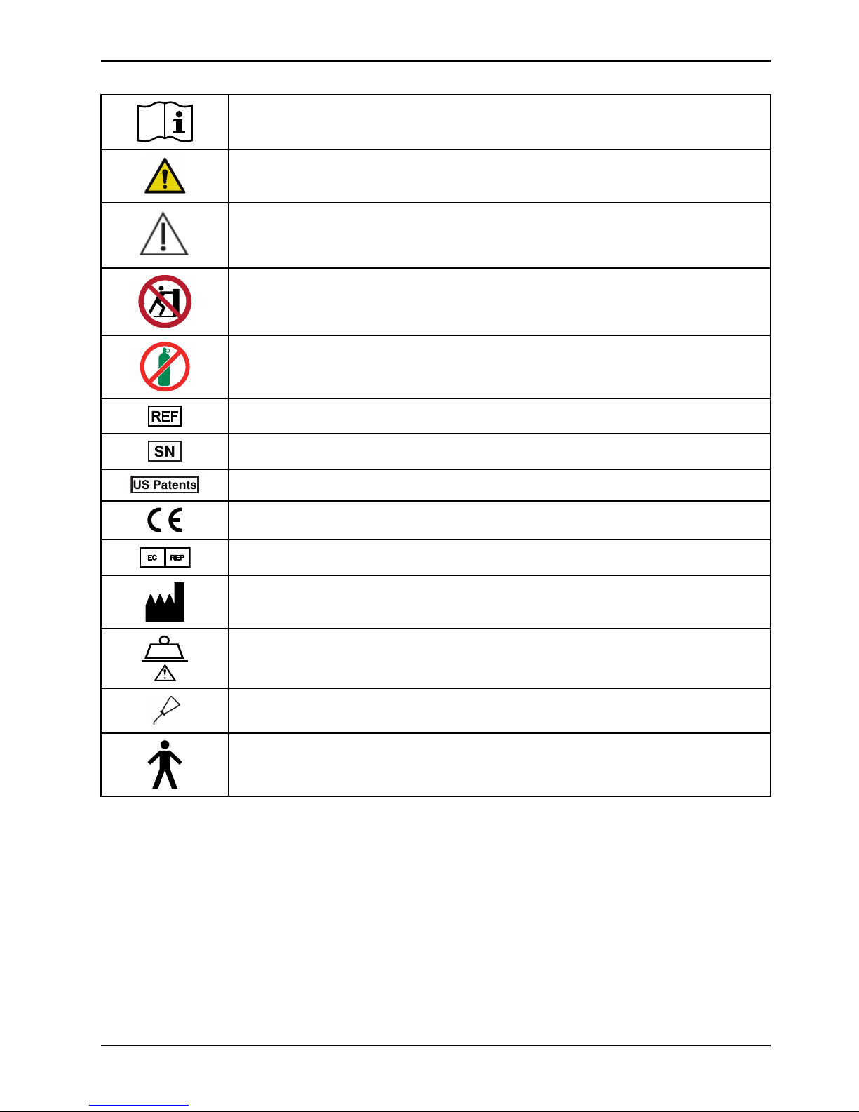
Symbols
Operating instructions
General warning
Caution
No pushing
Do not store the oxygen bottle
Catalogue number
Serial number
For US Patents see www.stryker.com/patents
CE mark
EC REP
Manufacturer
Safe working load
Lubricate
Type B applied part
www.stryker.com 1089-109-001 REV A
Page 4

sample text
Page 5

Table of Contents
Warning/Caution/Note Definition ... .. .. ............. .. ............. .. .. ............. .. ............. .. .. ............. .. ............. .. .. ...........3
Summary of safety precautions... .. ............... .. ............. .. ............... .. ............. .. ............... .. ............. .. ............... 4
Introduction......... .. ............. .. .. ............. .. ............. .. .. ............. .. ............. .. .. ............. .. ............. .. .. ............. .. ...6
Product description.. ............. ............... .. .. ............. .. ............. .. .. ............. .. ............. .. .. ............. .. ............. 6
Indications for use .......... .. ............... .. ............. .. .. ............. .. ............. .. .. ............. .. ............... .. ............. .. .. 6
Expected service life. .. ............. .. ............. .. .. ............. .. ............. .. .. ............. .. ............. .. .. ............. .. .......... 6
Contraindications ...... .. .. ............... ............. .. .. ............... ............... .. ............... .. ............. .. ............... .. .....6
Specifications.......... .. ............. .. .. ............. .. ............. .. .. ............. .. ............. .. .. ............. .. ............. .. .. ........ 6
Product illustration........... .. ............. .. .. ............. .. ............. .. .. ............. .. ............. .. .. ............. .. ............... .. .8
Contact information .............. ............... .. ............... ............... .. .. ............. .. ............. .. .. ............. .. ............. 9
Serial number location ............. .. .. ............. .. ............. .. .. ............... ............. .. .. ............... ............... .. .. .... 10
Date of manufacture .. ............... .. ............. .. ............... .. ............. .. .. ............. .. ............. .. .. ............. .. ....... 10
Setup.......... .. .. ............. .. ............. .. .. ............. .. ............. .. .. ............. .. ............. .. .. ............. .. ............. .. .. ...... 11
Operation ...... .. ............... .. ............... ............... .. ............... ............... .. .. ............. ............... .. .. ............. .. .... 12
Applying and releasing the brakes ......... .. .. ............. .. ............. .. .. ............. .. ............. .. .. ............. .. ............ 12
Raising or lowering the litter.... .. ............... .. ............. .. .. ............. .. ............. .. .. ............. .. ............. .. .. ......... 12
Positioning the product in Trendelenburg.. .. .. ............. .. ............. .. .. ............. .. ............. .. .. ............. .. ........... 13
Positioning the product in Reverse Trendelenburg.......... .. ............. .. .. ............. .. ............. .. .. ............. .. ........ 14
Transporting a patient with the retractable fifth wheel .......... .. ............... ............... .. .. ............. ............... .. .. . 14
Raising or lowering the siderails ..... ............... .. ............... ............... .. .. ............. .. ............. .. .. ............. .. .... 14
Raising or lowering the Fowler backrest .. ............. .. ............. .. .. ............. .. ............. .. .. ............. .. ............... . 15
Raising or lowering the Fowler backrest or the gatch with the crank option .. ............. .. .. ............. .. ............. .. .. . 16
Positioning the enhanced clearance headpiece .......... .. ............. .. .. ............. .. ............. .. .. ............. .. ........... 16
Storing objects in the base hood........... .. ............. .. .. ............. .. ............. .. .. ............. .. ............. .. .. ............. 16
Accessories .. ............. .. .. ............. .. ............. .. .. ............. .. ............. .. .. ............. .. ............... .. ............. .. ......... 18
Transferring a patient with the patient transfer board............. .. ............. .. .. ............. .. ............. .. .. ............. .. . 19
Hanging devices from the surgery accessory rail ..... .. ............. .. ............... .. ............. .. .. ............. .. ............. . 20
Attaching the adjustable arm board......... .. .. ............. .. ............. .. .. ............. .. ............. .. .. ............. .. ........... 20
Installing and removing the pre-op-post-op head extension (crank Fowler backrest only) ...... ............... .. .. ........ 20
Positioning the wrist rest .... .. ............. .. .. ............. .. ............. .. .. ............. .. ............. .. .. ............. .. ............. .. 21
Installing the drape support and air delivery system ............. .. .. ............. .. ............. .. .. ............. .. ............. .. .. . 21
Positioning or stowing the push handles (optional) ........... .. ............... .. ............. .. ............... .. ............. .. .. .... 22
Attaching the defibrillator tray ............ .. ............. .. .. ............. .. ............. .. .. ............. .. ............. .. .. ............. .. 23
Converting the defibrillator tray/foot extender to a defibrillator tray . .. ............... .. ............. .. ............... .. .......... 23
Converting the defibrillator tray/foot extender to a foot extender ... .. .. ............. .. ............. .. .. ............. .. ........... 24
Attaching the footboard/chart holder .. .. .. ............. .. ............. .. .. ............. .. ............. .. .. ............. .. ............... . 25
Positioning the two-stage permanently attached IV pole option .. .. ............. .. ............. .. .. ............. .. ............... . 25
Positioning the three-stage permanently attached IV pole option .. ............... .. ............. .. .. ............. .. ............. . 26
Attaching and positioning the removable IV pole .......... .. ............. .. ............... .. ............. .. ............... .. .......... 27
Attaching the upright oxygen bottle holder .... .. ............... .. ............. .. .. ............. .. ............... .. ............. .. .. ..... 28
Extending or stowing the serving tray holder/footboard.... .. .. ............. .. ............. .. .. ............... ............. .. .. ...... 29
Attaching the siderail pads ............ .. .. ............. .. ............. .. .. ............. .. ............. .. .. ............. .. ............. .. .. .. 29
Locating the patient restraint strap tie-ins ............... ............. .. .. ............... ............... .. .. ............. ............... . 29
www.stryker.com 1089-109-001 REV A 1
Page 6

Table of Contents
Cleaning and disinfecting with wipes ..... .. .. ............. .. ............. .. .. ............. .. ............. .. .. ............. .. ............. .. .. .. 31
Cleaning............ .. ............. .. .. ............. .. ............. .. .. ............. .. ............. .. .. ............. .. ............. .. .. ............. .. .. 32
Cleaning the product. .. ............. .. ............. .. .. ............. .. ............. .. .. ............. .. ............. .. .. ............. .. ........ 32
Cleaning the mattress ... .. ............. .. ............. .. .. ............. .. ............... .. ............. .. ............... .. ............. .. .. .. 32
Remove iodine.............. .. ............. .. ............... .. ............. .. .. ............. .. ............. .. .. ............. .. ............. .. .. . 33
Special instructions ...... .. .. ............. .. ............. .. .. ............. .. ............. .. .. ............. .. ............. .. .. ............. .. .. 33
Disinfecting......... .. ............. .. .. ............. .. ............. .. .. ............. .. ............. .. .. ............. .. ............. .. .. ............. .. . 34
Disinfecting the product............. .. ............... ............... .. ............... ............... .. .. ............. .. ............. .. .. ..... 34
Disinfecting the mattress .. ............. .. ............... .. ............. .. .. ............. .. ............. .. .. ............. .. ............. .. .. . 34
Preventive maintenance ... ............... .. ............. .. ............... .. ............. .. ............... .. ............. .. ............... .. ....... 36
Lubrication points..... .. .. ............. .. ............... .. ............. .. ............... .. ............. .. ............... .. ............. .. ...... 37
2 1089-109-001 REV A www.stryker.com
Page 7

Warning/Caution/Note Definition
The words WARNING, CAUTION, and NOTE carry special meanings and should be carefully reviewed.
WARNING
Alerts the reader about a situation which, if not avoided, could result in death or serious injury. It may also describe
potential serious adverse reactions and safety hazards.
CAUTION
Alerts the reader of a potentially hazardous situation which, if not avoided, may result in minor or moderate injury to the
user or patient or damage to the product or other property. This includes special care necessary for the safe and
effective use of the device and the care necessary to avoid damage to a device that may occur as a result of use or
misuse.
Note: Provides special information to make maintenance easier or important instructions clearer.
www.stryker.com 1089-109-001 REV A 3
Page 8

Summary of safety precautions
Carefully read and strictly follow the warnings and cautions listed on this page. Service only by qualified personnel.
WARNING
• Always allow the product to reach room temperature before you set up the product or test functional operations.
Permanent product damage may occur.
• Always operate the product when all operators are clear of the mechanisms.
• Always apply the brakes when a patient is getting on the product or off the product or when the product is not
moving. Injury could result if the product moves while a patient is getting on the product or off the product.
• Always put the product in the lowest position with the siderails up and latched when you leave a patient unattended
on the product. Do not leave the product at a higher height.
• Always remove any devices that may be in the way before you raise or lower the litter.
• Do not sit on the end of the product. The product may tip.
• Always keep patient and operator extremities away from siderail spindles when you raise or lower the siderail.
• Always unplug the power cord from the wall outlet before you transport or clean the product if your product is
equipped with the electric lift or electric litter option.
• Always lock the siderails in the full up position with the sleep surface flat in the lowest position when you transport a
patient.
• Always put the product in the lowest position with the siderails up and latched when you leave a patient unattended
on the product. Do not leave the product at a higher height.
• Always lock the siderails in the full up position with the sleep surface horizontal in the lowest position when you
transport a patient.
• Always keep the patient’s limbs away from the siderail spindles when you lower the siderail.
• Do not allow the siderails to lower on their own.
• Always keep hands and fingers clear of the Fowler backrest release handles and the Fowler backrest frame when
you lower the Fowler backrest.
• Always use caution when you raise a pneumatic Fowler backrest while a patient is on the product. Use proper lifting
techniques and get assistance, if necessary.
• Always support the patient’s head when you position the headpiece or the Fowler backrest. Patient injury may occur.
• Do not reach between the side of the head extension and the articulating headpiece to pull the release handles.
Operator injury may occur.
• Always keep fingers away from jointed areas when you adjust the headpiece. Operator injury may occur.
• Always apply the brakes on both the product with the patient and the product the patient will be transferred to
before you transfer a patient from one patient support platform (bed, stretcher, gurney, operating table) to another
patient support platform.
• Always make sure that the patient support platforms are the same height before you transfer a patient.
• Always make sure that the transfer board is secure on both patient support platforms.
• Do not place items that weigh more than 30 lb (14 kg) on the defibrillator tray. Always strap down all devices that
you place on the defibrillator tray.
• Always use caution if the defibrillator tray/foot extender, footboard/chart holder, or upright oxygen bottle holder is
attached to avoid pinching your fingers when you position the foot end push handle option.
• Do not place items that weigh more than 30 lb (14 kg) on the defibrillator tray/foot extender. Always strap down all
devices that you place on the defibrillator tray.
• Do not use the IV pole as a push/pull device. Product damage may occur.
• Do not place objects that exceed 40 lb (18 kg) in the upright oxygen bottle holder.
• Do not place objects that exceed 30 lb (14 kg) on the serving tray.
4 1089-109-001 REV A www.stryker.com
Page 9

Summary of safety precautions
WARNING (CONTINUED)
• Always use caution when you attach the restraint straps to avoid potential injury to both patients and operators.
Physical restraints, even if properly secured, may result in serious harm to patients and operators, including
entanglement, entrapment, physical injury, or death.
• Only attach restraint straps or devices at the identified attachment points of the product. Failure to do so may result
in patient or operator injury. Do not attach restraints straps to the siderail.
• Always refer to the applicable state and federal restrictions and the appropriate facility protocols before you use
any restraint strap or device.
• Do not clean, service, or perform maintenance while the product is in use.
• Do not immerse the mattress in cleaning or disinfectant solutions. Excess moisture could cause product
malfunction that results in product damage or patient injury.
• Do not allow fluid to pool on the mattress. Fluids can cause corrosion of components and may cause the safety and
performance of this product to become unpredictable.
• Always inspect mattress covers for tears, punctures, excessive wear, and misaligned zippers every time you clean
the covers. Remove and replace a damaged mattress immediately to prevent cross-contamination.
• Do not steam clean, pressure wash, hose off, or ultrasonically clean mattresses. These methods of cleaning may
void this product’s warranty.
• Always disinfect the mattress between patients. Failure to do so could result in cross-contamination and infection.
CAUTION
• Improper usage of the product can cause injury to the patient or operator. Operate the product only as described in
this manual.
• Do not modify the product or any components of the product. Modifying the product can cause unpredictable
operation resulting in injury to patient or operator. Modifying the product also voids its warranty.
• Do not place objects that exceed 60 lb (27 kg) in the base hood.
• Do not sit, step, or stand on the base hood.
• Always raise the IV pole before you attach the defibrillator tray/foot extender to the product. If you do not raise the
IV pole, the foot extender will not operate.
www.stryker.com 1089-109-001 REV A 5
Page 10

Introduction
This manual assists you with the operation or maintenance of your Stryker product. Read this manual before operating
or maintaining this product. Set methods and procedures to educate and train your staff on the safe operation or
maintenance of this product.
CAUTION
• Improper usage of the product can cause injury to the patient or operator. Operate the product only as described in
this manual.
• Do not modify the product or any components of the product. Modifying the product can cause unpredictable
operation resulting in injury to patient or operator. Modifying the product also voids its warranty.
Notes
• This manual is a permanent part of the product and should remain with the product even if the product is sold.
• Stryker continually seeks advancements in product design and quality. This manual contains the most current
product information available at the time of printing. There may be minor discrepancies between your product and
this manual. If you have any questions, contact Stryker Customer Service or Technical Support at 1-800-327-0770.
Product description
The Stryker Model 1089 Eye Surgery Stretcher is a general purpose patient transport and treatment stretcher.
Indications for use
The Stryker Medical Eye Surgery Stretcher is a non-powered, wheeled device which consists of a platform mounted on
a wheeled frame that is designed to support patients in a horizontal position. The device has siderails and has the option
available to support the temporary or permanent placement of I.V. poles. The Eye Surgery Stretcher provides the
caregiver a method of transporting patients within a healthcare facility and may also be used for minor procedures and
short-term stay (treatment and recovery).
Expected service life
The Stryker Model 1089 Eye Surgery Stretcher has a 10 year expected service life under normal use conditions and
with appropriate periodic maintenance.
Contraindications
None known.
Specifications
Safe working load indicates the sum of the patient, mattress and
accessory weight
500 lb 225 kg
Overall length
Overall width
Height
High 34 in. 86.4 cm
6 1089-109-001 REV A www.stryker.com
90 in. 228.6 cm
31.5 in. 80 cm
Page 11

Specifications (Continued)
Low 22.25 in. 56.5 cm
Litter positioning
Backrest 0° to 90°
Knee gatch 0° to 30°
Trendelenburg/Reverse Trendelenburg ±18°
Introduction
Patient surface
Siderails
Minimum under product clearance 6 in. nominal
Stryker reserves the right to change specifications without notice.
26 in. x 87 in. 66 cm x 221 cm
13 in. x 55 in. 33 cm x 139.5 cm
1.75 in. under the
hydraulic cylinders
and fifth wheel
15 cm
4.5 cm
www.stryker.com 1089-109-001 REV A 7
Page 12
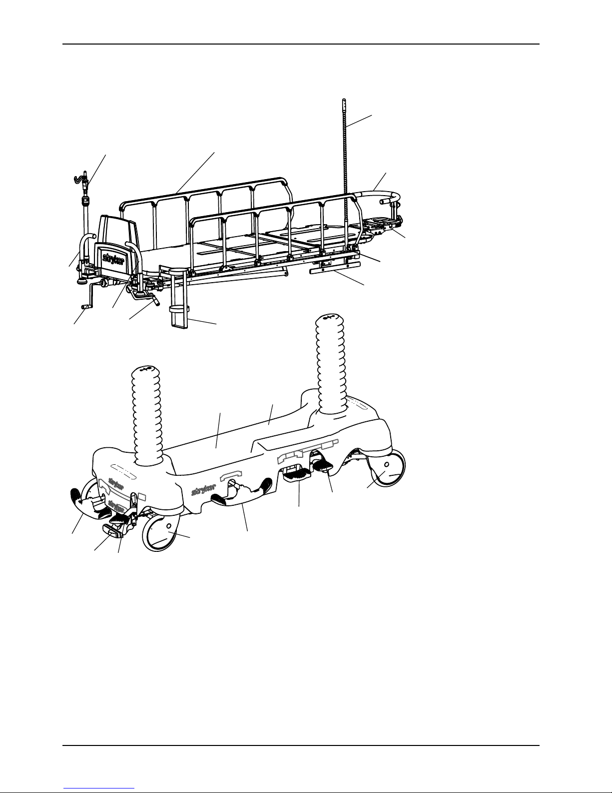
Product illustration
B
C
D
E
F
G
H
I
K
L
M
N
O
P
Q
J
A
B
C
E
L
R
Introduction
8 1089-109-001 REV A www.stryker.com
Page 13

Product illustration (Continued)
Introduction
A
B
C Caster L
D
E
F
G Gatch crank handle P
H Head extension
I
Base hood storage area
Brake/steer pedal
Drape support and air delivery system
Foot end push handles
Fowler backrest crank handle O
Hydraulic release pedal
J
K
M Siderail
N Siderail latch
Q
R Wrist rest
IV pole
Oxygen bottle cutout
Pump pedal
Surgery accessory rail
Uni-lower pedal
Upright oxygen bottle holder
Contact information
Contact Stryker Customer Service or Technical Support at: 1-800-327-0770.
Stryker Medical
3800 E. Centre Avenue
Portage, MI 49002
USA
To view your operations or maintenance manual online, see https://techweb.stryker.com/.
Have the serial number (A) of your Stryker product available when calling Stryker Customer Service or Technical
Support. Include the serial number in all written communication.
www.stryker.com 1089-109-001 REV A 9
Page 14

Serial number location
A
Introduction
Date of manufacture
The year of manufacture is the first 2 digits of the serial number.
10 1089-109-001 REV A www.stryker.com
Page 15

Setup
To unpack your product, see the unpacking instructions that are attached to the product inside of the shipping crate.
WARNING
• Always allow the product to reach room temperature before you set up the product or test functional operations.
Permanent product damage may occur.
• Always operate the product when all operators are clear of the mechanisms.
Make sure that the product is working before you put the product into service.
1. Press down on the brake pedal to apply the brakes. Make sure that all four casters are locked.
2. Raise and lower the litter.
3. Raise the product to the highest height. Put the product in the Trendelenburg position. Make sure that the head end
lowers to the lowest position.
4. Raise the product to the highest height. Put the product in the Reverse Trendelenburg position. Make sure that the
foot end lowers to the lowest position.
5. Apply the fifth wheel to make sure that the fifth wheel is guides and pivots the product.
6. Make sure that the siderails raise, lower, and lock in place.
7. Raise and lower the Fowler backrest (head end).
8. Rotate the headpiece in both directions to make sure that the headpiece adjusts to all positions.
www.stryker.com 1089-109-001 REV A 11
Page 16

Operation
Applying and releasing the brakes
WARNING
Always apply the brakes when a patient is getting on the product or off the product or when the product is not moving.
Injury could result if the product moves while a patient is getting on the product or off the product.
To apply the brakes, push down on the brake (red) side of the brake/steer pedal. Push on the product to make sure that
the brakes work.
To release the brakes, push down on the steer (green) side of the brake/steer pedal.
Raising or lowering the litter
WARNING
• Always put the product in the lowest position with the siderails up and latched when you leave a patient unattended
on the product. Do not leave the product at a higher height.
• Always remove any devices that may be in the way before you raise or lower the litter.
• Do not sit on the end of the product. The product may tip.
• Always keep patient and operator extremities away from siderail spindles when you raise or lower the siderail.
To raise the litter, press down on the pump pedal (A) until you achieve the desired height (Figure 1 on page 13).
To lower the entire litter, press on the center of the uni-lower pedal (C).
To lower the head end of the litter, press down on the foot end release pedal (D) or press on the side of the uni-lower
pedal (C) closest to the head end of the product.
To lower the foot end of the litter, press down on the foot end release pedal (B) or press on the side of the uni-lower
pedal (C) closest to the foot end of the product.
12 1089-109-001 REV A www.stryker.com
Page 17

Operation
A
B
C
D
AC
A
A
B
D
E
Raising or lowering the litter (Continued)
Figure 1: Raising or lowering the litter
Positioning the product in Trendelenburg
WARNING
Always remove any devices that may be in the way before you raise or lower the litter.
CAUTION
Do not use the hydraulics on the base to raise the product with a patient lift under the product.
To position the product in the Trendelenburg position (head down), Raise the litter (Raising or lowering the litter on page
12).
Note: Raise the litter to the highest height for a greater Trendelenburg angle.
To lower the head end of the product, press down on the foot end release pedal (D) or press down on the side of the unilower pedal (C) closest to the head end until the litter is flat (Figure 1 on page 13).
To lower the product from Trendelenburg position, press down on the foot end release pedals (B and D) at the same
time or press down on the center of the uni-lower pedal (C) until the litter is flat.
www.stryker.com 1089-109-001 REV A 13
Page 18

Operation
Positioning the product in Reverse Trendelenburg
WARNING
Always remove any devices that may be in the way before you raise or lower the litter.
CAUTION
Do not use the hydraulics on the base to raise the product with a patient lift under the product.
To position the product in the Reverse Trendelenburg position (foot down), raise the litter to the highest height (Raising
or lowering the litter on page 12).
To lower the foot end of the product, press down on the foot end release pedal (B) or press down on the side of the unilower pedal (C) to the foot end (Figure 1 on page 13).
To lower the product from Reverse Trendelenburg position, press down on the foot end release pedals (B and D) at the
same time or press down on the center of the uni-lower pedal (C) until the litter is flat.
Transporting a patient with the retractable fifth wheel
WARNING
• Always position the patient in the center of the product.
• Always remove any devices that may be in the way before you raise or lower the litter.
• Always unplug the power cord from the wall outlet before you transport or clean the product if your product is
equipped with the electric lift or electric litter option.
• Always lock the siderails in the full up position with the sleep surface flat in the lowest position when you transport a
patient.
CAUTION
Do not use the hydraulics on the base to raise the product with a patient lift under the product.
To transport a patient with the retractable fifth wheel:
1. Push down on the steer side of the brake/steer pedal to apply the fifth wheel.
2. Put the pedal in the neutral position to move the product laterally. Move the product to the desired location.
Note: Do not attempt to move the product laterally with the retractable fifth wheel applied.
3. Apply the brakes to lock the product in place.
Note: Always make sure that the brake is released before you move the product to avoid operator or patient injury.
Raising or lowering the siderails
WARNING
• Always put the product in the lowest position with the siderails up and latched when you leave a patient unattended
on the product. Do not leave the product at a higher height.
• Always lock the siderails in the full up position with the sleep surface horizontal in the lowest position when you
transport a patient.
• Always keep the patient’s limbs away from the siderail spindles when you lower the siderail.
14 1089-109-001 REV A www.stryker.com
Page 19

Operation
A
A
Raising or lowering the siderails (Continued)
WARNING (CONTINUED)
• Do not allow the siderails to lower on their own.
To raise the siderails, use two hands to grasp the siderail. Raise the siderail until the release latch clicks into place. Pull
on the siderail to make sure that the siderail is locked.
To lower the siderails, pull up on the release latch. Guide the siderail to the lowest position.
Note: Do not use siderails as restraint devices to keep the patient from exiting the product. The siderails keep the
patient from rolling off the product. The operator must determine the degree of restraint necessary to make sure that the
patient is safe.
Raising or lowering the Fowler backrest
WARNING
• Always keep hands and fingers clear of the Fowler backrest release handles and the Fowler backrest frame when
you lower the Fowler backrest.
• Always use caution when you raise a pneumatic Fowler backrest while a patient is on the product. Use proper lifting
techniques and get assistance, if necessary.
To raise the Fowler backrest, squeeze the Fowler backrest release handles (A). Pull the Fowler backrest up to the
desired position (Figure 2 on page 15 ).
To lower the Fowler backrest, squeeze the Fowler backrest release handles (A). Push the Fowler backrest down to the
desired position.
www.stryker.com 1089-109-001 REV A 15
Figure 2: Fowler backrest
Page 20

Operation
A
B
Raising or lowering the Fowler backrest or the gatch with the crank option
To raise the Fowler backrest, turn the crank handle clockwise.
To lower the Fowler backrest, turn the crank handle counterclockwise.
To raise the gatch, turn the crank handle clockwise.
To lower the gatch, turn the crank handle counterclockwise.
Note: The Fowler backrest and gatch crank handles are stored under the litter. Pivot the crank out and push in to
secure the crank rod.
Positioning the enhanced clearance headpiece
WARNING
• Always support the patient’s head when you position the headpiece or the Fowler backrest. Patient injury may occur.
• Do not reach between the side of the head extension and the articulating headpiece to pull the release handles.
Operator injury may occur.
• Always keep fingers away from jointed areas when you adjust the headpiece. Operator injury may occur.
To adjust the articulating headpiece:
1. Squeeze right handle (A) under the head section to release the latch. Rotate the headpiece on axis “A” (head)
(Figure 3 on page 16).
Figure 3: Positioning the articulating headpiece
2. Squeeze left handle (B) under the head section to release the latch. Rotate the head section on axis “B” (neck).
Note: For ease of use, release only one latch at a time.
Storing objects in the base hood
CAUTION
• Do not place objects that exceed 60 lb (27 kg) in the base hood.
• Do not sit, step, or stand on the base hood.
16 1089-109-001 REV A www.stryker.com
Page 21

Operation
Storing objects in the base hood (Continued)
You can store patient belongings in the base hood. Do not use the oxygen bottle holder cutout to store oxygen bottles or
patient belongings.
www.stryker.com 1089-109-001 REV A 17
Page 22

Accessories
These accessories may be available for use with your product. Confirm availability for your configuration or region. Call
Stryker Customer Service: 1-800-327-0770.
Name Part number
Air delivery and drape support 1068-168-000
Armboard clamp, adjustable 1068-056-000
Defibrillator tray
Defibrillator tray/foot extender/footboard
EURO accessory rail, bolt on
EURO accessory rail, bolt on
Footboard/chart holder 1105-045-500
IV pole, 2-stage, permanent 1089-080-000
IV pole, 3-stage, permanent 1089-062-000
IV pole, removable 0390-025-010
Oxygen bottle holder, upright
Oxygen bottle retainer
Push handles, bolt on, foot end
Restraint strap, body 0390-019-000
Restraint strap, chest 1010-058-000
Restraint strap, full package
Restraint strap, package 0785-045-010
Restraint strap, wrist 0946-044-000
1105-045-200
1105-045-400
1089-600-120
1089-600-130
1089-030-000
1037-010-090
1089-700-010
1010-077-000
Serving tray
Serving tray holder/footboard
Siderail pads
Surgery accessory rail
UC concave pad (blue), 3
UC flat pad (blue), 3
Wrist rest, superior 1068-250-000
Wrist rest, temporal 1068-251-000
1105-045-700
1105-045-800
1010-052-000
1089-266-000
1069-181-000
1069-180-000
18 1089-109-001 REV A www.stryker.com
Page 23

Accessories
AB
C
Transferring a patient with the patient transfer board
WARNING
• Always apply the brakes on both the product with the patient and the product the patient will be transferred to
before you transfer a patient from one patient support platform (bed, stretcher, gurney, operating table) to another
patient support platform.
• Always make sure that the patient support platforms are the same height before you transfer a patient.
• Always make sure that the transfer board is secure on both patient support platforms.
To transfer a patient with a patient transfer board:
1. Apply the brakes. Push on the product to make sure that the brakes work.
2. Lower the siderail (A) to the lowest position (Figure 4 on page 19).
3. Raise the transfer board (C) from the bottom while you lift from the top.
Note: The transfer board (C) is located between the siderail (A) and the mattress (B) (Figure 4 on page 19).
4. Pivot the board downward onto the mating support surface.
5. Transfer the patient to the mating support surface.
Figure 4: Transfer the patient
www.stryker.com 1089-109-001 REV A 19
Page 24

Accessories
A
Hanging devices from the surgery accessory rail
You can use the surgery accessory rail to hang devices such as pumps, Foley bags, or monitors on either side of the
product.
Attaching the adjustable arm board
You can use the adjustable arm board to rest a patient’s arm during a minor procedure.
To attach the arm board:
1. Slide the direct clamp onto the surgery accessory rail.
2. Insert the bar-leg support into the hole in the top of the direct clamp.
3. Tighten the clamp to secure the arm board in place.
4. Rotate the arm board to the desired position and lock in place. Make sure that the arm board is secure before you
place the patient’s arm on the arm board.
Installing and removing the pre-op-post-op head extension (crank Fowler
backrest only)
1. To install the extension on the litter, slide the extension tube into the receptacle tube on the side of the Fowler
frame. Pivot the extension upward until the extension locks in place on the headpiece frame.
2. To remove the extension from the litter, pull the red knob (A) under the extension toward you (Figure 5 on page 20).
Rotate the extension downward and pull the extension straight out of the socket.
Notes
• The pre-op and post-op head extensions provide additional litter surface to protect the patient’s head during
transport.
• The head extension can be used as push handles when you move the product.
20 1089-109-001 REV A www.stryker.com
Figure 5: Red knob location
Page 25

Accessories
A
B
C
D
A
B
C
D
Positioning the wrist rest
There are two optional wrist rests available:
• Standard (1)
• Temporal (2)
To position the wrist rest (Figure 6 on page 21):
1. Insert the support tube (A) into the socket in the Fowler backrest head piece assembly.
2. Turn the knob (B) clockwise to secure the wrist rest assembly.
3. Turn the knob (C) counterclockwise to loosen it.
4. Raise or lower the wrist rest to the desired height.
5. Turn the knob clockwise to tighten the knob and hold the wrist rest in place.
Note: The “U” shaped rest (D) can be pivoted up and away from the patient when the wrist rest is not in use.
Installing the drape support and air delivery system
The optional drape support air delivery system has a flexible drape support with air tubing inside the support for patient
comfort.
1. Place the mounting tab (A) into the IV socket at the head end of the product.
www.stryker.com 1089-109-001 REV A 21
Figure 6: Installing and positioning the wrist rests
Page 26

Accessories
A
B
Installing the drape support and air delivery system (Continued)
2. Insert the air delivery tube into the air tube receptacle (B) (Figure 7 on page 22).
Note: The maximum PSI level for the drape support/oxygen tubing is 20 PSI (1.38 Bars/140 KPA).
Figure 7: Air delivery tubing
Positioning or stowing the push handles (optional)
To position or stow the push handles:
1. Pivot the handles up from the end of the product (Figure 8 on page 22).
2. Push down on the handles to lock them into position.
3. Reverse steps to stow the handles.
Note: Only use the push handles as push or pull devices unless otherwise specified to avoid product damage.
Figure 8: Positioning the head end push handles
22 1089-109-001 REV A www.stryker.com
Page 27

Accessories
Attaching the defibrillator tray
WARNING
• Do not place items that weigh more than 30 lb (14 kg) on the defibrillator tray. Always strap down all devices that
you place on the defibrillator tray.
• Always use caution if the defibrillator tray/foot extender, footboard/chart holder, or upright oxygen bottle holder is
attached to avoid pinching your fingers when you position the foot end push handle option.
To attach the defibrillator tray:
1. Insert the defibrillator tray pins into the sockets at the foot end of the product.
2. Use the strap to secure devices to the defibrillator tray.
Notes
• Do not use the defibrillator tray as a push/pull device. Product damage may occur.
• Always raise the foot end push handles when you use accessories (such as the defibrillator tray/foot extender,
footboard/chart holder, upright oxygen bottle holder) or the accessories will not function.
Converting the defibrillator tray/foot extender to a defibrillator tray
WARNING
• Do not place items that weigh more than 30 lb (14 kg) on the defibrillator tray/foot extender. Always strap down all
devices that you place on the defibrillator tray.
• Always use caution if the defibrillator tray/foot extender, footboard/chart holder, or upright oxygen bottle holder is
attached to avoid pinching your fingers when you position the foot end push handle option.
CAUTION
Always raise the IV pole before you attach the defibrillator tray/foot extender to the product. If you do not raise the IV
pole, the foot extender will not operate.
To convert the defibrillator tray/foot extender to a defibrillator tray:
1. Pull out the top knob (A) (Figure 9 on page 24).
2. Pivot the defibrillator tray (B) until the tray is flat over the foot end of the product. Release the top knob (A). Make
sure that the defibrillator tray is locked in place.
3. Use the strap to secure devices to the defibrillator tray.
Notes
• Do not use the defibrillator tray/foot extender as a push/pull device. Product damage may occur.
• Do not attach items to the foot extender.
www.stryker.com 1089-109-001 REV A 23
Page 28

Accessories
A
B
C
D
Converting the defibrillator tray/foot extender to a defibrillator tray (Continued)
Figure 9: Defibrillator tray/foot extender
Converting the defibrillator tray/foot extender to a foot extender
WARNING
• Do not place items that weigh more than 30 lb (14 kg) on the defibrillator tray/foot extender. Always strap down all
devices that you place on the defibrillator tray.
• Always use caution if the defibrillator tray/foot extender, footboard/chart holder, or upright oxygen bottle holder is
attached to avoid pinching your fingers when you position the foot end push handle option.
CAUTION
Always raise the IV pole before you attach the defibrillator tray/foot extender to the product. If you do not raise the IV
pole, the foot extender will not operate.
To convert the defibrillator tray/foot extender to a foot extender (Figure 9 on page 24):
1. Pull out the top knob (A).
2. Pivot the defibrillator tray (B) until the tray locks against the foot extender.
3. Pull out the bottom knob (D) while you hold the defibrillator tray/foot extender assembly.
4. Lower the foot extender (C) until the foot extender is flat.
5. Release the bottom knob (D). Push on the foot extender to make sure that the foot extender is locked in place.
Notes
• Do not use the defibrillator tray/foot extender as a push/pull device. Product damage may occur.
• Do not attach items to the foot extender.
24 1089-109-001 REV A www.stryker.com
Page 29

Accessories
Attaching the footboard/chart holder
WARNING
Always use caution if the defibrillator tray/foot extender, footboard/chart holder, or upright oxygen bottle holder is
attached to avoid pinching your fingers when you position the foot end push handle option.
To attach the footboard/chart holder, insert the footboard/chart holder pins into the sockets at the foot end of the
product.
Note: Do not use the footboard/chart holder as a push/pull device. Product damage may occur.
Positioning the two-stage permanently attached IV pole option
WARNING
Do not use the IV pole as a push/pull device. Product damage may occur.
You can purchase the product with the two-stage IV pole option permanently attached at the head end, foot end, or both
ends of the product. The IV pole is equipped with a telescopic pole that extends to provide a second height position. You
can fold and store the IV pole when not in use.
To position the two-stage IV pole (Figure 10 on page 26):
1. Lift and pivot the pole from the storage position.
2. Push the IV pole down until the IV pole locks in place.
3. To raise the height of the IV pole, pull up on the telescoping portion (A) until the pole locks in place at the fully
raised position.
4. Rotate the IV hangers (B) to the desired position and hang the IV bags.
5. To lower the IV pole, hold the telescoping portion of the IV pole, turn the latch (C), and lower the telescoping portion.
Notes
• Do not hang IV bags that exceed 40 lb (18 kg) on the IV pole.
• Always make sure that the IV pole is at a low height to pass safely through door openings when you transport a
patient.
www.stryker.com 1089-109-001 REV A 25
Page 30

Accessories
A
B
C
A
Positioning the two-stage permanently attached IV pole option (Continued)
Figure 10: Positioning the 2 stage permanently attached IV pole
Positioning the three-stage permanently attached IV pole option
WARNING
Do not use the IV pole as a push/pull device. Product damage may occur.
You can purchase the product with the three-stage IV pole option permanently attached at the head end, foot end, or
both ends of the product. The IV pole is equipped with a telescopic pole that extends to provide a second and third
height position. You can also fold and store the IV pole when not in use.
To position the three-stage IV pole (Figure 11 on page 27):
1. Lift and pivot the pole from the storage position.
2. Push the IV pole down until the pole locks in place.
3. To raise the height of the IV pole, pull up on the telescoping portion (A) until the pole locks into place at the fully
raised position.
4. For a higher IV pole, pull up on section (B). Release section (B) at any desired height to lock the pole in place.
5. Rotate the IV hangers (C) to the desired position and hang the IV bags.
6. To lower the IV pole, push up on the yellow portion of the grip (D) while holding on to section (B) until the pole
lowers.
7. Turn the latch (E) and lower the IV pole telescoping portion.
Notes
• Do not hang IV bags that exceed 12 lb (5 kg) total for all bags on the IV pole.
• Do not hang IV bags that exceed 9.3 lb (4.2 kg) on a single IV hanger.
• Always make sure that the IV pole is at a low height to allow the pole to pass safely through door openings
when you transport a patient.
26 1089-109-001 REV A www.stryker.com
Page 31

Accessories
A
E
C
B
D
Positioning the three-stage permanently attached IV pole option (Continued)
Figure 11: Positioning the three-stage permanently attached IV pole
Attaching and positioning the removable IV pole
WARNING
Do not use the IV pole as a push/pull device. Product damage may occur.
To attach and position the removable IV pole (Figure 12 on page 28):
1. Insert the IV pole into a socket at the head end or foot end of the product.
2. Turn the knob (A) counterclockwise and pull up on the telescoping portion (B) until you reach the desired height.
3. Turn the knob (A) clockwise to lock the telescoping portion in place.
Notes
• Do not hang IV bags that exceed 40 lb (18 kg) on the IV pole.
• Always make sure that the IV pole is at a low height to pass through door openings when you transport a patient.
www.stryker.com 1089-109-001 REV A 27
Page 32

Accessories
A
B
Attaching and positioning the removable IV pole (Continued)
Figure 12: Removable IV pole
Attaching the upright oxygen bottle holder
WARNING
• Do not place objects that exceed 40 lb (18 kg) in the upright oxygen bottle holder.
• Always use caution if the defibrillator tray/foot extender, footboard/chart holder, or upright oxygen bottle holder is
attached to avoid pinching your fingers when you position the foot end push handle option.
The upright oxygen bottle holder supports an oxygen bottle in a vertical position.
To attach the upright oxygen bottle holder:
1. Insert the support bar into any of the IV sockets.
2. Insert the cotter pin through the hole in the support bar to secure the bottle holder to the product.
Note: Do not use the upright oxygen bottle holder as a push/pull device.
28 1089-109-001 REV A www.stryker.com
Page 33

Accessories
Extending or stowing the serving tray holder/footboard
WARNING
Do not place objects that exceed 30 lb (14 kg) on the serving tray.
To fit the serving tray on the siderail, pull out on both sides of the serving tray and position the tray over the siderails.
To stow the serving tray:
1. Remove the serving tray from the siderails.
2. Push in the sides of the serving tray.
3. Store the serving tray in the footboard.
Note: Do not use the serving tray/footboard as a push/pull device.
Attaching the siderail pads
To attach the siderail pads:
1. Tuck the siderail pad between the mattress and the siderail.
2. Fasten the Velcro® straps around the top of the siderail to secure the siderail pad.
Locating the patient restraint strap tie-ins
WARNING
• Always use caution when you attach the restraint straps to avoid potential injury to both patients and operators.
Physical restraints, even if properly secured, may result in serious harm to patients and operators, including
entanglement, entrapment, physical injury, or death.
• Only attach restraint straps or devices at the identified attachment points of the product. Failure to do so may result
in patient or operator injury. Do not attach restraints straps to the siderail.
• Always refer to the applicable state and federal restrictions and the appropriate facility protocols before you use
any restraint strap or device.
There are six patient restraint strap tie-in locations on the litter assembly for attaching patient restraint straps (Figure 13
on page 30).
www.stryker.com 1089-109-001 REV A 29
Page 34

Accessories
Locating the patient restraint strap tie-ins (Continued)
Figure 13: Restraint strap tie-in locations
30 1089-109-001 REV A www.stryker.com
Page 35

Cleaning and disinfecting with wipes
For United States only. Confirm availability for your configuration or region. Call Stryker Customer Service: 1-800-327-
0770.
Stryker’s preferred wipes (2060-000-001 6'' x 10'' or 2060-000-002 9'' x 12'') include the following active ingredients:
• n-Alkyl (60% C14, 30% C16, 5% C12, 5% C18) dimethyl benzyl ammonium chloride - 0.154%
• n-Alkyl (68% C12, 32% C14) dimethyl ethylbenzyl ammonium chloride - 0.154%
• Isopropanol - 21.000%
Non-active ingredient: Ethylene Glycol Monobutyl Ether - less than 3%
Note: For safety information, read the product label.
To clean or disinfect the external product surface:
1. To clean, wipe external surfaces with a fresh, clean wipe to remove all visible soils. Repeat as necessary until the
product is clean.
Notes
• Use as many wipes as necessary.
• Complete step 1 before you disinfect.
2. To disinfect, wipe external surfaces with a fresh, clean wipe until wet. Allow the external surface to remain wet for
two minutes at room temperature.
3. Allow the product to dry before you return it to service.
www.stryker.com 1089-109-001 REV A 31
Page 36

Cleaning
Cleaning the product
WARNING
Do not clean, service, or perform maintenance while the product is in use.
Recommended cleaning method
1. Follow the cleaning solution manufacturer’s dilution recommendations.
2. Hand wash all surfaces of the product with warm water and mild detergent.
3. Avoid over-saturation and make sure that the product does not stay wet longer than the detergent manufacturer’s
guidelines for proper cleaning.
4. Dry thoroughly. Do not replace the mattress on the product until the product is dry.
5. Check functionality before you return the product to service.
• Raise and lower the product
• Lock and unlock the brake/steer pedal in both positions
• Latch and unlatch the siderails
• Raise and lower the Fowler backrest
• Raise and lower the gatch
• Make sure all components have proper lubrication
• Make sure all labels are intact
Notes
• Some cleaning agents are corrosive in nature and may cause damage to the product if you use them
improperly. If you do not properly rinse and dry the product, a corrosive residue may be left on the surface of
the product that could cause premature corrosion of critical components. Failure to follow these cleaning
instructions may void your warranty.
• Do not steam clean, power wash, hose off, or ultrasonically clean the product. Use of these methods of
cleaning is not recommended and may void the product’s warranty.
• Clean the base hood.
• Clean the bottom of the brake pads to prevent wax or floor remnant buildup.
Cleaning the mattress
WARNING
• Do not clean, service, or perform maintenance while the product is in use.
• Do not immerse the mattress in cleaning or disinfectant solutions. Excess moisture could cause product
malfunction that results in product damage or patient injury.
• Do not allow fluid to pool on the mattress. Fluids can cause corrosion of components and may cause the safety and
performance of this product to become unpredictable.
• Always inspect mattress covers for tears, punctures, excessive wear, and misaligned zippers every time you clean
the covers. Remove and replace a damaged mattress immediately to prevent cross-contamination.
• Do not steam clean, pressure wash, hose off, or ultrasonically clean mattresses. These methods of cleaning may
void this product’s warranty.
The life of the mattress can be affected by an increase in frequency of usage which might include more frequent
cleaning and disinfection.
1. Use a clean, soft cloth to wipe down the entire mattress with a mild soap and water solution to remove foreign
material.
2. Wipe down the mattress with a clean, dry cloth to remove any excess liquid or cleaning agents.
32 1089-109-001 REV A www.stryker.com
Page 37

Cleaning
Cleaning the mattress (Continued)
3. Rinse and dry covers after cleaning.
4. Disinfect as needed with a hospital grade disinfectant after cleaning has been completed (Disinfecting the mattress
on page 34).
5. Check functionality before you return the product to service.
• Raise and lower the product
• Lock and unlock the brake/steer pedal in both positions
• Latch and unlatch the siderails
• Raise and lower the Fowler backrest
• Raise and lower the gatch
• Make sure all components have proper lubrication
• Make sure all labels are intact
Notes
• Do not iron, dry-clean, or tumble dry the mattress, as this will cause malfunction and damage the product.
• The mattress cover must be completely dry before you store, add linens, or place a patient on the mattress to
prevent impairment of the product performance.
• Avoid over-exposure to alcohol or hydrogen peroxide. The cover material will swell.
• Do not allow liquid to seep into the zipper area and watershed cover barrier. Fluids allowed to come in contact
with the zipper may leak into the mattress which could impair the product performance.
Remove iodine
1. Make a solution of 1 to 2 tablespoons of sodium thiosulfate in a pint of warm water. Use the solution to wipe down
the stained area.
2. Clean the stain as soon as possible after the stain occurs.
3. If stains are not immediately removed, allow solution to soak or stand on the mattress before you wipe the mattress.
4. Rinse the mattresses which have been exposed to the solution with clear water before you return the mattresses to
service.
Note: Failure to follow these directions when you use these types of cleaners may void this product’s warranty.
Special instructions
Velcro®
Solids or stains
Hard-to-clean spots Use standard household cleansers or vinyl cleansers and
Laundering Laundering is not recommended. Laundering may
Saturate with disinfectant, rinse with water, and allow the
solution to evaporate.
Use neutral soaps and warm water. Do not use harsh
cleansers, solvents, or abrasive cleaners.
a soft bristle brush on troublesome spots or stains. Presoak dried-on soil.
substantially decrease the useful life of the mattress.
www.stryker.com 1089-109-001 REV A 33
Page 38

Disinfecting
Disinfecting the product
WARNING
• Do not clean, service, or perform maintenance while the product is in use.
• Do not steam clean, hose off, or ultrasonically clean the product. Use of these methods of cleaning is not
recommended and may void the product’s warranty.
Recommended disinfectants
• Quaternaries (active ingredient - ammonium chloride) that contain less than 3% glycol ether
• Phenolic disinfectant (active ingredient - o-phenylphenol)
• Chlorinated bleach solution (5.25% bleach diluted 1 part bleach to 100 parts water which equals 520 ppm available
chlorine (40 mL of a 5.25% bleach solution per 4000 mL water))
• 70% isopropyl alcohol
Recommended disinfection method
1. Follow the disinfectant solution manufacturer’s dilution recommendations.
2. Hand wash all surfaces of the product with a disinfectant solution.
3. Avoid over-saturation and make sure that the product does not stay wet longer than the chemical manufacturer’s
guidelines for proper disinfecting.
4. Dry thoroughly. Do not replace the mattress on the product until the product is dry.
5. Disinfect the Velcro® after every use. Saturate the Velcro® with disinfectant, rinse with water, and allow the
disinfectant to evaporate (appropriate disinfectant is determined by the facility).
6. Check functionality before you return the product to service.
• Raise and lower the product
• Lock and unlock the brake/steer pedal in both positions
• Latch and unlatch the siderails
• Raise and lower the Fowler backrest
• Raise and lower the gatch
• Make sure all components have proper lubrication
• Make sure all labels are intact
Note: Some cleaning agents are corrosive in nature and may cause damage to the product if you use them
improperly. If you do not rinse and dry the product well, a corrosive residue may be left on the surface of the
product that could cause premature corrosion of critical components. Failure to follow these cleaning instructions
may void your warranty.
Disinfecting the mattress
These instructions provide recommended disinfecting methods for the mattress.
WARNING
Always disinfect the mattress between patients. Failure to do so could result in cross-contamination and infection.
Recommended disinfectants:
• Quaternaries (active ingredient - ammonium chloride) that contain less than 3% glycol ether
• Phenolic disinfectant (active ingredient - o-phenylphenol)
• Chlorinated bleach solution (5.25% bleach diluted 1 part bleach to 100 parts water which equals 520 ppm available
chlorine (40 mL of a 5.25% bleach solution per 4000 mL water))
34 1089-109-001 REV A www.stryker.com
Page 39

Disinfecting
Disinfecting the mattress (Continued)
• 70% isopropyl alcohol
1. Make sure that the mattress has been thoroughly cleaned and dried before you apply disinfectants.
2. Wipe down the mattress with a clean, dry cloth to remove any excess liquid or disinfectant.
3. Care must be taken to thoroughly rinse and dry covers after disinfection.
Notes
• The mattress cover must be completely dry before you store or add linens. Failure to remove excess
disinfectant could cause degradation of the cover material.
• Some cleaning agents are corrosive in nature and may cause damage to the product if you use them
improperly. If you do not rinse and dry the product well, a corrosive residue may be left on the surface of the
product that could cause premature corrosion of critical components. Failure to follow these cleaning
instructions may void your warranty.
• Frequent or prolonged exposure to higher concentrations of disinfectant solutions may prematurely age the
cover fabric.
• The use of accelerated hydrogen peroxides or quaternaries that contain glycol ethers may damage the cover.
www.stryker.com 1089-109-001 REV A 35
Page 40

Preventive maintenance
At a minimum, check all items listed during annual preventive maintenance for all Stryker Medical products. You may
need to perform preventive maintenance checks more frequently based on your level of product usage.
Remove product from service before you perform preventive maintenance.
Note: Clean and disinfect the exterior of the mattress before inspection, if applicable.
Inspect the following items:
All welds
All fasteners are secure
Brake mechanism works
Steer function works
Siderails raise, lower, and latch
Casters lock when you apply the brakes
Casters are secure and swivel
Casters are free of wax or debris
Fowler backrest raises, lowers, and latches
Gatch raises, lowers, and latches
Skins are not cracked
Articulating headpiece locks and releases (optional)
Trendelenburg/Reverse Trendelenburg raises and lowers from all locations
IV pole is intact and locks in all positions (optional)
Oxygen bottle holder is intact and opens and closes (optional)
Arm boards are intact and can be secured
Arm board support levers are intact and latch
Accessories and mounting hardware are in good condition
Body restraints are intact and can be secured (optional)
No rips or cracks in support surface cover
No cables are worn or pinched (optional)
Ground chain is intact
No leaks at hydraulic connections
Hydraulic jacks are holding
Hydraulic drop rate is set
Hydraulic oil level is sufficient
Lubricate where required (Lubrication points on page 37)
Product serial number:
Completed by:
Date:
36 1089-109-001 REV A www.stryker.com
Page 41

Preventive maintenance
Lubrication points
With the Fowler backrest at 0 degrees, apply Syntech grease (3000-200-719) through the slot and hole in the crank
screw assembly (Figure 14 on page 37). Wipe off excess grease.
Figure 14: Crank screw lubrication
www.stryker.com 1089-109-001 REV A 37
Page 42

Stryker Medical
3800 E. Centre Avenue
Portage, MI 49002
USA
2017/05 1089-109-001 REV A www.stryker.com
 Loading...