

Page 1
Head/Neck Surgery Series
1069 Head/Neck Surgery Stretcher
Maintenance Manual
For stretchers with serial numbers of 9901034660 and above
For Parts or Technical Assistance
800–327–0770
Page 2

INTRODUCTION AND SET–UP INFORMATION
Introduction 1–1. . . . . . . . . . . . . . . . . . . . . . . . . . . . . . . . . . . . . . . . . . . . . . . . . . . . . . . . . . . . . . . . . . . . . . . . . . .
Specifications 1–1. . . . . . . . . . . . . . . . . . . . . . . . . . . . . . . . . . . . . . . . . . . . . . . . . . . . . . . . . . . . . . . . . . . . . . . . . .
Warning/Caution/Note Information 1–1. . . . . . . . . . . . . . . . . . . . . . . . . . . . . . . . . . . . . . . . . . . . . . . . . . . . . . . .
Warranty 1–2, 1–3. . . . . . . . . . . . . . . . . . . . . . . . . . . . . . . . . . . . . . . . . . . . . . . . . . . . . . . . . . . . . . . . . . . . . . . . . .
PREVENTIVE MAINTENANCE
Cleaning 2–2. . . . . . . . . . . . . . . . . . . . . . . . . . . . . . . . . . . . . . . . . . . . . . . . . . . . . . . . . . . . . . . . . . . . . . . . . . . . . .
Preventive Maintenance Checklist 2–3. . . . . . . . . . . . . . . . . . . . . . . . . . . . . . . . . . . . . . . . . . . . . . . . . . . . . . . .
BASE MAINTENANCE
Caster Assembly Replacement 3–2. . . . . . . . . . . . . . . . . . . . . . . . . . . . . . . . . . . . . . . . . . . . . . . . . . . . . . . . . . .
Fifth Wheel Replacement 3–2. . . . . . . . . . . . . . . . . . . . . . . . . . . . . . . . . . . . . . . . . . . . . . . . . . . . . . . . . . . . . . . .
Caster Cover Installation And Removal 3–3. . . . . . . . . . . . . . . . . . . . . . . . . . . . . . . . . . . . . . . . . . . . . . . . . . . .
Brake Cam Replacement 3–4. . . . . . . . . . . . . . . . . . . . . . . . . . . . . . . . . . . . . . . . . . . . . . . . . . . . . . . . . . . . . . . .
Brake Ring Replacement 3–4. . . . . . . . . . . . . . . . . . . . . . . . . . . . . . . . . . . . . . . . . . . . . . . . . . . . . . . . . . . . . . . .
Brake Adjustment 3–5. . . . . . . . . . . . . . . . . . . . . . . . . . . . . . . . . . . . . . . . . . . . . . . . . . . . . . . . . . . . . . . . . . . . . .
Base Side Control Pedal Linkage Adjustment 3–5. . . . . . . . . . . . . . . . . . . . . . . . . . . . . . . . . . . . . . . . . . . . . .
Base Side Control Brake/Steer Gear Replacement 3–6. . . . . . . . . . . . . . . . . . . . . . . . . . . . . . . . . . . . . . . . . .
Uni–Pedal Replacement 3–6. . . . . . . . . . . . . . . . . . . . . . . . . . . . . . . . . . . . . . . . . . . . . . . . . . . . . . . . . . . . . . . . .
Jack Replacement 3–7. . . . . . . . . . . . . . . . . . . . . . . . . . . . . . . . . . . . . . . . . . . . . . . . . . . . . . . . . . . . . . . . . . . . . .
Jack Assembly Torque Specification 3–8. . . . . . . . . . . . . . . . . . . . . . . . . . . . . . . . . . . . . . . . . . . . . . . . . . . . . .
Hydraulic Troubleshooting 3–8. . . . . . . . . . . . . . . . . . . . . . . . . . . . . . . . . . . . . . . . . . . . . . . . . . . . . . . . . . . . . . .
Removing Excess Air From The Hydraulic System 3–8. . . . . . . . . . . . . . . . . . . . . . . . . . . . . . . . . . . . . . . . . .
Checking Hydraulic Fluid Level 3–9. . . . . . . . . . . . . . . . . . . . . . . . . . . . . . . . . . . . . . . . . . . . . . . . . . . . . . . . . . .
Jack Descent Rate Adjustment 3–9. . . . . . . . . . . . . . . . . . . . . . . . . . . . . . . . . . . . . . . . . . . . . . . . . . . . . . . . . . .
Constant Flow Jack Descent Rate Adjustment 3–10. . . . . . . . . . . . . . . . . . . . . . . . . . . . . . . . . . . . . . . . . . . .
Adjustable Pressure Compensated (P.C.) Valve Replacement 3–10. . . . . . . . . . . . . . . . . . . . . . . . . . . . . . .
Hydraulic Jack Valve Replacement 3–11, 3–12. . . . . . . . . . . . . . . . . . . . . . . . . . . . . . . . . . . . . . . . . . . . . . . . .
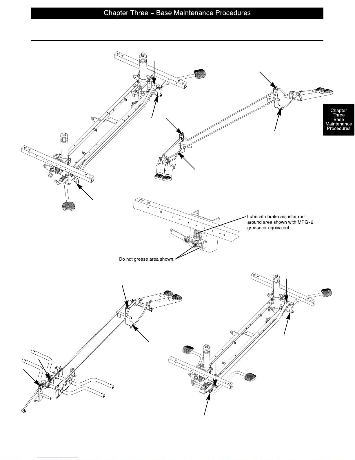
Base Lubrication 3–13. . . . . . . . . . . . . . . . . . . . . . . . . . . . . . . . . . . . . . . . . . . . . . . . . . . . . . . . . . . . . . . . . . . . . .
Page 3

LITTER MAINTENANCE
Siderail Latch Adjustment 4–2. . . . . . . . . . . . . . . . . . . . . . . . . . . . . . . . . . . . . . . . . . . . . . . . . . . . . . . . . . . . . . .
Arm Board Counterbalance Adjustment 4–2. . . . . . . . . . . . . . . . . . . . . . . . . . . . . . . . . . . . . . . . . . . . . . . . . . .
Pneumatic Fowler Adjustment 4–3. . . . . . . . . . . . . . . . . . . . . . . . . . . . . . . . . . . . . . . . . . . . . . . . . . . . . . . . . . .
Pneumatic Fowler Release Handle Adjustment 4–4. . . . . . . . . . . . . . . . . . . . . . . . . . . . . . . . . . . . . . . . . . . . .
Pneumatic Cylinder Replacement 4–5. . . . . . . . . . . . . . . . . . . . . . . . . . . . . . . . . . . . . . . . . . . . . . . . . . . . . . . .
Articulating Head Piece Adjustment 4–6. . . . . . . . . . . . . . . . . . . . . . . . . . . . . . . . . . . . . . . . . . . . . . . . . . . . . . .
QUICK REFERENCE REPLACEMENT PARTS LIST
Quick Reference Replacement Parts List 5–1, 5–2. . . . . . . . . . . . . . . . . . . . . . . . . . . . . . . . . . . . . . . . . . . . . .
ASSEMBLY DRAWINGS AND PARTS LISTS
Side Control Base Assembly 6–3 – 6–6. . . . . . . . . . . . . . . . . . . . . . . . . . . . . . . . . . . . . . . . . . . . . . . . . . . . . . .
End Control Base Assembly 6–7 – 6–10. . . . . . . . . . . . . . . . . . . . . . . . . . . . . . . . . . . . . . . . . . . . . . . . . . . . . .
Brake Adjuster Assembly 6–11. . . . . . . . . . . . . . . . . . . . . . . . . . . . . . . . . . . . . . . . . . . . . . . . . . . . . . . . . . . . . . .
Brake Cam Assembly 6–12. . . . . . . . . . . . . . . . . . . . . . . . . . . . . . . . . . . . . . . . . . . . . . . . . . . . . . . . . . . . . . . . . .
Side Control Pump Pedal Assembly 6–13. . . . . . . . . . . . . . . . . . . . . . . . . . . . . . . . . . . . . . . . . . . . . . . . . . . . .
Foot End Pump Pedal Assembly 6–14. . . . . . . . . . . . . . . . . . . . . . . . . . . . . . . . . . . . . . . . . . . . . . . . . . . . . . . .
Head End Pump Pedal Assembly 6–15. . . . . . . . . . . . . . . . . . . . . . . . . . . . . . . . . . . . . . . . . . . . . . . . . . . . . . .
Jack Assembly 6–16. . . . . . . . . . . . . . . . . . . . . . . . . . . . . . . . . . . . . . . . . . . . . . . . . . . . . . . . . . . . . . . . . . . . . . . .
Jack Base Assembly 6–17. . . . . . . . . . . . . . . . . . . . . . . . . . . . . . . . . . . . . . . . . . . . . . . . . . . . . . . . . . . . . . . . . .
Constant Flow Jack Assembly 6–18. . . . . . . . . . . . . . . . . . . . . . . . . . . . . . . . . . . . . . . . . . . . . . . . . . . . . . . . . .
Constant Flow Jack Base Assembly 6–19. . . . . . . . . . . . . . . . . . . . . . . . . . . . . . . . . . . . . . . . . . . . . . . . . . . . .
Jack Pump Piston Assembly 6–20. . . . . . . . . . . . . . . . . . . . . . . . . . . . . . . . . . . . . . . . . . . . . . . . . . . . . . . . . . . .
Base Assembly with Steerlock Caster Option 6–21. . . . . . . . . . . . . . . . . . . . . . . . . . . . . . . . . . . . . . . . . . . . .
Caster Assembly with Steerlock 6–22. . . . . . . . . . . . . . . . . . . . . . . . . . . . . . . . . . . . . . . . . . . . . . . . . . . . . . . . .
Standard Caster Assembly 6–23. . . . . . . . . . . . . . . . . . . . . . . . . . . . . . . . . . . . . . . . . . . . . . . . . . . . . . . . . . . . .
Base Assembly with Fifth Wheel Option 6–24. . . . . . . . . . . . . . . . . . . . . . . . . . . . . . . . . . . . . . . . . . . . . . . . . .
Pivot Rod Assembly 6–25. . . . . . . . . . . . . . . . . . . . . . . . . . . . . . . . . . . . . . . . . . . . . . . . . . . . . . . . . . . . . . . . . . .
Fifth Wheel Arm Assembly 6–26. . . . . . . . . . . . . . . . . . . . . . . . . . . . . . . . . . . . . . . . . . . . . . . . . . . . . . . . . . . . .
Optional Side Control Brake Assembly 6–28, 6–29. . . . . . . . . . . . . . . . . . . . . . . . . . . . . . . . . . . . . . . . . . . . .
Optional Uni–Lower Pedal Assembly 6–30. . . . . . . . . . . . . . . . . . . . . . . . . . . . . . . . . . . . . . . . . . . . . . . . . . . . .
Page 4

ASSEMBLY DRAWINGS AND PARTS LISTS (CONTINUED)
Optional Dual Lowering Pedal Assembly 6–31. . . . . . . . . . . . . . . . . . . . . . . . . . . . . . . . . . . . . . . . . . . . . . . . .
Base Labeling Assembly 6–32 – 6–34. . . . . . . . . . . . . . . . . . . . . . . . . . . . . . . . . . . . . . . . . . . . . . . . . . . . . . . .
Litter Assembly 6–35 – 6–37. . . . . . . . . . . . . . . . . . . . . . . . . . . . . . . . . . . . . . . . . . . . . . . . . . . . . . . . . . . . . . . .
Foot End Jack Support Assembly 6–38. . . . . . . . . . . . . . . . . . . . . . . . . . . . . . . . . . . . . . . . . . . . . . . . . . . . . . .
Head End Jack Support Assembly 6–39. . . . . . . . . . . . . . . . . . . . . . . . . . . . . . . . . . . . . . . . . . . . . . . . . . . . . . .
Zero Articulating Pneumatic Fowler Assembly 6–41– 6–45. . . . . . . . . . . . . . . . . . . . . . . . . . . . . . . . . . . . . . .
Single Articulating Pneumatic Fowler Assembly 6–46– 6–51. . . . . . . . . . . . . . . . . . . . . . . . . . . . . . . . . . . . .
Dual Articulating Pneumatic Fowler Assembly 6–52 – 6–57. . . . . . . . . . . . . . . . . . . . . . . . . . . . . . . . . . . . . .
Zero Articulating Crank Fowler Assembly 6–58, 6–59. . . . . . . . . . . . . . . . . . . . . . . . . . . . . . . . . . . . . . . . . . .
Single Articulating Crank Fowler Assembly 6–60 – 6–62. . . . . . . . . . . . . . . . . . . . . . . . . . . . . . . . . . . . . . . .
Dual Articulating Crank Fowler Assembly 6–64– 6–67. . . . . . . . . . . . . . . . . . . . . . . . . . . . . . . . . . . . . . . . . . .
Crank Fowler Assembly 6–68. . . . . . . . . . . . . . . . . . . . . . . . . . . . . . . . . . . . . . . . . . . . . . . . . . . . . . . . . . . . . . . .
Fowler Crankscrew Assembly 6–69. . . . . . . . . . . . . . . . . . . . . . . . . . . . . . . . . . . . . . . . . . . . . . . . . . . . . . . . . . .
Dual Articulating Head Piece Assembly 6–70 – 6–73. . . . . . . . . . . . . . . . . . . . . . . . . . . . . . . . . . . . . . . . . . .
Stationary Foot Section Assembly 6–74. . . . . . . . . . . . . . . . . . . . . . . . . . . . . . . . . . . . . . . . . . . . . . . . . . . . . . .
Knee Gatch Assembly 6–75. . . . . . . . . . . . . . . . . . . . . . . . . . . . . . . . . . . . . . . . . . . . . . . . . . . . . . . . . . . . . . . . .
Foot and Thigh Section Assembly 6–76. . . . . . . . . . . . . . . . . . . . . . . . . . . . . . . . . . . . . . . . . . . . . . . . . . . . . . .
Knee Gatch Crankscrew Assembly 6–77. . . . . . . . . . . . . . . . . . . . . . . . . . . . . . . . . . . . . . . . . . . . . . . . . . . . . .
Siderail to Litter Assembly, Two–Position Siderails 6–78. . . . . . . . . . . . . . . . . . . . . . . . . . . . . . . . . . . . . . . . .
Two–Position Siderail Assembly 6–79. . . . . . . . . . . . . . . . . . . . . . . . . . . . . . . . . . . . . . . . . . . . . . . . . . . . . . . . .
Siderail to Litter Assembly, Three–Position Siderails 6–80. . . . . . . . . . . . . . . . . . . . . . . . . . . . . . . . . . . . . . .
Three–Position Siderail Assembly 6–81. . . . . . . . . . . . . . . . . . . . . . . . . . . . . . . . . . . . . . . . . . . . . . . . . . . . . . .
Optional Transfer System Assembly 6–82. . . . . . . . . . . . . . . . . . . . . . . . . . . . . . . . . . . . . . . . . . . . . . . . . . . . .
Optional Transfer Board Assembly, Left 6–83. . . . . . . . . . . . . . . . . . . . . . . . . . . . . . . . . . . . . . . . . . . . . . . . . .
Optional Transfer Board Assembly, Right 6–84. . . . . . . . . . . . . . . . . . . . . . . . . . . . . . . . . . . . . . . . . . . . . . . . .
Optional Transfer Board Support Assembly 6–85. . . . . . . . . . . . . . . . . . . . . . . . . . . . . . . . . . . . . . . . . . . . . . .
Optional Pre–Op Post–Op Head Piece Mounting Assembly, Crank Fowler 6–86, 6–87. . . . . . . . . . . . . .
Optional Pre–Op Post–Op Head Piece Assembly, Crank Fowler 6–88, 6–89. . . . . . . . . . . . . . . . . . . . . . .
Page 5

ASSEMBLY DRAWINGS AND PARTS LISTS (CONTINUED)
Standard, Removable I.V. Pole Assembly 6–90. . . . . . . . . . . . . . . . . . . . . . . . . . . . . . . . . . . . . . . . . . . . . . . . .
Optional 2–Stage I.V. Pole Assembly 6–91, 6–92. . . . . . . . . . . . . . . . . . . . . . . . . . . . . . . . . . . . . . . . . . . . . .
Optional 3–Stage I.V. Pole Assembly 6–93–6–95. . . . . . . . . . . . . . . . . . . . . . . . . . . . . . . . . . . . . . . . . . . . . .
Optional I.V. Pole Latch Assembly 6–96. . . . . . . . . . . . . . . . . . . . . . . . . . . . . . . . . . . . . . . . . . . . . . . . . . . . . . .
Optional Foot Board/Chartholder Assembly 6–97. . . . . . . . . . . . . . . . . . . . . . . . . . . . . . . . . . . . . . . . . . . . . . .
Optional Upright Oxygen Bottle Holder Assembly 6–97. . . . . . . . . . . . . . . . . . . . . . . . . . . . . . . . . . . . . . . . . .
Optional Foot Board Extension/Defibrillator Tray Assembly 6–98. . . . . . . . . . . . . . . . . . . . . . . . . . . . . . . . . .
Optional Wrist Rest Assembly 6–99, 6–100. . . . . . . . . . . . . . . . . . . . . . . . . . . . . . . . . . . . . . . . . . . . . . . . . . . .
Optional Drape Support Assembly 6–101. . . . . . . . . . . . . . . . . . . . . . . . . . . . . . . . . . . . . . . . . . . . . . . . . . . . . .
Optional Accessory Rail Assembly 6–102. . . . . . . . . . . . . . . . . . . . . . . . . . . . . . . . . . . . . . . . . . . . . . . . . . . . . .
Optional Arm Board Assembly 6–103, 6–104. . . . . . . . . . . . . . . . . . . . . . . . . . . . . . . . . . . . . . . . . . . . . . . . . .
F–Size O2 Bottle Retainer Assembly 6–105. . . . . . . . . . . . . . . . . . . . . . . . . . . . . . . . . . . . . . . . . . . . . . . . . . . .
Mattresses and Siderail Pads 6–106. . . . . . . . . . . . . . . . . . . . . . . . . . . . . . . . . . . . . . . . . . . . . . . . . . . . . . . . . .
Page 6
This quick reference guide will help you locate the section of the manual you need to service your
equipment or to order parts for it.
Find the black tab matching the section you are looking for and match it with the corresponding
tabs that mark the section in the body of the manual.
Refer to the main table of contents at the front of the manual or each sectional table of contents
to locate specific topics.
Page 7

Page 8
INTRODUCTION
This manual is designed to assist you with the maintenance of the 1069 Head/Neck Surgery Bed. Read it
thoroughly before beginning any maintenance on the equipment.
SPECIFICATIONS
Maximum Weight Capacity 500 pounds
Overall Bed Length/Width 88”/31.5”
Minimum/Maximum Bed Height 22.5”/36”
Fowler Angle 0 to 90
Knee Gatch Angle 0 to 35
Trendelenburg/Reverse Trendelenburg –18 to +18
Stryker reserves the right to change specifications without notice.
WARNING / CAUTION / NOTE DEFINITION
The words WARNING, CAUTION and NOTE carry special meanings and should be carefully reviewed.
WARNING
The personal safety of the patient or user may be involved. Disregarding this information could result in injury
to the patient or user.
CAUTION
These instructions point out special procedures or precautions that must be followed to avoid damaging the
equipment.
NOTE
This provides special information to make maintenance easier or important instructions clearer.
WARNING
Patients should be discouraged from sitting directly on the ends of the stretcher. Excessive weight will cause
the litter surface to tip up, possibly causing patient injury.
Always apply the caster brakes when a patient is getting on or off the stretcher. Push on the stretcher to ensure the brakes are securely locked. Always engage the brakes unless the stretcher is being moved. Injury
could result if the stretcher moves while a patient is getting on or off the stretcher.
page 1–1
Page 9

Warranty
Limited Warranty:
Stryker Medical Division, a division of Stryker Corporation, warrants to the original purchaser that its products
should be free from defects in material and workmanship for a period of one (1) year after date of delivery.
Stryker’s obligation under this warranty is expressly limited to supplying replacement parts and labor for, or
replacing, at its option, any product which is, in the sole discretion of Stryker, found to be defective. Stryker
warrants to the original purchaser that the frame and welds on its beds will be free from structural defects
for as long as the original purchaser owns the bed. If requested by Stryker, products or parts for which a
warranty claim is made shall be returned prepaid to Stryker’s factory. Any improper use or any alteration or
repair by others in such manner as in Stryker’s judgement affects the product materially and adversely shall
void this warranty. Any repair of Stryker products using parts not provided or authorized by Stryker shall void
this warranty. No employee or representative of Stryker is authorized to change this warranty in any way.
Stryker Medical stretchers are designed for a 10 year expected life under normal use conditions and appropriate periodic maintenance as described in the maintenance manual for each device.
This statement constitutes Stryker’s entire warranty with respect to the aforesaid equipment. STRYKER
MAKES NO OTHER WARRANTY OR REPRESENTATION, EITHER EXPRESSED OR IMPLIED, EXCEPT
AS SET FORTH HEREIN. THERE IS NO WARRANTY OF MERCHANTABILITY AND THERE ARE NO
WARRANTIES OF FITNESS FOR ANY PARTICULAR PURPOSE. IN NO EVENT SHALL STRYKER BE
LIABLE HEREUNDER FOR INCIDENTAL OR CONSEQUENTIAL DAMAGES ARISING FROM OR IN ANY
MANNER RELATED TO SALES OR USE OF ANY SUCH EQUIPMENT.
To Obtain Parts and Service:
Stryker products are supported by a nationwide network of dedicated Stryker Field Service Representatives.
These representatives are factory trained, available locally, and carry a substantial spare parts inventory to
minimize repair time. Simply call your local representative, or call Stryker Customer Service at (800)
327–0770.
Service Contract Coverage:
Stryker has developed a comprehensive program of service contract options designed to keep your equipment operating at peak performance at the same time it eliminates unexpected costs. We recommend that
these programs be activated before the expiration of the new product warranty to eliminate the potential of
additional equipment upgrade charges.
A SERVICE CONTRACT HELPS TO:
Ensure equipment reliability
Stabilize maintenance budgets
Diminish downtime
Establish documentation for JCAHO
Increase product life
Enhance trade–in value
Address risk management and safety
page 1–2
Page 10
Warranty
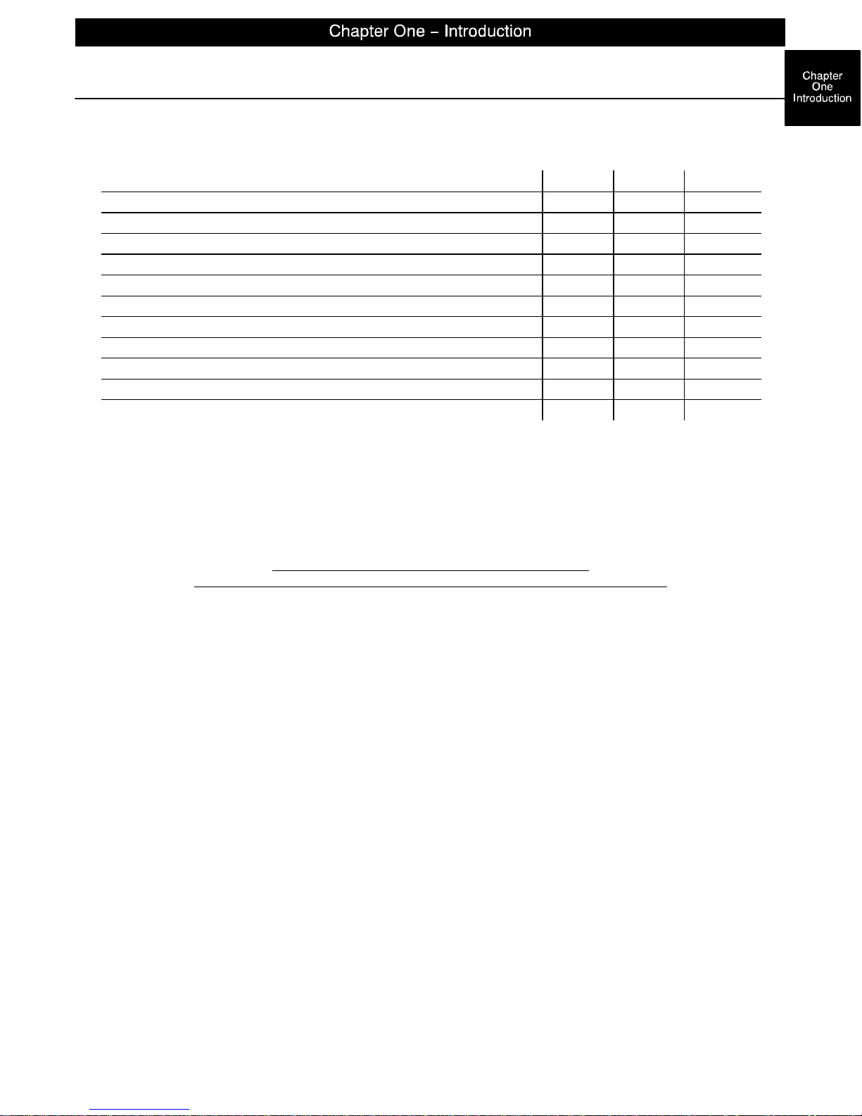
Stryker offers the following service contract programs:
SPECIFICATIONS GOLD SILVER PM* ONLY
Annually scheduled preventative maintenance X X
All parts,** labor, and travel X X
Unlimited emergency service calls X X
Priority one contact; two hour phone response X X X
Most repairs will be completed within 3 business days X X
JCAHO documentation X X X
On–site log book w/ preventative maintenance & emergency service records X
Factory–trained Stryker Service Technicians X X X
Stryker authorized parts X X X
End of year summary X
Stryker will perform all service during regular business hours (9–5) X X X
* Replacement parts and labor for products under PM contract will be discounted.
** Does not include any disposable items, I.V. poles (except for Stryker HD permanent poles), mattresses, or damage re-
sulting from abuse.
Stryker Medical also offers personalized service contracts.
Pricing is determined by age, location, model and condition of product.
For more information on our service contracts,
please call your local representative or call (800) 327–0770 (option #2).
Return Authorization:
Merchandise cannot be returned without approval from the Stryker Customer Service Department. An authorization number will be provided which must be printed on the returned merchandise. Stryker reserves the
right to charge shipping and restocking fees on returned items.
SPECIAL, MODIFIED, OR DISCONTINUED ITEMS NOT SUBJECT TO RETURN.
Damaged Merchandise:
ICC Regulations require that claims for damaged merchandise must be made with the carrier within fifteen
(15) days of receipt of merchandise. DO NOT ACCEPT DAMAGED SHIPMENTS UNLESS SUCH DAMAGE
IS NOTED ON THE DELIVERY RECEIPT AT THE TIME OF RECEIPT. Upon prompt notification, Stryker
will file a freight claim with the appropriate carrier for damages incurred. Claim will be limited in amount to
the actual replacement cost. In the event that this information is not received by Stryker within the fifteen
(15) day period following the delivery of the merchandise, or the damage was not noted on the delivery receipt
at the time of receipt, the customer will be responsible for payment of the original invoice in full.
Claims for any short shipment must be made within thirty (30) days of invoice.
International Warranty Clause:
This warranty reflects U.S. domestic policy. Warranty outside the U.S. may vary by country. Please contact
your local Stryker Medical representative for additional information.
page 1–3
Page 11

Page 12

GENERAL INFORMATION
This section contains cleaning instructions and a checklist to assist with the routine preventive maintenance
and cleaning of your equipment.
In the text, the words “right” and “left” refer to the right and left sides of a patient lying face up on the bed.
PREVENTIVE MAINTENANCE CONTENTS
Cleaning 2–2. . . . . . . . . . . . . . . . . . . . . . . . . . . . . . . . . . . . . . . . . . . . . . . . . . . . . . . . . . . . . . . . . . . . . . . . . . . . . .
Preventive Maintenance Checklist 2–3. . . . . . . . . . . . . . . . . . . . . . . . . . . . . . . . . . . . . . . . . . . . . . . . . . . . . . . .
page 2–1
Page 13
Cleaning
Hand wash all surfaces of the bed with warm water and mild detergent. Dry thoroughly. DO NOT STEAM
CLEAN, PRESSURE WASH, HOSE OFF OR ULTRASONICALLY CLEAN. Using these methods of cleaning
is not recommended and may void this product’s warranty.
Clean Velcro AFTER EACH USE. Saturate Velcro with disinfectant and allow disinfectant to evaporate. (Appropriate disinfectant for nylon Velcro should be determined by the hospital.)
In general, when used in those concentrations recommended by the manufacturer, either phenolic type or
quaternary type disinfectants can be used with Staph–Chek fabrics. Iodophor type disinfectants are not recommended for use on Staph–Chek fabrics because staining may result. The following products have been
tested by the Herculite Laboratory and have been found not to have a harmful effect on Staph–Chek fabrics
WHEN USED IN ACCORDANCE WITH MANUFACTURERS RECOMMENDED DILUTION.*
TRADE NAME
A33 Quaternary Airwick (Professional Products Division) 2 ounces/gallon
A33 (dry) Quaternary Airwick (Professional Products Division) 1/2 ounce/gallon
Beaucoup Phenolic Huntington Laboratories 1 ounce/gallon
Blue Chip Quaternary S.C. Johnson 2 ounces/gallon
Elimstaph Quaternary Walter G. Legge 1 ounce/gallon
Franklin Phe-
nomysan F2500
Franklin Sentinel Quaternary Purex Corporation 2 ounces/gallon
Galahad Phenolic Puritan Churchill Chemical Company 1 ounce/gallon
Hi–Tor Quaternary Huntington Laboratories 1/2 ounce/gallon
LPH Phenolic Vestal Laboratories 1/2 ounce/gallon
Matar Phenolic Huntington Laboratories 1/2 ounce/gallon
Omega Quaternary Airwick (Professional Products Division) 1/2 ounce/gallon
Quanto Quaternary Huntington Laboratories 1 ounce/gallon
Sanikleen Quaternary West Chemical Products 2 ounces/ gallon
Sanimaster II Quaternary Service Master 1 ounce/gallon
Vesphene Phenolic Vestal Laboratories 1 1/4 ounce/ gallon
DISINFECTANT
Phenolic Purex Corporation 1 1/4 ounce/gallon
TYPE
MANUFACTURER
*MANUFACTURER’S
RECOMMENDED
DILUTION
Quaternary Germicidal Disinfectants, used as directed, and/or Chlorine Bleach products, typically 5.25% So dium Hypochlorite in dilutions ranging between 1 part bleach to 100 parts water, and 2 parts bleach
to 100 parts water are not considered mild detergents. These products are corrosive in nature and
may cause damage to your stretcher if used improperly. If these types of products are used to clean
Stryker patient handling equipment, measures must be taken to insure the stretchers are rinsed with clean
water and thoroughly dried following cleaning. Failure to properly rinse and dry the stretchers will leave a corrosive residue on the surface of the stretcher, possibly causing premature corrosion of critical components.
NOTE
Failure to follow the above directions when using these types of cleaners may void this product’s warranty.
REMOVAL OF IODINE COMPOUNDS
This solution may be used to remove iodine stains from mattress cover and foam footrest pad surfaces.
1. Use a solution of 1–2 tablespoons Sodium Thiosulfate in a pint of warm water to clean the stained area.
Clean as soon as possible after staining occurs. If stains are not immediately removed, allow solution to
soak or stand on the surface.
2. Rinse surfaces which have been exposed to the solution in clear water before returning bed to service.
page 2–2
Page 14
Preventive Maintenance Checklist
CHECKLIST
All fasteners secure (reference all assembly prints)
Siderails move and latch properly (page 4–2)
Engage brake pedal and push on the stretcher to ensure all casters lock securely (page 3–5)
Steer function working properly
All casters secure and swiveling properly
Body restraints working properly
I.V. pole intact and operating properly (page 6–90 – page 6–95)
Oxygen bottle holder intact and operating properly
Fowler operating properly (pneumatic – page 4–3)
Optional articulating head piece locking and releasing properly (page 4–6) – check immediately if the
head piece is bumped on a door, wall or other obstacle while the stretcher is being moved
Knee Gatch operating properly
Trendelenberg/Reverse Trendelenberg operating properly
No rips or cracks in mattress cover
Arm boards intact and operating properly (page 4–2)
Arm board support levers intact and operating properly (page 6–85)
Ground chain intact
No leaks at hydraulic connections
Hydraulic jacks holding properly (page 3–8)
Hydraulic drop rate set properly (page 3–9)
Hydraulic oil level sufficient (page 3–9)
Lubricate where required, including the brake adjuster assembly and brake cam (page 3–13)
Serial No.
Completed By:_________________________________ Date:_____________
NOTE
Preventative maintenance should be performed at a minimum of annually. A preventative maintenance program should be established for all Stryker Medical equipment. Preventative maintenance may need to be
performed more frequently based on the usage level of the product.
NOTE
References to the right or left side of the stretcher refer to the right and left sides of a patient
lying face up on the stretcher.
page 2–3
Page 15

Page 16

GENERAL INFORMATION
This section contains tool lists and step–by–step procedures to assist with the maintenance and servicing
of the base portion of your equipment.
In the text, the words “right” and “left” refer to the right and left sides of a patient lying face up on the bed.
BASE MAINTENANCE CONTENTS
Caster Assembly Replacement 3–2. . . . . . . . . . . . . . . . . . . . . . . . . . . . . . . . . . . . . . . . . . . . . . . . . . . . . . . . . . .
Fifth Wheel Replacement 3–2. . . . . . . . . . . . . . . . . . . . . . . . . . . . . . . . . . . . . . . . . . . . . . . . . . . . . . . . . . . . . . . .
Caster Cover Installation and Removal 3–3. . . . . . . . . . . . . . . . . . . . . . . . . . . . . . . . . . . . . . . . . . . . . . . . . . . .
Brake Cam Replacement 3–4. . . . . . . . . . . . . . . . . . . . . . . . . . . . . . . . . . . . . . . . . . . . . . . . . . . . . . . . . . . . . . . .
Brake Ring Replacement 3–4. . . . . . . . . . . . . . . . . . . . . . . . . . . . . . . . . . . . . . . . . . . . . . . . . . . . . . . . . . . . . . . .
Brake Adjustment 3–5. . . . . . . . . . . . . . . . . . . . . . . . . . . . . . . . . . . . . . . . . . . . . . . . . . . . . . . . . . . . . . . . . . . . . .
Base Side Control Pedal Linkage Adjustment 3–5. . . . . . . . . . . . . . . . . . . . . . . . . . . . . . . . . . . . . . . . . . . . . .
Base Side Control Brake/Steer Gear Replacement 3–6. . . . . . . . . . . . . . . . . . . . . . . . . . . . . . . . . . . . . . . . . .
Uni–Pedal Replacement 3–6. . . . . . . . . . . . . . . . . . . . . . . . . . . . . . . . . . . . . . . . . . . . . . . . . . . . . . . . . . . . . . . . .
Jack Replacement 3–7. . . . . . . . . . . . . . . . . . . . . . . . . . . . . . . . . . . . . . . . . . . . . . . . . . . . . . . . . . . . . . . . . . . . . .
Jack Assembly Torque Specification 3–8. . . . . . . . . . . . . . . . . . . . . . . . . . . . . . . . . . . . . . . . . . . . . . . . . . . . . .
Hydraulic Troubleshooting 3–8. . . . . . . . . . . . . . . . . . . . . . . . . . . . . . . . . . . . . . . . . . . . . . . . . . . . . . . . . . . . . . .
Removing Excess Air (Vacuum) from the Hydraulic System 3–8. . . . . . . . . . . . . . . . . . . . . . . . . . . . . . . . . .
Checking Hydraulic Fluid Level 3–9. . . . . . . . . . . . . . . . . . . . . . . . . . . . . . . . . . . . . . . . . . . . . . . . . . . . . . . . . . .
Jack Descent Rate Adjustment 3–9. . . . . . . . . . . . . . . . . . . . . . . . . . . . . . . . . . . . . . . . . . . . . . . . . . . . . . . . . . .
Constant Flow Jack Descent Rate Adjustment 3–10. . . . . . . . . . . . . . . . . . . . . . . . . . . . . . . . . . . . . . . . . . . .
Adjustable Pressure Compensated (P.C.) Valve Replacement 3–10. . . . . . . . . . . . . . . . . . . . . . . . . . . . . . .
Hydraulic Jack Valve Replacement 3–11, 3–12. . . . . . . . . . . . . . . . . . . . . . . . . . . . . . . . . . . . . . . . . . . . . . . .
Base Lubrication 3–13. . . . . . . . . . . . . . . . . . . . . . . . . . . . . . . . . . . . . . . . . . . . . . . . . . . . . . . . . . . . . . . . . . . . . .
page 3–1
Page 17
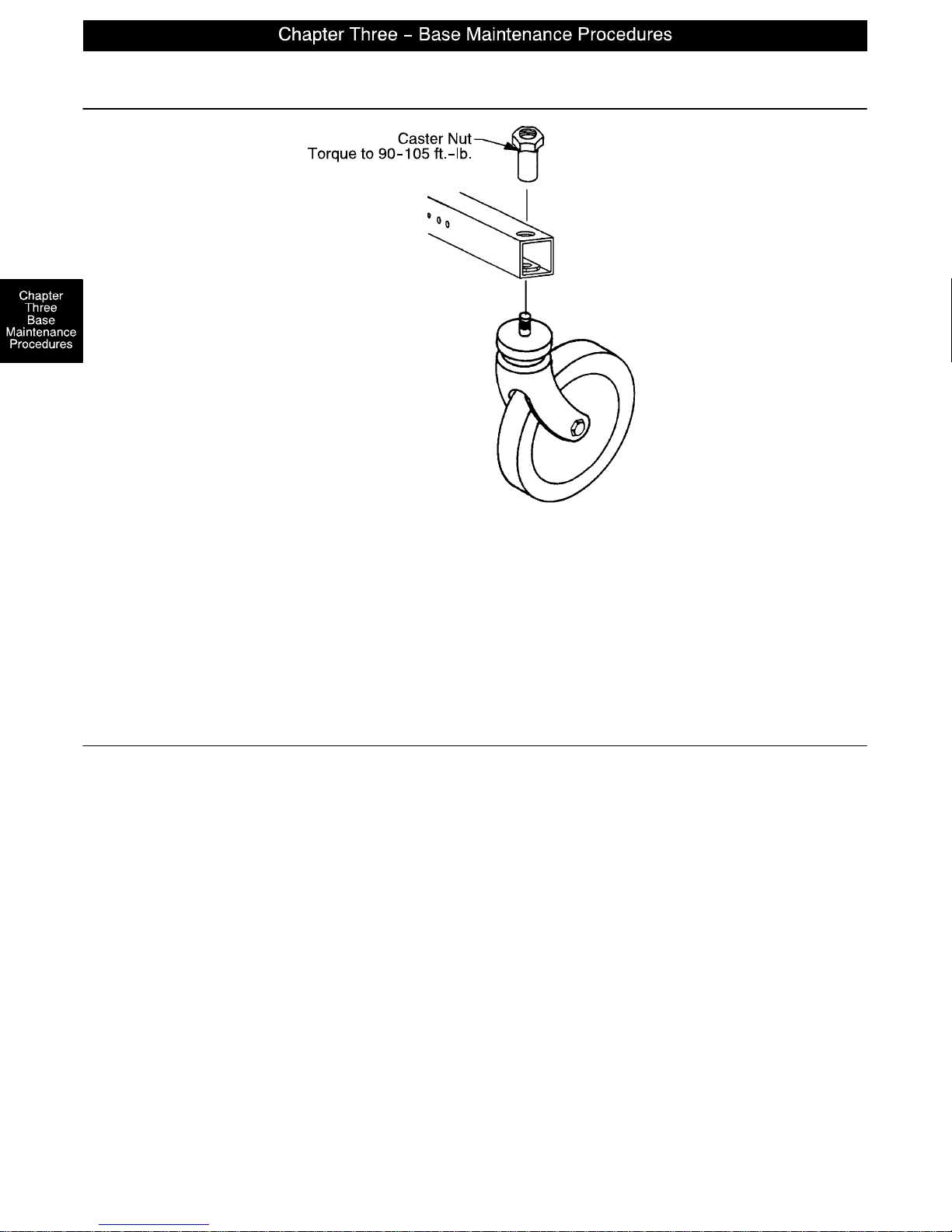
Caster Assembly Replacement
1. Remove the old caster assembly.
2. Install the replacement caster and caster nut. T ighten the caster nut to 90–105 ft.–lb. with a torque wrench.
NOTE
A new caster assembly with a 3M patch does not require the application of Loctite at assembly. However,
the patch is appropriate for only one installation. If the caster is removed and reassembled for any reason,
apply Loctite 242 to two or three threads of both the bolt and caster nut and tighten to 90–105 ft.–lb. with a
torque wrench.
Fifth Wheel Replacement
Required Tools:
Pliers String or Bungee Cord 3/16” Allen Wrench
(2) 9/16” Box End Wrenches
Procedure:
1. Apply the stretcher brakes.
2. Pump the litter up to full height.
3. Lift and support the base hood using string or bungee cord.
4. Using pliers, remove the cotter pin from the end of the fifth wheel pivot rod and remove the two washers.
5. Pull up on the fifth wheel arm and pull down on the tension spring to release the pressure on the arm.
6. Using a 3/16” Allen wrench, remove the hex Allen bolt from the center of the pivot rod and pull the pivot
rod out of the wheel arm.
7. Reverse the above steps to install a new fifth wheel assembly.
NOTE
To replace the wheel only, use two 9/16” box end wrenches to remove the bolt and nut holding it to the wheel
arm.
page 3–2
Page 18
1.
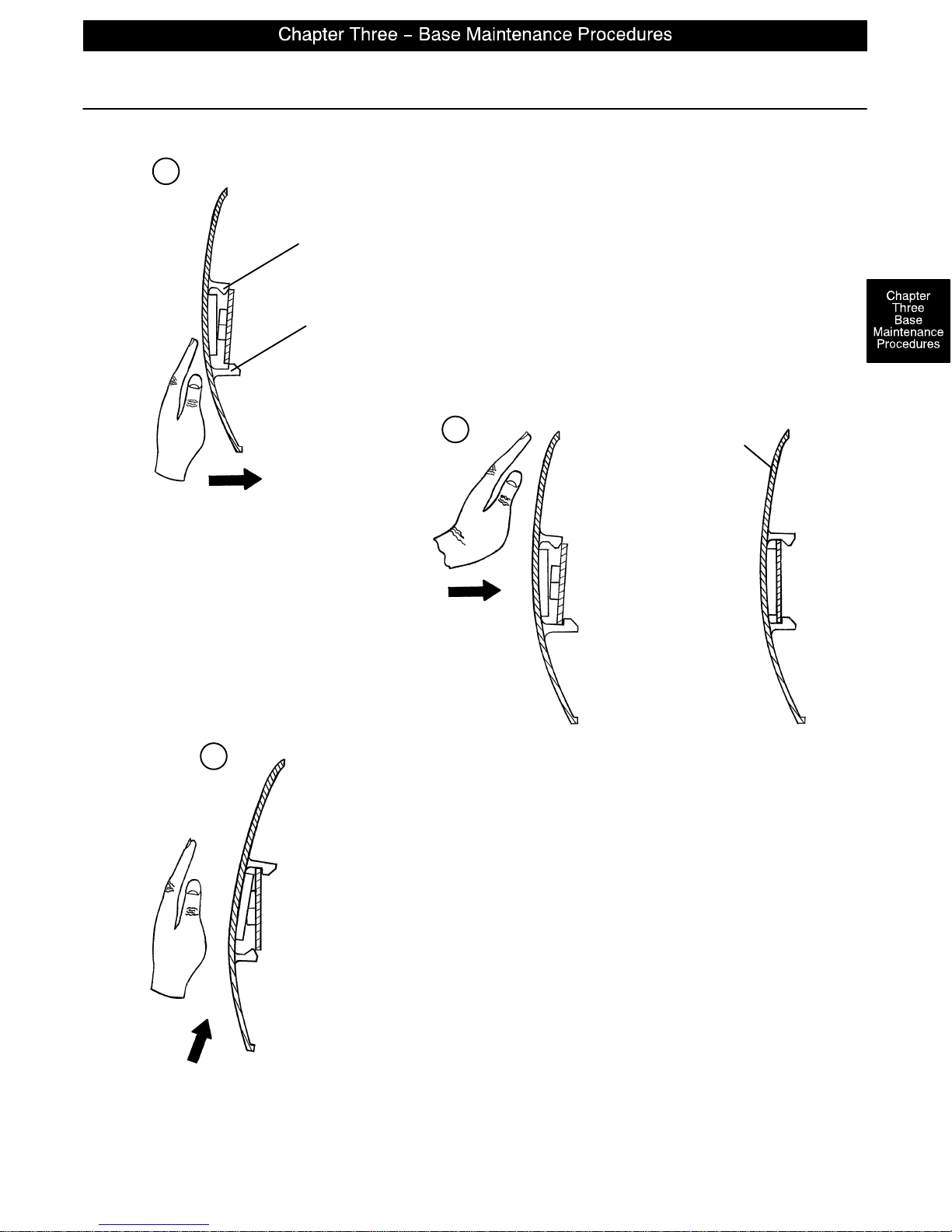
Caster Cover Installation and Removal
Looking through the larger of the two side cut–outs,
Double Prongs
Single Prong
align cover with axle nut or bolt head, as shown.
Push down on the opposite side of the cover until
single prong engages with caster horn.
Top View (Cut–Away)
Push with palm on cover until
double prongs engage.
3.
To remove wheel cover, insert large screwdriver into cut–out in
side of wheel cover and into the space between the double prongs.
Pry up cover to disengage double prongs and push sharply upward
to disengage single prong.
2.
Properly Attached
Cover
Top View (Cut–Away)
Top View (Cut–Away)
page 3–3
Page 19
Brake Cam Replacement
Brake Cam Part Number 715–201–213
Required Tools:
Phillips Screwdriver String or Bungee Cord 3/32” Allen Wrench
1/8” Allen Wrench
Procedure:
1. Remove the four Phillips screws holding the base hood to the frame. Lift and support the base hood using
string or bungee cord.
2. Using a 3/32” Allen wrench, loosen the set screw holding the brake adjuster to the brake ring and turn the
adjuster clockwise to remove it.
3. Using a 1/8 ” Allen wrench, remove the shoulder bolt and nut holding the brake link on the cam and remove
the cam.
4. Reverse steps 3 and 4 to install the new cam. Verify the brakes are operating properly. If adjustment is
required, see page 3–5. Reinstall the base hood.
Brake Ring Replacement
Brake Ring Part Number 715–1–61
Required Tools:
Phillips Screwdriver String or Bungee Cord Floor Jack, Small Crate (or equivalent)
Large Standard Screwdriver 3/32” Allen Wrench 11/16” Socket & Ratchet
5/8” Wrench Needle–Nose Pliers (2) 7/16” Wrenches
Procedure:
1. Remove the four Phillips screws holding the base hood to the frame. Lift and support the base hood using
string or bungee cord. Put the brake/steer pedal in the neutral position. Lift the end of the base needing
service until the casters are approximately 12” off the floor and support it with a jack or the equivalent.
2. Using a 3/32” Allen wrench, loosen the set screw holding the brake adjuster to the brake ring and turn the
adjuster clockwise to remove it.
3. Remove the caster covers on both casters (see page 3–3).
4. Remove one of the casters (see page 3–2). On the other caster, use an 11/16” socket and ratchet
and a 5/8” wrench to remove the nut and bolt holding the wheel on the caster horn and remove only the
wheel.
5. Using needle–nose pliers, carefully squeeze and remove the spring between the brake cam and the brake
ring.
WARNING
The spring is tightly compressed. Use caution when removing it or personal injury could result.
6. If you are working on an end control base, remove the spring from the pump pedal.
7. Lower the brake ring and remove it from the base. Remove the brake pads and bushings and install them
on the new brake ring.
8. Reverse the above steps to install the new brake ring and reinstall the caster and wheel. Apply and release
the brakes to verify they operate properly. If adjustment is required, see page 3–5. Reinstall the base
hood.
page 3–4
Page 20
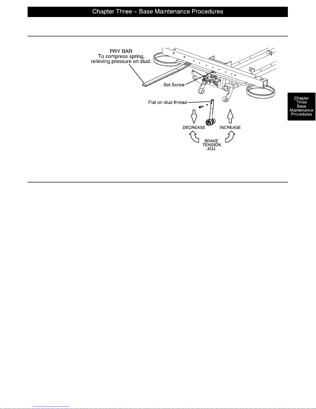
Required Tools:
3/32” Hex Allen Wrench
Pry Bar
Thread ”Locktite”
Base Side Control Pedal Linkage Adjustment
Brake Adjustment
Flat on thread of stud must always be
aligned with the set screw. Turn must
always be full circle only.
Required Tools:
3/8” Wrench 5/32” Hex Allen Wrench 7/16” Wrench
Bungee Cords
Adjustment Procedure:
1. Place 150–200 pounds on the litter and pump the litter up to full height.
2. Lift the base hood, separating the hood from the base frame. Using the bungee cords, support the base
hood.
3. Using a 3/8” wrench and a 5/32” hex Allen wrench, loosen the appropriate pedal linkage adjustment nut
until the jack stops ”drifting”. Raise the litter to full up.
4. Tighten the pedal linkage adjustment nut until the jack begins to slowly descend.
5. Using a 7/16” wrench, back the pedal linkage adjustment nut out four full turns. Raise the litter to full up.
6. Loosen the pedal linkage adjustment nut and ensure no drift occurs. If the jack drifts, repeat procedure.
page 3–5
Page 21
Base Side Control Brake/Steer Gear Replacement
Required Tools:
Pliers String or Bungee Cord Floor Jack or Equivalent
1/8” Allen Wrench 5/32” Allen Wrench 3/8” Box End Wrench
(2) 9/16” Box End Wrenches 3/16” Punch 1/4” Punch
Hammer
Procedure:
1. Apply the stretcher brakes.
2. Pump the litter up to full height.
3. Lift and support the base hood using string or bungee cord.
4. Using pliers, remove the cotter pins from both jack pump pistons and the pump linkage.
5. Using the 9/16” box end wrenches, remove the two bearing plate bolts.
6. Remove the cotter pin on the side brake bar.
7. Remove the bearing plate and pull out the idler gear rod while holding onto the gear. Lift the gear out.
8. Slide the miter gear away from the rod spacer and remove the dowel pin.
9. Using the floor jack, raise the side of the base you are working on approximately four inches.
10. Rotate the brake bar so the pedals are upside down.
11. Using a 1/4” punch and a hammer, remove the groove pin from the side brake rod.
12. Using a 3/16” punch and hammer, remove the 3/16” groove pin from the pedal.
13. Using a 5/32” Allen wrench, remove the set screw from the collar inside the gear box.
14. Remove the brake rod while holding the gear on the rod.
15. Using a 1/8” Allen wrench and a 3/8” box end wrench, remove the nuts and bolts holding the brake link
to the rod.
16. Using a 5/32” Allen wrench, remove the set screw from the collar outside of the gear box.
17. Using a 1/4” punch, remove the roll pin from the cam and brake link collar.
18. Reverse the above steps to install the replacement gear.
19. Inspect each gear for wear. Lube with MPG–2 grease or the equivalent if necessary.
Uni–Pedal Replacement
Required Tools:
Drill w/3/16” Drill Bit Floor Jack Pop Rivet Tool
Replacement Procedure:
1. Set the stretcher brake and pump the litter up fully.
2. Use the floor jack to raise the side of the base frame off the floor approximately four inches.
3. Using a drill with a 3/16” drill bit, drill out the rivets on the bottom of the pedal to be replaced.
4. Using a pop rivet tool and rivets, install the replacement pedal.
5. Lower the stretcher to the floor. Test the operation of the pedal before returning the stretcher to service.
page 3–6
Page 22
Jack Replacement (Without Compression Spring)
Required Tools:
3/8” Wrench 1/2” Socket 1/2” Wrench
Needle–Nosed Pliers
Replacement Procedure:
1. Apply stretcher brakes. Raise litter to full up. Raise Fowler to full up and raise siderails.
2. Use a 3/8” wrench to remove the bolt in the litter support tube above black bellows on both ends.
3. With the assistance of another person, lift off the stretcher litter and set it aside, taking care not to damage
the siderails, etc.
4. Push down on the jack actuator to put the jack in the full down position.
5. Lift off the plastic base hood, separating the Velcro holding it to the base frame.
6. Using a 1/2” socket and 1/2” wrench, remove the four bolts, washers and nuts holding the jack support
straps to the base frame.
7. Using needle–nosed pliers, remove the two cotter keys on the pump link and remove the pump link.
8. Using a 1/ 2 ” socket and a 1/2” wrench, remove the four bolts holding the jack base to the base frame (using
a 3” extension may be required). Remove the jack from the base frame.
9. Reverse steps 6–8 to install the replacement jack. Reinstall the base hood and the stretcher litter.
Jack Replacement (With Compression Spring)
Required Tools:
3/8” Wrench Needle–Nosed Pliers Straight Screwdriver
Spring Compression Tool (Part Number 1210–1–3)
Replacement Procedure:
1. Apply stretcher brakes. Raise litter to full up. Raise Fowler to full up and raise siderails.
2. Use a 3/8” wrench to remove the bolt in the litter support tube above black bellows on both ends.
3. With the assistance of another person, lift off the stretcher litter and set it aside, taking care not to damage
the siderails, etc.
4. Push down on the jack actuator to put the jack in the full down position.
5. Lift off the plastic base hood, separating the Velcro holding it to the base frame.
6. Using needle–nosed pliers, pull cotter pin from pump cylinder.
7. Using a straight screwdriver and pump spring compression tool (available upon request), compress the
pump spring and pry the pump link out of the pump cylinder.
CAUTION
Be sure not to let the pump piston come out of the jack or damage to the unit may occur.
8. Remove and replace jack as described in the procedure above.
9. Replace pump spring and pump link using the straight screwdriver and the pump compression tool.
10. Reinstall the base hood and the stretcher litter.
page 3–7
Page 23
Jack Assembly Torque Specification
Jack Assembly with Threads Oiled
1. Jack Cap Assembly to Jack Actuator Cylinder 75 to 85 Foot Pounds
2. Jack Actuator Cylinder to Jack Base Assembly 55 to 65 Foot Pounds
Jack Base Assembly with Threads Oiled
1. Jack Pump Cylinder to Jack Base Machined 45 to 55 Foot Pounds
2. Jack Pin Housing to Jack Base Machined 35 to 45 Foot Pounds
3. Jack Base Plugs to Jack Base Machined 8 to 12 Foot Pounds
4. Jack Valve Plug to Jack Base Machined 8 to 12 Foot Pounds
5. Flow Control Valve to Jack Base Machined 16 to 20 Foot Pounds
Hydraulic Troubleshooting
Be sure the pedal linkage has been adjusted properly before beginning service on the jacks (see page 3–5).
PROBLEM/SYMPTOM SOLUTION
Jack will not raise to full height. Add hydraulic fluid (page 3–9). Check for leaks.
Jack will not hold in raised position. Close the needle valve completely. If the jack holds,
replace the release valve (page 3–12).
Jack will not pump up and the jack actuator
rod does not move.
Jack will not pump up but the jack actuator rod
Close the needle valve. If the jack will now pump up,
replace the release valve (page 3–12). If the jack still
will not pump up after closing the needle valve, replace
the poppet valve (page 3–12).
Replace the check valve (page 3–11).
does move when the pump pedal is activated.
Jack will not pump up and the jack actuator
rod may or may not move.
Contact Stryker technical service at 1–800–327–0770 for further assistance.
Remove the excess air (vacuum) in the hydraulic system (see below).
Removing Excess Air (Vacuum) from the Hydraulic System
Procedure:
1. Verify all hydraulic linkages are secure and operating properly (see page 3–5).
2. Using pump pedal, actuate system several times. This will force the air through the system and the jack
should now pump up.
page 3–8
Page 24
Checking Hydraulic Fluid Level
Required Tools:
3/8 Open End Wrench 3/4 Open End Wrench
Procedure:
WARNING
To avoid personal injury or damage to the stretcher, remove the litter and the base hood before beginning
service on the jacks.
1. Using a 3/8 open end wrench, remove square head set screws from both head and foot end jack support
tubes. Remove litter top and set aside.
2. Lift base hood off base frame and set aside.
3. Verify there are no hydraulic leaks. If there are, jack replacement will be necessary.
4. Lower the jack to the full down position.
5. Using a 3/4 open end wrench, slowly turn the fill plug located on the side of the reservoir counterclockwise
to allow excess system pressure to vent. Remove the fill plug.
6. The hydraulic fluid should be visible at the bottom of the fill hole. If it is not, add Mobil Aero HFA hydraulic
fluid (Stryker part number 2020–70–475) until the fluid is visible at the bottom of the fill hole. Replace the
fill plug.
CAUTION
Use of other types of oil may damage hydraulic units.
7. Replace the hood and the litter.
Jack Descent Rate Adjustment
Required Tools:
Screwdriver Bungee Cords (or equivalent)
Adjustment Procedure:
1. Pump the litter up to full height.
2. Lift the base hood, separating the hood from the base frame. Using the bungee cords, support the base
hood.
3. The descent rate needle valve is located on the base of the jack. Turning the needle valve clockwise, with
a screwdriver, will decrease the rate of descent. Turning it counterclockwise will increase the rate of descent.
4. Adjust the needle valve so that the foot end of the stretcher descends slightly faster than the head end.
NOTE
The larger percentage of a patient’s weight is located in the torso area. Adjust descent rate accordingly.
5. Remove the bungee cords supporting the base hood and secure the hood to the base frame.
NOTE
The jack descent rate was preset at the factory to drop the foot end faster than the head. It is recommended
that the foot drop faster to avoid patient disorientation.
page 3–9
Page 25
Constant Flow Jack Descent Rate Adjustment
Required Tools:
Bungee Cords
Adjustment Procedure:
1. Pump the litter up to full height
2. Lift the base hood, separating the Velcro holding it to the base frame.
3. The adjustable descent valve is located on the base of the jack and has a blue knob on the end. To adjust,
loosen the silver locking ring by turning it counterclockwise. Turning the blue knob clockwise will increase
the rate of litter descent. Turning it counterclockwise will decrease the rate of descent.
4. Adjust the valve so that the jack at the foot end of the stretcher will descend slightly faster than the jack
at the head end.
5. Remove the bungee cords supporting the base hood and secure the hood to the base frame.
Adjustable Pressure Compensated (P.C.) Valve Replacement
P.C. Valve Part Number 5050–70–50
WARNING
To avoid personal injury or damage to the stretcher, always remove the litter and the base hood before beginning service on the jacks. Lower the jack rod completely to relieve the pressure on the pump piston side of
the jack.
Required Tools:
3/8” Wrench 13/16” Wrench
Replacement Procedure:
NOTE
It requires two people to safely perform this procedure.
1. Apply the stretcher brakes. Raise the litter to full up. Raise the Fowler and the siderails.
2. Using a 3/8” wrench, remove the bolts in the litter support tubes above the black bellows on both ends
of the litter.
3. With the assistance of another person, lift the litter off the base and set it aside, taking care not to damage
the leg section linkages and other litter components.
4. Push down on the jack actuator to put the jack in the full down position.
5. Lift off the plastic base hood, separating the Velcro holding it to the base frame.
6. Using a 13/16” wrench, remove the adjustable P.C. valve (see page 6–19 for part reference).
7. Check for any contaminants in the valve as well as in the jack base.
page 3–10
Page 26
Hydraulic Jack Valve Replacement
Required Tools:
3/8 Open End Wrench Stiff Wire (with bent, pointed end) Small Needle Nose Pliers
3/4 Open End Wrench Torque Wrench (with Ft. Lbs. adjust.) 7/32 Hex Allen Wrench
1/2 Inch Diameter Rod
Replacement of Check Valve
WARNING
To avoid personal injury or damage to the stretcher, remove the litter and the base hood before beginning
service on the jacks. Lower the jack rod completely to relieve the pressure on the pump piston side of the
jack. This will prevent large hydraulic fluid loss and possible damage when the base plugs are removed.
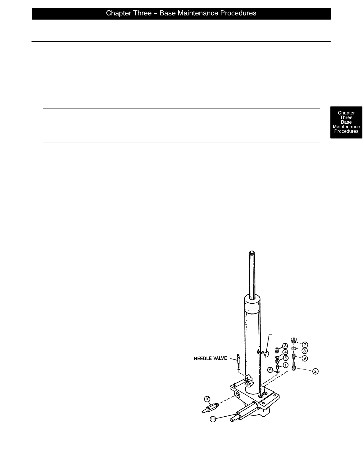
1. Remove the base plug (3) and the seal (4).
2. Remove the valve plug (5).
3. Using a stiff wire with a bent, pointed end, remove the valve (1).
4. Install the new valve (1) with the beveled end up (as shown in the illustration).
5. Reinstall the valve plug (5) with the beveled end down toward valve (1) and tighten to 10 foot–pounds
torque.
6. Reinstall the seal (4) and the base plug (3) and tighten to 10 foot–pounds torque.
7. Pump up the jack to the maximum height.
8. Be sure there are no hydraulic leaks before replacing the base hood and the litter.
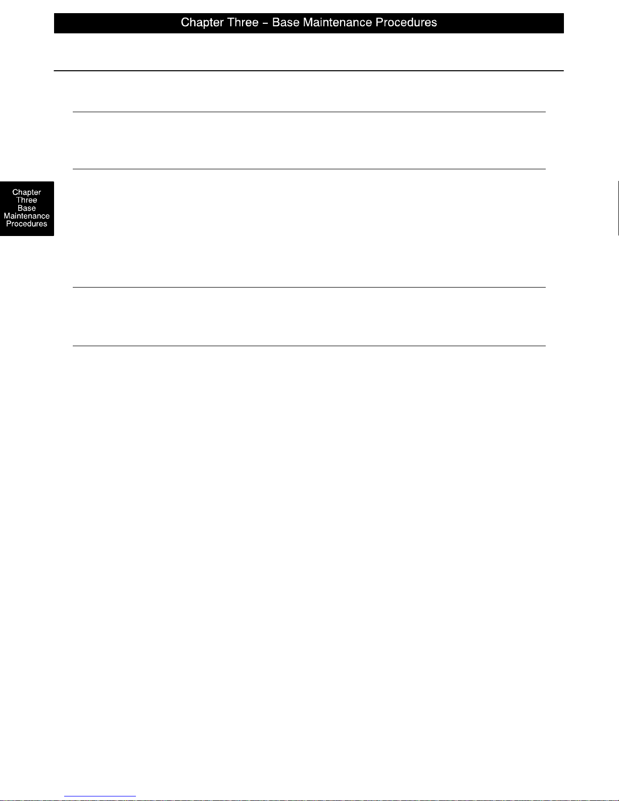
ITEM PART NO. PART NAME
1 926–20–153 Check Valve
2 715–1–341 Poppet
3 715–1–301 Base Plug
4 926–20–156 Seal
5 715–1–309 Valve Plug
6 926–20–154 Seal
7 715–1–301 Base Plug
8 926–20–156 Seal
9 390–2–134 Compression Spring
10 715–270–100 Valve Assembly*
10 2025–700–26 Valve Assembly**
11 715–100–325 Pump Piston
* Used on jack part number 1231–70–10.
** Used on jack part number 1231–70–210.
(See label on side of jack reservoir for jack
part number).
FILLER PLUG
page 3–11
Page 27
Hydraulic Jack Valve Replacement (Continued)
Replacement of Release Valve
WARNING
To avoid personal injury or damage to the stretcher, remove the litter and the base hood before beginning
service on the jacks. Lower the jack rod completely to relieve the pressure on the pump piston side of the
jack. This will prevent large hydraulic fluid loss and possible damage when the base plugs are removed.
1. Remove the release valve (10).
2. Install the new the release valve (10).
3. Pump up the jack to the maximum height.
4. Be sure there are no hydraulic leaks before replacing the base hood and the litter.
Replacement of Poppet Valve
WARNING
To avoid personal injury or damage to the stretcher, remove the litter and the base hood before beginning
service on the jacks. Lower the jack rod completely to relieve the pressure on the pump piston side of the
jack. This will prevent large hydraulic fluid loss and possible damage when the base plugs are removed.
1. Remove the base plug (7) and the seal (8).
2. Remove the compression spring (9).
3. Using small needle nose pliers, remove the poppet valve (2).
4. Install the new poppet valve (2).
5. Reinstall the compression spring (9).
6. Reinstall the seal (8) and the base plug (7) and tighten to 10 foot–pounds torque.
7. Pump up the jack to the maximum height to check its operation.
8. Check for hydraulic leaks before replacing the base hood and the litter.
page 3–12
Page 28
Base Lubrication
page 3–13
Page 29

Page 30
GENERAL INFORMATION
This section contains tool lists and step–by–step procedures to assist with the maintenance and servicing
of the litter portion of your equipment.
In the text, the words “right” and “left” refer to the right and left sides of a patient lying face up on the bed.
LITTER MAINTENANCE CONTENTS
Siderail Latch Adjustment 4–2. . . . . . . . . . . . . . . . . . . . . . . . . . . . . . . . . . . . . . . . . . . . . . . . . . . . . . . . . . . . . . .
Arm Board Counterbalance Adjustment 4–2. . . . . . . . . . . . . . . . . . . . . . . . . . . . . . . . . . . . . . . . . . . . . . . . . . .
Pneumatic Fowler Adjustment 4–3. . . . . . . . . . . . . . . . . . . . . . . . . . . . . . . . . . . . . . . . . . . . . . . . . . . . . . . . . . .
Pneumatic Fowler Release Handle Adjustment 4–4. . . . . . . . . . . . . . . . . . . . . . . . . . . . . . . . . . . . . . . . . . . . .
Pneumatic Cylinder Replacement 4–5. . . . . . . . . . . . . . . . . . . . . . . . . . . . . . . . . . . . . . . . . . . . . . . . . . . . . . . .
Articulating Head Piece Adjustment 4–6. . . . . . . . . . . . . . . . . . . . . . . . . . . . . . . . . . . . . . . . . . . . . . . . . . . . . . .
page 4–1
Page 31
Siderail Latch Adjustment
Required Tools:
1/8” Hex Allen Wrench
WARNING
The siderail latch adjustment is pre–set at the factory, and there should not normally be a need for readjustment. If adjustment must be done it is important to follow the procedure below. If it is not done properly, injury
to the patient or user could occur.
Adjustment Procedure:
1. Using a 1/8” hex Allen wrench, adjust the hex Allen screw located on the latch assembly opposite the
latch. T urning the screw clockwise will DECREASE the amount of play in the latching mechanism. Turn-
ing counterclockwise will INCREASE the amount.
NOTE
The amount of play in the siderail, when in full up engaged position, should be approximately 1/8 to 3/16 inches.
CAUTION
Too much play when the siderail is in the full up engaged position will give the siderail the appearance of being
unstable and could also cause premature wearing of the latch system.
Too little play will obstruct the latch and keep it from engaging completely in the full up position, which may
cause damage to the latch and/or injury to the patient or user.
Arm Board Counterbalance Adjustment
Required Tools:
7/16 Open End Wrench
Adjustment Procedure:
1. Raise the arm board to the full up position.
2. Unhook the extension spring at the eye bolt.
3. Using a 7/16 open end wrench, loosen the jam nut at the eye bolt.
4. Adjust the eye bolt to the desired position.
5. Tighten the jam nut.
6. Hook the extension spring to the eye bolt.
7. Allow the arm board to lower on its own.
8. Repeat steps 1–7 until the desired counterbalance is achieved.
page 4–2
Page 32
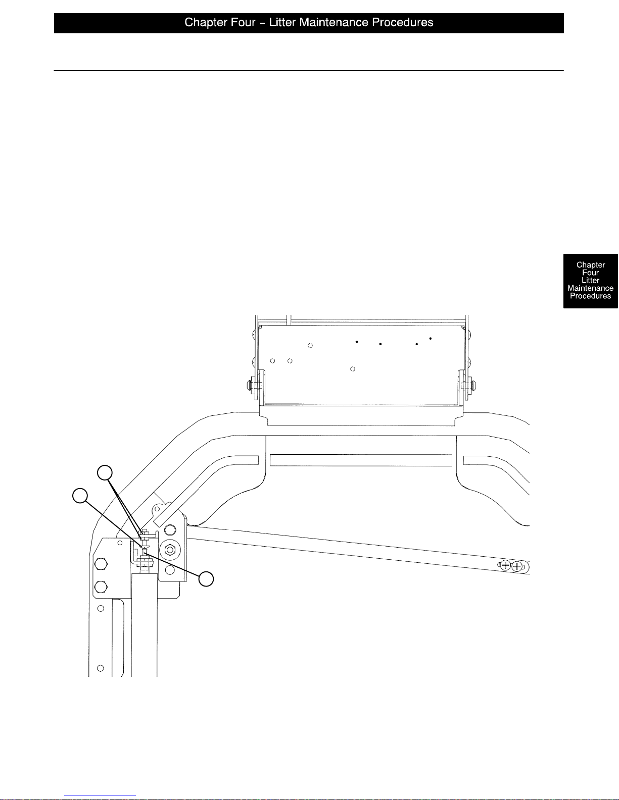
Pneumatic Fowler Adjustment
Required Tools:
(2) 3/8” Open End Wrenches
Adjustment Procedure:
1. Apply the stretcher brakes.
2. Pump the stretcher litter up to full height.
3. Move the Fowler to 70 or higher.
4. Using (2) 3/8” wrenches, loosen the two nuts (A) on the adjustment screw (B). If the Fowler is not holding
its position, turn the adjustment screw up, away from the release pin on the pneumatic cylinder (C). If
the Fowler is not releasing, turn the adjustment screw down, toward the release pin on the pneumatic
cylinder. Tighten the two nuts. Repeat for the other side of the Fowler.
5. To verify both sides of the Fowler are releasing equally , raise the Fowler to the full up position. Using two
hands, pull down on both sides of the Fowler, squeeze both release handles and verify both pneumatic
cylinders release equally. If they do not, repeat step four. When proper Fowler adjustment has been
verified, return the stretcher to service.
A
B
C
page 4–3
Page 33
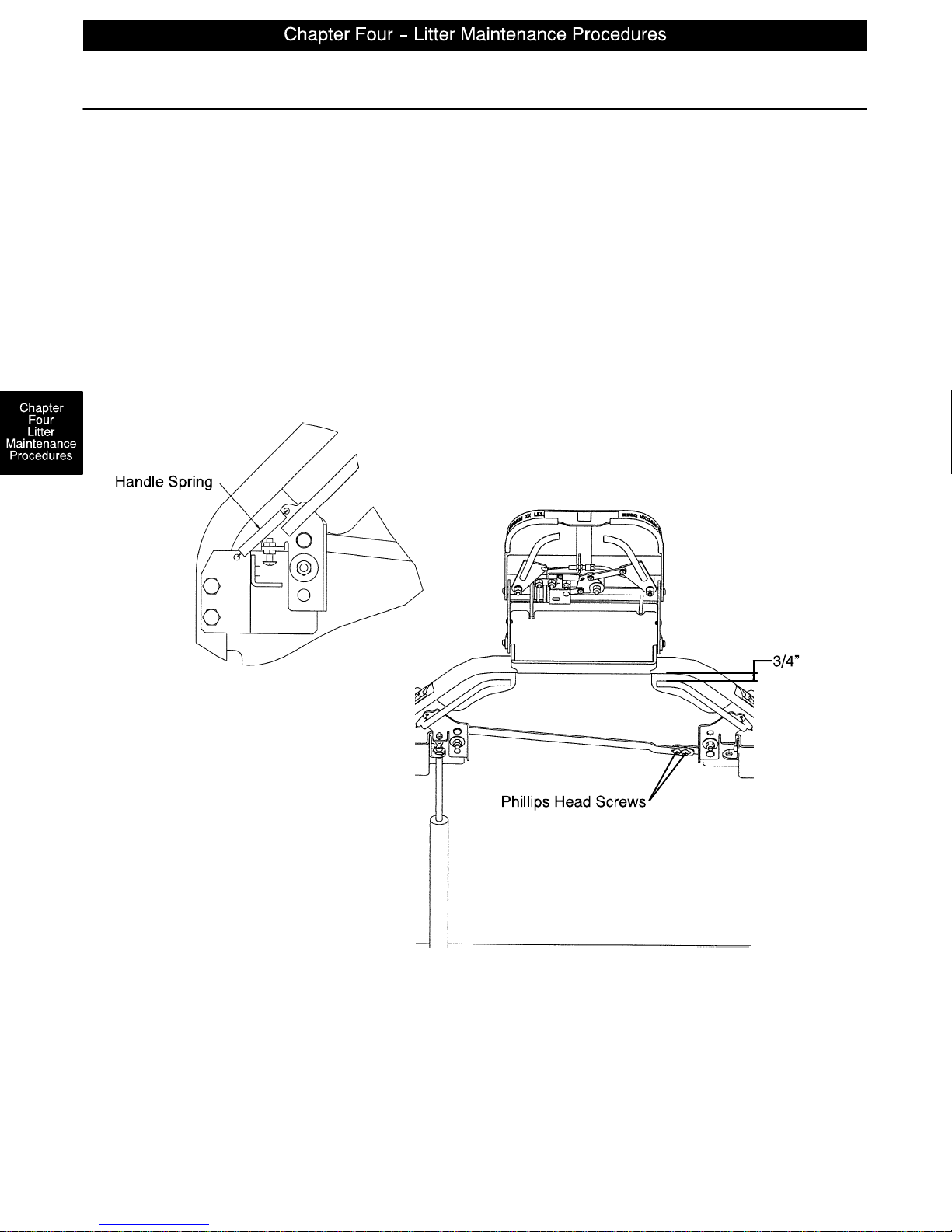
Pneumatic Fowler Release Handle Adjustment
Required Tools:
#2 Phillips Screwdriver
Adjustment Procedure:
1. Apply the stretcher brakes.
2. Loosen the two Phillips head screws on the handle linkage. Release the handle tension spring on the
patient’s left side.
3. Adjust the handles so there is a 3/4” gap between the inner Fowler frame and the handle.
4. Tighten the two screws on the handle linkage bar and reattach the spring.
5. It may be necessary to adjust the pneumatic cylinders (see page 4–3).
6. Verify proper Fowler operation before returning the stretcher to service.
page 4–4
Page 34
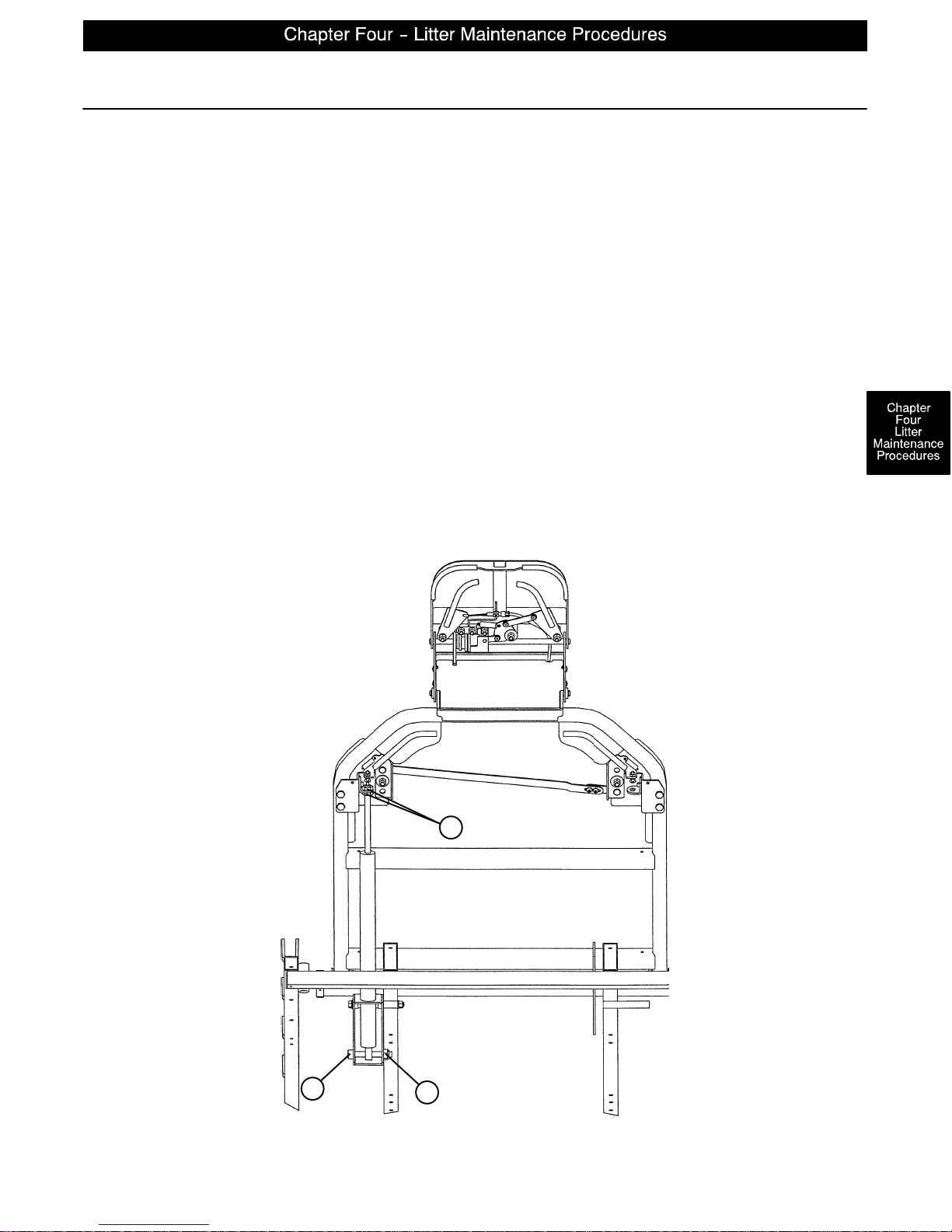
Pneumatic Cylinder Replacement
Required Tools:
(2) 17 mm. Wrenches 11/16” Open End Wrench 5/16” Hex Allen Wrench
Adjustment Procedure:
1. Apply the stretcher brakes.
2. Pump the litter up to full height.
3. Move the Fowler to 70.
4. Using two 17 mm. wrenches, remove both the large nuts (A) from the top of the pneumatic cylinder.
5. Using a 5/16” hex Allen wrench and an 11/16” open end wrench, remove the nut (B) and bolt (C) from
the bottom of the cylinder.
6. Raise the Fowler to 90 and remove the cylinder.
7. Press down on the release pin on the replacement cylinder to fully extend the cylinder.
8. Put the large nut on the new cylinder and screw it down securely.
9. Using a 5/16” hex Allen wrench and an 11/16” open end wrench, install the nut (B) and bolt (C) on the
bottom of the cylinder.
10. Check the Fowler adjustment (see page 4–3) before returning the stretcher to service.
C
A
B
page 4–5
Page 35
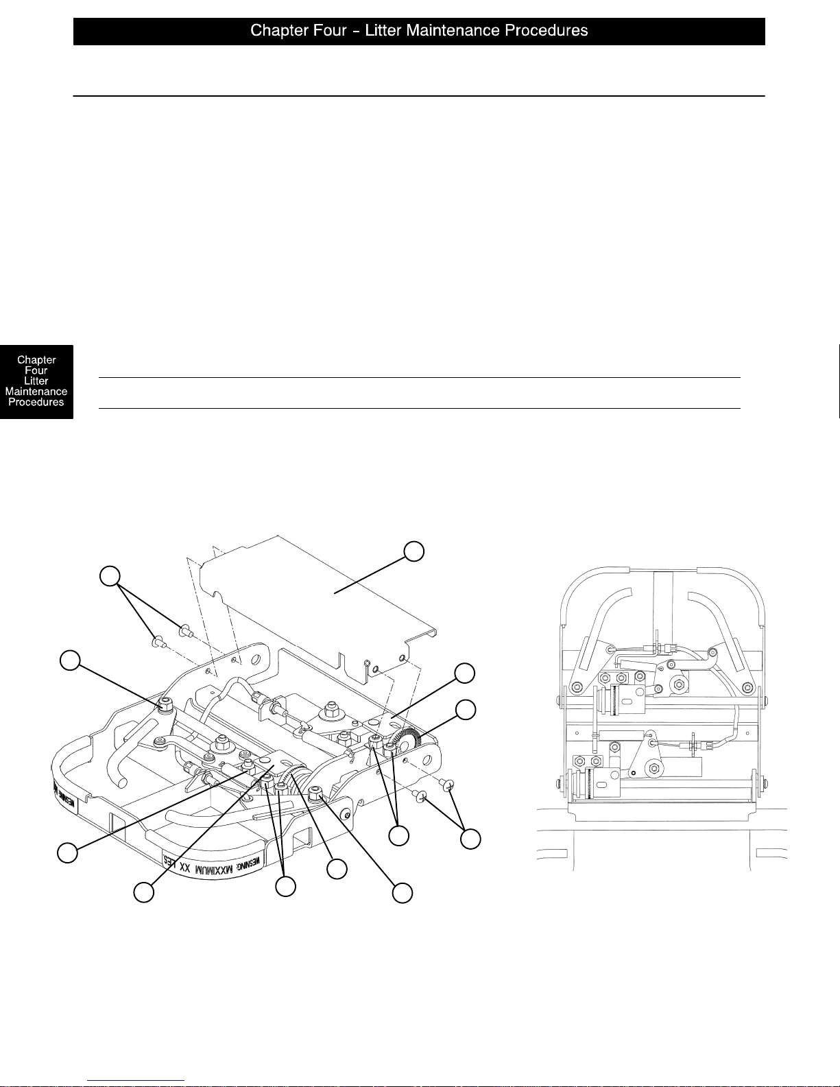
Articulating Head Piece Adjustment
Required Tools:
#2 Phillips Screwdriver 7/16” Socket and Ratchet Standard Screwdriver
Adjustment Procedure:
1. If the neck section is binding, the (patient) left handle needs adjustment. If the head section is binding,
the (patient) right handle needs adjustment. If you are adjusting the neck section handle, the 4 Phillips
head screws (A) holding the neck section cover (B) must be removed.
2. If the head or neck section is not returning to the full lock position, use a 7/16” socket and ratchet to loosen
the pivot nut (C).
3. If the torque block (E) is binding, use a 7/16” socket and ratchet to loosen the pivot nut (D).
4. If the section is still binding, check the torque block (E) for excess pressure against the gear (F). Using
a 7/16” socket and ratchet, loosen the two nuts (G) holding the gear adjustment block. Tighten the nuts
and verify the handle is releasing properly.
CAUTION
The dual articulating headpiece is designed to provide precision surgical positioning. Be sure to treat it with
care. The unit should be routinely checked to ensure optimal performance. In the event of any impact or
overload of the headpiece, be sure the unit is working properly and supports the intended load. Verify the
adjustment gears lock and release properly and, if necessary, perform the adjustment procedure.
B
A
C
G
D
F
E
G
C
E
F
A
page 4–6
Page 36
PART NAME
Arm Board 1068–55–10. . . . . . . . . . . . . . . . . . . . . . . . . . . . . . . . . . . . . . . . . . . . . . . . . . . . . .
Arm Board (with Direct Clamp) 1068–56–110. . . . . . . . . . . . . . . . . . . . . . . . . . . . . . . . . . . . .
Arm Board Clamp 1068–54–10. . . . . . . . . . . . . . . . . . . . . . . . . . . . . . . . . . . . . . . . . . . . . . . .
Brake Adjuster Assembly 715–201–150. . . . . . . . . . . . . . . . . . . . . . . . . . . . . . . . . . . . . . . . . .
Brake Adjuster Service Tool 715–700–150. . . . . . . . . . . . . . . . . . . . . . . . . . . . . . . . . . . . . . .
Brake/Steer Pedal, Removable 1069–70. . . . . . . . . . . . . . . . . . . . . . . . . . . . . . . . . . . .
Caster Cover Kit 1010–56–200. . . . . . . . . . . . . . . . . . . . . . . . . . . . . . . . . . . . . . . . . . . . . . . . .
Drape Support/Air Delivery System 1068–68. . . . . . . . . . . . . . . . . . . . . . . . . . . . . . . . .
Foot Board/Chartholder 741–34–100. . . . . . . . . . . . . . . . . . . . . . . . . . . . . . . . . . . . . . . . . . .
Foot Board/Defibrillator Tray 1010–50–100. . . . . . . . . . . . . . . . . . . . . . . . . . . . . . . . . . . . . . .
Head/Foot Board 741–29–100. . . . . . . . . . . . . . . . . . . . . . . . . . . . . . . . . . . . . . . . . . . . . . . . .
Head Pad, 2” Concave 1069–81. . . . . . . . . . . . . . . . . . . . . . . . . . . . . . . . . . . . . . . . . . . .
Head Pad, 3” Concave 1069–181. . . . . . . . . . . . . . . . . . . . . . . . . . . . . . . . . . . . . . . . . . . .
Head Pad, 1” Flat 1069–78. . . . . . . . . . . . . . . . . . . . . . . . . . . . . . . . . . . . . . . . . . . . . . . .
Head Pad, 2” Flat 1069–179. . . . . . . . . . . . . . . . . . . . . . . . . . . . . . . . . . . . . . . . . . . . . . . .
Head Pad, 3” Flat 1069–180. . . . . . . . . . . . . . . . . . . . . . . . . . . . . . . . . . . . . . . . . . . . . . . .
Head Pad, 3” Inflatable, Ultra–Comfort 1069–82. . . . . . . . . . . . . . . . . . . . . . . . . . . . . .
Head Pad, Inflatable, Non–Latex Bulb Only 1066–82–20. . . . . . . . . . . . . . . . . . . . . . . . .
Hydraulic Oil, Mobil Aero HFA – 1 Quart 2020–70–475. . . . . . . . . . . . . . . . . . . . . . . . . . . .
Hydraulic Jack, Constant Descent 1231–70–210. . . . . . . . . . . . . . . . . . . . . . . . . . . . . . . . . .
Hydraulic Jack, Variable Descent 1231–70–10. . . . . . . . . . . . . . . . . . . . . . . . . . . . . . . . . . .
Hydraulic Jack Pump Piston Assembly 715–200–325. . . . . . . . . . . . . . . . . . . . . . . . . . . . . .
Hydraulic Jack Spring Compression Tool 1210–1–3. . . . . . . . . . . . . . . . . . . . . . . . . . . .
Instrument/Serving Tray 1052–129. . . . . . . . . . . . . . . . . . . . . . . . . . . . . . . . . . . . . . . . . . .
I.V. Caddy 1050–1–100. . . . . . . . . . . . . . . . . . . . . . . . . . . . . . . . . . . . . . . . . . . . . . . . . . . . . . .
I.V. Caddy w/Mounting Clip 1050–2. . . . . . . . . . . . . . . . . . . . . . . . . . . . . . . . . . . . . . . .
I.V. Pole, Standard Removable 390–25. . . . . . . . . . . . . . . . . . . . . . . . . . . . . . . . . . . .
I.V. Pole, 2–Stage Permanent, Foot End 1010–80–100. . . . . . . . . . . . . . . . . . . . . . . . . . . .
I.V. Pole, 3–Stage Permanent, Foot End 1020–62. . . . . . . . . . . . . . . . . . . . . . . . . . . .
Mattress, 2” Thick x 26” Wide, Standard, Dual Articulation 1069–26–50. . . . . . . . . . . . .
Mattress, 3” Thick x 26” Wide, Standard, Dual Articulation 1069–26–60. . . . . . . . . . . . .
Mattress, 4” Thick x 26” Wide, Standard, Dual Articulation 1069–26–90. . . . . . . . . . . . .
Mattress, 3” Thick x 26” Wide, Enhanced Comfort, Dual Articulation 1069–26–70. . . .
Mattress, 4” Thick x 26” Wide, Enhanced Comfort, Dual Articulation 1069–26–80. . . .
Mattress, 3” Thick x 26” Wide, Standard, Zero Articulation 1069–26–10. . . . . . . . . . . . .
Mattress, 3” Thick x 26” Wide, Enhanced Comfort, Zero Articulation 1069–26–20. . . .
Mattress, 4” Thick x 26” Wide, Enhanced Comfort, Zero Articulation 1069–26–30. . . .
Neck Pad, Enhanced Clearance Only 1068–236–10. . . . . . . . . . . . . . . . . . . . . . . . . . . . . . .
Oxygen Bottle Holder 1010–30. . . . . . . . . . . . . . . . . . . . . . . . . . . . . . . . . . . . . . . . . . . . .
PART NUMBER
page 5–1
Page 37
PART NAME
Pads, Pre–Op/Post–Op Head Piece, 2” 1069–62. . . . . . . . . . . . . . . . . . . . . . . . . . . . .
Pads, Pre–Op/Post–Op Head Piece, 3” 1069–60. . . . . . . . . . . . . . . . . . . . . . . . . . . . .
Pads, Pre–Op/Post–Op Head Piece, 3”, Ultra–Comfort 1069–63. . . . . . . . . . . . . . .
Pads, Pre–Op/Post–Op Head Piece, 4” Enhanced Comfort 1069–64. . . . . . . . . . . .
Pads, Pre–Op/Post–Op Head Piece, 4” Ultra–Comfort 1069–64–5. . . . . . . . . . . . . . . .
Paint, Touch–Up, Gloss Black, Bottle w/Brush 7000–1–322. . . . . . . . . . . . . . . . . . . . . . .
Paint, Touch–Up, Gloss Black, Spray Can 7000–1–319. . . . . . . . . . . . . . . . . . . . . . . . . . .
Paint, Touch–Up, Gray, Bottle w/Brush 7000–1–320. . . . . . . . . . . . . . . . . . . . . . . . . . . . . .
Paint, Touch–Up, Gray, Spray Can 7000–1–317. . . . . . . . . . . . . . . . . . . . . . . . . . . . . . . . .
Restraint Strap, Ankle 946–43–100. . . . . . . . . . . . . . . . . . . . . . . . . . . . . . . . . . . . . . . . . . . .
Restraint Strap, Body 390–19. . . . . . . . . . . . . . . . . . . . . . . . . . . . . . . . . . . . . . . . . . . . .
Restraint Strap, Chest 1010–58. . . . . . . . . . . . . . . . . . . . . . . . . . . . . . . . . . . . . . . . . . . .
Restraint Strap, Wrist 946–44–100. . . . . . . . . . . . . . . . . . . . . . . . . . . . . . . . . . . . . . . . . . . . .
Restraint Straps, Full Patient Security Package 1010–77. . . . . . . . . . . . . . . . . . . . . .
Siderail Kit, 3–Position 1068–700–1. . . . . . . . . . . . . . . . . . . . . . . . . . . . . . . . . . . . . . . . . . . .
Siderail Pads 1010–52. . . . . . . . . . . . . . . . . . . . . . . . . . . . . . . . . . . . . . . . . . . . . . . . . . . .
Surgery Accessory Rail 1068–266. . . . . . . . . . . . . . . . . . . . . . . . . . . . . . . . . . . . . . . . . . .
Transfer Board Assembly 1060–58. . . . . . . . . . . . . . . . . . . . . . . . . . . . . . . . . . . . . . . . .
Wrist Rest, Superior 1068–50. . . . . . . . . . . . . . . . . . . . . . . . . . . . . . . . . . . . . . . . . . . . . .
Wrist Rest, Temporal 1068–51. . . . . . . . . . . . . . . . . . . . . . . . . . . . . . . . . . . . . . . . . . . . .
Wrist Rest Mounting Bracket, Superior 1069–33–205. . . . . . . . . . . . . . . . . . . . . . . . . . . . . .
PART NUMBER
page 5–2
Page 38
GENERAL INFORMATION
This section contains assembly drawings and parts lists to assist with the identification of individual components of the equipment and accessories.
In the parts lists, the words “right” and “left” refer to the right and left sides of a patient lying face up on the
bed.
ASSEMBLY DRAWINGS AND PARTS LISTS CONTENTS
Side Control Base Assembly page 6–3 – 6–6. . . . . . . . . . . . . . . . . . . . . . . . . . . . . . . . . . . . . . . . . . . . . . . . . . .
End Control Base Assembly page 6–7 – 6–10. . . . . . . . . . . . . . . . . . . . . . . . . . . . . . . . . . . . . . . . . . . . . . . . .
Brake Adjuster Assembly page 6–11. . . . . . . . . . . . . . . . . . . . . . . . . . . . . . . . . . . . . . . . . . . . . . . . . . . . . . . . . .
Brake Cam Assembly page 6–12. . . . . . . . . . . . . . . . . . . . . . . . . . . . . . . . . . . . . . . . . . . . . . . . . . . . . . . . . . . . .
Side Control Pump Pedal Assembly page 6–13. . . . . . . . . . . . . . . . . . . . . . . . . . . . . . . . . . . . . . . . . . . . . . . .
Foot End Pump Pedal Assembly page 6–14. . . . . . . . . . . . . . . . . . . . . . . . . . . . . . . . . . . . . . . . . . . . . . . . . . .
Head End Pump Pedal Assembly page 6–15. . . . . . . . . . . . . . . . . . . . . . . . . . . . . . . . . . . . . . . . . . . . . . . . . .
Constant Flow Jack Assembly 6–18. . . . . . . . . . . . . . . . . . . . . . . . . . . . . . . . . . . . . . . . . . . . . . . . . . . . . . . . . .
Constant Flow Jack Base Assembly 6–19. . . . . . . . . . . . . . . . . . . . . . . . . . . . . . . . . . . . . . . . . . . . . . . . . . . . .
Jack Pump Piston Assembly 6–20. . . . . . . . . . . . . . . . . . . . . . . . . . . . . . . . . . . . . . . . . . . . . . . . . . . . . . . . . . . .
Base Assembly with Steerlock Caster Option 6–21. . . . . . . . . . . . . . . . . . . . . . . . . . . . . . . . . . . . . . . . . . . . .
Caster Assembly with Steerlock 6–22. . . . . . . . . . . . . . . . . . . . . . . . . . . . . . . . . . . . . . . . . . . . . . . . . . . . . . . . .
Standard Caster Assembly 6–23. . . . . . . . . . . . . . . . . . . . . . . . . . . . . . . . . . . . . . . . . . . . . . . . . . . . . . . . . . . . .
Base Assembly with Fifth Wheel Option 6–24. . . . . . . . . . . . . . . . . . . . . . . . . . . . . . . . . . . . . . . . . . . . . . . . . .
Pivot Rod Assembly 6–25. . . . . . . . . . . . . . . . . . . . . . . . . . . . . . . . . . . . . . . . . . . . . . . . . . . . . . . . . . . . . . . . . . .
Fifth Wheel Arm Assembly 6–26. . . . . . . . . . . . . . . . . . . . . . . . . . . . . . . . . . . . . . . . . . . . . . . . . . . . . . . . . . . . .
Optional Side Control Brake Assembly 6–28, 6–29. . . . . . . . . . . . . . . . . . . . . . . . . . . . . . . . . . . . . . . . . . . . .
Optional Uni–Lower Pedal Assembly 6–30. . . . . . . . . . . . . . . . . . . . . . . . . . . . . . . . . . . . . . . . . . . . . . . . . . . . .
Optional Dual Lowering Pedal Assembly 6–31. . . . . . . . . . . . . . . . . . . . . . . . . . . . . . . . . . . . . . . . . . . . . . . . .
Base Labeling Assembly 6–32 – 6–34. . . . . . . . . . . . . . . . . . . . . . . . . . . . . . . . . . . . . . . . . . . . . . . . . . . . . . . .
Litter Assembly 6–35 – 6–37. . . . . . . . . . . . . . . . . . . . . . . . . . . . . . . . . . . . . . . . . . . . . . . . . . . . . . . . . . . . . . . .
Foot End Jack Support Assembly 6–38. . . . . . . . . . . . . . . . . . . . . . . . . . . . . . . . . . . . . . . . . . . . . . . . . . . . . . .
Head End Jack Support Assembly 6–39. . . . . . . . . . . . . . . . . . . . . . . . . . . . . . . . . . . . . . . . . . . . . . . . . . . . . . .
Zero Articulating Pneumatic Fowler Assembly 6–41– 6–45. . . . . . . . . . . . . . . . . . . . . . . . . . . . . . . . . . . . . . .
Single Articulating Pneumatic Fowler Assembly 6–46– 6–51. . . . . . . . . . . . . . . . . . . . . . . . . . . . . . . . . . . . .
Dual Articulating Pneumatic Fowler Assembly 6–52 – 6–57. . . . . . . . . . . . . . . . . . . . . . . . . . . . . . . . . . . . . .
Zero Articulating Crank Fowler Assembly 6–58, 6–59. . . . . . . . . . . . . . . . . . . . . . . . . . . . . . . . . . . . . . . . . . .
Single Articulating Crank Fowler Assembly 6–60 – 6–62. . . . . . . . . . . . . . . . . . . . . . . . . . . . . . . . . . . . . . . .
Dual Articulating Crank Fowler Assembly 6–64– 6–67. . . . . . . . . . . . . . . . . . . . . . . . . . . . . . . . . . . . . . . . . . .
Crank Fowler Assembly 6–68. . . . . . . . . . . . . . . . . . . . . . . . . . . . . . . . . . . . . . . . . . . . . . . . . . . . . . . . . . . . . . . .
page 6–1
Page 39
ASSEMBLY DRAWINGS AND PARTS LISTS CONTENTS (CONTINUED)
Fowler Crankscrew Assembly 6–69. . . . . . . . . . . . . . . . . . . . . . . . . . . . . . . . . . . . . . . . . . . . . . . . . . . . . . . . . . .
Dual Articulating Head Piece Assembly 6–70 – 6–73. . . . . . . . . . . . . . . . . . . . . . . . . . . . . . . . . . . . . . . . . . .
Stationary Foot Section Assembly 6–74. . . . . . . . . . . . . . . . . . . . . . . . . . . . . . . . . . . . . . . . . . . . . . . . . . . . . . .
Knee Gatch Assembly 6–75. . . . . . . . . . . . . . . . . . . . . . . . . . . . . . . . . . . . . . . . . . . . . . . . . . . . . . . . . . . . . . . . .
Foot and Thigh Section Assembly 6–76. . . . . . . . . . . . . . . . . . . . . . . . . . . . . . . . . . . . . . . . . . . . . . . . . . . . . . .
Knee Gatch Crankscrew Assembly 6–77. . . . . . . . . . . . . . . . . . . . . . . . . . . . . . . . . . . . . . . . . . . . . . . . . . . . . .
Siderail to Litter Assembly, Two–Position Siderails 6–78. . . . . . . . . . . . . . . . . . . . . . . . . . . . . . . . . . . . . . . . .
Two–Position Siderail Assembly 6–79. . . . . . . . . . . . . . . . . . . . . . . . . . . . . . . . . . . . . . . . . . . . . . . . . . . . . . . . .
Siderail to Litter Assembly, Three–Position Siderails 6–80. . . . . . . . . . . . . . . . . . . . . . . . . . . . . . . . . . . . . . .
Three–Position Siderail Assembly 6–81. . . . . . . . . . . . . . . . . . . . . . . . . . . . . . . . . . . . . . . . . . . . . . . . . . . . . . .
Optional Transfer System Assembly 6–82. . . . . . . . . . . . . . . . . . . . . . . . . . . . . . . . . . . . . . . . . . . . . . . . . . . . .
Optional Transfer Board Assembly, Left 6–83. . . . . . . . . . . . . . . . . . . . . . . . . . . . . . . . . . . . . . . . . . . . . . . . . .
Optional Transfer Board Assembly, Right 6–84. . . . . . . . . . . . . . . . . . . . . . . . . . . . . . . . . . . . . . . . . . . . . . . . .
Optional Transfer Board Support Assembly 6–85. . . . . . . . . . . . . . . . . . . . . . . . . . . . . . . . . . . . . . . . . . . . . . .
Optional Pre–Op Post–Op Head Piece Mounting Assembly 6–86, 6–87. . . . . . . . . . . . . . . . . . . . . . . . . . .
Optional Pre–Op Post–Op Head Piece Assembly 6–88, 6–89. . . . . . . . . . . . . . . . . . . . . . . . . . . . . . . . . . . .
Standard, Removable I.V. Pole Assembly 6–90. . . . . . . . . . . . . . . . . . . . . . . . . . . . . . . . . . . . . . . . . . . . . . . . .
Optional 2–Stage I.V. Pole Assembly 6–91, 6–92. . . . . . . . . . . . . . . . . . . . . . . . . . . . . . . . . . . . . . . . . . . . . .
Optional 3–Stage I.V. Pole Assembly 6–93–6–95. . . . . . . . . . . . . . . . . . . . . . . . . . . . . . . . . . . . . . . . . . . . . .
Optional I.V. Pole Latch Assembly 6–96. . . . . . . . . . . . . . . . . . . . . . . . . . . . . . . . . . . . . . . . . . . . . . . . . . . . . . .
Optional Foot Board/Chartholder Assembly 6–97. . . . . . . . . . . . . . . . . . . . . . . . . . . . . . . . . . . . . . . . . . . . . . .
Optional Upright Oxygen Bottle Holder Assembly 6–97. . . . . . . . . . . . . . . . . . . . . . . . . . . . . . . . . . . . . . . . . .
Optional Foot Board Extension/Defibrillator Tray Assembly 6–98. . . . . . . . . . . . . . . . . . . . . . . . . . . . . . . . . .
Optional Wrist Rest Assembly 6–99, 6–100. . . . . . . . . . . . . . . . . . . . . . . . . . . . . . . . . . . . . . . . . . . . . . . . . . . .
Optional Drape Support Assembly 6–101. . . . . . . . . . . . . . . . . . . . . . . . . . . . . . . . . . . . . . . . . . . . . . . . . . . . . .
Optional Accessory Rail Assembly 6–102. . . . . . . . . . . . . . . . . . . . . . . . . . . . . . . . . . . . . . . . . . . . . . . . . . . . . .
Optional Arm Board Assembly 6–103, 6–104. . . . . . . . . . . . . . . . . . . . . . . . . . . . . . . . . . . . . . . . . . . . . . . . . .
Mattresses and Siderail Pads 6–105. . . . . . . . . . . . . . . . . . . . . . . . . . . . . . . . . . . . . . . . . . . . . . . . . . . . . . . . . .
page 6–2
Page 40
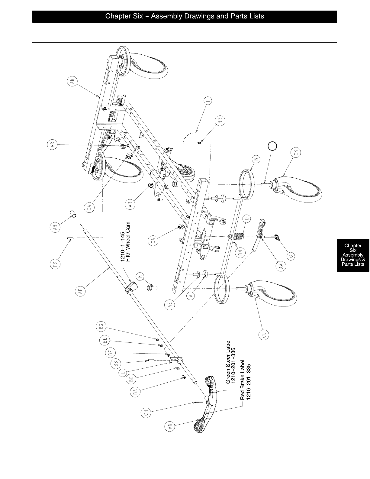
FOOT END
Side Control Base Assembly
CJ
HEAD END
Assembly part number 1068–1–210 (reference only)
page 6–3
Page 41
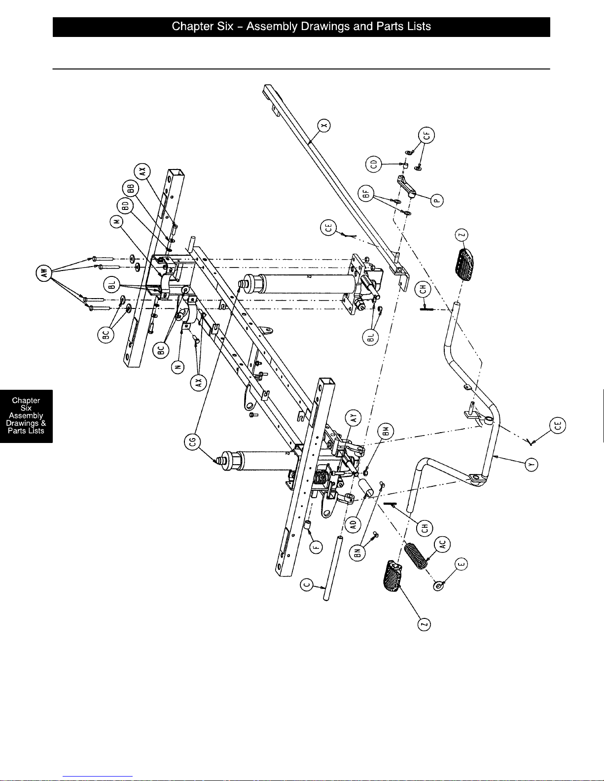
HEAD END
Side Control Base Assembly
Assembly part number 1068–1–210 (reference only)
page 6–4
FOOT END
Page 42
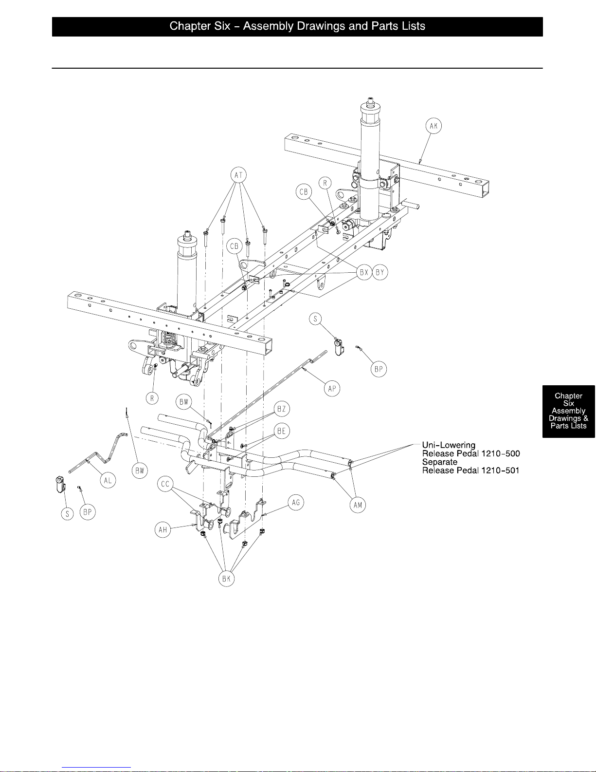
Side Control Base Assembly
Assembly part number 1068–1–210 (reference only)
HEAD END
FOOT END
page 6–5
Page 43
Side Control Base Assembly
Item Part No. Part Name Qty. Item Part No. Part Name Qty.
A 715–1–11 Brake Cushion 4 AW 3–62 Hex Hd. Cap Screw 8
B 715–1–61 Caster Brake Weldment 2 AX 3–85 Hex Hd. Cap Screw 8
C 715–1–92 Pump Pedal Shaft 1 AY 4–146 Soc. Hd. Cap Screw 2
D 715–201–94 Compression Spring 2 BA 8–17 Shoulder Bolt 2
E 715–1–133 Collar 1 BB 11–3 Washer 12
F 715–1–140 Vinyl Tube 1 BC 11–262 Washer 12
G (page 6–11) Brake Adjuster 2 BD 13–38 Ext. Tooth Lock Washer 4
H 715–1–156 Ground Chain 1 BE 14–2 Washer 6
K 715–1–158 Caster Nut 4 BF 14–9 Washer 2
L 715–1–165 Actuator Plate Weldment 2 BG 16–2 Hex Nut 2
M 715–1–192 Jack Support 2 BK 16–28 Hex Nut 4
N 715–1–193 Jack Support Clamp 2 BL 16–36 Hex Nut 16
P 715–1–214 Connecting Link 1 BM 16–48 Hex Nut 2
R 715–1–333 Release Rod Stop Sleeve 2 BN 21–22 Set Screw 2
S 715–1–346 Release Paddle 2 BP 21–50 Set Screw 2
X 715–201–27 Pump Rod Assembly 1 BR 23–25 Self–Tapping Screw 1
Y (page 6–13) Pump Pedal Assembly 1 BS 26–13 Spring Pin 2
Z 715–201–126 Slip–On Pump Pedal 2 BW 27–4 Cotter Pin 2
AA (page 6–12) Brake Cam Assembly 2 BX 29–7 Velcro Loop 6
AB 37–237 Round Vinyl Cap 1 BY 29–9 Velcro Pile 6
AC 38–246 Jack Spring 1 BZ 38–355 Extension Spring 2
AD 763–1–16 Spring Holder 1 CA 42–20 Collar 2
AE 946–1–116 Brake Bar Bushing 4 CB 52–245 Nyliner 2
AF 1068–201–45 Brake/Steer Rod Ass’y 1 CC 52–747 Flange Bearing 4
AG 1210–1–114 Pedal Pivot, Left 1 CD 52–284 Spacer Washer 1
AH 1210–1–115 Pedal Pivot, Right 1 CE 27–3 Cotter Pin 2
AK 1210–201–120 Base Frame Weldment 1 CF 11–4 Washer 2
AL 1210–201–139 Pull Release Rod, Head 1 CG (page 6–16) Jack Assembly 2
AM 1210–201–152 Release Pedal Weldment 2 (page 6–18) Constant Flow Jack Ass’y2
AN 1210–201–153 Butterfly “V” Pedal 1 CH 26–143 Groove Pin 3
AP 1210–201–222 Push Release Rod 1 CJ (page 6–23) Caster Assembly *
AR 1210–201–251 Insert 3 CK 715–1–265 Wheel Cover, Right 4
AT 3–47 Hex Hd. Cap Screw 4 CL 715–1–266 Wheel Cover, Left 4
* Caster assembly is quantity of 4 if the fifth wheel option is present on the stretcher and quantity of 3 if the steering caster
option is present.
page 6–6
Page 44
HEAD END
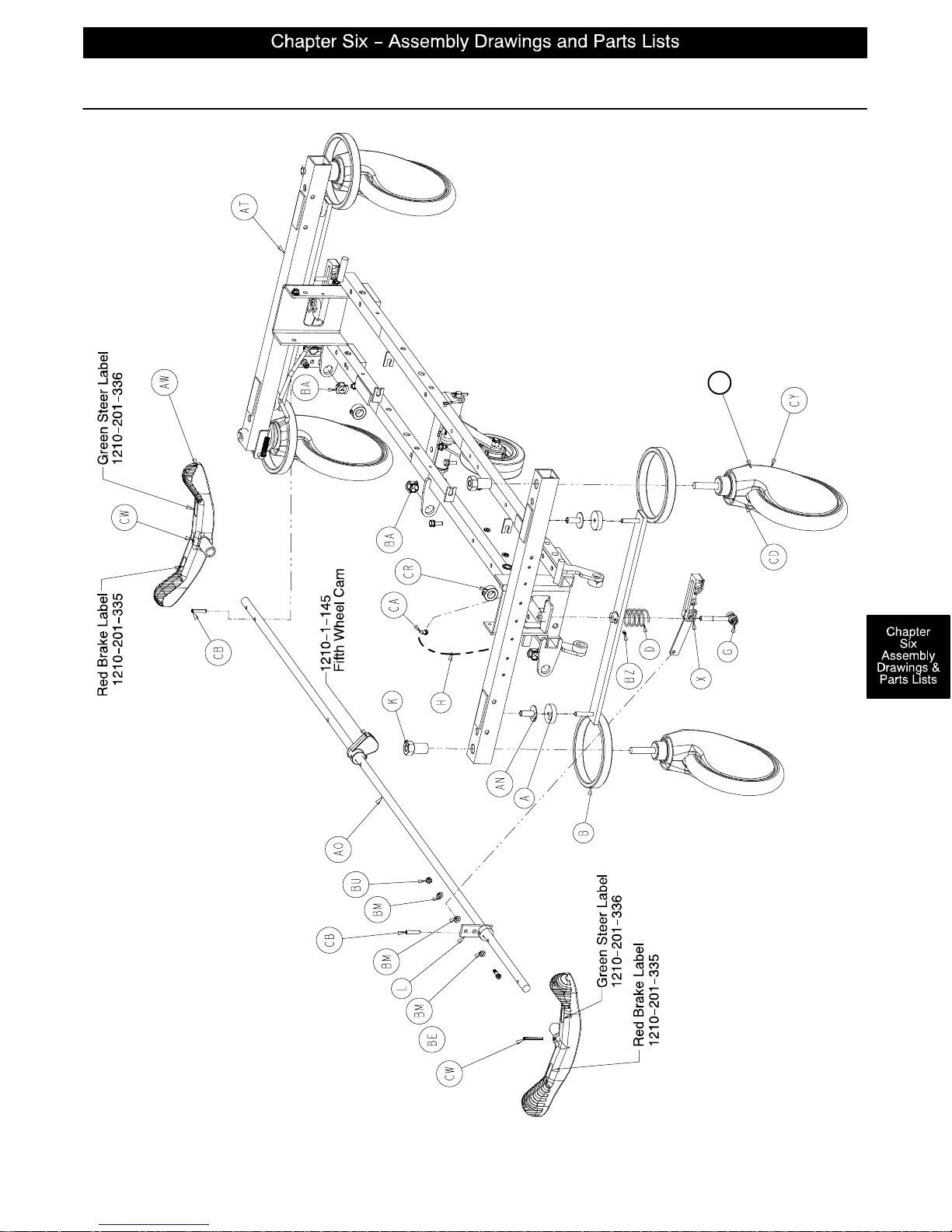
End Control Base Assembly
CV
Assembly part number 1068–2–210 (reference only)
FOOT END
page 6–7
Page 45
HEAD END
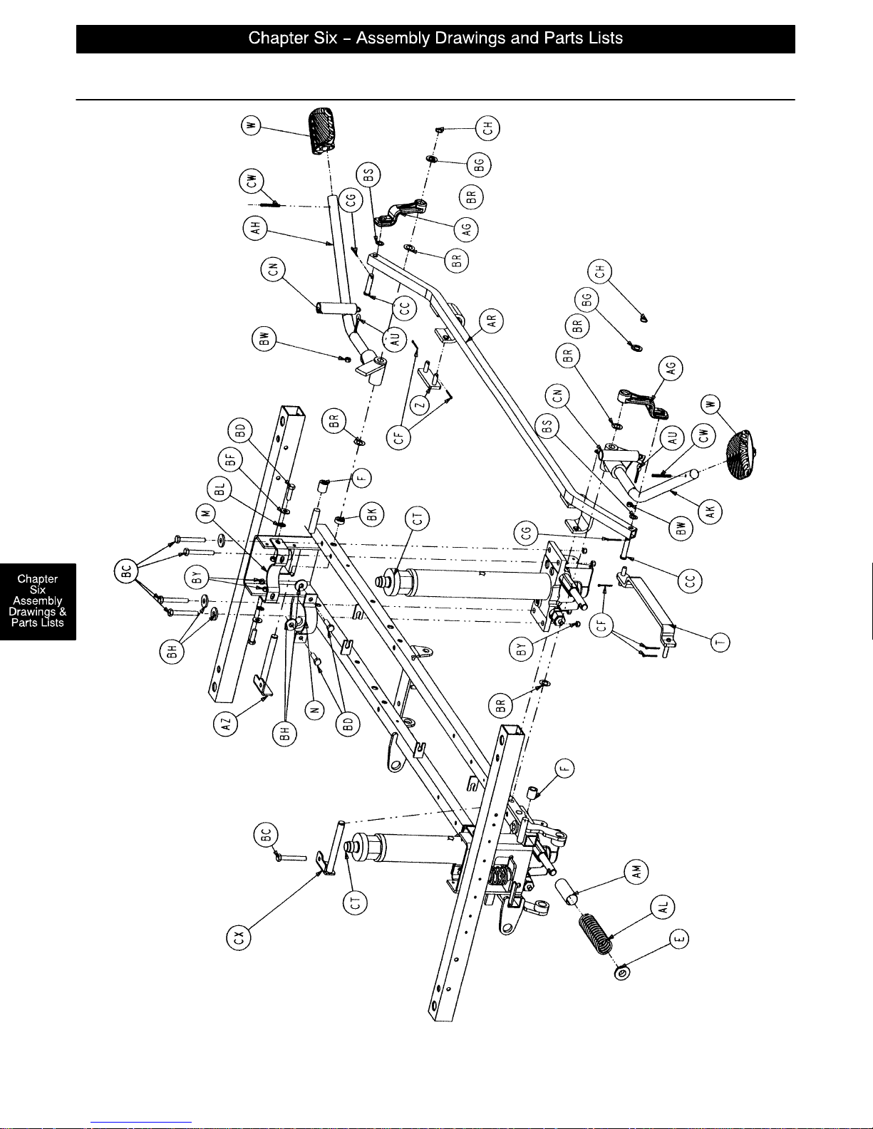
End Control Base Assembly
Assembly part number 1068–2–210 (reference only)
page 6–8
FOOT END
Page 46
FOOT END
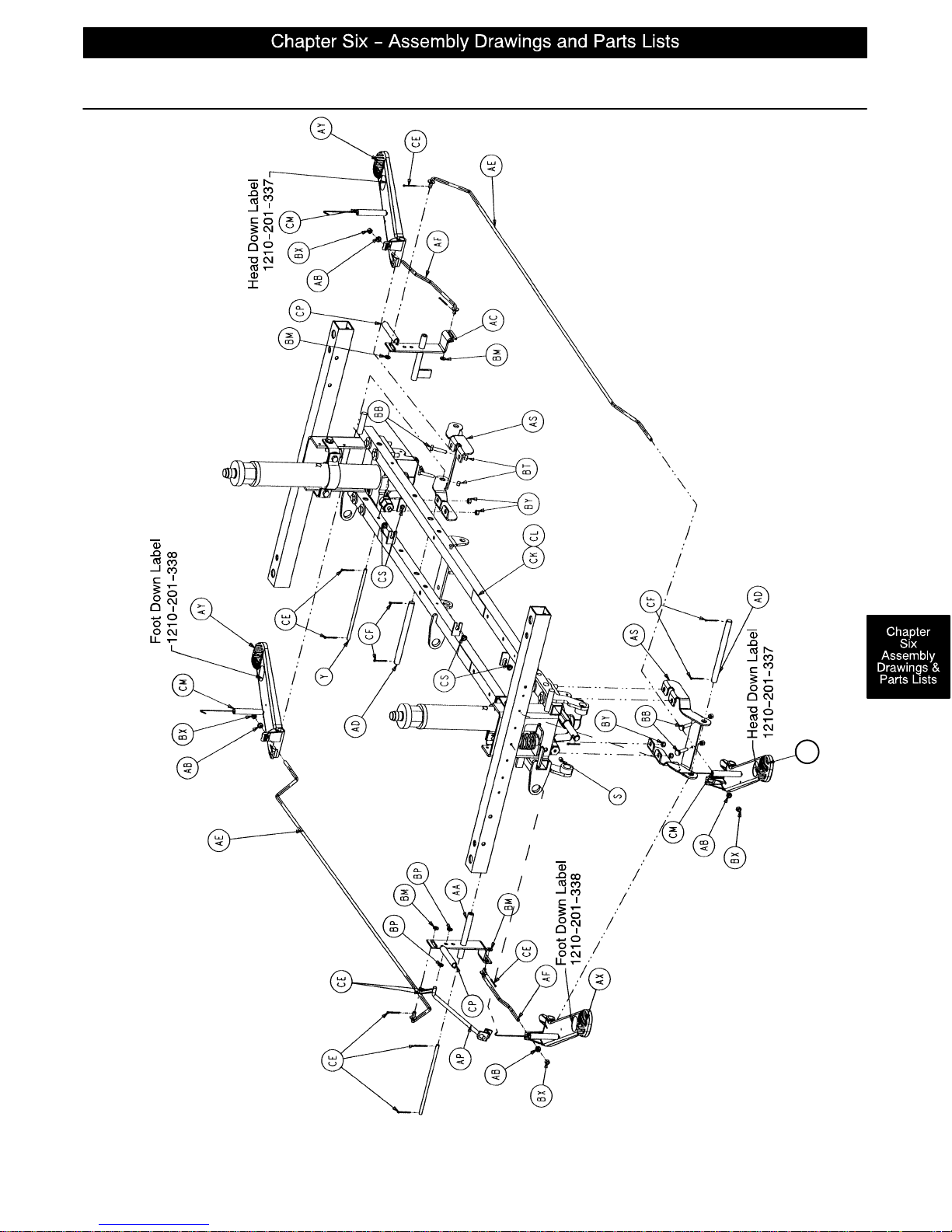
End Control Base Assembly
HEAD END
AX
page 6–9
Page 47
End Control Base Assembly
Item Part No. Part Name Qty. Item Part No. Part Name Qty.
A 715–1–11 Brake Cushion 4 BB 3–4 Hex Hd. Cap Screw 4
B 715–1–61 Caster Brake Weldment 2 BC 3–62 Hex Hd. Cap Screw 8
D 715–201–94 Compression Spring 2 BD 3–85 Hex Hd. Cap Screw 8
E 715–1–133 Collar 2 BE 8–17 Shoulder Bolt 2
F 715–1–140 Vinyl Tube 2 BF 11–3 Washer 4
G (page 6–11) Brake Adjuster 2 BG 11–13 Washer 2
H 715–1–156 Ground Chain 1 BH 11–262 Washer 10
K 715–1–158 Caster Nut 4 BK 11–350 Spacer Washer 1
L 715–1–165 Actuator Plate Weldment 2 BL 13–38 Ext. Tooth Lock Washer 4
M 715–1–192 Jack Support 2 BM 14–2 Washer 7
N 715–1–193 Jack Support Clamp 2 BP 14–3 Washer 2
S 715–1–333 Release Rod Stop Sleeve 2 BR 14–7 Washer 4
T 716–1–109 Pump Link, Head End 1 BS 14–9 Washer 2
W 715–201–126 Slip–On Pump Pedal 2 BT 15–11 Hex Nut 4
X (page 6–12) Brake Cam Assembly 2 BU 16–2 Hex Nut 2
Y 716–1–15 Release Pivot Bar 2 BW 16–14 Nylock Nut 2
Z 716–1–102 Pump Link, Foot End 1 BX 16–102 Hex Nut 4
AA 716–1–119 Pivot Ass’y, Head End 1 BY 16–36 Hex Nut 16
AB 716–1–286 Release Ball Spacer 4 BZ 21–151 Set Screw 2
AC 716–1–52 Pivot Ass’y, Foot End 1 CA 23–25 Self–Tapping Screw 1
AD 716–201–61 Rel. Pedal Pivot Rod 2 CB 26–13 Spring Pin 2
AE 716–201–70 Long Release Rod 2 CC 26–195 Clevis Pin 2
AF 716–201–74 Release Rod 2 CD 715–1–265 Wheel Cover, Right 4
AG 716–201–281 Pump Idler Link 2 CE 27–4 Cotter Pin 9
AH (page 6–14) Pump Pedal Ass’y, Ft. End 1 CF 27–3 Cotter Pin 9
AK (page 6–15) Pump Pedal Ass’y, Hd. End 1 CG 27–16 Cotter Pin 2
AL 763–1–15 Jack Spring 1 CH 28–97 External Retaining Ring 2
AM 763–1–16 Spring Holder 1 CK 29–7 Dual Lock 6
AN 946–1–116 Brake Bar Bushing 4 CL 29–9 Dual Lock 6
AO 715–201–230 Brake/Steer Rod Ass’y 1 CM 38–235 Descent Pedal Ret. Spring 4
AP 1210–1–112 Rel. Rod, Head End, Left 1 CN 38–251 Pump Return Spring 2
AR 1210–201–27 Pump Rod Angle 1 CP 38–326 Extension Spring 2
AS 1210–201–111 End Rel. Pedal Bracket 2 CR 42–20 Collar 2
AT 1210–201–120 Base Frame Weldment 1 CS 52–245 Nyliner 4
AU 1210–201–551 Eye Bolt 2 CT (page 6–16) Jack Assembly 2
AW 1210–201–153 Butterfly “V” Pedal 2 (page 6–18) Constant Flow Jack Ass’y2
AX 1210–201–154 Rel. Pedal, Offset, Hd., Rt. 2 CV (page 6–23) Caster Assembly *
AY 1210–201–155 Rel. Pedal, Offset, Ft., Lt. 2 CW 26–143 Groove Pin 4
AZ 1210–201–201 Pivot Pin Bracket, Foot 1 CX 1210–201–200 Pivot Pin Bracket, Head 1
BA 1210–201–251 Insert 3 CY 715–1–266 Wheel Cover, Left 4
* Caster assembly is quantity of 4 if the fifth wheel option is present on the stretcher and quantity of 3 if the steering caster
option is present.
page 6–10
Page 48
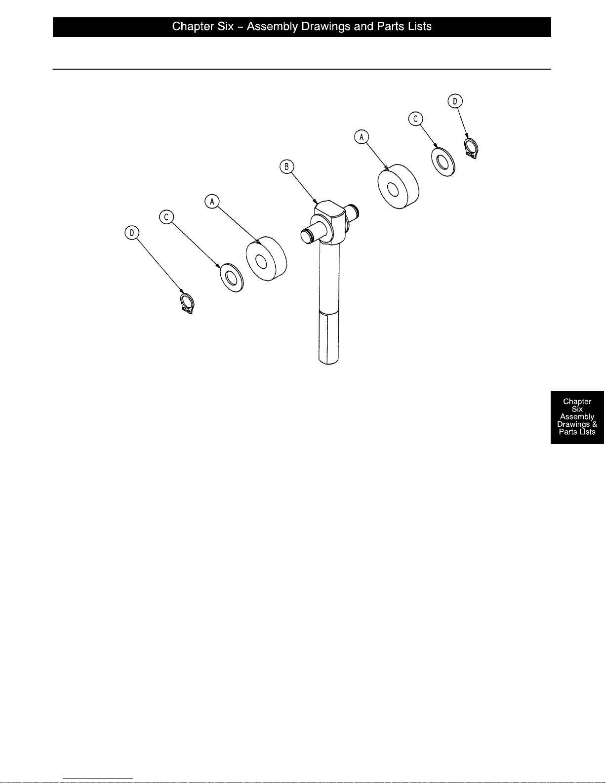
715–201–150 Brake Adjuster Assembly
Item Part No. Part Name Qty.
A 715–1–180 Cam Bearing 2
B 715–201–62 Threaded Stud Assembly 1
C14–4 Nylon Washer 4
D28–8 External Retaining Ring 2
page 6–11
Page 49
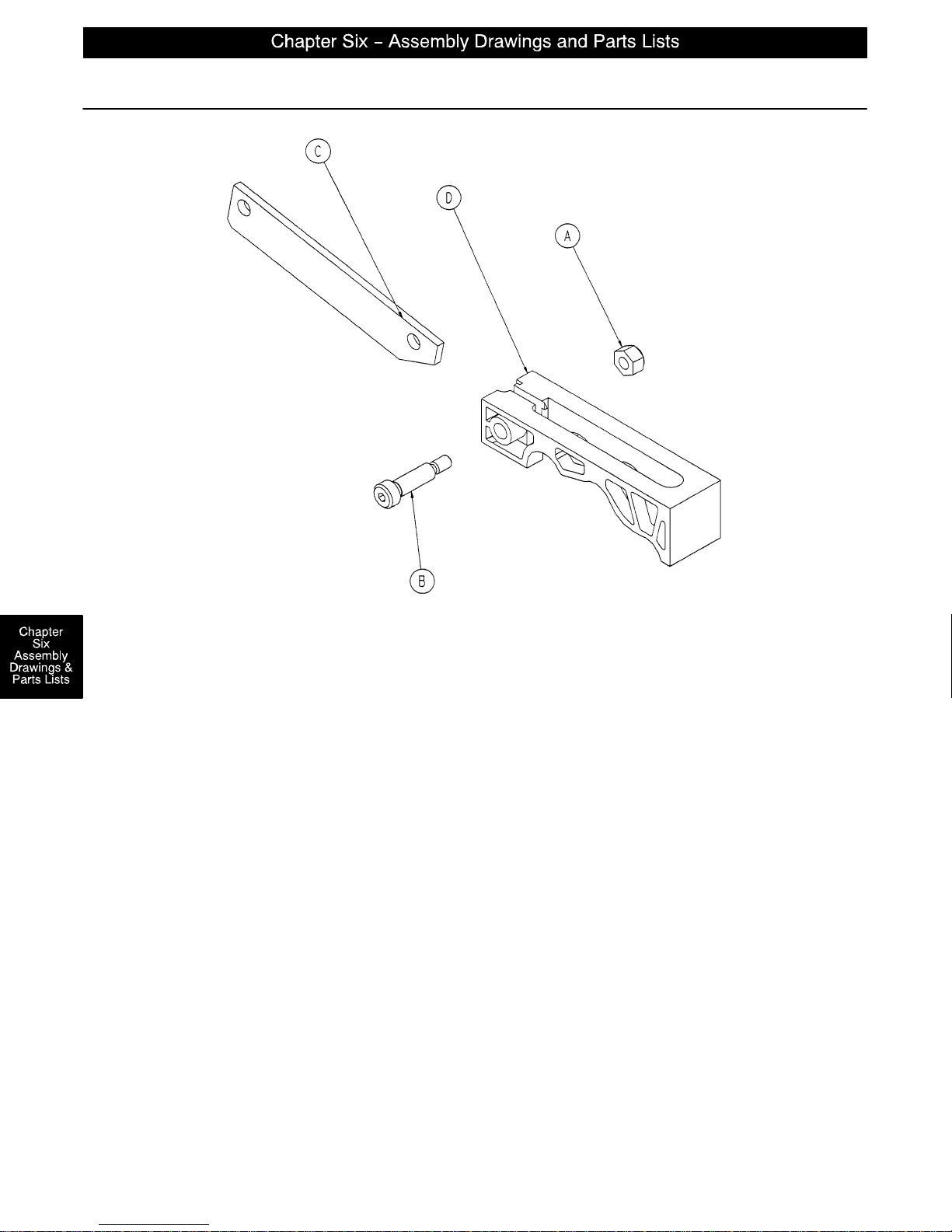
715–201–213 Brake Cam Assembly
Item Part No. Part Name Qty.
A16–59 Hex Nut 1
B8–21 Soc. Hd. Shoulder Screw 1
C 715–201–173 Brake Connecting Link 1
D 715–301–221 Brake Cam 1
page 6–12
Page 50
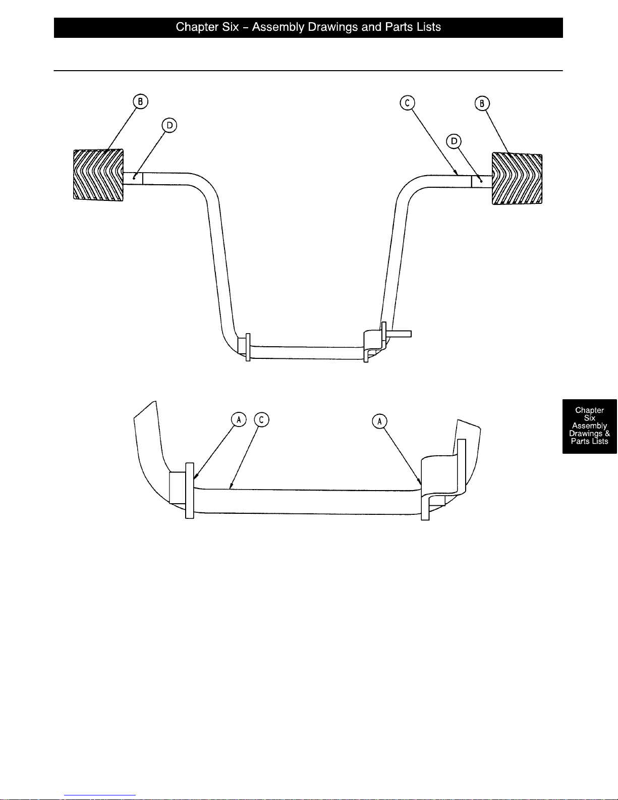
Side Control Pump Pedal Assembly
Item Part No. Part Name Qty.
A81–44 Bronze Bearing 2
B 715–201–126 Slip–On Pedal Pad 2
C 715–201–83 Pump Pedal Weldment 1
D26–143 Groove Pin 2
page 6–13
Page 51
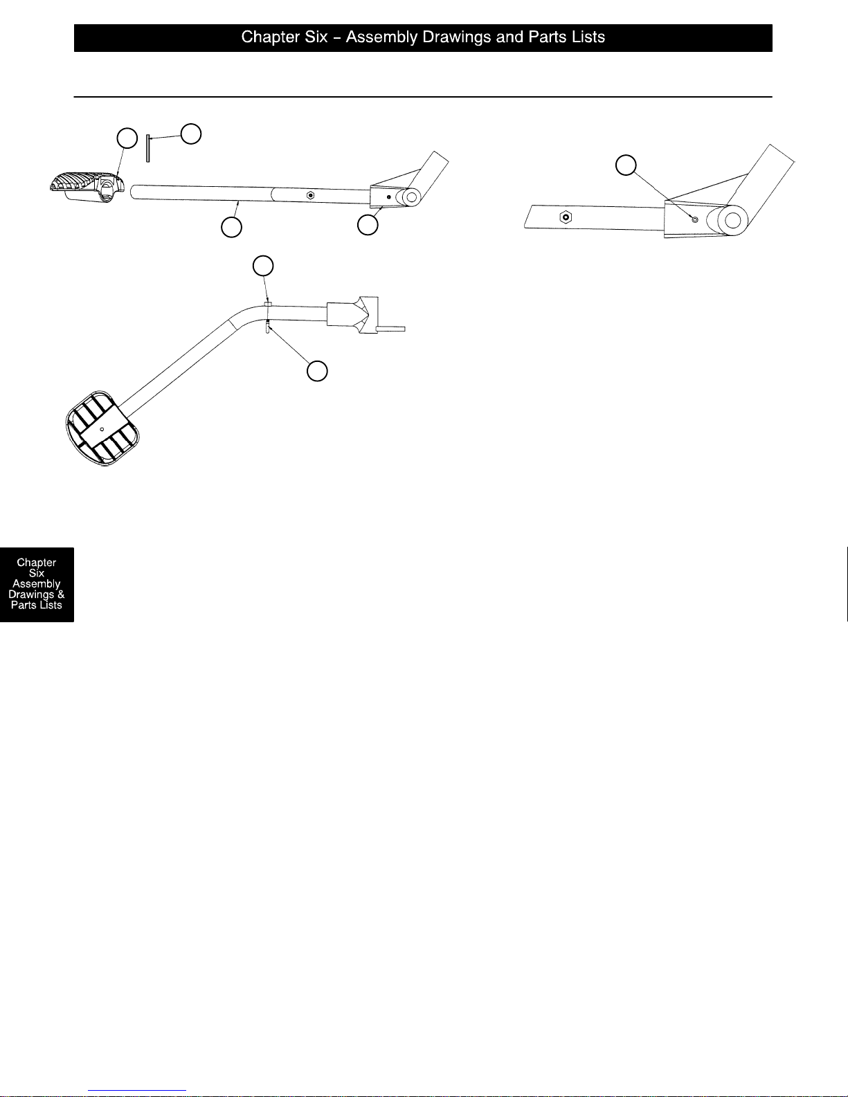
716–201–288 Foot End Pump Pedal Assembly
D
G
A
B
F
E
C
Item Part No. Part Name Qty.
A26–145 Spring Pin 1
B 716–201–14 Foot End Pump Rod 1
C 716–1–283 Pump Pivot Housing 1
D 715–201–126 Pedal 1
E 1210–201–551 Eye Bolt 1
F16–14 Nylock Nut 1
G26–261 Groove Pin 1
page 6–14
Page 52
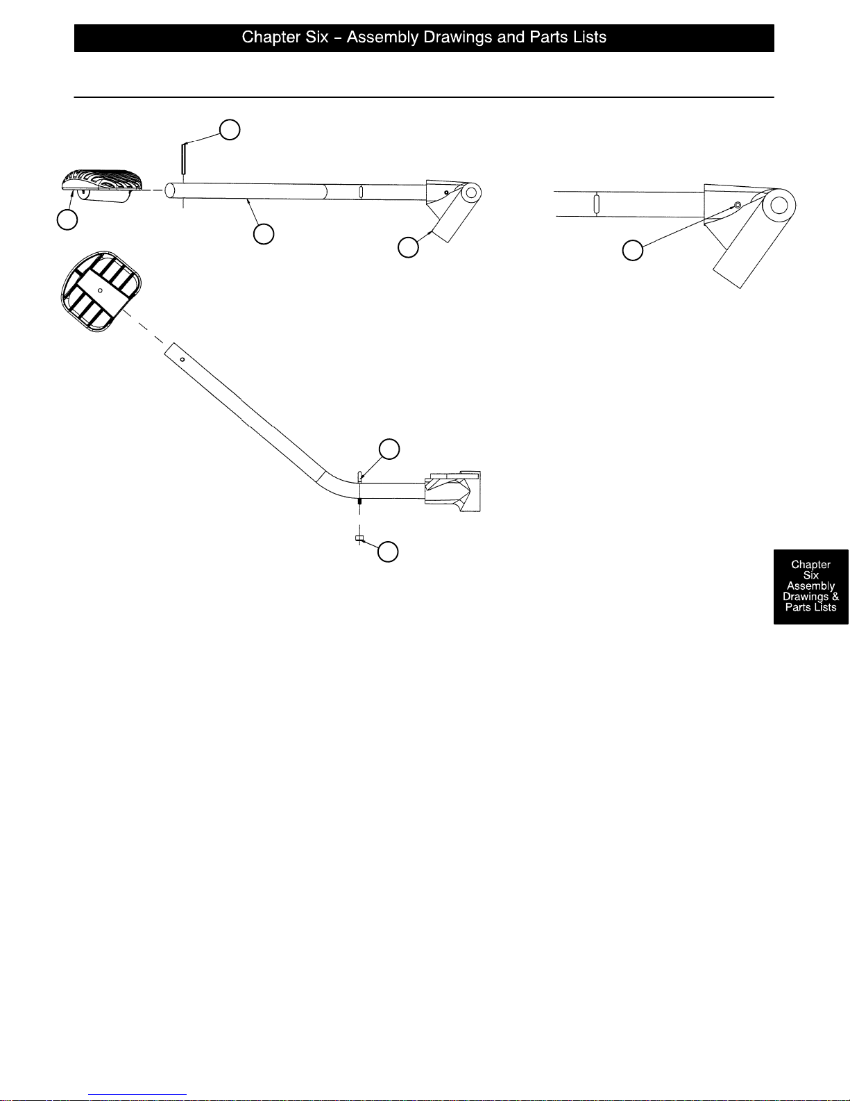
716–201–292 Head End Pump Pedal Assembly
G
D
C
B
E
A
F
Item Part No. Part Name Qty.
A26–145 Spring Pin 1
B 716–1–285 Pump Pivot Housing, Hd. End 1
C 716–201–14 Head End Pump Rod 1
D 715–201–126 Pedal 1
E 1210–201–551 Eye Bolt 1
F16–14 Nylock Nut 1
G26–261 Groove Pin 1
page 6–15
Page 53
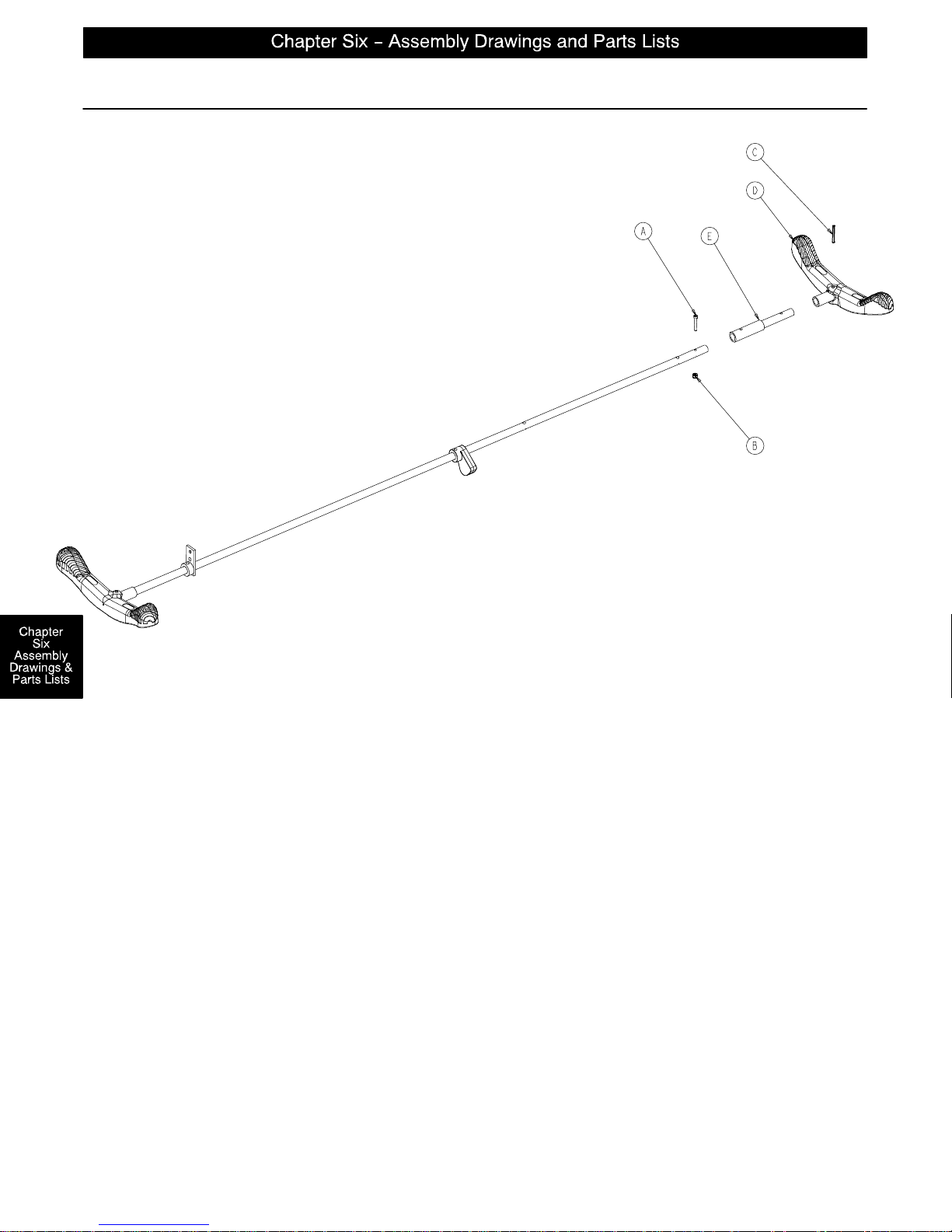
1069–70 Optional Removable Brake/Steer Pedal Assembly
Assembly part number 1069–70–10 (reference only)
Item Part No. Part Name Qty.
A4–160 Socket Hd. Cap Screw 1
B16–3 Fiberlock Nut 1
C26–143 Groove Pin 1
D 1210–201–153 Butterfly “V” Pedal 1
E 1068–300–000 Removable Pedal Adapter 1
page 6–15.1
Page 54
Notes
page 6–15.2
Page 55
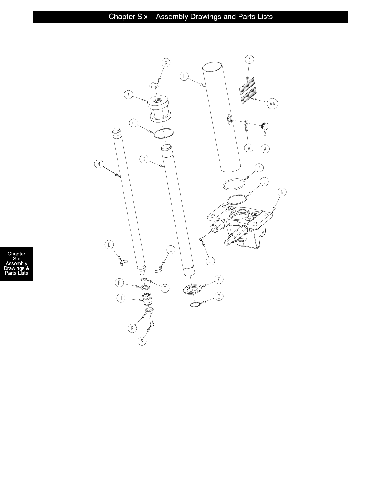
1231–70–10 Jack Assembly
Item Part No. Part Name Qty. Item Part No. Part Name Qty.
A 388–100–38 Plug 1 M 715–1–325 Actuator Rod 1
B 390–1–238 Actuator Gasket 1 N (page 6–17) Jack Base Ass’y1
C 390–1–243 Gasket 1 P 926–20–161 Parker Packing 1
D 390–1–244 Base Gasket 1 R 926–20–162 Wear Ring 1
E 390–2–139 Retaining Ring 2 S 4–14 Soc. Hd. Cap Screw 1
F 715–1–320 Jack Screen 1 T 45–14 O–Ring 1
G 715–1–323 Actuator Cylinder 1 W 45–110 O–Ring 1
H 715–1–331 Piston End 1 X 45–904 O–Ring 1
J 715–1–333 Rel. Rod Stop Sleeve 1 Y 45–978 O–Ring 1
K 715–1–340 Jack Cap Assembly 1 Z 1231–70–110 Label 1
L 715–1–422 Reservoir 1 AA 921–1–252 Serial Number Label 1
page 6–16
Page 56
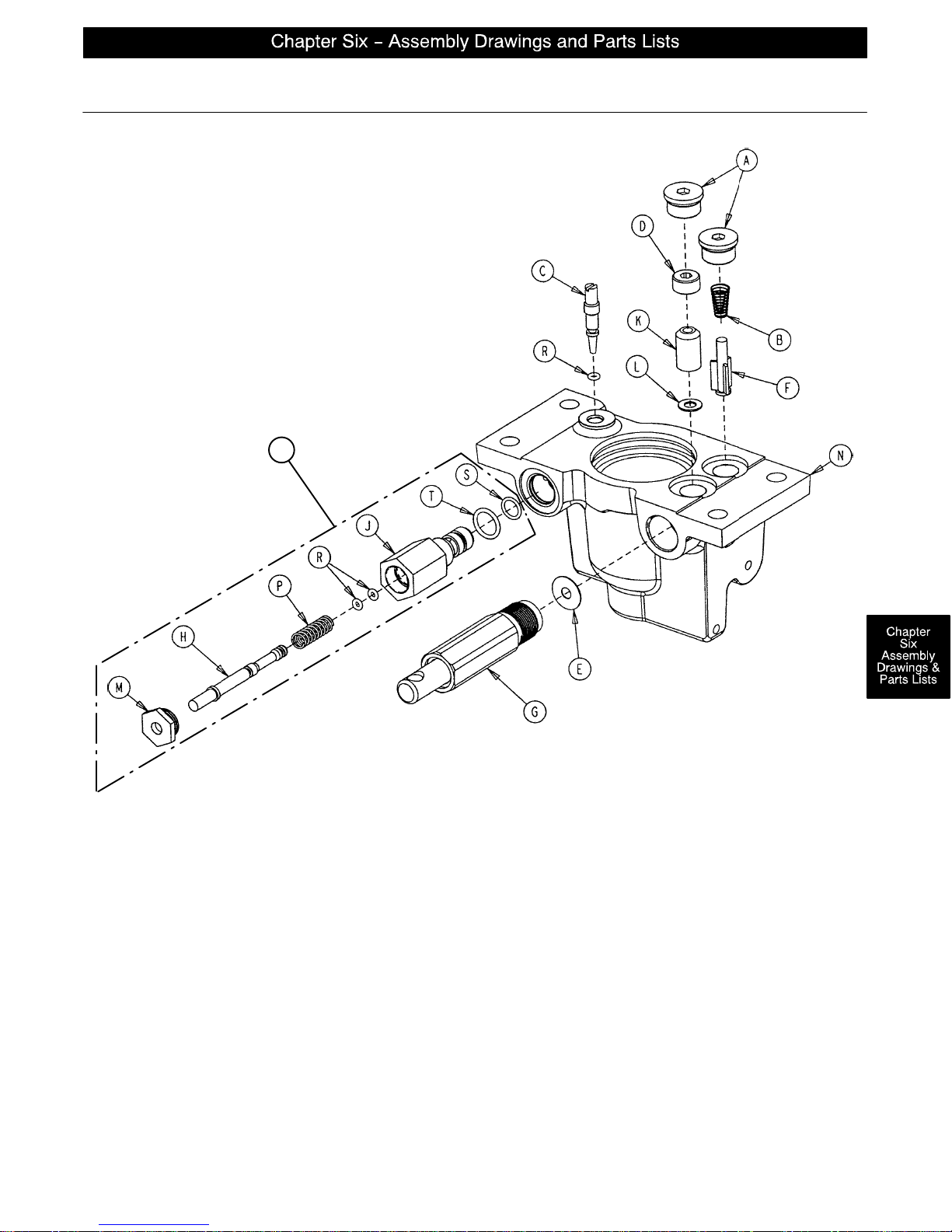
Jack Base Assembly
Assembly part number 1231–70–5 (reference only)
U
Item Part No. Part Name Qty. Item Part No. Part Name Qty.
A48–147 Base Plug 2 K 926–20–153 Check Valve 1
B 390–2–134 Conical Comp. Spring 1 L 926–20–154 Seal 1
C 715–1–307 Needle Valve 1 M 1210–170–13 Base Plug 1
D 715–1–309 Valve Plug 1 N 1210–270–12 Jack Base 1
E 715–1–329 Pump Seal 1 P 38–311 Compression Spring 1
F 715–1–341 Poppet 1 R 45–6O–Ring 3
G (page 6–20) Pump Piston Assembly 1 S 45–966 O–Ring 1
H 715–270–1 Pin 1 T 45–967 O–Ring 1
J 715–270–2 Pin Housing 1 U 715–270–100 Relief Valve Assembly 1
page 6–17
Page 57
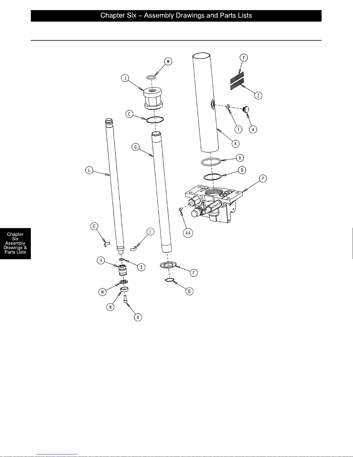
1231–70–210 Constant Flow Jack Assembly
Item Part No. Part Name Qty. Item Part No. Part Name Qty.
A 388–100–38 Plug 1 M 926–20–161 Parker Packing 1
B 390–1–238 Actuator Gasket 1 N 926–20–162 Wear Ring 1
C 390–1–243 Gasket 1 P (page 6–19) Jack Base Ass’y1
D 390–1–244 Base Gasket 1 R 4–14 Soc. Hd. Cap Screw 1
E 390–2–139 Retaining Ring 2 S 45–14 O–Ring 1
F 715–1–320 Jack Screen 1 T 45–110 O–Ring 1
G 715–1–323 Actuator Cylinder 1 W 45–904 O–Ring 1
H 715–1–331 Piston End 1 X 45–978 O–Ring 1
J 715–1–340 Jack Cap Assembly 1 Y 1231–70–211 Label 1
K 715–1–422 Reservoir 1 Z 921–1–252 Serial Number Label 1
L 715–1–325 Actuator Rod 1 AA 715–1–333 Rel. Rod Stop Sleeve 1
page 6–18
Page 58
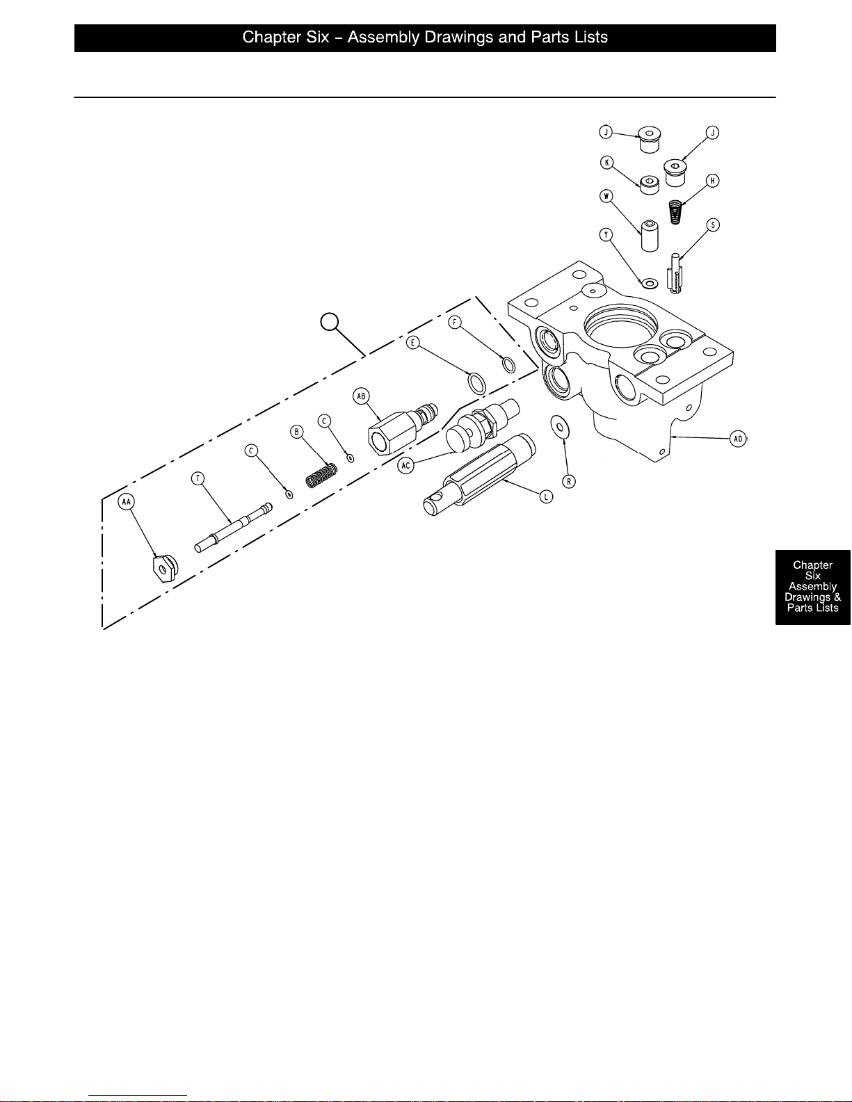
Constant Flow Jack Base Assembly
Assembly part number 5050–370–100 (reference only)
AE
Item Part No. Part Name Qty. Item Part No, Part Name Qty.
B38–311 Compression Spring 1 S 715–1–341 Poppet 1
C45–6O–Ring 2 T 715–270–1 Pin 1
E45–966 O–Ring 1 W 926–20–153 Check Valve 1
F45–967 O–Ring 1 Y 926–20–154 Seal 1
H 390–2–134 Conical Comp. Spring 1 AA 1210–170–13 Base Plug 1
J48–147 Base Plug 2 AB 2025–75–87 Pin Housing 1
K 715–1–309 Valve Plug 1 AC 5050–70–50 Adj. P.C. Valve Cartridge 1
L (page 6–20) Pump Piston Assembly 1 AD 5050–370–110 Jack Base 1
R 715–1–329 Pump Seal 1 AE 2025–700–26 Relief Valve Assembly 1
page 6–19
Page 59
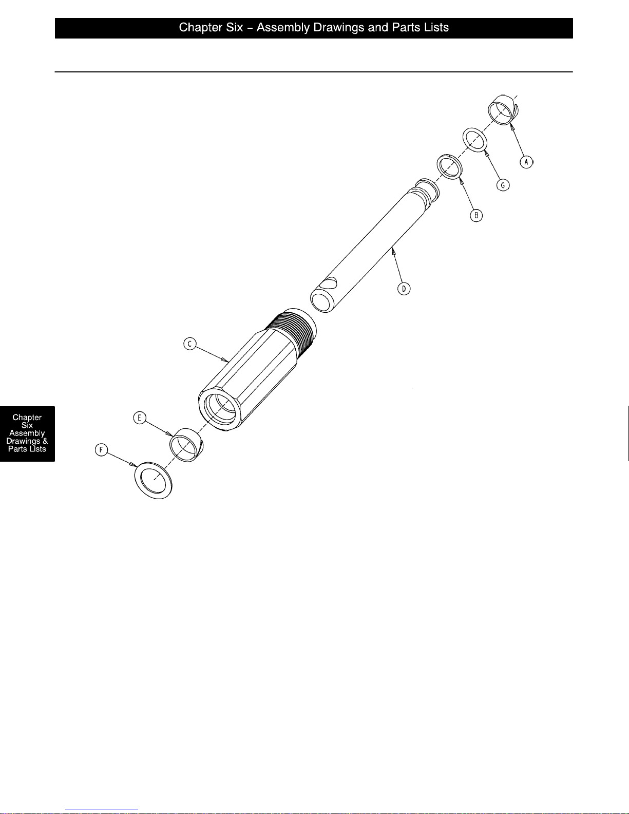
715–100–425 Jack Pump Piston Assembly
Assembly part number 715–201–325 (reference only)
Item Part No. Part Name Qty.
A 715–1–328 Piston Wear Ring 1
B 715–1–400 O–Ring Back Up 1
C 715–200–316 Pump Cylinder 1
D 715–201–318 Pump Piston 1
E 715–201–327 Cylinder Wear Ring 1
F14–50 Bearing Retainer 1
G45–110 O–Ring 1
page 6–20
715–1–329 Pump Seal (not shown) 1
Page 60
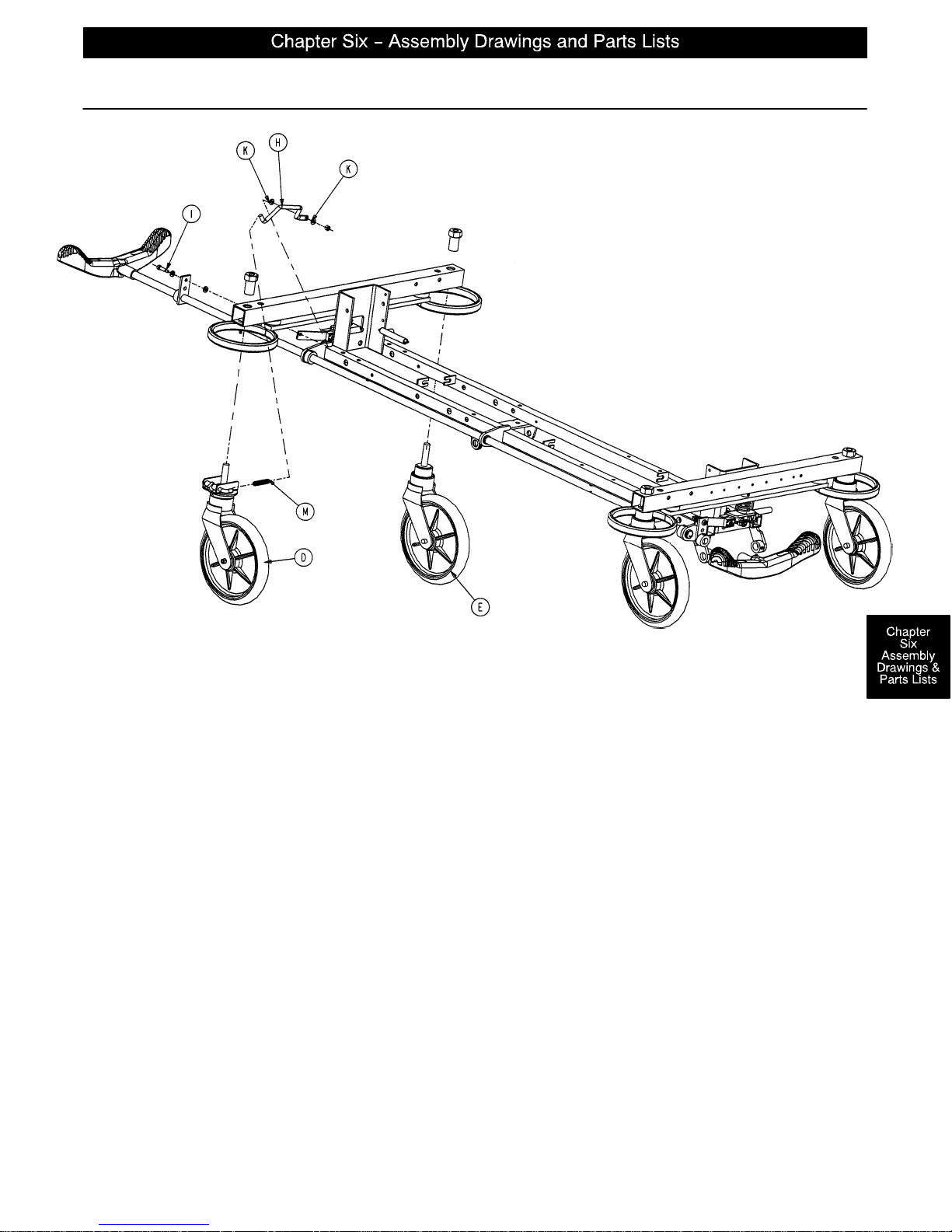
Base Assembly with Steerlock Caster Option
Assembly part number 1000–159
(reference only)
Item Part No. Part Name Qty.
D (page 6–22) Steer Caster Assembly 1
E (page 6–23) Caster Assembly 3
H 1000–210–62 Steer Lock Linkage Bar 1
I8–21 Shoulder Bolt 1
K14–2 Washer 2
M38–211 Spring 1
HEAD END
page 6–21
Page 61
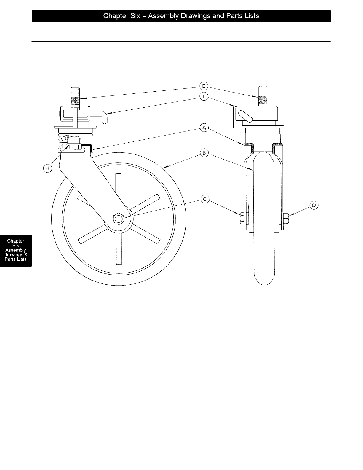
715–269–100 Caster Assembly with Steerlock
Assembly part number 715–2–21 (reference only)
Item Part No. Part Name Qty.
A 700–10–50 Steer Lock Caster Weldment 1
B 715–2–25 Caster Wheel 1
C16–60 Hex Nut 1
D3–99 Hex Bolt 1
E 715–3–96 Hex Bolt 1
F 1000–59–10 Latch Assembly 1
H11–310 Flat Washer 1
page 6–22
Page 62
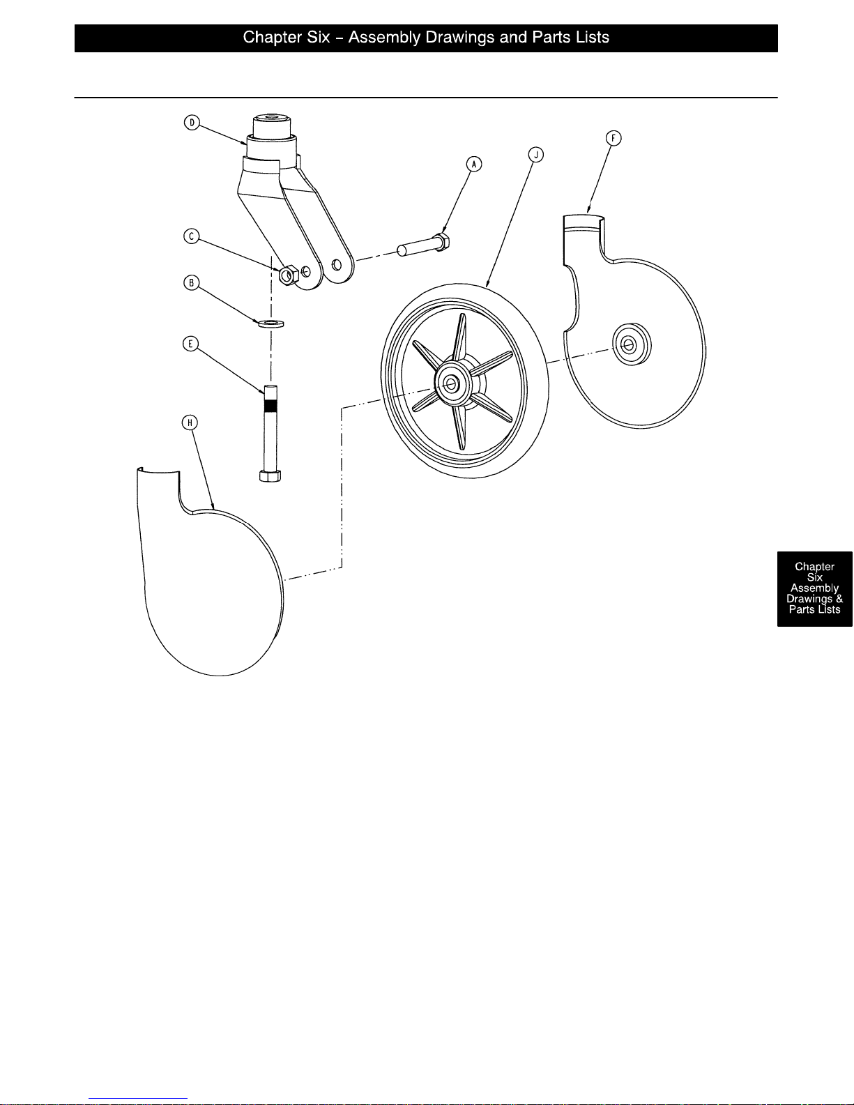
Standard Caster Assembly
Item Part No. Part Name Qty.
A3–99 Hex Hd. Cap Screw 1
B11–310 Washer 1
C16–60 Hex Nut 1
D 715–2–16 Horn Assembly 1
E 715–3–96 Hex Hd. Cap Screw 1
F 715–1–265 Wheel Cover, Right 1
H 715–1–266 Wheel Cover, Left 1
J 715–2–25 Wheel 1
p/n 715–259–400 – Kit to replace 4 standard caster assemblies with hardware – no caster covers.
p/n 715–269–400 – Kit to replace 3 standard caster assemblies and 1 steerlock caster with hardware – no
caster covers.
p/n 715–259–100 – Kit to replace 1 standard caster assembly with hardware – no caster covers.
p/n 1010–56–200 – Kit to replace both caster covers on all four wheels.
715–1–158 Caster Nut (not shown) 1
page 6–23
Page 63
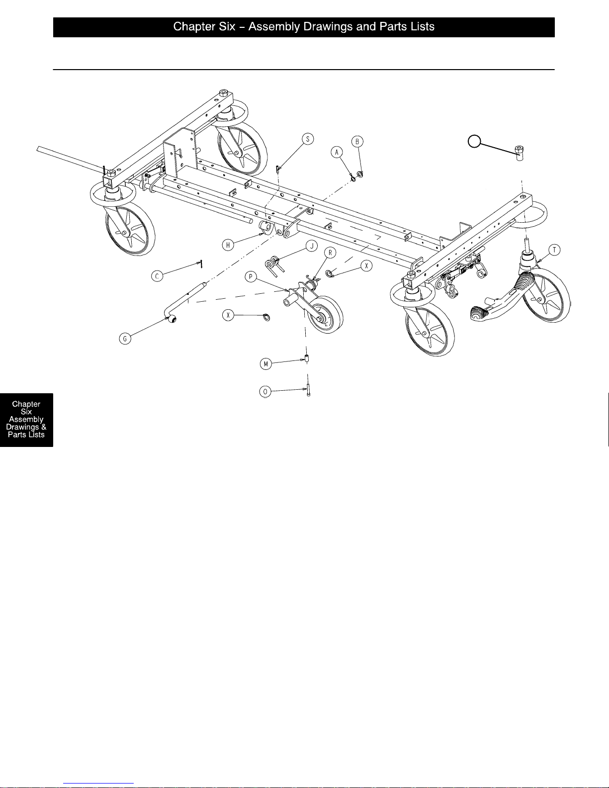
FOOT END
1010–260 Optional Fifth Wheel Assembly
U
Item Part No. Part Name Qty.
A14–79 Nylon Washer 1
B11–13 Washer 1
C27–16 Cotter Pin 1
G (page 6–25) Pivot Rod Assembly 1
H 1210–1–145 Cam 1
J 1210–1–148 Torsion Spring 1
M 1210–201–149 Spring Spacer 1
O4–10 Bolt 1
P (page 6–26) Wheel Arm Assembly 1
R 1210–1–146 Torsion Spring 1
S26–35 Roll Pin 1
T (page 6–23) Caster Assembly 4
U 715–1–158 Caster Nut 4
X14–80 Nylon Washer 2
HEAD END
page 6–24
Page 64
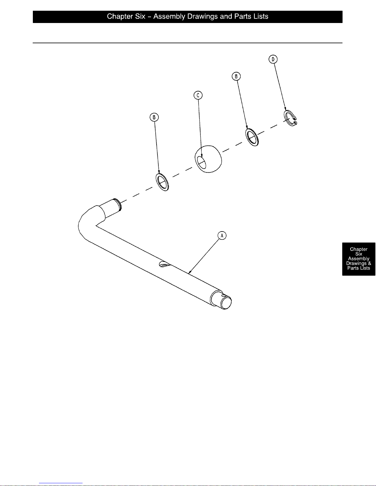
Fifth Wheel Pivot Rod Assembly
Assembly part number 1210–201–2
(reference only)
Item Part No. Part Name Qty.
A 1210–1–143 Pivot Rod 1
B14–79 Nylon Washer 2
C 1210–1–144 Roller 1
D28–131 Snap Ring 1
E27–16 Cotter Pin 1
page 6–25
Page 65
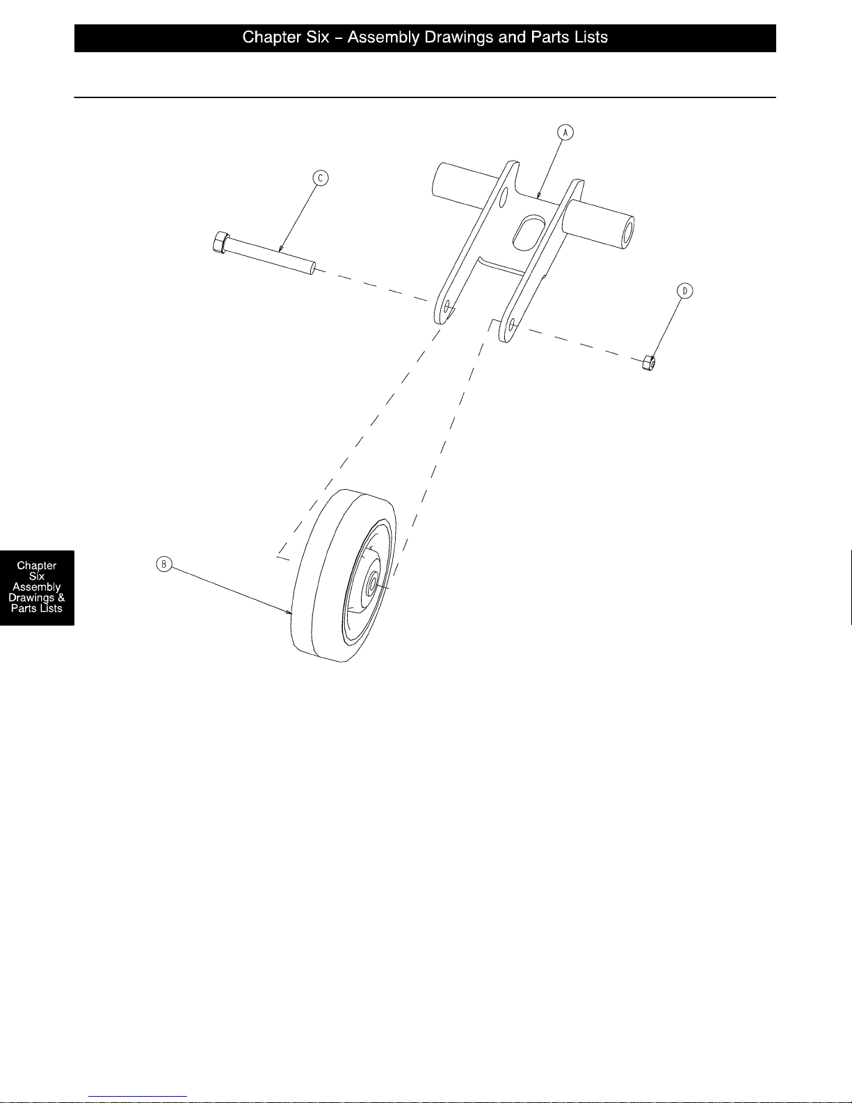
715–201–125 Fifth Wheel Arm Assembly
Item Part No. Part Name Qty.
A 1210–201–553 Wheel Arm 1
B 1210–1–147 Fifth Wheel 1
C 3–31 Hex Hd. Cap Screw 1
D 16–35 Nylock Nut 1
page 6–26
Page 66

page 6–27
Page 67
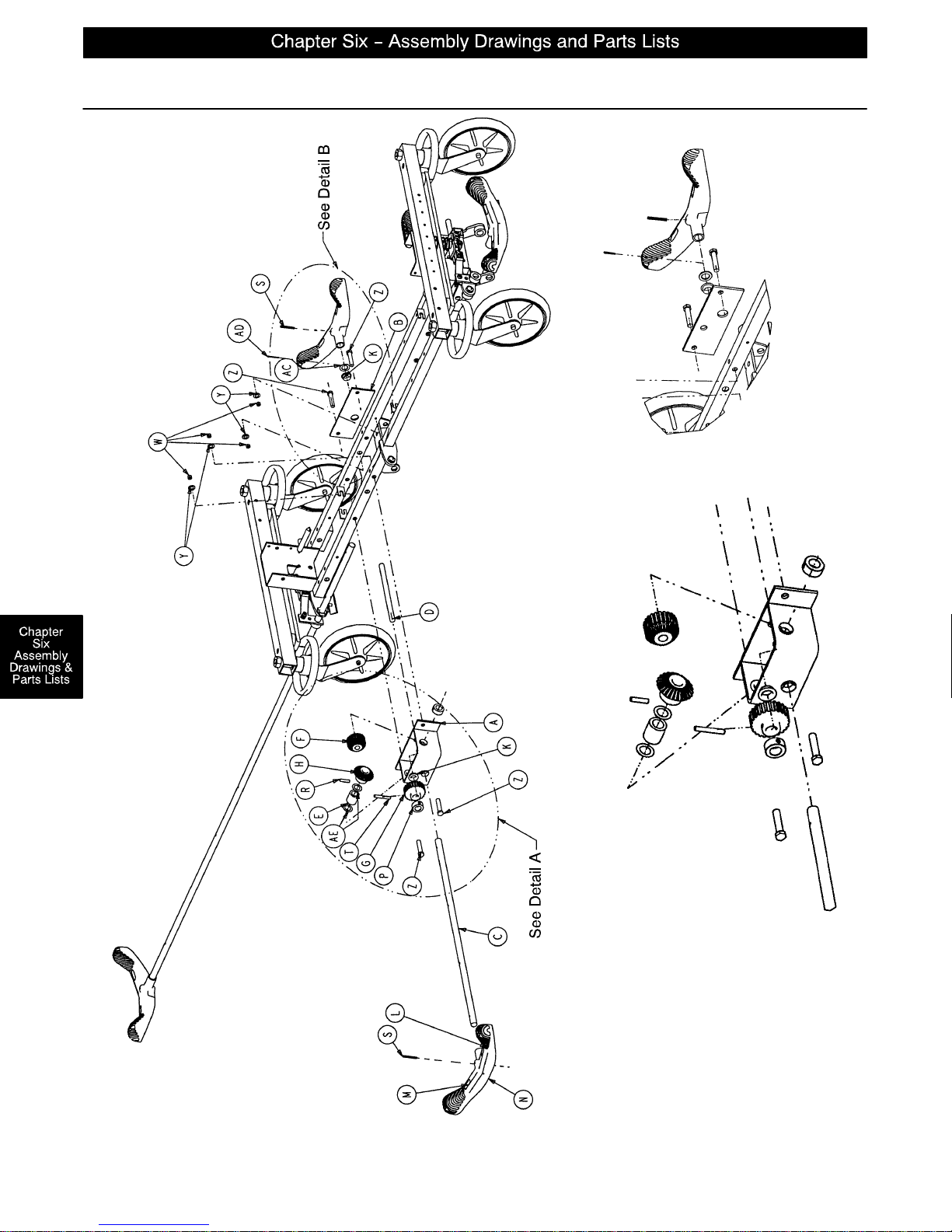
Optional Side Control Brake Assembly
DETAIL B
FOOT END
Assembly part number 1001–400 (reference only)
DETAIL A
page 6–28
Page 68
Optional Side Control Brake Assembly
Item Part No. Part Name Qty.
A 1210–301–400 Gear Box Weldment 1
B 1210–301–412 Support 1
C 1210–201–409 Side Control Brake/Steer Rod 1
D 1210–201–407 Pin 1
E 1210–301–406 Spacer 1
F 1210–301–405 Miter/Spur Gear 1
G 1210–301–404 Spur Gear 1
H 1210–301–403 Miter Gear 1
K 1210–201–401 Flange Bearing 5
L 1210–201–336 Steer Label 2
M 1210–201–335 Brake Label 2
N 1210–201–153 Butterfly “V” Pedal 2
P42–20 Collar 1
R26–265 Gear Dowel Pin 1
S26–143 Pedal Dowel Pin 2
T26–166 Groove Pin 1
W16–35 Lock Nut 4
Y11–4 Flat Washer 4
Z3–45 Hex Hd. Cap Screw 4
AA 1210–201–341 Brake/Steer Label, Right* 1
AB 1210–201–342 Brake/Steer Label, Left* 1
AC 14–71 Washer 1
AD 27–16 Cotter Pin 1
AE 14–80 Washer 2
* Reference hood/label assembly drawing (page 6–32) for label positioning.
page 6–29
Page 69
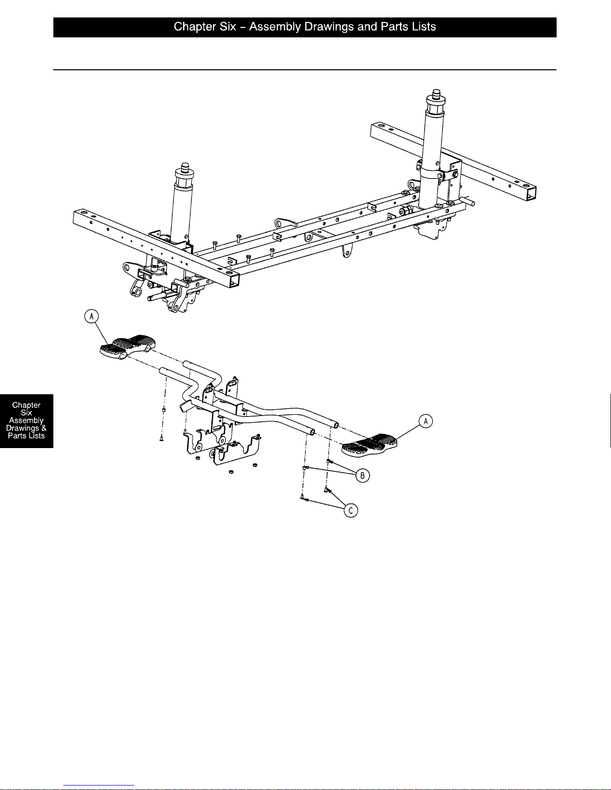
Optional Uni–Lower Pedal Assembly
Assembly part number 1210–500 (reference only)
HEAD END
FOOT END
Item Part No. Part Name Qty.
A 715–201–127 Uni–Lowering Pedal 2
B 715–1–333 Release Rod Stop Sleeve 4
C25–50 Pop Rivet 4
page 6–30
Page 70
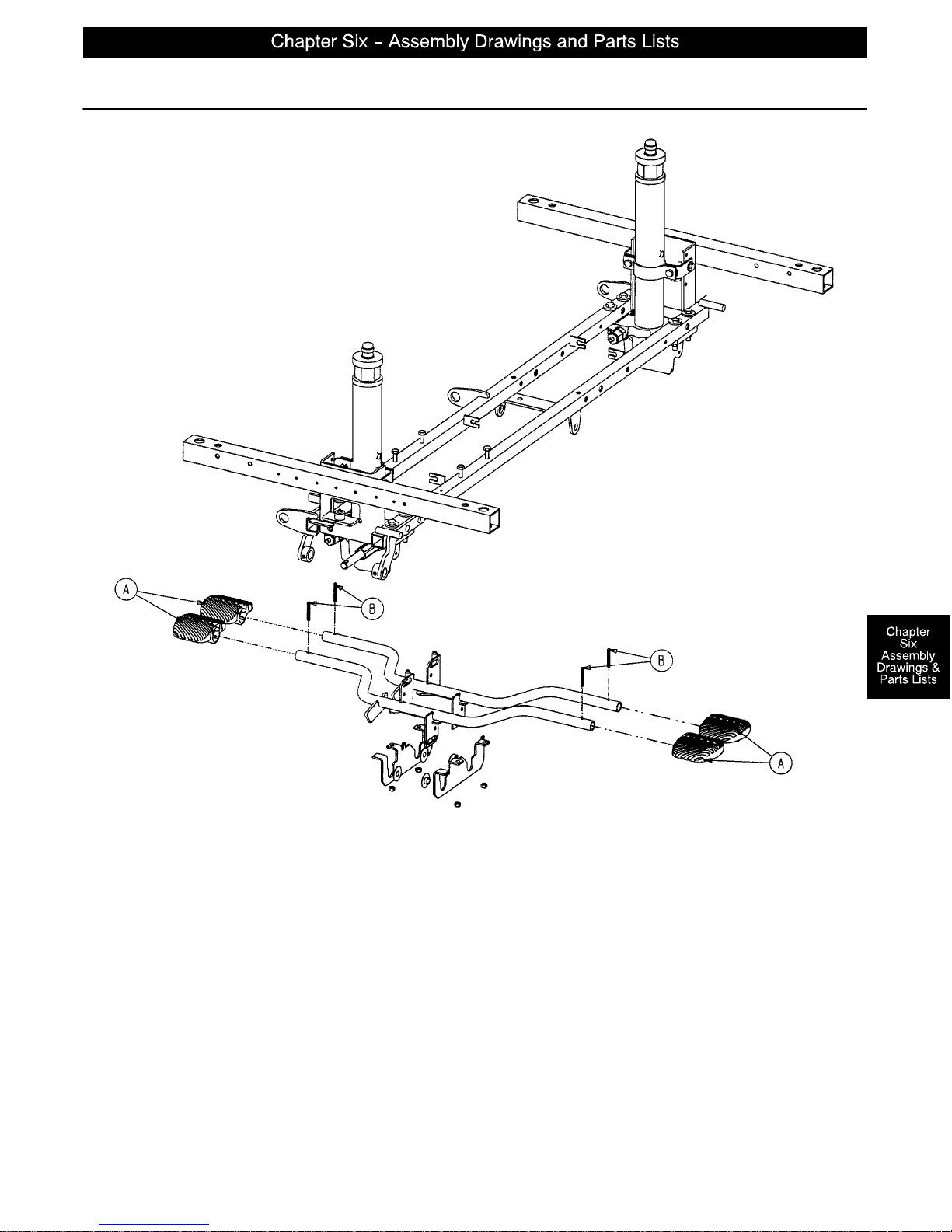
Optional Dual Lowering Pedal Assembly
Assembly part number 1210–501 (reference only)
HEAD END
FOOT END
Item Part No. Part Name Qty.
A 715–201–126 Pump Pedal 4
B26–143 Groove Pin 4
page 6–31
Page 71
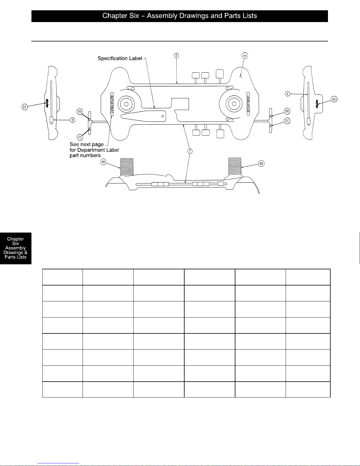
Side Control Base Labeling Assembly
Color
Set P/N
RED
1068–702–210
PURPLE
1068–702–220
GREEN
1068–702–230
GRAY
1068–702–240
TEAL
1068–702–250
PINK
1068–702–260
BLUE
1068–702–270
Item Part No. Part Name Qty.
AA 1001–200–2 Base Hood 1
BB 715–1–134 Bellows 2
CC 1210–201–335 Red Brake Label 2
DD 1210–201–336 Green Steer Label 2
EE 946–201–60 Stryker Logo Label 2
Item A Control
Label, Head End
1001–700–113 1001–700–114 1068–702–211 1068–702–212 1010–700–15
1001–700–123 1001–700–124 1068–702–221 1068–702–222 1010–700–25
1001–700–133 1001–700–134 1068–702–231 1068–702–232 1010–700–35
1001–700–143 1001–700–144 1068–702–241 1068–702–242 1010–700–45
1001–700–153 1001–700–154 1068–702–251 1068–702–252 1010–700–55
1001–700–163 1001–700–164 1068–702–261 1068–702–262 1010–700–65
1001–700–173 1001–700–174 1068–702–271 1068–702–272 1010–700–75
Item B Control
Label, Foot End
Item C Control
Label, Right
Item D Control
Label, Left
Litter Bumper
Strip
page 6–32
Page 72
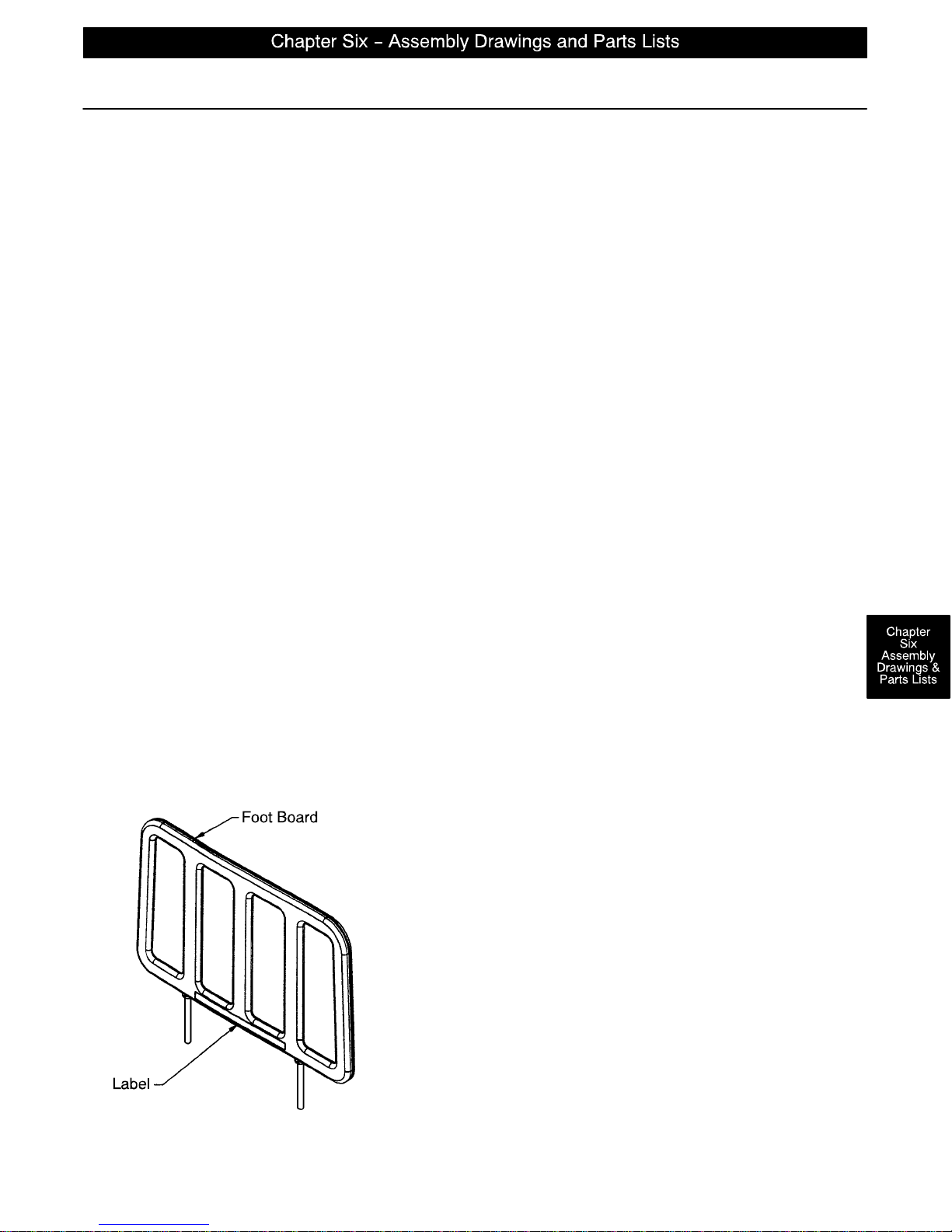
Department Labels
BASE HOOD DEPARTMENT LABELS
Department Label Part Number
Emergency 1010–900–215
PACU 1010–900–220
Transport 1010–900–225
Surgery 1010–900–230
Extended Stay 1010–900–235
Maternity 1010–900–240
Endoscopy 1010–900–245
Radiology 1010–900–250
Nuclear Medicine 1010–900–255
Ambulatory Surgery 1010–900–260
G.I. Lab 1010–900–265
Cath. Lab 1010–900–270
Same Day Surgery 1010–900–275
Cardio. 1010–900–280
Ultrasound 1010–900–285
NOTE
All base hood department labels are quantity of two.
FOOT BOARD DEPARTMENT LABELS
Department Label Part No.
Demo Stryker 1010–900–186
Ophthalmology 1010–900–187
Outpatient Surgery 1010–900–188
Recovery 1010–900–189
Trauma 1010–900–190
Urgence 1010–900–191
Special (Blank) 1010–900–192
page 6–33
Page 73
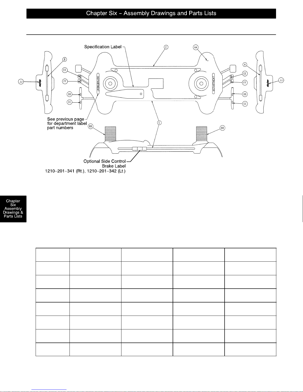
End Control Base Labeling Assembly
Color
Set P/N
RED
1001–800–110
PURPLE
1001–800–120
GREEN
1001–800–130
GRAY
1001–800–140
TEAL
1001–800–150
PINK
1001–800–160
BLUE
1001–800–170
Item Part No. Part Name Qty.
AA 1001–200–1 Hood 1
BB 715–1–134 Bellows 2
CC 1210–201–335 Red Brake Label 2
DD 1210–201–336 Green Steer Label 2
EE 1210–201–337 Head Down Label, Foot End 2
FF 1210–201–338 Foot Down Label, Foot End 2
JJ 946–201–6 Stryker Logo Label 2
Item A Control
Label, Head End
1001–800–111 1001–800–112 1001–800–13 1010–700–15
1001–800–121 1001–800–122 1001–800–23 1010–700–25
1001–800–131 1001–800–132 1001–800–33 1010–700–35
1001–800–141 1001–800–142 1001–800–43 1010–700–45
1001–800–151 1001–800–152 1001–800–53 1010–700–55
1001–800–161 1001–800–162 1001–800–63 1010–700–65
1001–800–171 1001–800–172 1001–800–73 1010–700–75
Item B Control
Label, Foot End
Item C Side Control
Label
Litter Bumper Strip
page 6–34
Page 74
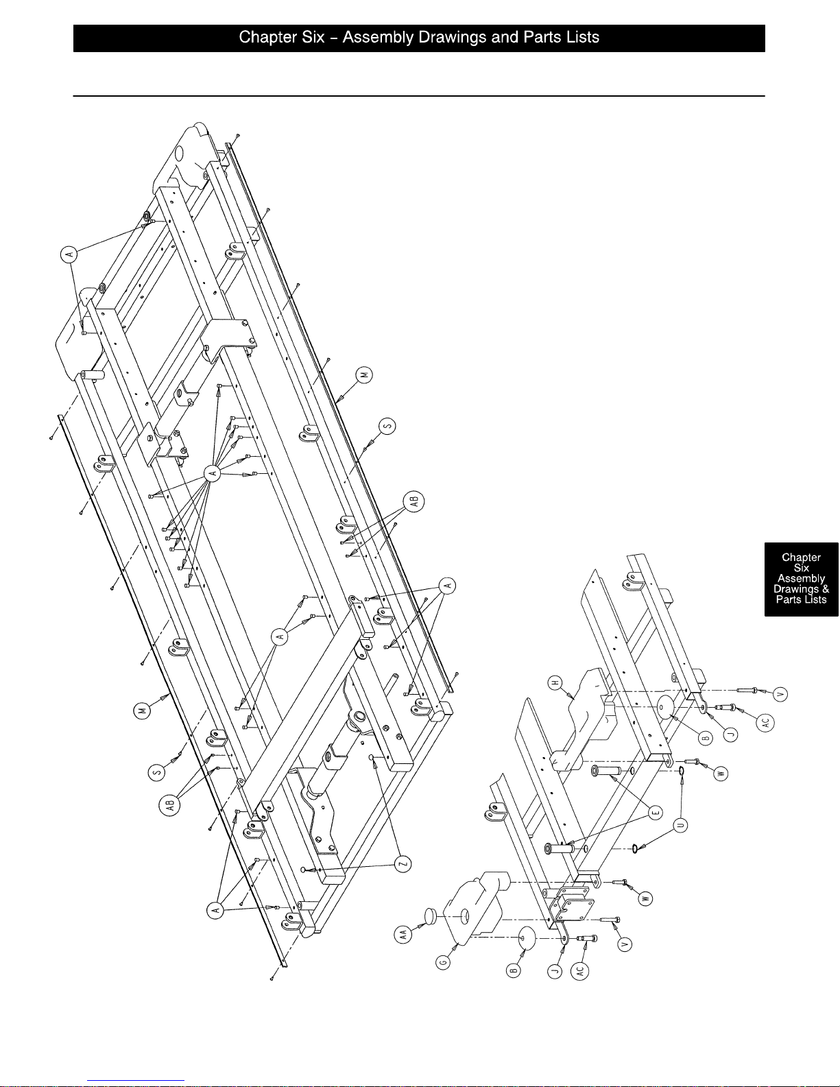
FOOT END
Litter Assembly
Assembly part number 1069–30–10 (reference only)
page 6–35
Page 75
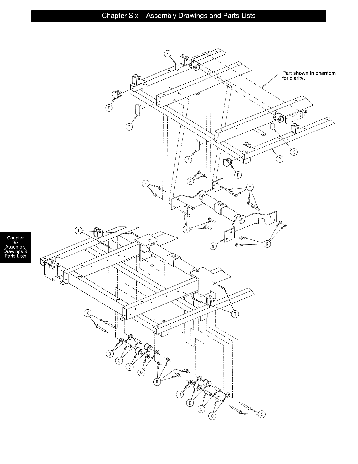
Litter Assembly
HEAD END
page 6–36
Page 76
Litter Assembly
Item Part No. Part Name Qty.
A 721–31–65 Hole Plug 24
B 721–32–49 Bumper Roller 2
C 721–32–107 Roller Sleeve 4
D 721–32–108 Support Roller 4
E 721–40–26 Foot Board Receptacle 2
F 1001–30–29 End Plug 2
G 1010–1–13 Foot Cover, Right 1
H 1010–1–14 Foot Cover, Left 1
J 1010–1–17 Roller Plate 2
K 1010–32–66 Rectangular Hole Plug 2
L (page 6–38) Foot End Jack Support Ass’y1
M 1068–20–38 Bumper Channel 2
N (page 6–39) Head End Jack Support Ass’y1
P 1069–30–50 Litter Frame Weldment 1
Q11–14 Washer 8
R16–28 Hex Nut 12
S25–38 Blind Rivet 16
T26–57 Spring Pin 4
U28–23 External Retaining Ring 2
V3–47 Hex Cap Screw 10
W3–54 Hex Cap Screw 2
X3–76 Hex Cap Screw 4
Y37–49 Rectangular Hole Plug 2
Z37–52 Rubber Bumper 2
AA 37–59 Hole Plug 1
AB 37–74 Hole Plug 4
AC 8–24 Soc. Hd. Shoulder Screw 2
page 6–37
Page 77
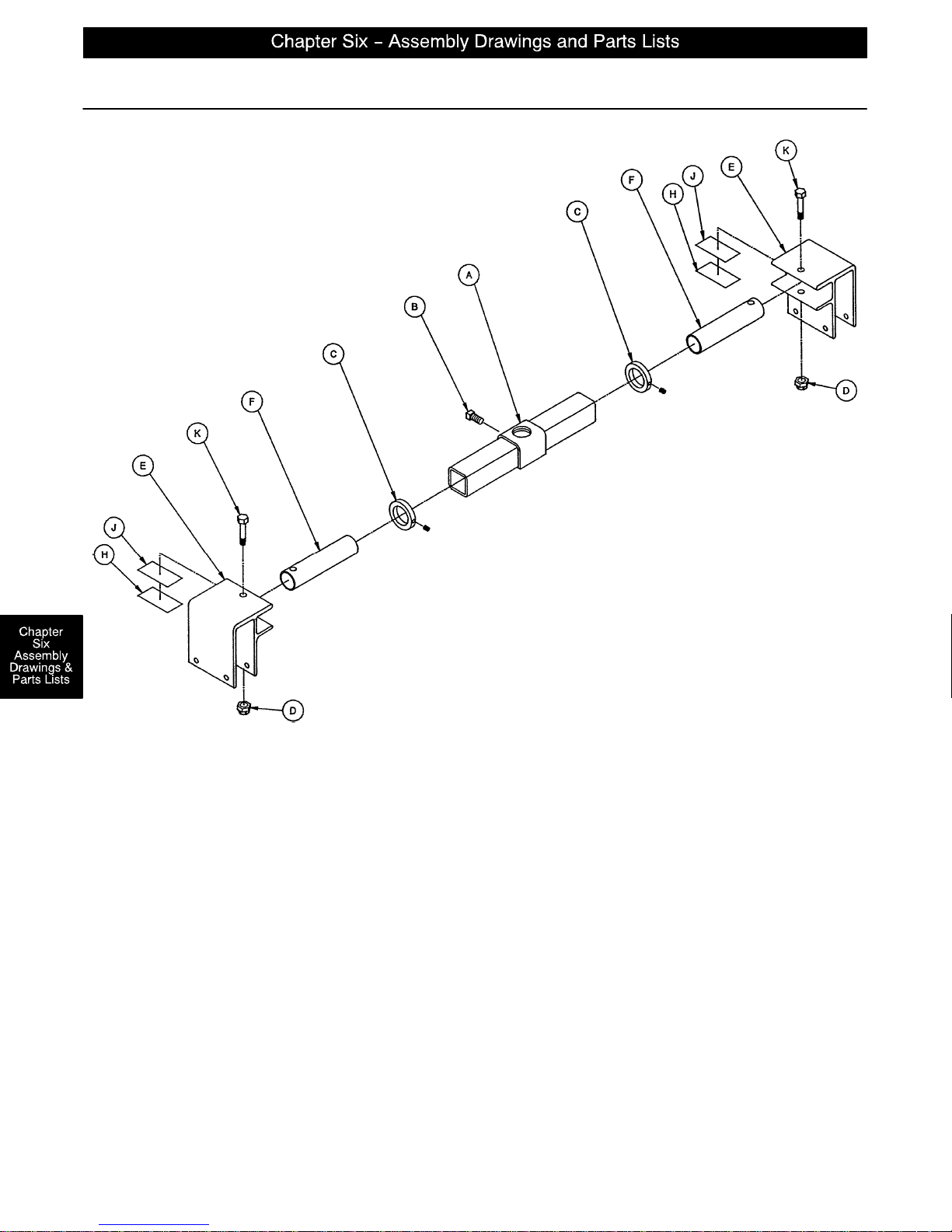
Foot End Jack Support Assembly
Assembly part number 1010–32–110 (reference only)
Item Part No. Part Name Qty.
A 1010–32–85 Support Tube Assembly 1
B46–1 Sq. Hd. Set Screw 1
C 938–1–401 Collar Assembly 2
D16–11 Flexlock Nut 2
E 1010–32–108 Roller Assembly 2
F 1010–32–64 Carrier Tube, Std. 2
H 919–30–28 Rack Guide 2
J44–29 Double–Sided Foam Tape 6”
K3–40 Hex Hd. Cap Screw 2
page 6–38
Page 78
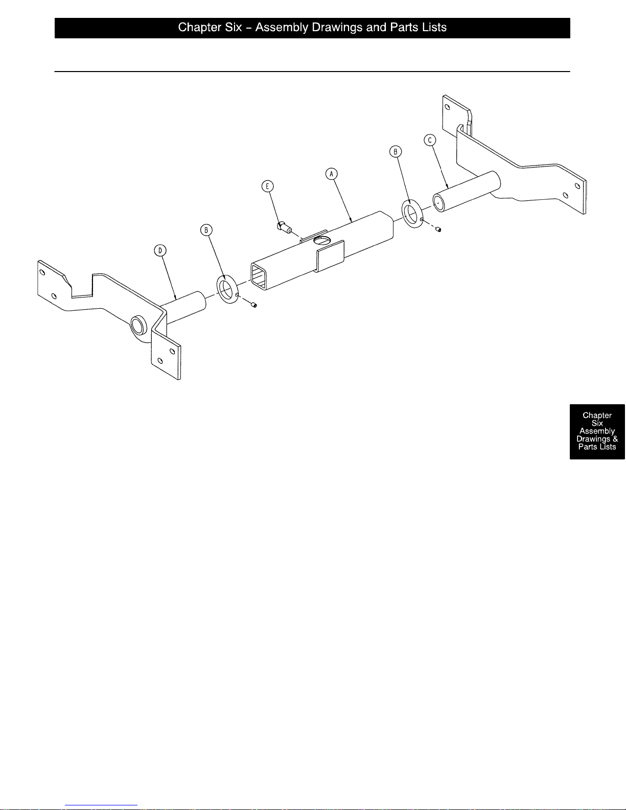
Head End Jack Support Assembly
Assembly part number 1069–30–30 (reference only)
Item Part No. Part Name Qty.
A 721–32–160 Support Tube Assembly 1
B 938–1–401 Collar 2
C 1069–30–20 Jack Mount Weldment, Left 1
D 1069–30–25 Jack Mount Weldment, Right 1
E46–1 Sq. Hd. Set Screw 1
page 6–39
Page 79
page 6–40
Page 80
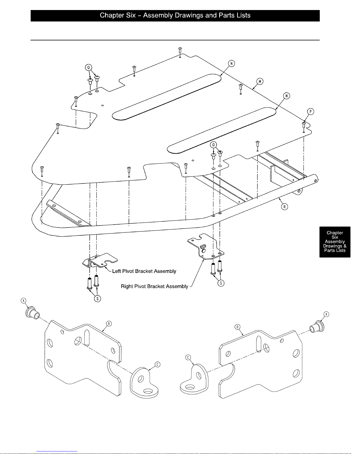
1069–32–20 Zero Articulating Pneumatic Fowler Assembly
LEFT PIVOT BRACKET ASSEMBLY RIGHT PIVOT BRACKET ASSEMBLY
page 6–41
Page 81
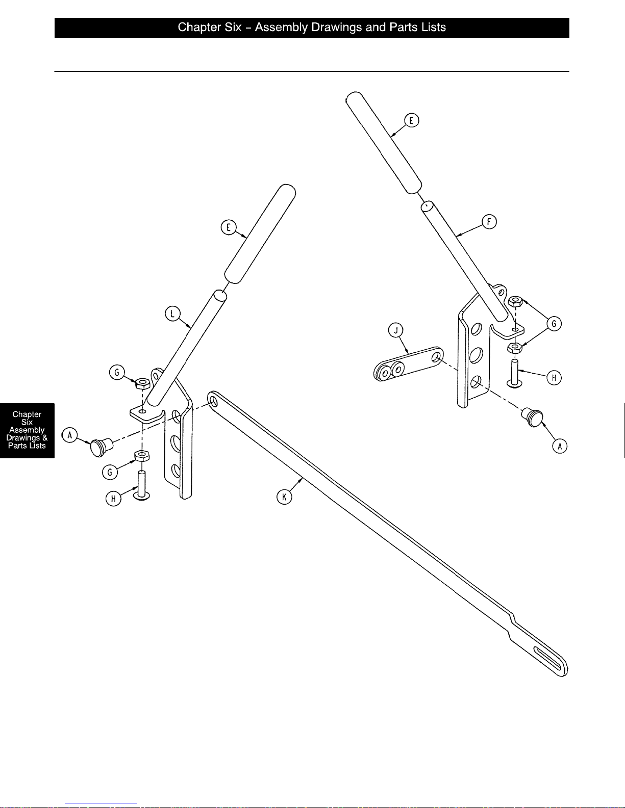
1069–32–20 Zero Articulating Pneumatic Fowler Assembly
Left Handle Sub–assembly
Right Handle Sub–assembly
page 6–42
Page 82
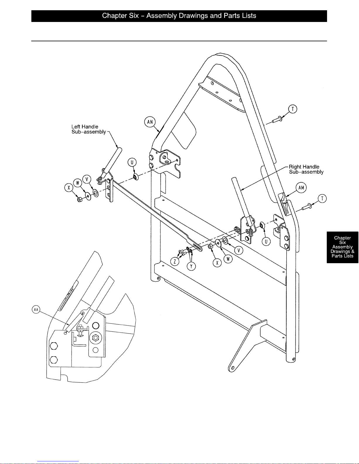
1069–32–20 Zero Articulating Pneumatic Fowler Assembly
Spring Attachment – Both Sides
page 6–43
Page 83
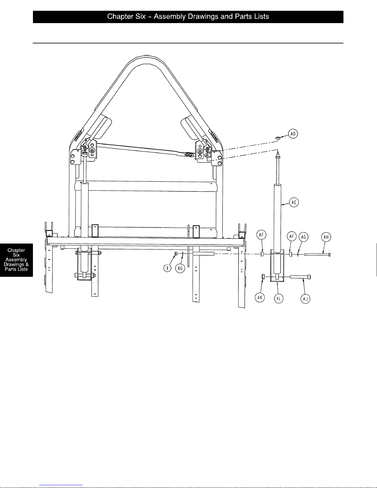
1069–32–20 Zero Articulating Pneumatic Fowler Assembly
Cylinder Assembly – Both Sides
page 6–44
Page 84
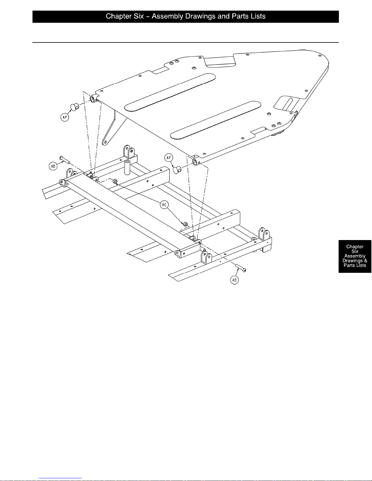
1069–32–20 Zero Articulating Pneumatic Fowler Assembly
Item Part No. Part Name Qty. Item Part No. Part Name Qty.
A 1069–31–11 Rivet 4 V 14–87 Nylon Flat Washer 2
B 1069–31–41 Handle Pivot Bracket, Lt. 1 W 1 1–180 Steel Flat Washer 2
C 1210–31–103 “L” Bracket 2 X 16–28 Nylock Nut 4
D 1069–31–46 Handle Pivot Bracket, Rt. 1 Y 13–18 Ext. Tooth Lock Washer 2
E 1069–31–200 Red Handle Cover 2 Z 7–19 Truss Hd. Screw 2
F 1069–31–85 Handle Weldment, Rt. 1 AA 38–436 Extension Spring 2
G15–3 Jam Nut 4 AB 4–54 Button Hd. Screw 2
H7–50 Truss Hd. Screw 2 AC 16–11 Nylock Nut 2
J 1069–31–31 Handle Adj. Link, Short 1 AD 15–59 M10 Nut 2
K 1069–31–32 Handle Adj. Link, Long 1 AE 360–31–77 Pneumatic Cylinder 2
L 1069–31–80 Handle Weldment, Lt. 1 AF 52–86 Nyliner 4
M 1069–32–65 Fowler Skin 1 AG 11–63 Flat Washer 4
N 7900–1–102 Velcro Pile 2 AH 3–37 Hex Hd. Cap Screw 2
P25–50 Pop Rivet 10 AJ 4–323 M10 Soc. Hd. Cap Scr. 2
Q7–42 Truss Hd. Screw 4 AK 16–90 M10 Nylock Nut 2
R 1069–32–60 Fowler Weldment 1 AL 1069–31–36 Cylinder Mounting Box 2
S 1069–31–12 Barrel Nut 4 AM 1069–60–91 Fowler Rel. Label, Rt. 1
T7–62 Truss Hd. Screw 2 AN 1069–60–92 Fowler Rel. Label, Lt. 1
U 3001–300–99 Fowler Pivot Bushing 2 AP 1069–31–13 Hole Plug 2
page 6–45
Page 85
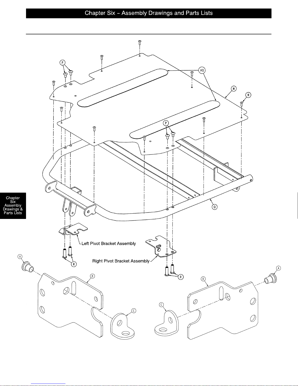
1069–32–15 Optional Single Articulating Pneumatic Fowler Ass’y
LEFT PIVOT BRACKET ASSEMBLY RIGHT PIVOT BRACKET ASSEMBLY
page 6–46
Page 86
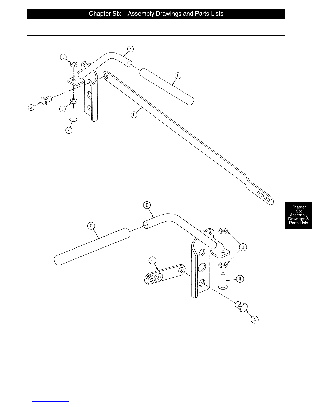
1069–32–15 Optional Single Articulating Pneumatic Fowler Ass’y
Left Handle Assembly
Right Handle Assembly
page 6–47
Page 87
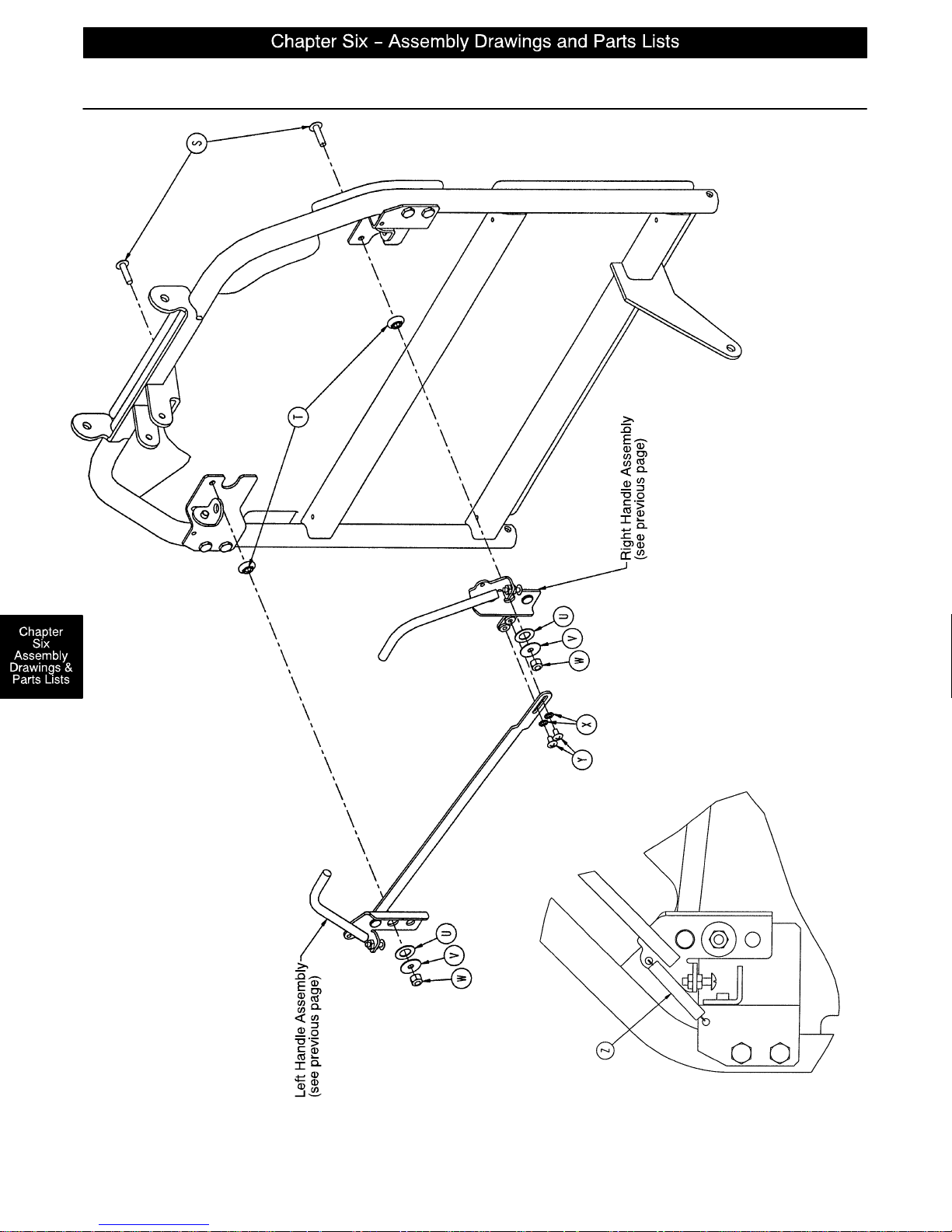
1069–32–15 Optional Single Articulating Pneumatic Fowler Ass’y
page 6–48
BOTH SIDES
SPRING A TT ACHMENT
Page 88
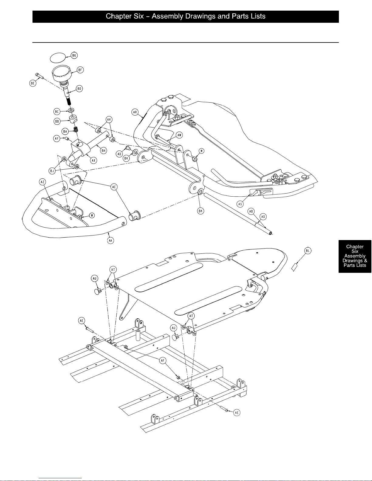
1069–32–15 Optional Single Articulating Pneumatic Fowler Ass’y
page 6–49
Page 89
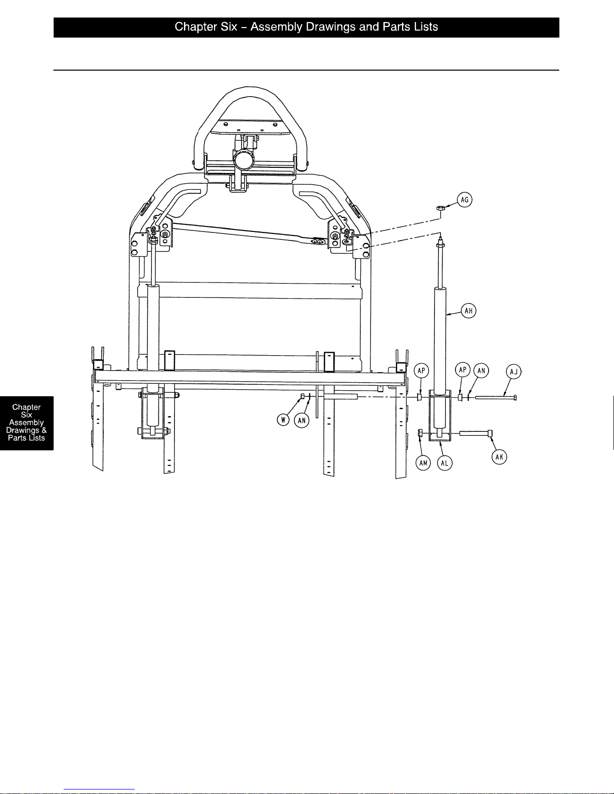
1069–32–15 Optional Single Articulating Pneumatic Fowler Ass’y
Cylinder Assembly – Both Sides
Item Part No. Part Name Qty.
A 1069–31–11 Rivet 4
B 1069–31–41 Handle Pivot Bracket, Left 1
C 1210–31–103 “L” Bracket 2
D 1069–31–46 Handle Pivot Bracket, Right 1
E 1069–31–75 Handle Weldment, Right 1
F 5050–531–200 Red Handle Cover 2
G 1069–31–31 Short Handle Adjustment Link 1
H7–50 Truss Hd. Screw 2
J15–3 Jam Nut 4
K 1069–31–70 Handle Weldment, Left 1
L 1069–31–32 Long Handle Adjustment Link 1
page 6–50
Page 90
1069–32–15 Optional Single Articulating Pneumatic Fowler Ass’y
Item Part No. Part Name Qty.
M 1069–32–75 Fowler Skin 1
N25–50 Pop Rivet 9
P7–42 Truss Hd. Screw 4
Q 1069–32–70 Fowler Weldment 1
R 1069–31–12 Barrel Nut 4
S7–62 Truss Hd. Screw 2
T 3001–300–99 Fowler Pivot Bushing 2
U14–87 Nylon Flat Washer 2
V11–180 Steel Flat Washer 2
W16–28 Nylock Nut 4
X13–18 External Tooth Lockwasher 2
Y7–19 Truss Hd. Screw 2
Z38–436 Extension Spring 2
AA 1069–33–110 Head Piece Weldment 1
AB 1069–33–108 Head Pivot Shaft 1
AC 1069–33–107 Hole Plug 2
AD 4–74 Button Hd. Screw 2
AE 4–54 Button Hd. Screw 2
AF 16–11 Nylock Nut 2
AG 15–59 M10 Nut 2
AH 360–31–77 Pneumatic Cylinder 2
AJ 3–37 Hex Hd. Cap Screw 2
AK 4–323 M10 Soc. Hd. Cap Screw 2
AL 1069–31–36 Cylinder Mounting Box 2
AM 16–90 M10 Nylock Nut 2
AN 11–63 Flat Washer 4
AP 52–86 Nyliner 4
AQ 7900–1–102 Velcro Pile 2
AR 1069–60–91 Fowler Release Label, Right 1
AS 1069–60–92 Fowler Release Label, Left 1
AT 11–179 Nylon Washer 4
AU 1069–31–13 Hole Plug 2
AV 966–70–36 Spacer 2
AW 3–20 Hex Hd. Cap Screw 1
AX 966–70–27 Bar Clamp 1
AY 21–73 Set Screw 1
AZ 3–78 Hex Hd. Cap Screw 1
BA 38–171 Compression Spring 1
BB 966–51–19 Modified Wedge Lock 1
BC 11–108 Steel Flat Washer 1
BD 966–51–18 Shaft 1
BE 4–66 Soc. Hd. Cap Screw 1
BF 966–51–24 Knob 1
BG 966–1–65 Label 1
BH 966–70–25 Slide Bar 1
BJ 966–70–37 Spacer 2
BK 14–20 Washer 2
BL 1010–91–57 Weight Label 2
page 6–51
Page 91
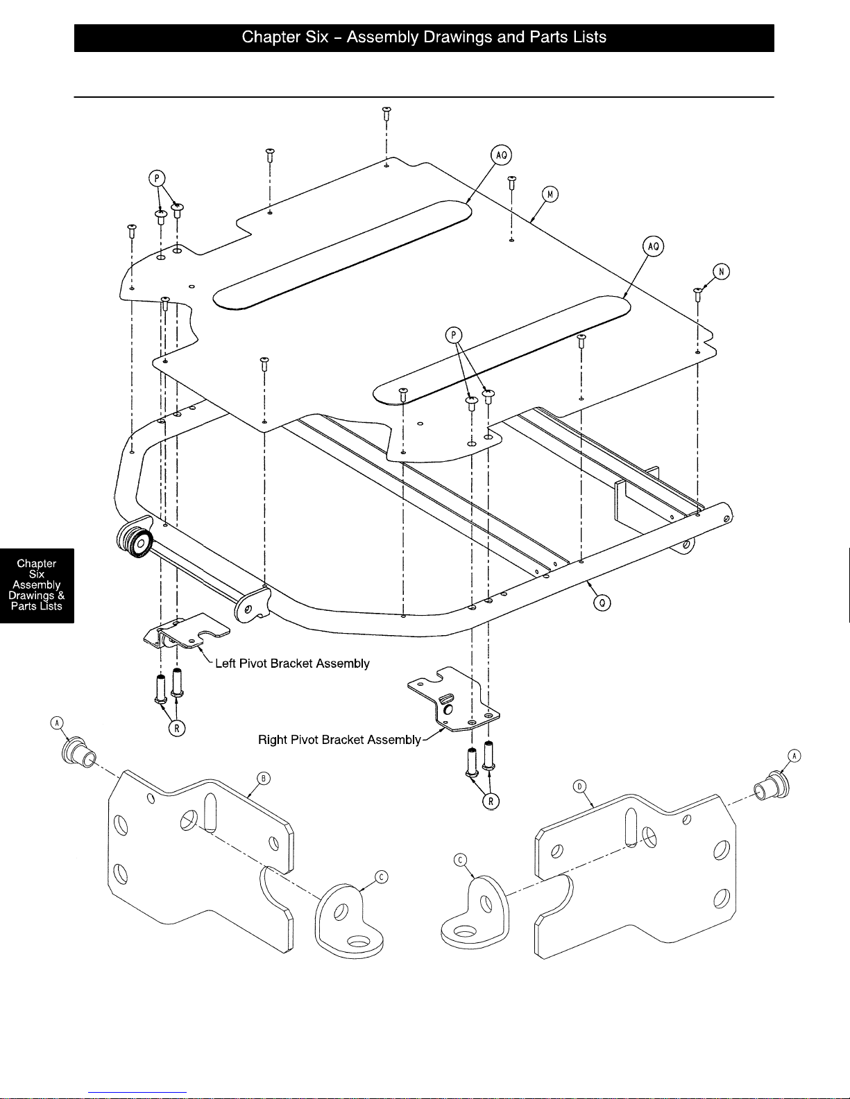
1069–32–10 Optional Dual Articulating Pneumatic Fowler Ass’y
LEFT PIVOT BRACKET ASSEMBLY RIGHT PIVOT BRACKET ASSEMBLY
page 6–52
Page 92
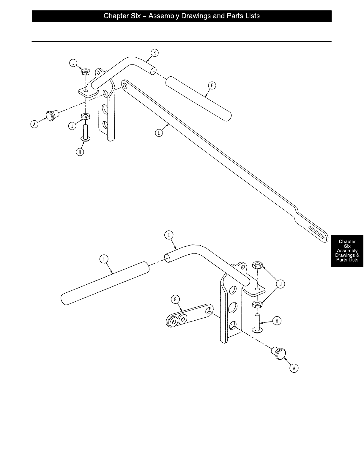
1069–32–10 Optional Dual Articulating Pneumatic Fowler Ass’y
Left Handle Assembly
Right Handle Assembly
page 6–53
Page 93
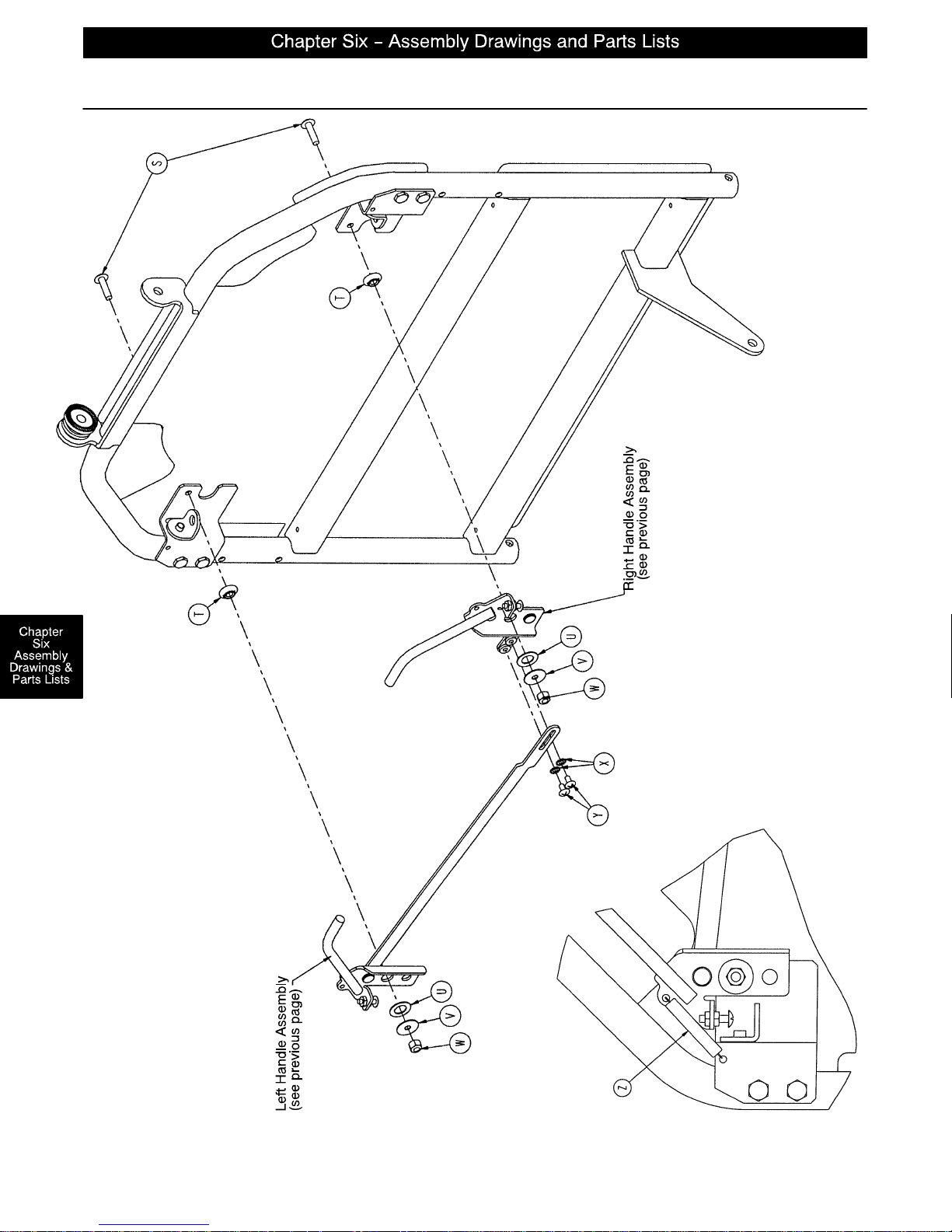
1069–32–10 Optional Dual Articulating Pneumatic Fowler Ass’y
page 6–54
BOTH SIDES
SPRING A TT ACHMENT
Page 94
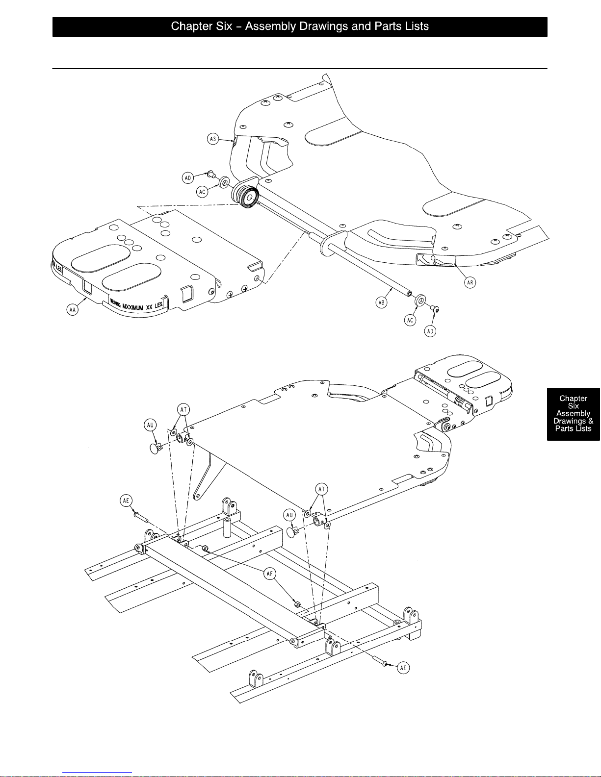
1069–32–10 Optional Dual Articulating Pneumatic Fowler Ass’y
page 6–55
Page 95
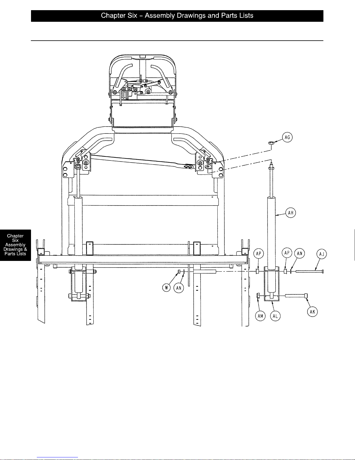
1069–32–10 Optional Dual Articulating Pneumatic Fowler Ass’y
page 6–56
CYLINDER ASSEMBLY – BOTH SIDES
Page 96
1069–32–10 Optional Dual Articulating Pneumatic Fowler Ass’y
Item Part No. Part Name Qty.
A 1069–31–11 Rivet 4
B 1069–31–41 Handle Pivot Bracket, Left 1
C 1210–31–103 “L” Bracket 2
D 1069–31–46 Handle Pivot Bracket, Right 1
E 1069–31–65 Handle Weldment, Right 1
F 1069–31–200 Red Handle Cover 2
G 1069–31–31 Short Handle Adjustment Link 1
H7–50 Truss Hd. Screw 2
J15–3 Jam Nut 4
K 1069–31–60 Handle Weldment, Left 1
L 1069–31–32 Long Handle Adjustment Link 1
M 1069–32–55 Fowler Skin 1
N25–50 Pop Rivet 9
P7–42 Truss Hd. Screw 4
Q 1069–32–50 Fowler Weldment 1
R 1069–31–12 Barrel Nut 4
S7–62 Truss Hd. Screw 2
T 3001–300–99 Fowler Pivot Bushing 2
U14–87 Nylon Flat Washer 2
V11–180 Steel Flat Washer 2
W16–28 Nylock Nut 4
X13–18 External Tooth Lockwasher 2
Y7–19 Truss Hd. Screw 2
Z38–436 Extension Spring 2
AA (page 6–70) Head Piece Assembly 1
AB 1069–33–93 Head Pivot Shaft 1
AC 52–17 Nylon Flat Washer 2
AD 4–74 Button Hd. Screw 2
AE 4–183 Button Hd. Screw 2
AF 16–11 Nylock Nut 2
AG 15–59 M10 Nut 2
AH 360–31–77 Pneumatic Cylinder 2
AJ 3–37 Hex Hd. Cap Screw 2
AK 4–323 M10 Soc. Hd. Cap Screw 2
AL 1069–31–36 Cylinder Mounting Box 2
AM 16–90 M10 Nylock Nut 2
AN 11–63 Flat Washer 4
AP 52–86 Nyliner 4
AQ 7900–1–102 Velcro Pile 2
AR 1069–60–91 Fowler Release Label, Right 1
AS 1069–60–92 Fowler Release Label, Left 1
AT 11–179 Nylon Washer 4
AU 1069–31–13 Hole Plug 2
page 6–57
Page 97
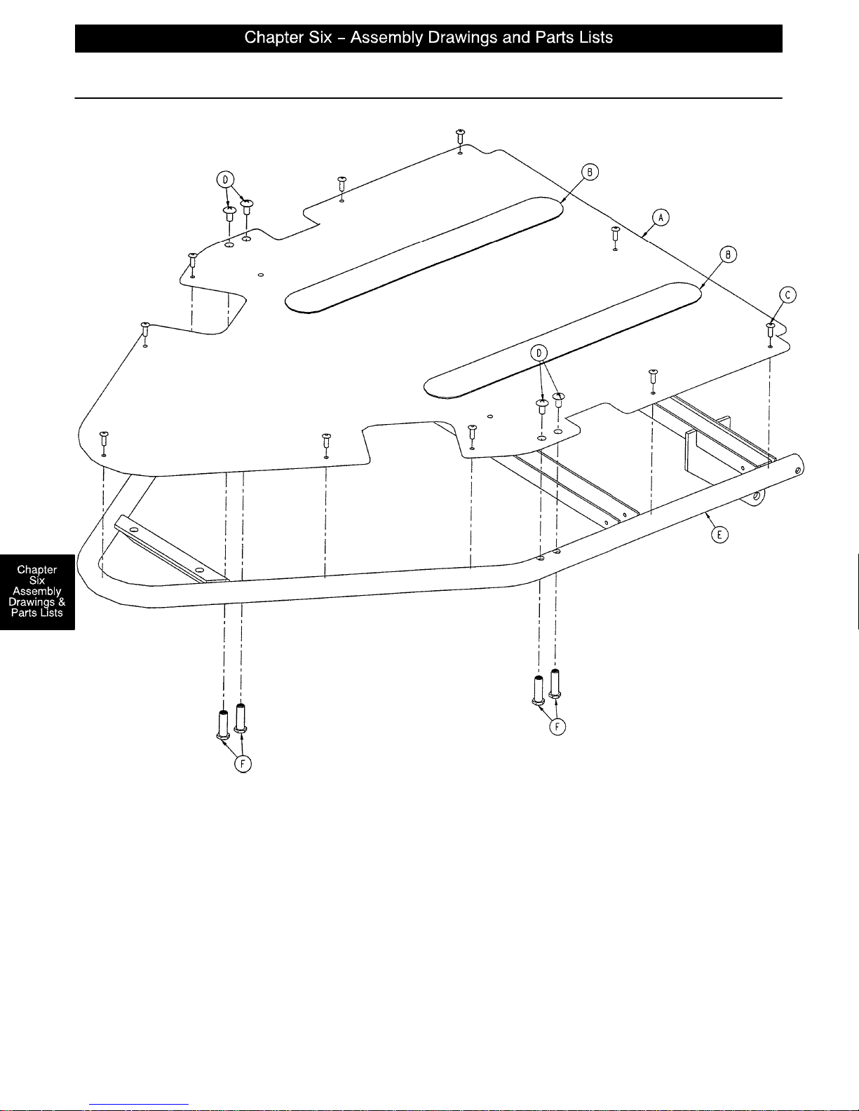
1069–42–60 Optional Zero Articulating Crank Fowler Assembly
page 6–58
Page 98
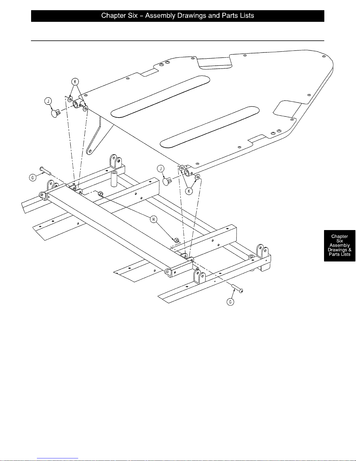
1069–42–60 Optional Zero Articulating Crank Fowler Assembly
Item Part No. Part Name Qty.
A 1069–32–65 Fowler Skin 1
B 7900–1–102 Velcro Pile 2
C25–50 Pop Rivet 10
D7–42 Truss Hd. Screw 4
E 1069–32–60 Fowler Weldment 1
F 1069–31–12 Barrel Nut 4
G4–54 Button Hd. Screw 2
H16–11 Nylock Nut 2
J 1069–31–13 Hole Plug 2
K11–17 Nylon Washer 4
page 6–59
Page 99
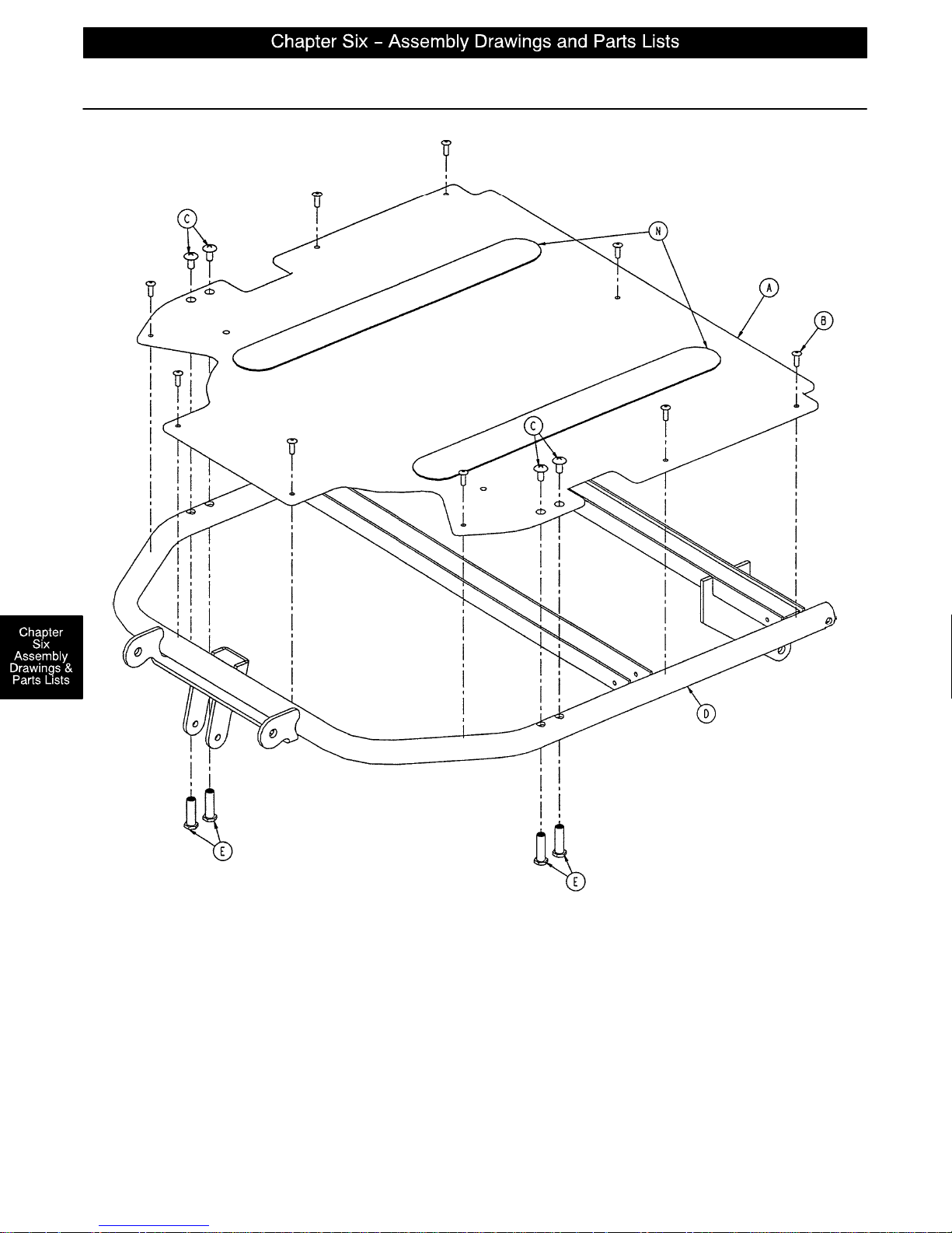
1069–42–55 Optional Single Articulating Crank Fowler Assembly
page 6–60
Page 100
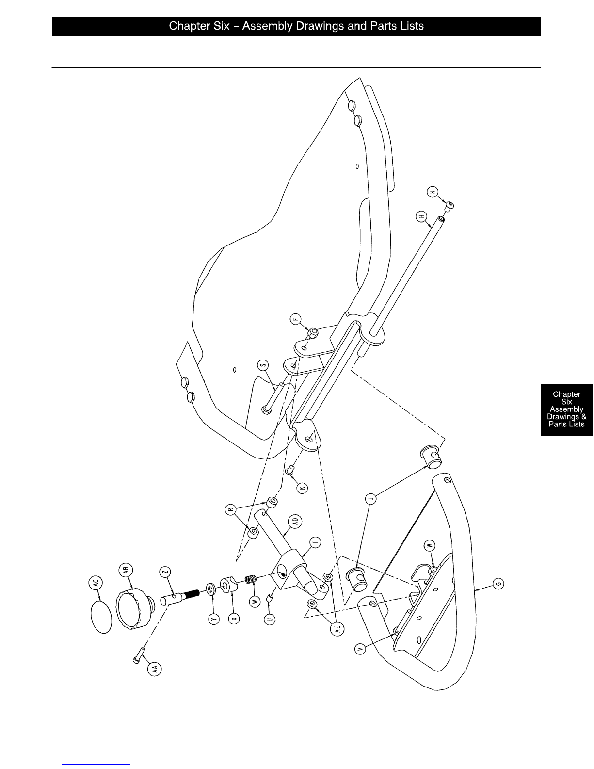
1069–42–55 Optional Single Articulating Crank Fowler Assembly
page 6–61
 Loading...