

Stryker 1020 Maintenance Manual
IMPORTANT
File in your
maintenance
records
Trauma Stretcher
Model 1020
MAINTENANCE MANUAL
For Parts or Technical Assistance
1−800−327−0770 (Option 2)

Table of Contents
Introduction
Specifications 3. . . . . . . . . . . . . . . . . . . . . . . . . . . . . . . . . . . . . . . . . . . . . . . . . . . . . . . . . . . . . . . . . . . . . . . . . . . .
Warning / Caution / Note Definition 3. . . . . . . . . . . . . . . . . . . . . . . . . . . . . . . . . . . . . . . . . . . . . . . . . . . . . . . . .
Preventative Maintenance
Checklist 4. . . . . . . . . . . . . . . . . . . . . . . . . . . . . . . . . . . . . . . . . . . . . . . . . . . . . . . . . . . . . . . . . . . . . . . . . . . . . . . .
Cleaning 5. . . . . . . . . . . . . . . . . . . . . . . . . . . . . . . . . . . . . . . . . . . . . . . . . . . . . . . . . . . . . . . . . . . . . . . . . . . . . . . .
Service Information
Caster Cover Installation and Removal 6. . . . . . . . . . . . . . . . . . . . . . . . . . . . . . . . . . . . . . . . . . . . . . . . . . . . . .
Caster Removal 6. . . . . . . . . . . . . . . . . . . . . . . . . . . . . . . . . . . . . . . . . . . . . . . . . . . . . . . . . . . . . . . . . . . . . . . . . .
Release Pedal Adjustment 7. . . . . . . . . . . . . . . . . . . . . . . . . . . . . . . . . . . . . . . . . . . . . . . . . . . . . . . . . . . . . . . .
Brake Rod Removal 7. . . . . . . . . . . . . . . . . . . . . . . . . . . . . . . . . . . . . . . . . . . . . . . . . . . . . . . . . . . . . . . . . . . . . .
Side Control Brake Rod Removal 8. . . . . . . . . . . . . . . . . . . . . . . . . . . . . . . . . . . . . . . . . . . . . . . . . . . . . . . . . . .
Brake Ring Removal 9. . . . . . . . . . . . . . . . . . . . . . . . . . . . . . . . . . . . . . . . . . . . . . . . . . . . . . . . . . . . . . . . . . . . . .
Fifth Wheel Assembly Removal 9. . . . . . . . . . . . . . . . . . . . . . . . . . . . . . . . . . . . . . . . . . . . . . . . . . . . . . . . . . . .
Big Wheel Hubcap Removal 10. . . . . . . . . . . . . . . . . . . . . . . . . . . . . . . . . . . . . . . . . . . . . . . . . . . . . . . . . . . . . .
Big Wheel Removal 10. . . . . . . . . . . . . . . . . . . . . . . . . . . . . . . . . . . . . . . . . . . . . . . . . . . . . . . . . . . . . . . . . . . . .
Litter Top Removal 11. . . . . . . . . . . . . . . . . . . . . . . . . . . . . . . . . . . . . . . . . . . . . . . . . . . . . . . . . . . . . . . . . . . . . .
Big Wheel Carriage Removal 11. . . . . . . . . . . . . . . . . . . . . . . . . . . . . . . . . . . . . . . . . . . . . . . . . . . . . . . . . . . . .
Big Wheel Cam Gas Spring Dampener Removal 12. . . . . . . . . . . . . . . . . . . . . . . . . . . . . . . . . . . . . . . . . . . .
Side Control Big Wheel Linkage Assembly Removal 12. . . . . . . . . . . . . . . . . . . . . . . . . . . . . . . . . . . . . . . . .
Jack Descent Rate Adjustment 13. . . . . . . . . . . . . . . . . . . . . . . . . . . . . . . . . . . . . . . . . . . . . . . . . . . . . . . . . . . .
Removal of Excess Air from the Hydraulic System 13. . . . . . . . . . . . . . . . . . . . . . . . . . . . . . . . . . . . . . . . . . .
Head End Hydraulic Jack Removal 14. . . . . . . . . . . . . . . . . . . . . . . . . . . . . . . . . . . . . . . . . . . . . . . . . . . . . . . .
Foot End Hydraulic Jack Removal 15, 16. . . . . . . . . . . . . . . . . . . . . . . . . . . . . . . . . . . . . . . . . . . . . . . . . . . . . .
Pneumatic Fowler Adjustment 16. . . . . . . . . . . . . . . . . . . . . . . . . . . . . . . . . . . . . . . . . . . . . . . . . . . . . . . . . . . .
Transfer Board Counterbalance Adjustment 17. . . . . . . . . . . . . . . . . . . . . . . . . . . . . . . . . . . . . . . . . . . . . . . . .
Siderail LatchAdjustment 17. . . . . . . . . . . . . . . . . . . . . . . . . . . . . . . . . . . . . . . . . . . . . . . . . . . . . . . . . . . . . . . . .
Replacement Parts and Kits 18. . . . . . . . . . . . . . . . . . . . . . . . . . . . . . . . . . . . . . . . . . . . . . . . . . . . . . . . . . . . . . . .
Assembly Drawings and Parts Lists
Fifth Wheel Base Assembly 19. . . . . . . . . . . . . . . . . . . . . . . . . . . . . . . . . . . . . . . . . . . . . . . . . . . . . . . . . . . . . .
Fifth Wheel Assembly 20, 21. . . . . . . . . . . . . . . . . . . . . . . . . . . . . . . . . . . . . . . . . . . . . . . . . . . . . . . . . . . . . . . . .
Base Assembly with Standard Brakes (Fifth Wheel Base) 22, 23. . . . . . . . . . . . . . . . . . . . . . . . . . . . . . . . . .
Brake Rod Assembly 24. . . . . . . . . . . . . . . . . . . . . . . . . . . . . . . . . . . . . . . . . . . . . . . . . . . . . . . . . . . . . . . . . . . .
Drive Link Assembly 25, 26. . . . . . . . . . . . . . . . . . . . . . . . . . . . . . . . . . . . . . . . . . . . . . . . . . . . . . . . . . . . . . . . . .
Caster Assembly 27. . . . . . . . . . . . . . . . . . . . . . . . . . . . . . . . . . . . . . . . . . . . . . . . . . . . . . . . . . . . . . . . . . . . . . . .
Base Assembly with Four−Sided Brakes 28, 29. . . . . . . . . . . . . . . . . . . . . . . . . . . . . . . . . . . . . . . . . . . . . . . .
Side Control Brake Rod Assembly 30. . . . . . . . . . . . . . . . . . . . . . . . . . . . . . . . . . . . . . . . . . . . . . . . . . . . . . . . .
Brake Rod Assembly 31. . . . . . . . . . . . . . . . . . . . . . . . . . . . . . . . . . . . . . . . . . . . . . . . . . . . . . . . . . . . . . . . . . . .
Base Assembly with Dual Side Hydraulics (Fifth Wheel Base) 32−34. . . . . . . . . . . . . . . . . . . . . . . . . . . . . .
Release Pedal Assembly 35. . . . . . . . . . . . . . . . . . . . . . . . . . . . . . . . . . . . . . . . . . . . . . . . . . . . . . . . . . . . . . . . .
Pump Pedal Assembly 36. . . . . . . . . . . . . . . . . . . . . . . . . . . . . . . . . . . . . . . . . . . . . . . . . . . . . . . . . . . . . . . . . . .

Table of Contents
Assembly Drawings and Parts Lists
Base Assembly with Three Side Hydraulics (Fifth Wheel Base) 37−39. . . . . . . . . . . . . . . . . . . . . . . . . . . . .
Release Pedal Assembly 40. . . . . . . . . . . . . . . . . . . . . . . . . . . . . . . . . . . . . . . . . . . . . . . . . . . . . . . . . . . . . . . . .
Pump Pedal Assembly 41. . . . . . . . . . . . . . . . . . . . . . . . . . . . . . . . . . . . . . . . . . . . . . . . . . . . . . . . . . . . . . . . . . .
Base Labeling Assembly 42−44. . . . . . . . . . . . . . . . . . . . . . . . . . . . . . . . . . . . . . . . . . . . . . . . . . . . . . . . . . . . . .
Big Wheel Base Assembly 45−47. . . . . . . . . . . . . . . . . . . . . . . . . . . . . . . . . . . . . . . . . . . . . . . . . . . . . . . . . . . . .
Base Assembly with Standard Brakes (Big Wheel Base) 48, 49. . . . . . . . . . . . . . . . . . . . . . . . . . . . . . . . . . .
Drive Link Assembly 50. . . . . . . . . . . . . . . . . . . . . . . . . . . . . . . . . . . . . . . . . . . . . . . . . . . . . . . . . . . . . . . . . . . . .
Brake Rod Assembly 51. . . . . . . . . . . . . . . . . . . . . . . . . . . . . . . . . . . . . . . . . . . . . . . . . . . . . . . . . . . . . . . . . . . .
Base Assembly with Dual Side Hydraulics (Big Wheel Base) 52−54. . . . . . . . . . . . . . . . . . . . . . . . . . . . . . .
Release Pedal Assembly 55. . . . . . . . . . . . . . . . . . . . . . . . . . . . . . . . . . . . . . . . . . . . . . . . . . . . . . . . . . . . . . . . .
Cam Bracket Assembly 56, 57. . . . . . . . . . . . . . . . . . . . . . . . . . . . . . . . . . . . . . . . . . . . . . . . . . . . . . . . . . . . . . .
Big Wheel Carriage Assembly 58. . . . . . . . . . . . . . . . . . . . . . . . . . . . . . . . . . . . . . . . . . . . . . . . . . . . . . . . . . . .
Side Control Big Wheel Base Assembly 59−61. . . . . . . . . . . . . . . . . . . . . . . . . . . . . . . . . . . . . . . . . . . . . . . . .
Side Control Big Wheel Carriage Assembly 62, 63. . . . . . . . . . . . . . . . . . . . . . . . . . . . . . . . . . . . . . . . . . . . . .
Side Control Big Wheel Linkage Assembly 64. . . . . . . . . . . . . . . . . . . . . . . . . . . . . . . . . . . . . . . . . . . . . . . . . .
Base Labeling Assembly 65, 66. . . . . . . . . . . . . . . . . . . . . . . . . . . . . . . . . . . . . . . . . . . . . . . . . . . . . . . . . . . . . .
Variable Descent Hydraulic Jack Option 67. . . . . . . . . . . . . . . . . . . . . . . . . . . . . . . . . . . . . . . . . . . . . . . . . . . .
Constant Descent Hydraulic Jack Option 68. . . . . . . . . . . . . . . . . . . . . . . . . . . . . . . . . . . . . . . . . . . . . . . . . . .
Litter Assembly 69−73. . . . . . . . . . . . . . . . . . . . . . . . . . . . . . . . . . . . . . . . . . . . . . . . . . . . . . . . . . . . . . . . . . . . . .
Siderail Assembly 74. . . . . . . . . . . . . . . . . . . . . . . . . . . . . . . . . . . . . . . . . . . . . . . . . . . . . . . . . . . . . . . . . . . . . . .
Litter Support Assembly 75, 76. . . . . . . . . . . . . . . . . . . . . . . . . . . . . . . . . . . . . . . . . . . . . . . . . . . . . . . . . . . . . . .
Manual Fowler Assembly 77, 78. . . . . . . . . . . . . . . . . . . . . . . . . . . . . . . . . . . . . . . . . . . . . . . . . . . . . . . . . . . . . .
Pneumatic Fowler Assembly 79, 80. . . . . . . . . . . . . . . . . . . . . . . . . . . . . . . . . . . . . . . . . . . . . . . . . . . . . . . . . . .
Litter Covers 81, 82. . . . . . . . . . . . . . . . . . . . . . . . . . . . . . . . . . . . . . . . . . . . . . . . . . . . . . . . . . . . . . . . . . . . . . . . .
Transfer System Assembly 84−88. . . . . . . . . . . . . . . . . . . . . . . . . . . . . . . . . . . . . . . . . . . . . . . . . . . . . . . . . . . .
Push Handle Assembly 89−91. . . . . . . . . . . . . . . . . . . . . . . . . . . . . . . . . . . . . . . . . . . . . . . . . . . . . . . . . . . . . . .
X−Ray Tray Assembly 92−95. . . . . . . . . . . . . . . . . . . . . . . . . . . . . . . . . . . . . . . . . . . . . . . . . . . . . . . . . . . . . . . .
X−Ray Grid Holder Assembly 96. . . . . . . . . . . . . . . . . . . . . . . . . . . . . . . . . . . . . . . . . . . . . . . . . . . . . . . . . . . . .
Centering Guide Assembly 97. . . . . . . . . . . . . . . . . . . . . . . . . . . . . . . . . . . . . . . . . . . . . . . . . . . . . . . . . . . . . . .
Fowler X−Ray Cassette Assembly 98. . . . . . . . . . . . . . . . . . . . . . . . . . . . . . . . . . . . . . . . . . . . . . . . . . . . . . . . .
Removable I.V. Pole Assembly 99−107. . . . . . . . . . . . . . . . . . . . . . . . . . . . . . . . . . . . . . . . . . . . . . . . . . . . . . . .
Foot Board 108. . . . . . . . . . . . . . . . . . . . . . . . . . . . . . . . . . . . . . . . . . . . . . . . . . . . . . . . . . . . . . . . . . . . . . . . . . . .
O2 Bottle Holder 108. . . . . . . . . . . . . . . . . . . . . . . . . . . . . . . . . . . . . . . . . . . . . . . . . . . . . . . . . . . . . . . . . . . . . . .
Defibrillator Tray Assembly 109. . . . . . . . . . . . . . . . . . . . . . . . . . . . . . . . . . . . . . . . . . . . . . . . . . . . . . . . . . . . . .
Foot Extension/Defibrillator Tray Assembly 110. . . . . . . . . . . . . . . . . . . . . . . . . . . . . . . . . . . . . . . . . . . . . . . .
Stirrup Assembly 111−113. . . . . . . . . . . . . . . . . . . . . . . . . . . . . . . . . . . . . . . . . . . . . . . . . . . . . . . . . . . . . . . . . . .
C−Spine Cassette Holder Assembly 114−116. . . . . . . . . . . . . . . . . . . . . . . . . . . . . . . . . . . . . . . . . . . . . . . . . .
O2 Bottle Retainer Assembly 117. . . . . . . . . . . . . . . . . . . . . . . . . . . . . . . . . . . . . . . . . . . . . . . . . . . . . . . . . . . .
Mattresses and Siderail Pads 118, 119. . . . . . . . . . . . . . . . . . . . . . . . . . . . . . . . . . . . . . . . . . . . . . . . . . . . . . . .
Warranty
Obtaining Parts and Service 120. . . . . . . . . . . . . . . . . . . . . . . . . . . . . . . . . . . . . . . . . . . . . . . . . . . . . . . . . . . . .
Service Contract Coverage 120. . . . . . . . . . . . . . . . . . . . . . . . . . . . . . . . . . . . . . . . . . . . . . . . . . . . . . . . . . . . . .
Return Authorization 121. . . . . . . . . . . . . . . . . . . . . . . . . . . . . . . . . . . . . . . . . . . . . . . . . . . . . . . . . . . . . . . . . . . .
Freight Damage Claims 121. . . . . . . . . . . . . . . . . . . . . . . . . . . . . . . . . . . . . . . . . . . . . . . . . . . . . . . . . . . . . . . . .

Introduction
INTRODUCTION
This manual is designed to assist you with the maintenance of the Model 1020 Full−Length X−Ray Emergency Room Stretcher. Read it thoroughly before using the equipment or beginning any maintenance on it.
SPECIFICATIONS
Maximum Weight Capacity 500 pounds
Overall Bed Length/Width 83” / 31.5”
Minimum/Maximum Bed Height 21.5” / 36”
Fowler Angle 0 to 90 degrees
Trendelenburg/Reverse Trendelenburg −18_ to +18 _
Stryker reserves the right to change specifications without notice.
WARNING / CAUTION / NOTE DEFINITION
The words WARNING, CAUTION and NOTE carry special meanings and should be carefully reviewed.
WARNING
The personal safety of the patient or user may be involved. Disregarding this information could result in injury
to the patient or user.
CAUTION
These instructions point out special procedures or precautions that must be followed to avoid damaging the
equipment.
NOTE
This provides special information to make maintenance easier or important instructions clearer.
3

Preventative Maintenance
CHECKLIST
All fasteners secure
Siderails move and latch properly
Engage brake pedal and push on the stretcher to ensure all casters lock securely
Steer function working properly
All casters secure and swivel properly
Body restraints working properly
I.V. pole intact and operating properly
Oxygen bottle holder intact and operating properly
Fowler operates and latches properly
Trendelenburg/Reverse Trendelenburg operating properly
No rips or cracks in mattress cover
Transfer boards intact and operating properly
Arm board support levers intact and operating properly
Ground chain intact
No leaks at hydraulic connections
Hydraulic jacks holding properly
Hydraulic drop rate set properly
Hydraulic oil level sufficient
Lubricate where required
X−Ray tray slide tracks cleaned of dust and debris
Accessories and mounting hardware in good condition and working properly
Serial No.______________
______________
______________
______________
______________
Completed By:_________________________________ Date:_____________
NOTE
Preventative maintenance should be performed at a minimum of annually. A preventative maintenance program should be established for all Stryker Medical equipment. Preventative maintenance may need to be
performed more frequently based on the usage level of the product.
4

Cleaning
Hand wash all surfaces of the stretcher with warm water and mild detergent. Dry thoroughly. DO NOT
STEAM CLEAN, PRESSURE WASH, HOSE OFF OR ULTRASONICALLY CLEAN. Using these methods
of cleaning is not recommended and may void this product’s warranty.
Clean Velcro AFTER EACH USE. Saturate Velcro with disinfectant and allow disinfectant to evaporate. (Appropriate disinfectant for nylon Velcro should be determined by the hospital.)
In general, when used in those concentrations recommended by the manufacturer, either phenolic type or
quaternary type disinfectants can be used. Iodophor type disinfectants are not recommended for use because staining may result. The following products have been tested and have been found not to have a harmful effect WHEN USED IN ACCORDANCE WITH MANUFACTURERS RECOMMENDED DILUTION.*
*MANUFACTURER’S
TRADE NAME DISINFECTANT
TYPE
A33 Quaternary Airwick (Professional Products Division) 2 ounces/gallon
A33 (dry) Quaternary Airwick (Professional Products Division) 1/2 ounce/gallon
Beaucoup Phenolic Huntington Laboratories 1 ounce/gallon
Blue Chip Quaternary S.C. Johnson 2 ounces/gallon
Elimstaph Quaternary Walter G. Legge 1 ounce/gallon
Franklin Phenomysan F2500 Phenolic Purex Corporation 1 1/4 ounce/gallon
Franklin Sentinel Quaternary Purex Corporation 2 ounces/gallon
Galahad Phenolic Puritan Churchill Chemical Company 1 ounce/gallon
Hi−Tor Quaternary Huntington Laboratories 1/2 ounce/gallon
LPH Phenolic Vestal Laboratories 1/2 ounce/gallon
Matar Phenolic Huntington Laboratories 1/2 ounce/gallon
Omega Quaternary Airwick (Professional Products Division) 1/2 ounce/gallon
Quanto Quaternary Huntington Laboratories 1 ounce/gallon
Sanikleen Quaternary West Chemical Products 2 ounces/ gallon
Sanimaster II Quaternary Service Master 1 ounce/gallon
Vesphene Phenolic Vestal Laboratories 1 1/4 ounce/ gallon
MANUFACTURER
RECOMMENDED
DILUTION
Quaternary Germicidal Disinfectants, used as directed, and/or Chlorine Bleach products, typically 5.25% So dium Hypochlorite in dilutions ranging between 1 part bleach to 100 parts water, and 2 parts bleach
to 100 parts water are not considered mild detergents. These products are corrosive in nature and
may cause damage to your stretcher if used improperly. If these types of products are used to clean
Stryker patient handling equipment, measures must be taken to insure the stretchers are rinsed with clean
water and thoroughly dried following cleaning. Failure to properly rinse and dry the stretchers will leave a corrosive residue on the surface of the stretcher, possibly causing premature corrosion of critical components.
NOTE
Failure to follow the above directions when using these types of cleaners may void this product’s warranty.
REMOVAL OF IODINE COMPOUNDS
This solution may be used to remove iodine stains from mattress cover surfaces.
1. Use a solution of 1−2 tablespoons Sodium Thiosulfate in a pint of warm water to clean the stained area.
Clean as soon as possible after staining occurs. If stains are not immediately removed, allow solution to
soak or stand on the surface.
2. Rinse surfaces which have been exposed to the solution in clear water before returning bed to service.
5
Service Information
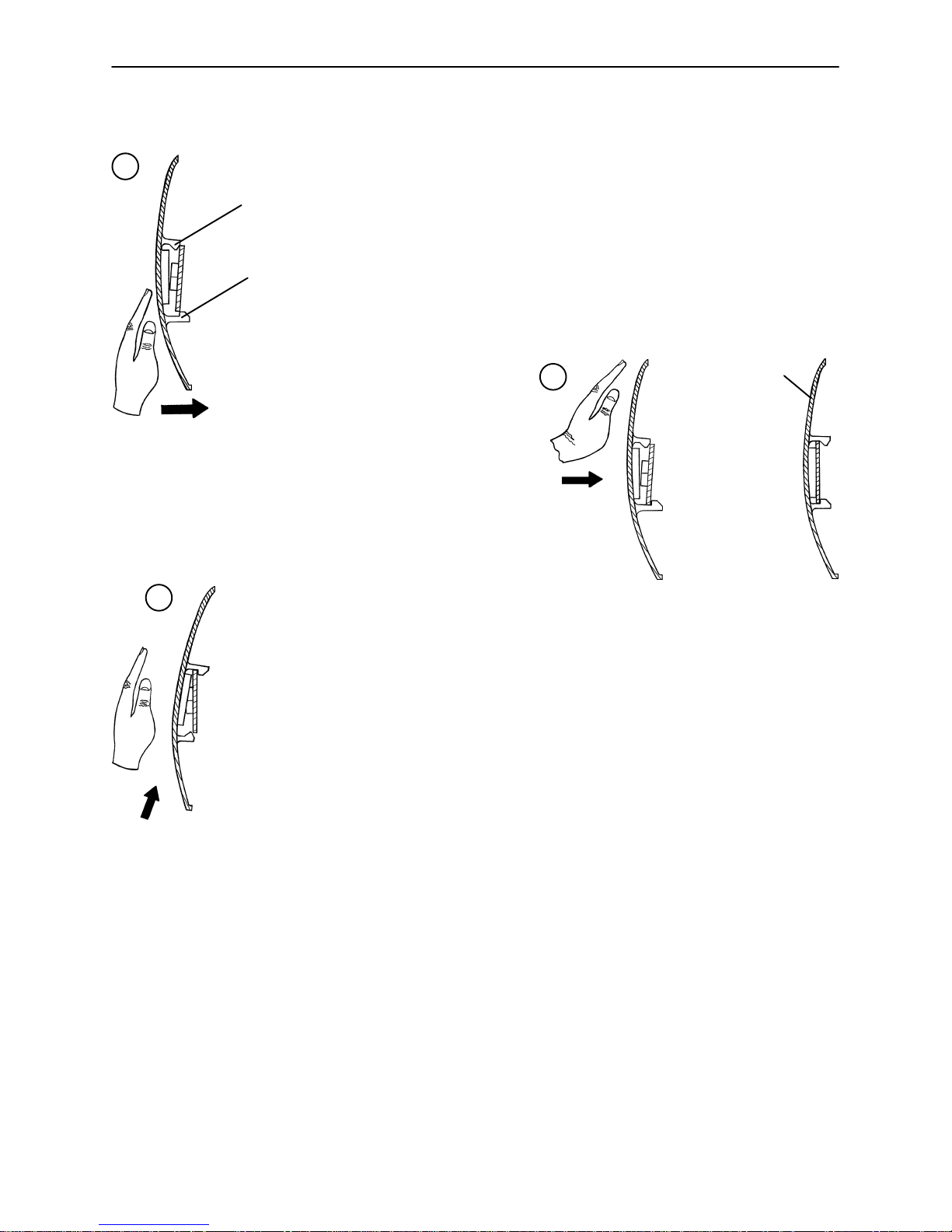
CASTER COVER INSTALLATION AND REMOVAL
1.
Double Prongs
Looking through the larger of the two side cut−outs,
align the cover with the axle nut or bolt head, as shown.
Single Prong
Push down on the opposite side of the cover until the
single prong engages the caster horn.
3.
Top View (Cut−Away)
Push on the cover with your palm until
the double prongs engage.
To remove the wheel cover, insert a large screwdriver into the cut−out
in the side of the wheel cover and into the space between the double
prongs. Pry up the cover to disengage the double prongs and push
sharply upward to disengage the single prong.
Top View (Cut−Away)
2.
Properly Attached
Cover
Top View (Cut−Away)
CASTER REMOVAL
Required Tools:
9/16” Open End Wrench
1. Remove the caster cover.
2. While keeping pressure on the caster bolt with your index finger, use a 9/16” open end wrench to remove
the nylock hex nut on top of the caster assembly.
3. Using the brake ring, lift up on the base assembly and pull the caster assembly down to remove it.
4. Reverse steps 1−3 to install the new caster.
6

Service Information
RELEASE PEDAL ADJUSTMENT
1. Manually disengage the release pedal swivel (item K on page 33) from the release pedal assembly.
2. To increase the release rod engagement with the release valve, turn the release pedal swivel clockwise
on the threaded release rod.
3. To decrease the release rod engagement with the release valve, turn the release pedal swivel counter-
clockwise on the threaded release rod.
NOTE
If the pedal swivel assembly is threaded too far onto the release rod, the release valve will be partially activated and the jack will drift.
BRAKE ROD REMOVAL
Required Tools:
Hammer 7/32” Punch String or Bungee Cords
Fifth Wheel Base
1. Pump the litter up to full height.
2. Lift the base hood and support it from the litter using string or bungee cords.
3. Remove the hex head cap screws connecting the brake rod supports to the base frame.
4. Remove the bolt connecting the drive link assembly to the fifth wheel cam.
5. Remove the rue ring cotter and clevis pin connecting the rod end link to the side control link.
6. Remove the rue ring cotter connecting the drive link assembly to the bearing pivot support on the base
frame (under the brake ring weldment).
7. Remove the three hex washer head screws holding the brake rod assembly to the base frame.
8. Remove the slotted spring pins connecting the butterfly “V” pedals, drive link assemblies and side control
link to the brake rod.
9. Reverse steps 1−8 to reinstall the brake rod. When reinstalling the brake rod supports, torque the hex
head cap screws to 12−15 ft.−lbs.
CAUTION
When reattaching the brake rod assembly to the base frame, set the torque specs no higher than 15 ft.−lbs.
or damage could occur to the bolts.
Big Wheel Base
1. Pump the litter up to full height.
2. Lift the base hood and support it from the litter using string or bungee cords.
3. With the brake/steer pedal in the steer position, remove the clevis pin and rue ring cotter connecting the
brake rod to the brake rod drive link at each end of the stretcher.
4. Remove the two clevis pins and rue ring cotters connecting the brake rods to the drive arm at the center
of the base near the cam bracket assembly.
5. Pull on the butterfly “V” pedals to remove the brake rods from the base.
6. Reverse steps 1−5 to reinstall the brake rod.
7

Service Information
SIDE CONTROL BRAKE ROD REMOVAL
Required Tools:
Hammer 7/32” Punch Needle Nose Pliers String or Bungee Cords
Fifth Wheel Base
1. Pump the litter up to full height.
2. Lift the base hood and support it from the litter using string or bungee cords.
3. Remove the rue ring cotter and clevis pin connecting the rod end link to the side control link.
4. Remove the four bolts holding the brake rod assembly to the base frame and remove the entire assembly.
5. Using a hammer and 7/32” punch, drive the slotted spring pin out of the butterfly “V” pedal on the patient’s
left side and remove the pedal,
6. Using a hammer and 7/32” punch, drive the slotted spring pin out of the hard stop in the center of the
support weldment.
7. Using a hammer and 7/32” punch, drive out the slotted spring pin connecting the side control link to the
side control brake rod on the patient’s right side.
8. Pull on the butterfly “V” pedal on the patient’s right side to remove the side control brake rod from the base.
9. Reverse steps 1−8 to reinstall the brake rod. When reinstalling the assembly, torque the hex head cap
screws to 12−15 ft.−lbs.
CAUTION
When reattaching the brake rod assembly to the base frame, set the torque specs no higher than 15 ft.−lbs.
or damage could occur to the bolts.
Big Wheel Base
1. Pump the litter up to full height.
2. Lift the base hood and support it from the litter using string or bungee cords.
3. Using a hammer and 7/32” punch, drive the groove pin out of the butterfly “V” pedal on the patient’s left
side and remove the pedal.
4. Using a hammer and 7/32” punch, drive out the groove pin connecting the side control link to the side
control brake rod.
5. Pull on the butterfly “V” pedal on the patient’s right side to remove the side control brake rod from the base.
6. Reverse steps 1−5 to reinstall the brake rod.
8

Service Information
BRAKE RING REMOVAL
Required Tools:
9/16” Socket w/Extension 3/8” Drive Ratchet Needle−Nose Pliers String or Bungee Cord
1. Pump the litter up to full height.
2. Lift the base hood and support it from the litter using string or bungee cords.
3. Using needle−nose pliers, unhook the extension springs from the top of the base caster tubes.
4. Remove the plastic caster covers.
5. While putting pressure on the caster carriage bolt, use a 9/16” socket and a 3/8” drive ratchet to remove
the caster nut on both sides of the stretcher.
6. Remove the casters.
7. Remove the brake rod (see procedure).
8. Remove the cotter pin from the clevis pin in the center of the brake ring weldment.
9. Remove the cotter pin from the bearing pivot support.
10. Remove the 3/4” nylock hex nut from the bearing pivot support.
11. Remove the drive link assembly.
12. Pull the brake ring down and out away from the stretcher base frame.
13. Reverse steps 1−12 to reinstall the brake ring.
FIFTH WHEEL ASSEMBLY REMOVAL
Required Tools:
1/2” Socket 3/8” Drive Ratchet
1. Using a 1/2” socket and 3/8” drive ratchet, remove the 1/2” bolt holding the fifth wheel cam drive link and
fifth wheel drive link to the fifth wheel cam.
2. Remove the two 1/2” bolts holding the fifth wheel mounting bracket to the base frame weldment.
3. Remove the fifth wheel assembly.
4. Reverse steps 1 and 2 to reinstall the fifth wheel.
9
Service Information
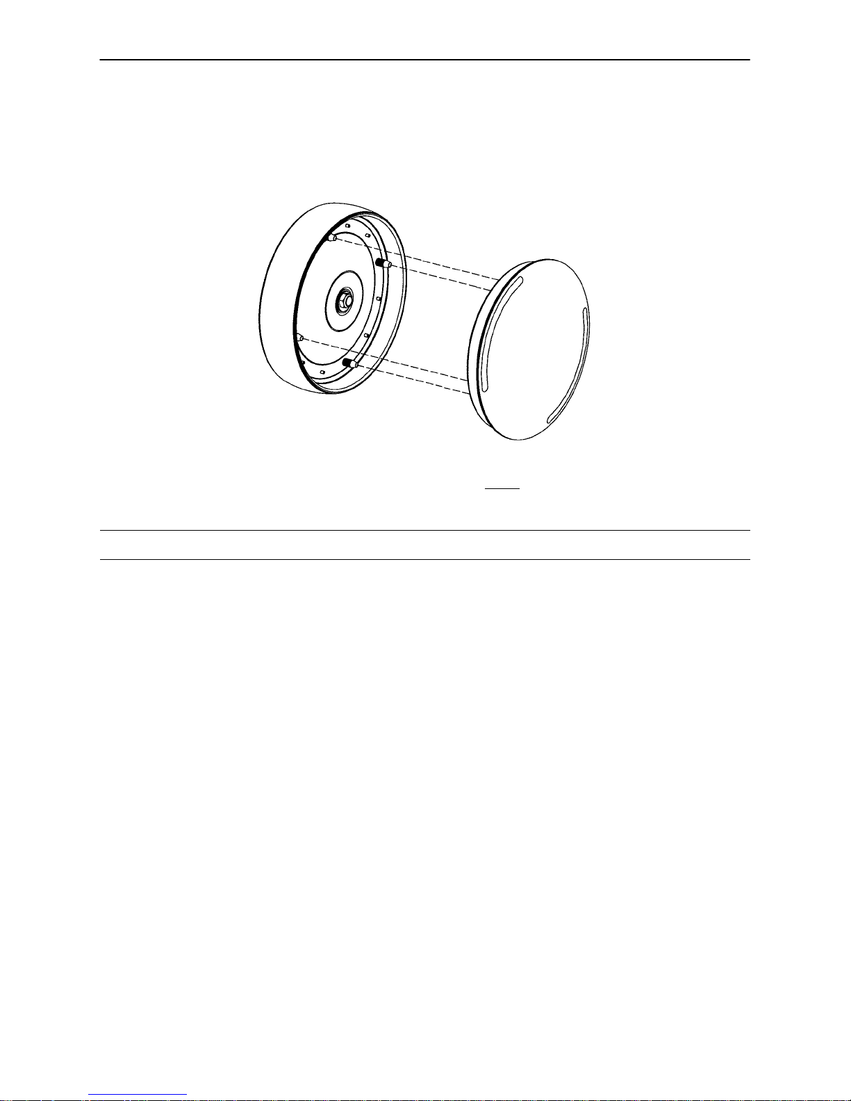
BIG WHEEL HUBCAP REMOVAL
Required Tools:
Large Standard Screwdriver
1. Using a large standard screwdriver, pry evenly around the entire edge of the Big Wheel hubcap until it
pops off the mounting studs on the wheel.
CAUTION
Do not attempt to pull off the hubcap after prying up only one side. Damage to the slots on the hubcap or
the mounting studs on the wheel could result.
2. To reinstall the hubcap, place it on the wheel, aligning the slots in the hubcap with the mounting studs
on the wheel. Press down evenly on the edges of the hubcap until it snaps into place.
BIG WHEEL REMOVAL
Required Tools:
Large Standard Screwdriver Small Standard Screwdriver String or Bungee Cords
1. Lift the base hood and separate the Velcro holding it to the base frame. Support the hood from the litter
using bungee cords so it is out of the way.
2. Using a large, standard screwdriver, pop off the big wheel cover.
3. Using a small, standard screwdriver, remove the spiral retaining ring from the groove on the Big Wheel
axle.
4. Remove the Big Wheel.
5. Reverse steps 1−4 to reinstall the Big Wheel.
10

Service Information
LITTER TOP REMOVAL
Required Tools:
1/2” Socket w/Extension 3/8” Drive Ratchet Standard Screwdriver
1. Using the foot pedal, pump up the litter top to full height.
2. Remove the stretcher mattress
3. Remove the round, black hole plugs from the jack supports at each end of the litter to expose the jack
support tube truss head screws.
4. Using a 1/2” socket, and a 3/8” drive ratchet, remove the truss head screws holding the jack support tubes
to the jack shafts.
5. Thread a 7/16−20 fine thread bolt far enough into the top of the jack supports to separate the litter top
from the jack shaft.
6. With the assistance of another person, lift the litter straight up to remove it from the jack shafts and set
it aside.
BIG WHEEL CARRIAGE ASSEMBLY REMOVAL
Required Tools:
1/2” Socket 3/8” Drive Ratchet Needle−Nose Pliers
1. Remove the litter top from the stretcher (see above).
2. Lift the base hood off the base frame.
3. With the brake/steer pedal in the steer position, remove the clevis pin and rue ring cotter connecting the
brake rod to the brake rod drive link at each end of the stretcher.
4. Remove the two clevis pins and rue ring cotters connecting the brake rods to the drive arm at the center
of the base near the cam bracket assembly.
5. Pull the brake shafts straight out away from the base.
6. Remove the four hex washer head screws holding the cam bracket assembly to the base frame and re-
move the cam bracket assembly.
NOTE
On a base with 4−sided brakes, remove the rue ring cotter and clevis pin connecting the side control big wheel
linkage assembly to the yoke weldment on the end control brake pad at the foot end of the stretcher.
7. Remove the two hex washer head screws holding the carriage weldment to the base frame and remove
the carriage assembly.
8. Reverse steps 1−7 to reinstall the carriage assembly.
11

Service Information
BIG WHEEL CAM GAS SPRING DAMPENER REMOVAL
Required Tools:
1/2” Socket 3/8” Drive Ratchet Needle−Nose Pliers
1. Remove the litter top from the stretcher (see page 11).
2. Lift the base hood off the base frame.
3. Remove the two clevis pins and rue ring cotters connecting the brake rods to the drive arm at the center
of the base near the cam bracket assembly.
4. Pull the brake shafts straight out away from the base.
5. Remove the four hex washer head screws holding the cam bracket assembly to the base frame and re-
move the cam bracket assembly.
6. Remove the rue ring cotter from the dampener mounting pin and remove the pin.
7. Lift up on the (patient) left side of the cam bracket and remove the rue ring cotter holding the dampener
to the dampener arm and remove the dampener.
8. Reverse steps 1−7 to install the new dampener.
SIDE CONTROL BIG WHEEL LINKAGE ASSEMBLY REMOVAL
Required Tools:
1/4” Punch Hammer Needle−Nose Pliers
String or Bungee Cords
1. Pump the litter up to full height.
2. Lift the base hood and support it from the litter using string or bungee cords.
3. Using a hammer and 1/4” punch, drive out the slotted spring pin connecting the butterfly “V” pedal on the
patient’s right side to the side control wheel axle.
4. Remove the butterfly “V” pedal and set it aside.
5. Using the hammer and 1/4” punch, drive out the slotted spring pin holding the side control Big Wheel link-
age yoke weldment to the side control wheel axle.
6. Pull straight out on the patient’s left side butterfly “V” pedal and remove the side control wheel axle.
7. Using needle−nose pliers, remove the hair pin cotter and washer holding the toggle pivot plate to the side
control Big Wheel carriage assembly.
8. Remove the rue ring cotter and clevis pin connecting the side control Big Wheel linkage rod end link to
the end control brake rod.
9. Remove the side control Big Wheel linkage assembly and set it aside.
10. Reverse steps 1−9 to reinstall the linkage assembly.
12

Service Information
JACK DESCENT RATE ADJUSTMENT
Required Tools:
Screwdriver Bungee Cords (or equivalent)
Adjustment Procedure:
1. Pump the litter up to full height.
2. Lift the base hood, separating the hood from the base frame. Support the hood from the litter using bun-
gee cords so it is out of the way.
3. The descent rate needle valve is located on the base of the jack. Turning the needle valve clockwise,
with a screwdriver, will decrease the rate of descent. Turning it counterclockwise will increase the rate
of descent.
NOTE
The larger percentage of a patient’s weight is located in the torso area. Adjust descent rate accordingly.
4. Remove the bungee cords supporting the base hood and secure the hood to the base frame.
NOTE
The jack descent rate is preset at the factory and adjustment is not recommended.
REMOVAL OF EXCESS AIR (VACUUM) FROM THE HYDRAULIC SYSTEM
1. Verify all hydraulic linkages are secure and operating properly.
2. Using the pump pedal, actuate the system several times to force the air through the system. The jack
should now raise properly.
13

Service Information
HEAD END HYDRAULIC JACK REMOVAL
Required Tools:
1. Remove the litter top from the stretcher (see page 11).
2. Using a 1/2” socket with extension and a 3/8” drive ratchet, remove the two hex head screws holding the
jack base to the stretcher base frame.
3. Remove the two hex head screws holding the jack reservoir clamp to the base frame and remove the
clamps.
4. Lift straight up on the pump connecting rod and disconnect the pump piston from the connecting rod.
5. Disconnect the pump pedal swivel from the release pedal mounting plate.
6. Remove the head end release rod from the release valve assembly.
7. Using a 1/2” socket with extension and a 3/8” drive ratchet, remove the two hex head screws holding the
jack base to the stretcher base frame.
8. Lift out the jack assembly.
9. To reinstall the jack, install the bolts on the jack and reservoir clamp but do not tighten them fully.
10. Reinstall the pump connecting rod and release rod.
11. Depress the pump pedal fully (to the floor). This will properly locate the jack onto the base frame.
12. Tighten the bolts on the jack and reservoir clamp.
13. Pump up the litter and apply weight to verify the jacks hold and do not drift.
1/2” Socket w/Extension 3/8” Drive Ratchet
NOTE
The jack descent rate is preset at the factory and adjustment is not recommended.
14

Service Information
FOOT END HYDRAULIC JACK REMOVAL (BASE WITH DUAL CONTROLS)
Required Tools:
1/2” Socket 3/8” Drive Ratchet Pliers
1. Remove the litter top from the stretcher (see page 11).
2. Lift the base hood off the base frame.
3. Remove the two hex washer head screws and washers connecting the pump pedal link to the foot end
pump pedal assembly and pump connecting rod.
4. Remove the foot end release rod from the release valve on the jack assembly by dislodging the release
pedal swivel from the pins on the release pedal weldment.
5. Dislodge the jack pump piston from the pump connecting rod.
6. Remove the two hex washer head screws holding the reservoir clamp.
7. Remove the jack assembly.
8. Reverse steps 1−7 to install the new jack.
NOTE
The jack descent rate is preset at the factory and adjustment is not recommended.
FOOT END HYDRAULIC JACK REMOVAL (BASE WITH 3−SIDED CONTROLS)
Required Tools:
1/2” Socket 3/8” Drive Ratchet Pliers
1. Remove the litter top from the stretcher (see page 11).
2. Lift the base hood off the base frame.
3. Remove the two hex washer head screws and washers connecting the pump pedal link to the foot end
pump pedal assembly and pump connecting rod.
4. Remove the foot end pump pedal return spring.
5. Remove the cotter pin from the center of the foot end pump pedal assembly and slide out the pivot pin.
6. Slide the foot end pump pedal assembly up and over the foot end mounting bracket.
7. Remove the four hex washer head screws fastening the foot end mounting bracket to the base frame
and set the bracket aside.
8. Remove the foot end release rod from the release valve on the jack assembly by dislodging the release
pedal swivel from the pins on the release pedal weldment.
9. Dislodge the jack pump piston from the pump connecting rod.
10. Remove the two hex washer head screws holding the reservoir clamp.
11. Remove the jack assembly.
12. Reverse steps 1−11 to install the new jack.
NOTE
The jack descent rate is preset at the factory and adjustment is not recommended.
15

Service Information
FOOT END HYDRAULIC JACK REMOVAL (BIG WHEEL BASE WITH 3−SIDED CONTROLS)
Required Tools:
1/2” Socket 3/8” Drive Ratchet Pliers
1. Remove the litter top from the stretcher (see page 11).
2. Lift the base hood off the base frame.
3. Remove the hair pin cotter and washer connecting the side control Big Wheel linkage toggle pivot plates
to the side control Big Wheel carriage weldment.
4. Remove the rue ring cotter and clevis pin connecting the side control Big Wheel rod end link to the yolk
weldment on the end control brake rod.
5. Remove the Big Wheel carriage assembly (see page 11).
6. Remove the two hex washer head screws and washers connecting the pump pedal link to the foot end
pump pedal assembly and pump connecting rod.
7. Remove the foot end pump pedal return spring.
8. Remove the cotter pin from the center of the foot end pump pedal assembly and slide out the pivot pin.
9. Slide the foot end pump pedal assembly up and over the foot end mounting bracket.
10. Remove the four hex washer head screws fastening the foot end mounting bracket to the base frame
and set the bracket aside.
1 1. Remove the foot end release rod from the release valve on the jack assembly by dislodging the release
pedal swivel from the pins on the release pedal weldment.
12. Dislodge the jack pump piston from the pump connecting rod.
13. Remove the two hex washer head screws holding the reservoir clamp.
14. Remove the jack assembly.
15. Reverse steps 1−11 to install the new jack.
NOTE
The jack descent rate is preset at the factory and adjustment is not recommended.
PNEUMATIC FOWLER ADJUSTMENT
Required Tools:
5/32” Hex Allen Wrench 1/2” Open End Wrench
1. Refer to the pneumatic Fowler assembly drawing on page 80 for parts reference.
2. For easier access, raise the Fowler to 75_ or higher.
3. Using a 1/2” open end wrench, loosen the hex nuts (item H) in the actuator arms on the end of the trip
bar (item B).
4. To adjust the Fowler, use a 5/32” hex Allen wrench to turn the Allen screws (item R) 1 to 2 turns counter−clockwise if the Fowler will not move or 1 to 2 turns clockwise if the Fowler will not hold its position.
5. Retighten the hex nuts. Be sure the Fowler travels from flat up to 90_ and down again and holds its position when weight is applied before returning the stretcher to service.
16

Service Information
TRANSFER BOARD COUNTERBALANCE ADJUSTMENT
Required Tools:
7/16 Open End Wrench
1. Raise the transfer board to the full up position.
2. Unhook the extension spring at the eye bolt.
3. Using a 7/16 open end wrench, loosen the jam nut at the eye bolt.
4. Adjust the eye bolt to the desired position.
5. Tighten the jam nut.
6. Hook the extension spring to the eye bolt.
7. Allow the transfer board to lower on its own.
8. Repeat steps 1−7 until the desired counterbalance is achieved.
FOLDDOWN SIDERAIL LATCH ADJUSTMENT
Required Tools:
1/8” Hex Allen Wrench
WARNING
The siderail latches are preset at the factory, and do not normally need adjustment. If adjustment must be
done, it is important to follow the procedure below. If adjustment is not done properly, injury to the patient
or user could result.
1. Using a 1/8” hex Allen wrench, adjust the hex Allen screw located on the latch assembly opposite the
latch. Turning the screw clockwise will DECREASE the amount of ”play” in the latching mechanism.
Turning counterclockwise will INCREASE the amount.
NOTE
The amount of ”play” in the siderail, when in full up engaged position, should be approximately 1/8 to 3/16
inches.
CAUTION
Too much ”play” when the siderail is in the full up engaged position will give the siderail the appearance of
being unstable and could also cause premature wearing of the latch system.
Too little ”play” will obstruct the latch and keep it from engaging completely in the full up position, which may
result in damage to the latch and/or injury to the patient or user.
17

Replacement Parts and Kits
PART NAME PART NUMBER
Caster Cover Kit 1010−056−100. . . . . . . . . . . . . . . . . . . . . . . . . . . . . . . . . . . . . . . . . . . . . . . . . . . . .
Centering Label, X−Ray Tray 1020−019−005. . . . . . . . . . . . . . . . . . . . . . . . . . . . . . . . . . . . . . . . . .
Full−Length X−Ray Tray, Left Side Load 1020−021−010. . . . . . . . . . . . . . . . . . . . . . . . . . . . . . . .
Full−Length X−Ray Tray, Right Side Load 1020−022−010. . . . . . . . . . . . . . . . . . . . . . . . . . . . . . .
Foot Board/Chartholder 0741−034−100. . . . . . . . . . . . . . . . . . . . . . . . . . . . . . . . . . . . . . . . . . . . . . .
Head/Foot Board 0741−029−100. . . . . . . . . . . . . . . . . . . . . . . . . . . . . . . . . . . . . . . . . . . . . . . . . . . . .
Hydraulic Jack, Constant Descent 0753−002−001. . . . . . . . . . . . . . . . . . . . . . . . . . . . . . . . . . . . . .
Hydraulic Jack, Variable Descent 0753−002−070. . . . . . . . . . . . . . . . . . . . . . . . . . . . . . . . . . . . . . .
Instrument/Serving Tray 1052−129−000. . . . . . . . . . . . . . . . . . . . . . . . . . . . . . . . . . . . . . . . . . . . . . .
I.V. Caddy 1050−001−100. . . . . . . . . . . . . . . . . . . . . . . . . . . . . . . . . . . . . . . . . . . . . . . . . . . . . . . . . . .
I.V. Pole, 2−Stage, Permanent, Foot End 1010−080−100. . . . . . . . . . . . . . . . . . . . . . . . . . . . . . .
I.V. Pole, 2−Stage, Permanent, Head End 1010−081−100. . . . . . . . . . . . . . . . . . . . . . . . . . . . . . .
I.V. Pole, 3−Stage, Permanent, Head End 1020−061−000. . . . . . . . . . . . . . . . . . . . . . . . . . . . . . .
I.V. Pole, 3−Stage, Permanent, Foot End 1020−062−000. . . . . . . . . . . . . . . . . . . . . . . . . . . . . . .
I.V. Pole, Tethered 1010−022−100. . . . . . . . . . . . . . . . . . . . . . . . . . . . . . . . . . . . . . . . . . . . . . . . . . . .
I.V. Pole, Standard, Removable 0390−025−000. . . . . . . . . . . . . . . . . . . . . . . . . . . . . . . . . . . . . . . .
Mattress, 3” Standard 1059−326−140. . . . . . . . . . . . . . . . . . . . . . . . . . . . . . . . . . . . . . . . . . . . . . . .
Mattress, 4” Standard 1059−426−140. . . . . . . . . . . . . . . . . . . . . . . . . . . . . . . . . . . . . . . . . . . . . . . .
Mattress, 3” Enhanced Comfort 1001−048−106. . . . . . . . . . . . . . . . . . . . . . . . . . . . . . . . . . . . . . . .
Mattress, 4” Enhanced Comfort 1001−047−106. . . . . . . . . . . . . . . . . . . . . . . . . . . . . . . . . . . . . . .
Mattress, 4” Ultra Comfort 1210−040−000. . . . . . . . . . . . . . . . . . . . . . . . . . . . . . . . . . . . . . . . . . . . .
Mattress, 5” Ultra Comfort 1210−050−000. . . . . . . . . . . . . . . . . . . . . . . . . . . . . . . . . . . . . . . . . . . .
Oxygen Bottle Holder 1020−030−000. . . . . . . . . . . . . . . . . . . . . . . . . . . . . . . . . . . . . . . . . . . . . . . . .
Paint, Touch−Up, Gloss Black, Bottle w/Brush 7000−001−322. . . . . . . . . . . . . . . . . . . . . . . . . . .
Paint, Touch−Up, Gloss Black, Spray Can 7000−001−319. . . . . . . . . . . . . . . . . . . . . . . . . . . . . . .
Paint, Touch−Up, Gray, Bottle w/Brush 7000−001−320. . . . . . . . . . . . . . . . . . . . . . . . . . . . . . . . . .
Paint, Touch−Up, Gray, Spray Can 7000−001−317. . . . . . . . . . . . . . . . . . . . . . . . . . . . . . . . . . . . .
Push Handles, Foot End 1020−051−000. . . . . . . . . . . . . . . . . . . . . . . . . . . . . . . . . . . . . . . . . . . . . .
Push Handles, Head End 1020−151−000. . . . . . . . . . . . . . . . . . . . . . . . . . . . . . . . . . . . . . . . . . . . .
Restraint Strap, Ankle 0946−043−100. . . . . . . . . . . . . . . . . . . . . . . . . . . . . . . . . . . . . . . . . . . . . . . .
Restraint Strap, Body 0390−019−000. . . . . . . . . . . . . . . . . . . . . . . . . . . . . . . . . . . . . . . . . . . . . . . . .
Restraint Strap, Chest 1010−058−000. . . . . . . . . . . . . . . . . . . . . . . . . . . . . . . . . . . . . . . . . . . . . . . .
Restraint Strap, Wrist 0946−044−100. . . . . . . . . . . . . . . . . . . . . . . . . . . . . . . . . . . . . . . . . . . . . . . . .
Restraint Straps, Full Patient Security Package 1010−077−000. . . . . . . . . . . . . . . . . . . . . . . . . .
Siderail Pads 1010−052−000. . . . . . . . . . . . . . . . . . . . . . . . . . . . . . . . . . . . . . . . . . . . . . . . . . . . . . . .
X−Ray Grid Holder 1020−027−000. . . . . . . . . . . . . . . . . . . . . . . . . . . . . . . . . . . . . . . . . . . . . . . . . . .
18
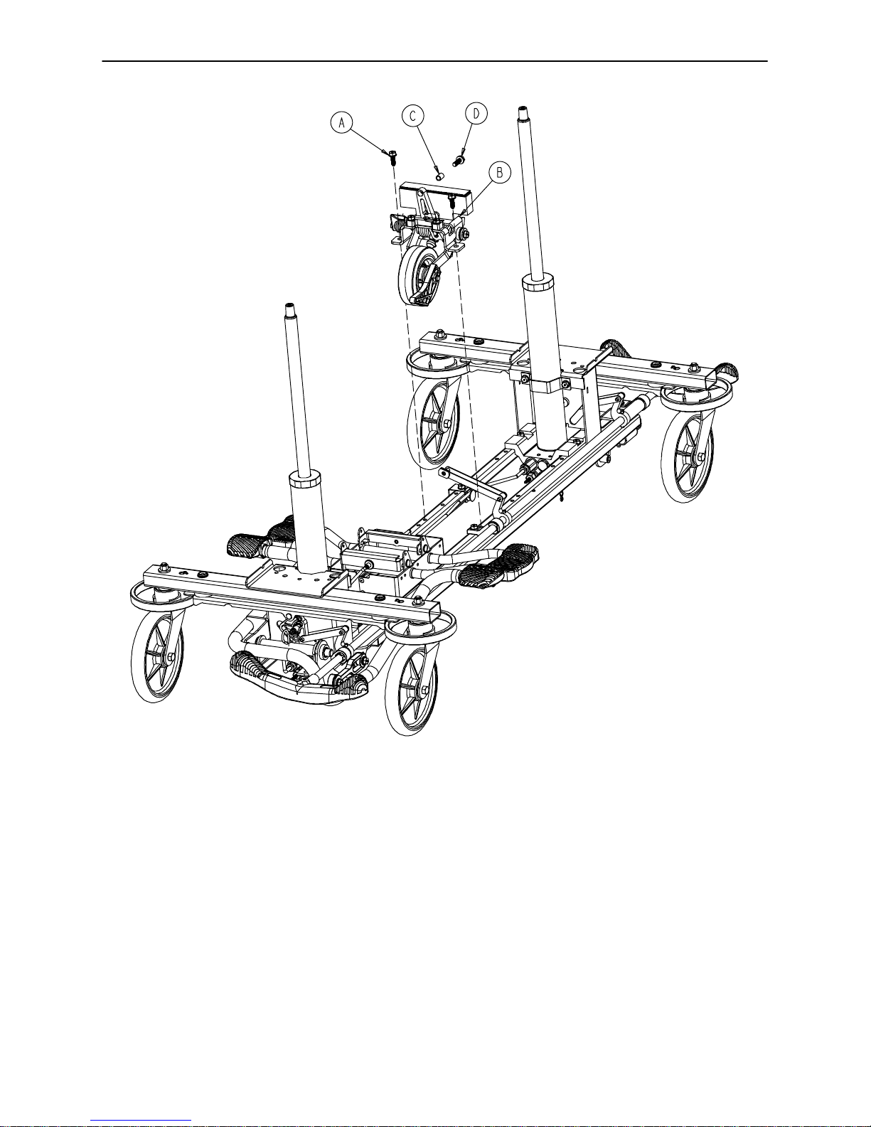
0753−006−110 Retractable Fifth Wheel Base Assembly
Item Part No. Part Name Qty.
A 0023−288−000 Hex Washer Hd. Screw 2
B(page 20) Fifth Wheel Assembly 1
C 0753−006−148 Cam Bearing 1
D 0023−305−000 Hex Hd. Cap Screw 1
19
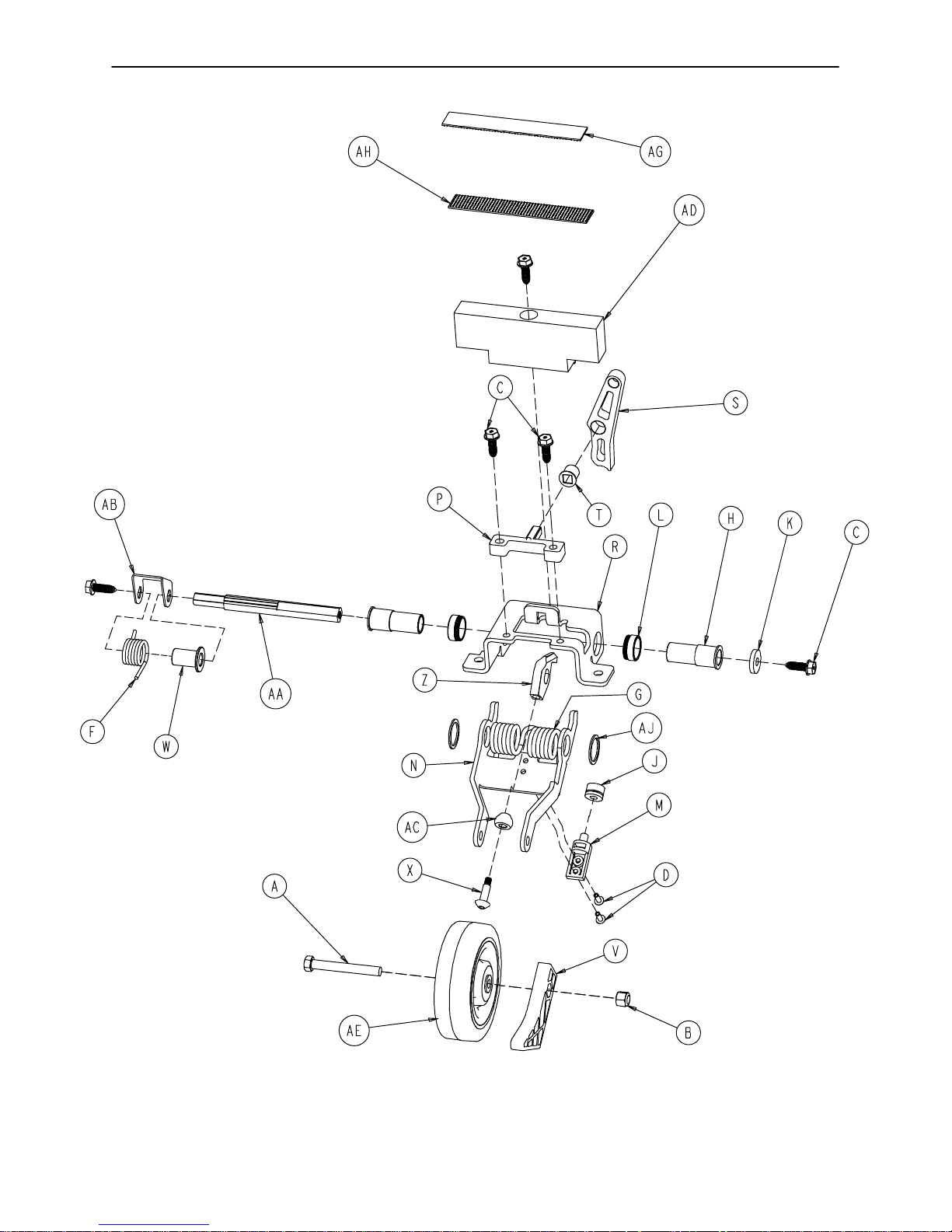
0753−006−130 Fifth Wheel Assembly
20

0753−006−130 Fifth Wheel Assembly
Item Part No. Part Name Qty.
A 0003−083−000 Hex Hd. Cap Screw 1
B 0016−035−000 Nylock Hex Nut 1
C 0023−288−000 Hex Washer Hd. Screw 5
D 0025−050−000 Rivet 2
F 0753−006−074 Torsion Spring 1
G 0753−006−075 Torsion Spring 1
H 0753−006−097 Drive Shaft Bearing 2
J 0753−006−106 Dampener 1
K 0753−006−108 Thrust Washer 1
L 0753−006−115 Bearing 2
M 0753−006−120 Bumper Mounting Pin 1
N 0753−006−126 Wheel Bracket 1
P 0753−006−133 Cam Pivot Block 1
R 0753−006−134 Fifth Wheel Mounting Bracket 1
S 0753−006−142 Fifth Wheel Cam 1
T 0753−006−143 Cam Bearing 1
V 0753−006−149 5th Wheel Ramp 1
W 0753−006−152 Spring Spacer 1
X 0753−006−153 Roller Stem 1
Z 0753−006−198 Drive Pin 1
AA 0753−006−223 Drive Shaft 1
AB 0753−006−227 Return Spring Hook 1
AC 0753−006−277 Roller 1
AD 0753−010−045 Hood Standoff 1
AE 1210−001−147 Wheel 1
AG 0753−006−280 Dual Lock 1
AH 0753−006−281 Dual Lock 1
AJ 0011−360−000 Washer 2
21
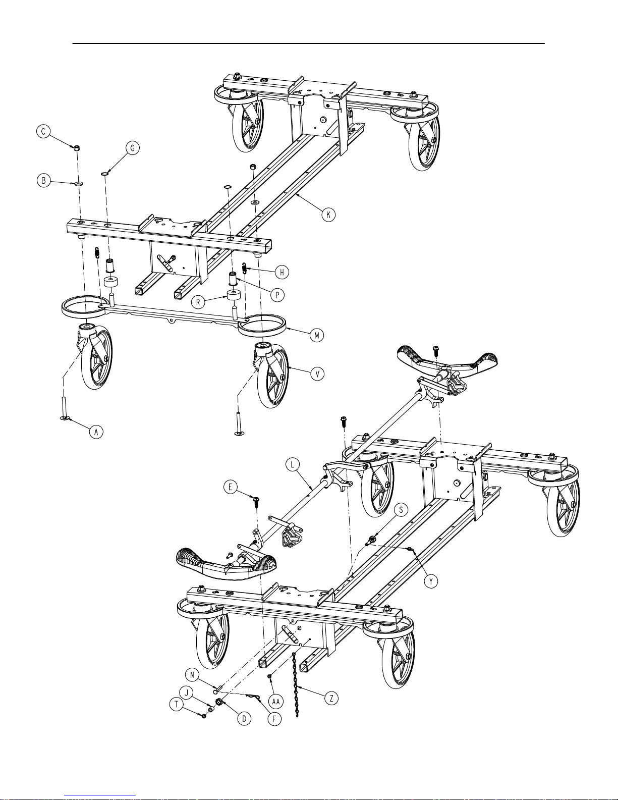
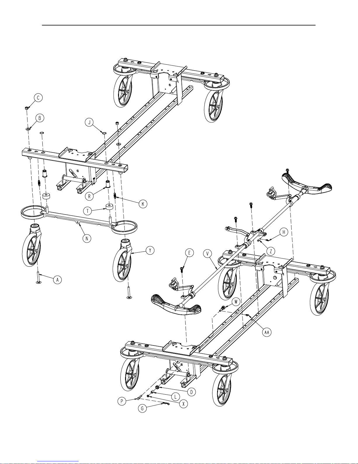
Base Assembly w/Standard Brakes (Fifth Wheel Base)
Assembly part number
0753−003−005
(reference only)
22

Base Assembly w/Standard Brakes (Fifth Wheel Base)
Item Part No. Part Name Qty.
A 0005−039−000 Step Bolt 4
B 0011−262−000 Washer 4
C 0016−035−000 Nylock Hex Nut 4
D 0016−049−000 Nylock Hex Nut 2
E 0023−288−000 Hex Washer Hd. Screw 3
F 0027−012−000 Hitch Pin 2
G 0028−037−000 External Retaining Ring 4
H 0038−439−000 Extension Spring 4
J 0081−272−000 Roller Bearing 2
K 0753−001−001 Base Frame 1
L(page 24) Brake Rod Assembly 1
M 0753−003−006 Brake Ring 2
N 0753−003−066 Clevis Pin 2
P 0753−003−079 Caster Tube Brake Pin Guide 4
R 0753−003−121 Brake Cushion 4
S 0753−003−130 Bearing Pivot Support 2
T 0753−003−131 Spacer 2
V(page 27) Caster Assembly 4
Y 0027−019−000 Rue Ring Cotter Pin 2
Z 0753−010−012 Ground Chain 1
AA 0023−025−000 H. Washer Hd. Tapping Screw 1
23

Brake Rod Assembly
Assembly part number 0753−003−001 (reference only)
Item Part No. Part Name Qty.
A 0026−067−000 Slotted Spring Pin 2
E 0753−003−004 Brake Rod Support 3
F(page 25) Drive Link Assembly 2
G 0753−003−014 Brake Rod 1
H 0753−003−015 Nyliner 3
J 0753−003−099 Butterfly “V” Pedal 2
K (page 26) Drive Link Assembly 1
M 1210−201−335 Red Brake Label 2
N 1210−201−336 Green Steer Label 2
R 0753−003−133 Retainment Spacer 1
24
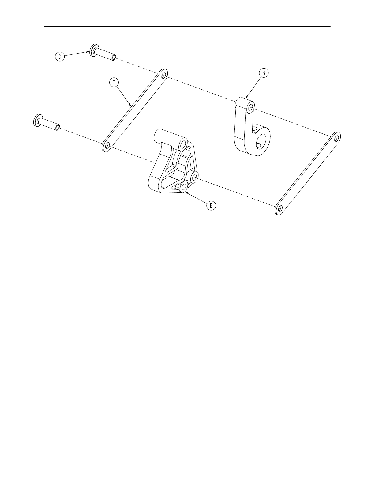
0753−003−010 Drive Link Assembly
Item Part No. Part Name Qty.
B 0753−003−011 Brake Rod Drive Link 1
C 0753−003−061 Brake Cam Drive Link 2
D 0753−003−098 Flat Hd. Semi−Tubular Rivet 2
E 0753−003−102 Brake Cam 1
25
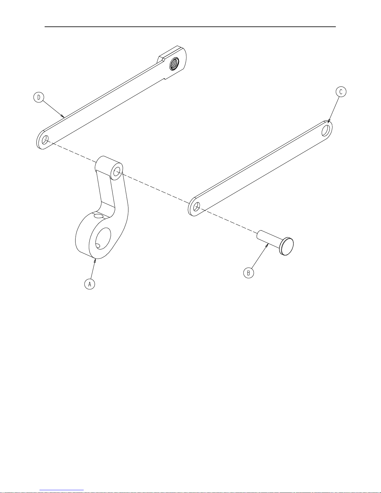
0753−006−135 Drive Link Assembly
Item Part No. Part Name Qty.
A 0753−003−011 Brake Rod Drive Link 1
B 0753−003−098 Semi−Tubular Rivet 1
C 0753−006−122 5th Wheel Cam Drive Link 1
D 0753−006−147 Fifth Wheel Drive Link 1
26
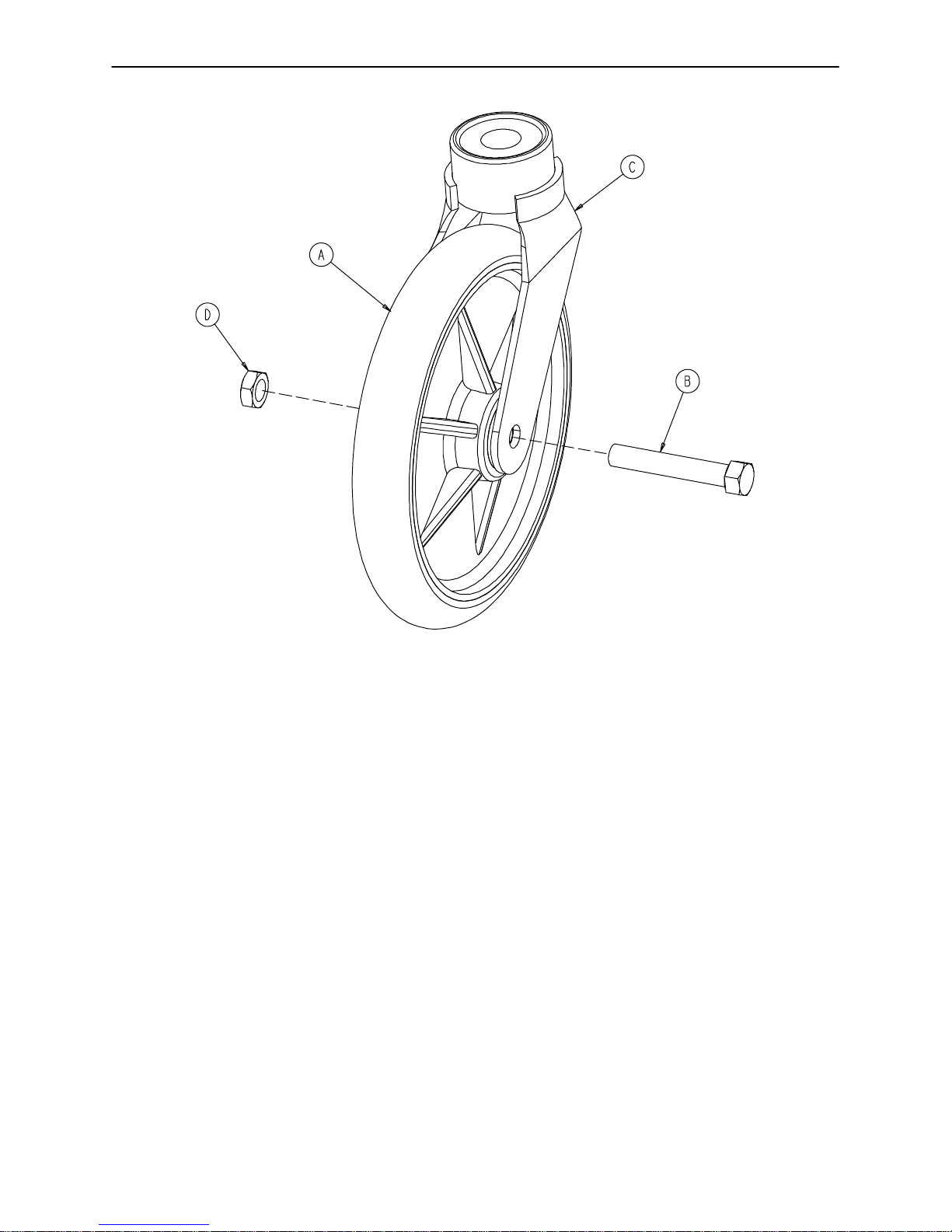
0753−010−020 8” Caster Assembly
Item Part No. Part Name Qty.
A 0715−002−025 Wheel 1
B 0003−099−000 Hex Hd. Cap Screw 1
C 0753−010−021 Caster Horn w/Bearing 1
D 0016−060−000 Centerlock Nut 1
27
Base Assembly with 4−Sided Brakes
Assembly part number 0753−003−120 (reference only)
28

Base Assembly with 4−Sided Brakes
FOOT ENDHEAD END
Item Part No. Part Name Qty. Item Part No. Part Name Qty.
A 0005−039−000 Step Bolt 4 P 0753−003−066 Clevis Pin 2
B 0011−262−000 Washer 4 R 0753−003−079 Brake Pin Guide 4
C 0016−035−000 Nylock Hex Nut 4 S (page 30) Side Brake Rod Ass’y1
D 0016−049−000 Nylock Hex Nut 2 T 0753−003−121 Brake Cushion 4
E 0023−288−000 Hex Washer Hd. Screw 8 V (page 31) Brake Rod Assembly 1
G 0027−012−000 Hitch Pin 2 W 0753−003−130 Bearing Pivot Support 2
H 0027−020−000 Rue Ring Cotter 1 X 0753−003−131 Spacer 2
J 0028−037−000 External Retaining Ring 4 Y (page 27) Caster Assembly 4
K 0038−439−000 Extension Spring 4 Z 0026−340−000 Clevis Pin 1
L 0081−272−000 Roller Bearing 2 AA 0027−019−000 Rue Ring Cotter Pin 2
M 0753−001−001 Base Weldment 1 AB 0753−010−012 Ground Chain 1
N 0753−003−006 Brake Ring Weldment 2 AC 0023−025−000 H. Washer Hd. Tap. Scr. 1
29
 Loading...