

Stryker 1004 Maintenance Manual
Medical
For parts or technical
assistance call
800 327 0770 (option 2)
Model 1004
ASC Stretcher
Maintenance
Manual
Important
Information
File in your
maintenance
records

Table of Contents
Introduction
Specifications 4. . . . . . . . . . . . . . . . . . . . . . . . . . . . . . . . . . . . . . . . . . . . . . . . . . . . . . . . . . . . . . . . . . . . . . . . . . . .
Warning / Caution / Note Definition 4. . . . . . . . . . . . . . . . . . . . . . . . . . . . . . . . . . . . . . . . . . . . . . . . . . . . . . . . .
Preventative Maintenance
Checklist 5. . . . . . . . . . . . . . . . . . . . . . . . . . . . . . . . . . . . . . . . . . . . . . . . . . . . . . . . . . . . . . . . . . . . . . . . . . . . . . . .
Cleaning 6, 7. . . . . . . . . . . . . . . . . . . . . . . . . . . . . . . . . . . . . . . . . . . . . . . . . . . . . . . . . . . . . . . . . . . . . . . . . . . . . .
Service Information
Caster Cover Installation and Removal 8. . . . . . . . . . . . . . . . . . . . . . . . . . . . . . . . . . . . . . . . . . . . . . . . . . . . . .
Caster Removal 8. . . . . . . . . . . . . . . . . . . . . . . . . . . . . . . . . . . . . . . . . . . . . . . . . . . . . . . . . . . . . . . . . . . . . . . . . .
Brake Rod Removal 9. . . . . . . . . . . . . . . . . . . . . . . . . . . . . . . . . . . . . . . . . . . . . . . . . . . . . . . . . . . . . . . . . . . . . .
Side Control Brake Rod Removal 9. . . . . . . . . . . . . . . . . . . . . . . . . . . . . . . . . . . . . . . . . . . . . . . . . . . . . . . . . . .
Release Pedal Adjustment 10. . . . . . . . . . . . . . . . . . . . . . . . . . . . . . . . . . . . . . . . . . . . . . . . . . . . . . . . . . . . . . .
Foot End Release Pedal Replacement 10. . . . . . . . . . . . . . . . . . . . . . . . . . . . . . . . . . . . . . . . . . . . . . . . . . . . .
Foot End Release Pedal Rod Removal 10. . . . . . . . . . . . . . . . . . . . . . . . . . . . . . . . . . . . . . . . . . . . . . . . . . . . .
Brake Ring Removal 11. . . . . . . . . . . . . . . . . . . . . . . . . . . . . . . . . . . . . . . . . . . . . . . . . . . . . . . . . . . . . . . . . . . . .
Fifth Wheel Assembly Removal 11. . . . . . . . . . . . . . . . . . . . . . . . . . . . . . . . . . . . . . . . . . . . . . . . . . . . . . . . . . .
Litter Top Removal 12. . . . . . . . . . . . . . . . . . . . . . . . . . . . . . . . . . . . . . . . . . . . . . . . . . . . . . . . . . . . . . . . . . . . . .
Jack Descent Rate Adjustment 12. . . . . . . . . . . . . . . . . . . . . . . . . . . . . . . . . . . . . . . . . . . . . . . . . . . . . . . . . . . .
Removal of Excess Air from the Hydraulic System 12. . . . . . . . . . . . . . . . . . . . . . . . . . . . . . . . . . . . . . . . . . .
Head End Hydraulic Jack Removal 13. . . . . . . . . . . . . . . . . . . . . . . . . . . . . . . . . . . . . . . . . . . . . . . . . . . . . . . .
Foot End Hydraulic Jack Removal 13. . . . . . . . . . . . . . . . . . . . . . . . . . . . . . . . . . . . . . . . . . . . . . . . . . . . . . . . .
Siderail Assembly Removal and Replacement 14, 15. . . . . . . . . . . . . . . . . . . . . . . . . . . . . . . . . . . . . . . . . . . .
Litter Corner Cover Replacement 15. . . . . . . . . . . . . . . . . . . . . . . . . . . . . . . . . . . . . . . . . . . . . . . . . . . . . . . . . .
Pneumatic Cylinder Replacement 16. . . . . . . . . . . . . . . . . . . . . . . . . . . . . . . . . . . . . . . . . . . . . . . . . . . . . . . . .
IV Pole Replacement 16. . . . . . . . . . . . . . . . . . . . . . . . . . . . . . . . . . . . . . . . . . . . . . . . . . . . . . . . . . . . . . . . . . . .
Quick Reference Replacement Parts List 17. . . . . . . . . . . . . . . . . . . . . . . . . . . . . . . . . . . . . . . . . . . . . . . . . . . . .

Table of Contents
Assembly Drawings and Parts Lists
Fifth Wheel Base Assembly 18. . . . . . . . . . . . . . . . . . . . . . . . . . . . . . . . . . . . . . . . . . . . . . . . . . . . . . . . . . . . . .
Fifth Wheel Assembly 19, 20. . . . . . . . . . . . . . . . . . . . . . . . . . . . . . . . . . . . . . . . . . . . . . . . . . . . . . . . . . . . . . . . .
Base Assembly with Standard Brakes 21, 22. . . . . . . . . . . . . . . . . . . . . . . . . . . . . . . . . . . . . . . . . . . . . . . . . . .
Brake Rod Assembly 23. . . . . . . . . . . . . . . . . . . . . . . . . . . . . . . . . . . . . . . . . . . . . . . . . . . . . . . . . . . . . . . . . . . .
Drive Link Assembly 24, 25. . . . . . . . . . . . . . . . . . . . . . . . . . . . . . . . . . . . . . . . . . . . . . . . . . . . . . . . . . . . . . . . . .
Caster Assembly 26. . . . . . . . . . . . . . . . . . . . . . . . . . . . . . . . . . . . . . . . . . . . . . . . . . . . . . . . . . . . . . . . . . . . . . . .
Base Assembly with Four−Sided Brakes 27, 28. . . . . . . . . . . . . . . . . . . . . . . . . . . . . . . . . . . . . . . . . . . . . . . .
Brake Rod Assembly 29. . . . . . . . . . . . . . . . . . . . . . . . . . . . . . . . . . . . . . . . . . . . . . . . . . . . . . . . . . . . . . . . . . . .
Side Control Brake Rod Assembly 30. . . . . . . . . . . . . . . . . . . . . . . . . . . . . . . . . . . . . . . . . . . . . . . . . . . . . . . . .
Base Assembly with Dual Side Hydraulics 31−33. . . . . . . . . . . . . . . . . . . . . . . . . . . . . . . . . . . . . . . . . . . . . . .
Release Pedal Assembly 34. . . . . . . . . . . . . . . . . . . . . . . . . . . . . . . . . . . . . . . . . . . . . . . . . . . . . . . . . . . . . . . . .
Pump Pedal Assembly 35. . . . . . . . . . . . . . . . . . . . . . . . . . . . . . . . . . . . . . . . . . . . . . . . . . . . . . . . . . . . . . . . . . .
Non−Constant Descent Jacks 36. . . . . . . . . . . . . . . . . . . . . . . . . . . . . . . . . . . . . . . . . . . . . . . . . . . . . . . . . . . . .
Jack Base Assembly, Non−Constant Descent Jacks 37. . . . . . . . . . . . . . . . . . . . . . . . . . . . . . . . . . . . . . . . .
Base Labeling Assembly 39−41. . . . . . . . . . . . . . . . . . . . . . . . . . . . . . . . . . . . . . . . . . . . . . . . . . . . . . . . . . . . . .
Litter Assembly 42. . . . . . . . . . . . . . . . . . . . . . . . . . . . . . . . . . . . . . . . . . . . . . . . . . . . . . . . . . . . . . . . . . . . . . . . .
Siderail Assembly 43, 44. . . . . . . . . . . . . . . . . . . . . . . . . . . . . . . . . . . . . . . . . . . . . . . . . . . . . . . . . . . . . . . . . . . .
Siderail Latch Assembly 45, 46. . . . . . . . . . . . . . . . . . . . . . . . . . . . . . . . . . . . . . . . . . . . . . . . . . . . . . . . . . . . . . .
Siderail Spindle Assembly 47, 48. . . . . . . . . . . . . . . . . . . . . . . . . . . . . . . . . . . . . . . . . . . . . . . . . . . . . . . . . . . . .
Siderail Latch Spindle Assembly 49, 50. . . . . . . . . . . . . . . . . . . . . . . . . . . . . . . . . . . . . . . . . . . . . . . . . . . . . . . .
Dual Siderail Latch Assembly 51, 52. . . . . . . . . . . . . . . . . . . . . . . . . . . . . . . . . . . . . . . . . . . . . . . . . . . . . . . . . .
Latch Assembly 53−56. . . . . . . . . . . . . . . . . . . . . . . . . . . . . . . . . . . . . . . . . . . . . . . . . . . . . . . . . . . . . . . . . . . . . .
Standard Fowler/Stationary Foot Assembly 57. . . . . . . . . . . . . . . . . . . . . . . . . . . . . . . . . . . . . . . . . . . . . . . . .
Standard Fowler Assembly 58, 59. . . . . . . . . . . . . . . . . . . . . . . . . . . . . . . . . . . . . . . . . . . . . . . . . . . . . . . . . . . .
Corner Cover Assembly 60, 61. . . . . . . . . . . . . . . . . . . . . . . . . . . . . . . . . . . . . . . . . . . . . . . . . . . . . . . . . . . . . . .
Push Handle Assembly 62. . . . . . . . . . . . . . . . . . . . . . . . . . . . . . . . . . . . . . . . . . . . . . . . . . . . . . . . . . . . . . . . . .
No Push Handle Option 63. . . . . . . . . . . . . . . . . . . . . . . . . . . . . . . . . . . . . . . . . . . . . . . . . . . . . . . . . . . . . . . . . .
IV Poles 64−70. . . . . . . . . . . . . . . . . . . . . . . . . . . . . . . . . . . . . . . . . . . . . . . . . . . . . . . . . . . . . . . . . . . . . . . . . . . .

Table of Contents
Assembly Drawings and Parts Lists (Continued)
Oxygen Bottle Holder 71. . . . . . . . . . . . . . . . . . . . . . . . . . . . . . . . . . . . . . . . . . . . . . . . . . . . . . . . . . . . . . . . . . . .
Defibrillator Tray Assembly 72. . . . . . . . . . . . . . . . . . . . . . . . . . . . . . . . . . . . . . . . . . . . . . . . . . . . . . . . . . . . . . .
Defibrillator Tray/Foot Extender/Foot Board Assembly 73. . . . . . . . . . . . . . . . . . . . . . . . . . . . . . . . . . . . . . . .
Serving Tray Assembly 74. . . . . . . . . . . . . . . . . . . . . . . . . . . . . . . . . . . . . . . . . . . . . . . . . . . . . . . . . . . . . . . . . .
Foot Board/Serving Tray Holder 75. . . . . . . . . . . . . . . . . . . . . . . . . . . . . . . . . . . . . . . . . . . . . . . . . . . . . . . . . . .
Foot Board/Chartholder Assembly 76. . . . . . . . . . . . . . . . . . . . . . . . . . . . . . . . . . . . . . . . . . . . . . . . . . . . . . . . .
Mattresses and Siderail Pads 77. . . . . . . . . . . . . . . . . . . . . . . . . . . . . . . . . . . . . . . . . . . . . . . . . . . . . . . . . . . . .
Warranty
Obtaining Parts and Service 78. . . . . . . . . . . . . . . . . . . . . . . . . . . . . . . . . . . . . . . . . . . . . . . . . . . . . . . . . . . . . .
Service Contract Coverage 78. . . . . . . . . . . . . . . . . . . . . . . . . . . . . . . . . . . . . . . . . . . . . . . . . . . . . . . . . . . . . . .
Return Authorization 79. . . . . . . . . . . . . . . . . . . . . . . . . . . . . . . . . . . . . . . . . . . . . . . . . . . . . . . . . . . . . . . . . . . . .
Freight Damage Claims 79. . . . . . . . . . . . . . . . . . . . . . . . . . . . . . . . . . . . . . . . . . . . . . . . . . . . . . . . . . . . . . . . . .

Introduction
INTRODUCTION
This manual is designed to assist you with the maintenance of the Model 1004 Stretcher. Read it thoroughly
before using the equipment or beginning any maintenance on it.
SPECIFICATIONS
Maximum Weight Capacity 500 pounds
Overall Stretcher Length 84” ( .5”)
Overall Stretcher Width (Siderails Up) 33.5” & 37” ( .5”)
Overall Stretcher Width (Siderails Down) 30.25” & 30.75” ( .5”)
Minimum / Maximum Bed Height 21.5” / 36” ( .5”)
Fowler Angle 0 to 90° ( 3°)
Trendelenburg / Reverse Trendelenburg +16 / −16 ° ( 1°)
WARNING / CAUTION / NOTE DEFINITION
The words WARNING, CAUTION and NOTE carry special meanings and should be carefully reviewed.
WARNING
Alerts the reader about a situation, which if not avoided, could result in death or serious injury. It may also
describe potential serious adverse reactions and safety hazards.
CAUTION
Alerts the reader of a potentially hazardous situation, which if not avoided, may result in minor or moderate
injury to the user or patient or damage to the equipment or other property. This includes special care necessary for the safe and effective use of the device and the care necessary to avoid damage to a device that
may occur as a result of use or misuse.
NOTE
This provides special information to make maintenance easier or important instructions clearer.
Safe Working Load
Return to Table of Contents
4

Preventative Maintenance
CHECKLIST
All fasteners secure
Siderails move and latch properly
Engage brake pedal and push on the stretcher to ensure all casters lock securely
Steer function working properly
All casters secure and swivel properly
Body restraints working properly
IV pole intact and operating properly
Fowler operating and latching properly
Trendelenburg/Reverse Trendelenburg operating properly
No rips or cracks in mattress cover
Ground chain intact
No leaks at hydraulic connections
Hydraulic jacks holding properly
Hydraulic drop rate set properly
Hydraulic oil level sufficient
Lubricate where required
Accessories and mounting hardware in good condition and working properly
Serial No. ______________ ______________ ______________
______________ ______________ ______________
Completed By:_________________________________ Date:_____________
NOTE
Preventative maintenance should be performed at a minimum of annually. A preventative maintenance program should be established for all Stryker Medical equipment. Preventative maintenance may need to be
performed more frequently based on the usage level of the product.
Back to Table of Contents
5

Cleaning
CLEANING
Model 1004 stretchers are designed to be power−washable. The unit may show some signs of oxidation or
discoloration from continuous washing. However, no degradation of the stretcher’s performance characteristics or functionality will occur due to power washing as long as the proper procedures are followed.
S Follow the cleaning solution manufacturer’s dilution recommendations exactly.
S Remove the mattress prior to washing the unit; do not wash the mattress with the stretcher.
S Position the Fowler at 45_, place the unit in full reverse T rendelenburg (foot end down), raise the siderails,
and place the I.V. poles and push handles in the up position.
S Stryker Medical recommends the standard hospital surgical cart washer for power washing Model 1004
stretchers.
S Do not replace the mattress on the stretcher until the unit is completely dry.
S Before returning the unit to service, verify all labels are intact, verify the brake/steer pedal locks properly
in both positions and check all components for proper lubrication.
DO NOT STEAM CLEAN THE UNIT. Use a maximum water temperature of 180_F/82_C. Maximum air dry
temperature (cart washers) is 240_F/115_C. Water pressure − 1500 psi/103.5 bar. If a hand held wand is
being used to wash the unit, the pressure nozzle must be kept a minimum of 24 inches/.61m from the unit.
Stretchers must have maintenance performed after a minimum of every fifth washing. Refer to the maintenance manual for specific lubrication instructions.
Failure to comply with these instructions may invalidate any/all warranties.
Do not use abrasive cleaners to clean the display enclosure for the optional scale system. Do not allow cleaning solutions or other fluids to pool on the display unit. Wipe dry all surfaces after spills or cleaning.
Back to Table of Contents
6

Cleaning
CLEANING (CONTINUED)
Hand wash all surfaces of the stretcher with warm water and mild detergent. DRY THOROUGHLY. Do n o t
steam clean, pressure wash, hose off or ultrasonically clean. Using these methods of cleaning is not recommended and may void this product’s warranty.
Suggested cleaners for stretcher surfaces:
Quaternary Cleaners (active ingredient − ammonium chloride)
Phenolic Cleaners (active ingredient − o−phenylphenol)
Chlorinated Bleach Solution (5.25% − less than 1 part bleach to 100 parts water)
Avoid oversaturation and ensure the product does not stay wet longer than the chemical manufacturer ’s
guidelines for proper disinfecting.
CAUTION
SOME CLEANING PRODUCTS ARE CORROSIVE IN NATURE AND MAY CAUSE DAMAGE TO THE
PRODUCT IF USED IMPROPERLY. If the products described above are used to clean Stryker patient care
equipment, measures must be taken to insure the beds are wiped with clean water and thoroughly dried following cleaning. Failure to properly rinse and dry the beds will leave a corrosive residue on the surface of
the bed, possibly causing premature corrosion of critical components. Failure to follow the above directions
when using these types of cleaners may void this product’s warranty.
For mattress cleaning instructions, please see the tag on the mattress, or contact the mattress manufacturer.
Clean Velcro AFTER EACH USE. Saturate Velcro with disinfectant and allow disinfectant to evaporate.
(Appropriate disinfectant for nylon Velcro should be determined by the hospital.
Return to Table of Contents
7
Service Information
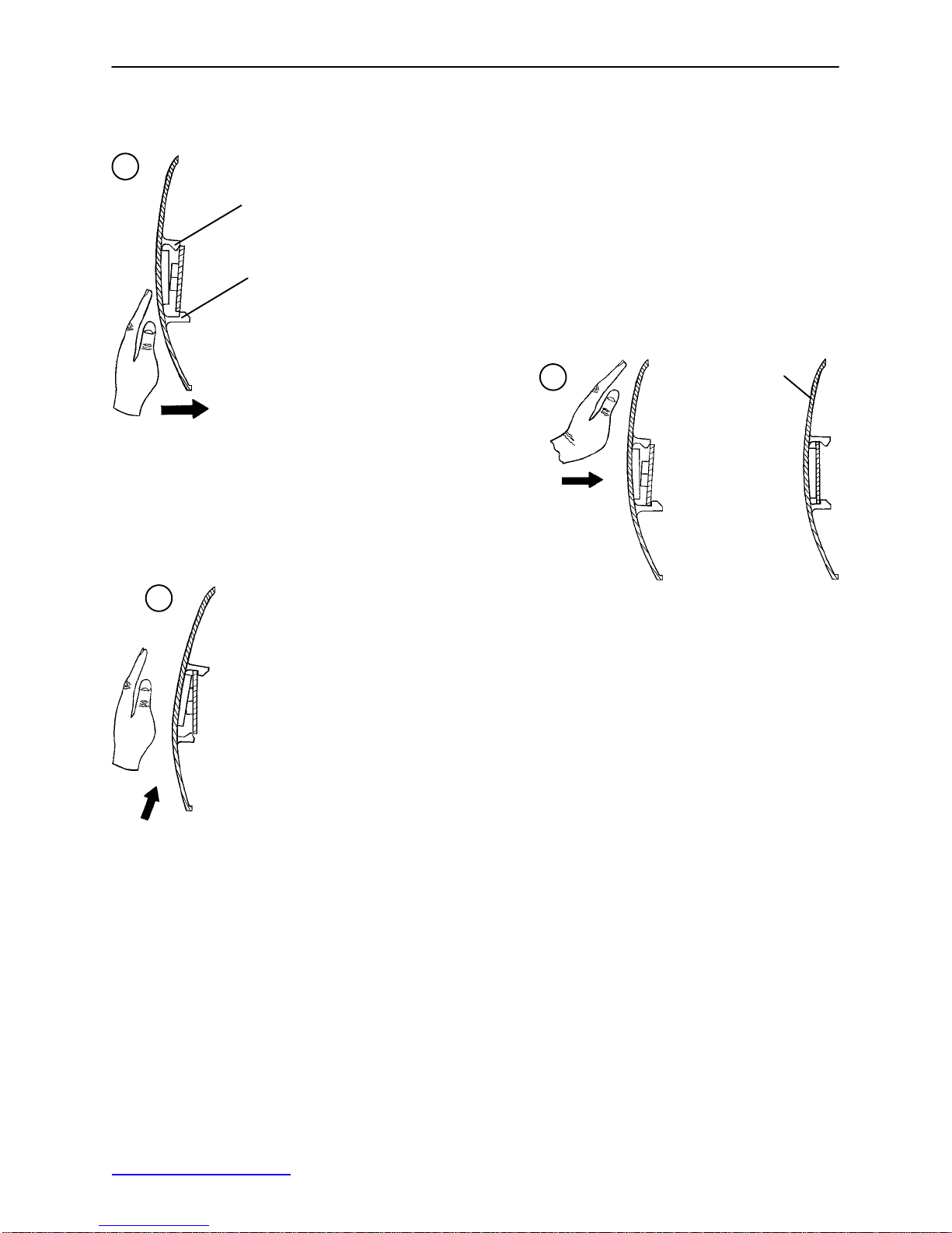
CASTER COVER INSTALLATION AND REMOVAL
1.
Double Prongs
Looking through the larger of the two side cut−outs,
align the cover with the axle nut or bolt head, as shown.
Single Prong
Push down on the opposite side of the cover until the
single prong engages the caster horn.
3.
Top View (Cut−Away)
Push on the cover with your palm until
the double prongs engage.
To remove the wheel cover, insert a large screwdriver into the cut−out
in the side of the wheel cover and into the space between the double
prongs. Pry up the cover to disengage the double prongs and push
sharply upward to disengage the single prong.
Top View (Cut−Away)
2.
Properly Attached
Cover
Top View (Cut−Away)
CASTER REMOVAL
Required Tools:
9/16” Open End Wrench
1. Remove the caster cover.
2. While keeping pressure on the caster bolt with your index finger, use a 9/16” open end wrench to remove
the nylock hex nut on top of the caster assembly.
3. Using the brake ring, lift up on the base assembly and pull the caster assembly down to remove it.
4. Reverse steps 1−3 to install the new caster.
Back to Table of Contents
8

Service Information
BRAKE ROD REMOVAL
Required Tools:
Hammer 7/32” Punch String or Bungee Cords
1. Pump the litter up to full height.
2. Lift the base hood and support it from the litter using string or bungee cords.
3. Remove the hex head cap screws connecting the brake rod supports to the base frame.
4. Remove the bolt connecting the drive link assembly to the fifth wheel cam.
5. Remove the rue ring cotter and clevis pin connecting the rod end link to the side control link.
6. Remove the rue ring cotter connecting the drive link assembly to the bearing pivot support on the base
frame (under the brake ring weldment).
7. Remove the three hex washer head screws holding the brake rod assembly to the base frame.
8. Remove the slotted spring pins connecting the butterfly “V” pedals, drive link assemblies and side control
link to the brake rod.
9. Reverse steps 1−8 to reinstall the brake rod. When reinstalling the brake rod supports, torque the hex
head cap screws to 12−15 ft.−lbs.
CAUTION
When reattaching the brake rod assembly to the base frame, set the torque specs no higher than 15 ft.−lbs.
or damage could occur to the bolts.
SIDE CONTROL BRAKE ROD REMOVAL
Required Tools:
1. Pump the litter up to full height.
2. Lift the base hood and support it from the litter using string or bungee cords.
3. Remove the rue ring cotter and clevis pin connecting the rod end link to the side control link.
4. Remove the four bolts holding the brake rod assembly to the base frame and remove the entire assembly .
5. Using a hammer and 7/32” punch, drive the slotted spring pin out of the butterfly “V” pedal on the patient’s
left side and remove the pedal,
6. Using a hammer and 7/32” punch, drive the slotted spring pin out of the hard stop in the center of the
support weldment.
7. Using a hammer and 7/32” punch, drive out the slotted spring pin connecting the side control link to the
side control brake rod on the patient’s right side.
8. Pull o n the butterfly “V” pedal on the patient’s right side to remove the side control brake rod from the base.
Hammer 7/32” Punch Needle Nose Pliers String or Bungee Cords
9. Reverse steps 1−8 to reinstall the brake rod. When reinstalling the assembly, torque the hex head cap
screws to 12−15 ft.−lbs.
CAUTION
When reattaching the brake rod assembly to the base frame, set the torque specs no higher than 15 ft.−lbs.
or damage could occur to the bolts.
Back to Table of Contents
9

Service Information
RELEASE PEDAL ADJUSTMENT
1. Manually disengage the release pedal swivel (item J on page 32) from the release pedal assembly.
2. To increase the release rod engagement with the release valve, turn the release pedal swivel clockwise
on the threaded release rod.
3. To decrease the release rod engagement with the release valve, turn the release pedal swivel counterclockwise on the threaded release rod.
NOTE
If the pedal swivel assembly is threaded too far onto the release rod, the release valve will be partially activated and the jack will drift.
FOOT END RELEASE PEDAL REPLACEMENT
Required Tools:
1. Apply the stretcher brakes.
2. Disconnect the release pedal return springs from the foot end release pedals.
3. Remove the rue ring cotters and the clevis pins connecting the foot end release pedals to the mounting
bracket.
4. Rotate the pedals upward.
5. Remove the rue ring cotters connecting the head end and foot end release rods to the foot end release
pedals and remove the pedals.
6. Reverse steps 2−5 to install the new pedals.
Needle Nose Pliers
FOOT END RELEASE PEDAL ROD REMOVAL
Required Tools:
1. Remove the foot end release pedal (see procedure above).
2. Remove the snap in nyliners holding the foot end pedal release rods in the pedal mounting bracket.
3. Unsnap the foot end pedal release rods from the white plastic release rod brackets.
Needle Nose Pliers
4. Dislodge the side control release pedal swivels from the studs on the side control release pedal weldments.
5. Remove the foot end pedal release rods.
6. Reverse steps 1−5 to reinstall the pedal rods.
Back to Table of Contents
10

Service Information
BRAKE RING REMOVAL
Required Tools:
9/16” Socket w/Extension 3/8” Drive Ratchet Needle−Nose Pliers String or Bungee Cord
1. Pump the litter up to full height.
2. Lift the base hood and support it from the litter using string or bungee cords.
3. Using needle−nose pliers, unhook the extension springs from the top of the base caster tubes.
4. Remove the plastic caster covers.
5. While putting pressure on the caster carriage bolt, use a 9/16” socket and a 3/8” drive ratchet to remove
the caster nut on both sides of the stretcher.
6. Remove the casters.
7. Remove the brake rod (see procedure).
8. Remove the cotter pin from the clevis pin in the center of the brake ring weldment.
9. Remove the cotter pin from the bearing pivot support.
10. Remove the 3/4” nylock hex nut from the bearing pivot support.
11. Remove the drive link assembly.
12. Pull the brake ring down and out away from the stretcher base frame.
13. Reverse steps 1−12 to reinstall the brake ring.
FIFTH WHEEL ASSEMBLY REMOVAL
Required Tools:
1/2” Socket 3/8” Drive Ratchet
1. Using a 1/2” socket and 3/8” drive ratchet, remove the 1/2” bolt holding the fifth wheel cam drive link and
fifth wheel drive link to the fifth wheel cam.
2. Remove the two 1/2” bolts holding the fifth wheel mounting bracket to the base frame weldment.
3. Remove the fifth wheel assembly.
4. Reverse steps 1 and 2 to reinstall the fifth wheel. When reinstalling the assembly, torque the hex head
cap screws to 12−15 ft.−lbs.
CAUTION
When reattaching the fifth wheel assembly to the base frame, set the torque specs no higher than 15 ft.−lbs.
or damage could occur to the bolts.
Back to Table of Contents
11

LITTER TOP REMOVAL
Service Information
Required Tools:
1. Using the foot pedal, pump up the litter top to full height.
2. Remove the stretcher mattress
3. Using a 1/2” socket, and a 3/8” drive ratchet, remove the truss head screws holding the jack support tubes
to the jack shafts.
4. Thread a 7/16−20 fine thread bolt far enough into the top of the jack supports to separate the litter top
from the jack shaft.
5. With the assistance of another person, lift the litter straight up to remove it from the jack shafts and set
it aside.
1/2” Socket w/Extension 3/8” Drive Ratchet Standard Screwdriver
JACK DESCENT RATE ADJUSTMENT
Required Tools:
Screwdriver Bungee Cords (or equivalent)
Adjustment Procedure:
1. Pump the litter up to full height.
2. Lift the base hood, separating the hood from the base frame. Support the hood from the litter using bungee cords so it is out of the way.
3. The descent rate needle valve is located on the base of the jack. Turning the needle valve clockwise,
with a screwdriver, will decrease the rate of descent. Turning it counterclockwise will increase the rate
of descent.
NOTE
The larger percentage of a patient’s weight is located in the torso area. Adjust descent rate accordingly.
4. Remove the bungee cords supporting the base hood and secure the hood to the base frame.
NOTE
The jack descent rate is preset at the factory and adjustment is not recommended.
REMOVAL OF EXCESS AIR (VACUUM) FROM THE HYDRAULIC SYSTEM
1. Verify all hydraulic linkages are secure and operating properly.
2. Using the pump pedal, actuate the system several times to force the air through the system. The jack
should now raise properly.
Back to Table of Contents
12

Service Information
HEAD END HYDRAULIC JACK REMOVAL
Required Tools:
1. Remove the litter top from the stretcher (see page 12).
2. Using a 1/2” socket with extension and a 3/8” drive ratchet, remove the two hex head screws holding the
jack base to the stretcher base frame.
3. Remove the two hex head screws holding the jack reservoir clamp to the base frame and remove the
clamps.
4. Lift straight up on the pump connecting rod and disconnect the pump piston from the connecting rod.
5. Disconnect the pump pedal swivel from the release pedal mounting plate.
6. Remove the head end release rod from the release valve assembly.
7. Using a 1/2” socket with extension and a 3/8” drive ratchet, remove the two hex head screws holding the
jack base to the stretcher base frame.
8. Lift out the jack assembly.
9. To reinstall the jack, install the bolts on the jack and reservoir clamp but do not tighten them fully.
10. Reinstall the pump connecting rod and release rod.
11. Depress the pump pedal fully (to the floor). This will properly locate the jack onto the base frame.
12. Tighten the bolts on the jack and reservoir clamp.
13. Pump up the litter and apply weight to verify the jacks hold and do not drift.
1/2” Socket w/Extension 3/8” Drive Ratchet
NOTE
The jack descent rate is preset at the factory and adjustment is not recommended.
FOOT END HYDRAULIC JACK REMOVAL (BASE WITH DUAL CONTROLS)
Required Tools:
1/2” Socket 3/8” Drive Ratchet Pliers
1. Remove the litter top from the stretcher (see page 12).
2. Lift the base hood off the base frame.
3. Remove the two hex washer head screws and washers connecting the pump pedal link to the foot end
pump pedal assembly and pump connecting rod.
4. Remove the foot end release rod from the release valve on the jack assembly by dislodging the release
pedal swivel from the pins on the release pedal weldment.
5. Dislodge the jack pump piston from the pump connecting rod.
6. Remove the two hex washer head screws holding the reservoir clamp.
7. Remove the jack assembly.
8. Reverse steps 1−7 to install the new jack.
NOTE
The jack descent rate is preset at the factory and adjustment is not recommended.
Back to Table of Contents
13

Service Information
SIDERAIL ASSEMBLY REMOVAL AND REPLACEMENT
Required Tools:
1/2” Socket 3/8” Drive Ratchet Torque Wrench
1. Raise the Fowler. Remove the slider board from the storage tray.
2. Pull up on the monitor/utility tray to remove it from the litter frame.
3. If you’re replacing the left siderail assembly, use a 1/2” socket and 3/8” drive ratchet, remove the four hex
head cap screws holding the O2 holder bracket to the litter frame and remove the O2 holder.
4. Remove the four hex head cap screws holding the slider board tray to the litter frame.
5. Remove the rue ring cotter holding the Fowler pivot bolt and remove the pivot bolt.
6. Remove the two bolts holding the frame tie weldment.
7. Remove the plastic litter corner covers (see page 15).
8. Remove the two bolts holding the Fowler drop seat bracket.
9. Remove the six bolts holding the siderail to the head end and foot end litter weldments.
10. Carefully remove the siderail assembly.
11. Slide the side of the stretcher with the remaining siderail next to a wall to brace it or support it with bungee
cords before starting to install the new siderail.
12. Lift the new siderail into position.
13. Insert the foot end jack support into the hole in the support tube bracket on the siderail. Insert the head
end jack support tube into the slot in the Trend slide block.
14. Install the three bolts at the foot end litter weldment. Tighten to 13 foot−pounds torque.
15. Install the two bolts at the frame tie weldment.
16. Install the three bolts at the head end litter weldment.
17. Install the two bolts at the Fowler drop seat bracket. Tighten to 13 foot−pounds torque.
18. Install the litter corner covers, the slider board tray, the O2 holder and the monitor tray.
Back to Table of Contents
14
Service Information
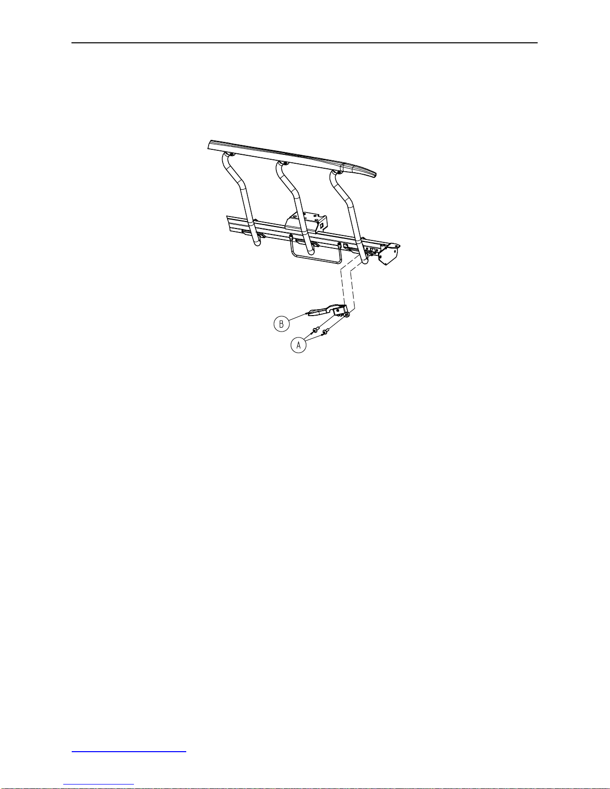
SIDERAIL LATCH REPLACEMENT
Required Tools:
3/8” Drive Ratchet T40 Torx Bit
1. Using the foot pedal, raise the litter to maximum height.
2. Remove the two bolts (A) holding the siderail latch (B) to the litter frame and discard the bolts and latch.
3. Using the new bolts provided in the kit, install the new siderail latch.
4. Verify proper latching and unlatching of the siderail before returning the stretcher to service.
LITTER CORNER COVER REPLACEMENT
Required Tools:
Drill w/ 1/4” Bit T25 Torx Utility Knife
1. Drill out the rivet holding the IV pole and/or push handle in the socket and remove the IV pole/handle from
the socket.
2. Using a utility knife, pry off the three hole plugs in the top of the cover.
3. Using a T25 Torx, remove the 3 screws holding the top and bottom covers together and pull apart the
cover.
4. Reverse to install the new cover.
Back to Table of Contents
15

Service Information
PNEUMATIC CYLINDER REPLACEMENT
Required Tools:
3/8” Drive Ratchet 3/8” Socket Needle Nose Pliers
1. Using a 3/8 drive ratchet and 3/8” socket, remove the bolt connecting the pneumatic cylinder to the Fowler
weldment. Save the bushing and spacers to use with the new cylinder.
2. Turn the cylinder counterclockwise to thread it out of the gas spring trip on the litter frame tie weldment.
3. Pull the Fowler cable off the gas spring trip.
4. Using needle nose pliers, pull off the rue ring cotter and remove the clevis pin holding the gas spring trip
to the litter frame tie weldment.
5. Depress the new cylinder fully.
6. Thread the cylinder into the gas spring trip until it stops.
CAUTION
Do not use a wrench, pliers, etc. to grip the cylinder. Gripping the cylinder too tightly may mar the surface
of the cylinder and cause damage.
NOTE
When reinstalling the bolt and the clevis pin, use the holes in each bracket nearest the foot end of the stretcher
for a drop seat Fowler and the holes in each bracket nearest the head end of the stretcher for a standard
Fowler.
7. Replace the bolt, bushing and spacers holding the cylinder to the Fowler weldment. The bolt will only
thread through the bracket from the patient right side.
8. Lift the Fowler slightly until the parts are aligned and replace the clevis pin and the rue ring cotter to connect the gas spring trip to the litter frame tie weldment.
9. Reconnect the Fowler cable.
IV POLE REPLACEMENT
Required Tools:
T25 Torx Utility Knife 1/2” Socket
3/8” Drive Ratchet
1. Using a utility knife, pry off the three hole plugs in the top of the litter corner cover.
2. Using a T25 Torx, remove the 3 screws holding the top and bottom covers together and pull apart the
cover.
3. Remove the bolt holding the IV pole socket to the litter frame and remove the IV pole.
4. Reverse to install the new IV pole and reinstall the litter corner cover.
Back to Table of Contents
16

Quick Reference Replacement Parts List
NOTE
The parts and accessories listed on this page are all currently available for purchase. Some of the parts identified on the assembly drawings pages in this manual may not be individually available for purchase. Please
call Stryker Customer Service at 1−800−327−0770 for availability and pricing.
PART NAME PART NUMBER
Caster Assembly (1 complete) 0753−010−020. . . . . . . . . . . . . . . . . . . . . . . . . . . . . . . . . . . . . . . . . . . . . . . .
Hydraulic Jack Assembly, Non Constant Descent 0753−002−080. . . . . . . . . . . . . . . . . . . . . . . . . . . . . . . .
IV Pole, Standard Removable 0390−025−000. . . . . . . . . . . . . . . . . . . . . . . . . . . . . . . . . . . . . . . . . . . . . . . .
Mattress, 4” x 30”, Echo 0785−034−343. . . . . . . . . . . . . . . . . . . . . . . . . . . . . . . . . . . . . . . . . . . . . . . . . . . . . .
Mattress, 3” x 30”, Enhanced 0785−034−313. . . . . . . . . . . . . . . . . . . . . . . . . . . . . . . . . . . . . . . . . . . . . . . . .
Mattress, 4” x 30”, Enhanced 0785−034−323. . . . . . . . . . . . . . . . . . . . . . . . . . . . . . . . . . . . . . . . . . . . . . . . .
Mattress, 4” x 30”, Ultra Comfort 0785−034−303. . . . . . . . . . . . . . . . . . . . . . . . . . . . . . . . . . . . . . . . . . . . . .
Mattress, 5” x 30”, Ultra Comfort 0785−034−333. . . . . . . . . . . . . . . . . . . . . . . . . . . . . . . . . . . . . . . . . . . . . .
Paint, Touch−Up, Gloss Black, Bottle w/Brush 7000−001−322. . . . . . . . . . . . . . . . . . . . . . . . . . . . . . . . . . .
Paint, Touch−Up, Gloss Black, Spray Can 7000−001−319. . . . . . . . . . . . . . . . . . . . . . . . . . . . . . . . . . . . . .
Paint, Touch−Up, Gray, Bottle w/Brush 7000−001−320. . . . . . . . . . . . . . . . . . . . . . . . . . . . . . . . . . . . . . . . .
Paint, Touch−Up, Gray, Spray Can 7000−001−317. . . . . . . . . . . . . . . . . . . . . . . . . . . . . . . . . . . . . . . . . . . . .
Pneumatic Fowler Cylinder 0360−031−077. . . . . . . . . . . . . . . . . . . . . . . . . . . . . . . . . . . . . . . . . . . . . . . . . . .
Restraint Strap Package 0785−045−010. . . . . . . . . . . . . . . . . . . . . . . . . . . . . . . . . . . . . . . . . . . . . . . . . . . . .
Restraint Strap, Ankle 0785−045−020. . . . . . . . . . . . . . . . . . . . . . . . . . . . . . . . . . . . . . . . . . . . . . . . . . . . . . . .
Restraint Straps, Body 0785−045−015. . . . . . . . . . . . . . . . . . . . . . . . . . . . . . . . . . . . . . . . . . . . . . . . . . . . . . .
Restraint Strap, Wrist 0946−044−100. . . . . . . . . . . . . . . . . . . . . . . . . . . . . . . . . . . . . . . . . . . . . . . . . . . . . . . .
Siderail Latch Kit 0785−700−005. . . . . . . . . . . . . . . . . . . . . . . . . . . . . . . . . . . . . . . . . . . . . . . . . . . . . . . . . . . .
Back to Table of Contents
17
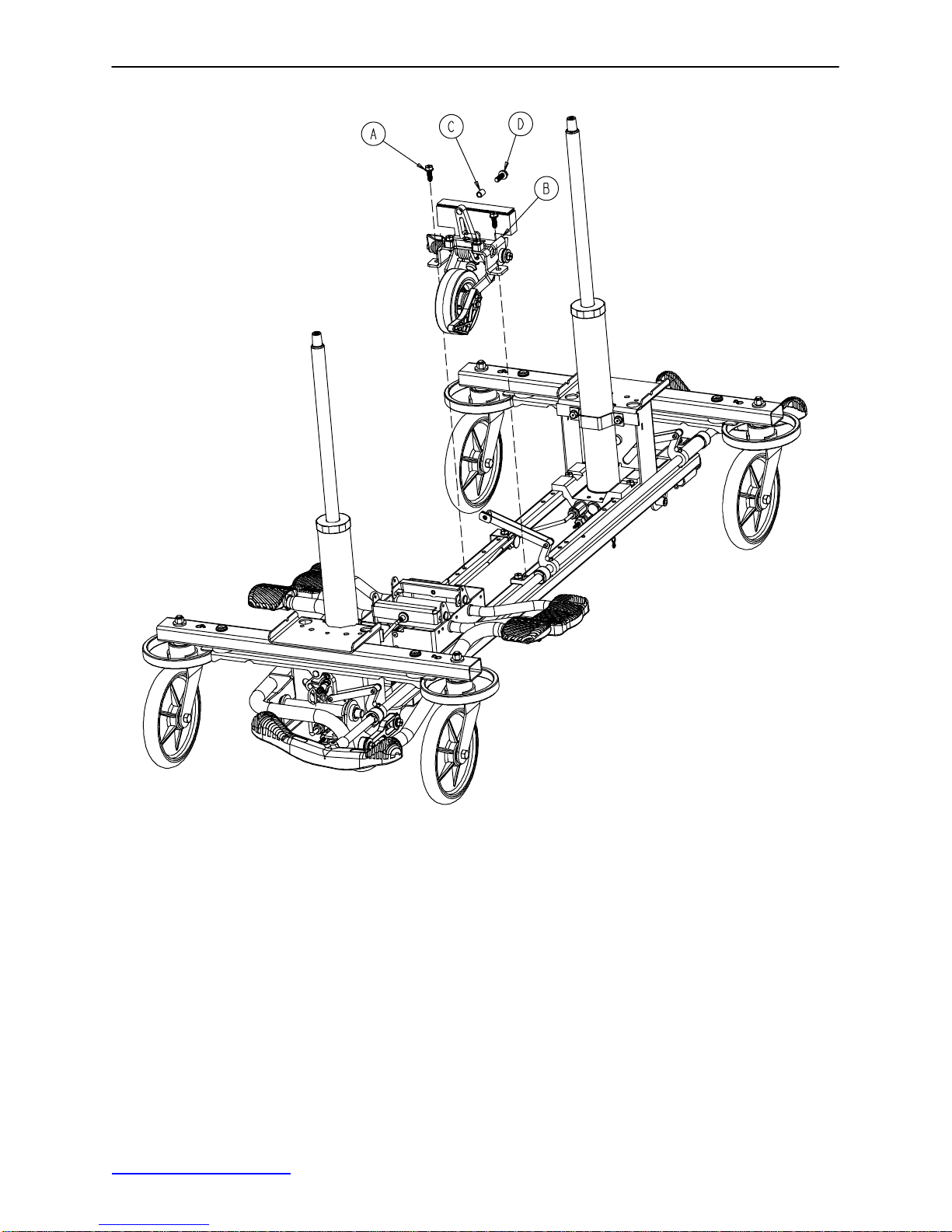
0753−006−110 Retractable Fifth Wheel Base Assembly
Item Part No. Part Name Qty.
A 0023−288−000 Hex Washer Hd. Screw 2
B(page 19) Fifth Wheel Assembly 1
C 0753−006−148 Cam Bearing 1
D 0023−305−000 Hex Hd. Cap Screw 1
Back to Table of Contents
18
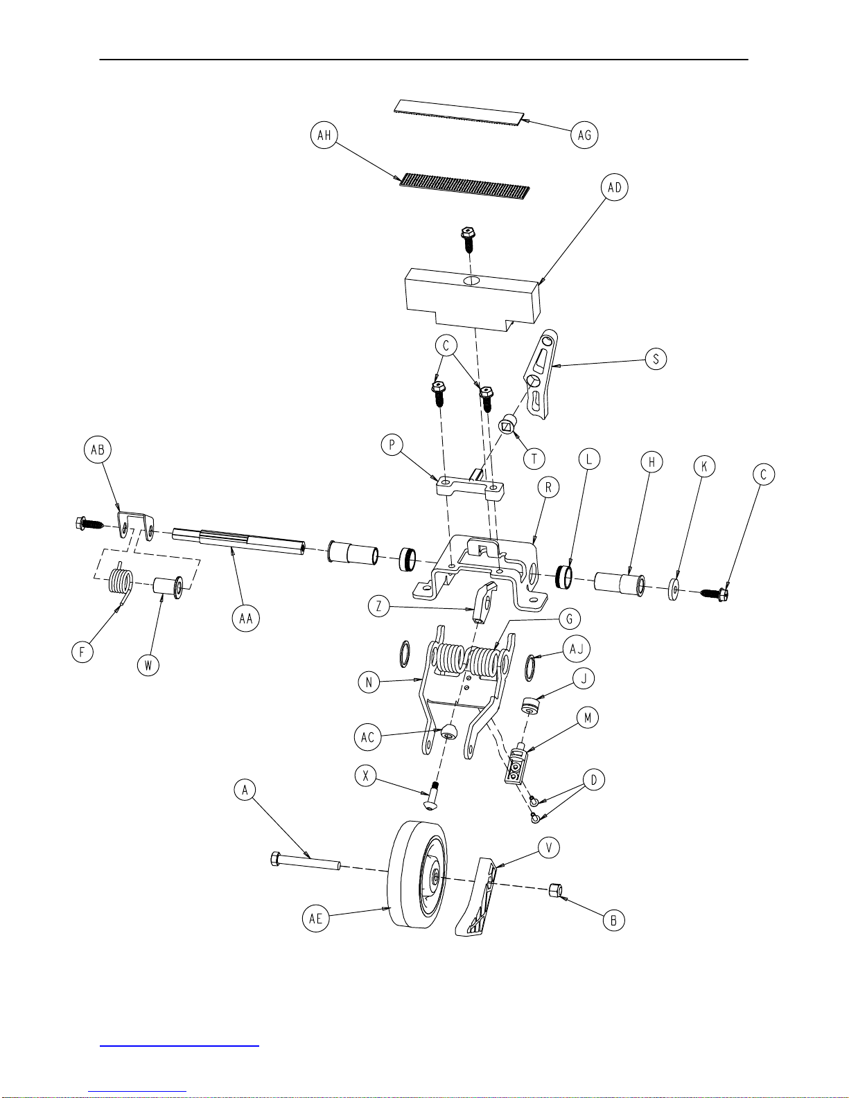
0753−006−130 Fifth Wheel Assembly
Back to Table of Contents
19

0753−006−130 Fifth Wheel Assembly
Item Part No. Part Name Qty.
A 0003−083−000 Hex Hd. Cap Screw 1
B 0016−035−000 Nylock Hex Nut 1
C 0023−288−000 Hex Washer Hd. Screw 5
D 0025−050−000 Rivet 2
F 0753−006−074 Torsion Spring 1
G 0753−006−075 Torsion Spring 1
H 0753−006−097 Drive Shaft Bearing 2
J 0753−006−106 Dampener 1
K 0753−006−108 Thrust Washer 1
L 0753−006−115 Bearing 2
M 0753−006−120 Bumper Mounting Pin 1
N 0753−006−126 Wheel Bracket 1
P 0753−006−133 Cam Pivot Block 1
R 0753−006−134 Fifth Wheel Mounting Bracket 1
S 0753−006−142 Fifth Wheel Cam 1
T 0753−006−143 Cam Bearing 1
V 0753−006−149 5th Wheel Ramp 1
W 0753−006−152 Spring Spacer 1
X 0753−006−153 Roller Stem 1
Z 0753−006−198 Drive Pin 1
AA 0753−006−223 Drive Shaft 1
AB 0753−006−227 Return Spring Hook 1
AC 0753−006−277 Roller 1
AD 0753−010−045 Hood Standoff 1
AE 1210−001−147 Wheel 1
AG 0753−006−280 Dual Lock 1
AH 0753−006−281 Dual Lock 1
AJ 0011−360−000 Washer 2
Back to Table of Contents
20
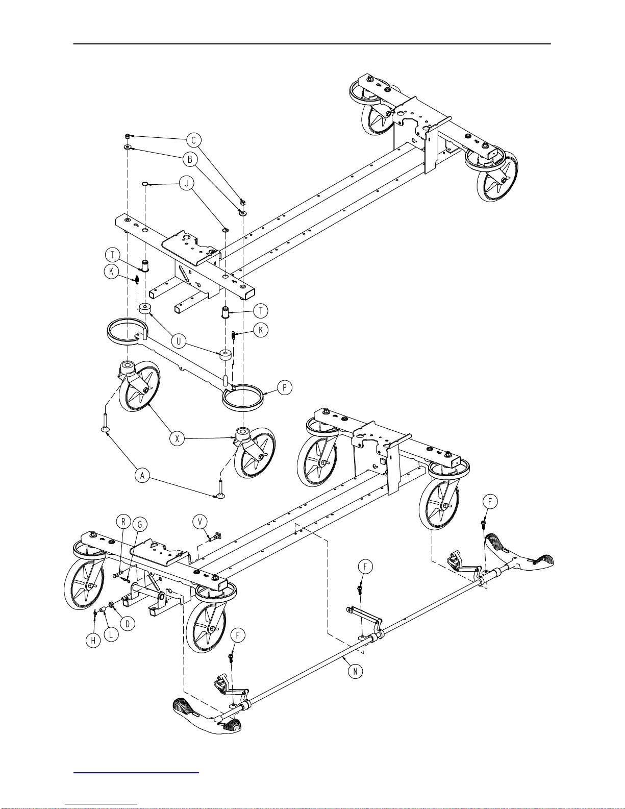
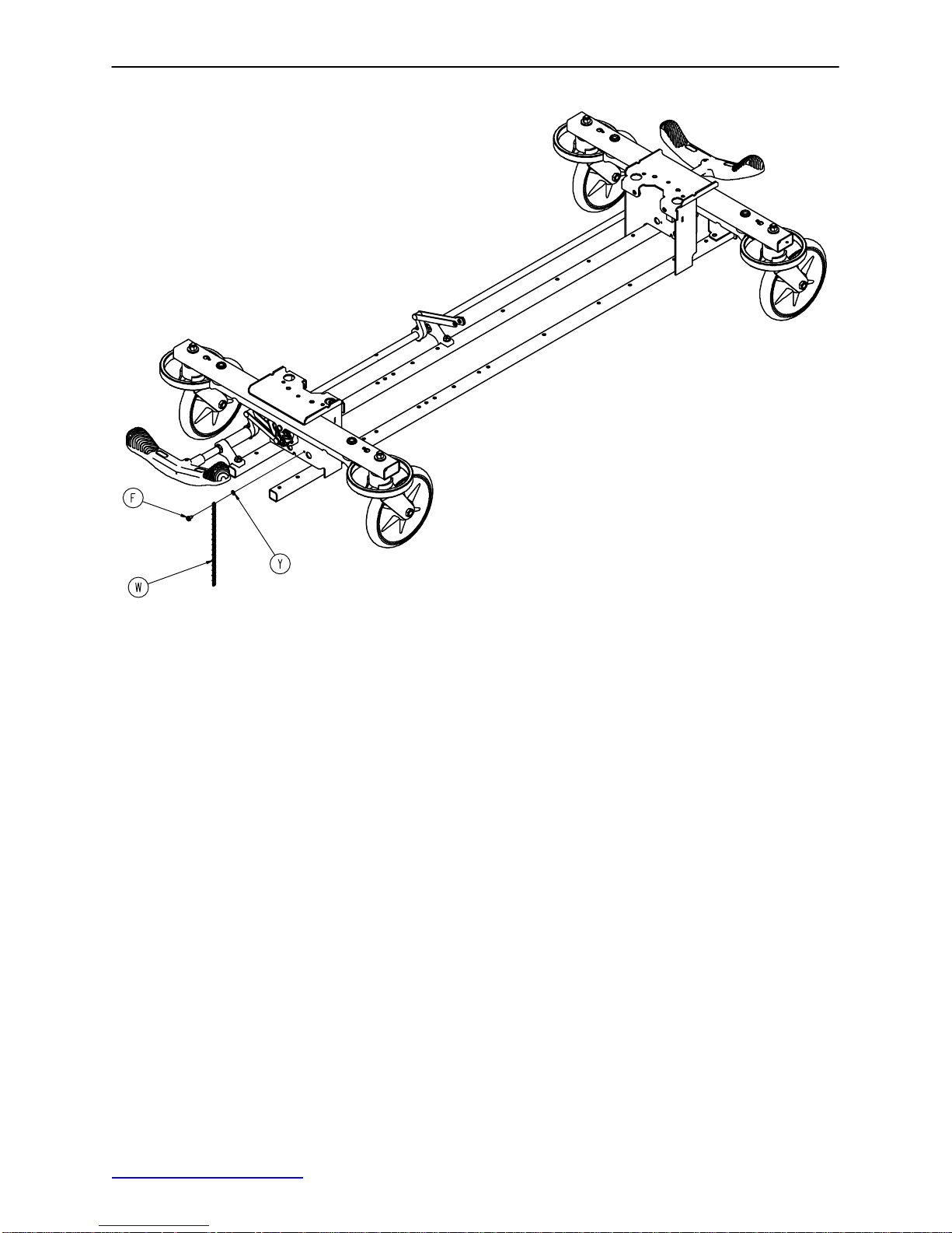
Base Assembly w/Standard Brakes (Fifth Wheel Base)
Assembly part number
0753−003−105
(reference only)
Return to Table of Contents
21
Base Assembly w/Standard Brakes (Fifth Wheel Base)
Item Part No. Part Name Qty.
A 0005−044−000 Step Bolt 4
B 0011−262−000 Washer 4
C 0016−035−000 Nylock Hex Nut 4
D 0016−049−000 Nylock Hex Nut 2
E 0023−288−000 Hex Washer Hd. Screw 1
F 0003−364−000 Hex Washer Hd. Screw 1
G 0027−012−000 Hitch Pin 2
H 0027−022−000 Rue Ring Cotter 2
J 0028−037−000 External Retaining Ring 4
K 0038−439−000 Extension Spring 4
L 0081−037−000 Plane Bearing 2
M 0753−001−001 Base Frame 1
N(page 23) Brake Rod Assembly 1
P 0753−003−006 Brake Ring 2
R 0753−003−066 Clevis Pin 2
T 0753−003−079 Caster Tube Brake Pin Guide 4
U 0753−003−121 Brake Cushion 4
V 0753−003−230 Bearing Pivot Support 2
W 3001−200−052 Ground Chain 1
X(page 26) Caster Assembly 4
Y 0013−018−000 External Tooth Lock Washer 1
Return to Table of Contents
22
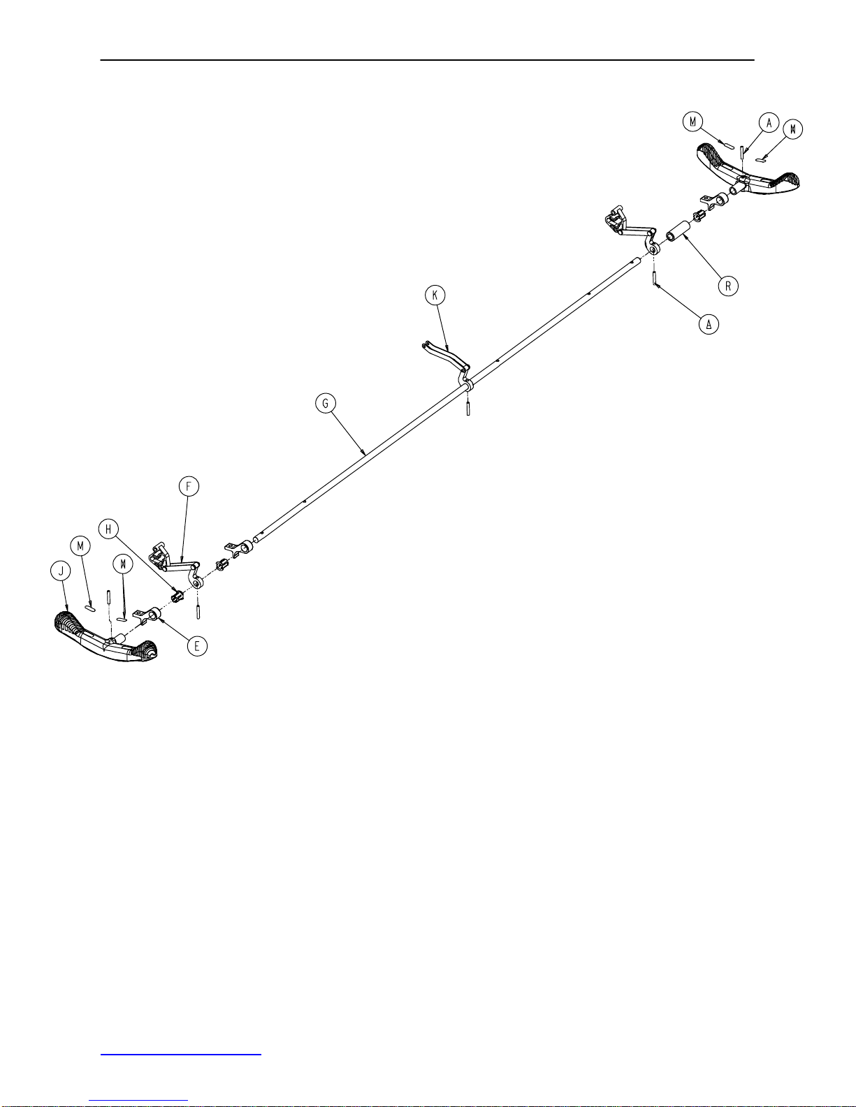
Brake Rod Assembly
Assembly part number 0753−003−001 (reference only)
Item Part No. Part Name Qty.
A 0026−067−000 Slotted Spring Pin 2
E 0753−003−004 Brake Rod Support 3
F(page 24) Drive Link Assembly 2
G 0753−003−014 Brake Rod 1
H 0753−003−015 Brake Rod Nyliner 3
J 0785−003−099 Butterfly “V” Pedal 2
K(page 25) Drive Link Assembly 1
M 1210−201−335 Red Brake Label 2
N 1210−201−336 Green Steer Label 2
R 0753−003−133 Retainment Spacer 1
Back to Table of Contents
23
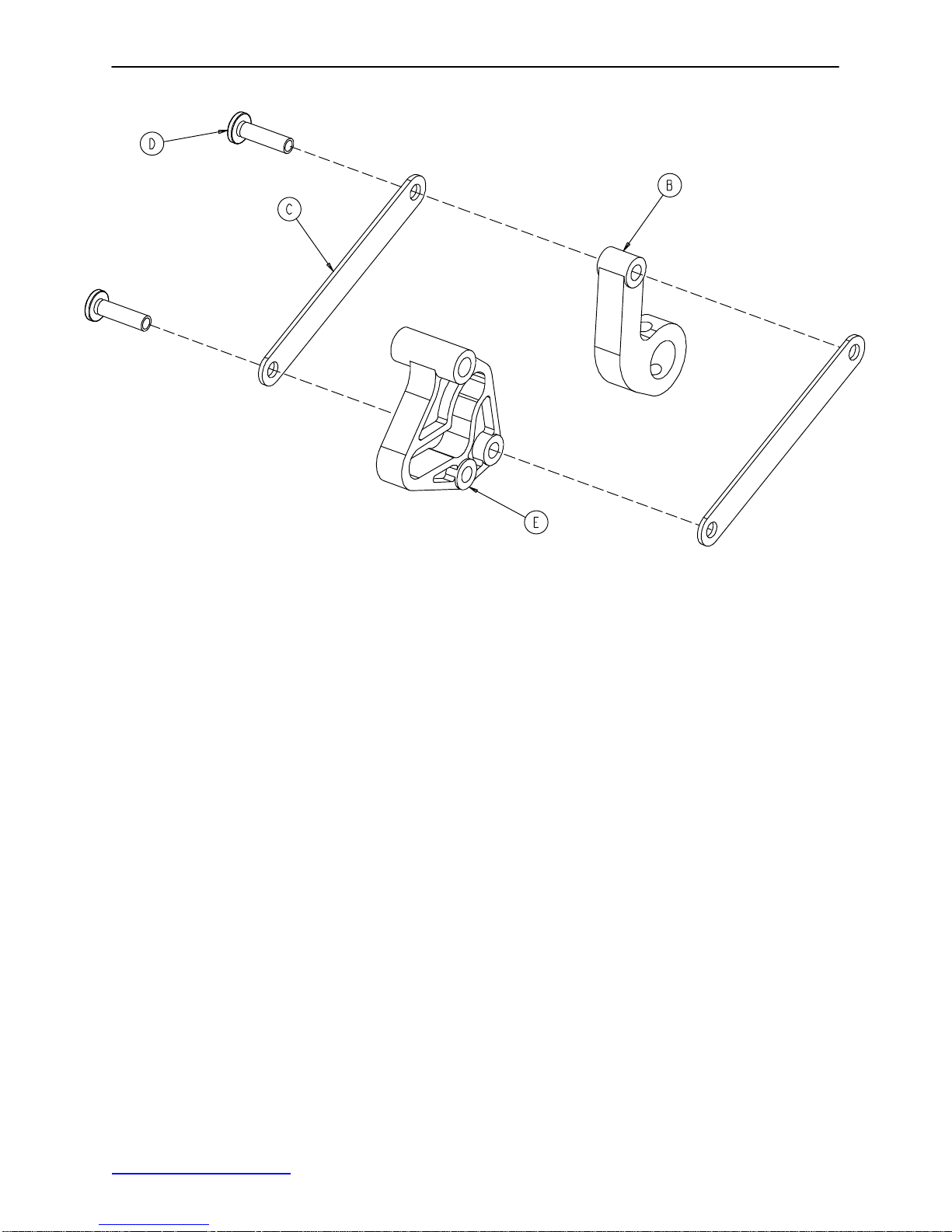
0753−006−135 Drive Link Assembly
Item Part No. Part Name Qty.
B 0753−003−011 Brake Rod Drive Link 1
C 0753−003−061 Brake Cam Drive Link 2
D 0753−003−098 Flat Hd. Semi−Tubular Rivet 2
E 0753−003−102 Brake Cam 1
Back to Table of Contents
24
 Loading...