

Page 1

3.5” Form Factor
Mirror Drive
Serial ATA MODEL
AXRE-U Series
User's Manual
P/N A203649
Revision 1.4e
Page 2

3.5" Form Factor Mirror Drive SATA Model User's Manual
This page is intentionally left blank.
Page 3
3.5" Form Factor Mirror Drive SATA Model User's Manual
Introduction
Thank you for selecting the 3.5” Form Factor SATA Mirror Drive Model. This manual describes the
proper installation procedures, operation and maintenance of your SATA Mirror Drive, and will help you
familiarize with its features.
NOTICE
Please be sure to read first the user's manual before using your SATA Mirror Drive.
This manual provides information on the appropriate handling procedures and configurations for all
product functions. This information will allow the user to take full advantage of the 3.5” Form Factor
SATA Mirror Drive Model.
In the unlikely event that you experience problems, this manual provides helpful information and
instructions.
RETAINING PACKAGING
The original packaging materials protect the SATA Mirror Drive from damage during shipment.
After unpacking the SATA Mirror Drive, please retain the packaging materials in case you need to ship
the SATA Mirror Drive in the future.
This product is sealed in an antistatic and moisture-proof bag before shipping. Open the bag only when
you are about to begin setting it up.
RECORDING THE PRODUCT NAME, VERSION, AND SERIAL NUMBERS
Before installing the SATA Mirror Drive on the host computer, please jot down the model name, version,
and serial numbers in the spaces provided for at the last page of this user’s manual. Kindly keep these
for your record purposes.
Section "
2.1 Part Names " shows the label location of model name, version, and serial number.
• THIS DOCUMENT MAY NOT BE REPRODUCED OR COPIED IN WHOLE OR IN PART.
• THE CONTENTS OF THIS DOCUMENT ARE SUBJECT TO CHANGE WITHOUT NOTICE.
• WE HAVE MADE EVERY EFFORT TO ENSURE THE ACCURACY AND COMPLETENESS OF
THIS DOCUMENT. IF YOU FIND INACCURACIES OR OMISSIONS, PLEASE CONT ACT YOUR
DISTRIBUTOR.
Copyright© Storage Vision Co., Ltd. 2007 All rights reserved.
(
To get the latest copy of this specification and to know more information about STR-V and its products,
please visit http://www.str-v.com/index_e.html)
i
Page 4
3.5" Form Factor Mirror Drive SATA Model User's Manual
To ensure the safe use of this product:
This user's manual uses the following symbols to highlight the important points related to the safe use of
this product. Please observe all safety information as indicated.
SAFETY SYMBOLS
To protect against personal injury and product damage, the following symbols are used throughout this
manual to highlight safety information.
Warning
Caution
Important
WARNING / CAUTION LABELS
Labels with black lettering against a yellow background affixed either to the exterior or interior of the
product are Warning or Caution labels that provide important safety information. Observe all the
directions given on these labels.
In cases where Warning or Caution labels can be found aside from those written in the manual, be sure
to follow the directions as mentioned.
Indicates a potentially hazardous situation that may result in
death or serious injury to the user or severe damage to the
product.
Indicates a potentially hazardous situation that may result in
serious injury to the user or damage to the product.
Indicates important information wherein failure to observe may
result to improper product function.
ii
Page 5

3.5" Form Factor Mirror Drive SATA Model User's Manual
Warning
y If you detect any abnormal conditions, such as smoke or foul odors, shut off immediately the power of
the host computer.
y If any foreign substance or material (metals, water, liquids, etc.) seeps into the SATA Mirror Drive,
shut off immediately the power of the host computer.
y Do not use the SATA Mirror Drive in hot or damp locations. Using this product in such locations may
result in fire, electrical shock, or damage.
y Do not disassemble or modify this product. STR-V cannot guarantee the performance or safety of any
product that has been repaired by the customer or by an unauthorized third party. Repairing by your
self may result in fire, electrical shock, or damage of the product.
y Before connecting or disconnecting the interface connector, turn off first the power of the host
computer and any other connected devices. To avoid placing excessive stress on the printed circuit
board of the SATA Mirror Drive, push or pull the connector only along the axis perpendicular to the
board. Avoid bending the connectors. Also avoid using undue force to connect or disconnect the
connectors or cables, which may result in fire, electrical shock, or damage.
iii
Page 6
3.5" Form Factor Mirror Drive SATA Model User's Manual
Caution
y Do not use the SATA Mirror Drive in locations subject to vibration or shock exceeding t he specified
values. Usage in such locations may result in malfunctions or disk failure.
y Do not use the SATA Mirror Drive in locations or conditions susceptible to condensation. Rapid
temperature change may cause condensation to form in the SATA Mirror Drive. If you think
condensation has occurred, allow the SATA Mirror Drive to acclimate to the new environment. When
there is a rapid temperature change, avoid using the SATA Mirror Drive until it reaches the new
ambient temperature.
y Do not place the SATA Mirror Drive near electronic components with strong electromagnetic fields,
such as televisions or loudspeakers.
Usage of the SATA Mirror Drive in such locations may result in malfunctions or disk failure.
y Turn off the power before moving the unit enclosing the SATA Mirror Drive. This will prevent
damage to the HDD and other internal components of the SATA Mirror Drive.
y Do not turn on the power immediately after turning it off, or turn off the power immediately after
turning it on. Leave at least 20 seconds in-between successive operations involving power on or off.
This will help prevent damage or malfunction to the mounted HDD. The HDD motor spindle requires
about 20 seconds to stop rotating and come to a full rest. In addition, when removing the correctly
functioning drive unit for replacement, turn off the power and wait for at least 20 seconds.
y Do not remove a fully functional drive unit while the power is still on. The SATA Mirror Drive
controller unit will consider the drive unit as failed if it is removed. Removing a fully functional drive
unit may also damage the disk heads and platter inside the HDD.
y Store the SATA Mirror Drive in the antistatic bag. Leaving this product unpacked and unused for a
long period of time may lead to malfunction or disk failure.
y Avoid applying excessive pressure to the covers of the drive unit, which may lead to malfunction or
disk failure.
y After unpacking from transport, ensure first that each disk drive is properly inserted before turning on
the power.
iv
Page 7

3.5" Form Factor Mirror Drive SATA Model User's Manual
Important
y Back up all important data stored in the SATA Mirror Drive to a suitable storage medium, such as
tape drive or MO drive. This product's mirroring technology prevents data loss even if one drive unit
fails. However, if two drive units fail at the same time or if a non-redundant part fails, data loss may
still occur. Additionally, accidental deletion of data or equipment damage may also result in data loss.
y Do not block the ventilation openings of the HDD. Lack of cooling airflow may lead to hard disk drive
failure.
y Wait at least 10 seconds after the access indicator has stopped flashing before initiating the
shutdown procedure for your host computer. The SATA Mirror Drive uses cache memory to store
the data frequently accessed from the HDD. Except in emergencies, you must follow the operating
system's shutdown procedures. Failure to so may result in loss of data stored in cache memory.
y Never remove or exchange the drive units, except to replace failed controller units or drive units,
since the SATA Mirror Drive controls the drive units by using its serial numbers. Thus, removal or
replacement may result in failure to boot up the host computer.
y When installing it in the host computer's bay, mount the SATA Mirror Drive securely using the
mounting screws provided (0.49 Nm is recommended).
y In the event of a drive unit failure, it may take up to 15 seconds to start up the SATA Mirror Drive.
The host computer may even fail to recognize it due to BIOS timeout settings.
v
Page 8

3.5" Form Factor Mirror Drive SATA Model User's Manual
Handling Static-Sensitive Device
To prevent damage to components due to static electricity, observe the following precautions when
handling this product.
y Before handling the SATA Mirror Drive or other static-sensitive devices, touch a metal object, such
as the metal enclosure of the host computer, to discharge any static electricity from your body.
y Always handle components carefully. Never touch exposed circuitry.
y When replacing controller units or drive units, or when moving the SATA Mirror Drive, place the
antistatic bag used in wrapping the product during shipment on a flat, level surface. Use this as your
SATA Mirror Drive working area.
vi
Page 9
3.5" Form Factor Mirror Drive SATA Model User's Manual
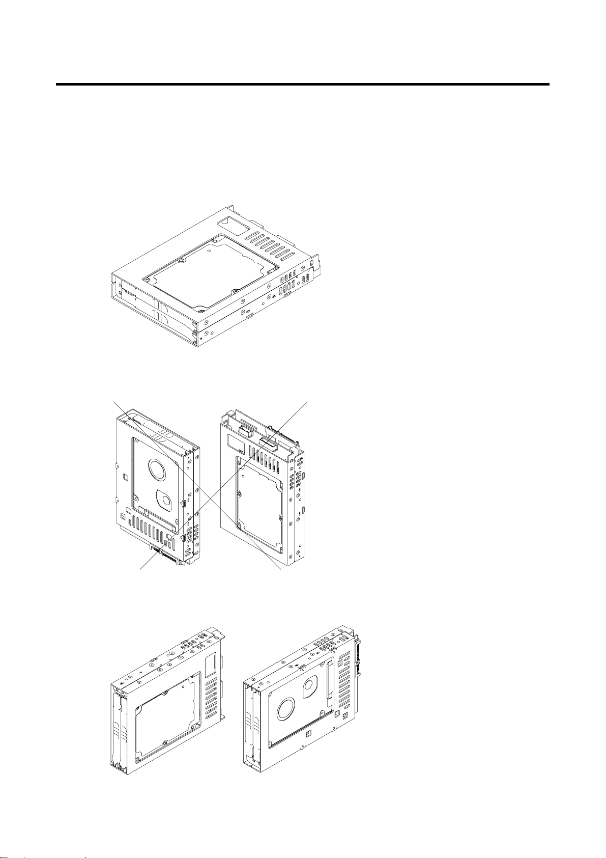
SATA Mirror Drive Installation Important Points
When installing the SATA Mirror Drive in the host computer, ensure that the drive unit is installed
horizontally, as in <A> below.
Do not install the unit vertically, i.e. with the connector facing either up or down, as in <B>.
Furthermore, when installing the unit on its side as in <C>, consult first with your distributor.
<A> Drive unit in horizontal position
<B> Drive unit in vertical position
<C> Drive unit on its side
vii
Page 10
3.5" Form Factor Mirror Drive SATA Model User's Manual
Contents
Introduction .............................................................................................................................................i
To ensure the safe use of this product:................................................................................................ii
Warning.........................................................................................................................................iii
Caution..........................................................................................................................................iv
Important.........................................................................................................................................v
Handling Static-Sensitive Device.........................................................................................................vi
SATA Mirror Drive Installation Important Points................................................................................vii
Contents...............................................................................................................................................viii
1. 3.5” Form Factor SATA Mirror Drive Functions............................................................................1
1.1 Features....................................................................................................................................1
1.2 Mirroring ...................................................................................................................................1
1.3 Cache Buffer Function.............................................................................................................2
1.4 Data Rebuilding........................................................................................................................2
1.5 Revival Reconstruction ...........................................................................................................2
2. Outline..............................................................................................................................................3
2.1 Part Names ...............................................................................................................................3
2.2 Dimensions...............................................................................................................................4
2.2.1 SATA Mirror Drive..............................................................................................................4
2.2.2 5-inch Bay Mirror Drive Installation Attachment ............................................................5
3. Installation .......................................................................................................................................6
3.1 DIP Switch Setti ngs .................................................................................................................6
3.2 Mounting in the Host Computer..............................................................................................6
3.3 Cable Connection.....................................................................................................................7
3.4 Turning on The Main Power ....................................................................................................7
4. Settings............................................................................................................................................8
4.1 DIP Switch .................................................................................................................................8
4.1.1 Operating Mode (Do not change) ....................................................................................9
4.1.2 Write Cache Mode.............................................................................................................9
4.1.3 Revival Reconstruction....................................................................................................9
4.1.4 Buzzer................................................................................................................................9
5. Status Display................................................................................................................................10
5.1 Indicator..................................................................................................................................10
5.1.1 Access Indicator .............................................................................................................10
5.1.2 Drive Status Indicator.....................................................................................................10
5.1.3 Buzzer..............................................................................................................................11
5.2 External Output Signal ..........................................................................................................12
5.2.1 Status Signal...................................................................................................................12
5.2.2 External LED Connector .................................................................................................14
5.2.3 Buzzer Stop Connector ..................................................................................................15
6. Trouble shooting...........................................................................................................................16
6.1 Trouble indication..................................................................................................................16
6.2 Replacing Drive Unit..............................................................................................................17
6.2.1 Replacement of 1 Drive Unit ..........................................................................................17
6.2.2 Replacement of Both Drive Units ..................................................................................18
6.3 Controller Unit Replacement.................................................................................................19
6.3.1 When both drive units are functioning normally..........................................................20
6.3.2 When one drive unit has failed:.....................................................................................20
6.4 Other problems ......................................................................................................................21
viii
Page 11

3.5" Form Factor Mirror Drive SATA Model User's Manual
Appendix-A Specifications..................................................................................................................22
Appendix-B Accessories .....................................................................................................................23
Appendix-C Factory Default Setting...................................................................................................24
Appendix-D Replacement Parts..........................................................................................................25
Information............................................................................................................................................26
ix
Page 12

3.5" Form Factor Mirror Drive SATA Model User's Manual
1. 3.5” Form Factor SATA Mirror Drive Functions
Incorporating two SATA 2.5-inch Hard Disk Drives, the STR-V 3.5” Form Factor SATA Mirror Drive
uses mirroring technology to safeguard data and to provide uninterrupted operations.
Since the host computer will recognize the SATA Mirror Drive as a standard SATA HDD, installing the
SATA Mirror Drive simply involves connecting it to a SATA cable from the host computer.
1.1 Features
z Supports Mirroring technology (RAID Level 1) implemented via hardware thereby reducing system
overhead.
z In the event that one of the drive unit fails, the SATA Mirror Drive will continue to function,
maintaining data integrity.
- When the failed disk is replaced with a new replacement disk, data rebuilding will begin
automatically.
- Hot plug function is supported at drive interface thereby improving system reliability.
z
Based on the industry standard Serial ATA interface, the SATA Mirror Drive can be used like any
other standard Serial AT HDD.
- No special device drivers needed.
- Compatible with most operating systems
z Compact size
- 3.5” HDD Form Factor Full Compliant
- 101.6 mm x 147 mm x 25.4 mm (W x L x H)
z Serial ATA Interface conforming to ATA/ATAPI-7 Specifications
- SATA-Ⅰwith a maximum data transfer speed of 1.5Gbps at the host interface
- Uses two 2.5-inch SATA drives that supports a maximum data transfer speed of 1.5Gbps
z Dip-switch-selectable operation mode and function
z Self-Diagnostics capability - Power On Self Test (POST) is performed every time the Mirror Drive
is turned on.
z Automatic data reconstruction every time a failed drive is replaced.
- Accepts and processes host commands even during data reconstruction.
z Cache function feature for improved system performance.
z Visual and Audible Status Indicators
- Internal buzzer for audible alarms.
- LED Indicators are provided for direct and visible status checking of each drive and the Mirror
Drive.
- External Status Bit connector is available for special customer-specific indicators.
1.2 Mirroring
Mirroring technology involves writing of data to two drive units simultaneously. If one drive unit fails, data
is written to and read from the other drive unit.
1
Page 13
3.5" Form Factor Mirror Drive SATA Model User's Manual
1.3 Cache Buffer Function
The SATA Mirror Drive is equipped with a large cache memory capacity. With write cache mode
enabled, the SATA Mirror Drive will signal completion of command processing to the host computer
when data is written to cache memory. The performance will be improved by writing accumulated data to
the HDD when the host computer is not accessing the SATA Mirror Drive. Write cache mode is enabled
thru a DIP Switch. The default setting at shipment is "enabled".
Always observe the shutdown procedure specified for the host
computer’s operating system. In delicate situations, try to wait at
least 10 seconds to be sure that both the access indicator and the
Important
drive status indicator have stopped flashing before shutting off the
power. Turning off the power while the access indicator or the
drive status indicator is still on may result in loss of data currently
located in cache memory.
1.4 Data Rebuilding
If a failed drive unit is correctly replaced, data rebuilding (the copying of all data from the fully functional
drive unit to the new replacement drive unit) will start automatically.
During data rebuilding, the drive status indicator of the fully functional drive unit will light green. The drive
status indicator of the replacement drive unit will blink orange every one second.
Caution
When a sector of the fully functional drive unit can not be read during data reconstruction, the SATA
Mirror Drive skips copying the bad sector and continues to reconstruct the remaining data. These
skipped sectors will no longer be readable. Once some data is written to this sector, it can be read
correctly again.
Important
Do not turn off the host computer while the SATA Mirror Drive is still
rebuilding the data to prevent loss of data or failure.
If the data recovery process skips some sectors during data
rebuilding, then the data on these sectors will be lost.
Periodic backup is recommended.
1.5 Revival Reconstruction
When an error occurs in a drive unit and the mirror controller cannot get the response from the drive for
30 seconds, the controller will issue the reset command to the drive and check its status again.
If the drive recovers, the SATA Mirror Drive returns to the normal operation. But if not, the controller
treats the drive as a failed drive.
The function “Revival Reconstruction” turns the power of the drive OFF/ON. And if the drive status
becomes ready, reconstruction is started.
Revival reconstruction is executed up to two times. After the same error occurs three times, the SATA
Mirror Drive will remain in Degraded Mode. Then the failed drive status indicator (LED) will light orange.
The function can be enabled /disabled by Dip Switch. Factory default is “enabled”.
The SATA Mirror Drive still responds to the host normally even during reconstruction. After the
reconstruction is finished, the SATA Mirror Drive returns to normal mode automatically.
2
Page 14
2. Outline
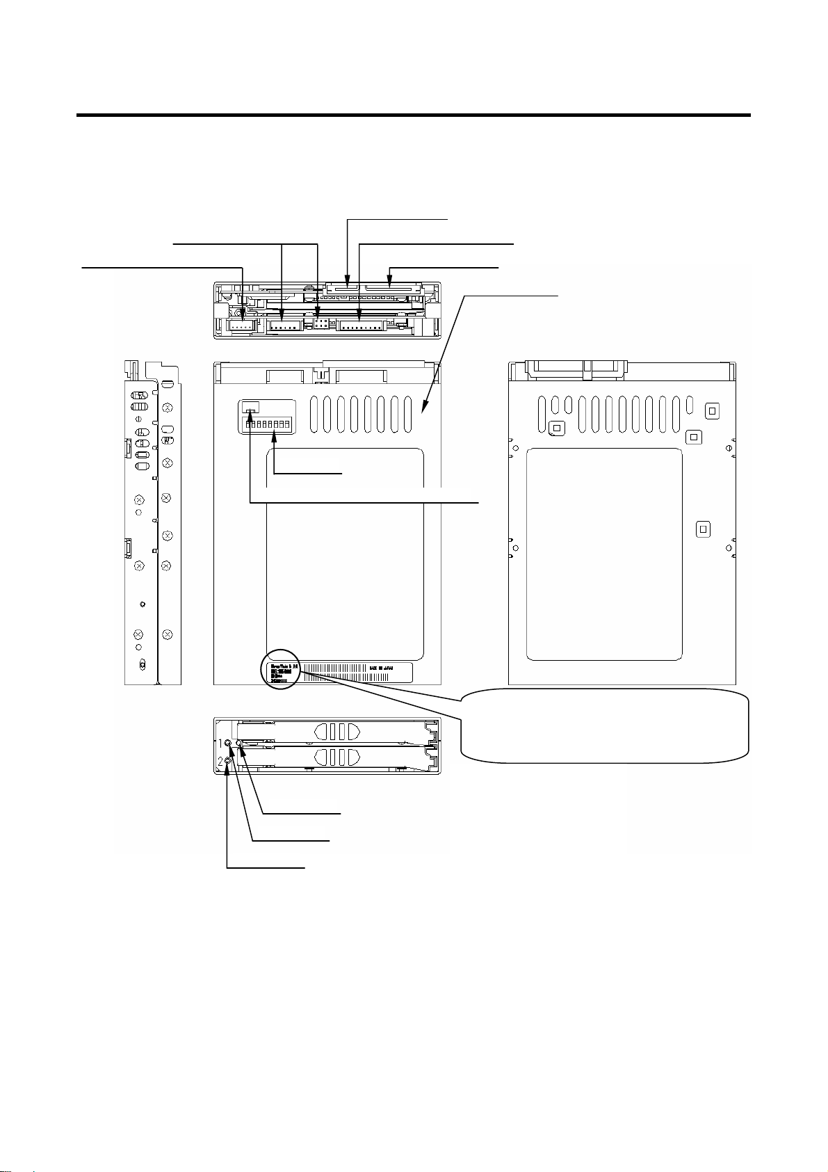
2.1 Part Names
Buzzer Stop Signal Connector
3.5" Form Factor Mirror Drive SATA Model User's Manual
SATA Connector
External LED ConnectorStatus Signal connector
Power Connector
Controller Unit
Dip Switch
Status Signal Voltage Selection Switch
Access LED
Drive 1 LED
Drive 2 LED
MODEL: AXRE-U
****
*********
← Verion
← Serial Number
EC: YB
S/N:
← Mode l Name
***SA*
3
Page 15
3.5" Form Factor Mirror Drive SATA Model User's Manual
61.0
60.0
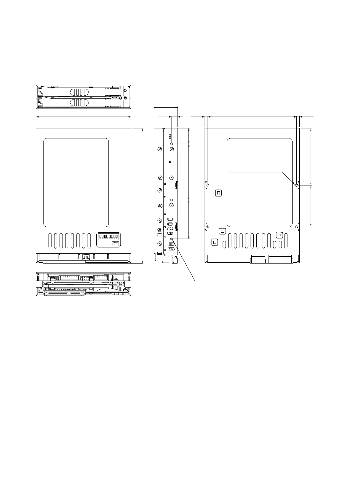
2.2 Dimensions
2.2.1 SATA Mirror Drive
101.6
25.4
6.4 3.2 95.2
Mounting Screw Holes
取付け用ネジ穴(4ヶ所)
ユニファイ並目ネジ
Unit:mm
3.2
6144.5
4-#6-32UNC
144.5
41.6 60 16.9
取付け用ネジ穴(3ヶ所)
Mounting Screw Holes
3-#6-32UNC
ユニファイ並目ネジ
対面も同等
4
Page 16
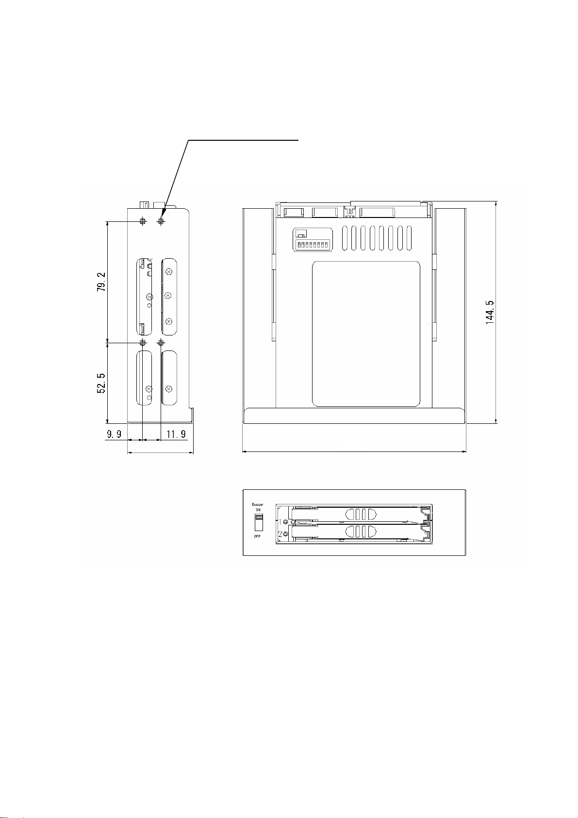
3.5" Form Factor Mirror Drive SATA Model User's Manual
2.2.2 5-inch Bay Mirror Drive Installation Attachment
Mounting Screw Holes
取付け用ネジ穴(4 ヶ所)
4-#6-32UNC
ユニファイ並目ネジ
対面も同等
Unit:mm
43.0
146.0
5
Page 17
3.5" Form Factor Mirror Drive SATA Model User's Manual
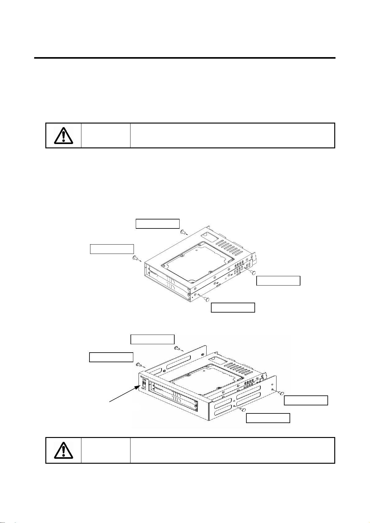
3. Installation
3.1 DIP Switch Settings
Before mounting the SATA Mirror Drive in your host computer, double-check the DIP Switch settings.
Refer to "4. Settings" for the configurations of the DIP switch. For default settings, refer to "
Factory Default Settings
."
Appendix-C
Caution
When setting the switches and attaching the cables, ensure first that
the power supply of the host computer is turned off.
3.2 Mounting in the Host Computer
When mounting in the host computer, use the attached mounting screws and the specified mounting
holes. The mounting screw hole locations are shown in "
An example of a mounting screw hole location is shown below.
Mounting Screw
Mounting Screw
Refer to「4.1.4 BUZZER」
Caution
Mounting Screw
Mounting Screw
When installing into the host computer, provide sufficient cooling in
order to ensure that the surface temperature of the drive unit remains
below 50°C.
2.2 Dimensions."
Mounting Screw
Mounting Screw
Mounting Screw
Mounting Screw
6
Page 18
3.5" Form Factor Mirror Drive SATA Model User's Manual
3.3 Cable Connection
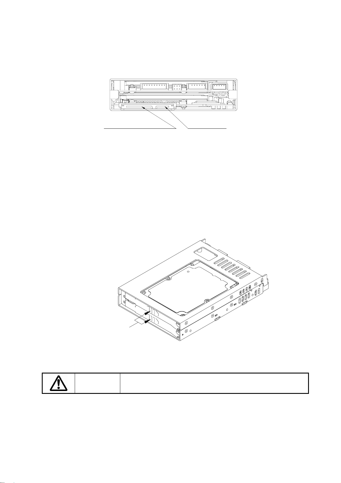
<1> Connect SATA power cable that supplies DC +5V.
<2> Use a standard SATA signal cable to connect to the host computer.
SATA Connector
Serial ATA コネクタ
Power Connector
電源コネクタ
3.4 Turning on The Main Power
Before turning on the host computer, gently press the front face of each drive unit to confirm that these
are firmly inserted and verify if the lever lock is firmly fixed.
Next, turn on the host computer’s main power supply and check if the host computer detects the unit
correctly.
Push the drive units
and verify if the units
are firmly inserted.
Caution
Before turning on the host computer, make sure that both the Signal
and power cables are attached properly.
7
Page 19
3.5" Form Factor Mirror Drive SATA Model User's Manual
4. Settings
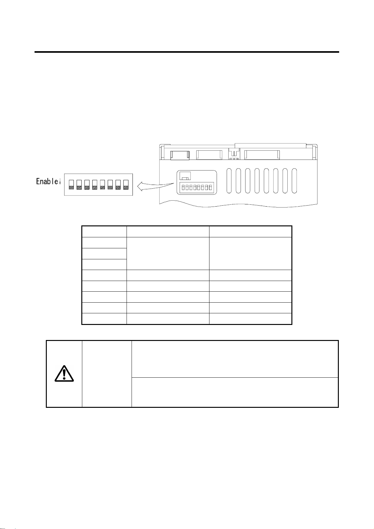
4.1 DIP Switch
The DIP Switch can be used to change the settings of Write Cache mode, DMA setting Revival
Reconstruction Feature and Buzzer Enable/Disable Features of the SATA Mirror Drive.
It is located on the upper right side of the sub-card (at the back of CN13).
Since the SATA Mirror Drive is a high-speed and reliable storage unit, its default DIP Switch settings
are set to maximize its performance.
ON
12345678
DIP Switch Functions Default Switch position
S1
S2
S3
S4 Reserved OFF
S5 Write Cache
S6 Revival Reconstruction
S7 Buzzer
S8 Reserved OFF
Caution
Mode Bit 1,2,3
(Normal Mode)
Except for S6 & S7, turn off the power of the host computer before
changing the setting of the switches.
(The above diagram shows the default factory settings before
shipping.)
Do not change the Mode Bit switches (S1、S2、S3、S4) and S8.
Otherwise, performance and function variations may occur in the
unit.
OFF(Normal)
OFF(Enabled)
OFF(Enabled)
OFF(Enabled)
8
Page 20
3.5" Form Factor Mirror Drive SATA Model User's Manual
4.1.1 Operating Mode (Do not change)
The operating mode switches (S1、S2、S3、S4 & S8) are set to normal mode (mirror mode). Do not
change this setting.
Important
Changing the operation mode switches will result in loss of data.
4.1.2 Write Cache Mode
This bit sets the write cache mode. If set to "OFF" (Default Setting meaning Write Cache Enabled), the
SATA Mirror Drive will signal completion of command processing to the host computer when the data
has been written to cache memory. If set to “ON”, the SATA Mirror Drive will signal completion of
command processing to the host computer when data is actually written to the drive unit.
Always observe the shutdown procedure specified for the host
computer’s operating system. In delicate situations, try to wait at
least 10 seconds to be sure that both the access indicator and the
Important
drive status indicator have stopped flashing before shutting off the
power. Turning off the power while the access indicator or the drive
status indicator remains lit may result in loss of data currently located
in cache memory.
4.1.3 Revival Reconstruction
If the bit is set to "OFF" (Default Setting meaning Revival Reconstruction Enabled), the SATA Mirror
Drive will attempt to do data reconstruction after Error Recovery Procedure fails while in Retry Mode.
The SATA Mirror Drive will not remain in Degraded Mode but instead, will automatically do data
reconstruction to trying to revive the drive up to two times.
4.1.4 Buzzer
If the bit is set to "OFF" (Default Setting meaning Buzzer Enabled), the buzzer will sound when any error
is detected. In the event of a drive unit failure, the buzzer will continue to sound until the failed drive unit
is replaced. The buzzer can be stopped if the switch position is changed to “ON”.
Set back the buzzer to "OFF" after the failed drive unit has been replaced.
When an external bracket is used for the 5" Drive Bay installation, please make sure that Bit 7 setting of
the Dip Switch is set to Enable. The buzzer sound can be turned ON and OFF through the Buzzer switch
in the external bracket. If the buzzer is turned OFF prior to drive replacement, slide it back to ON after
the new drive unit has been inserted.
9
Page 21
3.5" Form Factor Mirror Drive SATA Model User's Manual
5. St atus Display
5.1 Indicator
LED indicators on the front display the status of both controller unit and drive units.
5.1.1 Access Indicator
(*1)
ACCESS
Green
Orange
Flashing
<1> When the power is turned on.
<2> Processing a command from the host computer.
Either of the above.
<1> Both drive units have failed, both drive units are not correctly inserted.
(Both drive status indicators are off.)
<2> When one drive unit has failed and the fully functional drive unit has been
erroneously replaced.
(Both drive status indicators show green simultaneously.)
<3> Both drive units have been replaced.
(Both drive status indicators show green simultaneously.)
Any of the above.
5.1.2 Drive Status Indicator
<1> When the power is turned on.
Green
<2> Processing a command from the host computer.
<3> Processing an internal command.
Either of the above.
DRIVE1
DRIVE2
Orange
<1> When the power is turned on.
<2> Drive unit has failed.
Either of the above.
Orange Target drive unit of data rebuilding.
Flashing
(Source drive unit LED is green at the same time.)
Note:
(*1)
When turning the power on, the access indicator shows green, and both drive status indicators
show orange then green. When SATA Mirror Drive startup process is complete, all will be turned
off.
(*2)
Drive Status Indicator will go out after data rebuilding.
If the drive status indicator flashes orange, immediately replace the
Important
said drive unit. Leaving the SATA Mirror Drive with a failed drive
unit will result in data loss if the other drive unit fails.
(*1)
(*1)
(*2)
10
Page 22
3.5" Form Factor Mirror Drive SATA Model User's Manual
5.1.3 Buzzer
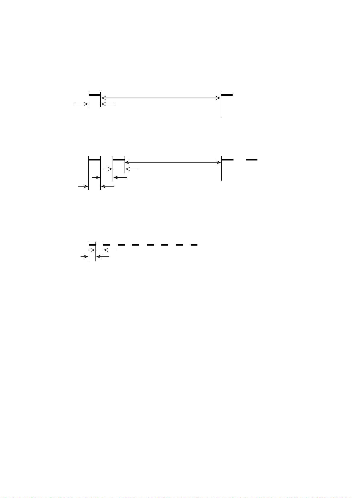
If this is set to "ENABLE," in the event of a failure, the buzzer will beep at the interval specified below.
Drive unit 1 failed
Buzzer
Drive unit 2 failed
Buzzer
System stopped (Both drive units have failed)
Buzzer
Beep Beep
3.2s
0.3s
Beep Beep
3.1s
0.3s
0.3s
0.3s
Beep
Beep Beep Beep Beep Beep Beep Beep
0.1s
0.1s
Beep Beep
11
Page 23
3.5" Form Factor Mirror Drive SATA Model User's Manual
r
5.2 External Output Signal
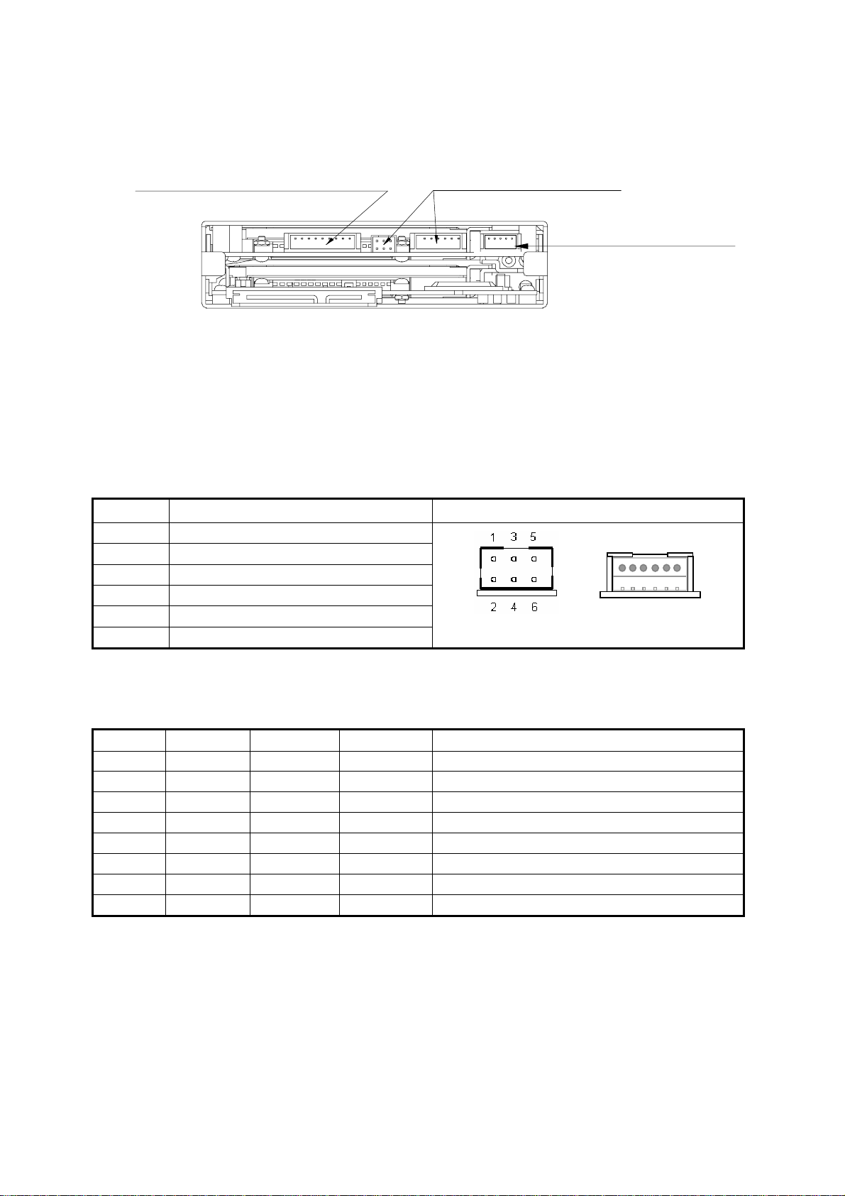
It is possible to monitor the SATA Mirror Drive status externally. The locations of the connector are
shown in the figure below.
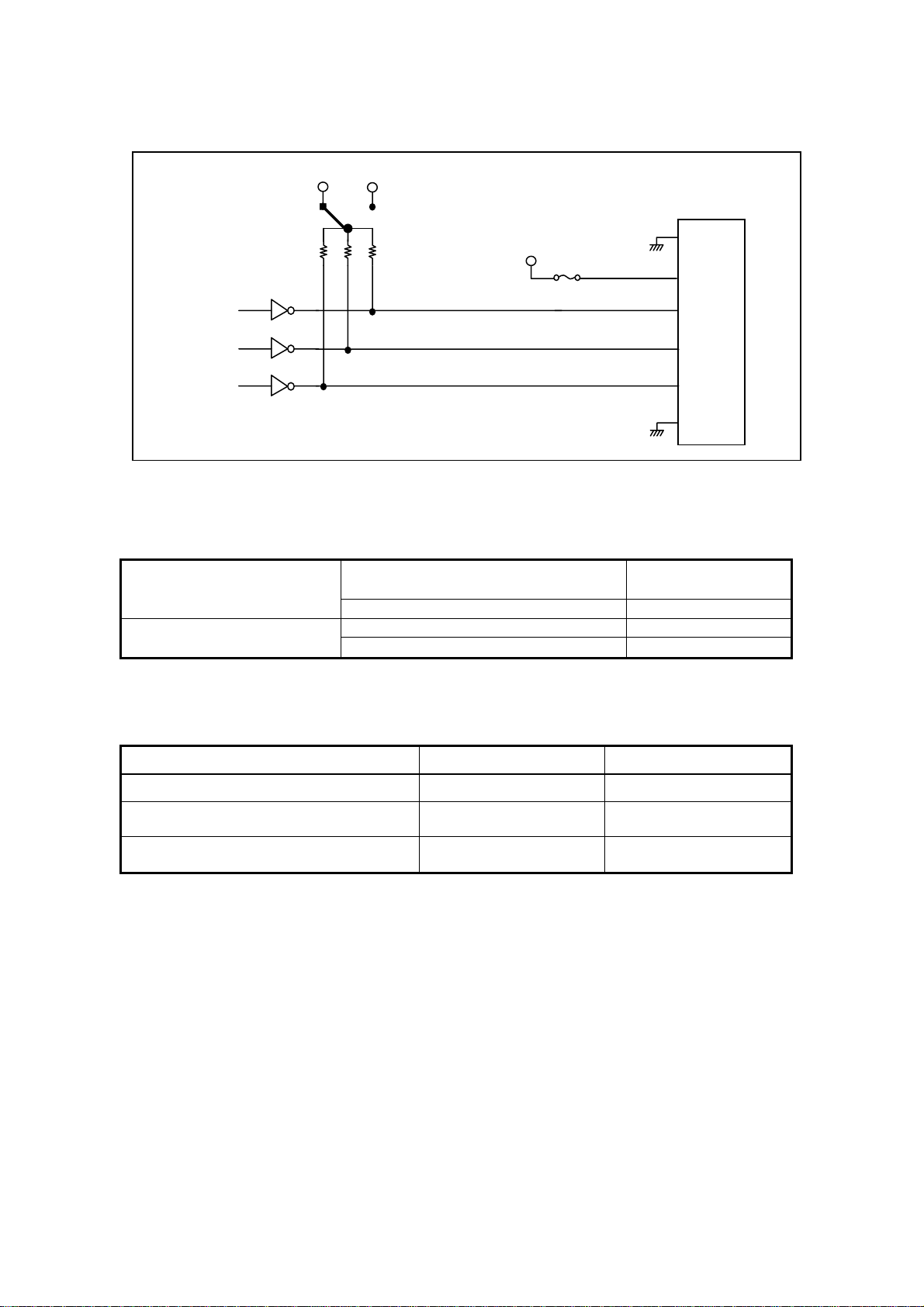
5.2.1 Status Signal
External status output is transmitted as a 3-bit signal through the Status Bit connector.
This table shows the pin configurations, status definitions, internal circuitry, electrical specifications, and
connector specifications for the status output signal.
● The connector signal pins are configured as follows:
External LED Connecto
外部LEDステ-タス信号コネクタ
Status Signal
ステ-タス信号コネクタ
Buzzer Stop Connector
1 GND
2 +3.3VDC (Default) / +5V
Signal Connector Pin Assignment
1 6 2 3 4 5
(Option)
DC
3 Status Bit 2
4 Status Bit 1
5 Status Bit 0
6 GND
CN2
CN13
● Status output is transmitted in 3-bit signals, as follows:
Bit 2 Bit 1 Bit 0 Status
0 L L L Normal Operation
1 L L H Drive Unit 1 Failed
2 L H L Drive Unit 2 Failed
3 L H H Data rebuilding
4 H L L Controller unit failure
(*1)
5 H L H Reserved
6 H H L SATA Mirror Drive startup processing
7 H H H Initializing
H: TTL level output high.
L: TTL level output low.
Note:
(*1)
The following condition will cause a Controller unit failure transmit status.
- If both drive units fail when the power is turned on.
- If both drive units are not properly connected when the power is turned on.
- If the correctly functioning drive unit is erroneously replaced when one of the drive units failed.
12
Page 24
3.5" Form Factor Mirror Drive SATA Model User's Manual
g
The internal circuitry of status output signals are indicated as follows:
●
3.3V
5V
Status Si
Bit 2
nal
S3
Default:
+3.3V
10kΩ
5V
Fuse: 500mA
Bit 1
Bit 0
74LS06
● Status Output Signal electrical specification
CN13/CN23
Pin 1
Pin 2
Pin 3
Pin 4
Pin 5
Pin 6
Voltage
(Selectable Through S3)
Current
● Connector specifications
SATA Mirror Drive header
External Connector Crimp Socket –
(recommended)
External Connector Crimping Contact –
(recommended)
Note: All components are from HIROSE Electric Co. Ltd.
+5.0V
(Default) /
(Option)
max)
Output High Voltage
Output Low Voltage (V max) +0.4V
(V
DC
DC
+3.3V
Output Sink (Low) Current (max) 20mA
Output Source (High) Current
(max) 0.25mA
CN13 CN23
DF3Z-6P-2H (50) DF11-6DP-2DS (24)
DF3-6S-2C DF11-6DS-2C
DF3-248SCC DF11-2428SC
13
Page 25
3.5" Form Factor Mirror Drive SATA Model User's Manual
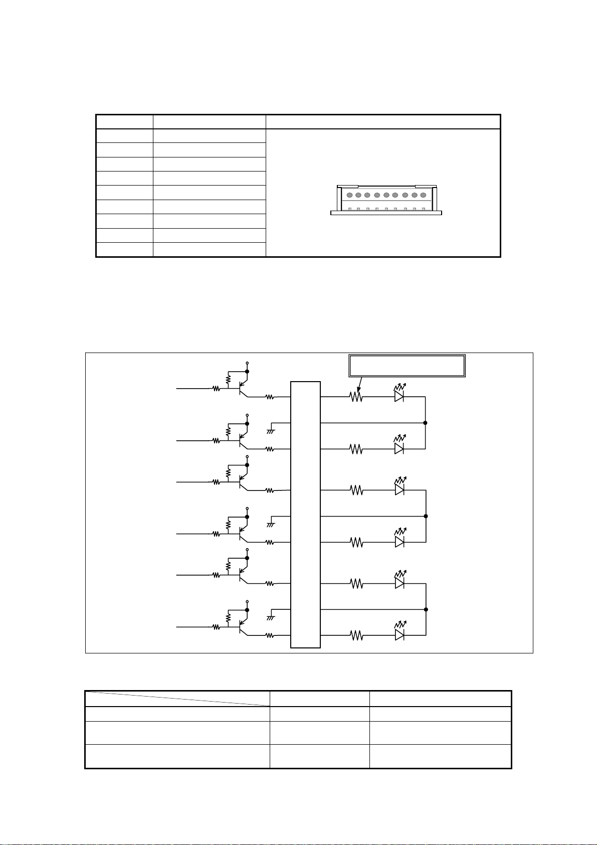
5.2.2 External LED Connector
It is possible to drive external LED by CN14. Please refer to
Pin No. Status Connector Pin Assignment
1 ACCESS LED Green
2 GND
3 ACCESS LED Orange
4 DRIVE 1 Green
5 GND
6 DRIVE 1 Orange
7 DRIVE 2 Green
8 GND
9 DRIVE 2 Orange
● External LED Driver and recomended circuits.
The external LEDs indicate the same status as the LEDs on the front of the SATA Mirror Drive.
External LEDs can be connected as shown below. The brightness can be adjusted by any resister
from 0 ohm to 150 ohm.
“ 2.1 Part Name’s ” for it’s location.
CN14
1
9
Note : AXRD-UxxxAx Compatible
Mirror Card
LED Control signal
LED Control signal
LED Control signal
LED Control signal
LED Control signal
LED Control signal
● CN14 Connector
Part Name Maker
Mirror Drive Header
External Connector Crimp Socket –
(recommended)
External Connector Crimping Contact –
(recommended)
3.3V
3.3V
3.3V
3.3V
3.3V
3.3V
Adjust from 0 to 150Ω
ACCESS LED Green
82Ω
Pin 1
Pin 2
82Ω
82Ω
Pin 3
Pin 4
ACCESS LED Orange
DRIVE 1 Green
Pin 5
82Ω
Pin 6
DRIVE 1 Orange
DRIVE 2 Green
Pin 7
82Ω
Pin 8
DRIVE 2 Orange
82Ω
Pin 9
DF3Z-9P-2H (50) HIROSE Electric Co.,LTD
DF3-9S-2C HIROSE Electric Co.,LTD
DF3-2428SCC HIROSE Electric Co.,LTD
14
Page 26
3.5" Form Factor Mirror Drive SATA Model User's Manual
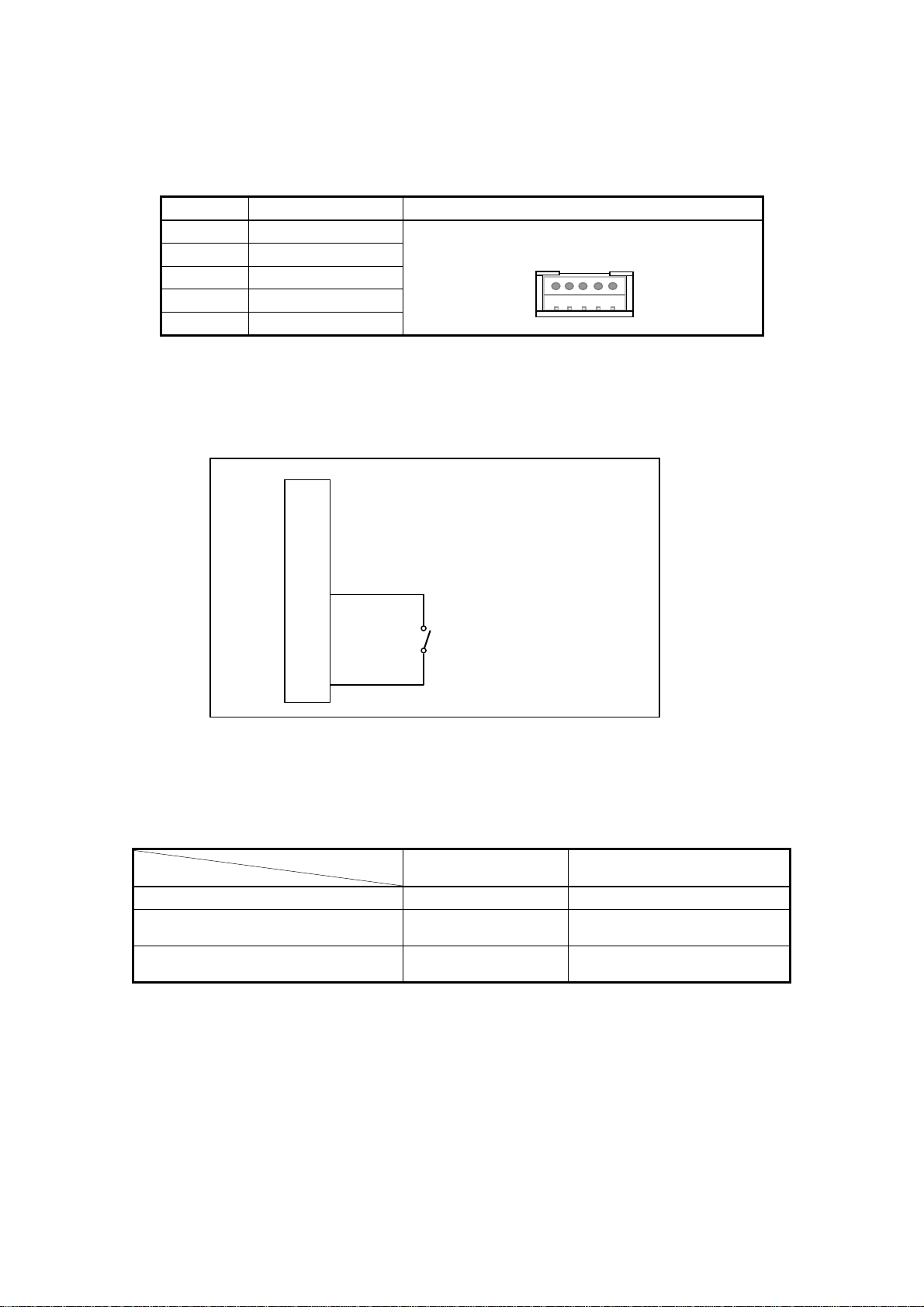
5.2.3 Buzzer Stop Connector
The buzzer can be stopped by a switch connected to the pin no. 3 and 5 of CN6. Please refer to
Name’s ”
※:The Pins reserved must be open.
● Recomended circuits to stop buzzer
● CN6 Connector
for it’s location.
Pin No. Functions Connector Pin Position
1
2
3 5V
4 GND
5 Buzzer Stop
Reserved ※
Reserved ※
CN6
1
Pin 1
Pin 2
Pin 3
Pin 4
Short:Buzzer Stop
Open:Buzzer On
Pin 5
5
“ 2.1Part
Part Name Maker
Mirror Drive Header
External Connector Crimp Socket –
(recommended)
External Connector Crimping
Contact – (recommended)
DF3-5P-2DS (01) HIROSE ELECTRIC Co.,LTD
DF3-5S-2C (01) HIROSE ELECTRIC Co.,LTD
DF3-2428SCC HIROSE ELECTRIC Co.,LTD
15
Page 27
3.5" Form Factor Mirror Drive SATA Model User's Manual
6. T rouble shooting
6.1 Trouble indication
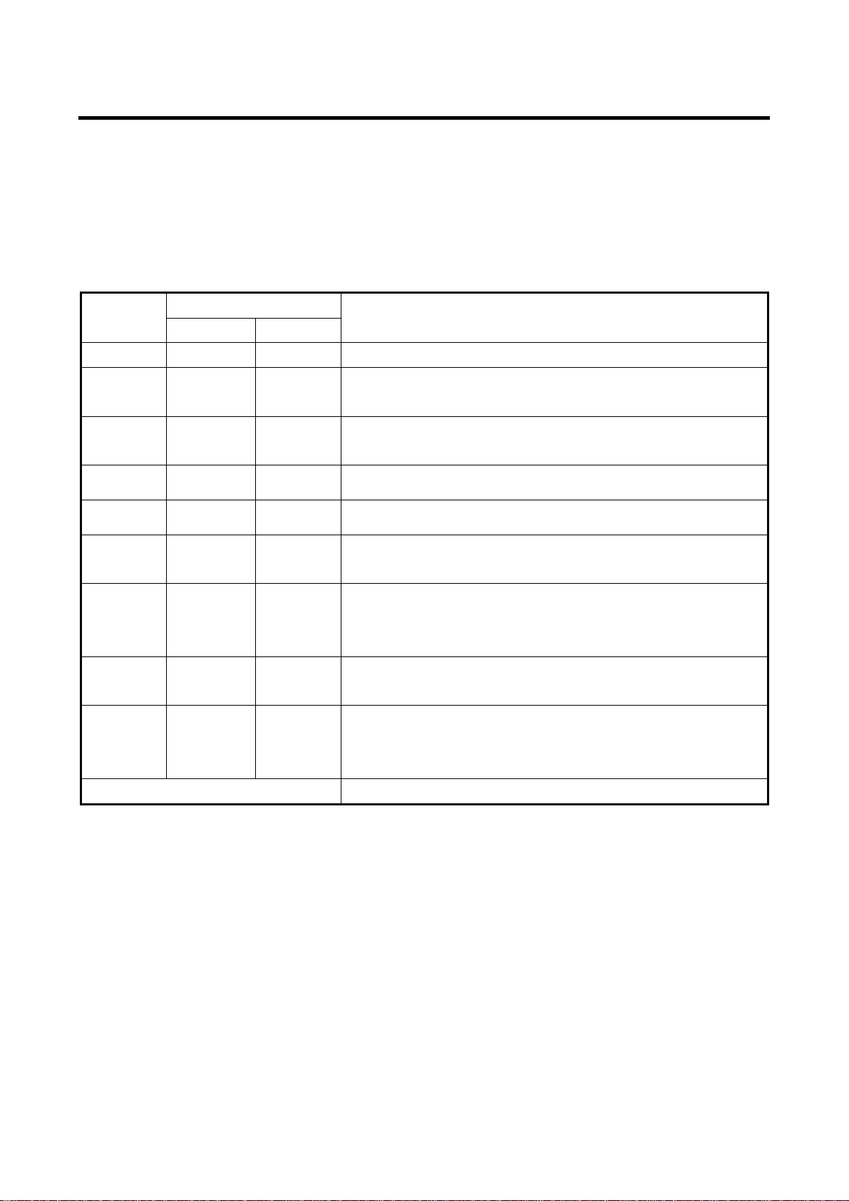
If the SATA Mirror Drive fails, either the access indicator LED or the drive status indicator LED will flash
Orange.
If the buzzer switch is enabled, the buzzer will emit a continuous beeping sound.
These status/failure indications must be considered to determine if removal and replacement of a hard
disk unit is necessary.
Access
indicator
--- --- --- Normal operation.
Drive status indicator
Drive unit 1 Drive unit 2
SATA Mirror Drive status and measures.
--- Green
---
--- Orange ---
--- --- Orange
Orange --- ---
OFF OFF OFF
Orange
flashing
Orange
flashing
Other LED indications not mentioned. Contact your distributor.
---:Normally off but will light up or flash when accessed.
If replacing the drive unit does not fix the problem, contact your distributor.
Orange
flashing
OFF OFF
Green Green
Orange
flashing
Green
Rebuilding data from drive unit 1 to drive unit 2.
(Normal operation)
Rebuilding data from drive unit 2 to drive unit 1.
(Normal operation)
Drive unit 1 failure. Replace the drive unit 1 with a new drive
unit.
Drive unit 2 failure. Replace the drive unit 2 with a new drive
unit.
Controller unit failure. Replace the controller unit with a new
controller unit.
When the SATA Mirror Drive does not respond to the host,
check the condition of the power supply.
If problem persists, please contact your distributor.
Check the condition of both drive units.
If problem persists, please contact your distributor.
Double-check to confirm that the desired drive unit was properly
replaced. Temporarily return to the original setup and repeat
the process.
16
Page 28
3.5" Form Factor Mirror Drive SATA Model User's Manual
6.2 Replacing Drive Unit
A failed drive unit can be replaced while the SATA Mirror Drive is accessed.
When the failed drive unit is replaced with a new drive unit, data rebuilding will begin automatically.
During data rebuilding, the host computer can still access the SATA Mirror Drive.
Note: Make sure that the drive status indicator (LED) lights orange before replacing a failed unit.
Before replacing the failed drive unit, be sure to prepare the
replacement drive unit designated by STR-V as described in
"Appendix-D Replacement Parts. " Do not replace with HDDs other
than the designated model, even if the capacity, manufacturer, or
Important
Important
model numbers on the label are the same. Using an unauthorized
HDD may result in malfunction or damage. The warranty does not
cover any damage encountered due to replacement with a
non-specified HDD. Furthermore, STR-V is not held liable for any
consequence resulting from the use of an undesignated HDD.
If the drive status indicator lights orange, immediately replace the
specified drive unit with a new drive unit. Leaving the SATA Mirror
Drive with a single operational drive unit for an extended period will
result in data loss if the other drive unit fails.
Before handling the drive unit when replacing a failed drive, touch a
Caution
metal object first, such as the metal enclosure of the host computer,
to discharge static electricity from your body.
6.2.1 Replacement of 1 Drive Unit
● Drive Unit Replacement Procedure.
1. Prepare a new drive unit as specified in "
2. Confirm correct identification of the failed drive unit through the drive status indicator or buzzer.
If the failed drive unit can not be removed during power ON
3.
computer and remove the SATA Mirror Drive.
4. Slide the front lever to the left and release the lever.
5. Pull the failed drive unit's lever, and then pull out the drive unit.
6. Push the replacement drive firmly into the unit with both hands.
7. Slide to the front lever to the right and close the lever.
8. Confirm that the front lever is fixed.
If the SATA Mirror Drive was removed
9.
confirm that the host computer recognize the SATA Mirror Drive.
Appendix-D Replacement Parts."
, turn off the power supply of the host
, set it back into the host computer, turn on the power and
17
Page 29
3.5" Form Factor Mirror Drive SATA Model User's Manual
10. Several seconds after replacing the drive unit, data rebuilding will start. The drive status indicator
of the replaced drive unit will flash orange (@ 1 second interval).
Important
11. During data rebuilding, the drive status indicator of the replacement drive will flash orange, and
the drive status indicator of the fully functional drive unit will light green. The access indicator will
not light.
12. When data rebuilding is complete, the drive status indicator will go out.
Important
Do not remove the drive unit while data rebuilding is underway.
If you have mistakenly replaced the correctly functioning drive unit,
the drive status indicator of both drive units will light green. Then the
access indicator will flash orange. The host computer will be unable
to operate the SATA Mirror Drive.
In this case, turn off the host computer. Replace the failed drive unit
with the new drive unit, and return the fully functional drive unit. Data
rebuilding will immediately start after turning on the host computer.
6.2.2 Replacement of Both Drive Units
When both drive units seem to have failed, replace the units according to the following procedure.
This is an emergency recovery procedure; data corruption may or
may have already occurred.
Important
1. Prepare the two new drive units as specified in "
2. Turn off the power supply of the host computer.
3. The drive unit to be replaced first should be the one that failed first.
Slide to the left the grooved mark on the front lever and open the lever.
4. Hold the lever of the drive unit that failed first and then pull it out.
5. Turn on the power supply of the host computer.
6. Confirm that the host computer recognizes the SATA Mirror Drive.
7. After confirming that the host computer recognizes the SATA Mirror Drive, insert the
replacement drive. Push firmly the replacement drive right into the unit with both hands then with
the use of the grooved marking, carefully slide the lever to the right.
8. Several seconds after replacing the drive unit, data rebuilding will start. The drive status indicator
of the replacement drive unit will flash orange (@1 second interval).
To avoid further data loss, back up your data in a suitable medium,
such as tape or MO drive.
Please use an STR-V designated HDD as drive replacement. Refer
to “Appendix-D Replacement Parts” for more details.
Appendix-D Replacement Parts."
18
Page 30
3.5" Form Factor Mirror Drive SATA Model User's Manual
Important
9. During data rebuilding, the drive status indicator of the replacement drive will flash orange, while
the drive status indicator of the other drive unit will light green. The access indicator will not light.
10. When data rebuilding is complete, the drive status indicator will go out.
After confirming that the drive status indicator has gone out, turn off the power supply of the host
computer.
11. Slide to the left the grooved mark of the lever of the un-replaced drive unit and open the lever.
Hold the lever of the driver unit,then pull it out.
12. Push firmly the replacement drive right into the unit with both hands then with the use of the
grooved marking, carefully slide the lever to the right.
13. Confirm that the front lever is locked.
14. Turn on the power supply of the host computer.
15. Several seconds after replacing the drive unit, data rebuilding will start. The drive status indicator
of the replacement drive unit will flash orange (@1 second interval).
Do not remove the drive unit while data rebuilding is underway.
Important
16. During data rebuilding, the drive status indicator of the replacement drive will flash orange, while
the drive status indicator of the fully functional drive unit will light green. The access indicator will
not light.
17. When data rebuilding is complete, the drive status indicator will go out.
Do not remove the drive unit while data rebuilding is underway.
6.3 Controller Unit Replacement
If the access indicator or the drive status indicator lights orange even after drive replacement, the
controller may have a problem. In this case, replace the controller unit.
When replacing the controller unit, data can be kept safe by following the correct replacement
procedure.
Note that the replacement procedure will differ depending on the drive units’ status.
<1> If both drive units are functioning normally:
Switch over both drive units to a new controller unit.
Ensure that each drive unit is inserted into exactly the same drive bays as before.
<2> If one drive unit has failed:
When it has been confirmed that one drive unit has failed, ensure that only the correctly functioning
drive unit is inserted into the same bay of the new controller.
19
Page 31
3.5" Form Factor Mirror Drive SATA Model User's Manual
When replacing controller units, make sure to turn off the power of the
host computer, and the AC power cable is removed from the socket.
Caution
When replacing drive units, ensure that you touch the chassis or any
other grounded parts, to discharge static electricity from your body.
Do not subject the drive units or the controller to vibration or shock.
It may result in malfunction or disk failure.
6.3.1 When both drive units are functioning normally
● Controller Unit Replacement Procedure.
1. Prepare a new controller unit as specified in " Appendix-D Replacement Parts."
2. Turn off the power supply of the host computer.
3. Disconnect the SATA Signal cable and the power cable. Then remove the SATA Mirror Drive
from the host computer.
4. Slide to the left the grooved mark on the front lever and open the lever.
5. Release both drive units’ lever one after the other and then pull it out.
6. Insert the drive units into the new controller unit. Make sure drive unit numbers 1 and 2 are kept
as they were before replacement. One after the other, push firmly the drives right into the unit with
both hands then with the use of the grooved marking, carefully slide the lever to the right.
7. Confirm that both front levers are fixed.
8. Re-install the SATA Mirror Drive back into the host computer, re-connect the SATA Signal cable
and then finally, the power cable.
9. Turn on the power supply of the host computer.
6.3.2 When one drive unit has failed:
● Controller Unit Replacement Procedure.
1. Prepare a new drive unit and a new controller unit as specified in "
."
Parts
2. Confirm which drive unit has failed through the drive status indicator or buzzer.
3. Turn off the power supply of the host computer.
4. Disconnect the SATA Signal cable and the po wer cable. Then remove the SATA Mirror Drive
from the host computer.
Slide to the left the grooved mark on the front lever of the good drive and open the lever.
5.
6. Pull out the good drive unit first.
20
Appendix-D Replacement
Page 32
3.5" Form Factor Mirror Drive SATA Model User's Manual
7. Insert the good drive unit into the new controller unit.
Please keep the location of the drive unit (number 1 or 2) as it was before.
Push firmly the drive right into the unit with both hands then with the use of the grooved marking,
carefully slide the lever to the right.
8. Confirm that the front lever is fixed.
9. Install the SATA Mirror Drive into the host computer, re-connect the SATA Signal cable and then
finally, the power cable.
10. Turn on the power supply of the host computer.
11. Confirm that the host computer recognizes the SATA Mirror Drive.
12. Insert the new drive unit into the other empty slot.
Push firmly the replacement drive right into the unit with both hands then with the use of the
grooved marking, carefully slide the lever to the right.
13. Confirm that the front levers are fixed.
14. Several seconds after replacing the drive unit, data rebuilding will start. The drive status indicator
of the replacement drive unit will flash orange (@1 second interval).
Important
15. During data rebuilding, the drive status indicator of the replaced drive will flash orange, while the
drive status indicator of the fully functional drive unit will light green. The access indicator will not
light.
16. When data rebuilding is complete, the drive status indicator will go out.
Do not remove the drive unit while data rebuilding is underway.
6.4 Other problems
If the problem persists even after you have replaced the drive unit or the controller unit, please contact
your distributor.
In addition, if you also happen to encounter other types of problems not mentioned in this manual,
please contact your distributor immediately.
21
Page 33
3.5" Form Factor Mirror Drive SATA Model User's Manual
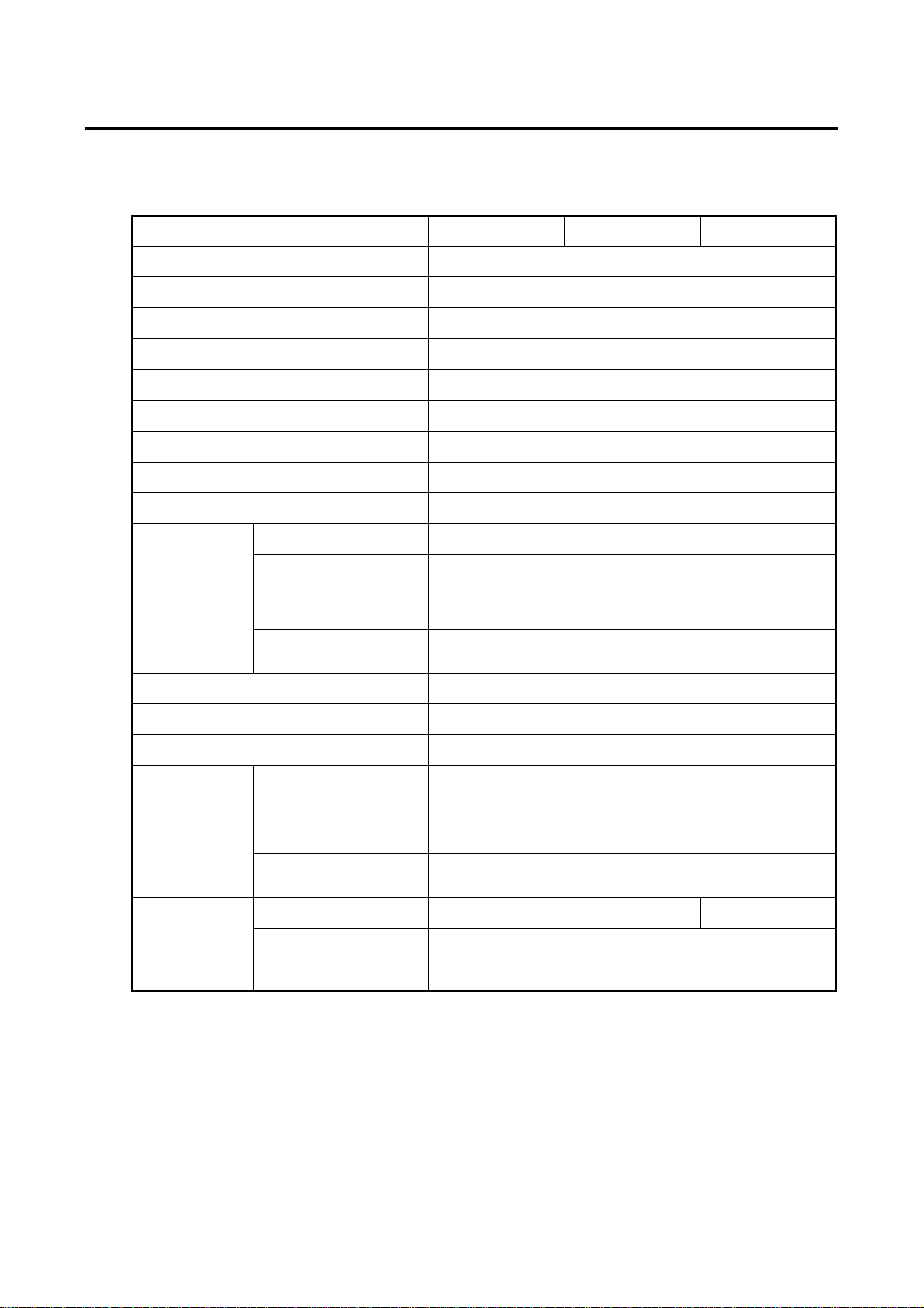
Appendix-A Specifications
A.1 Product Specifications
Model Name AXRE-U080SA AXRE-U080SA1 AXRE-U080SA2
RAID Level 1
Number of HDDs 2
Storage Cap a city 80GB
Number of LBAs 156,297,344
Number of Cylinders 155,056
Number of Heads 16
Sectors 63
Host interface
Data transfer rate(max)
Dimensions
(W x L x H)
SATA Mirror Drive 101.6 mm x 144.5 mm x 25.4 mm
5-inch Bay Mirror Drive
Installation Attachment
146.0 mm x 144.5 mm x 43.0 mm
SATA-Ⅰ
1.5Gbps
SATA Mirror Drive 600 g
Weight
Voltage(VCC) 4.85 V ~ 5.25V
5-inch Bay SATA Drive
Installation Attachment
900 g
DC DC
Power supply ripple(max)(*1) 100mV p-p(0~20MHz)
Power startup time (*2)
Temperature
Operating
Environments
Humidity
(*3)
Max. Bulb Temp.
Startup(max)
Power
Consumption
Idle(Typ)
Read/Write(Typ)
5 to 45 °C(Operating)
-40 to 60 °C(Non-operating)
5 to 95%(Non-operating)
40°C(Non-operating)
2.4A 2.3A
5~100ms
(*4)
8 to 90%(Operating)
29°C(Operating)
1.2A
1.8A
Note:
(*1)
: Including startup time.
(*2)
: Time until V reaches 4.85 V .
(*3)
: With no condensation.
(*4)
: When mounting to the host computer, provide sufficient cooling to keep the surface temperature
CC DC
of the drive unit below 60°C.
22
Page 34

3.5" Form Factor Mirror Drive SATA Model User's Manual
Appendix-B Accessories
The SATA Mirror Drive (AXRE-U Series) is shipped with following accessories.
y Mounting screws. (4pcs.)
23
Page 35
3.5" Form Factor Mirror Drive SATA Model User's Manual
3
3
5
0
Appendix-C Factory Default Setting
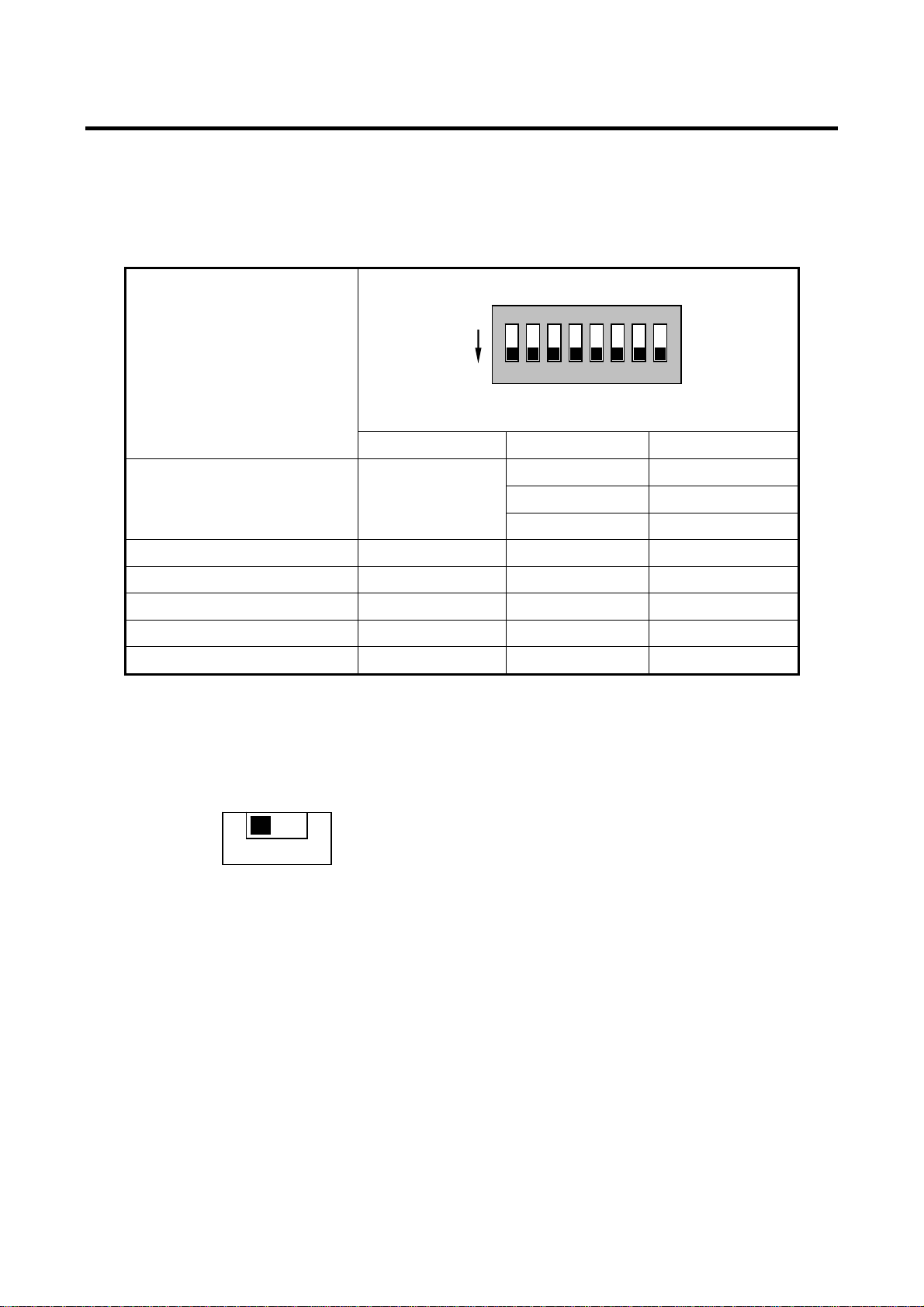
The SATA Mirror Drive's factory default settings are as follows:
● DIP Switch Settings
Default Setting
Enable
Function / Mode SW No. DIP SW SETTING
Normal Mode Mirror Mode
Reserved --- S4 OFF
Write Cache (Write Back) Enabled S5 OFF
Revival Reconstruction. Enabled S6 OFF
Buzzer Enabled S7 OFF
Reserved --- S8 OFF
● Status Output Signal Electrical:3.3V
.
V
S3
3.3V Output
.
V
ON
1 2 3 4 5 6 7 8
All OFF
S1 OFF
S2 OFF
S3 OFF
24
Page 36
3.5" Form Factor Mirror Drive SATA Model User's Manual
Appendix-D Replacement Parts
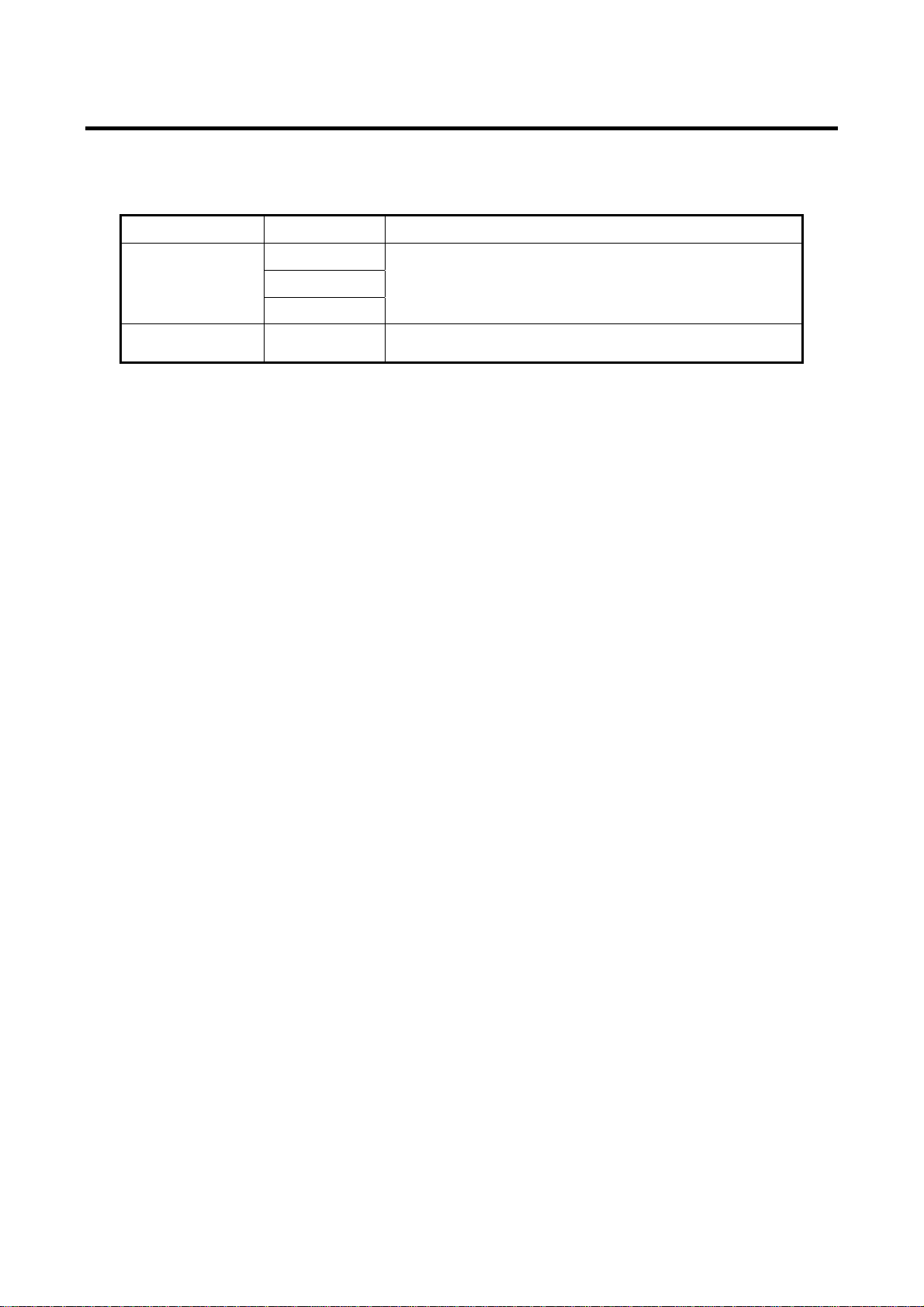
The following are supplied as user-replaceable parts.
Part name Part number
A203791
80 GB drive unit Replacement drive unit for AXRE-U080SA/SA1/SA2.
Controller unit A203807
A203945
A204059
Replacement controller unit for AXRE-U Serial ATA
series.
25
Page 37
3.5" Form Factor Mirror Drive SATA Model User's Manual
Information
For more information about this product, please contact your distributor.
Distributor’s information
● Product Records
Model Name
Revision
Serial Number
● Manufacturer
This product is manufactured by
Storage Vision Co., Ltd. Japan.
http://www.str-v.com/index_e.html
AXRE-U
YB-
26
 Loading...