

Structural Concepts NR3633RSV, NR3640RSV, NR3647RSV, NR3655RSV, NR4833RSV Installation & Operating Manual
...Page 1

READ AND SAVE THESE INSTRUCTIONS
INSTALLATION
& OPERATING
SCC P/N
20-80692
MANUAL
REVEAL™ FREE STANDING SERVICE REFRIGERATED MERCHANDISERS
> REAR SLIDING DOORS > SELF-CONTAINED OR REMOTE UNITS
> CAUTION! DO NOT PUSH OR PULL ON UPPER GLASS ENCLOSURE!
> ONLY USE HANDLES (AT EACH END OF CASE) TO PUSH OR PULL CASE INTO POSITION!
> SEE PAGE 3 FOR THIS OPERATING MANUAL’S MODEL APPLICABILITY AND DIMENSIONS
> SEE PAGE 8 FOR FRONT PANEL, SIDE CLADDING, AIR INTAKE GRILLE & FRONT TOE-KICK
ATTACHMENT INSTRUCTIONS
Models Are Shipped WITHOUT Panels
and Cladding Attached. See Page 8 For
Component Attachment Instructions.
Model NR3655RSV Free Standing Unit Shown
Before Front/Side Cladding and Toe-Kick
Have Been Attached
Structural Concepts Corporation · 888 E. Porter Road · Muskegon, MI 49441 Phone: 231.798.8888 Fax: 231.798.4960 · www.structuralconcepts.com
I:\Manuals\Reveal_Free Standing_Refrig Service Cases 20-80692.pub
Model NR3655RSV Free Standing Unit
Shown After Front/Side Cladding and
Toe-Kick Have Been Attached
Rev A Date: 6.13.2017
Page 2

TABLE OF CONTENTS
TABLE OF CONTENTS …………………………………………………………………………………...…...
REVEAL™ FREE STANDING REFRIGERATED SERVICE MODEL APPLICABILITY &
DIMENSIONS ……………………………………………………………………………………….…..
OVERVIEW / DISPLAY TYPE I vs. II / COMPLIANCE / WARNINGS / PRECAUTIONS ……………...
INSTALLATION: TOE-KICK & AIR INTAKE GRILLE REMOVAL / DISCONNECTING CA SE FROM
PALLET ...…...………………………………………………………………………………….……….
INSTALLATION, CONT’D.: CASTER ADJUSTMENT / LOCK / UNLOCK / CA SE REMOVAL
FROM PALLET .………………………………………………………………………………...……...
INSTALLATION, CONT’D: REMOVE SHIPPING BRACE AND HANDL ES / ATTACH
COMPONENTS (CLADDING, FRONT TOE-KICK, FRONT PANEL, GRILLE, ETC.) ..……….
INSTALLATION, CONT’D: BRACKET RETAINERS / SHELVING ASSEMBLY COMPONENTS ...…
INSTALLATION, CONT’D: PLUG IN UNIT / MAIN POWER SWITCH ...……………………………..….
CASE DESIGN: FRONT VIEW OF FREE STANDING, SERVICE MERCHANDISERS .......................
CASE DESIGN: REAR VIEW OF FREE STANDING, SERVICE MERCHANDISERS …..…………….
CASE DESIGN, CONT’D: CONTROLLER / DC DRIVERS / MAIN POWER SWITCH /
CONDENSER COIL FILTER ….………………………………………………………………………
CASE DESIGN, CONT’D: TUB AREA (AFTER DECK PAN REMOVAL) ……………………………….
CASE DESIGN, CONT’D: LED LIGHTS / LED LIGHT SWITCH / THERMOMETER ………………….
CASE DESIGN, CONT’D: REAR SLIDING DOOR REMOVAL / REPLACEMENT ……….……………
CASE DESIGN, CONT’D: CONDENSER PACKAGE (SELF-CONTAINED UNITS ONLY) …………..
PRODUCT PLACEMENT / AIRFLOW CONSIDERATION / LOAD LINES ……………………………...
CLEANING SCHEDULE (TO BE PERFORMED BY STORE PERSONNEL) ..…....…...…………...….
PREVENTIVE MAINTENANCE (TO BE PERFORMED BY TRAINED SERVICE PROVIDER) ……....
TROUBLESHOOTING (TO BE PERFORMED BY STORE PERSONNEL ONLY) ...………………......
TROUBLESHOOTING (TO BE PERFORMED BY TRAINED SERVICE PROVIDERS ONLY) ……….
TROUBLESHOOTING (TO BE PERFORMED BY TRAINED SERVICE PROVIDERS ONLY) CONDENSING SYSTEM ..………………………………………………………………………...….
TROUBLESHOOTING (TO BE PERFORMED BY TRAINED SERVICE PROVIDERS ONLY) EVAPORATOR SYSTEM ...…………………………………………………………………………...
SERIAL LABEL INFORMATION & LOCATION ..…………………………….……...…....……………..…
TEMPERATURE CONTROLLER - CAREL® ...…..……………………..…….……………………..……..
TECHNICAL SERVICE CONTACT INFORMATION & WARRANTY INFORMATION ...…...…...….....
2
3
4-5
6
7
8
9
10
11
12
13
14
15
16
17
18
19
20-21
22-23
24-26
27
28
29
30-32
33
2
Page 3

REVEAL™ FREE STANDING REFRIGERATED SERVICE MODEL APPLICABILITY & DIMS.
Model
Upper Display
Case Height
Overall Case Height Case Depth x Width
NR3633RSV 13 5/8” 32 7/8” 33”D* x 35 3/4”W
NR3640RSV 20 3/8” 39 5/8” 33”D* x 35 3/4”W
NR3647RSV 27 7/8” 47 1/8” 33”D* x 35 3/4”W
NR3655RSV 35 1/4” 54 5/8” 33”D* x 35 3/4”W
NR4833RSV 13 5/8” 32 7/8 33”D* x 47 3/4”W
NR4840RSV 20 3/8” 39 5/8” 33”D* x 47 3/4”W
NR4847RSV 27 7/8” 47 1/8” 33”D* x 47 3/4”W
NR4855RSV 35 1/4” 54 5/8” 33”D* x 47 3/4”W
3
Page 4

OVERVIEW / DISPLAY TYPE I vs. II / COMPLIANCE / WARNINGS / PRECAUTIONS - PAGE 1 of 2
OVERVIEW
These Structural Concepts Reveal™ cases are
designed to merchandise packaged products at 40°F
(4 °C) or less product temperatures.
Cases should be installed and operated according to
this operating manual’s instructions to insure proper
performance. Improper use will void warranty.
TYPE I vs. TYPE II ENVIRONMENTAL CONDITIONS
This unit is designed for the display of products in
ambient store conditions where temperature and
humidity are maintained within a specific range.
Type I display refrigerators are intended for use in an
area where environmental conditions are controlled
and maintained so that the ambient temperature does
not exceed 75 °F (24 °C) and 55% maximum humidity.
Type II display refrigerators are intended for use in an
area where environmental conditions are controlled
This equipment MUST be installed in compliance with
all applicable NEC, federal, state and local
ATTENTION
CONTRACTORS
and maintained so that the ambient temperature does not
exceed 80 °F (27 °C) and 55% maximum humidity.
If unsure if your unit is Type I or II, see tag next to serial
label. See SERIAL LABEL LOCATION &
INFORMATION LISTED / TECH INFO & SERVICE
section in this manual for sample serial labels.
COMPLIANCE
Performance issues when in violation of applicable
NEC, federal, state and local electrical and plumbing
codes are not covered by warranty.
See below compliance guideline.
WARNINGS
Please read the important warnings in this document
carefully as they can prevent injury or death.
See next page for PRECAUTIONS.
COMPLIANCE
electrical and plumbing codes.
WARNING
ELECTRICAL
HAZARD
WARNING
KEEP
HANDS
CLEAR
WARNING
Risk of electric shock. Disconnect power before servicing unit.
CAUTION! More than one source of electrical supply is
employed with units that have separate circuits.
Disconnect ALL ELECTRICAL SOURCES before servicing.
WARNING
Hazardous moving parts. Do not operate unit with covers removed.
Fan blades may be exposed when deck panel is removed.
Disconnect power before removing deck panel.
CAUTION! IF YOUR UNIT IS SELF-CONTAINED, YOU MUST
CHECK CONDENSATE PAN POSITION & PLUG!
Water on flooring can cause extensive damage!
Before powering up unit, check and confirm that:
Condensate pan is DIRECTLY UNDER condensate drain.
Condensate pan plug is securely plugged into receptacle.
Overflow pan has plug connected to its box. Units with
optional Clean Sweep® MUST HAVE two plugs connected.
4
Page 5

OVERVIEW / DISPLAY TYPE I vs. II / COMPLIANCE / WARNINGS / PRECAUTIONS - PAGE 2 of 2
PRECAUTIONS
Following are important precautions to prevent
damage to unit or merchandise.
Please read carefully!
CAUTION! LAMP REPLACEMENT GUIDELINES
CAUTION
LED lamps reflect specific size, shape and overall design.
Any replacements must meet factory specifications.
CAUTION! GFCI BREAKER USE REQUIREMENT
If N.E.C. (National Electric Code) or your local code
requires GFCI (Ground Fault Circuit Interrupter) protection,
you MUST use a GFCI breaker in lieu of a GFCI receptacle.
WIRING DIAGRAM
Each case has its own wiring diagram folded and in its own
packet.
Wiring diagram placement may vary (near ballast box, field
wiring box, raceway cover, or other related location).
CAUTION
CAUTION! ADVERSE CONDITIONS / SPACING ISSUES
Performance issues caused by adverse conditions are NOT covered
by warranty.
End panels must be tightly joined or kept at least 6-inches away from
any structure to prevent condensation.
Unit must be kept at least 15-feet from exterior doors, overhead HVAC
vents or any air curtain disruption to maintain proper temperatures.
Unit must not be exposed to direct sunlight or any heat source (ovens,
fryers, etc.).
CAUTION!
DO NOT RELY ON THERMOMETERS OR THERMOSTATS
FOR ACTUAL PRODUCT (FOOD) TEMPERATURES.
Thermometers and thermostats reflect air temperatures ONLY.
For PRECISE food temperatures, use calibrated food
thermometers only.
WIRING DIAGRAM FORMAT & LOCATION
Each case has its own wiring diagram folded & in its own packet.
Wiring diagram placement may vary; it may be placed near field
wiring box, raceway, or other related location.
5
Page 6

INSTALLATION: TOE-KICK & AIR INTAKE GRILLE REMOVAL / DISCONNECTING CA SE FROM PALLET
1. Remove Front Toe-Kick From Case
To prevent damage to case, remove front
toe-kick from case before removing from pallet.
Toe-kick is held in place by magnets only. No
screw removal is required.
Place front toe-kick in secure location while
removing case from pallet.
2. Remove Air Intake Grille From Case
To prevent damage to case, if air intake grille is
on the case, lift it UP and OFF.
Air Intake Grille
Front Toe-Kick
Air intake grille is held in place by magnets.
No screw removal is required.
Place air intake grille in secure location
while removing case from pallet.
3. Disconnect Case From Pallet
Remove screws from shipping
brackets. Remove and discard
shipping brackets from pallet.
Place J-bar/pry under base frame.
Raise case up from pallet to take
weight off casters.
With case raised, lower casters all the
way down against pallet (see next
step for detailed instructions on
lowering or raising casters).
Remove rubber shipping blocks.
6
Pallet Rubber Shipping Block Shipping Bracket
Page 7

INSTALLATION, CONT’D.: CASTER ADJUSTMENT / LOCK / UNLOCK / CA SE REMOVAL FROM PALLET
4. Caster Height: Raising and Lowering
Raise or lower casters (to adjust case height) by
rotating casters’ vertical adjustment rings.
Rotate vertical adjustment ring clockwise to lower
Vertical
Adjustment
Ring
caster (and increase height of case).
Rotate vertical adjustment ring counter-clockwise
to raise caster (and decrease height of case).
Caster
5. Caster Rolling Capability: Unlocking
Important! Case is shipped with caster mechanisms
factory set at ON (locked) to prevent case from rolling.
Unlock casters by pressing OFF on the caster
mechanism.
See illustration at right.
6. Carefully Remove Case From Pallet
Check that casters are lowered as far down as they
will go (as instructed in step #4).
Use handles to carefully slide case to rear of pallet
(see illustration at right).
Carefully lower to floor. Slide pallet from under case.
Maintain support of case at all times or center
of gravity may cause case to fall.
Press “OFF” Lever To
Unlock Casters (And
Allow Casters To Roll)
Pallet
Caster
Support case
while removing
from pallet
Handles
7. Casters: Locking
After case is at desired position (and height),
use level to check that case is level and plumb.
Readjust height as needed (as instructed in step #4).
Locking Height: After proper height (and positioning) of
case is attained, tighten the two (2) set screws to lock
each caster’s height in place.
Locking Movement: Then, to prevent casters’ rolling
capability, lock casters by pressing ON atop the “ON”
and “OFF” lever mechanism (shown at right). Case
will now be secured at its new location.
Press “ON” Lever To
Lock Caster In Place
(And Prevent Casters’
Rolling Capability)
Tighten Set
Screws To
Lock Caster
Height In
Place
Caster
7
Page 8

INSTALLATION, CONT’D: REMOVE SHIPPING BRACE AND HANDL ES / ATTACH COMPONENTS
8. Remove Handles On Sides of Case
When case has been moved into position, remove
handles from both sides of case (shown below).
9. Remove Shipping Brace
Shipping brace keeps condenser package secure
during shipment and while positioning case.
After case is in position, remove shipping brace
that is just below condenser package.
Note: Whether Condenser Package Access Is
At Rear (As Illustrated Below) or Front, Shipping
Brace Is ONLY
To Be Removed From Condenser
Package Access Side of Case!
10. Attach Components
Important! Attach front panel to case first!
To do so, slide center bracket (attached to front
panel) atop case’s front panel support bracket.
Important! Attach Front Panel To Case First!
Side Cladding
Then, slide panel into case until magnets attach
to case in flange’s cutout openings (as shown).
Other components to be attached: side cladding,
panel base front kick and air intake grille
After case is in position, all components may be
attached to case WITHOUT screw attachments.
Then, attach side cladding to magnets.
Finally, air intake grille and toe-kick may then be
attached to case.
Components use hook/slot/magnet attachment
method for secure retention.
Carefully remove from packaging.
Grasp each component firmly and carefully
install as illustrated below.
Model NR3640RSV Free Standing Unit
(Shown) May Not Exactly Reflect Every
Feature or Option of Your Particular Case.
Air Intake
Grille
Front
Panel
Front Toe-Kick
Note: Shipping Brace That Is Opposite
To Condenser Package Access Side
Of Case Is NOT
To Be Removed!
8
Handles (Typ.)
Shipping Brace
Side
Cladding
Page 9

INSTALLATION, CONT’D: BRACKET RETAINERS / SHELVING ASSEMBLY COMPONENTS
11. Nylon Shipping Bracket Retainers
Retainers keep shelving secure during shipping.
There are two shipping bracket retainers per side.
To adjust or remove shelves you must remove
nylon shipping bracket retainers.
Pliers may be required to accomplish this task.
See illustration below for locations.
12. Shelving Assembly Components
Check that glass shelving is in proper position
before placing product in case
Shelves may be adjusted vertically or entirely
removed from merchandiser.
Metal shelving bracket ARE NOT able to be
angled. They are at a fixed 90°.
Nylon
Shipping
Bracket
Retainer
(Typical)
From Factory: Transparent 2-Sided
Tape Holds Glass To Top Of Rear
Shelf Support Rail
There are eight (8) components comprising each
shelf assembly:
1. Right bracket (with hooks to attach to slots in
upright)
2. LED light with magnets
3. Front shelf support rail (LED light attaches to its
inner cavity via magnets)
4. Cover (rests atop front shelf support rail)
5. Left bracket (with hooks to attach to slots in upright)
6. Rear shelf support rail
7-8. Left and right glass shelf/cover assemblies
(glass is affixed to covers with 2-sided tape).
6
7
Glass Shelving
5
Glass Shelving
8
1
2
3
4
9
Page 10

INSTALLATION, CONT’D: PLUG IN UNIT / MAIN POWER SWITCH
13. Plug Case In / Turn Main Power Switch On
Power cord with plug is factory-supplied.
Plug case into customer-supplied electrical outlet.
Note 1: Partially-disassembled view at right is
shown with casters removed for illustrative
purposes only. View/location of floor receptacle is
for illustrative purposes only.
Note 2: Due to space constraints, it may be
necessary to pull out condenser package to
maneuver power cord plug around components
and into receptacle.
Turn main power switch on.
Check that case is energized. Lift deck pans to
confirm that evaporator fans are rotating).
Turn on LED light switch at front-left header.
Factory-Supplied Power
Cord With Plug
Customer Supplied Receptacle
(Sample Floor Unit Illustrated).
: Casters Removed For
Note
Illustrative Purposes Only.
Main Power
Switch
10
Page 11
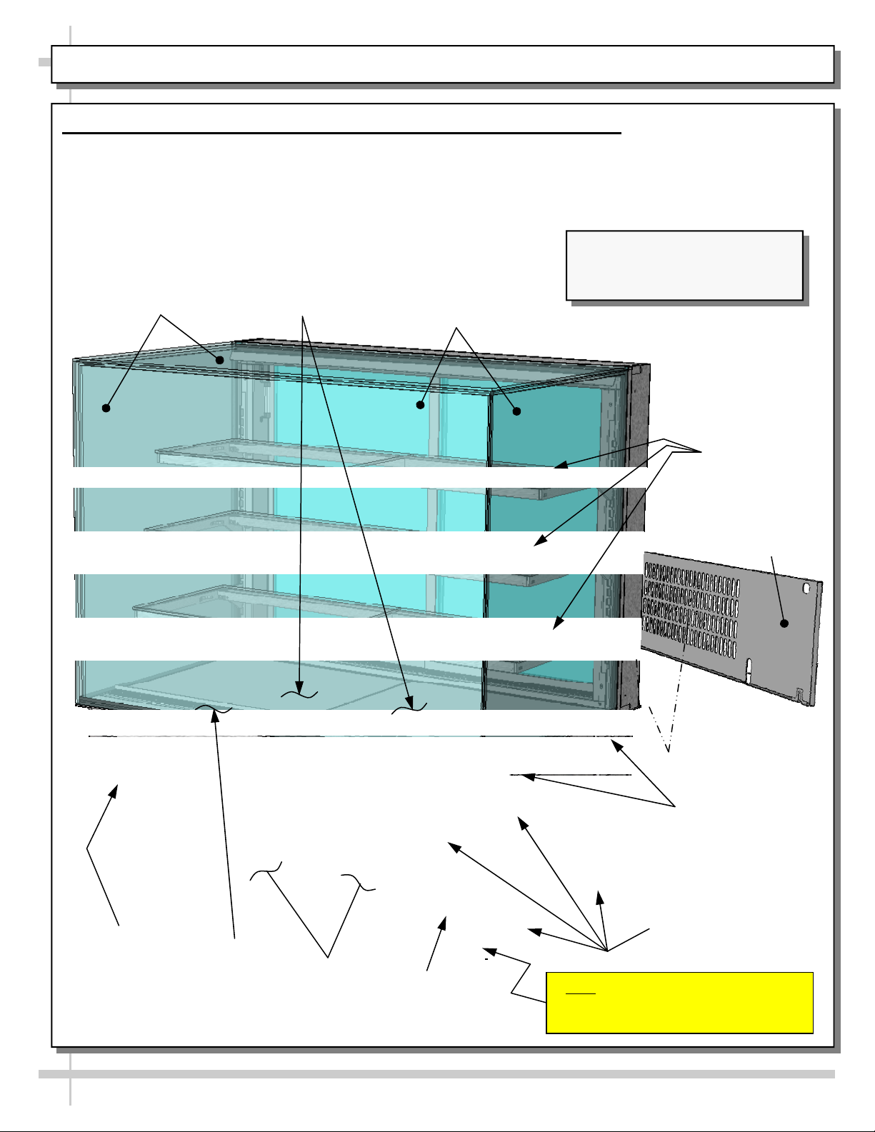
CASE DESIGN: FRONT VIEW OF FREE STANDING, SERVICE MERCHANDISERS
1. Case Design: Front View Of Free Standing, Service Merchandisers
Model NE3635RSV is illustrated below.
Air intake grille, side cladding, front base kick & front panel have been removed for illustrative purposes
only.
See next page for rear view.
Model NR4855RSV (Shown) May
Not Exactly Reflect Every Feature
UV-Bonded Glass
Enclosure (Typ.)
Decking
Rear Sliding
Doors
or Option of Your Particular Case.
Shelving (Typ.)
Magnet For Front
Panel And Side
Cladding (Typ.)
Air Return
Condenser
Package
Caster (Typ.)
Air Intake
Grille
Handles For
Pushing or Pulling
Unit Into Position
Magnet For Front
Panel And Side
Cladding (Typ.)
Note: Do Not Remove The Shipping
Brace That Is Opposite The Condenser
Package Access Side Of Case
11
Page 12
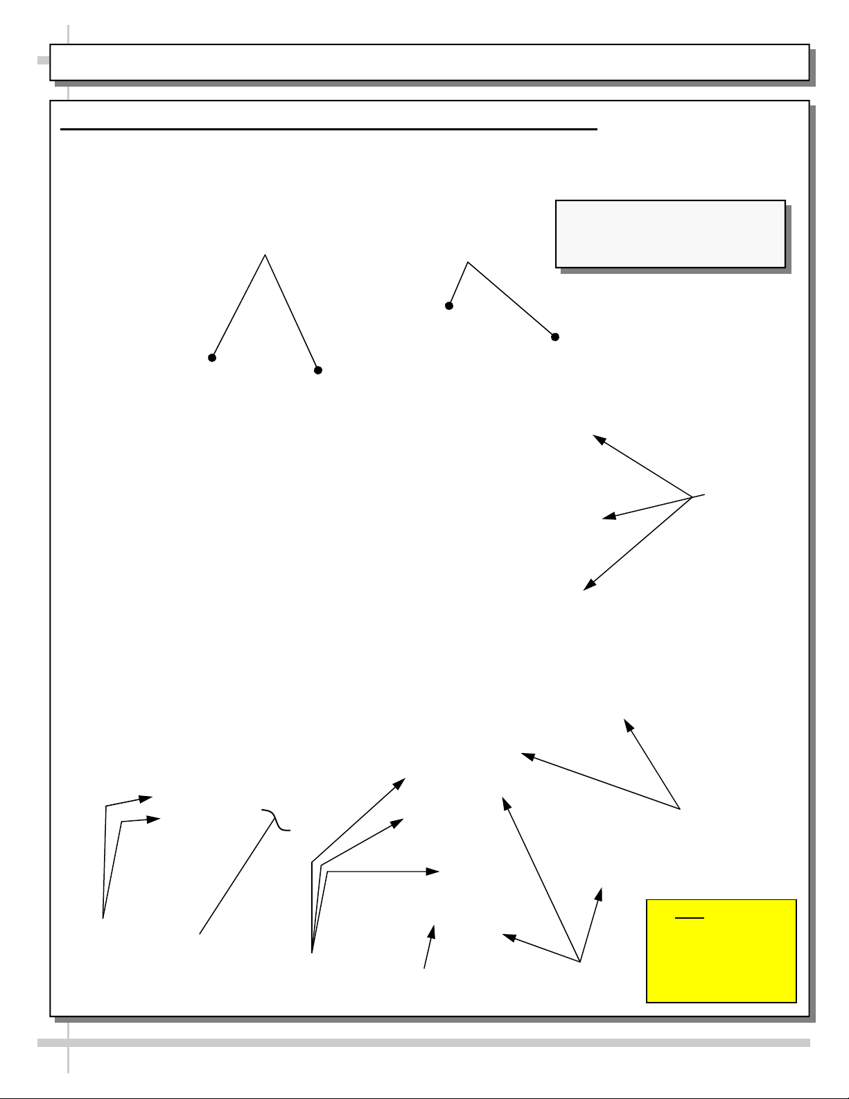
CASE DESIGN: REAR VIEW OF FREE STANDING, SERVICE MERCHANDISERS
2. Case Design: Rear View Of Free Standing, Service Merchandisers
Model NR4855RSV free standing unit is illustrated below.
Air intake grille, rear panel, side cladding & shipping brace have been removed for illustrative purposes
only.
Rear Sliding
Doors
UV-Bonded Glass
Enclosure (Typ.)
Model NR4855RSV (Shown) May
Not Exactly Reflect Every Feature
or Option of Your Particular Case.
Shelving
(Typ.)
Thermostat
and Main
Power Switch
Condenser
Package
Magnets For Rear
Panel And Air In-
take Grille
Caster (Typ.)
12
Magnets For Side
Cladding (Typ.)
Handles For
Moving Unit
(Typ.)
Note: Only The
Shipping Brace That Is
Below The Condenser
Package Access Side
Of Case (Shown) Is To
Be Removed!
Page 13
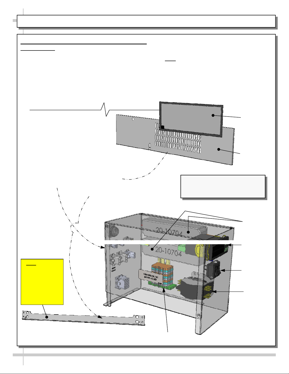
CASE DESIGN, CONT’D: CONTROLLER / DC DRIVERS / MAIN POWER SWITCH / COIL FILTER
3. Case Design: Controller / DC Driver Access /
Components
Remove front panel by lifting up and off; no screw
removal is required.
Magnetic condenser coil filter is directly accessible.
See CLEANING SCHEDULE (TO BE PERFORMED
BY STORE PERSONNEL) for cleaning instructions.
Remove shipping brace by loosening two (2)
shoulder screws.
Remove 4 screws from the controller/DC
driver box cover to access electrical
components.
Note: Only certified electricians are to access
electrical components in case.
After accessing controller and/or DC drivers,
return components to case in reverse order
they were removed.
Magnetic
Condenser
Coil Filter
Panel Base
Front Kick
Note: Only The
Shipping Brace
That Is Below The
Condenser
Package Access
Side Of Case
(Shown) Is To Be
Removed!
Free Standing Unit (Shown) May Not
Exactly Reflect Every Feature or
Option of Your Particular Case.
DC Drivers
Thermostat
Main Power
Switch
Contactor
Terminal Block
13
Page 14
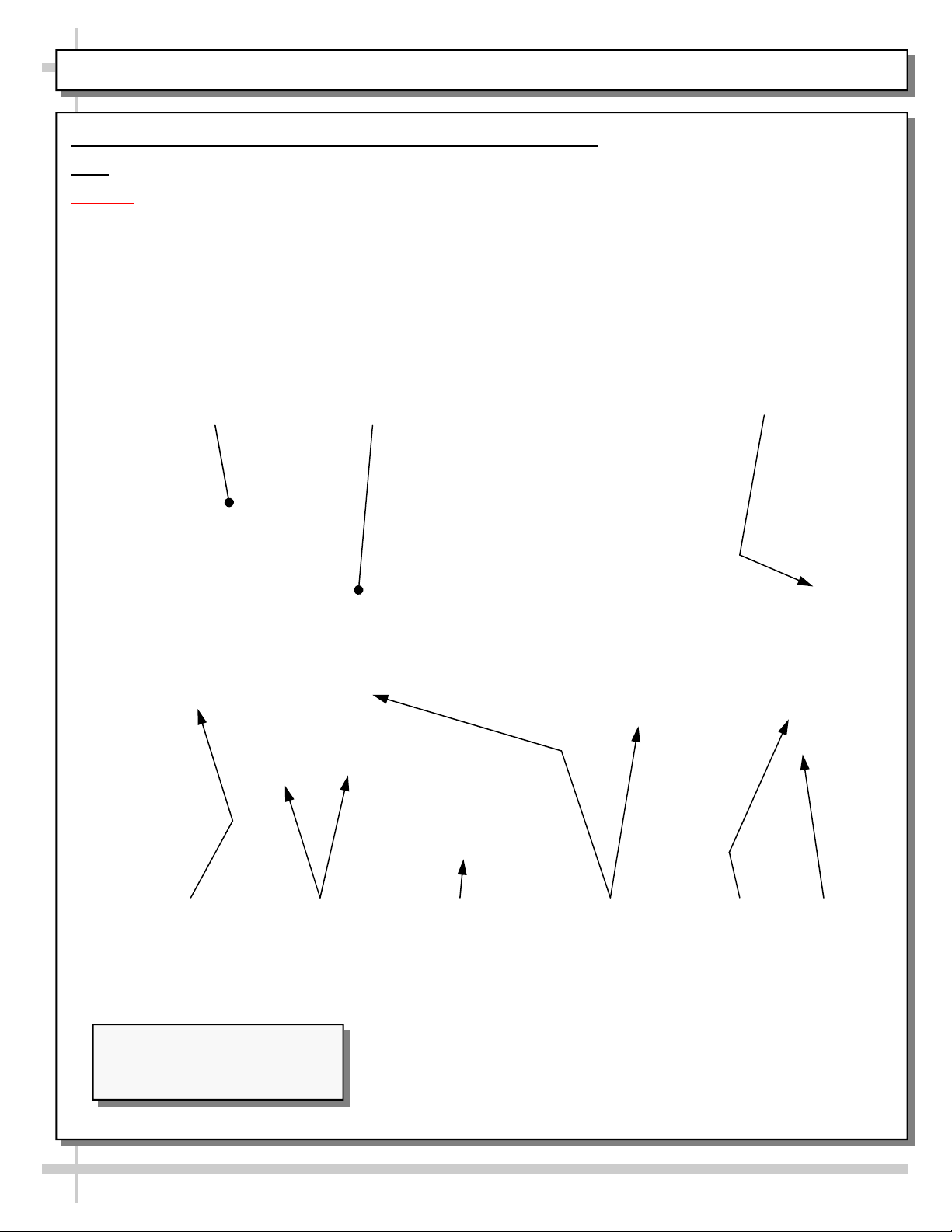
CASE DESIGN, CONT’D: TUB AREA (AFTER DECK PAN REMOVAL)
4. Case Design, Cont’d: Tub Area (After Deck Pan Removal)
Note: Refrigeration service to be accomplished by refrigeration / electrical contractors only.
Caution! Turn main power off before accessing tub area.
Illustration below shown after removal of deck pans.
After cleaning or servicing in tub area, return deck pans to case and return power to case.
Air Discharge
Evaporator
Coil Cover
--- Case Rear ---
Evaporator
Coil
Refrigeration
Line Route
Lines
Note: Internals Shown May Not
Exactly Reflect Every Feature or
Option of Your Particular Case.
Acrylic Return
Airflow Deflector
--- Case Front ---
14
TXV Evaporator Fans Refrigeration
Drain
Page 15
CASE DESIGN, CONT’D: LED LIGHTS / LED LIGHT SWITCH / THERMOMETER
5. Case Design, Cont’d: LED Lights / LED
Light Switch
LED lights are located at both header and
shelving of case.
See illustrations below.
Note: For step-by-step change-out instructions,
see MAINTENANCE, CONT’D: LED STYLE
LIGHT FIXTURES section in this operating
manual.
6. LED Light Switch
LED light switch is at rear-right header (as shown
in below-left illustration).
You must slide rear-right door open to access
LED light switch.
Light Switch
7. Thermometer Function & Placement
Thermometer provides temperature of
refrigerated section of case.
Thermometers reflect warmest air
temperature in merchandiser. They do not
provide actual food temperature.
Use probe thermometers to determine actual
product temperatures.
LED Light Fixture
Thermometer
Top Shelf
Middle Shelf
Lower Shelf
15
Page 16
CASE DESIGN, CONT’D: REAR SLIDING DOOR REMOVAL / REPLACEMENT
8. Rear Sliding Door Removal / Replacement
To remove rear sliding doors, move rear doors toward center of the case.
Individually lift each door up toward the top of the case; pivot the bottom of the door out.
Return doors to case in reverse order they were removed.
16
Model NR3635RSV Free Standing
Unit (Shown) May Not Exactly
Reflect Every Feature or Option of
Your Particular Case.
Page 17
CASE DESIGN, CONT’D: CONDENSER PACKAGE (SELF-CONTAINED UNITS ONLY)
9. Condenser Package (Self-Contained Units
Only)
Assembly/disassembly and servicing to be
performed by licensed refrigeration contractor.
Optional Clean
Sweep® Condenser
Coil Cleaning
System
Evaporator
Section
Drain PVC
Condenser Coil
Fans & Motors
Condensate Package Configuration
Illustration shown is from model NR3635RSV.
Your unit’s component layout may slightly vary.
Condenser Coil
Housing
Refrigeration
U-Tubes
Filter Dryer
Overflow
Condenser Pan
(With Electric Coil)
Sight Glass
Condenser Package From Model
NR3635RSV Free Standing Unit (Shown)
May Not Exactly Reflect Every Feature or
Option of Your Particular Case.
Controller
DC Driver
Hot Gas Loop
Condensate Pan
Compressor
17
Page 18
START-UP AND OPERATION, CONTINUED: LOAD LIMITS
PRODUCT PLACEMENT / AIRFLOW CONSIDERATION / LOAD LINES
1. Product Placement
Product can be placed on decking or steps
(risers) within the service display area.
A wide range of product may be displayed.
2. Air Diffuser Grille & Return Air Grille
Considerations
Proper airflow is critical to maintain proper
product temperature.
Proper product placement will allow rear air to
flow over (and around) product to return air grille
at case front. See illustration below for specifics.
Model NR3655RSV) Shown Below
Caution! For airflow to reach return air grille, you
must not block front or rear grilles with product.
Do not place product on front ledge of case.
3. Load Lines
Load lines represent the limit that product can be
place (either horizontally or vertically) and/or
stacked in case.
Keep product at or under load lines to assure that
refrigerated airflow is properly cycled from air
diffuser through return air grille.
Proper product placement will maintain
acceptable product temperature.
See illustration below.
1” Minimum
Load Line
1” Minimum
Load Line
Model NR3655RSV (Shown)
May Not Exactly Reflect Every
Feature or Option of Your
Particular Case. However,
General Airflow Consideration
and Load Line Guidelines Apply.
Load Lines
Sample
Product (Typ.)
Diffuser Grille. Do Not Block!
Caution! Convertible 1.25” Air
1” Minimum
Load Line
1” Minimum
Load Line
Caution!
Do Not Place
Product On
Return Air Grille
Or Ledge
Product Stop
Load Lines
Angled View Of
Return Air Grille
18
18
Page 19
CLEANING SCHEDULE (TO BE PERFORMED BY STORE PERSONN EL)
FREQ. INSTRUCTIONS
Daily
Daily
Glass Surfaces: Clean side glass and shelves with household or commercial glass cleaner.
Rear Sliding Door Exterior Glass: Clean with household or commercial glass cleaner. Clean
out rear door track with moist cloth.
Daily
End Panels, Front Panel, Toe-Kick, etc.: Wipe off all surfaces with warm water and mild soap
solution and non-abrasive cloth.
Daily
Daily
Decks: Wipe off decks with moist cloth dipped in mild soap and water solution.
Acrylic Air Deflector: Clean with warm water, mild soap solution and soft cloth; acrylic
cleaning solutions are also available. Caution! Never use ammonia-based cleaners on acrylic.
Incorrect cleaning agents or abrasive cleaning cloths cause surface to ‘cloud’ over time.
Weekly
Optional: Rear Acrylic Perforated Plenums: Clean with warm water, mild soap solution and
soft cloth; acrylic cleaning solutions are also available. Caution! Never use ammonia-based
cleaners on acrylic. Incorrect cleaning agents or abrasive cleaning cloths cause surface to
‘cloud’ over time.
Weekly Magnetic Condenser Coil Filter (Self-Contained Units Only):
This filter helps prevent dust particles from entering condenser coil.
It is accessible at air intake side of case.
Clean magnetic condenser coil filter by following either step 1 or 2; then follow step 3:
1. As magnetic condenser coil filter is dishwasher safe, remove from case (no screw
removal required) and use a rag or soft-bristled brush to wipe off excess dust particles
from filter. Run in normal dishwasher cycle. Remove from dishwasher. Dry with soft cloth
or paper towel. Return to case.
2. If not using dishwasher, remove magnetic condenser coil filter from case. Use a rag or
soft-bristled brush to wipe off excess dust particles from filter. Submerse in warm, soapy
water. Use soft-bristled brush to remove dust, dirt, grease and grime that may collect on
filter. Rinse thoroughly.
3. Dry with soft cloth or paper towel (as shown below) or allow to air dry. Replace.
Monthly
Under Case Cleaning
: Remove toe-kick (or air intake grille). Vacuum under case to remove all
dust and dirt. Replace toe-kick (or air intake grille) when complete.
19
Page 20
PREVENTIVE MAINTENANCE (TO BE PERFORMED BY TRAINED SERVICE PROVIDER) - PAGE 1 OF 2
WARNING! TURN OFF CASE BEFORE PERFORMING PREVENTIVE MAINTENANCE!
FREQ. INSTRUCTIONS
Quarterly Condensing Coil:
Remove air intake grille to access area. Simply lift up and off.
Roll/slide out condenser package. Note: At initial slide-out, it may be necessary to remove
two (2) compressor pan shipment screws to slide it out from under case.
Warning! Coil fins are sharp. Handle with care!
Caution! Airborne dust can contaminate food! Use wet rags to cover area where air
pressure is blowing.
Use air pressure or industrial strength vacuum; clean dust and dirt that may collect on
condenser coil.
Slide/roll condensing package back under case.
Return air intake grille to case.
Quarterly Condenser Package: Caution! Disconnect power from case before cleaning!
See CASE DESIGN, CONT’D: CONDENSER PACKAGE (SELF-CONTAINED UNITS
ONLY)
Warning! Condensate pan may be HOT! Disconnect power from case and allow to cool
section in manual for illustrations.
before cleaning condensate pan!
Remove air intake grille from case (no screw removal is required).
Slide/roll condenser package out from under case.
Use a scrub-brush and a de-scaling solution such as CLR® (to prevent corrosion, lime and
rust). Follow instructions as to proper dilution, safety precautions and scrubbing method.
If electric coil overflow condensate pan is dirty, clean it (and in same manner) while cleaning
rest of condenser package.
After thoroughly cleaning condensate pan with scrub-brush and solution, rinse thoroughly
with clean water (in spray bottle) and wipe dry with sponge or paper towel.
Use moist cloth to wipe off dust & debris that collects on various parts (fans, sight glass,
overflow pan, etc.).
Slide condenser package back under case.
Return air intake grille to case (no screws required).
Quarterly Under Case Cleaning: Once refrigeration package is clear of unit, vacuum under case to
remove dust and dirt that may collect under case.
Quarterly Tub Area (Evaporator Coil, Drain, Fans, Brackets, Etc.):
Caution! Disconnect power from case before cleaning tub, coil, fan, motor and drain area!
See CASE DESIGN, CONT’D: TUB AREA (AFTER DECK PAN REMOVAL) section in
manual for illustration.
Use vacuum to clean entire area.
After vacuuming, clean area with warm water, clean cloth, and mild soap solution.
Remove any debris that may clog drain.
Wipe down fan blades, motors and brackets with moist cloth.
20
Page 21
PREVENTIVE MAINTENANCE (TO BE PERFORMED BY TRAINED SERVICE PROVIDER) - PAGE 2 OF 2
FREQUENCY INSTRUCTIONS
Quarterly Optional Clean Sweep™ Condensing Coil Cleaner: Disconnect power from case
before servicing the Clean Sweep™ Condenser Coil Cleaner!
Remove air intake grille (by lifting up and off); no screw removal is required.
Slide/roll out condensing package from underside of case assembly.
Remove the four (4) screws holding the Clean Sweep™ rail intact.
Remove the Clean Sweep™ rail.
Wash rails’ brushes in hot water and mild soap solution.
If brushes are worn, they must be replaced. Call Technical Service Department to
replace. Toll-Free number is listed at end of manual.
Clean condensing coil: Use air pressure or industrial strength vacuum; clean the dust
and dirt that may collect on the condenser coil.
Caution! Coil fins are sharp. Handle with care!
Reattach Clean Sweep™ rail to condensing unit (4 screws).
Slide/roll condensing package back under case.
Replace air intake grille to case (4 screws).
See photos below.
ng
i
s
n
de
n
Co
(4) Screws
--- Above photos are taken after air intake grille has been removed from case ---
Coil
Brushes
Rail
21
Page 22
TROUBLESHOOTING (TO BE PERFORMED BY STORE PERSONNEL) - PAGE 1 OF 2
CONDITION TROUBLESHOOTING
Water Is On The Floor
Fan Emits Excessive Noise
Case Lights Are Not Working
Case is Not Holding Proper
Temperature
Call service provider.
Call service provider.
Check that light switch is in the on position.
Check that ALL of the light cords and plugs are properly connected.
See next page for step-by-step connection instructions and illustrations.
If case lights still do not come on, call service provider.
If a large amount of warm product was added to the case, it will take time
for the temperature to adjust. Product must be pre-chilled before placing
in case.
Check that the case is not in the sun or near a heat or air-conditioning
vent. See OVERVIEW / NSF® TYPE / COMPLIANCE / WARNINGS /
PRECAUTIONS section in this manual for specifics.
If case is located near outside doors, temperature fluctuation can hinder
unit’s ability to maintain temperature.
Check air return grilles (area at front of decking) for obstructions.
DO NOT set product on air grilles as this will prevent proper airflow!
If case still is not holding proper temperature, call service provider.
22
Page 23
TROUBLESHOOTING (TO BE PERFORMED BY STORE PERSONNEL) - PAGE 2 OF 2
LED Light Fixture Replacement
Light fixtures are located in header as well as in
shelving (as shown in illustrations below).
Warning! Disconnect power before providing
maintenance and service to unit.
Note: Warranty will be void if claims arise from
negligence, misuse of goods, extreme
environmental conditions or improper
maintenance.
Removal of lamp:
Certain cases have LED lights. LED lights rarely
require change-out.
Should malfunction occur, contact Structural
Concepts’ Technical Service Department for
replacement parts. See Technical Service
section of manual for contact information.
Replacement of lamp:
To replace LED Light Fixture, simply disconnect
the existing LED light from its brackets and/or
self-adhesive tape. Replace.
Note: LED light and plug must be connected in a
specific manner or they will not work.
Oval edge of plug must connect to oval edge of
LED light.
LED light energizes when case is powered up.
See illustrations at right an below.
LED’s
Oval Form
Plug’s
Oval
Form
LED Light Fixture
23
Page 24
TROUBLESHOOTING (TO BE PERFORMED BY TRAINED SERVICE PROVIDERS ONLY) - PAGE 1 OF 3
CONDITION TROUBLESHOOTING
Water Is On The
Floor
Caution! Disruption of power or malfunctioning condensate pan (or electric coil
overflow condensate pan) may cause water to overflow pan and seep onto flooring
causing damage! Until condensate pan(s) are functioning (or are replaced), follow
these procedures:
Use wet vacuum (or mop & bucket) to remove standing water.
Use ‘catch pans’ for water to drain into. Swap out regularly until case has
completely drained.
When power to case is restored, condensate pan should function properly and
water will no longer overflow onto flooring.
Check that the drain trap is free of debris.
Check that the drain PVC is correctly positioned over condensate pan.
Check store conditions. To prevent condensation in Type I environments, maximum
conditions are to be 55% humidity / 75° Fahrenheit. For Type II environmants,
maximum conditions are to be 60% humidity / 80° Fahrenheit. See serial label (near
main power switch) for NSF® Type of your case.
Check that electric coil overflow condensate pan is properly plugged in or connected.
24
Page 25
TROUBLESHOOTING (TO BE PERFORMED BY TRAINED SERVICE PROVIDERS ONLY), PAGE 2 OF 3
CONDITION TROUBLESHOOTING
Fans Emit
Excessive Noise
Fans Are Not
Working
Check that the case is aligned, level and plumb.
Check evaporator fans for cleanliness.
Unplug/power off fan motors. Check motor shaft for bearing wear.
Check that fan motors are securely mounted in brackets.
Verify that fan blades are securely mounted to fan motor.
Check that nothing is preventing blade rotation.
Check that the fan shroud is properly secured.
Check that the MAIN power switch is on.
System Not
Operating
Check that fans are plugged in at the fan shroud.
Check for foreign material obstructing fan performance.
Check that fan blades freely rotate within fan shrouds
Check that power is going to fans
Check that fan wiring is connected on terminal blocks.
Check that the utility power is on.
Check that the MAIN power switch is on.
Check the circuit breaker box for tripped circuits.
25
Page 26
TROUBLESHOOTING (TO BE PERFORMED BY TRAINED SERVICE PROVIDERS ONLY), PAGE 3 OF 3
CONDITION TROUBLESHOOTING
Case Lights Are
Not Working
Case Is Not
Holding
Temperature
Check that light switch is in the on position.
Check that ALL of the light cords and plugs are properly connected. See
TROUBLESHOOTING (TO BE PERFORMED BY STORE P ERSONNEL) - PAGE 2
OF 2 in operating manual for illustrations.
Service Technicians Only: Check voltage at LED drivers. If voltage is entering but not
exiting, LED driver may be faulty.
If a large amount of warm product was added to the case, it will take time for the
temperature to adjust. Unit needs product to be pre-chilled.
Temperature changes during defrost mode but will return to normal. Fourth LED will
indicate defrost cycle in progress.
Check that case is not in sun or near a heat or air-conditioning vent.
If case is located near outside doors, temperature fluctuation can hinder unit’s ability
to maintain temperature.
Check that condenser coil has been cleaned.
Check that magnetic air filter (attached to air intake grille) has been cleaned.
See CLEANING SCHEDULE (TO BE PERFORMED BY STORE PERSONNEL)
section in operating manual for instructions.
Digital Control
Display Is Blank
System Is Not
Operating
Condensing Unit
Is Not Operating
Check return air grilles for obstructions.
Check sight glass for flashing and/or low charge.
Check set point temperature; it may be adjusted too high.
Check that the MAIN power switch is on.
Check the circuit breaker box for tripped circuits.
Check that the utility power is on.
Check that the MAIN power switch is on.
Check the circuit breaker box for tripped circuits.
Check that the power is turned on.
Determine if temperature controller settings are properly set. See your case’s serial
label for your model’s specified settings. See SERIAL LABEL LOCATION &
INFORMATION LISTED / TECH INFO & SERVICE section in manual for specifics.
26
Page 27
TROUBLESHOOTING (BY TRAINED SERVICE PROVIDERS ONLY) - CONDENSING SYSTEM
CONDITION TROUBLESHOOTING
Head Pressure
Too High
Check that the condensing coil is not dirty or covered.
Check that condensing fans are working.
Check that refrigerant is not overcharged.
Perform sub-cooling check and verify that no contaminates are in system.
Check that liquid line filter dryer is not plugged.
Check that close-offs are intact (around condensing coil) and that air is not
recirculating.
Head Pressure
Too Low
Check that store ambient temperature isn’t above maximum allowed. See
OVERVIEW / TYPE / COMPLIANCE / WARNINGS / PRECAUTIONS / WIRING /
PLUGS section in this manual.
Check if sight glass is flashing or showing low charge.
Check that suction pressure isn’t too low.
Check that compressor reed valves aren’t bad. Look for high suction/low head
pressure. Perform pump-down.
27
Page 28
TROUBLESHOOTING (BY TRAINED SERVICE PROVIDERS ONLY) - EVAPORATOR SYSTEM
CONDITION TROUBLESHOOTING
Low Suction
Pressure
High Suction
Pressure
Check if sight glass is flashing or showing low charge.
Check that expansion valve (TXV) isn’t restricted. Check element charge.
Check that liquid line or filter isn’t restricted. Check that refrigeration lines and/or
hoses are not kinked on either high or low sides.
Check that evaporator fan motors are working.
Check that superheat is between 6 °F to 8 °F.
Check that there is no air recirculation around evaporator coil.
Check that evaporator coil is not iced up.
Check for refrigerant overcharge.
Check that compressor reed valves aren’t bad. Look for high suction/low head
pressure. Perform pump down.
Check that the “cooling load” isn’t high. Product must be pre-chilled before placing in
refrigerated section of case.
Check that case is at least 15-feet from exterior doors, overhead HVAC vents or any
air curtain disruption.
Check that unit is not exposed to direct sunlight via windows or any other heat source
(ovens, fryers, etc.).
Check that superheat adjustment isn’t low.
Check TXV bulb installation
a. Poor thermal contact.
b. Warm location.
28
Page 29
SERIAL LABEL LOCATION & INFORMATION LISTED / TECH INFO & SERVICE
Serial Label Location & Information Listed / Technical Information & Service
Serial Label Location & Information Listed / Technical Information & Service
Serial labels are located near the electrical access on your case.
Serial labels are located near the electrical access on your case.
Serial labels contain electrical, temperature & refrigeration information, as well as regulatory
Serial labels contain electrical, temperature & refrigeration information, as well as regulatory
standards to which the case conforms.
standards to which the case conforms.
For additional technical information and service, see the TECHNICAL SERVICE page in this
For additional technical information and service, see the TECHNICAL SERVICE page in this
manual for instructions on contacting Structural Concepts’ Technical Service Department.
manual for instructions on contacting Structural Concepts’ Technical Service Department.
See images below for samples of both refrigerated and non-refrigerated serial labels.
See images below for samples of both refrigerated and non-refrigerated serial labels.
S
S
S
A
A
M
M
P
P
L
L
A
E
E
M
P
L
ON
ON
E
L
L
Y
Y
O
N
L
Y
Y
Y
L
O
O
L
NL
O
NL
NL
Y
Y
Y
SA
MP
L
E
S
S
O
A
A
N
MP
MP
L
Y
LE
LE
SA
----- Sample Serial Label For Refrigerated Case -----
----- Sample Serial Label For Refrigerated Case -----
M
M
SA
SA
ON
ON
PLE
M
PLE
PLE
----- Sample Serial Label For Non-Refrigerated Case -----
----- Sample Serial Label For Non-Refrigerated Case -----
888 E. Porter Road · Muskegon, MI 49441 Phone: 231.798.8888 Fax: 231.798.4960 www.structuralconcepts.com
888 E. Porter Road · Muskegon, MI 49441 Phone: 231.798.8888 Fax: 231.798.4960 www.structuralconcepts.com
29
29
Page 30
Read And Save These Instructions - Page 1 of 3
Integrated Electronic
Microprocessor Controller
Programming The Instrument
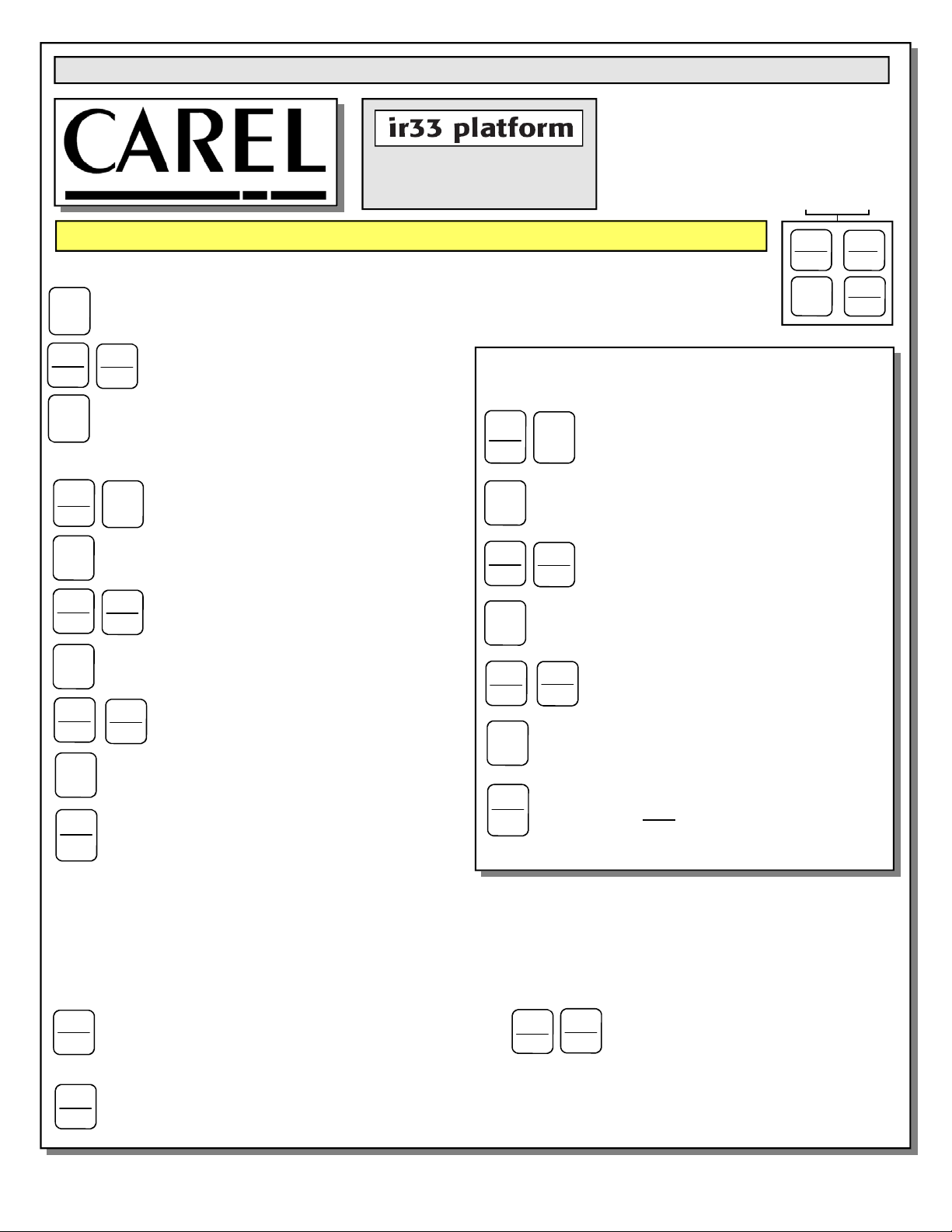
To Modify The Setpoint
Press and hold the “SET” key for at least 1 second.
Set
Prg
mute
Set
▲
aux
def
▼
▲
aux
3. Quickly press and release the “SET” key again.
Set
To Modify Defrost, Differential or Other Parameters
Prg
mute
Set
▲
aux
Set
▲
aux
Set
Prg
mute
Warning! Save Your Parameter Settings!
1. To store the new parameter values, PRESS and HOLD the “Prg” key for at least 5 seconds.
2. All modifications made to parameters will be lost if you do NOT press a button within 60 seconds. Should
this “timeout” occur, normal operational settings (prior to modifications being made) will resume.
3. If the instrument is switched off before pressing the “Prg” key, all modifications to parameters will be lost.
def
▼
▲
aux
2. Use arrow keys ▲ ▼ on temperature
def
controller to increase (or decrease) the
▼
setpoint.
1. Press & hold “Prg” & “SET” keys together
Set
for five (5) seconds; display will flash “0”,
representing password prompt.
2. Confirm by pressing “SET” key.
3. Press ▲ or ▼ to reach the
def
category to be modified.
▼
4. Press “SET” to modify this selected parameter.
6. Press the “SET” key to temporarily save the new
value and return to the display of the parameter.
7. Press & hold the “Prg” key for at least 5 seconds
to save changes. This action will also mute the
audible alarm (buzzer) & deactivate the alarm relay.
To Activate Manual Defrost
Press and hold the “def” key for at least 5 seconds.
To Activate / Deactivate Auxiliary Output
Press and hold the “aux” key for 1 second.
5. Increase or decrease the value using
def
the ▲ or ▼ button respectively.
▼
How To Change Reading From
Prg
mute
Set
2. Confirm by pressing “SET” key.
▲
aux
4. Press “SET” to modify this selected parameter.
Set
▲
aux
Set
1. Press and hold “Prg” and “SET” keys
together for at least 5 seconds; display will
Set
show “0”, representing password prompt.
3. Press ▲ or ▼ until reaching the
def
parameter “/ 5”.
▼
5. Press ▲ or ▼ to change value to desired
def
setting: “0” for Celsius (°C) or “1” for
▼
Fahrenheit (°F).
6. Press “SET” key to temporarily save the new
value and return to the display of the parameter.
Fahrenheit (°F) To Celsius (°C)
7. Press & hold “Prg” key for at least 5 seconds to
Prg
save changes.
mute
convert to new scale. No conversion is required.
Prg
mute
▲
aux
key for at least 1 second.
Note! All values will automatically
To Reset Any Alarms With Manual
Reset
Press and hold the “Prg” and “aux”
Structural Concepts Corp., 888 E. Porter Rd · Muskegon, MI 49441
Ph: 231.798.8888 / Fax: 231-798-0393 / www.structuralconcepts.com
30
I:\Oper Manuals - PUB\Templates\Carel Controller\Carel Controller IR33.pub
This data derived from Carel Material: ir33 +030220441 - rel. 2.0 - 01.05.2006
Page 31
Read And Save These Instructions - Page 2 of 3
Integrated Electronic
Microprocessor Controller
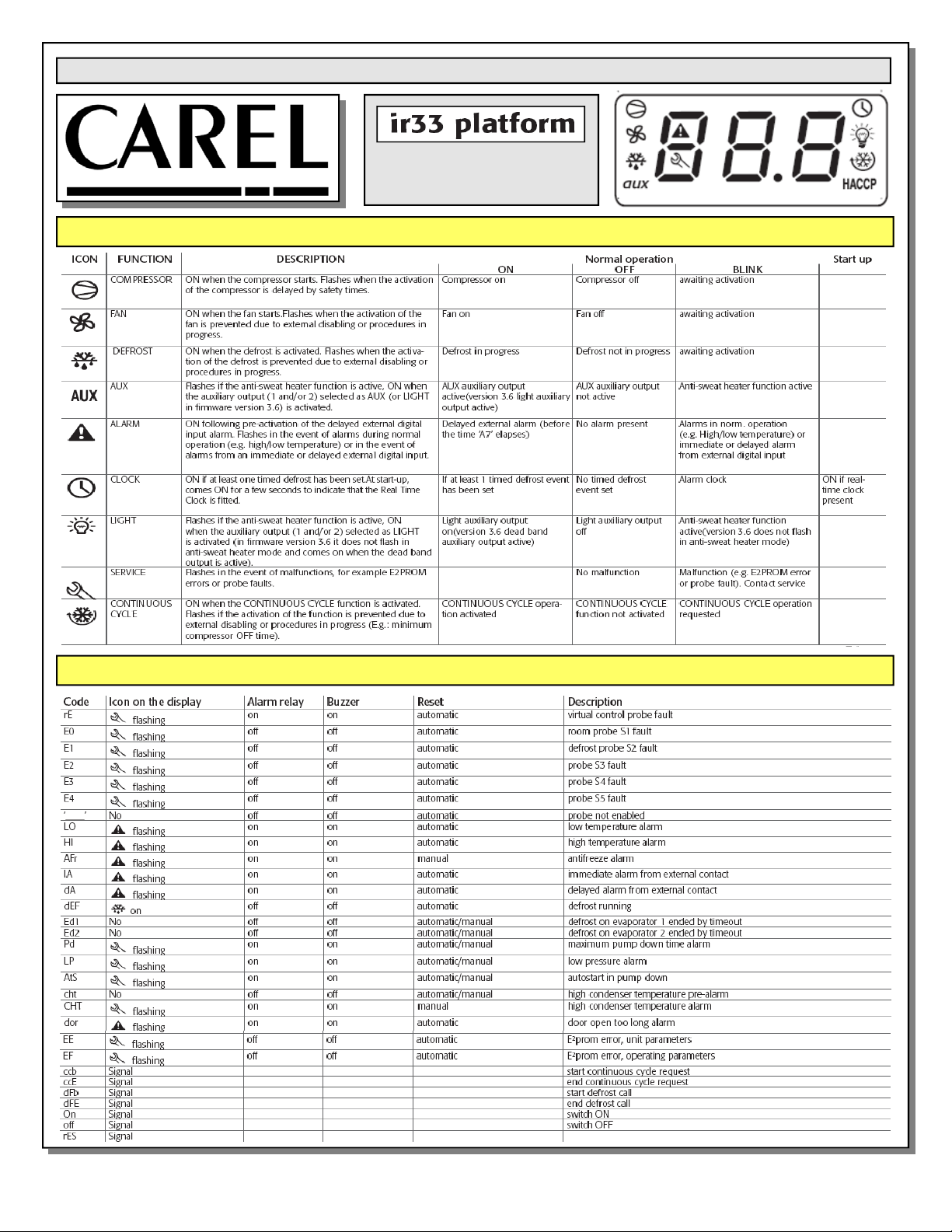
User Interface - Display
Summary Table of Alarm and Signals: Display, Buzzer and Relay
reset alarms w/manual reset / reset HACCP alarms / reset temp. monitoring
Structural Concepts Corp., 888 E. Porter Rd · Muskegon, MI 49441
Ph: 231.798.8888 / Fax: 231-798-0393 / www.structuralconcepts.com
31
I:\Oper Manuals - PUB\Templates\Carel Controller\Carel Controller IR33.pub
This data derived from Carel Material: ir33 +030220441 - rel. 2.0 - 01.05.2006
Page 32
Read And Save These Instructions - Page 3 of 3
Integrated Electronic
Microprocessor Controller
Summary Table of Operating Parameters
CODE PARAMETER UOM* TYPE MINIMUM MAXIMUM DEFAULT
/5
Select Celcius (°C) or Fahrenheit (°F)
flag C 0 1
/c1 Calibration of probe 1 °C/°F C -20 20
/c2 Calibration of probe 2 °C/°F C -20 20
St Temperature set point °C/°F F r2 r1
rd Control delta °C/°F F 20 0.1
dl Interval between defrosts hours F 0 250
dt1 End defrost temperature, evaporator °C/°F F -50 200
dP1 Maximum defrost duration, evaporator min F 1 250
d6 Display on hold during defrost - C 0 2
For Case
Specific
Defaults
See Serial
Label
Located
Near
Electrical
Access
On Your
Case.
For
Additional
Technical
Information
Call
Structural
Concepts
Technical
Service
Dept. at
1(800)
433.9489
dd Dripping time after defrost min F 0 15
d/1 Display of defrost probe 1 °C/°F F - -
* Unit Of Measure
Structural Concepts Corp., 888 E. Porter Rd · Muskegon, MI 49441
Ph: 231.798.8888 / Fax: 231-798-0393 / www.structuralconcepts.com
32
I:\Oper Manuals - PUB\Templates\Carel Controller\Carel Controller IR33.pub
This data derived from Carel Material: ir33 +030220441 - rel. 2.0 - 01.05.2006
Page 33
SCC TECHNICAL SERVICE CONTACT INFORMATION & WARRANTY INFORMATION
STRUCTURAL CONCEPTS CORPORATION TECHNICAL SERVICE: Call 1.800.433.9490 or For Your Master
Service Agent See WWW.STRUCTURALCONCEPTS.COM/Contact/Master_Service_Agents.asp
LIMITED WARRANTY
All sales by Structural Concepts Corporation (SCC) are subject to the following limited warranty. “Goods” refers to the product or products being sold by SCC.
Warranty Scope: Warranty is for equipment sold in the United States, Canada, Mexico and Puerto Rico. Equipment sold elsewhere may carry modified warranty.
Warranty; Remedies; Limitations: The limit of liability of SCC toward the exchange cost of the original compressor motor (and/or any other components) is one year parts and
labor. If any Goods are found to be of faulty material or workmanship within one year of the original F.O.B. unit shipment, SCC will, at its option (after inspection by an authorized
representative), replace or pay the reasonable cost of replacement of the faulty Goods. If warranty claim is not made within this one year time period, SCC is not bound to warrant
Goods. A motor-compressor (and/or any other components) replaced during the warranty shall not exceed manufacturer's current established wholesaler’s exchange price. If
replacement motor-compressor (and/or other components) is available via storage facility, parts truck, etc., SCC mandates that readily accessible replacement components be
used toward repair of Goods; in such instances, SCC will replace such equipment (at its own expense) after confirmation of its use/placement on defective unit. SCC shall not be
charged an additional fee, up-charge or expense for such replacement Goods. If SCC is unable to repair or replace the defective Goods, SCC shall issue a credit to the
Purchaser for full or partial purchase price, as SCC shall determine. The replacement or payment in the manner described above shall be the sole and exclusive remedy to
Purchaser for a breach of this warranty. If any Goods are defective or fail to conform to this warranty, SCC will furnish instructions for their disposition. No Goods shall be returned
to SCC without its prior consent.
SCC’s liability for any defect in the Goods shall not exceed the purchase price of the Goods. SCC SHALL HAVE NO LIABILITY TO PURCHASE FOR CONSEQUENTIAL
DAMAGES OF ANY KIND WHATSOEVER, INCLUDING, BUT NOT LIMITED TO, PERSONAL INJURY, PROPERTY DAMAGE, LOST PROFITS, OR OTHER ECONOMIC
INJURY DUE TO ANY DEFECT IN THE GOODS OR ANY BREACH OF SCC, SCC SHALL NOT BE LIABLE TO THE PURCHASER IN TORT FOR ANY NEGLIGENT DESIGN
OR MANUFACTURE OF THE GOODS, OR FOR THE OMISSION OF ANY WARNING THEREFROM.
SCC shall have no obligation or liability under this warranty for claims arising from any other party’s (including Purchaser’s) negligence or misuse of the Goods or environmental
conditions. This warranty does not apply to any claim or damage arising for or cause by improper storage, handling, installation, maintenance, or from fire, flood, accidents,
structural defects, building settlement or movement, acts of God, or other causes beyond SCC’s control.
Except as expressly stated herein, SCC makes no warranty, express, implied, statutory or otherwise as to any parts or goods not manufactured by SCC. SCC shall warrant such
parts or Goods only (I) against such defects, (II) for such periods of time, and (III) with such remedies, as are expressly warranted by the manufacturer of such parts of Goods.
Notwithstanding the foregoing, any warranty with respect to such parts of Goods and any remedies available as a result of a breach thereof shall be subject to all of the
procedures, limitations, and exclusions set forth herein.
THE WARRANTIES HEREIN ARE IN LIEU OF ALL WARRANTIES, EXPRESS, IMPLIED, STATUTORY, OR OTHERWISE. IN PARTICULAR, SCC MAKES NO WARRANTY
OF MERCHANTABILITY OR FITNESS FOR A PARTICULAR PURPOSE.
No representative, agent or dealer of SCC has authority to modify, expand, or extend this Warranty, to waive any of the limitations or exclusions, or to make any different or
additional warranties with respect to Goods.
Period of Limitations: No claim, suit or other proceeding may be brought by Purchaser for any breach of the foregoing warranty or this Agreement by SCC or in any way arising
out of this Agreement or relating to the Goods after one year from the date of the breach. In the interpretation of this limitation on action for a breach by SCC, it is expressly
agreed that there are no warranties of future performance of the goods that would extend that period of limitation herein contained for bringing an action.
Indemnifications: Purchaser agrees to indemnify, hold harmless, and defend SCC if so requested, from any and all liabilities, as defined herein, suffered, or incurred by SCC as
a result of, or in connection with, any act, omission, or use of the Goods by Purchaser, its employees or customers, or any breach of this Agreement by Purchaser. Liabilities
shall include all costs, claims, damages, judgments, and expenses (including reasonable attorney fees and costs).
Remedies of SCC: SCC’s rights and remedies shall be cumulative and may be exercised from time to time. In a proceeding or action relating to the breach of this Agreement by
Purchaser, Purchaser shall reimburse SCC for reasonable costs and attorney’s fees incurred by SCC. No waiver by SCC of any breach of Purchaser shall be effective unless in
writing nor operate as a waiver of any other breach of the same term thereafter. SCC shall not lose any right because it has not exercised it in the past.
Applicable Law. This Agreement is made in Michigan; it is governed by and interpreted according to Michigan law. Any lawsuit arising out of this Agreement or the Goods may be
handled by a federal or state court whose district includes Muskegon County, Michigan, and Purchaser consents that such court shall have personal jurisdiction over Purchaser.
LED Lighting Components Within Lighting System: Retail: 5-year LED warranty from date of shipment. Foodservice: 2-year LED warranty from date of shipment. After one
year, warranty does not include labor or other costs incurred for diagnosing, repairing, removing, installing, shipping, servicing, or handling of either defective part or replacement
parts. The remedy of repair or provision of a replacement part without charge shall be the exclusive remedy for any warranty claim. The replacement LED and/or power supply
assumes the unused portion of warranty remaining on unit(s). A 90-day warranty will apply for any LED sold as a service part. Warranty claim must include serial and model
number of unit as well as date code on defective LED lighting component(s). Manufacturer may request return of defective part(s) at customer’s expense to initiate claim.
Miscellaneous: If any provision of this Agreement is found to be invalid or unenforceable under any law, the provision shall be ineffective to that extent and for the duration of
the illegality, but the remaining provisions shall be unaffected. Purchaser shall not assign any of its rights nor delegate any of this obligations under this Agreement without prior
written of SCC. This Agreement shall be binding upon and inure to the benefit of SCC and Purchaser and each of their legal representatives, successors and assigns.
SCC warrants its products to be free of defects in materials and workmanship under normal use and service for a period of one (1) year from the date of delivery.
This warranty is extended only to the original purchaser for use of the Goods. It does not cover normal wear parts such as plastic tongs, tong holders, tong cables, bag holders,
or acrylic dividers.
General Conditions: All service labor and/or parts charges are subject to approval by SCC. Contact the Customer Service Department in writing or call 231-798-8888.
All claims must contain the following information: (1) model & serial code number of equipment; (2) the date and place of installation; (3) the name and address of the agency
which performed the installation; (4) the date of the equipment failure; and (5) a complete description of the equipment failure and all circumstances relating to that failure.
Once the claim has been determined to be a true warranty claim by SCC’s Customer Service Department, the following procedure will be taken: (1) replacement parts will be sent
at no charge from SCC on a freight prepaid basis; (2) reimbursement for service labor will be paid if the following conditions have been met - (a) prior approval of service agency
was awarded from the Customer Service Department; and (b) an itemized statement of all labor charges incurred is received by the Customer Service Department. The cost of
the service labor reimbursement will be based on straight time rates and reasonable time for the repair of the defect.
If problems occur with any compressor, notify SCC’s Customer Service Department immediately. Any attempt to repair or alter the unit without prior consent from the Customer
Service Department will render any warranty claim null and void. This warranty and protection plan does not apply to any condensing unit or any part thereof which has been
subject to accident, negligence, misuse, or abuse, or which has not been operated in accordance with the manufacturer’s recommendations or if the serial number of the unit has
been altered, defaced, or removed.
One Year Limit of Liability: After SCC's one-year parts and labor warranty on the original F.O.B. unit has expired, SCC is not liable for either the equipment or labor costs of
repairing or replacing the motor compressor, nor any other components that were included in the original F.O.B. unit.
33
SCC Warranty Revision G Date: 6.1.2016
 Loading...