

Page 1

READ AND SAVE THESE INSTRUCTIONS
G-SERIES
G-SERIES GMS4H,
GMS6H & GMS8H
HEATED
SERVICE CASES
Model GMS6H
Shown at Right
INSTALLATION
AND OPERATING
MANUAL
PN 20-00367
888 E. Porter Road · Muskegon, MI 49441 Phone: 231.798.8888 Fax: 231.798.4960 www.structuralconcepts.com
I:\Oper Manuals - PUB\G-Series\GMS4H_GMS6H_GMS8H_20-00367.pub
Model GMS8H
Shown at Left
Model GMS4H……...….51”L* x 43 3/8”D^ x 51 51 5/8~
Model GMS6H………....75 3/8”L* x 43 3/8”D^ x 51 51 5/8~
Model GMS8H……...…99 3/4”L* x 43 3/8”D^ x 51 51 5/8~
*Includes End Panels (Deduct 2 1/4” If No End Panels)
~From Floor to Top of Unit ^50 3/8” With Rear Ledge Raised
Rev F Date: 10.22.2013
Page 2

TABLE OF CONTENTS
OVERVIEW / CONDITION TYPE / TEMP / COMPLIANCE / WARNINGS / PRECAUTIONS /
WIRING ……………………………………………………………....………………………………….
INSTALLATION INSTRUCTIONS ...………………..……………………………………...………………….
ELECTRICAL ACCESS AND CONNECTIONS ……………………………………………………………..
PHASE SELECTOR SWITCH (SINGLE-PHASE VS. THREE-PHASE) / PAN PLACEMENT ………….
START-UP / LIGHTING / CASE TEMPERATURES / PRODUCT HEATING / SCC TEMPERATURE
CONTROLLERS ……………………………………………………………………………………….
OVERHEAD CERAMIC HEATERS …………………………………………………………………………..
LIGHT FIXTURES ………………………………………………………… …………………………………...
FRONT GLASS / REAR DOORS / OPTIONAL REAR LEDGE …..………………..……………………...
OPTIONAL SCALE STAND ……………………………………………… ……………………………………
MAINTENANCE FUNDAMENTALS .………………………..…………………..…………………………….
SERIAL LABEL LOCATION & INFORMATION LISTED / TECH INFO & SERVICE …………………….
CLEANING SCHEDULE …………………………………………………………………..…………………...
TROUBLESHOOTING ..………………………………………………………………………………...……...
TECHNICAL SERVICE CONTACT INFORMATION & WARRANTY INFORMATION ….….…………...
3-4
5
6
7
8
9
10
11
12
13-14
15
16
17
18
2
Page 3

OVERVIEW / TYPE / TEMP / COMPLIANCE / WARNINGS / PRECAUTIONS / WIRING - PAGE 1 of 2
OVERVIEW
This merchandiser is designed for dry heating operations
throughout the product area. The heat is generated from
electric rod well warmers as well as ceramic heaters and
overhead ceramic metal halide lamps.
This merchandiser is designed for display of
perishable, unpackaged heated products.
This merchandiser IS NOT designed to heat products
up; product must be pre-heated PRIOR to its display.
Cases should be installed and operated according to
this operating manual’s instructions to ensure proper
performance.
Improper use will void warranty.
TYPE
This unit is designed for the display of products in ambient
store conditions where temperatures and humidity are
maintained within a specific range.
Ambient conditions are to be at 55% max. humidity
and maximum temperatures of 75 °F (24 °C).
INTEGRATED AVERAGE PRODUCT TEMPERATURE
The Structural Concepts® G-Series Service Deli
Merchandisers are designed to merchandise product
at an integrated average product temperature of
150 °Fahrenheit / 66 °Celsius.
COMPLIANCE
Performance issues when in violation of applicable
NEC, federal, state and local electrical and plumbing
codes are not covered by warranty.
See below compliance guideline.
WARNINGS
This page contains important warnings to prevent
injury or death.
Please read carefully!
PRECAUTIONS and WIRING DIAGRAMS
See next page for PRECAUTIONS and WIRING
DIAGRAM information.
WARNING
ELECTRICAL
HAZARD
WARNING
HOT
SURFACE
WARNING
HOT
SURFACE
COMPLIANCE
This equipment MUST be installed in compliance with
all applicable NEC, federal, state and local
electrical and plumbing codes.
WARNING
Risk of electric shock. Disconnect power before servicing unit.
CAUTION! More than one source of electrical supply is
employed with units that have separate circuits.
Disconnect ALL ELECTRICAL SOURCES before servicing.
WARNING
Pans and Wells Are Hot!
Disconnect and allow to cool
before cleaning or removing from case.
WARNING
Ceramic Heaters and Ceramic Metal Halide Lamps Are Hot!
Turn Off or Disconnect and Allow to Cool
Before Servicing or Replacing.
3
Page 4

OVERVIEW / TYPE / TEMP / COMPLIANCE / WARNINGS / PRECAUTIONS / WIRING - PAGE 2 of 2
PRECAUTIONS
Following are important precautions to prevent
damage to unit or merchandise.
Please read carefully!
See previous page for specifics on OVERVIEW,
CONDITION TYPE, COMPLIANCE and WARNINGS.
WIRING DIAGRAM
Each case has its own wiring diagram folded and in
its own packet.
Wiring diagram placement may vary; it may be
placed near ballast box, field wiring box, raceway
cover, or other related location.
CAUTION
CAUTION! LAMP REPLACEMENT GUIDELINES
Allow to cool before accessing lamps.
Lamps are NOT manufactured to resist breakage.
Replace with similarly manufactured lamps of same wattage.
See Maintenance Fundamentals section in this manual for specifics.
CAUTION! GFCI BREAKER USE REQUIREMENT
If N.E.C. (National Electric Code) or your local code
requires GFCI (Ground Fault Circuit Interrupter) protection,
you MUST use a GFCI breaker in lieu of a GFCI receptacle.
WIRING DIAGRAM FORMAT & LOCATION
Each case has its own wiring diagram folded & in its own packet.
Wiring diagram placement may vary; it may be placed near ballast
box, field wiring box, raceway cover, or other related location.
4
Page 5

INSTALLATION INSTRUCTIONS
Installation
: Units shown may not depict an exact representation of your particular unit being installed.
Note
Slide
Skid
Out
1. Remove Unit From Skid
Caution: case must always remain supported or
center of gravity will allow case to fall. Slide unit to
rear of skid and tip backward off skid.
3. Bolting Adjoined Units
View shown is after removal of end panel.
Approximate bolt adjoinment locations are illustrated
below (balloons 1-5).
Factory-determined adjoinment locations will have
bolts pre-inserted with nuts/washers provided.
Illustration below may not exactly reflect your case.
Support
required
to prevent
tipping.
2. Case Aligning, Adjusting and Sealing
For service glass to align properly, case must be
level and plumb.
Shims will be provided with all cases that have
frame support rails.
Note: After case is in position, it must be
sealed to floor to prevent entry or leakage of
liquid or moisture.
Caution! These units MUST BE sealed to the
floor to maintain conformance to equipment
mounting standards.
Align multiple units.
4. Electrical Connections: Access and Field
Wiring
See next page.
Frame
Support
Rails
1
2
3
4
5
5
Page 6
ELECTRICAL ACCESS AND CONNECTIONS
Installation Instructions, Continued
: Units shown may not depict an exact representation of your particular unit being installed.
Note
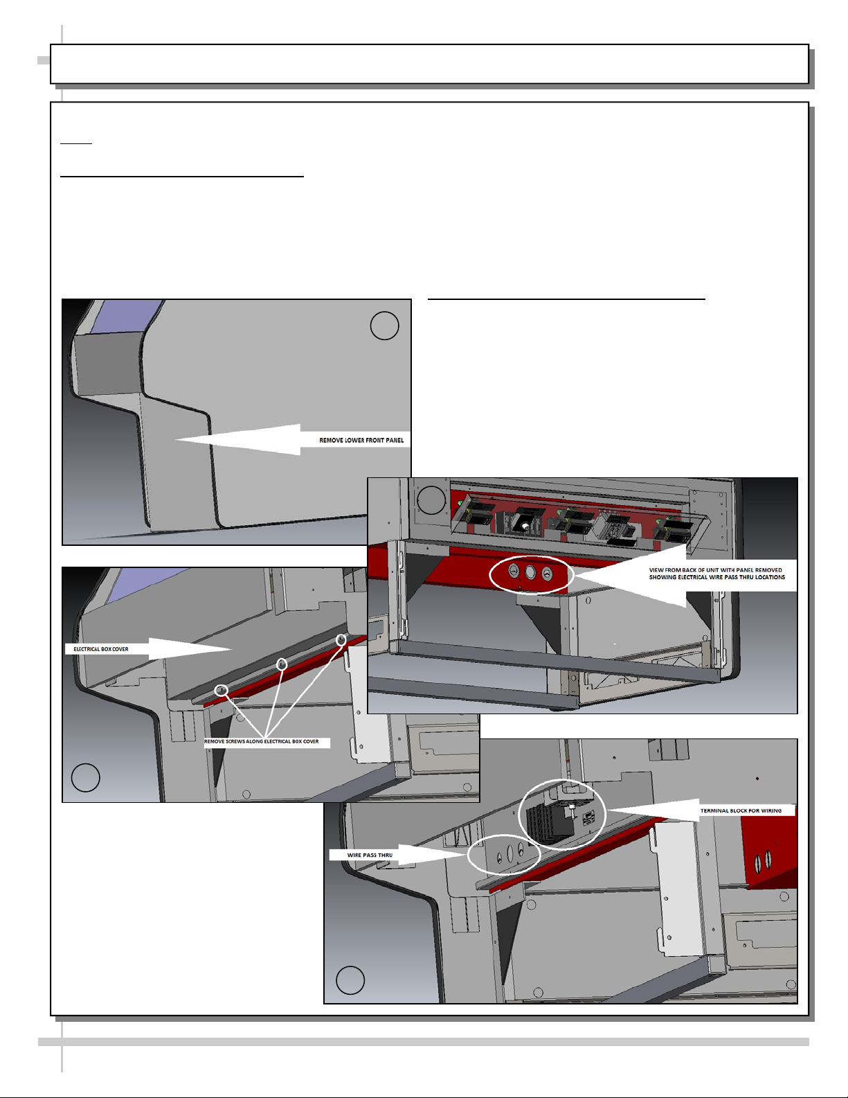
1. Electrical Connections: Access
A. Remove lower front panel. No screw removal is
required. Simply lift up and off.
B. View from back of case with panel removed
(showing electrical wire pass-through locations).
A
C. Remove screws along lower area of electrical box
cover.
D. Electrical box cover may now be removed.
Pass-through for field wiring is now accessible.
Also, you may now access terminal block, phase
selector switch and other components in raceway.
2. Electrical Connections: Field Wiring
Field wiring hook-up / electrical access location is
shown in the view below.
Unit may be wired single or three-phase.
See next page for phase selector instructions.
See wiring diagram for additional information.
B
C
D
6
Page 7

PHASE SELECTOR SWITCH (SINGLE-PHASE VS. THREE-PHASE) / PAN PLACEMENT IN WELLS
1. Phase Selector Switch
Remove front panel to access.
Phase selector switch MUST match your
field wiring (either single-phase or threephase).
Authorized electrician MUST make
determination.
See illustrations below.
2. Pan Placement
Case is designed to hold several pan sizes.
Either 1/3rd wells or full wells may be placed
at either front or rear of case.
See illustrations at mid-right for 1/3rd size
and full-size pans in heated wells.
Well
Areas
For
Holding
Pans
7
Note: Illustrations May Not
Exactly Reflect Every
Feature or Option of
Your Particular Case
Pan (1/3rd
Size)
Pan (Full
Size)
Page 8

START-UP / LIGHTING / CASE TEMP. / PRODUCT HEATING / SCC TEMP ERATURE CONTROLLERS
1. Merchandiser Start-Up
Case must be field wired.
When power is supplied, throw main power switch
at case rear-right and case will power-up.
2. Lighting
Overhead light switch is at case rear, right
side (see illustration below).
3. Case Temperature
Well temperature is dependent upon both the
waterless well temperature and the overhead
ceramic heater temperatures.
Preheat to 170 °F on case temperature dial
(photo shown below-left) before placing food
into case.
Caution Temperature reflects internal
case temperature ONLY (not product
temperature). Use a food probe to
determine ACTUAL product temperature!
4. Product Heating Guidelines/SCC Temp. Controllers
Well and overhead ceramic heaters are controlled by
Structural Concepts Temperature Controllers.
These controllers are located on rear wireway cover
(as shown in illustration below-right).
For proper temperature settings, carefully follow these
procedures:
Press Preheat as soon as main power switch is
turned on. LED indicator will come on. It will shut
off on its own.
Set both Well and Overhead at “5” to begin.
To increase temperature, press the “UP” key .
To decrease temperature, press the “DOWN” key .
If controller is set to “0”, relays will de-energize.
Setting ”1” is minimum heat.
Setting “9” is maximum heat.
The HEAT LED indicates that the relay is
energized and Heater is “On”.
After unit is adjusted, the control will automatically
save the user setting approximately 5 seconds
after user stops adjusting the setting.
Note: During peak usage, slightly higher settings
may be required to maintain recommended
product heating temperatures.
Case
Temperature Dial
Structural Concepts
Temperature Controller at
Rear Panel (Typical)
y
e
K
”
P
U
“
(
W
O
D
“
)
l
a
c
i
p
y
T
y
e
K
”
N
)
l
a
c
i
p
y
T
(
8
Page 9

OVERHEAD CERAMIC HEATERS
Overhead Ceramic Heater Guidelines and Settings
Each overhead ceramic heater operates independently of each other.
Previous page provides step-by-step procedures for attaining proper temperature settings.
Below Illustration May Not Exactly Reflect Every
Feature or Option of Your Particular Case
Overhead
Ceramic
Heaters
9
Page 10

LIGHT FIXTURES
Light Fixtures
Warning! Disconnect power before providing
maintenance & service to unit.
Warning! Lamps are NOT manufactured to resist
breakage. Replace with same wattage ceramic
metal halide lamps (similarly manufactured). If
uncertain of wattage, refer to label near rear
sliding doors for specifics.
Warning! As ceramic heaters may also heat up
light fixture area, make certain that entire area
has been allowed to cool before touching light
fixtures.
Below Illustration May Not Exactly Reflect Every
Feature or Option of Your Particular Case
As ceramic metal halide lamps may take up to 15
minutes to gain full illumination
, turn on lamps
BEFORE loading product into case. This will
allow proper time for proper illumination.
Find overhead light switch location on
START-UP / LIGHTING / CASE TEMP. /
PRODUCT HEATING / SCC TEMPERATURE
CONTROLLERS section in manual.
Light switch turns on lamps to entire overhead
section of case.
To access light fixtures, remove fasteners.
Then, slide overhead lamp housing toward case
center (allowing screw to housing slot) and lower
housing down from case.
Replace light fixtures as necessary.
Thumb Screw
For Lamp
Access (Typical)
Ceramic Metal Halide Lamps
From Partially Disassembled
Case (Typical)
10
Page 11

FRONT GLASS / REAR DOORS / OPTIONAL REAR LEDGE
1. Raise the Curved Glass
To raise the front glass, secure the lift handle
extrusion on the bottom edge of the door and
lift up. Gas cylinders hold the glass open for
hands-free access to the interior of the case.
Caution: Gently return curved glass to
original position.
See illustration at right.
2. Removing the Rear Doors
Note: Doors are not interchangeable. There is an
inner and outer door. The outer must be removed
first and replaced last.
The outer door, is the right hand door (from
the service side or rear of the case). It can be
identified by a stop located at the lower right
hand corner to the inside of the case.
Move the doors toward the center of the case.
Individually lift each door up toward the top of
the case and pivot the bottom of the door out.
Reverse to install.
See illustration at right.
Caution: Gently set doors down to avoid
marring, scraping, scratching or breakage.
3. Rear Ledge Removal Steps
-1- -2- -3- -4-
Rear Ledge is connected to Shelf Track.
Illustrations at right reflect step-by-step
removal method (as enumerated below).
1. Hinged Support Bracket is shown in
its standard upright position.
2 & 3. While upright, Rear Ledge must be
Hinged
Support
Bracket
slid away from case and then rotated downward
to vertical position.
3 & 4. From the shelf’s lowered position, lift from
bottom edge upward to disengage shelf track
(and attached Rear Ledge) from bracket.
————— Rear Ledge Removal Steps —————
Note: For clarity, only Shelf Track is shown being
removed. Rear Ledge is attached to Shelf Track.
View of Curved
Glass being
raised
Shelf
Track
View of Rear
Doors being
lifted up,
pivoted out and
away from
case.
Rear
Ledge
Shelf
Track
Hinged
Support
Bracket
11
Page 12

OPTIONAL SCALE STAND
Optional Scale Stand
Scale stand is provided with receptacle
which is to be wired separately.
Depending upon order, scale stand
may be at either left or right of case.
View of Typical Case With
Scale Stand and Receptacle
Scale
Stand
Scale Stand
Receptacle
12
View of Case
Without Scale
Stand and
Receptacle
Page 13

MAINTENANCE FUNDAMENTALS
Warning! Disconnect power before providing
maintenance or service to unit.
Assembly, disassembly and servicing to be
accomplished by licensed electrical contractor.
Follow these instructions for proper servicing
of electrical components.
Remove the screws along top of rear electrical
dashboard (see arrows in below illustration
pointing to general locations).
Dashboard (with light switch, main power switch,
temperature controllers, terminal blocks, and
ballasts) will flip downward.
Electrical components may now be accessed for
service or maintenance.
Return to previous state by flipping back up and
replacing screws.
Power may now be restored to unit.
Flip-Down
Panel
Model GMS8H With
Rear Panel Intact
Ballasts
Flip-Down
Terminal
Block
Panel
Terminal
Block
Flip-Down
Panel
Overhead
Light
Switch
Main
Power
Switch
Wireway
Route
Model GMS8H After Rear Panel Removed
(For Illustrative Purposes Only)
13
Page 14

MAINTENANCE FUNDAMENTALS, CONTINUED
Removing Pan and Dividers (for Cleaning)
Note: Make certain that unit has been turned off and
allowed to cool before accessing.
1. Remove 1/3rd-Size and Full Size Pans.
2. Remove pan dividers.
Below Illustration May Not Exactly Reflect Every
Feature or Option of Your Particular Case
Pan
(Full Size)
(1/3rd Size)
3. Perform cleaning service on pan warmer shield.
4. Replace pan dividers and pans in reverse order they
were removed.
: See cleaning schedule for specifics on
Note
method and frequency of cleaning.
Pan
Pan
Dividers
1. Remove 1/3rd-Size, Full
Size and Drip Pans
3. Perform cleaning
2. Remove pan dividers
service on pan
warmer shield
4. Replace pan
dividers and pans in
reverse order they
were removed
14
Page 15

SERIAL LABEL LOCATION & INFORMATION LISTED / TECH INFO & SERVICE
Serial Label Location & Information Listed / Technical Information & Service
Serial labels are located near the electrical access on your case.
Serial labels contain electrical, temperature & refrigeration information, as well as regulatory
standards to which the case conforms.
For additional technical information and service, see the TECHNICAL SERVICE page in this
manual for instructions on contacting Structural Concepts’ Technical Service Department.
See images below for samples of both refrigerated and non-refrigerated serial labels.
S
A
M
P
L
E
O
N
L
Y
Y
L
N
O
E
L
P
M
A
S
----- Sample Serial Label For Refrigerated Case -----
Y
L
N
O
E
PL
M
SA
----- Sample Serial Label For Non-Refrigerated Case -----
15
Page 16

CLEANING SCHEDULE
Warnings:
1. DO NOT clean heated wells while hot. Flip Well Heater Switches to OFF position. Allow wells to
cool to room temperature before cleaning.
2. Lowering the front glass with items inside top cap can cause damage to case.
3. Lowering the front glass with fingers inside top cap can cause serious injury.
Cleaning Daily Weekly Task
Clean side glass, front curved glass and sliding rear doors
Clean Case Exterior X
(glass) with a household or commercial glass cleaner.
Stainless Steel Rear Work Surface:
Wash with a solution of hand dishwashing liquid detergent and
water; or a solution of baking soda and water. Rinse and
X
polish dry with paper towel or soft cloth.
Never use scouring powders or steel wool as they will scratch
stainless steel.
Brighten by polishing with a cloth dipped in vinegar or in
ammonia; sprinkle baking soda on sponge and rub gently;
rinse. Polish dry with paper towel.
Remove streaks or heat stains from stainless steel by rubbing
with club soda.
X
Clean Case Interior X
X
X
X
Flip-down rear ledge:
Use a clean cloth with a solution of hand dishwashing liquid
detergent and hot water. Rinse and wipe dry with paper towel
or clean cloth.
Clean inside surface of front curved glass and glass ends with a
household or commercial glass cleaner.
Remove pans (see full size and 1/3rd size pans illustrations in
MAINTENANCE FUNDAMENTALS section of this manual) and
submerse in with warm soap and water solution. Thoroughly dry
before returning to case.
Pan Warmer Shield (surface under removable pans).
Caution! Turn Well Heater Switches to OFF position.
Allow wells to cool to room temperature before cleaning.
Clean with mild soap and water solution and a soft cloth.
Remove rear doors and clean with a household or commercial
cleaner
16
Page 17

TROUBLESHOOTING
System is not operating
Warmers will not heat
Warmers slow to heat
Case lights not working
Check that the utility power is on.
Check that the MAIN Power Switch is on.
Check the circuit breaker box for tripped circuits.
Check that temperature controllers (at case rear) are at proper
settings.
Check that temperature controllers (at case rear) are at proper
settings.
Check that Overhead Light Switch is turned on.
Check lamps for proper installation and connection.
Caution! Ceramic metal halide lamps are extremely hot! Use
caution when accessing!
Unscrew thumbscrew to remove cover. Caution! Securely hold
lamp cover when removing thumb screw! Both lamp cover and
glass will fall downward when thumbscrew is removed!
Check for burned out bulbs.
Thumb Screw For Lamp
Access (Typical)
Ceramic Metal Halide
Lamps (Typical)
Note: Model Shown Partially
Disassembled For
Illustrative Purposes Only.
Thumb Screw For Lamp
Access (Typical)
17
Page 18

SCC TECHNICAL SERVICE CONTACT INFORMATION & WARRANTY INFORMATION
STRUCTURAL CONCEPTS CORPORATION TECHNICAL SERVICE
PHONE NUMBER: 1.800.433.9489 or For Your Master Service Agent See
WWW.STRUCTURALCONCEPTS.COM/Contact/Master_Service_Agents.asp
LIMITED WARRANTY
All sales by Structural Concepts Corporation (SCC) are subject to the following limited warranty. “Goods” refers to the product or products being sold by SCC.
Warranty Scope: Warranty is for equipment sold in the United States, Canada, Mexico and Puerto Rico. Equipment sold elsewhere may carry modified warranty.
Warranty; Remedies; Limitations. SCC warrants that if any Goods are found by an authorized representative of SCC not to be of good material or workmanship within one
year of the date of shipments SCC will, at its option after inspection by an authorized representative, replace any defective Good or pay the reasonable cost of replacement for
any such defective Goods, provided that written notice of the defect is given to SCC within 30 days of the appearance of such defect. If notice is not given within such period, any
claim for breach of warranty shall be conclusively deemed to have been waived and SCC shall not be liable under this warranty. If SCC is unable to repair or replace the defective
Goods, SCC shall issue a credit to the Purchaser for all or part of the purchase price, as SCC shall determine. The replacement or payment in the manner described above shall
be the sole and exclusive remedy of Purchaser for a breach of this warranty. If any Goods are defective or fail to conform to this warranty, SCC will furnish instructions for their
disposition. No Goods shall be returned to SCC without its prior consent.
SCC’s liability for any defect in the Goods shall not exceed the purchase price of the Goods. SCC SHALL HAVE NO LIABILITY TO PURCHASE FOR CONSEQUENTIAL
DAMAGES OF ANY KIND WHATSOEVER, INCLUDING, BUT NOT LIMITED TO, PERSONAL INJURY, PROPERTY DAMAGE, LOST PROFITS, OR OTHER ECONOMIC
INJURY DUE TO ANY DEFECT IN THE GOODS OR ANY BREACH OF SCC, SCC SHALL NOT BE LIABLE TO THE PURCHASER IN TORT FOR ANY NEGLIGENT DESIGN
OR MANUFACTURE OF THE GOODS, OR FOR THE OMISSION OF ANY WARNING THEREFROM.
SCC shall have no obligation or liability under this warranty for claims arising from any other party’s (including Purchaser’s) negligence or misuse of the Goods or environmental
conditions. This warranty does not apply to any claim or damage arising for or cause by improper storage, handling, installation, maintenance, or from fire, flood, accidents,
structural defects, building settlement or movement, acts of God, or other causes beyond SCC’s control.
Except as expressly stated herein, SCC makes no warranty, express, implied, statutory or otherwise as to any parts or goods not manufactured by SCC. SCC shall warrant such
parts or Goods only (I) against such defects, (II) for such periods of time, and (III) with such remedies, as are expressly warranted by the manufacturer of such parts of Goods.
Notwithstanding the foregoing, any warranty with respect to such parts of Goods and any remedies available as a result of a breach thereof shall be subject to all of the
procedures, limitations, and exclusions set forth herein.
THE WARRANTIES HEREIN ARE IN LIEU OF ALL WARRANTIES, EXPRESS, IMPLIED, STATUTORY, OR OTHERWISE. IN PARTICULAR, SCC MAKES NO WARRANTY
OF MERCHANTABILITY OR FITNESS FOR A PARTICULAR PURPOSE.
No representative, agent or dealer of SCC has authority to modify, expand, or extend this Warranty, to waive any of the limitations or exclusions, or to make any different or
additional warranties with respect to Goods.
Period of Limitations. No claim, suit or other proceeding may be brought by Purchaser for any breach of the foregoing warranty or this Agreement by SCC or in any way arising
out of this Agreement or relating to the Goods after one year from the date of the breach. In the interpretation of this limitation on action for a breach by SCC, it is expressly
agreed that there are no warranties of future performance of the goods that would extend that period of limitation herein contained for bringing an action.
Indemnifications. Purchaser agrees to indemnify, hold harmless, and defend SCC if so requested, from any and all liabilities, as defined herein, suffered, or incurred by SCC as
a result of, or in connection with, any act, omission, or use of the Goods by Purchaser, its employees or customers, or any breach of this Agreement by Purchaser. Liabilities
shall include all costs, claims, damages, judgments, and expenses (including reasonable attorney fees and costs).
Remedies of SCC. SCC’s rights and remedies shall be cumulative and may be exercised from time to time. In a proceeding or action relating to the breach of this Agreement by
Purchaser, Purchaser shall reimburse SCC for reasonable costs and attorney’s fees incurred by SCC. No waiver by SCC of any breach of Purchaser shall be effective unless in
writing nor operate as a waiver of any other breach of the same term thereafter. SCC shall not lose any right because it has not exercised it in the past.
Applicable Law. This Agreement is made in Michigan and shall be governed by and interpreted according to Michigan law. Any lawsuit arising out of this Agreement or the Goods
may be handled by a federal or state court whose district includes Muskegon County, Michigan, and Purchaser consents that such court shall have personal jurisdiction over
Purchaser.
Miscellaneous. If any provision of this Agreement is found to be invalid or unenforceable under any law, the provision shall be ineffective to that extent and for the duration of
the illegality, but the remaining provisions shall be unaffected. Purchaser shall not assign any of its rights nor delegate any of this obligations under this Agreement without prior
written of SCC. This Agreement shall be binding upon and inure to the benefit of SCC and Purchaser and each of their legal representatives, successors and assigns.
SCC warrants its products to be free of defects in materials and workmanship under normal use and service for a period of one (1) year from the date of delivery.
This warranty is extended only to the original purchaser for use of the Goods. It does not cover normal wear parts such as plastic tongs, tong holders, tong cables, bag holders,
or acrylic dividers.
General Conditions. All service labor and/or parts charges are subject to approval by SCC. Contact the Customer Service Department in writing or call 231-798-8888.
All claims must contain the following information: (1) model & serial code number of equipment; (2) the date and place of installation; (3) the name and address of the agency
which performed the installation; (4) the date of the equipment failure; and (5) a complete description of the equipment failure and all circumstances relating to that failure.
Once the claim has been determined to be a true warranty claim by SCC’s Customer Service Department, the following procedure will be taken: (1) replacement parts will be sent
at no charge from SCC on a freight prepaid basis; (2) reimbursement for service labor will be paid if the following conditions have been met - (a) prior approval of service agency
was awarded from the Customer Service Department; and (b) an itemized statement of all labor charges incurred is received by the Customer Service Department. The cost of
the service labor reimbursement will be based on straight time rates and reasonable time for the repair of the defect.
If problems occur with any compressor, notify SCC’s Customer Service Department immediately. Any attempt to repair or alter the unit without prior consent from the Customer
Service Department will render any warranty claim null and void. This warranty and protection plan does not apply to any condensing unit or any part thereof which has been
subject to accident, negligence, misuse, or abuse, or which has not been operated in accordance with the manufacturer’s recommendations or if the serial number of the unit has
been altered, defaced, or removed.
Limit of Liability. The limit of liability of SCC toward the exchange cost of the original condensing unit, F.O.B. SCC, Norton Shores, MI, of each motor-compressor assembly
replaced during the warranty shall not exceed manufacturer's current established wholesaler’s exchange price and in no case shall the labor of removing or replacing the
motor-compressor or parts thereof be the responsibility of SCC.
18
 Loading...