

Stropuva S7, S40, S7 BIO, S10, S10 BIO Technical Passport Installation And Maintenance Instructions
...
Solid fuel boiler for
central heating
STROPUVA
TECHNICAL PASSPORT
INSTALLATION AND MAINTNCE
INSTRUCTIONS

2
TECHNICAL PASSPORT INSTALLATION AND MAINTENANCE INSTRUCTIONS
Contents
1. TECHNICAL SPECIFICATIONS ....................................................................................... 3
1.1 MAIN TECHNICAL SPECIFICATIONS ........................................................................... 3
2. STRUCTURE OF BOILER ...............................................................................................5
2.1 DESCRIPTION OF BOILER STRUCTURE ....................................................................6
3 PARTS OF BOILER ........................................................................................................... 6
3.1 AIR INJECTION COLLECTOR (Figure 2) ......................................................................6
3.2 AIR DISTRIBUTOR WITH BURNING CHAMBER STABILIZER ...................................7
3.3 FIRE GRATE (Figure 4) ..................................................................................................8
3.5 DEFELCTORS (Figure 5) ............................................................................................... 8
3.5 FLUE RING (Figure 6) .................................................................................................... 9
3.6 SAFETY VALVE (1.5 BAR) ............................................................................................. 9
4. TRANSPORTING AND STORAGE ................................................................................10
5. INSTALLATION OF BOILER ..........................................................................................10
5.1 FIREFIGHTING REQUIREMENTS ..............................................................................10
5.2 FLUE REQUIREMENTS ..............................................................................................10
5.3 REQUIREMENTS FOR CONECTING TO HEATING SYSTEM ................................... 11
6. DIAGRAM OF HEATING SYSTEM ................................................................................12
6.1 DESCRIPTION OF DIAGRAM OPERATION (Figure 8) ...............................................13
6.2 diagram of connecting ,,Stropuva” boiler to other boiler, water heater and fl oor
heating ................................................................................................................................ 14
6.3 diagram of connecting ,,Stropuva” boiler to other boiler, water heater, radiators
and fl oor heating ................................................................................................................. 15
6.4 diagram of connecting ,,Stropuva” boiler to other boiler, water heater, radiators ......... 16
7. FIRING OF BOILER AND ADDING FUEL ...................................................................... 17
7.1 FUEL IN BOILER BURNS MOST EFFICIENTLY ......................................................... 17
7.2 RECOMMENDATIONS FOR FIRING OF UNIVERSAL BOILER ................................18
7.3 SETTINGS OF DRAFT REGULATOR (Figure 13) ....................................................... 19
7.4 ASSESMENT OF BOILER OPERATION .....................................................................19
8. REQUIREMENTS OF SAFETY EQUIPMENT ...............................................................20
7.5 CLEANING AND MAINTENANCE OF BOILER ...........................................................20
9. RISK ASSESSMENT ...................................................................................................... 21
9.1 DANGERS OF HEAT ...................................................................................................21
9.2 DANGERS OF PRESSURE ......................................................................................... 22
9.3 POSSIBLE POISONING ..............................................................................................22
9.4 REQUIRMENTS FOR CONECTING ELETRICAL PART ............................................. 22
10. ATTACHEMENTS ......................................................................................................... 22
10.1 ELECTRONICAL CONTROLLER ..............................................................................22
10.2 PELLET BURNER ...................................................................................................... 24
11. PACKAGE CONTENT ..................................................................................................25
12. WARANTY CONDITIONS OF PRODUCT ...................................................................25
13. WARRANTY CERTIFICATE ......................................................................................... 26

3
TECHNICAL PASSPORT INSTALLATION AND MAINTENANCE INSTRUCTIONS
1. TECHNICAL SPECIFICATIONS
Solid fuel water heating boilers “Stropuva” (further on – boiler) are designed for heating of
premises with central heating system, radiators, boiler for heating of water for household or
fl oor coil-pipe or heater or all the mentioned. System can have natural or forced circulation.
System can use open or closed system. Boiler is sold with draft regulator, which is patented by
our company.
“STROPUVA” produces three types of boilers:
•For fi rewood (fi rewood);
•“U” universal (fi rewood, coal, peat and sawdust briquettes, pellets, wood chips) ;
•“BIO” (fi rewood, sawdust briquettes, pellets, wood chips);
and four different capacities 7 kW; 10kW; 20 kW; 40 kW. Boilers “STROPUVA” can be used
to heat premises with from 20 to 400 m
2
of heated space.
1.1 MAIN TECHNICAL SPECIFICATIONS
Used fuel: fi rewood, wood residues, sawdust briquettes, peat briquettes, coal and pellets.
Recommended dampness of fuel up to 30 %
Model of boiler
S7 S10 S20 S40
S7
BIO
S10
BIO
S20
BIO
S40
BIO
S10US20US40
U
Power (kW) * 7 10 20 40
7 10 20 40 10 20 40
Heated space ( m
2
) ** 20-70 50-100 100-200 200-400 20-70 50-100 100-200 200-400 50-100 100-200 200-400
Fuel capacity (dm
3
) 90 150 210 360 90 150 210 360 135 230 320
Maximum amount of fi rewood (kg) 15 25 50 80 15 25 50 80 25 50 80
Maximum amount of pellets (kg) - - - - 50 80 130 220 80 130 220
Maximum amount of briquettes (kg) - - - - 20 30 60 100 30 60 100
Maximum amount of coal(kg) - - - - - - - - 75 130 220
Duration of burn with one load of
fi rewood, h. Min. mode.
(according to laboratory tests) Max.
mode. ***
28
5,6
31,5
6,1
31,5
6,1
31,5
6,1
28
5,6
31,5
6,1
31, 5
6,1
31 ,5
6,1
31,5
6,1
31 ,5
6,1
31,5
6,1
Duration of burn with one load of
briquettes, h. Min. mode.
(according to laboratory tests) Max.
mode. ***
- - - -
50
10
72
14
72
14
72
14
72
14
72
14
72
14
ATTENTION! Before installing and using this boiler please read this instruction carefully.
It will help you install it correctly and use it effectively as possible also to prevent possible
accidents.

4
TECHNICAL PASSPORT INSTALLATION AND MAINTENANCE INSTRUCTIONS
Model of boiler
S7 S10 S20 S40
S7
BIO
S10
BIO
S20
BIO
S40
BIO
S10US20US40
U
Duration of burn with one load of
pellets, h. Min. mode.
(according to laboratory tests) Max.
mode. ***
- - - -
72 1496
24
96 2496 2496 2496 2496
24
Duration of burn with one load of coal,
h. Min. mode.
(according to laboratory tests) Max.
mode. ***
- - - -
- - - - 130 32130 32130
27
Length of fi rewood (cm) 35 35 45 55 35 35 45 55 35 45 55
Water amount in boiler ( l ) 15 22 40 52 15 22 40 52 22 40 52
Effi ciency (%) 86,3 86,3 86,3 86,3 86,3 86,3 86,3 86,3 86,8 86,8 86,8
Installed pressure protection valve (bar) 1,5 1,5 1,5 1,5 1,5 1,5 1,5 1,5 1,5 1,5 1,5
Flue draft (Pa) 10÷20 10÷20 10÷20 10÷20 10÷20 10÷20 10÷20 10÷20 10÷20 10÷20 10÷20
Flow of heated water max. (l/h) 200 250 500 1000 200 250 500 1000 250 500 1000
Water temperature inside of boiler (
0
C) 85 85 85 85 85 85 85 85 85 85 85
Minimum width of fl ue opening (cm
2
) 150 200 250 330 150 200 250 330 200 250 330
Diameter of fl ue (mm) 160 180 180 200 160 180 180 200 180 180 200
Distance from the bottom of boiler to
fl ue (mm)
991 1413,5 1550 1549 991 1413,5 1550 1549 1494 1673,5 1664
Dimensions, (mm)
h
d
1330
450
1900
450
(1900)
2100
560
(1900)
2100
680
1330
450
1900
450
(1900)
2100
560
(1900)
2100
680
1900
450
(1900)
2100
560
(1900)
2100
680
Weight (kg) 100 185 231 315 100 185 231 315 196 246 333
*Power depends on quality of fuel. Power depends on time: at the beginning of burning
power output is higher than indicated in a table, boiler puts out the smoke that is hotter than
300 0C, therefore raisin residues burn out, fl ue gets warmed up and draft increases (in some
models, direct channel to fl ue is opened). While fuel burns, power of boiler decreases, because
the surface of heat dissipation increases and draft decreases, but when a house becomes warm
the power is suffi cient and additional valve is opened in order to further decrease the power of
boiler.
5
TECHNICAL PASSPORT INSTALLATION AND MAINTENANCE INSTRUCTIONS
2. STRUCTURE OF BOILER
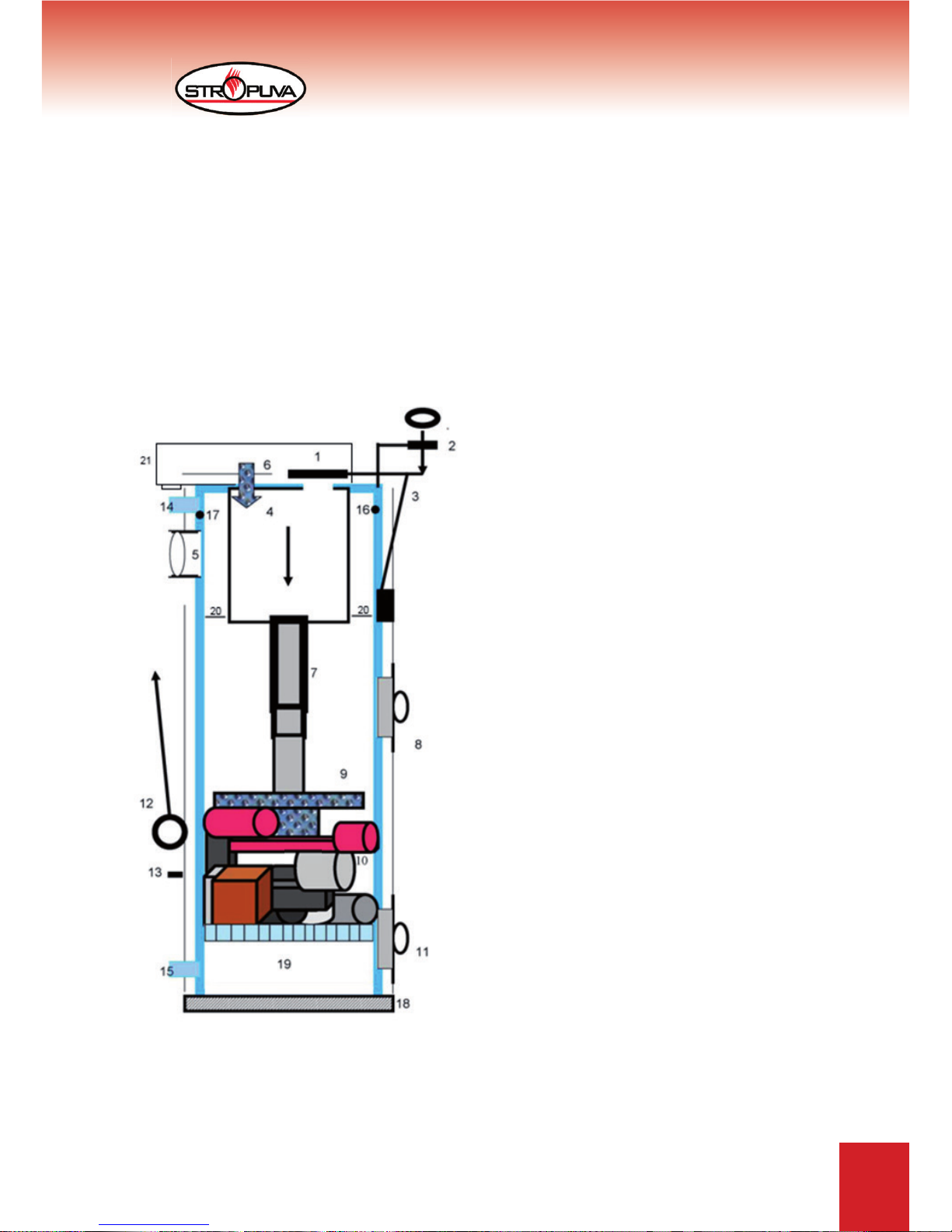
pav.1
1. Air valve
2. Draft regulator
3. Support rod
4. Air heating chamber
5. Smoke removal opening
6. Switch valve
7. Telescopic pipe of air injection
8. Door for loading of fuel
9. Air distributor with combustion chamber
stabilizer
10. Fuel
11. Door for ash removal
12. Lifting cord with ring
13. Hook
14. Pipe of hot water
15. Pipe of return water
16. Socket for thermometer
17. Socket for pressure safety valve 1,5 bar
18. Bottom
19. Fire grate
20. Defl ectors
21. Air injection collector
**Power of boiler is selected according to heated space. For example if in Stropuva S20
solid fuel boiler built in 200m
2
building one fuel load burns 24 hours than one load of fi rewood in
Stropuva S40 solid fuel boiler burns almost for 48 hours (35-40 hours). Solid fuel boiler Stropuva
S10 could be used, but warming up of building would take longer and fuel load would need to
be added 2-3 times in 24 hours.
***Duration of burn of one load depends on the quality of fuel, inside and outside temperature,
thermal resistance, boiler power, adherence to recommendations of user manual (boiler
installation, fl ow of heated water, maintenance of water temperature).
ATENTTION! It is forbidden to change the construction of boiler.
Figure 1
6
TECHNICAL PASSPORT INSTALLATION AND MAINTENANCE INSTRUCTIONS
2.1 DESCRIPTION OF BOILER STRUCTURE
Boiler is cylinder made of steel, enveloped in a cylinder of steel of bigger diameter and this
whole construction is thermally insulated. Heated water resides between these two cylinders.
At the front part of boiler there is draft regulator (2) (more information in 7.3). Construction has
openings for loading of fuel (8) and removal of ashes (11) as well as fl ue for smoke removal
(5). Also there are openings for water supply pipe (14 – 15), thermometer (16) and pressure
safety valve (17). At the top part of combustion there is air pre-heating chamber (4) chamber for
enhancement of burn quality and heat transfer. Telescopic air supply pipe (7) for attaching air
distributor and combustion chamber stabilizer, fi ts into this chamber (9).
“U” boiler is designed for peat briquettes or coal; it has switching valve (6) and is supplied
with fi re grate (19) and air injection collector (21).
“BIO” boiler is designed for fi rewood, pellets, and sawdust briquettes or wood chips. It is
supplied with fi re grate (19) and air injection collector (21).
At the upper part of chamber there is opening for air and air valve (1). On the right side of
the boiler, in front of the door, there is a cord and ring (12) for lifting of air supply mechanism
and fi xation hook (13).
Purpose of air distributor with stabilizer of combustion chamber (9) is to distribute air
correctly into generation zones, which are under and besides the air distributor, also in
burning zones. Air distributor with combustion chamber stabilizer (9) rests on fi rewood
which is on the sides and is not reaching high temperatures.
Distributor with stabilizer of combustion chamber (9) shouldn’t be moved during the burning:
if air distributor is lifted and lowered again, it rotates and falls deep into point of burning, than
boiler operates ineffi ciently and the lifespan of its parts is shortened.
3 PARTS OF BOILER
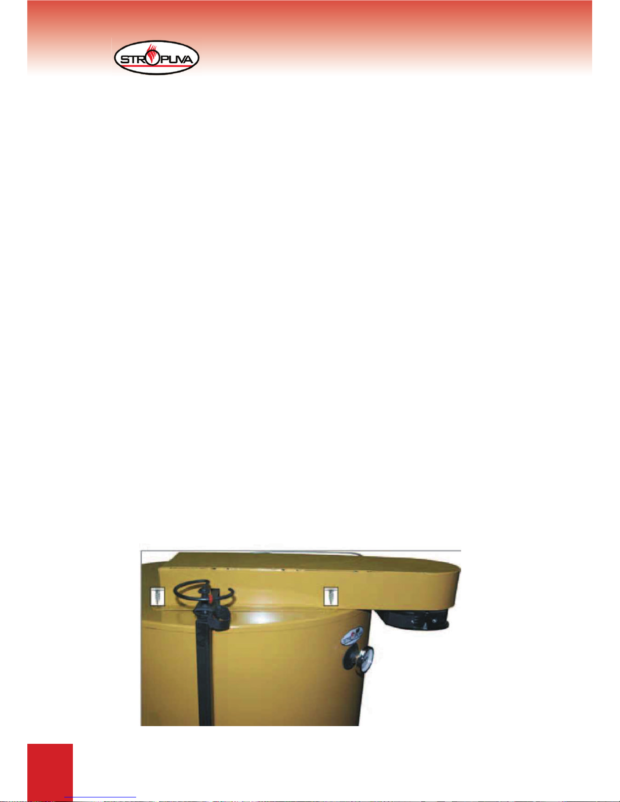
3.1 AIR INJECTION COLLECTOR (Figure 2)
With pellets, briquettes, damp fi rewood or other wood fuel and its residues we recommend
to use air injection collector. Air injection collector is mandatory when burning coal and peat. “U”
and “BIO” models come with air injection collector.
Air injection collector is plugged into electrical network after igniting the boiler and closing
the door.
Figure 2
7
TECHNICAL PASSPORT INSTALLATION AND MAINTENANCE INSTRUCTIONS
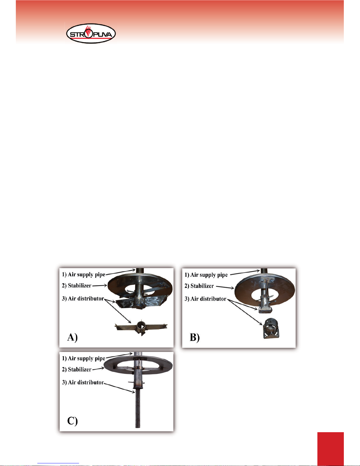
3.2 AIR DISTRIBUTOR WITH BURNING CHAMBER STABILIZER
(Figure 3)
Burning chamber stabilizer is mounted (fi g. 3), on the smallest part of telescopic air supply
pipe (7) (fi g. 1), it is integral in new boilers. We also developed units for repairs that consist of
two parts. If telescopic air supply pipe (7) (fi g. 1) has three holes, then stabilizer is locked in third
hole with a pin, if it has only one hole, additional hole must be drilled 55mm from the existing
hole. After mounting the stabilizer, air distributor can be mounted (fi g. 3). When burning pellets,
small fi rewood, distributor must be mounted on middle hole, so that space between the end of
air supply pipe (7) (fi g. 1) and distributor would be reduced to 5 – 7 mm.
A) We recommend using distributor with combustion chamber stabilizer (fi g. 3) when burning
fi rewood, briquettes. This burner is included with fi rewood boilers.
*Developer retains the right to alter and improve the construction of air distributor.
B) We recommend using distributor with combustion chamber stabilizer (fi g. 3) when burning
fi rewood, briquettes and pellets. We also recommend using air injection collector (fi g. 2) with this
burner. This distributor is used with “U” and “BIO” boilers.
*Developer retains the right to alter and improve the construction of air distributor.
C) We recommend using distributor with combustion chamber stabilizer (fi g. 3) when burning
peat and coal. We also recommend using air injection collector (fi g. 2) with this burner. This
distributor is used with “U” boilers.
*Developer retains the right to alter and improve the construction of air distributor.
When fuel burns, ash gather under air distributor with combustion chamber stabilizer (fi g. 3),
but it does not obstruct the burn, on the contrary – it protects the part from heat. Do not lift air
distributor with combustion chamber stabilizer (fi g. 3) when it is not necessarily needed,
this way you will increase its lifespan!!!
Figure 3
8
TECHNICAL PASSPORT INSTALLATION AND MAINTENANCE INSTRUCTIONS
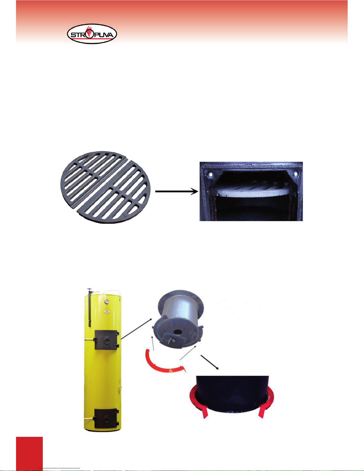
3.3 FIRE GRATE (fi gure 4)
Use fi re grate (19) (fi g. 1); (fi g. 4), when burning pellets, coal, peat and sawdust briquettes.
After opening the bottom door (11) (fi g. 1), it needs to be hanged on hooks at the bottom of
boiler. You will fi nd fi re grate (19) (fi g. 1); (fi g. 4) inserted, after you open the bottom door for ash
removal (11) (fi g. 1). In “U” boiler this part is used to get additional air inside through the channel
at the bottom of boiler, which is needed when burning coal and peat briquettes. In “BIO” boiler it
is needed to completely burn formed cinder. Put the fi re grate (19) (fi g. 1); (fi g. 4), on the bottom
of universal and “BIO” boiler when burning wood. This part is included with “U” and “BIO” solid
fuel boilers “Stropuva”.
3.5 DEFELCTORS (fi gure 5)
Defl ectors (crescent) 2 pcs. (fi g. 5) are designed to increase the effi ciency of boiler. After
mounting the defl ectors (20) (fi g. 1) we recommend putting it in through upper door, for loading
fuel, (8) (fi g. 1) on the bottom edge of inner air preheating tank.
Figure 4
Figure 5
9
TECHNICAL PASSPORT INSTALLATION AND MAINTENANCE INSTRUCTIONS
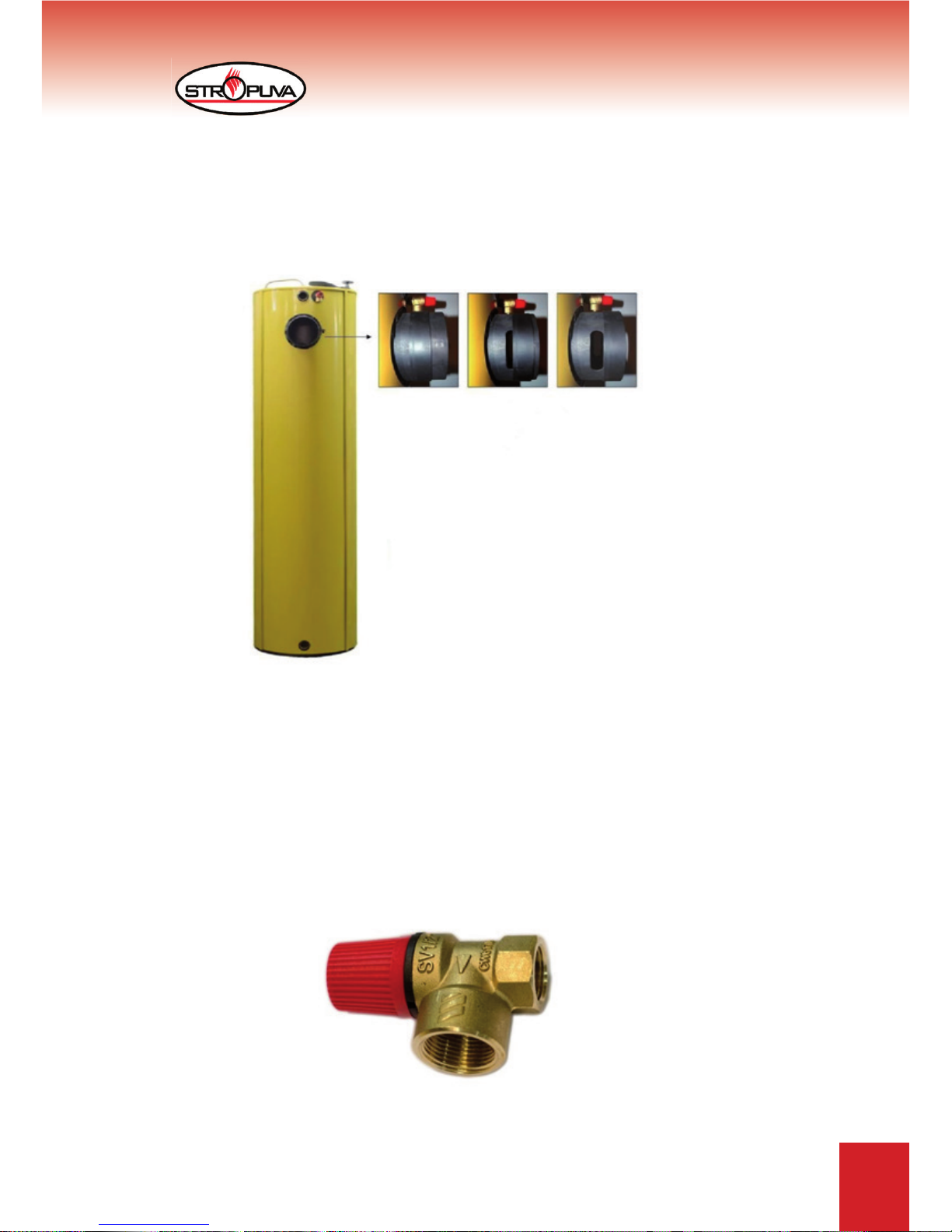
3.5 FLUE RING (fi gure 6)
If there is excessive draft in boiler, use valve (fl ue ring) (fi g. 6) to add additional air from boiler
room. Flue ring is on the opening used for boiler smoke removal (5) (fi g. 1). Flue hole must be
open in order to reduce draft and vibration. In order to increase draft – use fl ue ring (fi g. 6) to
close the hole.
3.6 SAFETY VALVE (1.5 BAR)
Valve is designed to protect solid fuel boilers from overheating. Valve opens when pressure
of water reaches dangerous value, then hot water is released in to sewerage, at the same time,
cold water from water supply is added through automatic system.
Valve must be mounted at the upper part of boiler (17) (fi g. 1) near the fl ue (see 6.2; 6.3; 6.4;
in connection diagrams No. 23). Cold water from water supply system is connected to system
of automatic water addition, which is connected to water return line of heating system, near the
boiler.
ATTENTION! Operation of safety valve must be inspected once a month.
Figure 6
Figure 7
 Loading...