

Stropuva DOMESTIC SOLID FUEL BOILER, S7, S10, S20, S40 Operating Manual
...
DOMESTIC SOLID FUEL BOILER
STROPUVA
INSTALLATION AND MAINTENANCE
MANUAL
CERTIFICATE NO. SPSC-672

CONTENT
1. DIMENSIONS AND CHARACTERISTICS ......................................................................................... 4
1.1 WOOD-FIRED BOILERS .............................................................................................................. 4
1.2 COAL-FIRED BOILERS ................................................................................................................ 5
2. DESCRIPTION OF A STRUCTURE .................................................................................................... 6
3. TRANSPORTATION AND WAREHOUSING .................................................................................... 7
4. BOILER FITTING ................................................................................................................................. 7
4.1. FIRE REQUIREMENTS ................................................................................................................ 8
4.2. REQUIREMENTS FOR THE CHIMNEY FLUE .......................................................................... 8
4.3. REQUIREMENTS FOR CONNECTING TO THE HEATING SYSTEM .................................... 9
4.4 MOUNTING PICTURE OF SOLID FUEL BOILER STROPUVA S40 NODE WITH THE
LOST OF PARTS .................................................................................................................................... 10
4.5. DESCRIPTION OF HEATING SYSTEM SCHEME OPERATION .......................................... 12
4.6 MOUNTING PICTURE OF SOLID FUEL BOILER STROPUVA S40 NODE WITH THE
LOST OF PARTS .................................................................................................................................... 13
4.7. DESCRIPTION OF SCHEME OPERATION WITHOUT ADDITIONAL BOILER AND
FLOOR HEATING .................................................................................................................................. 15
5. BOILER BURNING AND KINDLING ............................................................................................... 16
5.1. THE MOST ECONOMICALLY FUEL BURNS DOWN IN THE BOILER WHEN IT IS
FULLY LOADED ................................................................................................................................... 16
5.2. SETTING OF THE BI-THERMAL DRAUGHT REGULATOR ................................................ 18
5.3. EVALUATION OF THE BOILER OPERATION ....................................................................... 20
5.4. BOILER CLEANUP AND MAINTENANCE ............................................................................. 20
6. ACCIDENT PREVENTION REQUIREMENTS ................................................................................ 21
7. RISK ASSESSMENT .......................................................................................................................... 22
7.1. HEAT HAZARDS ........................................................................................................................ 22
7.2. PRESSURE HAZARDS ............................................................................................................... 23
7.3. POSSIBLE INTOXICATION ....................................................................................................... 23
7.4. REQUIREMENTS FOR CONNECTING OF ELECTRIC PARTS ............................................. 23
DEAR CUSTOMER,
We are delighted that you have put your trust in us.
We present the domestic solid fuel boiler, in the mouth of
which the burning time of one load is measured in days. With one
load of wood, peat and sawdust briquettes the boiler burns for
about 30 hours and with coal, the burning time is about 7 days.
Exceptional characteristics of the manufactured products, which
prolong the burning time of the solid fuel boiler, are the distribution
of air from the top and the solid fraction burning in the candle
principle.
Before installing and using it, we would ask that you read this
Manual carefully and follow the Instruction closely, as this will
guarantee better results when using the appliance.
Keep this Instruction Manual in a safe place so that you can
refer to it easily and thus abide by the guarantee conditions.
You should keep the Guarantee Certificate or, where relevant,
the technical datasheet, together with the Instruction Manuak for the
duration of the useful life of the appliance. It has important technical
information about the appliance.
Solid fuel heating boilers STROPUVA (hereinafter referred to as “the boiler”) are intended for
various premises/rooms where a central heating system is installed with radiators, heat water boiler for
domestic purposes or floor coils or heaters, or all together for heating. The system can be both with
natural and forced circulation, closed or opened.

1. DIMENSIONS AND CHARACTERISTICS
1.1 WOOD-FIRED BOILERS
Table 1.1. Dimensions and characteristics for wood-fired boilers.
Solid fuel: firewood logs, timber waste,
sawdust briquettes.
(Recommended moisture - ≤30%)*
MODEL
PARAMETRES
S7
S10
S20
S40
Power (kW)
7
10
20
40
Heated area (m2)
20-80
50-100
100-250
200-450
Fuel capacity (dm3)
150
200
350
500
Amount of firewood (kg)
15
25
50
80
Length of firewood (cm)
30-35
30-35
35-45
45-55
Water amount in the boiler (l)
26
34
45
58
Water temperature in the boiler (°C)
70
70
70
70
Coefficient of useful operation (%)
91,6
Flow of heated water (m3/h)
0,2
0,25
0,5
1,0
Dimension of load opening (mm)
250x210
250x210
260x220
280x240
Height (mm)
1250
1900
1900/2100
1900/2100
Diameter (mm)
450
450
560
680
Mass (kg)
100
185
231
315
* - Firewood containing more than 30 % moisture shall not burn at all and if burn – shall not endure
the required temperature, the burning shall be unstable. Combustion duration of fuel loading depend on its
quality, outside and inside temperature, building quality and other factors.
Table 1.2. Information for adjusters.
MODEL
Distance
between
floor and
chimney
(mm)
Chimney
diameter
(mm)
Distance
between
floor and
lower muff Ø
32 (mm)
Distance
between
floor and
upper muff Ø
32 (mm)
Pressure
valve (bar)
Water
pressure no
more than
(bar)
S7
1010
140
27.5
1187.5
1,5
2
S10
1430
160
12.5
1717.5
1,5 2 S20
1550
180
23.5
1936.5
1,5
2
S20 (1.9m)
1410
180
27.5
1727.5
1,5 2 S40
1550
200
38
1913
1,5
2
S40 (1.9 m)
1400
200
40
1710
1.5
2
1.2 COAL-FIRED BOILERS
Table 1.3. Dimensions and characteristics for coal-fired boilers.
Solid fuel: firewood logs, timber waste,
sawdust and peat briquettes, coal.
(Recommended moisture - ≤30%)*
MODEL
PARAMETRES
S10 U
S20 U
S40 U
Power (kW)
10
20
40
Heated area (m2)
50-100
100-200
180-400
Fuel capacity (dm3)
200
350
500
Amount of coal (kg)
Amount of firewood (kg)
75
25
130
50
220
80
Length of firewood (cm)
30-35
35-45
45-55
Water amount in the boiler (l)
34
45
58
Water temperature in the boiler (°C)
85
85
85
Coefficient of useful operation (%)
91,6
Flow of heated water (m3/h)
0,25
0,5
1,0
Dimension of load opening (mm)
250x210
260x220
280x240
Height (mm)
1900
1900/2100
1900/2100
Diameter (mm)
450
560
680
Mass (kg)
196
246
333
* - Firewood containing more than 30 % moisture shall not burn at all and if burn – shall not endure the
required temperature, the burning shall be unstable. Combustion duration of fuel loading depend on its
quality, outside and inside temperature, building quality and other factors.
Table 1.4. Information for adjusters.
MODEL
Distance
between
floor and
chimney
(mm)
Chimney
diameter
(mm)
Distance
between
floor and
lower muff Ø
32 (mm)
Distance
between
floor and
upper muff Ø
32 (mm)
Pressure
valve (bar)
Water
pressure no
more than
(bar)
S10 U
1550
160
57.5
1737.5
1.5
2
S20 U
1695
160
57.5
1947.5
1.5
2
S20 U
(1.9m)
1530
160
57.5
1747.5
1.5
2
S40 U
1675
180
57.5
1947.5
1.5
2
S40 U
(1.9 m)
1520
180
57.5
1747.5
1.5
2
6
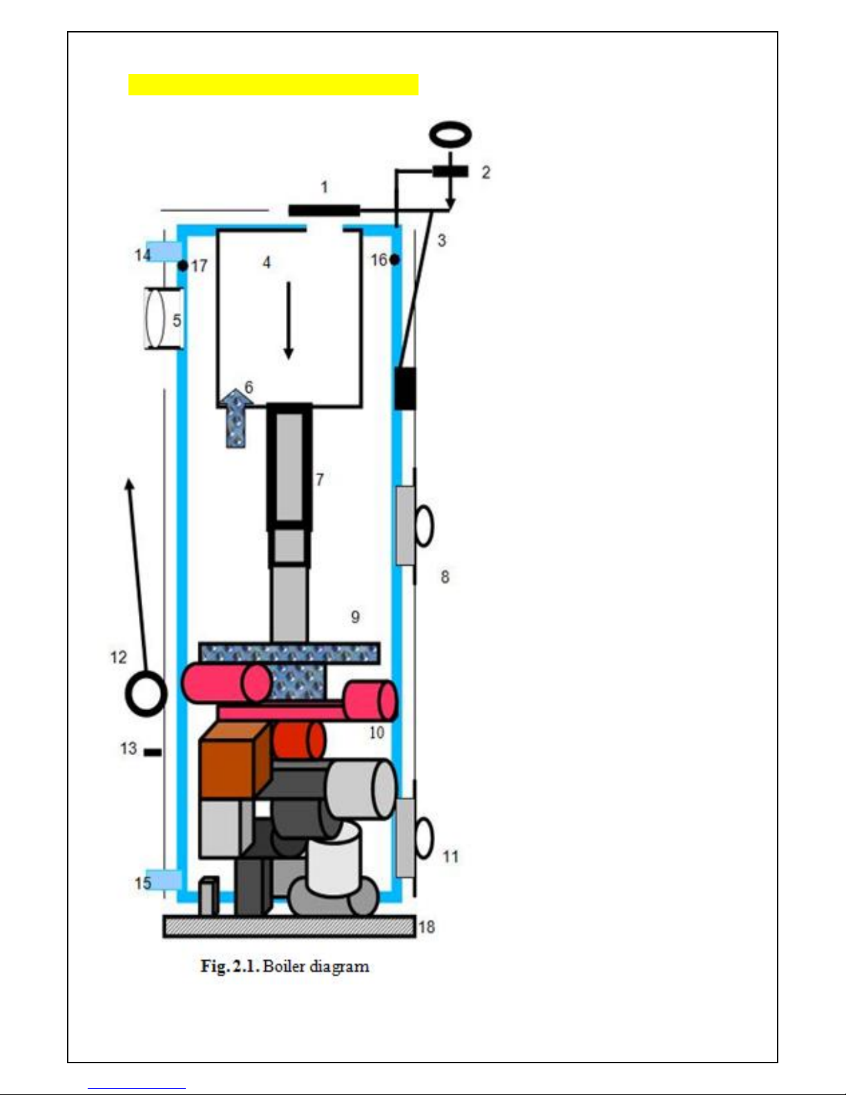
2. DESCRIPTION OF A STRUCTURE
The boiler (see figure 2.1.) is a
steel cylinder covered by a steel
cylinder of a bigger diameter, a
structure isinsulated. Bi-thermal
draught regulator (2) with wooden
stick (3) is at the front side of the
boiler (see for details item No. 5.2.).
Heated water is between the cylinders.
A structure has openings for loading
(8) of solid fuel (10), ash removal (11)
and smoke extraction flue (5). There
are also openings for water supply (14
- 15), thermometer (16) and pressure
safety valve (17). Air heating
compartment (4) for the improvement
of combustion quality and heating
transmission is mounted on the upper
part of a combustion compartment.
The boiler can be configured with grid
bars and switching valve (6) for
burning with peat or coal.
There is a gap between a
heating compartment and boiler
walls through which smoke pours so
that the heat would be better
transmitted. A telescope air feeding
pipe (7) fits into a compartment at the
end of which the air distributor is
fixed (9).

7
An opening for air injection and regulating valve (1) is at the upper part of a compartment. Upon
request, a concrete bottom with an insulating band is configured with the boiler (18). Lift cable (12) with
a ring of the air feeding mechanism is placed at the right side of the boiler in front of the door (a fixing
hook (13).
The purpose of the air distributor is to distribute correctly the air in the generation zones
below and near the air distributor, at the combustion zone near and above the distributor. Air
distributor leans upon the side firewood logs which do not get heated up to a high temperature.
It is no allowed to move a distributor during the combustion: after moving the air distributor up and
down, it turns and sinks deep into the combustion place and then the boiler operation is uneconomic, its
parts worn out more.
3. TRANSPORTATION AND WAREHOUSING
Boilers are allowed to be transported unfastened only in a horizontal position. If it does not rain, it is
allowed to transport with an open transport, in other cases it must be transported with a covered transport.
When transporting in a vertical position additional protection measures must be taken so that the boilers
won„t fall and scratch. Boilers can be stored in dry premises free of chemical active agent steam.
4. BOILER FITTING
The boiler is fitted in the premises corresponding to the state requirements established for the
premises of boiler houses. Premises where a boiler will be fitted must be at least 215 m in height and with
concrete flooring (at least in that place where the boiler will be erected). Premises must be made
watertight and protected from heated residential rooms and would have a vertical ventilation channel and
window or opening in the outside wall so that he air from outside would pass into the boiler and
ventilation channel. Using a mirror examine the inside of the chimney flue through the chimney flue
cleanup opening. The chimney flue must be clean. There must be no fittings nor bird nests and unsealed
openings leading to cavity ceilings and adjacent mines. It is verified whether the chimney flue does not
have openings or cracks in the outside through which the parasitic air can pass which will cool the
chimney flue and reduce its draught. Cracks, openings and a place where the boiler is connected to the
chimney flue must be sealed. If there are inner openings in the chimney flue leading to ceilings or adjacent
mines/shafts and there is no possibility to repair them, an oval or cylinder insert of stainless steel must be
fitted in. (Rectangular inserts are not reliable due to cracks formed in connection places due to
temperature changes). The boiler is erected straight on concrete floor; any cracks between the floor and
the boiler are sealed with heat resistant silicone or lime-cement solution with sand or other materials. The
boiler can be erected on a concrete bottom intended for fitting with an insulation rope.

8
During carrying sometimes parts of the boiler get deformed therefore when it is fitted into the
chimney flue and after closing all the doors and also the opening of the chimney flue cleanout opening,
check the operation of the upper valve, its nestling against surface of the air intake opening and doors
insulation using the flame of a candle or match.
4.1. FIRE REQUIREMENTS
The boiler is erected on a non flammable base. Metal connection of the boiler near the chimney
must be produced from metal not thinner than 1,5 mm and coated with heat insulation materials. The
condition of the chimney flue must be checked once per month (by examining it during the day time
through the cleanup opening with a mirror), in the event of necessity – clean it since soot and tars build up
in the chimney flue can ignite, throw the sparks, cause fire hazard, overheat or damage the insert. Using
branded chimney flues (of stainless steel or ceramic), study the users‟ manual and fulfill the requirements,
cleaning periodicity in particular. When the chimney flue is cleaned up, a horizontal flue between the
boiler and chimney flue must be cleaned up either.
4.2. REQUIREMENTS FOR THE CHIMNEY FLUE
The cross-width of the chimney flue opening can be 10 percent less as it is specified in the main
technical requirements but not bigger. The boiler requires an individual chimney flue; any other devices
cannot be connected to it. So that the formed condensate in the chimney flue would not get into the boiler,
a flue from the boiler to the chimney flue must be horizontal and not longer than 1.5 m and not shorter
than 0.20 m, well sealed and insulated with a heat insulation material in the connection places. Flue and
chimney flue is periodically cleaned up considering the mentioned above fire requirements.
It is recommended:
to fit in the chimney the insert of stainless steel; an orderly and correctly fitted insert protects
the chimney against the effect of condensate or moister;
an insert must not minimize significantly the cross section of the chimney opening; parts of
the insert must be tightly interconnected (with stainless steel rivets);
ash collector must be mounted below, collector must be mounted 15-20 cm below the flue
connection to the chimney flue; then the flue can be easily cleaned up through it;
the gap of the chimney between an insert and chimney walls, at least outside the chimney, fill
with inflammable insulation materials. At the top a crack must be hermetically plastered and tin
coated with a slope (from the opening to the chimney side);
the chimney at the cold loft must be sealed with inflammable insulation materials.
 Loading...