

Page 1

RFID MODULE
Mifare Reader / Writer
SL030
User Manual
Version 3.0
January 14, 2016
StrongLink
Page 2

StrongLink SL030 3. 0
2
CONTENT
1. MAIN FEATURES .................................................................................. 3
2. PINNING INFORMATION ................................................................... 4
3. Device Operation ..................................................................................... 5
3-1. CLOCK AND DATA TRANSITIONS: .......................................................................................... 5
3-2. START CONDITION .................................................................................................................. 5
3-3. STOP CONDITION ..................................................................................................................... 5
3-4. ACKNOWLEDGE ....................................................................................................................... 5
3-5. BUSY STATE ............................................................................................................................. 6
3-6. DEVICE ADDRESSING .............................................................................................................. 6
3-7. WRITE OPERATIONS ............................................................................................................... 7
3-8. READ OPERATIONS ................................................................................................................. 7
4. COMMAND DESCRIPTION ................................................................ 7
4-1. FORMAT ................................................................................................................................ 7
4-2. Command Overview ............................................................................. 8
4-3. COMMAND LIST .................................................................................................................. 9
4-3-1. SELECT MIFARE CARD ......................................................................................................... 9
4-3-2. LOGIN TO A SECTOR ............................................................................................................. 9
4-3-3. DOWNLOAD KEY INTO SL030 .............................................................................................. 9
4-3-4. LOGIN SECTOR VIA STORED KEY ....................................................................................... 11
4-3-5. READ A DATA BLOCK .......................................................................................................... 11
4-3-6. WRITE A DATA BLOCK ........................................................................................................ 11
4-3-7. READ A VALUE BLOCK ........................................................................................................ 11
4-3-8. INITIALIZE A VALUE BLOCK ............................................................................................... 12
4-3-9. WRITE MASTER KEY (KEYA) ............................................................................................. 12
4-3-10. INCREMENT VALUE ........................................................................................................... 12
4-3-11. DECREMENT VALUE .......................................................................................................... 13
4-3-12. COPY VALUE ...................................................................................................................... 13
4-3-13. READ A DATA PAGE (ULTRALIGHT & NTAG203) .......................................................... 14
4-3-14. WRITE A DATA PAGE (ULTRALIGHT & NTAG203) ....................................................... 14
4-3-15. REQUEST FOR ANSWER TO SELECT (ISO14443-4) ......................................................... 14
4-3-16. EXCHANGE TRANSPARENT DATA (T = CL) .................................................................... 14
4-3-17. LED CONTROL.................................................................................................................. 14
4-3-18. POWER DOWN ................................................................................................................... 15
4-3-19. WRITE PERSO ................................................................................................................... 15
4-3-20. COMMIT PERSO ................................................................................................................ 15
4-3-21. GET FIRMWARE VERSION ................................................................................................. 16
4-3-22. TURN ON/OFF AUTO-DETECTION ..................................................................................... 16
5. DIFFERENCES FROM PREVIOUS VERSION .............................. 16
http://www.stronglink-rfid.com
Page 3
StrongLink SL030 3. 0
3
1. MAIN FEATURES
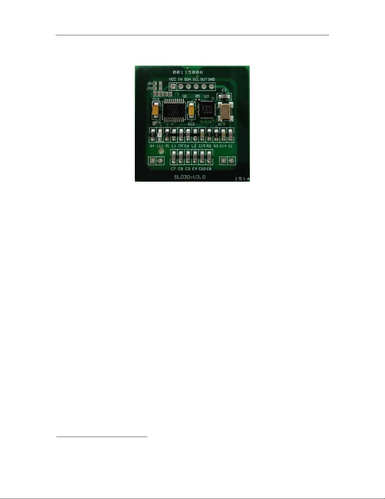
*This picture may not be exactly the same as real object.
• Tags supported: Mifare 1k, Mifare 4k, Mifare UltraLight, Mifare
UltraLight C, NTAG203, DESFire, DESFire EV1 and Mifare Plus
2K/4K
• Built-in antenna
• 0 to 400 KHz bit-wide I
2
C-bus communication
• 2.7 ~ 3.6V VDC operating, I/O pins are 5V tolerant
• Work current less than 45mA @3.3V
• Power down current less than 10uA
• Operating distance: Up to 50mm, depending on tag
• Storage temperature: -40 ºC ~ +85 ºC
• Operating temperature: -25 ºC ~ +55 ºC
• Dimension: 38 × 38 × 3 mm
• The OUT pin at low level indicates tag in detective range, and high
level indicating tag out
• Auto-detection: LED is on when card is in the detection range
1
Suppots all cards above except ISO14443-4 cards like DESFire/DESFire EV1 and MifarePlus L0/L2/L3. There is
Auto-detection command to control its on/off.
http://www.stronglink-rfid.com
1
Page 4
StrongLink SL030 3. 0
4
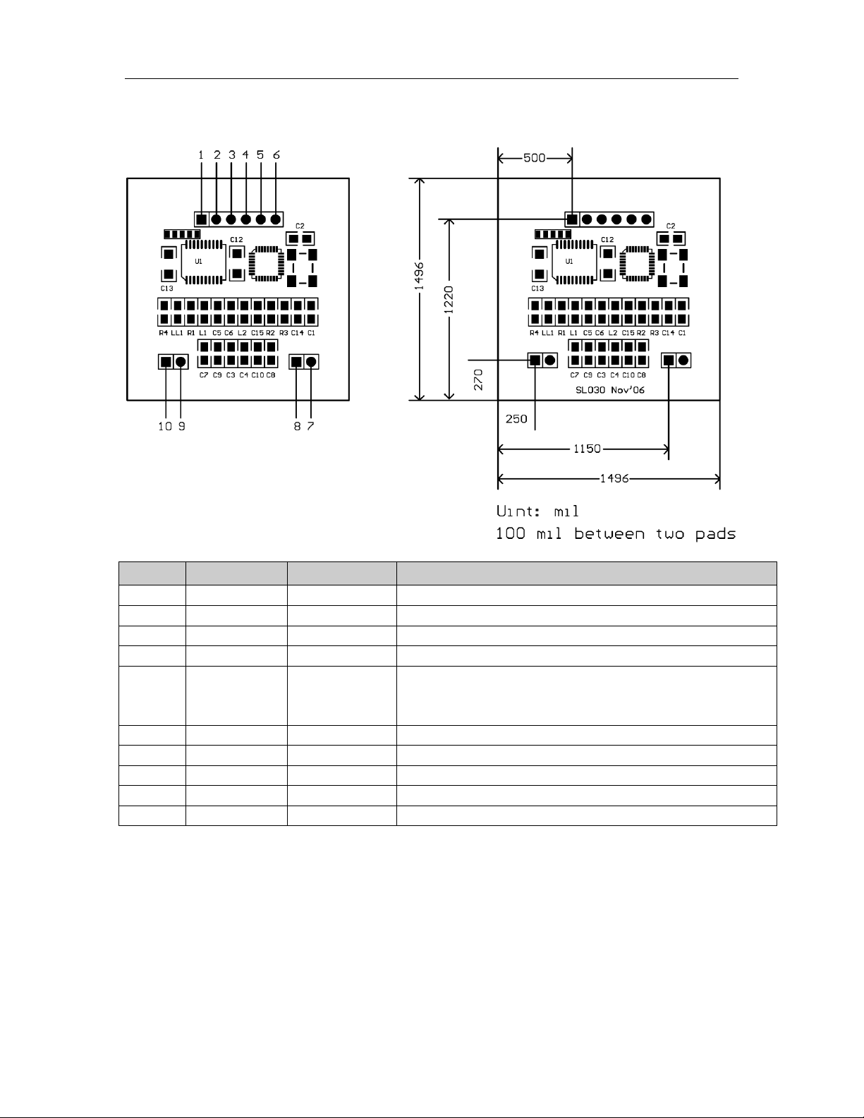
PIN
SYMBOL
TYPE
DESCRIPTION
1
VDD
PWR
Power supply, 2.7V to 3.6VDC
2
IN
Input
Falling edge wake up SL030 from power down mode
3
SDA
Input/Output
Serial Data Line
4
SLC
Input
Serial Clock Line
Tag auto-detection signal
high level indicating tag out
6
GND
PWR
Ground
7
NC 8 NC 9 NC
10
NC
2. PINNING INFORMATION
5 Out Output
Attention: Pin IN must be connected HIGH voltage when working, so SL030 can
enter power down mode properly.
low level indicating tag in
http://www.stronglink-rfid.com
Page 5
StrongLink SL030 3. 0
5
3. Device Operation
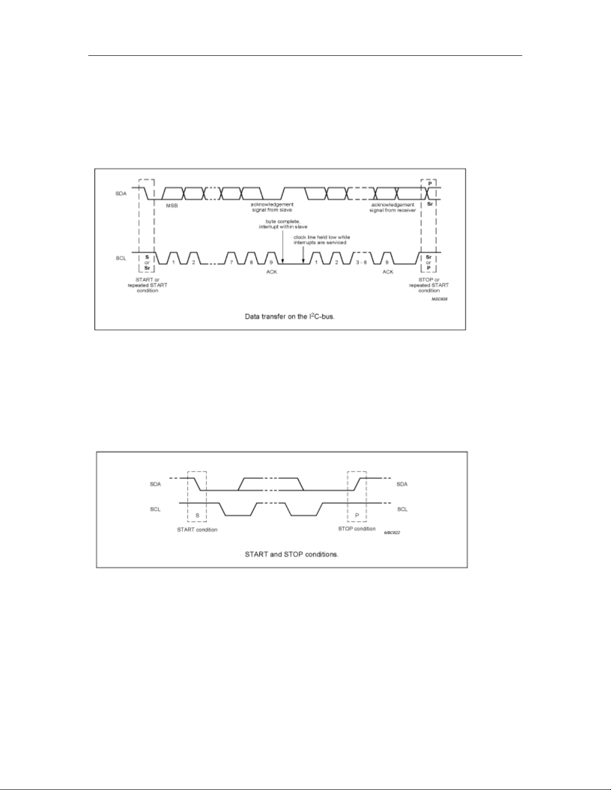
3-1. Clock and Data Transitions:
The SDA pin is normally pulled high with an external device. Data on the SDA pin may
change only during SCL low time periods. Data changes during SCL high periods will
indicate a start or stop condition a s defined below.
3-2. Start Condition
A high-to-low transition of SDA with SCL high is a start condition which must precede any
other command
3-3. Stop Condition A low-to-high transition of SDA with SCL high is a stop condition.
3-4. Acknowledge
All addresses and data words are serially transm itted to and from the SL030 in 8-bit words.
The SL030 sends a zero to acknowledge that it is not busy, and has received each word.
This happens during the ninth clock cycle.
http://www.stronglink-rfid.com
Page 6
StrongLink SL030 3. 0
6
JP1
JP2
Address
1010000
( default )
no
yes
1010001
yes
no
1010010
yes
yes
1010011
3-5. Busy State
When the SL030 has received command, then don’t acknowledge IIC bus until ends with
the card communication.
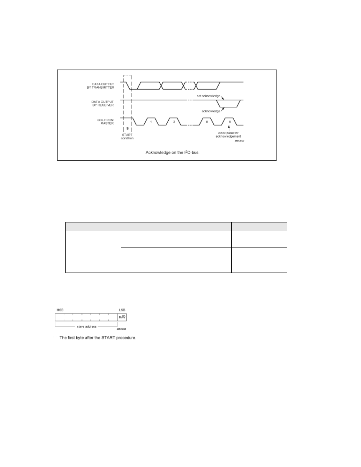
3-6. Device Addressing
The SL030 devices require an 8-bit device address word following a start condition to
enable the chip for a read or write operation.
The device address word consists of 7 bits addressing and 1 bit operation select bit.
The first 7 bits are the SL030 addressing, is 10100xx depend on JP1 and JP2 status as
below table
no no
shorted
The eighth bit of the device address is the read/write operation select bit. A read operation
is initiated if this bit is high and a write operation is initiated if this bit is low.
http://www.stronglink-rfid.com
Page 7
StrongLink SL030 3. 0
7
Address
Len
Command
Data
Address
Len
Command
Status
Data
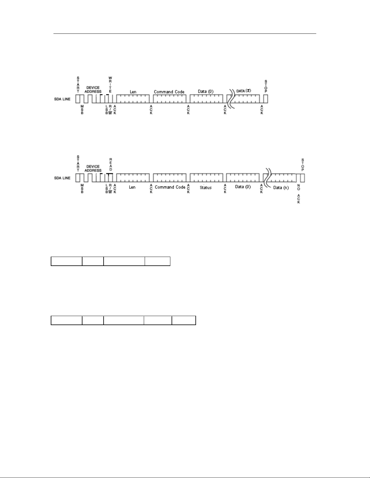
3-7. Write Operations
The host device send a command(refer chapter 4) t o SL030 v ia write operation, th en SL030
will carry out the order that receive. Finished time according to different order
3-8. Read Operations
The host device passes to read the operation gets the order carries out the result
4. COMMAND DESCRIPTION
4-1. FORMAT Host Write Command to SL030:
Address: 1 byte, 0xA0
Len: 1 byte indicating the number of bytes from Command to the end of Data
Command: 1 byte Command code, see Table 3
Data: Variable length depends on the command type
Host Read The Result:
Address: 1 byte, 0xA1
Len: 1 byte indicating the number of bytes from Command to the end of Data
Command: 1 byte Command code, see Table 3
Status: 1 byte Command status, see Table 4
Data: Variable length depends on the command type.
http://www.stronglink-rfid.com
Page 8

StrongLink SL030 3. 0
8
Command
Description
0x01
Select Mifare card
0x02
Login to a sector
0x03
Read a data block
0x04
Write a data block
0x05
Read a value block
0x06
Initialize a value block
0x07
Write master key (key A)
0x08
Increment value
0x09
Decrement value
0x0A
Copy value
0x10
Read a data page (Ultralight & NATG203)
0x11
Write a data page (Ultralight & NTAG203)
0x12
Download Key
0x13
Login sector via stored Key
0x20
Request for Answer to Select (ISO14443-4)
0x21
Exchange Transparent Data according to T = CL
0x40
LED control
0x50
Go to Power Down mode
0x80
MFP WritePerso
0x81
MFP CommitPerso
0xF0
Get firmware version
0xFE
Turn on/off Auto-detection
Status
Description
0x00
Operation succeed
0x01
No tag
0x02
Login succeed
0x03
Login fail
0x04
Read fail
0x05
Write fail
0x06
Unable to read after write
0x08
Address overflow
0x09
Download Key fail
0x0A
Collision occur
0x0C
Load key fail
0x0D
Not authenticate
0x0E
Not a value block
0x0F
Input len invalid
0x12
MFP WritePerso fail
0x13
MFP CommitPerso fail
0xF1
Invalid command
4-2. Command Overview
Table 3
STATUS OVERVIEW
Table 4
http://www.stronglink-rfid.com
Page 9
StrongLink SL030 3. 0
9
Len
0x01
Len
0x01
Status
UID
Type
Len
0x02
Sector
Type
Key
Len
0x02
Status
4-3. COMMAND LIST
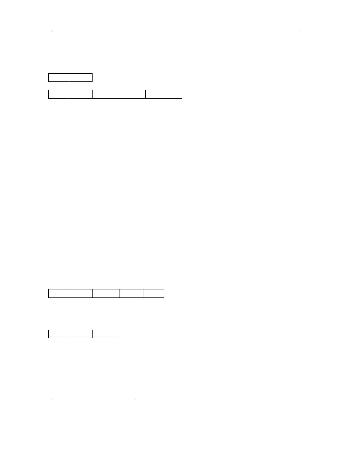
4-3-1. Select Mifare card Host Write:
Host Read:
Status: 0x00: Operation succeed
0x01: No tag
UID: The uniquely serial number of Mifare card
Type:
MFMini_4B 0x01
MFMini_7B 0x02
MF1K_4B UID/ MFPLUS2K SL1_4B UID 0x03
MF1K_7B UID/ MFPLUS2K SL1_7B UID 0x04
MF4K_4B UID/ MFPLUS4K SL1_4B UID 0x05
MF4K_7B UID/ MFPLUS4K SL1_7B UID 0x06
MF Ultralight/MF Ultralight C/Ntag 203 0x07
MF DESFire/MF DESFire EV1 0x09
MF PROX 0x0B
MFPLUS2K SL2_4B UID 0x21
MFPLUS4K SL2_4B UID 0x22
MFPLUS2K SL2_7B UID 0x23
MFPLUS4K SL2_7B UID 0x24
MFPLUS2K SL0/SL3_4B UID
MFPLUS4K SL0/SL3_4B UID 0x32
MFPLUS2K SL0/SL3_7B UID 0x33
MFPLUS4K SL0/SL3_7B UID 0x34
Other 0x00
4-3-2. Login to a sector Host Write:
2
0x31
Sector: Sector need to login, 0x00 – 0x27
Type: Key type (0xAA: authenticate with KeyA, 0xBB: authenticate with KeyB)
Key: Authenticate key, 6 bytes
Host Read:
Status: 0x02: Login succeed
0x01: No tag
0x03: Login fail
0x08: Address overflow
4-3-3. Download Key into SL030
2
Mifare Plus SL0 and SL3 can tell differences via ATS(ISO14443-4). Before ATS, they have the same ATQA and
SAK(ISO14443-3). SL030 judges card type only via ISO14443-3 layer for the compatibility.
http://www.stronglink-rfid.com
Page 10

StrongLink SL030 3. 0
10
Len
0x12
Sector
Type
Key
Len
0x12
Status
Host Write:
Sector: 0x00 – 0x27
Type: Key type (0xAA: KeyA, 0xBB: KeyB)
Key: 6 bytes, stored into SL030
Host Read:
Status: 0x00: Operation succeed
0x08: Address overflow
0x09: Download fail
Note: Some delay is needed between Host Write and Host Read.
http://www.stronglink-rfid.com
Page 11
StrongLink SL030 3. 0
11
Len
0x13
Sector
Type
Len
0x13
Status
Len
0x03
Block
Len
0x03
Status
Data
Len
0x04
Block
Data
Len
0x04
Status
Data
Len
0x05
Block
Len
0x05
Status
Value
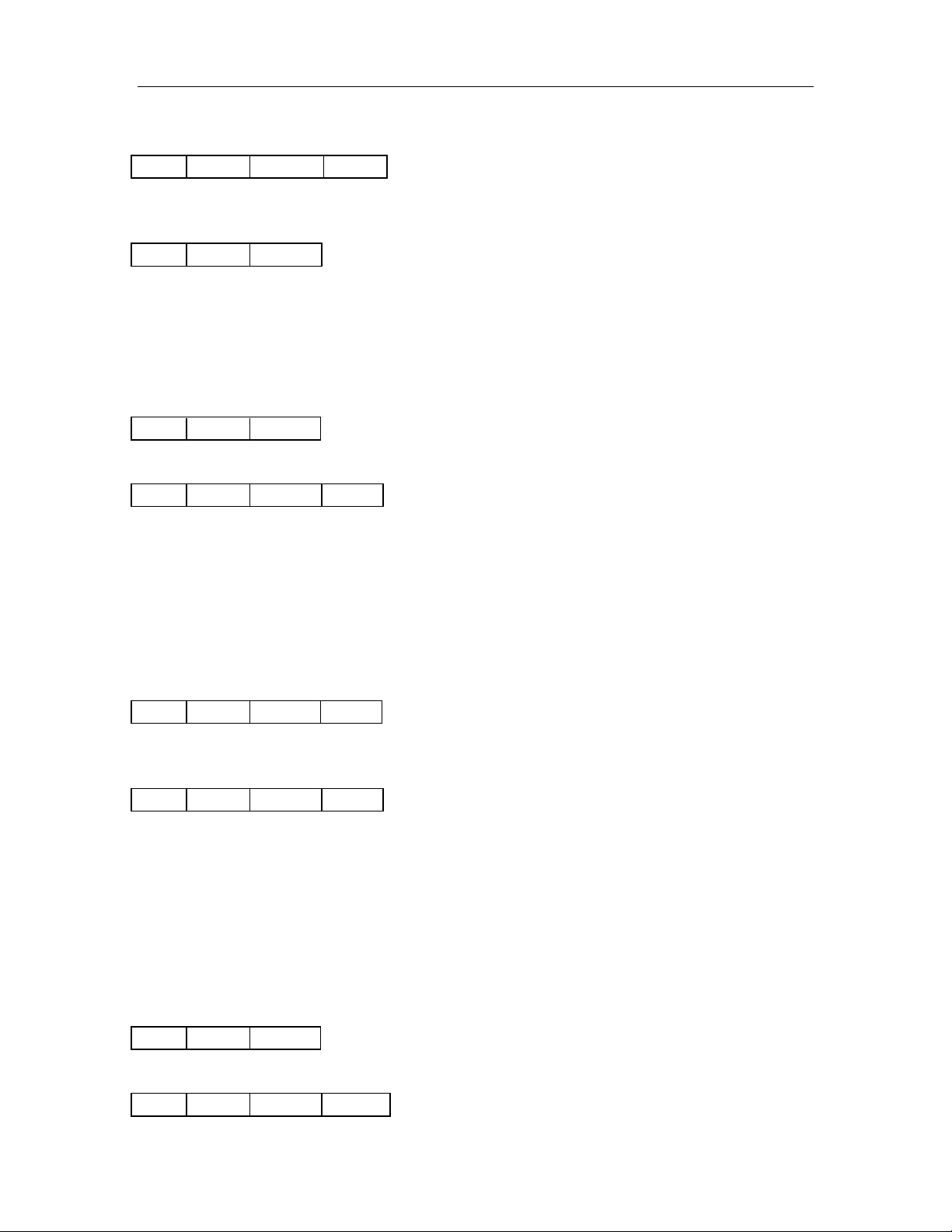
4-3-4. Login sector via stored key Host Write:
Sector: Sector need to login, 0x00 – 0x27
Type: Key type (0xAA: KeyA, 0xBB: KeyB)
Host Read:
Status: 0x02: Login succeed
0x03: Login fail
0x08: Address overflow
4-3-5. Read a data block Host Write:
Block: The absolute address of block to be read, 1 byte
Host Read:
Status: 0x00: Operation succeed
0x01: No tag
0x04: Read fail
0x0D: Not authenticate
Data: Block data returned if operation succeeds, 16 bytes.
4-3-6. Write a data block Host Write:
Block: The absolute address of block to be written, 1 byte.
Data: The data to write, 16 bytes.
Host Read:
Status: 0x00: Operation succeed
0x01: No tag
0x05: Write fail
0x06: Unable to read after write
0x0D: Not authenticate
Data: Block data written if operation succeeds, 16 bytes.
4-3-7. Read a value block Host Write:
Block: The absolute address of block to be read, 1 byte.
Host Read:
http://www.stronglink-rfid.com
Page 12
StrongLink SL030 3. 0
12
Len
0x06
Block
Value
Len
0x06
Status
Value
Len
0x07
Sector
Key
Len
0x07
Status
Key
Len
0x08
Block
Value
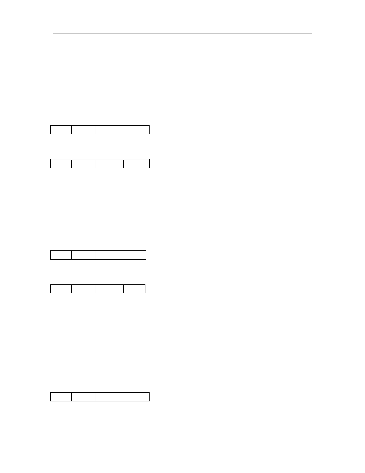
Status: 0x00: Operation succeed
0x01: No tag
0x04: Read fail
0x0D: Not authenticate
0x0E: Not a value block
Value: Value returned if the operation succeeds, 4 bytes.
4-3-8. Initialize a value block Host Write:
Block: The absolute address of block to be initialized, 1 byte.
Value: The value to be written, 4 bytes.
Host Read:
Status: 0x00: Operation succeed
0x01: No tag
0x05: Write fail
0x06: Unable to read after write
0x0D: Not authenticate
Value: Value written if the operation succeeds, 4 bytes.
4-3-9. Write master key (KeyA) Host Write:
Sector: The sector number to be written, 0x00 – 0x27.
Key: Authentication key, 6 bytes
Host Read:
Status: 0x00: Operation succeed
0x01: No tag
0x05: Write fail
0x08: Address overflow
0x0D: Not authenticate
Key: Authentication key written if the operation succeeds, 6 bytes.
Attention: Be sure KeyB is readable, otherwise KeyB will be change to 000000000000
after this command.
4-3-10. Increment value Host Write:
Block: The absolute address of block to be increased, 1 byte.
Value: The value to be increased by, 4 bytes.
Host Read:
http://www.stronglink-rfid.com
Page 13

StrongLink SL030 3. 0
13
Len
0x08
Status
Value
Len
0x09
Block
Value
Len
0x09
Status
Value
Len
0x0A
Source
Destination
Len
0x0A
Status
Value
Status: 0x00: Operation succeed
0x01: No tag
0x05: Write fail
0x06: Unable to read after write
0x0D: Not authenticate
0x0E: Not a value block
Value: The value after increment if the operation succeeds, 4 bytes
4-3-11. Decrement value Host Write:
Block: The absolute address of block to be decreased, 1 byte
Value: The value to be decreased by, 4 bytes
Host Read:
Status: 0x00: Operation succeed
0x01: No tag
0x05: Write fail
0x06: Unable to read after write
0x0D: Not authenticate
0x0E: Not a value block
Value: The value after decrement if the operation succeeds, 4 bytes
4-3-12. Copy value Host Write:
Source: The source block copy from, 1 byte
Destination: The destination copy to, 1 byte
The source and destination must in the same sector
Host Read:
Status: 0x00: Operation succeed
0x01: No tag
0x05: Write fail
0x06: Unable to read after write
0x0D: Not authenticate
0x0E: Not a value block (Source)
Value: The value after copy if the operation succeeds, 4 bytes
http://www.stronglink-rfid.com
Page 14
StrongLink SL030 3. 0
14
Len
0x10
Page
Len
0x10
Status
Data
Len
0x11
Page
Data
Len
0x11
Status
Data
Len
0x20
Len
0x20
Status
ATS
Len
0x21
Data
Len
0x21
Status
Data
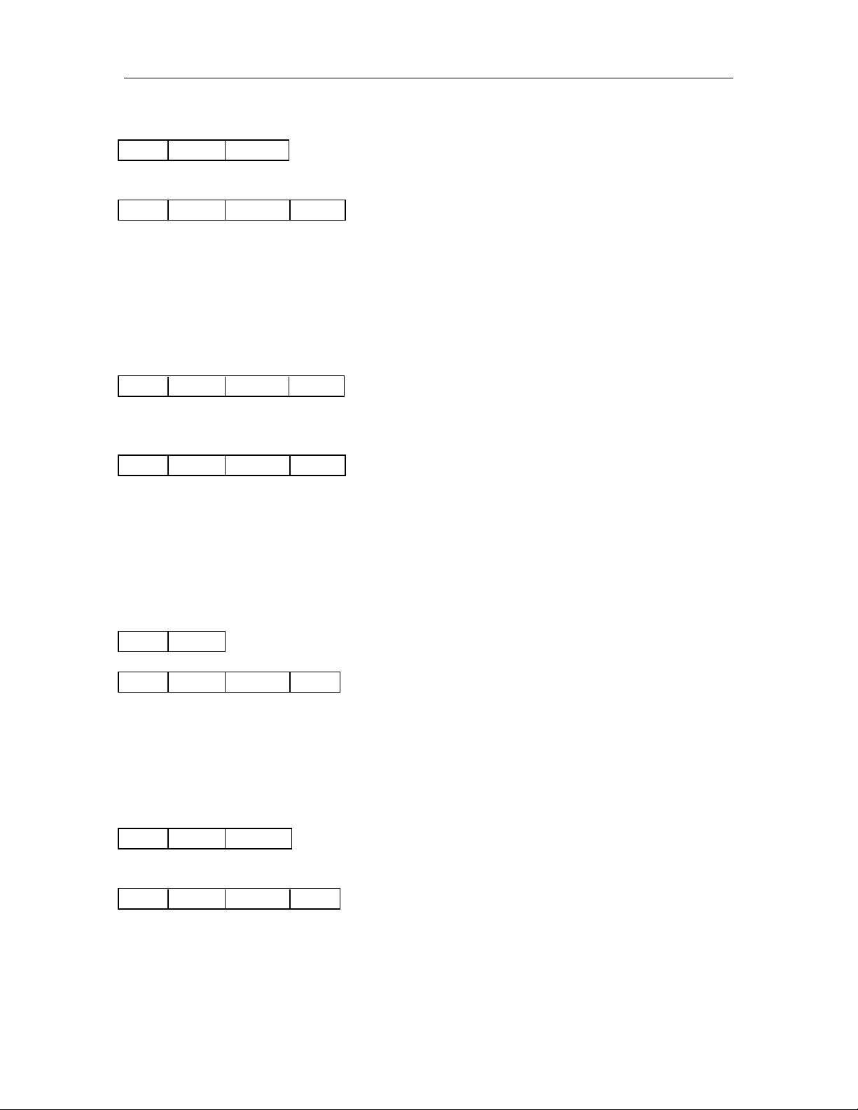
4-3-13. Read a data page (UltraLight & NTAG203) Host Write:
Page: The page number to be read, 1 byte
Host Read:
Status: 0x00: Operation succeed
0x01: No tag
0x04: Read fail
0x08: Address overflow
Data: Block data returned if operation succeeds, 4 bytes.
4-3-14. Write a data Page (UltraLight & NTAG203) Host Write:
Page: The page number to be written, 1 byte.
Data: The data to write, 4 bytes.
Host Read:
Status: 0x00: Operation succeed
0x01: No tag
0x05: Write fail
0x06: Unable to read after write
0x08: Address overflow
Data: page data written if operation succeeds, 4 bytes.
4-3-15. Request for Answer to Select (ISO14443-4)
Response:
Status: 0x00: Operation succeed
0x10: Address overflow
ATS: According to ISO14443-4 protocol
Len + T0 + TA1 + TB1 + TC1 + A1 + AK
4-3-16. Exchange Transparent Data (T = CL)
Data: COS command
Response:
Status: 0x00: Operation succeed
0x11: Communicate with card failed
Data: Response data from card
4-3-17. LED Control
http://www.stronglink-rfid.com
Page 15
StrongLink SL030 3. 0
15
Len
0x40
Data
Len
0x40
Status
Len
0x50
Len
0x50
Status
Len
0x80
Bnr
Data
Len
0x80
Status
Len
0x81
Len
0x81
Status
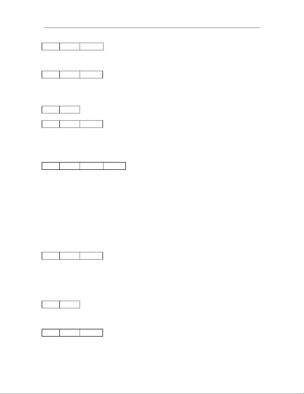
Host Write:
Data: 0x00: LED off
0x01: LED on
Host Read:
Status: 0x00: Operation succeed
4-3-18. Power Down Host Write:
Host Read:
Status: 0x00: Operation succeed
Note: Some delay is needed when waking up SL030.
4-3-19. Write Perso Host Write:
Bnr: 2Byte Block or Key Address to be written, MSB first.
For example,
Master Key Address is 0x9000, and write it as 0xFFFF..FF(16Bytes)
13809000FFFFFFFFFFFFFFFFFFFFFFFFFFFFFFFFh
Configuration Key Address is 0x9001, and write it as 0xFFFF..FF(16Bytes)
13809001FFFFFFFFFFFFFFFFFFFFFFFFFFFFFFFFh
Switch to Level 2 Key Address is 0x9002, and write it as 0xFFFF..FF(16Bytes)
13809002FFFFFFFFFFFFFFFFFFFFFFFFFFFFFFFFh
Switch to Level 3 Key Address is 0x9003, and write it as 0xFFFF..FF(16Bytes)
13809003FFFFFFFFFFFFFFFFFFFFFFFFFFFFFFFFh
Data: Value of the key or data
Host Read:
Status: 0x00: Operation succeed
0x11: Communicate with card failed
0x12: Card Write Perso failed
4-3-20. Commit Perso Host Write:
This command commit the Write Perso and switch the card to security level 1(SL1 card) o r
level 3(SL3 card).
Host Read:
Status: 0x00: Operation succeed
0x11: Communicate with card failed
0x13: Card Commit Perso failed
http://www.stronglink-rfid.com
Page 16
StrongLink SL030 3. 0
16
Len
0xF0
Len
0xF0
Status
Data
Len
0xFE
Data
Len
0xFE
Status
Attention: According to NXP MifarePlus card document, Commit Perso will make effect
after you have “Write Perso” the Master KEY, Configuration KEY and SWL3 KEY.
If your card is L1 card, after Commit Perso, the card will switch L0 to L1;
If your card is L3 card, after Commit Perso, the card will switch L0 to L3.
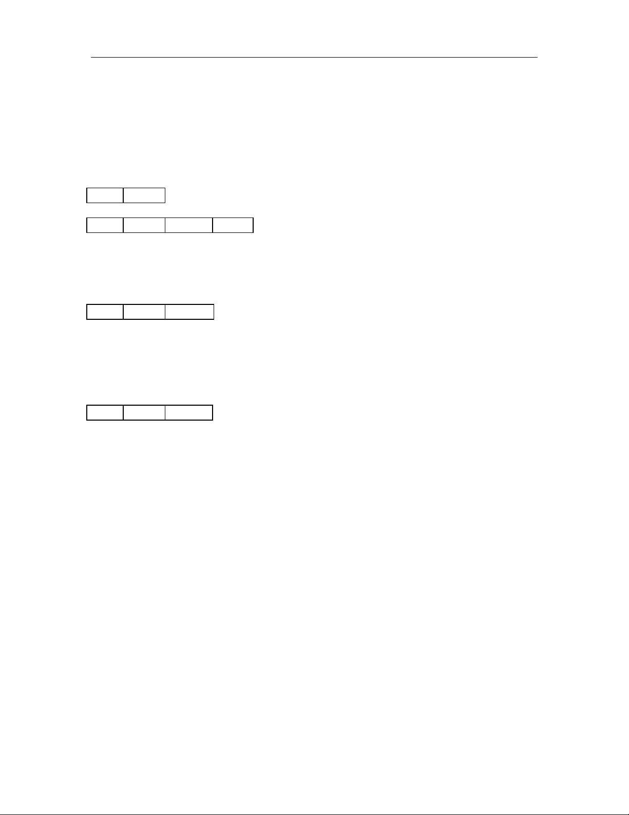
4-3-21. Get firmware version Host Write:
Host Read:
Status: 0x00: Operation succeed
Data: firmware version.
4-3-22. Turn on/off Auto-detection Host Write:
Data: 0x00: Turn off Auto-detection
0x01: Turn on Auto-detection
For example,
02FE00h // Turn off Auto-detection
02FE01h // Turn on Auto-detection
Host Read:
Status: 0x00: Operation succeed
5. DIFFERENCES FROM PREVIOUS VERSION
Although we make efforts on the compatibility between the new SL030 V3.0 and the
old SL030 V1.0-V2.3, there are still some differences you need to know.
1. New SL030 has a new auto-detection function which can close automatically when
there is a DESFire or MifarePlus L0/L2/L3 card coming into the detection range,
and the light will be on even if the card is out of field. By the way , we also of fer you
the Turn On/Off Auto-detection command.
2. New SL030 supports nearly all cards of NXP Mifare series now and we rebuilt the
card type characters.(Details see to Command Select Mifare Card Description)
http://www.stronglink-rfid.com
 Loading...