

Page 1

ULTRA 80
Xenon Lamphouse
Type 40001, 40002
Rev. 5/99
STRONG INTERNATIONAL
a division of Ballantyne of Omaha, Inc.
4350 McKinley Street
Omaha, Nebraska 68112 USA
Tel 402/453-4444 • Fax 402/453-7238
Page 2

Page 3

PREFACE
THE STRONG ULTRA 80 is a reflector type, direct current lamphouse for large format (70mm+) motion picture projection which uses a horizontally mounted xenon bulb as the light
source. Type 40001 is designed for use with the XH7000HS xenon bulb, and Type 40002, for the
XH10000V(H) bulb. Both type bulbs are manufactured by the Hanovia Division, ORC Lighting
Products, Azusa, California. The lamphouse reflector is a metal, deep ellipse type, with a “cold”
(dichroic) coating to reduce aperture heat and prolong bulb life. The reflector is designed to operate
in a fixed position 34½ to 35 inches from the projection film plane.
USE ONLY THE SPECIAL XENON POWER SUPPLIES manufactured by Strong
International. The 40001 lamphouse requires a power supply capable of providing 120-160 DC amperes at 43-49 V.DC. Nominal operating current for a 7000 watt bulb is 150 amperes; do not exceed
160 amperes. The xenon power supply used with the 40002 lamphouse must be capable of producing
135-200 DC amperes at 52-58 V.DC. The nominal operating current of a 10,000 watt bulb is 180
amperes; do not exceed 200 amperes. The xenon power supply must also include a 120 V.AC
lamphouse control circuit.
THE ADJUSTMENT CONTROL to position the xenon bulb in relation to the reflector is located on the rear of the lamphouse, behind the removable cover panel. This control permits
horizontal and vertical movement and focus control of the xenon bulb.
A TERMINAL STUD, located near the bulb anode support on the base pan of the
lamphouse, is provided as a connecting point for the lamphouse DC (+) lead and the anode lead
attached to the xenon bulb.
THE LAMPHOUSE CONTROL PANEL includes a DC ammeter to display the
operating current of the lamp. A pushbutton switch above the ammeter changes the reading to indicate the DC voltage at the arc. This capability permits calculation of the lamp power while the lamp
is operating (amperes x volts = wattage). Pressing the switch at ignition will also briefly display the
“no load” DC voltage.
AN ELAPSED TIME METER indicates the total number of hours the lamp has been
in service and provides a means of noting the number of hours each xenon bulb has operated. It is
advisable to replace the xenon bulb upon expiration of warranty hours. See the warranty information
provided by the manufacturer of the xenon bulb.
THE LAMP BLOWER(S), internally wired in the lamphouse, operate on AC voltage
and are required to maintain the seals of the bulb at a safe operating temperature. The top blower is
fused at 3 amperes. A second side-mounted blower is used on the T ype 40002 to cool the reflector for
10,000 watt operation. The blowers will operate continuously until control voltage is turned off at the
xenon power supply .
U80/001
Page 4

TWO AIR FLOW SWITCHES, mounted to the exhaust duct and the blower intake,
will prevent ignition of the lamp if the top blower is not operating, or the exhaust air flow is inadequate. The eight-inch lamphouse exhaust stack connects to an externally installed exhaust system.
The exhaust system must be capable of removing 700 cubic feet per minute (c.f.m.) of free air from the
lamphouse, as measured at the lamphouse exhaust outlet.
THE LAMPHOUSE has an interlock switch on the side access door and one under the
igniter cover on the top of the lamphouse. Opening the side door or removing the plastic igniter cover
will open the AC control circuit and prevent operation of the xenon lamp. The lamphouse door has a
viewing port to permit observation of the xenon arc.
THE IGNITER is equipped with an emergency ignition switch, located beneath the
plug button on the igniter access panel on the top of the lamphouse.
THE “MODE” rocker type switch on the rear of the lamphouse provides the means of
operating the equipment from a remote AUTO system, or when placed in the “MAN.” position, from
the lamphouse.
THE LAMP “ON - OFF” SWITCH on the lamphouse instrument panel is used for bulb
ignition when the MODE switch is in the “MAN.” position. For AUTO operation, the LAMP switch
remains in the “ON” position.
THE LAMPHOUSE DOUSER is provided to permit shutting off the light to the projector at changeover. The lamp should not be operated for any extended time with the douser closed.
The small intense spot of light on the douser plate may cause deterioration of the plate. An Electric
Douser Kit, connected to the projector motor, is available as an option. This option automatically
closes the douser when the projector motor is switched OFF.
THE ULTRA 80 is not designed for use with 35mm projection. The highly intense
radiant energy generated by high wattage xenon bulbs will damage 35mm prints.
IF AT ANY TIME you have a suggestion, or desire aid in securing anticipated results,
write STRONG INTERNATIONAL, 4350 McKinley Street, Omaha, Nebraska 68112.
U80/002
Page 5
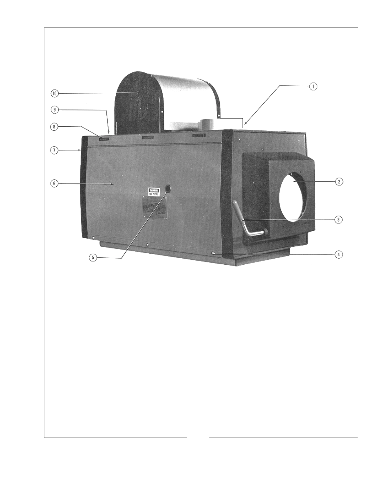
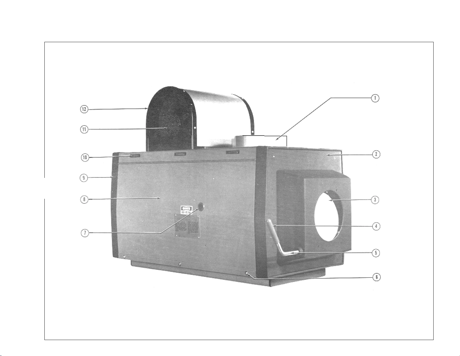
ULTRA 80 LAMPHOUSE
1. Exhaust Stack, 8 inch 6. Lamphouse Access Door
2. Douser Plate 7. Rear Casting & Instrument Panel
3. Douser Control Handle 8. Magnetic Door Catch (early models)
4. Tamperproof Screw 9. Emergency Ignition Switch*
5. Arc Viewing Port 10. Bulb Seal Blower
* Emergency Ignition Switch located below Plug Button on Access Plate.
U80/003
Page 6
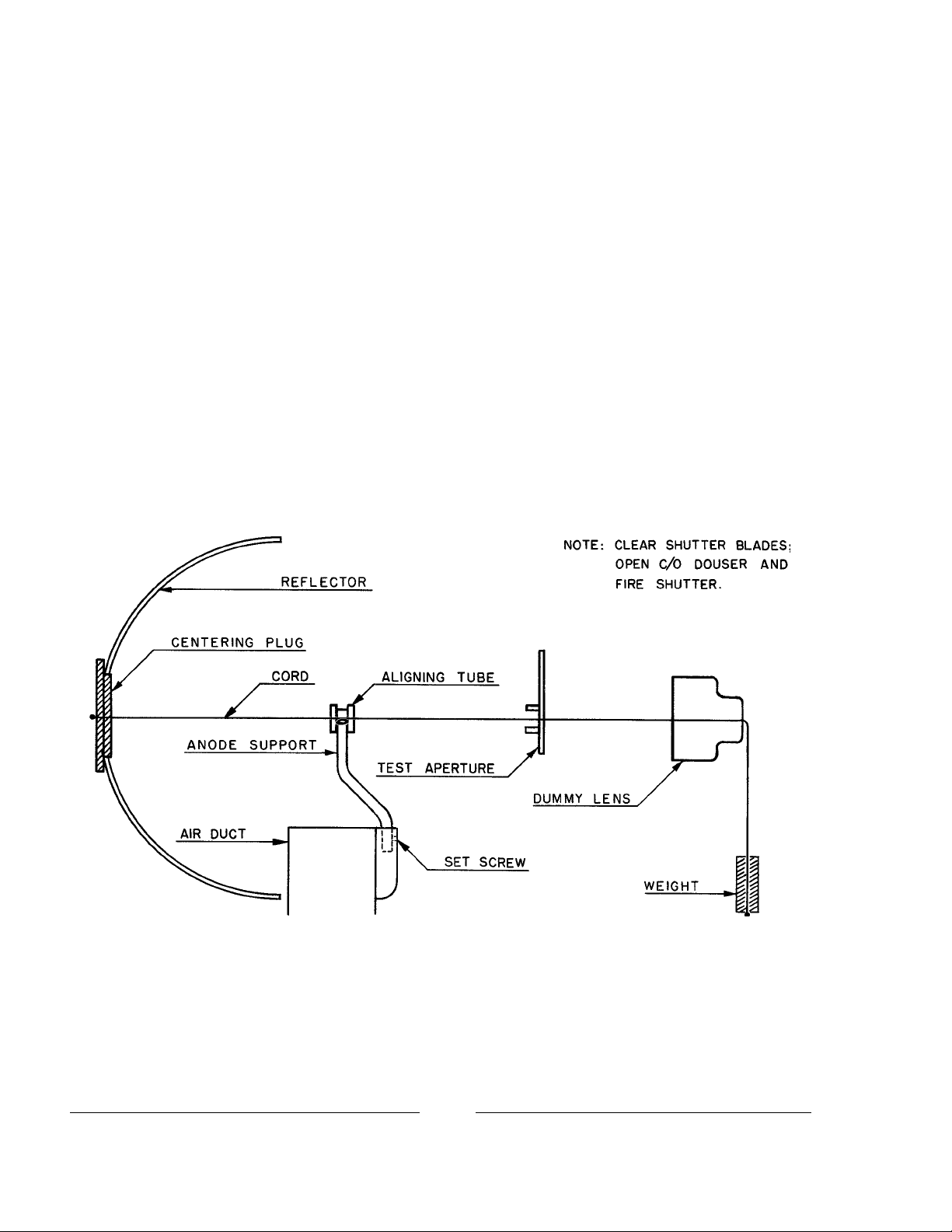
MECHANICAL LAMPHOUSE ALIGNMENT
ONE ALIGNING KIT consisting of an aligning cord, aperture plate, dummy lens, and
centering plug is supplied with each lamphouse to provide an accurate and reliable method of optical
alignment of the lamphouse to the projector mechanism. Because of the relatively small arc produced
by the xenon bulb, good screen results can be obtained only by the careful use of this aligning kit.
PLACE THE LAMPHOUSE on the projection pedestal, making certain that it is centered between the ways. Open the side access door.
IF USING the optional Heat Filter, the filter holder bracket should be installed onto
the lamphouse before aligning the lamphouse to the projector. Do not insert the filter until the following aligning procedure has been completed.
POSITION THE LAMPHOUSE on the table so the center of the reflector measures as
near 34.5 inches from the projector aperture as the projector design will permit.
IN PREP ARATION for optical alignment, bolt the lamphouse temporarily to the pedestal table using the 5/16-18 cap screws shipped with the lamphouse accesssory kit.
U80/004
Page 7

INSERT THE CENTERING PLUG into the reflector opening, and secure the cord
behind it as illustrated. Place the aligning tube on the anode support yoke and run the cord through it.
Open the douser.
REMOVE THE PROJECTION LENS and pull the cord through the lens barrel. Pass
the cord through the dummy lens and tie the cord to an object of sufficient weight to hold the cord
taut. Position the test aperture as illustrated in the film trap of the projector. Close the film gate to
hold the test aperture in place.
MOST PROJECTOR BASES have adjustable lamphouse tables so the lamp can be
brought into optical alignment with the projector mechanism. If the lamphouse table is not adjustable,
use shims or washers at the front, rear, or at both ends of the lamphouse to obtain optical alignment to
the projector.
ALIGN THE LAMPHOUSE in relation to the projector so the cord passes through
the center of the hole in the test aperture, and the correct cord image is seen on the reflector. Set the
anode support yoke as illustrated and tighten the set screw in the air duct. DO NOT reposition the
reflector, as it is factory prealigned for maximum optical ef ficiency .
ONCE CORRECT ALIGNMENT is achieved, tighten the lamphouse mounting screws
to secure the lamphouse to the table. Remove the cord and associated fixtures and restore the operation of the fire shutter.
STORE THE ALIGNING KIT in a secure location in the projection booth. If the
Ultra 80 reflector is ever removed or replaced, it is necessary to repeat the entire cord alignment
procedure, Likewise, if a different type or wattage bulb is used in a subsequent relampment, it may be
necessary to re-align the anode yoke to position it for the optical center of the replacement bulb.
U80/005
Page 8
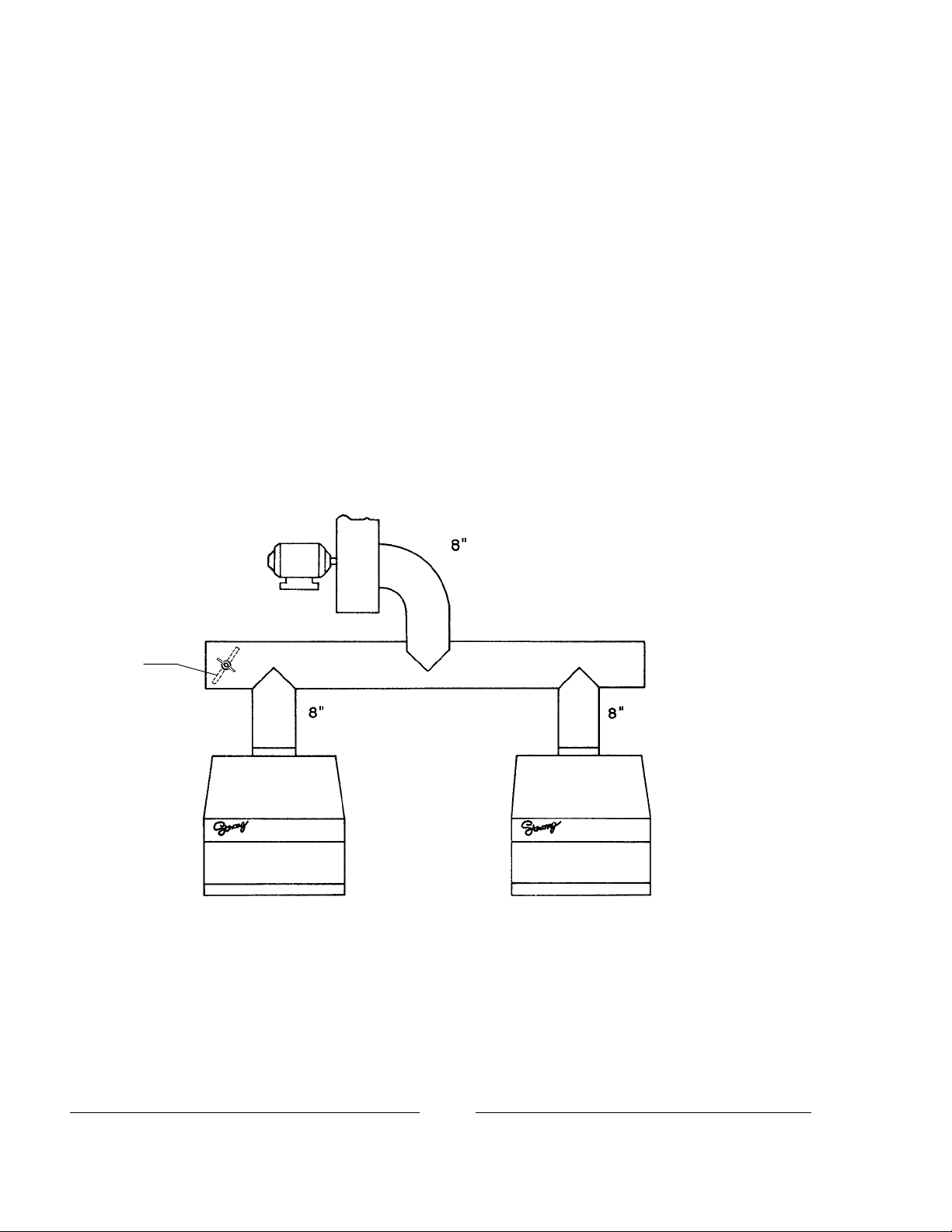
EXHAUST SYSTEM INSTALLATION
THE EXHAUST DUCT of the Ultra 80 is designed to fit an eight inch diameter
exhaust duct. This size ducting, either rigid or heat-resistant flexible, must be used throughout the
complete exhaust system. The exhaust system must be vented to outside air, and installed in such a
manner as to eliminate any possibility of downdraft or rain dripping into the lamphouse.
THE EXHAUST F AN must be capable of removing 700 cubic feet per minute (cfm) of
air, as measured at the exhaust outlet of the lamphouse. If more than one lamphouse is connected to
a common exhaust system, each individual lamphouse must meet the 700 cfm requirement.
IF THE EXHAUST AIR FLOW must be restricted for any reason, install bypasses
rather then dampers in the exhaust line.
Bypass
(as req’d.)
(700 cfm) (700 cfm)
CHECK EACH LAMPHOUSE for correct exhaust air flow . Insufficient exhaust draft
can severely shorten bulb life, and no credit will be allowed bulbs damaged in this manner . Inadequate
exhaust may also cause possible injury to personnel by overheating the lamphouse enclosure.
THE XENON BULBS approved for use in the Ultra 80 are designated as ozone free.
See “BULB INSTALLATION AND OPERATION.”
U80/006
Page 9
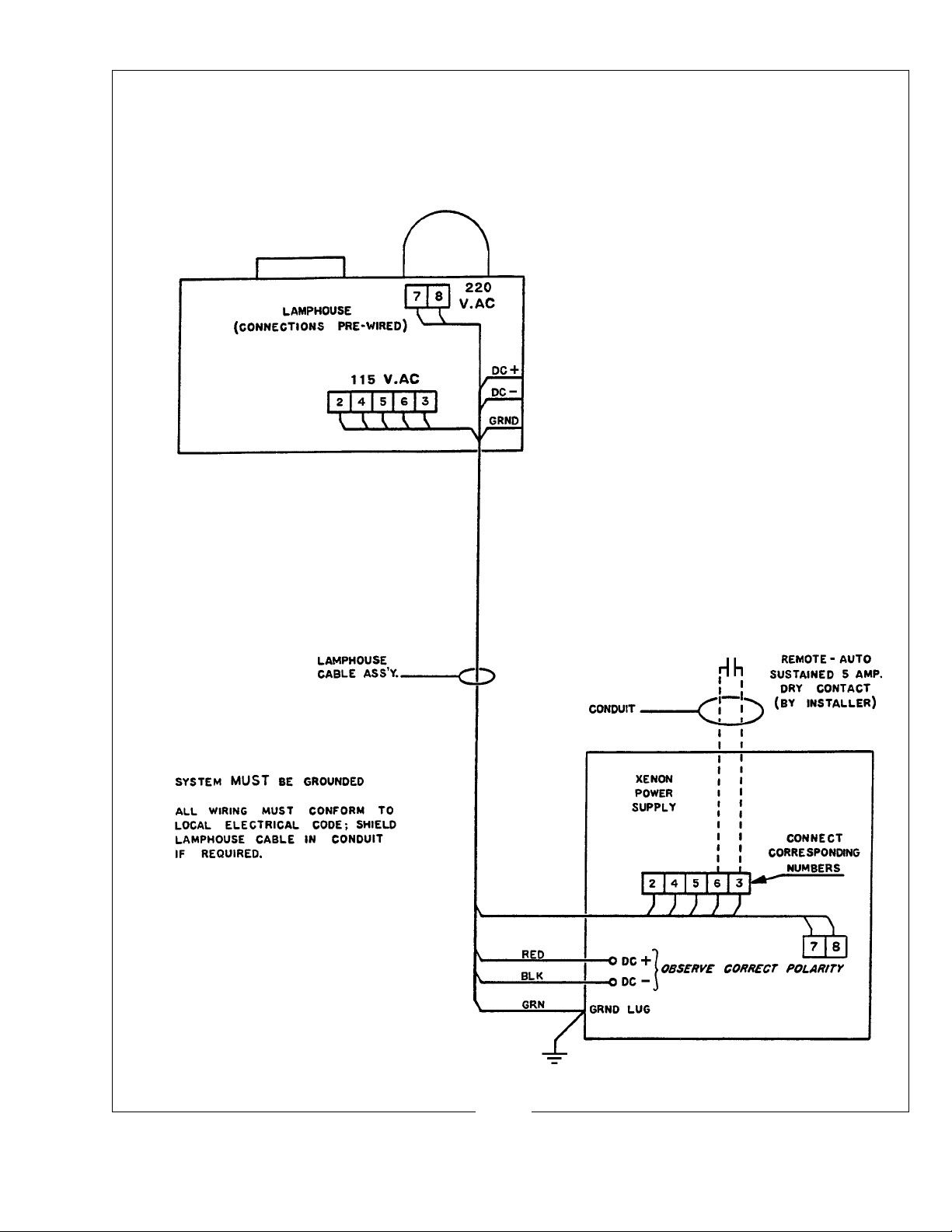
LAMPHOUSE - POWER SUPPLY INTERCONNECTION DIAGRAM
Ultra 80
U80/007
Page 10

WIRING INST ALLATION
THE LAMPHOUSE LEADS must be connected to the xenon power supply as illustrated on the Installation Diagram.
CONNECT THE TWO HEAVY FIBREGLASS INSULATED LEADS to the DC
outputs in the power supply. Observe correct polarity; red to positive (+), black to negative (-).
Tighten connections securely to prevent overheating. Leads 2, 4, 5, and 6 provide the 115 V.AC
control circuit between the lamphouse and power supply, and wires 7 & 8 (220 V.AC) power the
lamphouse blower. Connect them to their corresponding numbered terminals on the barrier strip in
the power supply cabinet.
COLOR CODE:
Brown #2
Red #3
Orange #4
Blue #5
Yellow #6
Grey #7
Black #8
BECAUSE OF HIGH VOLTAGES impressed during the ignition cycle, the xenon
lamphouse must be grounded. Connect the ground lead in the cable assembly (#8 AWG green) to the
terminal lug in the power supply cabinet. Make certain that the power supply is connected to an
adequate earth ground.
IF AUTOMATED or remote lamphouse switching is desired, it is generally more convenient to make such connections to the power supply barrier strip (3 & 6) as illustrated. See the
“AUTOMATION SYSTEMS” section following for detailed instructions.
ALL LEADS may be run in conduit or greenfield if desired, or if required by local
code. This may also be necessary as shielding to prevent electrical interference in the theatre sound
system.
IT IS RECOMMENDED to establish a routine of periodically checking all electrical
connections for tightness. Loose connections, particularly in the DC circuit, are subject to hazardous
overheating.
U80/008
Page 11
SAFETY PROCEDURES
THE XENON BULB is highly pressurized. When ignited, the normal operating temperature
of the bulb increases the pressure to a level at which the bulb may explode if not handled in strict accordance to
the manufacturer’s operating instructions. The bulb is stable at room temperature, but may still explode if
dropped or otherwise mishandled.
REFER bulb replacement and service to QUALIFIED PERSONNEL with adequate protective
clothing (face shield, clean cotton gloves, welder’s jacket). For routine lamphouse service, observe the following rules:
1. Allow the bulb to cool to room temperature before opening the lamphouse. Put on protective clothing
described above.
2. De-energize the xenon power supply at the AC source before opening the lamphouse compartment.
3. When possible, encase the bulb in its protective cover when cleaning or servicing the lamphouse inte-
rior. The bulb, when outside the lamphouse, must be encased in the cover.
4. Clean the bulb after it has cooled to room temperature. Do not touch the quartz envelope of the bulb;
fingerprints will burn in and create hot spots which may shorten bulb life. If fingermarks are made,
they should be carefully removed with methyl alcohol and cotton prior to bulb operation.
5. Never view an ignited bulb directly. BLINDNESS OR PERMANENT EYE DAMAGE MAY BE
INCURRED.
6. Use only xenon bulbs designated as OZONE FREE. When possible, vent the lamphouse exhaust to
outside atmosphere.
7. Maintain the lamphouse blower in good operating condition. Keep the blower inlet clean for unre-
stricted air flow .
8. To insure maximum bulb life, operate the lamphouse blower and the exhaust system for at least ten
minutes after extinguishing the bulb.
9. If returning a bulb for warranty adjustment, pack it in its original shipping container. Complete and
return all required warranty information.
10. Dispose of expired bulbs that are beyond warranty in the following manner: Wrap the bulb tightly in
several layers of canvas or heavy cloth. Place it on a hard surface and shatter the envelope with a sharp
hammer blow . DO NOT place an unshattered bulb in an ordinary refuse container.
11. DO NOT PERMIT UNAUTHORIZED PERSONNEL TO PERFORM OR A TTEMPT ANY PHASE
OF XENON BULB HANDLING OR SERVICE.
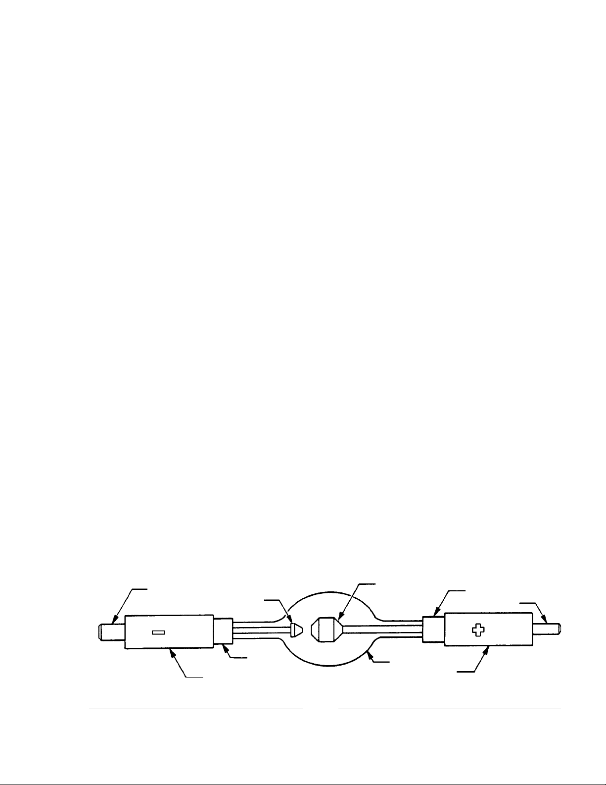
Cathode Pin
Cathode
Seal
Cathode End Cap
U80/009
Anode
Envelope
Anode End Cap
Seal
Anode Pin
Page 12
BULB INSTALLATION AND OPERATION
OBSERVE ALL SAFETY PROCEDURES. Bulb installation and replacement must
be performed by QUALIFIED PERSONNEL with protective clothing and face shield.
THE XENON BULB requires no adapters to mount in the Ultra 80. All bulb mounting fixtures and electrical connections are designed for use with the designated xenon bulb (7000 watt
for 40001; 10,000 watt for 40002). A silastic rubber tube is supplied with each lamp to permit insulating the bulb anode lead from the lamphouse base or other grounded metal components.
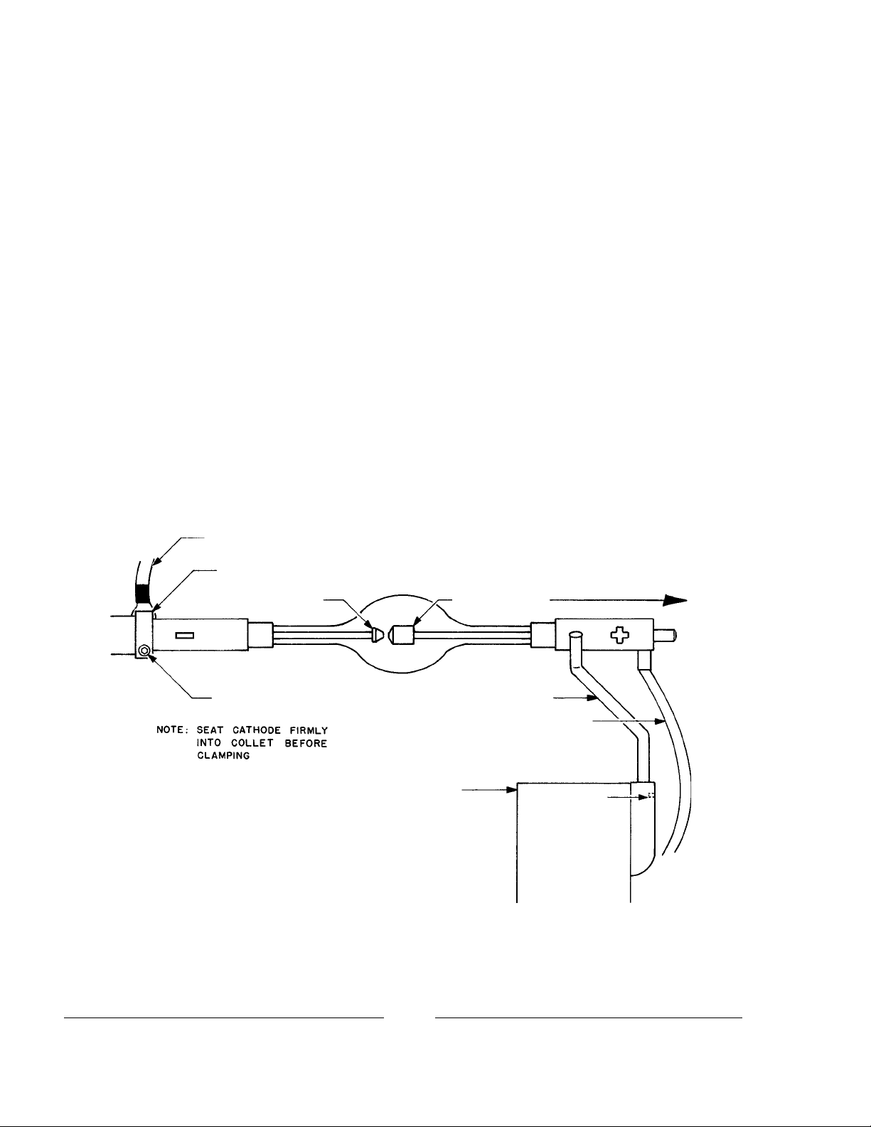
INSERT THE CATHODE (-) end of the bulb through the hole in the center of the
reflector. Seat the cathode pin into the cathode support collet as far as possible to permit full focus
travel of the bulb. Rest the anode (+) stem in the front support yoke and dress the anode lead directly
in front of the air duct. Securely tighten the socket head screw in the cathode clamp, taking care not
to apply any mechanical strain to the bulb vessel. Remove the hexnut, washer, and lockwasher from
the anode binding post in front of the reflector. Connect the anode lead to the binding post and tighten
securely .
Igniter Lead
Cathode Clamp
Cathode
Clamping Screw
Anode
Front Bulb Support Yoke
Bulb Anode Lead
Air Duct Casting
TOWARD
SCREEN
Set Screw
OBSER VE CORRECT POLARITY
REMOVE THE PLASTIC PROTECTIVE COVER (when applicable) from the bulb.
Close and secure the lamphouse door. Turn on the exhaust system. Place the MODE switch in the
“MAN.” position and close the douser.
U80/010
Page 13

TURN ON THE MAIN LINE SWITCH to energize the xenon power supply. The
POWER light on the lamphouse instrument panel will glow, the blower will start, and the air vane
switch will close to permit lamp operation. The lamphouse blower will operate continuously until the
main line switch to the power supply is opened.
PLACE THE LAMP SWITCH in the “ON” position and the bulb will ignite. Allow
the current to stabilize, and check the lamphouse ammeter. Set the power supply as required to supply
120-150 amperes to the 7000 watt bulb, or 150-180 amperes to the 10,000 watt bulb; DO NOT
exceed maximum rated current.
IF IGNITION does not occur, or the high voltage ignition pulse is not apparent, press
the emergency ignition switch located under the plug button on the top of the lamphouse. Do not hold
for more than one second; release immediately on bulb ignition. See the TROUBLESHOOTING
section following in this manual.
THE SMALL PUSHBUTTON SWITCH located directly above the ammeter may be
pressed while the lamp is operating to convert the meter reading to indicate the DC voltage at the arc.
This permits immediate calculation of the power at which the lamp is operating. Holding this switch
in at the ignition pulse will briefly display the “no load” voltage applied to the bulb for ignition.
REMOVE THE REAR COVER PANEL (two pull type knobs) to expose the bulb
position adjustment controls.
THE THUMB SCREWS on either side of the focusing control lock the horizontal and
vertical adjustment mechanism in position.
REMOVE THE PROJECTION LENS, start the projector, and open the douser. Do
not operate the lamp without the projector running.
TURN THE CENTER FOCUSING SECTION of the bulb position control until the
smallest black spot obtainable is focused on the projection screen. It may be best to run this adjustment both directions to permit positive identification of the spot. The position of the spot may be to
the right, left, top or bottom of the screen, and not necessarily in the center.
U80/011
Page 14

LOOSEN the two thumb
screws, one on either side of the focusing section, just enough to permit manual movement
of the complete assembly . The bulb adjustment
control will now move about these two thumb
screws, and as this control is shifted, the smooth
Support Y oke
Shadow
Anode
Shadow
Reflector
Hole
shadow of the electrode can be seen extending
beyond the projected hole in the reflector . The
electrode shadow must be centered inside the
projected hole of the reflector .
Projection Lens
removed
MOVE THIS CONTROL SECTION around the two thumb screws until the black
spot is as round as possible to project. It may be necessary to again adjust the focus control to define
a sharp spot. After the black spot is as even as possible to project, tighten the two thumb screws to
lock the adjustment section. This adjustment has now centered the projected image of the electrode
shadow and the hole in the reflector on the aperture and screen.
REPLACE THE PROJECTION LENS and rotate the focus adjustment until the
desired light distribution is projected to the screen. A void running the projector in this manner for an
extended period of time without frequently closing the lamphouse douser . W ithout film, the heat from
the xenon bulb can damage the projection lens.
THIS ADJUSTMENT should not be disturbed until it is necessary to replace or rotate
the xenon bulb. Then, only the bulb adjustments outlined above may have to be repeated; do not
disturb or adjust the optical alignment of the lamphouse on the projector table.
REPLACE THE REAR COVER PANEL over the bulb adjustment control mechanism. Press plungers into grommets to secure.
BECAUSE OF MANUF ACTURING TOLERANCES on the xenon bulb, and normal
aging, it may necessary to operate one lamp of a two-machine installation at slightly higher or lower
current to obtain equal light balance on the screen. This is done by adjusting the output of the xenon
power supply .
TO EXTINGUISH the arc, place the LAMP switch in the “OFF” position. The lamphouse blower will continue to operate until the main switch in the AC power line to the xenon power
supply is opened.
TO PROLONG BULB LIFE, leave the blower and exhaust fan operate for at least ten
minutes after turning off the lamp. Allow the bulb to cool to room temperature before opening the
lamphouse access door for any reason.
A PERMANENT MAGNET is mounted behind the reflector to stabilize the arc
between the electrodes of the ignited bulb. The magnet requires no adjustment. If the magnet is
removed for any reason, it must be replaced with the SOUTH pole nearest the lamphouse access door.
The south pole is stamped “S” and marked with paint.
U80/012
Page 15

AUTOMATION SYSTEMS
TO INTERCONNECT the lamp to an automation system, two #16 AWG wires (not
supplied by Strong) must be installed as illustrated on the Interconnection Diagram. These wires must
be shielded to prevent interference in the theatre sound system.
NOTE: Lamp ignition in “AUTO” mode is effected by a sustained dry contact closure between
terminals 3 and 6. DO NOT apply voltage to these terminals. Refer to instructions furnished by the
manufacturer of the automation controller.
TO OPERATE with an automation system, place the MODE switch in the “AUTO”
position, and the LAMP switch to “ON.” When the xenon power supply is energized, the lamphouse
POWER light will glow, and the blower will operate. The bulb will not ignite until provided a dry
contact between 3 and 6 by the automation controller . Opening this contact will extinguish the bulb,
and allow the POWER light and the blower to continue to operate.
IN THE EVENT of an automation failure, manual control of the lamp can be restored
by placing the MODE switch in “MAN.” and switching “ON or “OFF” with the LAMP switch.
U80/013
Page 16

MAINTENANCE
THE ULTRA 80 LAMPHOUSE requires very little maintenance to keep it in good
working order . Cleanliness is the most important element.
THE REFLECTOR should be cleaned periodically with a soft, clean, lint free cloth to
remove any dust from the reflecting surface. If excessively soiled, use of a mild commercial glass
®
cleaner (Windex
or equivalent) is acceptable; USE NO ABRASIVE CLEANERS.
THE XENON BULB should be checked occasionally for the presence of foreign material on the envelope. Any dirt or other foreign material should be removed promptly. Use only
alcohol and a clean cloth to clean the bulb; rinse with distilled water and dry carefully . DO NOT touch
the bulb with bare fingers, and observe all safety procedures when working around the bulb.
THE INSIDE OF THE LAMPHOUSE and the impeller blades of the blower should be
cleaned periodically, depending on the dust conditions at each installation. The grilles over the air
intakes can be removed for cleaning; do not allow dirt or dust to build up on the grille or in the fan
impeller.
THE XENON LAMPHOUSE does not require any lubrication other than at the
blower(s). Use two or three drops of non-detergent motor oil every four to six months. The oil holes
are located on the motor portion of the blower. Removing the blower covers will not affect the
mounting of the blowers.
CHECK ALL ELECTRICAL CONNECTIONS periodically for tightness, especially
the DC leads at the xenon bulb and at the shunt and igniter. Inspect crimped joints for oxidation, and
remake the connection if oxidized.
FOLLOW THE RECOMMENDATIONS of the xenon bulb manufacturer regarding
periodic bulb rotation. It is a general practice to rotate the bulb 180° at 50% of warranty life. After
rotating a bulb, increase current to the maximum allowable level, and operate the bulb at this elevated
level for three or four shows.
ALWAYS allow the lamphouse blower and the exhaust system to operate for at least
ten minutes after extinguishing the bulb. Failure to do so will shorten bulb life.
U80/014
Page 17

B2 Side Blower used on 10 kW Type 40002 only
5 & 6: 115 V.AC to Po wer Supply Contactor (K1)
3 & 6: 5 Amp. Dry Contact f or Remote-A uto Switching
(by Installer)
U80/015
Page 18

SCHEMATIC DIAGRAM
Parts List
Ref
Desig. Part No. Description
B1 40220 Bulb Seal Blower , 220 V.AC, 50/60 Hz.
B2 47944 Reflector Blower Assembly 115 V.AC, 50/60 Hz.
* B2 Used with 10,000 Watt Type 40002 ONLY *
C1,2 76132 Capacitor, .005 µf, 600 WVDC
C3 76133 Capacitor, .01 µf, 400 WVDC
C4A,B 76323 Capacitor, 1.0-1.0 µf, 600 WVDC
C5 81947 Capacitor, .05 µf, 500 WVDC
C6,7 88263 Capacitor, .05 µf, 600 WVDC
C8 39956 Capacitor, .05 µf, 2000 WVDC
DS1 78984 POWER Indicator Light, 1 15 V.AC
DS2 - Xenon Bulb, 7000 Watt; Order Hanovia XH7000HS
DS2 - Xenon Bulb, 10,000 Watt; Order Hanovia XH10000V(H)
E1 40987 Binding Post, DC Positive (+)
- 40131 Fibre Insulator
F1 40203 Fuse, 3 Amp. Slo-Blo
- 39199 Fuse Holder
M1 40971 Elapsed Time Meter, 60 Hz.
- 40963 Elapsed Time Meter, 50 Hz.
M2 40923 Ammeter , 0 - 300 Amp.
PCB 40913 Igniter Printed Circuit Board Assembly (Standard)
- 40984 Igniter PC Board (with High Reactance Power Supply)
R1 81247 Shunt, 50 mV.
R2 71283 Resistor, 90.9k Ohm, ¼ Watt, 1%
S1 80168 Door Interlock Switch
S2 81275 LAMP Switch, “ON - OFF”
S3 81276 MODE Switch, “AUTO - MAN.”
S4 39955 Air V ane Switch Assembly (Exhaust)
S5 85109 Air Vane Switch (Intake)
S6 72275 Voltage Test Switch
- 39999A Igniter Assembly
- 40902 Interconnect Cable, Lamphouse to Power Supply
Specify Equipment T ype and Serial Number when ordering replacement parts.
U80/016
Page 19

PRINCIPLE OF IGNITER OPERA TION
THE IGNITER is energized through the 115 V.AC control circuit when the LAMP
“ON-OFF” switch (S2) is depressed and all interlocks and air flow switches are closed.
CAUTION: Do not use the Emergency Ignition switch (S102) in the igniter until it is
determined that the polarity of the xenon bulb is correct. Use of the S102 switch bypasses the polarity
sensing diode (CR201) on the igniter printed circuit board; if polarity is not correct, the bulb will be
seriously damaged or destroyed. No credit is allowed on bulbs damaged by reversed polarity .
THE IGNITER supplies a high RF voltage pulse to the bulb, together with the high
“No Load” DC voltage from the xenon power supply, to ignite the xenon bulb. After the arc is
sustained, the AC circuit in the igniter is interrupted by the opening of K201 relay contacts on the
signal of the timer circuit on the PC board. The DC output of the xenon power supply is automatically
lowered to the power level required to maintain the arc. The DC power to the bulb is dependent upon
the bulb characteristics and the setting of the output of the xenon power supply .
DC VOLTAGE is applied to the printed circuit board from the xenon power supply,
energizing the 12 V.DC coil and closing the contacts of K201 relay , completing the AC circuit through
the igniter to the T102 high voltage (10 kV.) transformer. High voltage boost capacitor C107 is
charged to a voltage sufficient to cause breakdown across the E101 spark gap. Approximately 35 kV.
is supplied to the xenon bulb for ignition.
S101 is the igniter cover interlock switch and S102 is the Emergency Ignition switch,
which is a bypass for the K201 relay contacts and CR201 polarity sensing diode on the PC board.
Components C101, 102, and 103 function as RF bypass capacitors on the igniter . The C108 capacitor
serves as a coupling capacitor to the current coil.
THE PC BOARD operates on DC voltage from the xenon power supply. Capacitor
C201 across the positive #10 and negative #15 is an RF suppression capacitor. Resistor R201 and
zener diodes VR201 and 202 drop the DC voltage to 12 volts for the K201 relay coil. CR201 is the
polarity sensing diode. C204 is a polarized capacitor used for arc suppression at the K201 relay coil,
and CR202 functions as a transient protection diode.
THE FOLLOWING COMPONENTS are parts of the timing circuit on the PC board:
Timer chip U201, resistors R202, 203, and the polarized capacitor C203. The C203 capacitor functions as the timing control, and CR203 serves as the “ON” time control diode. C202 is the control
voltage isolation capacitor .
U80/017
Page 20

U80/018
IGNITER SCHEMATIC
Ref.
Desig. Part No. Description
C107 39110 Capacitor, 2400 pf, 20 kV.DC
C108 39110 Capacitor, 2400 pf, 20 kV.DC
E101 39923 Spark Gap Assembly
S101 80168 Cover Interlock Switch
S102 80168 Emergency Ignite Switch
T101 39937 High Voltage Transformer
- 39998 Case & Coil, Potted Assembly
Page 21

U80/019
Ref.
Desig. Part No. Description
C201 88263 Capacitor, .05 µf, 600 WVDC
C202 79127 Capacitor, .01 µf, 600 WVDC
C203 39156 Capacitor, 15 µf, 30/35 WVDC
C204 88249 Capacitor, .1 µf, 600 WVDC
CR201 85112 Diode, 2.5 A. 1000 PRV
CR202 85112 Diode, 2.5 A. 1000 PRV
CR203 85112 Diode, 2.5 A. 1000 PRV
K201 39154 Relay, P&B R10-E1-W2S800
- 39160 Relay Socket
- 39161 Relay Hold-Down Spring
R201 39157 Resistor, 1k Ohm, 12 Watt
R202 39158 Resistor, 100k Ohm, ½ Watt
IGNITER PRINTED CIRCUIT BOARD SCHEMATIC
WIRE MARKERS
A = 10
B = 15
C = 17
D = 38
Ref.
Desig. Part No. Description
R203 39159 Resistor, 200k Ohm, ½ Watt
U201 72185 Timer IC, Motorola MC11455P1
- 39164 IC Socket, (6) Pin
VR201 39211 Zener Diode, 1N5377A (40913*)
VR201 81519 Zener Diode, 1N5361 (40984*)
VR202 39162 Zener Diode, 1N4742
- 39145 PC Board (less Components)
* 40913 PCB Assembly, Standard
* 40984 PCB Assembly (Older Models using
High Reactance Power Supply)
Assembly Number written on Component Side of PCB.
Page 22

TROUBLE CHART
NOTE: When working inside the lamphouse, enclose the xenon bulb in its protective
covering and/or wear protective clothing and face shield. Do not touch the quartz envelope of the
bulb with bare fingers.
ALLOW THE LAMPHOUSE to cool, with all blowers operating, for at least (20)
minutes before opening the access door.
Normal Operation:
When the switch in the main AC supply line to the xenon power supply is placed in the “ON”
position, with the door interlock switch closed, the lamphouse POWER light will glow and the lamphouse blower(s) will operate. The top lamphouse blower will close the S4 air vane switch, and the
correct operation of the exhaust system will close the S5 air vane switch. These conditions complete
the circuit to the S2 LAMP “ON-OFF” switch.
Place the lamphouse MODE switch S3 in the “MAN.” position. When the lamphouse LAMP
switch S2 is in the “ON” position, the elapsed time meter will operate and the AC circuit (5 - 6) to the
xenon power supply will energize the circuitry necessary to supply DC voltage to the igniter and bulb.
There will be an audible high voltage arc ping at the spark gap in the igniter and at the xenon
bulb. The bulb should ignite immediately after one or two of these high voltage pulses, and the lamp
current will adjust to the sustaining level set at the xenon power supply. An aged or “warm” xenon
bulb may require repeated ignition cycles.
Troubleshooting:
If the xenon bulb does not ignite, observe the following operational sequences for assistance in
locating and isolating the trouble area.
When operating with a xenon power supply equipped with the red indicator light, and the light
is “ON,” the AC circuit in the power supply is trouble free up to the terminal block (L1, L2, L3) in the
power supply .
The blower(s) the lamphouse and the POWER light on the instrument panel should operate. If
this does not occur, the trouble is in either the door interlock switch, a blower motor, the indicator
lamp, a loose connection, a broken #2, #4, #7 or #8 lead, or a defective stepdown transformer in the
xenon power supply . The Ultra 80 has an in-line fuse in the 220 volt blower circuit; check the fuse and
replace if blown. Do not overfuse; use 3 A. slow blow .
U80/020
Page 23

CAUTION: To prevent bulb ignition when checking the AC control circuit, remove the #6
lead running from the igniter at the terminal post on the lamphouse base pan. Tape the exposed lead
to prevent shorting out the circuit.
Check the 115 V.AC control circuit in the lamphouse at the door switch, then the control leads
at terminals #9 and #12 (the “side” blower on 40002 lamp). The door interlock switch must be
manually actuated to energize this circuit.
The air flow from the top blower will move the actuating lever on switch S4, and the exhaust
draft should close switch S5. With the MODE switch in the “MAN.” position, and the LAMP switch
in the “ON” position, the elapsed time meter should start to indicate elapsed time. If this meter does
not operate, check for continuity at the LAMP and MODE switches. Check continuity of the air flow
switches; both should read 0 Ohms between “NO” and “COM” when actuated. A defective elapsed
time meter will not prevent bulb ignition. Replace lead #6.
With the LAMP switch in the “ON” position, a distinct high voltage arc ping at the igniter
spark gap should be heard, and a flash from the xenon bulb should be visible through the ammeter, as
DC voltage is applied to the bulb electrodes.
If the high voltage ping or the flash at the ammeter is not apparent, check the DC “No Load”
voltage between the lamphouse and power supply . Again disconnect lead #6 running from the igniter
at the terminal strip on the lamphouse base. Tape the end of the disconnected lead and close and
secure the lamphouse door.
Press the switch above the ammeter, and the meter will indicate the “No Load” DC voltage
supplied to the lamphouse when the LAMP switch is turned “ON.” This voltage will vary between
different types of power supplies. See your power supply manual for its correct “No Load” rating.
The standard 40913 igniter printed board in the Ultra 80 is designed for use with a Strong
switching power supply with high DC “No Load” voltage. Consult the factory if using an older high
reactance xenon power supply with normally lower DC “No Load” voltage.
If the correct voltage for the power supply being used is not indicated on the meter, the problem is in the lamphouse/power supply interconnecting cable, or in the power supply . See the troubleshooting guide in the power supply manual for additional instructions and tests. Replace lead #6 on
the terminal strip on the lamphouse base.
If the high voltage arc is audible at the lamphouse, and the bulb does not flash, replace the bulb
and attempt ignition with the new bulb.
Using the new bulb, if the high voltage arc is audible at the lamphouse, the flash of the bulb is
visible in the ammeter, and ignition is not sustained, the problem is in the power supply.
If the high voltage arc is not audible or the flash of the bulb visible, the trouble is in the igniter
or the igniter printed circuit board.
U80/021
Page 24

ULTRA 80 TROUBLESHOOTING
Bulb fails to ignite.
1. AC power not on to lamphouse. If 115 V.AC not read at 2 & 4, see power supply manual.
Check for loose 220 volt connection at 7 & 8.
2. Door interlock switch S1 open. Close and secure lamphouse access door. Tighten all three
screws; lock door and install security screw .
3. Faulty door interlock switch. Check for 115 V.AC at 9 & 12; replace switch if defective.
4. Air vane switch S4 not closing. Check for unobstructed operation; clean if required. Check
continuity between “NO” and “COM”; replace if defective.
5. Faulty S2 “ON-OFF” switch. Check for voltage at 3 & 5; check for loose wiring. Replace if
defective.
6. Automation fault. Override automation by switching MODE to “MAN.” and placing LAMP
switch in “ON.” See Automation Controller manual.
Bulb fails to ignite; ping audible, bulb flash visible.
1. Inadequate DC output from xenon power supply. Set power supply output to correct range
required for bulb wattage.
2. Faulty or expired xenon bulb. Replace as required.
Bulb fails to ignite; ping audible, no bulb flash.
1. Faulty xenon bulb. Check for cracked electrodes or darkened envelope. Replace if defective.
2. Ignition pulse shorting to ground. Inspect DC leads for burned insulation; dress leads away
from grounded metal components.
No high voltage ping audible; MODE switch in “MAN.” and LAMP switch in “ON.”
1. Loss of AC control voltage. Check xenon power supply for tripped circuit breaker or open
thermal switch. See power supply manual.
2. Little or no DC “No Load” voltage. Measure DC “No Load” voltage at 10 & 15. See power
supply manual.
3. Faulty igniter printed circuit board. If bulb ignites by pressing Emergency Ignition switch,
replace printed circuit board.
4. Faulty igniter. Check for 115 V.AC at 5 & 6; adequate DC “No Load” at 10 & 15. Replace
igniter if defective.
Bulb goes out during operation.
1. Xenon power supply overheated; thermal switch open. Check power supply blower(s), air
inlets and outlets unobstructed. See power supply manual.
U80/022
Page 25

Bulb goes out during operation (con’d.)
2. Lamphouse blower B1 failed or obstructed. Clean dust and dirt from blower inlet grille.
Check for 220 V.AC at 7 & 8; replace blower if defective.
3. Blower fuse F1 blown. Replace if defective (3 A. Slo-Blo).
4. Lamphouse air vane switch S4 or S5 faulty. Check for vane motion and switch continuity
(“NO” to “COM”); adjust or replace as required.
5. Backdraft from exhaust system. Check exhaust system installation; increase exhaust draft as
required.
6. Intermittent relay closure in automation controller. Override automation by switching MODE
to “MAN.” and check automation controller.
7 Phase loss or brown-out in xenon power supply AC source. Check AC input.
Power supply does not energize when actuated.
1. S1 door interlock switch, B1 blower, S4 air vane switch, S2 power switch, S3 MODE switch.
Check for correct voltage at each station; replace defective component.
2. Automation fault. Check for continuity between 3 & 6. See Automation Controller manual.
Use “MAN.” mode to override.
ALSO SEE POWER SUPPLY TROUBLESHOOTING
Noise in theatre sound as bulb ignites.
1. Faulty RF suppression capacitor(s). Remove and test C1, C2, C3, C4A or C4B. Replace if
defective.
2. Lamphouse, power supply, or sound system not properly grounded. Connect to adequate
earth ground.
3. Leads between lamphouse and automation contact not shielded. Shield leads in conduit.
Excessive light flicker .
1. Faulty or aged bulb. Check for cracked or sagging electrodes; replace if defective.
2. Arc stabilization magnet missing or reversed. Replace or correct (SOUTH pole toward access
door).
3. Excessive ripple in DC output. See power supply manual.
4. Projector shutter mistimed. See projector manual.
Reduced light output.
1. Normal bulb aging. Increase output current. DO NOT EXCEED MAXIMUM CURRENT
SPECIFIED BY BULB MANUFACTURER.
2. Bulb leakage. Check for high current and low voltage; discoloration of bulb envelope. Replace if defective.
3. Soiled reflector. Clean using commercial glass cleaner . USE NO ABRASIVES.
4. Soiled projection lens or port glass. Clean as required.
U80/023
Page 26

Extremely long duration between ignition pulses.
1. Low DC “No Load” from xenon power supply. Check “No Load” voltage; see power supply
manual.
2. Defective spark gap E101. A “Ping” sound is normal; excessive “Hissing” is abnormal. Replace if defective.
3. Low AC voltage to lamphouse. Check for 115 V.AC at 2 & 4; if below 95 volts, check
stepdown transformer in xenon power supply . See power supply manual.
4. Faulty K201 relay or U201 timer chip on igniter printed circuit board. Remove and test PCB;
replace if defective.
Igniter continues to fire after bulb ignites.
1. Faulty igniter printed circuit board. If defective, replace IMMEDIATELY to prevent bulb
damage.
U80/024
Page 27
U80/025
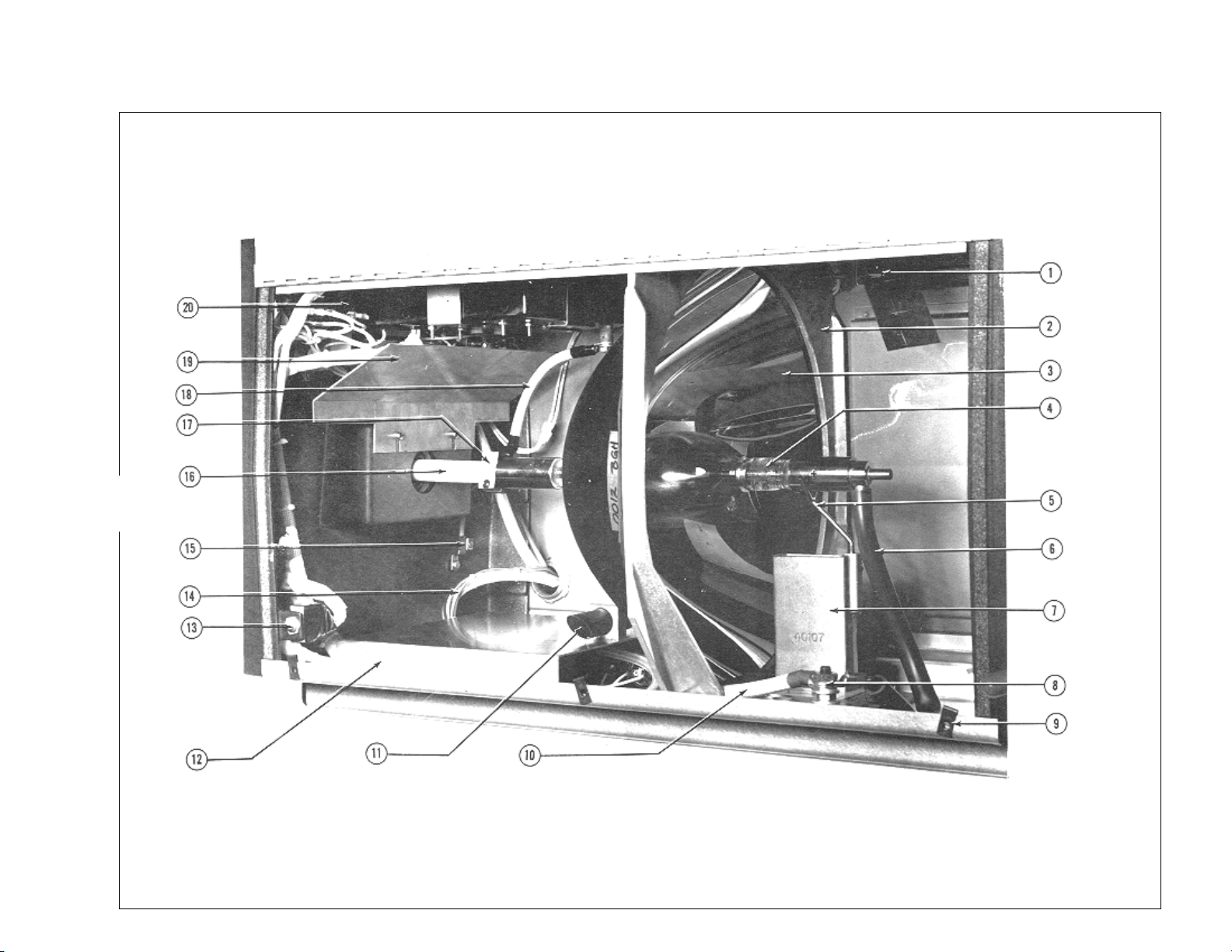
FIGURE 1
Page 28

FIGURE 1
Parts List
Item Part No. Description
1 40917 * Top Cover & Door Welded Assembly
2 40994 Front Casting Assembly (with Items 3, 4, 5)
- 40106 Front Casting (only)
- 40137 Front Heat Shield
3 81148 Douser Plate
- 81432 Shoulder Screw
- 81234 Bumper Stop
- 81187 Torsion Spring
- 00721 Set Screw, 10-32 x 3/8" Hex Head
4 45150A Handle Grip, Plastic
5 40115 Douser Shaft
6 01736-1 Tamperproof Screw, 10-32 x 1/2" Holt Head
7 48930 Arc Viewing Port Assembly
8 40917 * Top Cover & Door Welded Assembly (See Item 1)
- 71248 Cam Lock & Keys (not shown)
9 40105 Rear Casting
10 39139 Magnetic Door Catch
11 40220 Bulb Seal Blower , 220 V.AC, 50/60 Hz. (B1)
- 31-40002 Plug, Blower Motor
- 11-40019 Power Receptacle, Blower Motor
12 40920 Grille, Blower Cover (2 req’d.)
40194 Blower Cover
NOT SHOWN
- 40989 Instrument Panel Assembly (See Fig. 2 for components)
- 01423 Panel Mounting Screw, 10-32 x 5/16" Pan Head
- 39122 Ingiter Cover Access Plate
- 01304 Cover Mounting Screw, 8-32 x 5/16" Pan Head
- 00891A Lockwasher, #8
- 57275 Plug Button, Emergency Ignition Switch
- 40918 * Off-Operator Side Cover & Heat Shield W elded Assembly, 7 kW
(less Reflector Blower)
- 40903 * Off-Operator Side Panel Assembly , 10 kW (with Reflector Blower)
- 01345 Panel Mounting Screw, 10-32 x 1/2" Pan Head
- 00885 Lockwasher, #10
- 47944 Reflector Blower Assembly 115 V.AC, 50/60 Hz. (B2)
- 31-40002 Twistlock Plug
- 11-40019 Twistlock Receptacle
* Do not dismount Top Cover and Side Cover simultaneously; optical alignment may be affected.
U80/026
Page 29
U80/027
FIGURE 2
Page 30

FIGURE 2
Parts List
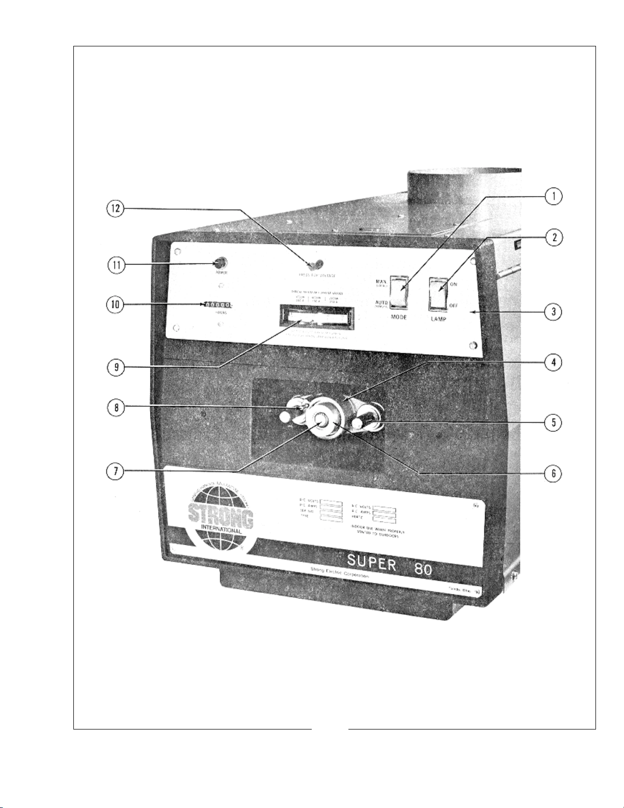
Item Part No. Description
1 81276 MODE Switch (S3)
2 81275 LAMP Switch (S2)
3 40102 Plate, Instrument Panel (less Components)
- 01423 Screw, 10-32 x 5/16" Pan Head
4 65116 Casting, Bulb Adjustment Mechanism
- 65197 Fender Washer, Inner
5 37985 Thumb Screw
- 15010 Compression Spring
- 65150 Fender Washer, Outer
6 65959 Focus Screw & Bearing Assembly
7 40930 Bulb Collet, 7 kW (See Figure 3, Item 16)
7 40901 Bulb Collet, 10 kW (See Figure 3, Item 16)
- 21-48027 Collet Retaining Ring, “C” Clip
8 65153 Thumb Screw, Focus Lock
- 65154 Nylon Locking Ball
9 40923 Ammeter (M2)
10 40971 Elapsed Time Meter (M1) 60 Hz.
- 40963 Elapsed Time Meter (M1) 50 Hz.
Mounting Hardware supplied with Meter
11 78984 POWER Light (DS1)
12 72275 Voltage Test Switch (S6)
- 71283 Resistor (R2)
NOT SHOWN
- 40119 Cover Plate, Bulb Adjustment Controls
- 65166 Plunger, Black Plastic
- 65167 Grommet, Black Plastic
U80/028
Page 31
U80/029
FIGURE 3
Page 32

FIGURE 3
Parts List
Item Part No. Description
1 39955 Exhaust Air V ane Switch Assembly (S4)
2 40202 Reflector Bulkhead Casting
- 40142 Bulkhead Tie Rod
- 00805 Hex Nut, 1/4-20
3 23754 Reflector, 15" Dichroic Coated, Flanged
4 - Xenon Bulb, 10,000 Watt; Order Hanovia XH10000V(H)
4 - Xenon Bulb, 7000 Watt; Order Hanovia XH7000HS
5 40999 Bulb Support Yoke
- 00781 Set Screw, 8-32 x 1/4" Allen Head
6 81348 Insulator, Anode Lead (NOT USED in Ultra 80)
7 40107 Air Duct Casting
- 401 16 Air Duct Insulator Plate
- 01796 Screw, 5/16-18 x 3/4" Nylon
8 40987 Binding Post Assembly (E1)
- 40130 Block, Brown Phenolic
- 00642 Screw, 3/8-16 x 1-1/2" Flat Head
- 00809 Jam Nut, 3/8-16
- 00854 Flatwasher, 3/8"
- 40131 Fibre Insulator
- 00492 Screw, 1/4-20 x 3/4" Flat Head
- 00876 Split Lockwasher, 1/4"
- 00805 Hexnut, 1/4-20
10 40981 Anode Cable Assembly (R1 to E1)
1 1 M15315 Arc Stabilization Magnet
- 81137 Magnet Clamp
- 00781 Set Screw, 8-32 x 1/4" Allen Head
- 01710 Screw, 8-32 x 1/4" Hex Head
12 40120 Dust Cover
- 01742 Screw, 8-32 x 1/4" Pan Head
- 00891A Lockwasher, #8
13 80168 Door Interlock Switch (S1)
14 40902 Lamphouse/Power Supply Interconnect Cable Assembly
- 81143 Cable Connector, 90°
15 81274 Ground Lug
- 01423 Screw, 10-32 x 5/16" Pan Head
- 00891A Lockwasher, #8
U80/030
Page 33

FIGURE 3 Parts List (con’d.)
Item Part No. Description
16 24432 Bulb Support Collet, 5 kW*
16 40930 Bulb Support Collet, 7 kW
16 40901 Bulb Support Collet, 10 kW
17 24430 Collet Contact Clamp, 5 kW*
- 41-51213 Clamping Screw, 10-32 x 1" Socket Head
- 00685 Screw, 1/4-20 x 3/8" Hex Head
17 40111 Collet Contact Clamp, 7 & 10 kW
- 01532 Clamping Screw, 8-32 x 7/8" Socket Head
- 00685 Screw, 1/4-20 x 3/8" Hex Head
18 40979 Contact Clamp & Igniter Lead Assembly
19 40164 Light Baffle
- 01566 Screw, 10-24 x 5/16" Pan Head
- 00885 Lockwasher, #10
20 39999A Igniter Assembly (See Figure 5A)
* for 5 kW Osram with 18mm Cathode Pin. Other 5 kW bulbs
emulate 4 kW and 4.5 kW models. Consult bulb supplier .
NOT SHOWN
- 85109 Intake Air V ane Switch, Bulb Seal Blower (S5)
- 65158 Switch Mounting Bracket
U80/031
Page 34

FIGURE 4
U80/032
Page 35

FIGURE 4
Parts List
Item Part No. Description
1 - Not Used in Ultra 80; See Figure 1, Item 11
2 40136 Capacitor Clamp
- 01382 Screw, 8-32 x 3/16" Pan Head
- 00891A Lockwasher, #8
3 76323 Capacitor (C4A, C4B) 2 req’d.
4 40981 Anode Cable Assembly (R1 to E1)
5 40983 RF Capacitor Assembly (C1, C2, C3)
- 39153 Nylon Standoff
6 76133 Capacitor (C3)
7 76132 Capacitor (C1, C2)
8 40913 Igniter Printed Circuit Board Assembly
- 40984 Igniter PC Board (with High Reactance Power Supply)
- 39153 Nylon Standoff
- 39154 Relay (See PCB Schematic)
9 40974 Capacitor (C8)
10 40103 Barrier Strip, (14) T erminal
- 40138 Insulated Marker Strip
- 01799 Screw, 8-32 x 9/16", Round Head
- 00891A Lockwasher, #8
11 80168 Door Interlock Switch (S1)
12 81247 Shunt (R1)
- 01312 Screw, 8-32 x 1/2" Pan Head
- 00891A Lockwasher, #8
13 40973 RF Bypass Capacitor Assembly (C6, C7)
14 39199 Fuse Holder
- 40203 Fuse (F1)
15 81274 Ground Lug
- 01423 Screw, 10-32 x 5/16" Pan Head
- 00885 Lockwasher, #10
16 40902 Lamphouse/Power Supply Interconnect Cable Assembly
- 81143 Cable Connector, 90°
17 40901 Bulb Support Collet, 10 kW (See Figure 3, Item 16)
18 85109 Air Vane Switch (S5) Mounted to Top Blower in Ultra 80
- 65158 Switch Mounting Bracket
19 40164 Light Baffle (See Figure 3, Item 19)
U80/033
Page 36

FIGURE 5
U80/034
Page 37

FIGURE 5
Parts List
Item Part No. Description
- 39999A Igniter Assembly 115 V.AC, 50/60 Hz.
1 39260 Cover Interlock Switch (S101)
2 39113 Switch Bracket
- 00343 Screw, 10-32 x 1/4" Flat Head
3 39260 Emergency Ignition Switch (S102)
4 39110 High Voltage Capacitor (C107, C108)
- 00254 Screw, 8-32 x 1/4" Fillister Head
- 00891A Lockwasher, #8
- 39112 Capacitor Mounting Bracket
- 01752 Screw, 1/4-20 x 1" Hex Head Nylon
- 01754 Hex Nut, 1/4-20 Nylon
5 01742 Screw, 8-32 x 1/4" Pan Head
- 00981A Lockwasher, #8
6 39998 Case & Coil Potted Assembly
- 65353 DANGER Label
7 39201 * Spark Gap Body, Nylon
- 01567 Screw, 10-24 x 1/2" Pan Head
8 39107 * Contact Screw, Tungsten
- 39109 Terminal Tab (Order KT-74)
- 00831 Flatwasher, #10, Brass
- 00795 Hex Nut, 8-32
9 39937 High Voltage Transformer (T102)
- 01582 Flatwasher, #8
- 00795 Hex Nut, 8-32
10 39204 Transformer Spacer (4 req’d.)
* 39923 Spark Gap Assembly (Items 7 & 8, assembled and gapped)
NOT SHOWN
39101 Igniter Box Cover, Plastic
01305 Screw, 6-32 x 1/4" Pan Head
U80/035
Page 38

Page 39

 Loading...