

Page 1
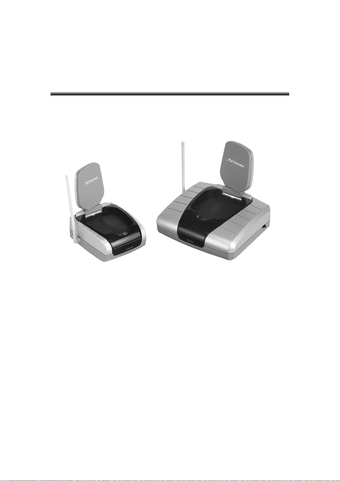
VIDEO SENDER
DOMÁCÍ PŘENAŠEČ AV SIGNÁLU
VIDEO LINK transmit / receive system provides a wireless connection between the
main source of Audio and Video equipment to another Audio and Video equipment. High
quality video and stereo audio can now be distributed without the need for complicated wiring.
One transmitter can feed multiple of receivers. The VIDEO LINK can also be used as
wireless link between a PC, Camera, and CATV.
Page 2
GETTING STARTED
SIGHTING
The proposed site for the transmitter should be near the main TV and VCR, free from
vibration, in an open space and protected from moisture and dampness.
The receiver should be located close to the second TV where you wish to view.
INSTALLATION
CONNECTING THE POWER
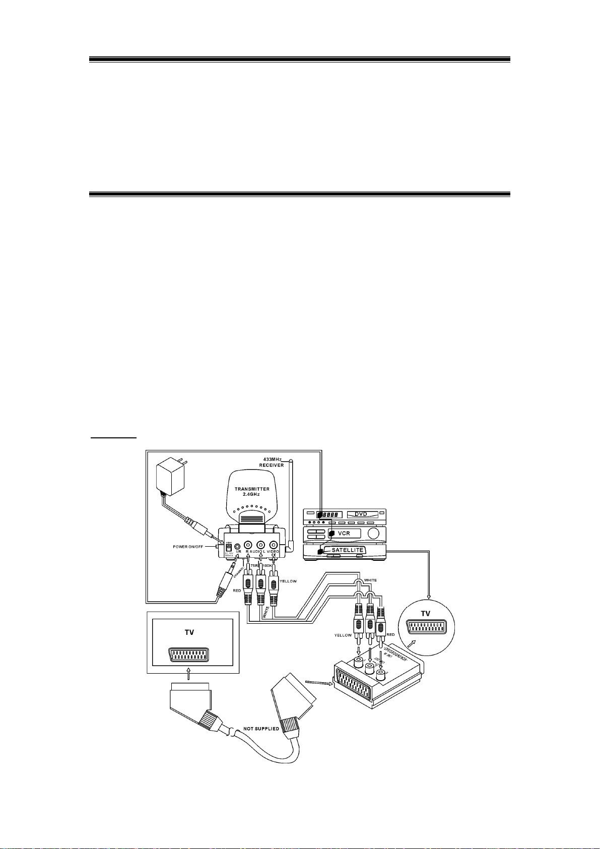
• Connect the transmitter and receiver up to the system as shown in the diagram below.
• Connect the AC top plug to a 230V 50Hz AC socket outlet.
• Ensure that the receiver is well ventilated.
• Do not place other equipment directly on top of the transmitter and receiver.
CONNECTING THE TRANSMITTER
Initially we recommend the transmitter, receiver and second TV be operated in the same
room so that the operation can be easily understood. When the system is working correctly
transfer the receiver and second TV to your required location. The connection of the
transmitter is as shown below:
Picture 1:
1
Page 3

INSTALLATION
Please follow the instructions below:
• Disconnect the source equipment scart lead from the TV
• Using the same scart lead, connect one side of the scart connector accessory provided
with the set to the TV.
• Connect the other side of the scart connector accessory to the source equipment.
• Connect the RCA (Red/white/yellow) lead of the scart connector to the RCA input
connectors on the Transmitter video link.
• Plug the Infra Red emitter into the I/R outputs on the transmitter.
• Run this lead so that the emitter can transmit to the sensor in the source equipment or be
able to reach all equipment’s to be controlled.
• Adjust the position of the emitter if it does not operate correctly.
• Study the equipment that you are trying to control to locate the equipment’s sensor.
• Ensure that the emitter is pointing at the sensor.
• When the operation has been proved the emitter can be secured with the self-adhesive
pad.
• Remove the protective paper and fix into position.
• Arrange the Plate aerial and the rod aerial upright and the flat surface pointing towards
the
receiver.
2
Page 4
INSTALLATION
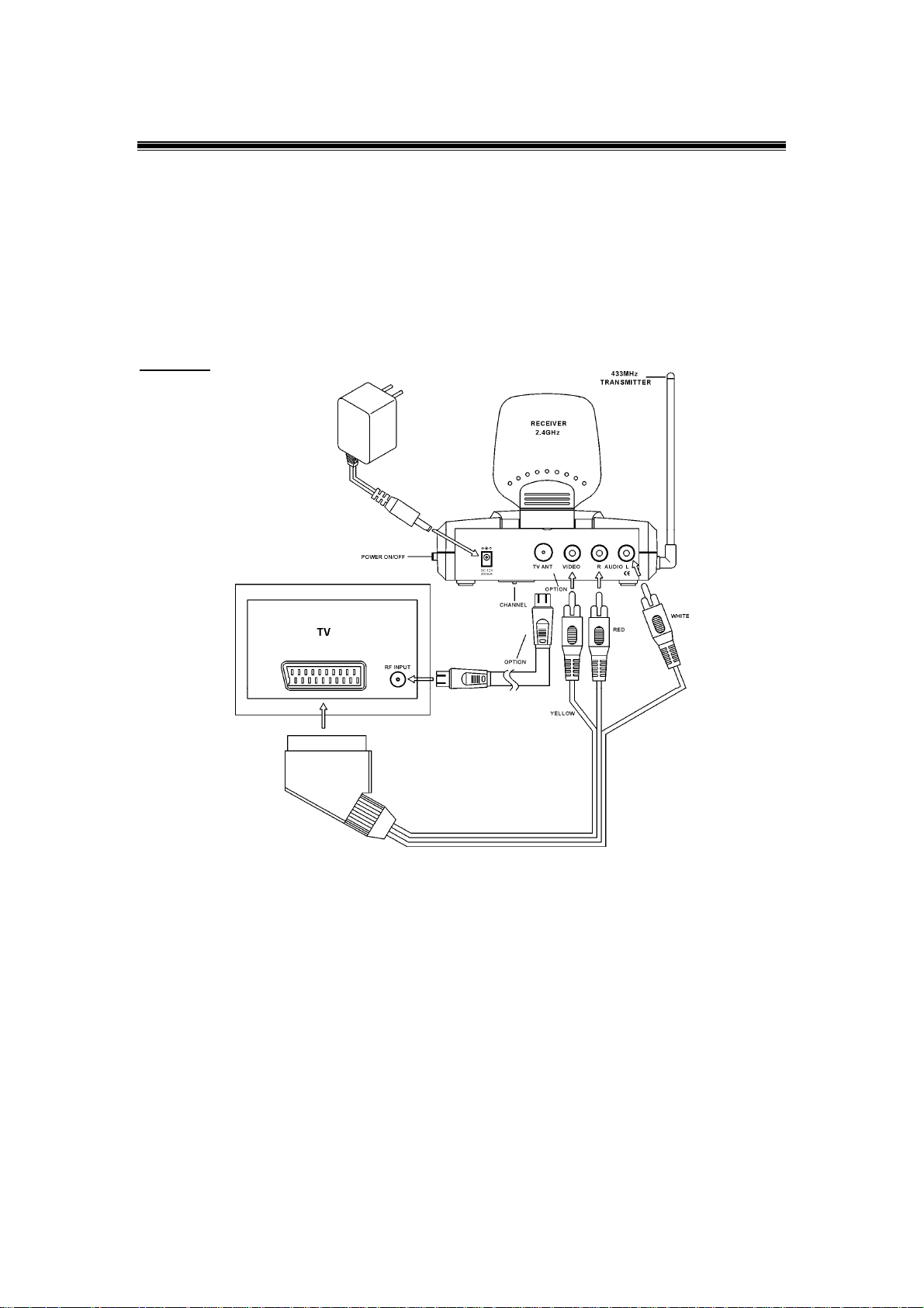
CONNECTING THE RECEIVER
• Connect an RCA-scart lead or RF leads from the receiver to the second TV. As shown
below:
Picture 2:
• Arrange the Plate aerial and the rod aerial upright and the flat surface pointing towards
the
receiver.
• The installation is now complete.
3
Page 5
TESTING THE SYSTEM
• With the power connected press the standby button on each unit to switch them on.
• Play the source equipment that is connected to the transmitter.
• The transmitted video and audio should now be seen on the second TV.
• Adjust the plate aerials to understand their operation.
• The receiver and transmitter are pre-set to channel 1 at power on.
• If there is interference seen when the equipment is in its final location try changing to
another channel.
• The line of sight range is approximately 50 metres but this can be reduced considerably
by
the effect of walls etc.
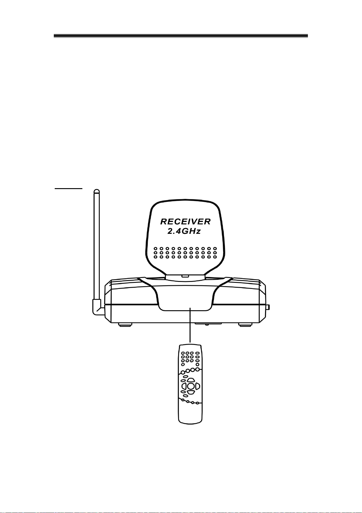
Picture 3:
Point the VCR remote handset at the receiver and check that this controls the VCR.
4
Page 6

TECHANICAL DATA
TRANSMITTER
◊ PAL/SECAM FM modulated @ 2.45 GHz transmitter.
◊ Operational voltage: 12 V DC (by adaptor 220-240 V)
◊ Multi-channel (selectable) : CH1: 2.410 GHz/ CH2: 2.431GHz/ CH3: 2.452 GHz, CH4: 2.473 GHz
◊ 3 RCA input.
◊ Video level: 1V PP , 75 Ohm. Switch selectable.
◊ Audio level: automatic correction. 0.2V to 2V IN
◊ Directional aerial
◊ FM stereo sound
◊ On/off with indicator
◊ Infra red link in the IR version: 433MHz
◊ Size W 80 x D 100 x H 39 MM
◊ Scart connector accessory for simple connection.
◊ CE certified
RECEIVER
◊ Compatible 2.45 GHz receiver for the above transmitter
◊ Multi-channel (selectable): CH1: 2.410 GHz/ CH2: 2.431GHz/ CH3: 2.452 GHz, CH4: 2.473 GHz
◊ On/off with indicator
◊ UHF modulator
◊ Size W 121 x D 125 x H 39 MM
◊ Directional aerial
◊ FM stereo sound
◊ CE certified
5
 Loading...