

STRONG HD STB User’s Manual
IMPORTANT SAFETY INFORMATION
All safety and operating Instructions should be read before the product is operated.
All warnings on the product and in the operating instructions should be adhered to.
Do not use this apparatus near water.
Clean only with a dry cloth. Do not use liquid cleaners or aerosol cleaning products.
Do not block any of the ventilation openings.
Do not install near any heat sources.
Do not defeat the safety purpose of the polarized or grounding-type plug.
Protect the power cord from being walked on or pinched particularly at plugs, convenience
receptacles, and the point where they exit from the apparatus.
Only use attachments/accessories specified by the manufacturer.
Use only with a cart, stand, tripod, bracket, or table specified by the manufacturer, or sold with
the apparatus.
Unplug this apparatus during lightning storms or when unused for long periods of time.
Refer all servicing to qualified service personnel.
The SRT 5400 should be installed 10cm away from a wall to allow for the Power Switch and
Power Lead on the back panel
To reduce the risk of electric shock, do not remove cover (or back).
No user serviceable parts inside. Refer servicing to qualified
service personnel.
This symbol indicates dangerous voltage inside the product that
presents a risk of electric shock or personal injury.
This symbol indicates important instructions accompanying the
product.
1

TABLE OF CONTENTS
1 Important Safety Information
2 Table of Contents
3 Introduction
4 Front Panel view
5 ~ 6 Rear Panel View
7 ~ 8 Remote Control Buttons
9 ~ 16 Installation
17 ~ 23 DTV Specific Menu Operations
24 ~ 30 Configuration Universal remote Control Unit
STRONG HD STB User’s Manual
31 Menu Map
32 ~ 33 Technical Specifications
34 ~ 36 Rear Panel Connector Specifications
2

STRONG HD STB User’s Manual
INTRODUCTION
Thank you for purchasing this Strong Digital Terrestrial Television Receiver.
This product has been manufactured in accordance with strict Quality Control Procedures and is
fully compliant with Australian DVB-T digital television standards.
Your new Receiver will enable you to experience superior picture and sound quality, widescreen
images, extra channels plus a variety of new features.
UNIT CONTENTS
Remote control unit
Two batteries (size AA)
Video and stereo audio RCA cable
YPbPr(RGB color) cable
FEATURES
1080i / 720p / 576p / 576i Video Formats
Format Change by Remote Control
Simultaneous HD & SD
Component - YPbPr
DVI-I
RGBHV / RGB Component - VGA
Composite - CVBS
S-Video – Y/C
Dolby Digital Optical & Coaxial
16:9 Fullscreen, 4:3 Letterbox & Fullscreen
Picture in Picture
Zoom Mode by Remote Control Hot Key
Auto & Manual Channel Search
Favourite Channel List
Electronic Program Guide
Preprogrammed STB/TV Remote Control
Captions
Teletext
Super Sensitive Tuner
RS–232C Port for Software Upgrade
DVB/T Compliant, COFDM Demodulation
DVB, MPEG – 2 Compliant,
3
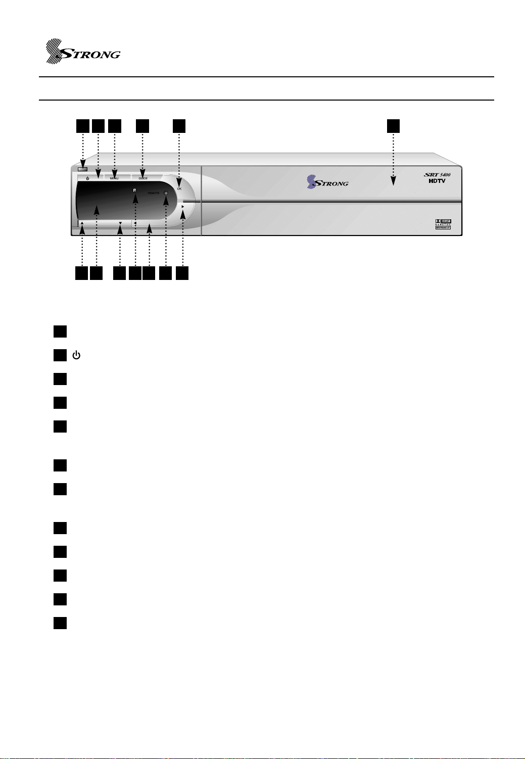
FRONT PANEL VIEW
STRONG HD STB User’s Manual
1 2 3 4 5
6 87 9 10
1
Standby LED : Standby mode LED
2
: Turn on/off power.
3
MENU : To access the main menu or to go back upper level.
4
GUIDE : To view program information
1211
12
5
OK : Used to select item and complete numeric value entry or modify values in the menu
entry.
6
CH UP : Move cursor up from set up menu or channel up.
7
Digit LED display : This will display the current channel or certain programming functions
when using the menus.
8
CH DOWN : Move cursor down from set up menu or channel down.
9
IR : Infrared remote control sensor.
10
VOL UP : Volume ‘up’ adjustment
11
LAMP : Light on power on mode.
12
VOL DOWN : Volume ‘down’ adjustment
Front Panel buttons and menu allow for control of the SRT 5400 without the remote control unit
except the function of FAVORITES, INFO and some advanced features.
4
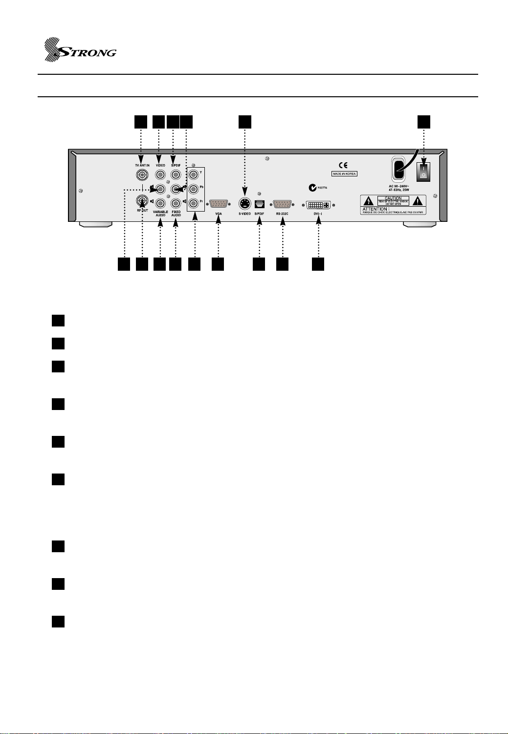
REAR PANEL VIEW
STRONG HD STB User’s Manual
6 831 11
4 52 7 9
1
TV ANT IN : RF input for connecting the STB to a terrestrial antenna using a coaxial cable.
2
RF Out : To Connect to another set top box or recording device e. g. VCR / TV.
3
VIDEO (YELLOW) : Composite video jack for connecting the STB to your television using
14131210
15
standard RCA cable.
4
Variable Audio - L (WHITE) : Left RCA audio jack for connecting the STB to your television
audio input using standard RCA cable.
5
Variable Audio - R (RED) : Right RCA audio jack for connecting the STB to your television
audio input using standard RCA cable.
6
S/PDIF COAXIAL : Digital audio output for connecting the STB to your AV receiver or Dolby
Digital decoder using digital coaxial cable. Set this output to AC-3 Dolby
Digital or Stereo PCM in the STB setup menu or by the SAP button on
the remote control.
7
FIXED Audio - R (RED) : Right RCA audio jack for connecting the STB to your VCR audio
input using standard RCA cable.
8
FIXED Audio - L (WHITE) : Left RCA audio jack for connecting the STB to your VCR audio
input using standard RCA cable.
9
YPbPr OUT(Component) : Component RCA video jacks for connecting the STB to your
television using coaxial cables.
5

STRONG HD STB User’s Manual
10
VGA OUT : RGB/VGA component output for connecting the STB to a television using a
VGA cable.
11
S-VIDEO : S-video jacks for connecting the STB to an S-Video compatible VCR or
television.
12
S/PDIF OPTICAL : Digital audio output for connecting the STB to your AV receiver or Dolby
Digital decoder using optical cable. Set this output to AC-3 Dolby Digital
or Stereo PCM in the STB setup menu or by the SAP button on the
remote control
13
RS-232C : RS232C serial connection for future upgrades of the STB.
14
DVI-I OUT : Digital video signal and RGB component output for connecting the STB to a
television using a DVI cable.
NOTE : The YPbPr, VGA and DVI-I outputs carry the same R/G/B signals using
different physical connectors. Choose only one – do not use both at the same
time.
15
AC POWER INLET : Inlet to connect the STB to a standard power wall outlet.
6
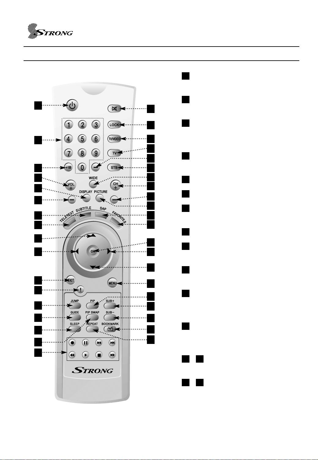
REMOTE CONTROL BUTTONS
1
3
5
13
11
15
17
19
21
23
2
4
6
7
8
9
10
14
16
12
18
20
24
22
STRONG HD STB User’s Manual
1
POWER : Switch the STB between
operation and standby mode.
2
MUTE : Turns the audio on and off.
Line L, R output is not affected.
3
0 ~ 9 : Used to select channel
directly or set setup values like
password.
4
LOCK : Used to turn on/off –
Channel Lock.
5
+100 : Not Used
6
TV/VIDEO : Not Used
7
TV : Switch remote control unit to
television control mode.
8
dash button (-) : Not Used
9
STB : Switch remote control unit to
STB control mode.
27
28
31
33
35
32
37
25
26
29
30
34
36
38
10
WIDE : Aspect Ratio selection of
16:9 and 4:3
11
DISPLAY : Used to select
1080i/720p/576p/576i video mode
directly.
12
PICTURE : Zoom mode selection
including preview mode on picture
view (not for Composite or S-Video)
1513
/ VOL + / VOL- : Used to volume
up and down.
1614
/ CH +/CH- : Service up to down
through the available services.
7

STRONG HD STB User’s Manual
17
SUBTITLE : To turn Closed Captions on/off
18
SAP : Select Audio Program Dolby Digital and PCM
19
TELETEXT : Teletext
20
FAVORITES : Used to tune to next available Favorite program.
2521
/ UP / DOWN : Move cursor up / down from set up menu.
2322
/ LEFT/RIGHT : To navigate in program guide. Right button can be used as ENTER
button.
24
OK : To select item and complete numeric value entry or modify values in the menu entry.
26
MENU : Used to invoke set up menu or to go back upper level.
27
EXIT : To exit menu
28
! : To invoke Information Panel.
29
PIP : Turn on / off PIP function. (HD Outputs Only – not available when using S-Video and
CVBS Composite)
3430
/ SUB +/- : Channel change for PIP
31
JUMP : Not used
32
PIP SWAP : Switch main program and sub program.
33
GUIDE : To view program guide.
35
SLEEP : Display the sleep time. At the sleep time, enter standby mode automatically.
36
BOOKMARK : Setting the Favorite channel
37
OPTION KEYS : Not used
38
REPEAT : Not used
8
STRONG HD STB User’s Manual
INSTALLATION
CONNECTING THE SRT 5400 TO YOUR TELEVISION
For connection of the SRT 5400 there are number of alternatives depending what is your
preference and the connection types on your TV.
Please connect by either of the following methods:
A. B. C. For High Definition VIDEO Signal
D. E. For Standard Definition VIDEO Signal
F. Mandatory for Antenna connection
(Audio connections are explained separately following these video connection explanation
alternatives)
Refer to Page 5 & 6 for the Connector Reference Numbers listed below.
A. Connector 9 : YPbPr (Component – For HD)
Using supplied Green / Blue / Red RCA Lead
Connector 9 YPbPr Connect to the Green/Blue/Red RCA
(
Component
)(
Component)Connectors of your TV
B. Connector 10 : VGA (For PC RGB signal- For HD)
You will need to purchase this lead separately.
Connector 10 VGA Connect to the VGA connector of your TV
C. Connector 14: DVI-I (For HD)
You will need to purchase this lead separately
Connector 14 DVI Connect to the DVI connector of your TV
D. Connector 1
You will need to purchase this lead separately
Connector 11 S Video (Y/C) Connect to the S-Video connector of your TV
1: S-Video (Y/C) (For SD)
9
STRONG HD STB User’s Manual
E. CVBS (Composite – For SD) via the supplied Y
ellow / White / Red RCA Lead
For this Standard Definition Composite Video connection, Audio is also included, this will
be PCM Stereo.
Connector 3
(Yellow)
Connector 4
(White)
Connector 5
(Red)
VIDEO
AUDIO Left
AUDIO Right
RCA cinch
RCA cinch
RCA cinch
Connect to Video (Yellow) RCA
of your TV
Connect to audio (White) RCA
of your TV
Connect to audio (Red) RCA of
your TV
If you require Dolby Digital Audio Output (through you’re Dolby Digital Decoder Amplifier)
please refer to : DOLBY DIGITAL AUDIO (page 11)
F. Connecting the Antenna
Connect TV Antenna to Connector 1 (Aerial)
Connector 1 Aerial IEC169-2
Input from Antenna to Receiver
female
Audio Connections
PCM Stereo – V
ariable : Using supplied Yellow / White / Red RCA Lead
(Other than when connecting for CVBS Composite, the Yellow RCA will not be required to be
connected)
Connector 4
(White)
AUDIO Left
RCA cinch
Connector 5
(Red)
AUDIO Right
PCM Stereo – Fixed Using supplied Y
RCA cinch
ellow / White / Red RCA Lead
Connect to audio RCA input
(White) of your TV
Connect to audio RCA input
(Red) of your TV
Refer Page 22: 2ndAudio Volume Mode
(Other than when connecting for CVBS Composite, the Yellow RCA will not be required to be
connected)
Connector 7
(Red)
Connector 8
(White)
AUDIO Right
AUDIO Left
RCA cinch
RCA cinch
Connect to audio RCA input
(White) of your TV
Connect to audio RCA input
(Red) of your TV
10
STRONG HD STB User’s Manual
Dolby Digital Audio
If you have a Dolby Digital Decoder Amplifier, you can connect to the amplifier by S/PDIF
i.e either by Connector 6: Coaxial Cable or Connector 12: Optical Cable. (Both leads
need to be purchased separately). This connection will provide for Dolby Digital Output
when broadcast to your decoder amplifier
Connector 6 S/PDIF Coaxial Connect to the Coaxial input of your Amplifier
Connector 12 S/DIF Optical Connect to the Optical input of your Amplifier
To ‘Enable’ Dolby Digital to be heard when transmitted within the broadcast stream, you
will need to select Dolby Digital In the TV Set Up Menu or by the SAP button on the
remote control
Dolby Digital by Menu System
Press the Menu button (Page 7 No.26) on the remote control and a Main Menu Banner will
be viewed listing 7 topics.
Using Remote Control Up/Down Scoll Buttons, Scroll to Set Up
Push Remote Control OK Button (main centre button of Remote Control: Button 24)
Set Up banner will be viewed listing 9 topics
Scroll to Digital Audio and push OK button on the remote control
Digital Audio banner will be viewed with right hand banner listing Digital Audio and PCM
Scroll to Digital Audio and setting will be confirmed by a RED dot.
Push OK to confirm the setting
Push EXIT to return to normal TV broadcasts
Dolby Digital by SAP button of the Remote Control
Press the SAP button on the remote Control
Digital Audio banner will be viewed with right hand banner listing Digital Audio and PCM
Scroll to Digital Audio and setting will be confirmed by a RED dot.
Push OK to confirm the setting
Push EXIT to return to normal TV broadcasts
11

STRONG HD STB User’s Manual
Connect AC Power Cord
Connect the C power cable of the SRT 5400 to a standard AC outlet.
POWER ON & Full SCAN
Listed below is the procedure to automatically scan to lock in all available channels.
Prior to this procedure it important to note:
In the Menu system of the SRT 5400, the default VIDEO setting is COMPONENT.
However, if you have connected by either S-Video (Y/C) or CVBS Composite, or
Component, VIDEO source will still be recognized and you will not need to alter the video
setting in the Menu System after you have completed the Automatic Scan procedure.
If you require to connect by either VGA (RGB Monitor/RGB Component) or DVI, you will
need to firstly connect by any of the other 3 Video methods listed above otherwise on first
set up of Automatic Scan, VIDEO will not be recognized.
Once Automatic Scan has been completed, Video pictures will be available thus enabling
you to select and view the Menus’s to change to your Video setting of either VGA or DVI.
POWER ON the SRT 5400
Turn the SRT 5400 ON. There is an ON/OFF Switch on the rear panel of the Receiver.
(Located beside the main power cord of the receiver) The 7-segment LEDs will light
On the SRT 5400 Remote Control Press (Page 7 No. 1) to turn on the STB. The Blue
Power LED will turn off.
Setting the Television Input Source
Press the Power On of Television Remote Control unit to turn on the television. Allow the
television to warm up. Press TV/Video button of television remote control unit to select
external video input connected to the SRT 5400.
When Power is ON, you will view a Strong Image Banner on the TV Screen for a few
seconds and banner view will then change to Press Menu Banner. Your Receiver is now
ready to be scanned to lock in all of the Broadcast Frequencies in your area.
You will see Strong Image Banner on Component, RGB mode.
12

Automatic Scan Process
STRONG HD STB User’s Manual
Press the Menu button (Page 7 No.26) on the remote control and a Main Menu Banner
will be viewed listing 7 topics.
Using Remote Control Up/Down Scoll Buttons, Scroll to Set Up
Push Remote Control OK Button (main centre button of Remote Control:Button 24)
Set Up banner will be viewed listing 9 topics
13

STRONG HD STB User’s Manual
Scroll to Full Scan and push OK button Twice on the remote control
Channel Scanning will now commence and will take approximately one minute and will
lock in all available frequencies in your area.
Once Full Channel Scan is completed, Set up Banner will be viewed with TV broadcast in
top right corner
This Picture in Menu TV broadcast will remain in view for 10 seconds and unit will then
revert to Full TV Broadcast.
SELECTING VGA AND DVI VIDEO MODE
Press the Menu button (Page7 No.26) on the remote control and a Main Menu Banner
will appear listing 7 topics.
Using Remote Control Up/Down Scroll Buttons, Scroll to Set Up
Push Remote Control OK Button
Set Up banner will be viewed listing 9 topics
14

STRONG HD STB User’s Manual
Scroll to Display Type and push OK
Display Type banner will be viewed listing 4 Topics.
The current Video Setting will be highlighted by a Red Dot
Scroll to your selected setting of either DVI or RGB monitor or RGB component
Push OK button on the remote control and setting will be confirmed by Red Dot:
Important : On your TV Remote Control, select the corresponding television input mode
via the TV/Video button.
Selecting and Changing Channels
There are 2 methods to select and change channels
A. Press the required Numeric Button on the Remote Control (0-9).
Please Note : SRT5400 has default LCN – Logical Channel System
1 = Ten Network & Affiliates
2 = ABC
3 = SBS
7 = Seven Network & Affiliates
9 = Nine Network & Affiliates
B. Select and change channels by using the Up/Down channel
Buttons CH + (14) CH – (16)
Volume Control
To adjust Volume UP and DOWN, press the following buttons on the remote control:
Volume Increase : VOL Button + (13)
Volume Decrease : VOL Button – (15)
Important : The Volume Level is dependant on the volume level that you firstly set
your TV I.e. via your TV remote control volume setting.
olume Mute
V
within
Press Mute button (2) on the remote control
Press Mute button again to reactivate sound.
15

STRONG HD STB User’s Manual
Program list menu
Press MENU(page7 ,No26)on the remote control unit and TV PROGRAM select.
The Program list menu appears.
Using the (Page 7 No.21/25) arrows on the remote control unit, highlight the
channel you want to add to your favorite lst, and then press BOOKMARK button (Page 7
No.36) on the remote control unit.
The channel now added in your favorites list.
By pressing BOOKMARK button on the program with favorite flag at Program list menu,
you can remove program from favorite list.
Viewing Favorites
To view a program from the favorite program list do the following:
Press (Page 7 No. 20) on the remote control unit. The next favorite program
is selected.
By pressing button repeatedly, user can navigate favorite programs.
16

STRONG HD STB User’s Manual
DTV SPECIFIC MENU OPERATIONS
Information Panel
Pressing button(Page 7 No.28), this Information Panel becomes active. This bar displays
major-minor channel number; channel name, title, start time, end time, content advisory rating,
closed captioning indicator, and extended text descriptions for current / next event. To have
quick response, the bar displays initial information but update in a second when program
description information is detected. RF signal status is displayed together. Pressing button
again with Information Panel deactivates Information Panel.
Figure 1. Example of Information Panel
Information Panel displays different contents on Trick Playing operation and video, music play
back. On Trick Playing operation, Information Panel and Trick Playing value display are
displayed together. On video playback, Information Panel and playback progress value are
shown together. The Information Panel displays file name, event name, event description, time
information, duration, Dolby availability. On music playback, music title, bit rate, artist name,
time information, album, duration is shown.
17

STRONG HD STB User’s Manual
Program Guide
Figure 2. Example of Program Guide Page
This page is visible with button(Page 7 No.33) press. This page shows all the
information found from Information Panel as well as additional program schedules not just
current / next event related contents. User can scroll through multiple programs with
(Page 7 No.21/25) buttons and select a program to tune it. To navigate through
different time zone, (Page 7 No.22/23) buttons are used.
Main Menu
Press button(Page 7 No.26) to invoke main menu that has 5 section entries:
Program List, Program Guide, Service, Setup, and Directory. By using the
buttons (Page 7 No.24/25) to select and use (Page 7 No.24) button the to see sub-
menu page. Once a sub-menu has been chosen the particular page is displayed and the main
menu disappears. shows an main menu of STB. Selecting Directory entity switches the STB
into playback mode.
Figure 3. Main Menu
18

STRONG HD STB User’s Manual
PROGRAM GUIDE
Figure 4. Program Guide Page
Program list is shown Figure 4. It shows installed programs and allows manual entry deletion.
This page allows the user to decide which program in the known programs to display. By using
the buttons (Page 7 No.21/25) to navigate to see the particular program’s
information and then using the (Page 7 No.24) button to select, the user can choose
the desired program.
Favorite Program
Each program entry can be set as favorite by pressing (Page 7 No.36) button.
If user presses BOOKMARK button on favorite program, favorite program flag is reset to
normal program.
Channel Lock
Each program entry may be blocked by pressing LOCK(Page 7 No.4) button from program list
page. When user tunes to locked program later, password is asked to enter to proceed. If user
press LOCK button on channel locked program, password is asked again and channel lock
flag is cleared.(Default password code is 0000)
19

STRONG HD STB User’s Manual
Service Menu
Figure 5. Service Menu Page
Audio Track [English / Spanish / French / Portuguese / German / Italian / Korean]: Select
prefered audio language when multiple audio language is available.
Teletext Sub-menu: (Available for DVB model)
Turn off OSD : Remove menu page when no button-input is given before the specified
interval time-out.
Subtitle turn on/off.
Signal status : Checking signal status of current channel.
Set time : Local time offset is calculated from current time setup and broadcasted clock
information.
Sleep time set
Modify password : Use to change password.(Default password code is 0000)
Fatory Default : All setting reset.(Default password code is 0000)
20

STRONG HD STB User’s Manual
Setup Menu
Figure 6. Setup Page
The Setup page consists of 9 groups of configurations; Display mode, Display type, Display
aspect ratio, screen mode, Prologic, Digital audio, 2
scan. (Figure 6) shows set-up menu page entities.
nd
Audio volume mode, Manual scan and Full
Display mode : The video menu page allows user to choose the display resolution [576i,
576p, 720p, 1080i]
Display type : RGB monitor/RGB component / component / DVI. This selection can be
fixed to have designated mode for STB, RGB component mode has embedded sync on
green but RGB monitor mode does not embed sync on green [RGB Monitor, RGB
Component, Component, DVI]
Display aspect ratio : Display Aspect Ratio: 4:3 or 16:9 for Primary and Secondary. This
selection can be fixed to have designated mode for STB,optional.[4:3, 16:9]
Screen mode : Normal, Full screen, Zoom in
Prologic : prologic on, off
Digital Audio : PCM, Digital audio
2ndAudio volume mode : Fixed, Variable mode
Manual scan : Scan desired channel only
Full scan : All channel scan
21

STRONG HD STB User’s Manual
Figure 7. Scanning Progress Information Panel
New Program can search from Manual Scan on Setup menu. While search progresses,
scanning progress Information Panel(Figure 7) displays the status.
By user selection, First detect RF locking for each channel and channel descript information
search starts with time out value (1 second). If program is found but no channel descript
information is found within time out, set major channel to physical channel and set minor channel
default value 1. Default channel name is set to ‘CHAN-<channel number>. The found data are
stored into program information file and used for later tuning. The channel information file
records following information to tune and describe the program for each found program.
Initially the program information file is cleared to zero. The contents of program information is
sorted with respect to the Logical Channel number value. If logical channel number already
exists, extra channel will be allocated a different Logical channel number
Parental Guide Set-up
To enable control of viewing acceptable programs: I.e You may want to “Lock Out’ from view
particular Broadcast Programs.
22

STRONG HD STB User’s Manual
The set-up page will ask to enter password before proceed to configure. Then it will display
rating tables parsed from Regional rating information and show previous setting status. It will
allow user to navigate items and set/clear blocking. Remember blocking set/clear status for each
grade of parsed regions. The parental guide uses OK (Page 7 No.24) button to set/clear block
status and numeric button for password.
Password : Four digits number is used to limit access grade especially for content
advisory. (Default password code is 0000)
Parental guide configuration
Figure 8. Password Confirm Dialog
Figure 9. Parental Guide Setup Menu Page
23

STRONG HD STB User’s Manual
CONFIGURATION UNIVERSAL REMOTE CONTROL UNIT
The SRT 5400 Remote Control is a ‘Universal’ Remote Control Unit. To utilise this remote
control to also operate some of the functions of your TV, configure in the following way.
Turn on the Television
On the SRT 5400 Remote Control, Press the TV button
(7)
and the OK button
(24)
‘together’ for about 3 seconds. TV Button LED will light as an indication of successful RCU
set-up mode.
Refer to the following TV Brand Code List to view your television brand. On the remote
control enter the three digit code of your television via the numeric buttons 0 to 9
When this is actioned successfully, your television will turn OFF.
If television does not turn OFF, you will need to repeat steps 2 & 3.
When your Television turns OFF, press the TVbutton
(7)
. If the configuration has been
successful, the TV button LED will flash three times and TV Code will be saved.
Press other Function Buttons of the remote control. If these other Function Buttons are not
working (with exception of the Power Button), repeat the procedure from Step 2.
Television code of UNIVERSAL REMOTE CONTROL UNIT
A.R.Systems
Abex
Accent
Acec
Admiral
Adyson
Agashi
Agef
Aiko
Aim
Akai
Akiba
Akito
Akura
Alaron
Alba
Alcyon
Allorgan
Allstar
Amplivision
Amstrad
001
134
001
161
040,072,136,141
041,134
040
141
001,026,030,036,040,067,071,
105
001,059
001,020,026,030,036,037,038,
040,063,067,071,078,080,105,
143
001,062,063,070
001,157
001,036,039,040,062,063,064,
068
056
001,030,031,034,036,038,052,
055,063,068,072,079,093,100
007.031
054.076
001
074,100
001,022,030,036,039,040,042,
063,064,071,088
Anam
Anam National
Anglo
Anitech
Ansonic
Arc en Ciel
Aristona
Arthur Martin
ASA
Asberg
Asora
Asuka
Atlantic
Atori
Auchan
Audiosonic
Audioton
Ausind
Autovox
AWA
Baird
Bang &Olufsen
Barco
Basic Line
Baur
001,036,041
001
036,040
001,007,036,040,041
001,035,036,066,073,100,101,
102,135,145,161
110,113,117,146,189,195
001,005,161
074
085,104,141,147,167
001,007
036
040,062,063
001,076,102
036
074
001,040,063,075,100,117,145
040,100
007
007,076,141
001,035,036,039,078,089,092,
093
020,065,067,111,114,115,117
141
084
001,035,036,062,063
001,046,103,105,138,150,153,
24

STRONG HD STB User’s Manual
Baur
Beko
Beon
Best
Bestar
Blacktron
Blaupunkt
Blue Sky
Blue star
Boots
BPL
Brackway
Brandt
Braun
Brinkmann
Brionvega
Brother
Bruns
BSR
BTC
Bush
Candle
Capsonic
Carad
Carena
Carrefour
Carver
Cascade
Casio
Cathay
CCE
Centurion
Century
CGE
Cimline
City
Clarivox
Clatronic
Concorde
Condor
Conic
Contec
Continental Edison
Cosmel
Crosley
Crown
190,193
001,078,100
001,072,134
075,100,185
001,035,100
062
103,105,127,143,190,193
001,034,062,063,068,070,200
062
157
001,062,184
062
087,098,110,113,117,146,160,
189,195
183
001,045,072
001,141
040
141
054
063
001,020,030,031,034,035,036,
038,040,045,052,054,055,062,
063,068,093,157,200
021
040
001,049
001,070
085,093
023
001,036
001
001
001
001
141
007,072
036,055,063
036
072,085
001,007,030,036,040,063,066,
079,100
036
001,036,062,066,072,073,100
134
036,089,092,093
034,098,110,113,117,146,189,
195
036,075
007,141
001,006,007,020,034,036,072,
Crown
CS Electronics
Curtis Mathes
Megatron
Cybertron
Daenyk
Daewoo
Dainichi
Dansai
Dansette
Dantax
Datsura
Dawa
Daytron
de Graaf
Decca
Deitron
Denko
Denon
DER
Derwent
Desmet
Diamant
Digiline
Dixi
Domland
Doric
Drean
DTS
Dual
Dumont
Dux
Dynatron
Dynatron
Elbe
Elcit
Elekta
ELG
Elin
Elite
Elman
Elta
Emerson
Emperor
Erres
ESC
Etron
Eurofeel
Euroman
079,096,100,184,185
063
024,095,136
024
063
056
001,004,006,035,036,063
063
001,026,036,040,134
039
100
020,184
001
001,035,036
018,020,028
001,051,067,139,157
001
040
024
065
077
001
001
001
001,036
133
077
001
036
001,045,102,111,133,150
066,067,085,104,141
001,161
001
001
001,015,049,063,073,100,101,
102,105
066,141
040,062
001
001,036,104,143,167
063,001
066
036,041,040
001,006,022,030,056,062,085,
141
062
001,161
001
001,036
040
001,040,185,100
25

STRONG HD STB User’s Manual
Europa
Europhon
Expert
Exquisit
Family Life
Fenner
Ferguson
Fidelity
Finlandia
Finlux
Firstline
Fisher
Flint
FNR
Formenti
Fortess
Fraba
Friac
Frontech
Fujitsu
Fujitsu General
Funai
Galaxi
Galaxis
GBC
GE
Geant Casino
GEC
Geloso
General
General Technic
Genexxa
Goldline
GoldStar
Goodmans
Gorenje
GPM
Gradiente
Graetz
Granada
Grandin
Gronic
Grundig
Halifax
Hanimex
Hanseatic
001
001,066
074,076,102
001
001
035,036
065,069,087,098,114,115,117,
160
001,030,040
020,147
001,007,056,066,067,073,085
001,020,035,036,053,054,055
020,025,067,091,092,093,100
001
066
007,141
136,141
001,100
001,036,066,185
036,040,143
036,056,066,067,076
036
040,054,056
001,066
001,066,072,100
035,036,063
062,069,098,111,117,160
074
001,027,067
035,036
098,117,159,197
036
001,039,063
075
001,028,036,080,100,134,151
001,026,030,034,035,036,040,
100,185
063
001,023,096
001,030
001,007,016,020,025,061,067,
069,074,
001,036,049,062,063,070,074,
079
066
001,007,034,085,103,105,190,
193
040
054
001,036,045,054,062,100,101,
133
Hantarex
Hantor
Harley Davidson
Pye
Harvard
Harwood
Hauppauge
HCM
Hema
Hifivox
Highline
Hikona
Hinari
Hisawa
Hit
Hitachi
Hitachi Fujian
Hitsu
Homyphone
Hoshai
Huanyu
Hyper
Hypson
Hyundai
Iberia
ICE
Ices
Imperial
Indiana
Ingelen
Ingersoll
Inno Hit
Innovation
Interactive
Interbuy
Interfunk
Internal
Intervision
Irradio
Isukai
ITS
ITT
ITT Nokia
ITV
Jean
JEC
JVC
001,036,066,108
001
056
001,005,035,141,161
041
001,036,039,134
001
001,036,039,040,062,063,072
036
113,117,189,195
001,040
063
001,006,020,031,034,036,050,
052
062,063,070,074
141
001,010,011,013,014,018,019,
137
036,063,070
001,161
063,070
035
036
001,040,062,070,074
043
001
001,030,036,040,063
063
001,007,072,100,113
001
034,049
036
001,007,036,063,067,151
045
073
036,040,041
001,046,100,117,141,142,161,
189,195
001
001,030,034,040,041,045,062,
063,066,
001,007,036,063,151
001,062,063
001,030,040,062,063
016,020,056,147
016,020,049,056,078,147
001,040
093
026
030,063,065,078,093,096,097,
114
26

STRONG HD STB User’s Manual
Kaisui
Kapsch
Karcher
Kendo
Kennedy
Kneissel
Kolster
Konka
Kontakt
Korpel
Korting
Kosmos
Kotron
KTV
Kyoshu
Kyoto
Lecson
Lemair
Lenco
Lenoir
Leyco
LG
Liesenkotter
Lifrtec
Lioyd's
Lioytron
Loewe
Logik
Logix
Luma
Lumatron
Lux May
Luxor
Madison
Magnadyne
Magnafon
Magnavox
Magnum
Mandor
Manesth
Manhattan
Marantz
Marelli
Mark
Masuda
Matsui
McMichael
Mediator
001,036,062,063,070
076,102,104
001,040,049,062,066,100,185
001,045,049,055,066,073,080,
100,145
015,076
001,015,049,073,100,101,102
001,066
001,030,063
034
001
100,141,185
001
039,040
006
039,040,072,134
134
001
073
001,035,036,104
036
001,040,054,067,079
001,002,036,080,100,134,151
001,161
001,035,036,040,045,046,063,
068
036
134
001,046,100,101,141
030,089
068
001,035,036,073,076,102
001,040,076,102,115
001,036
020,056,082,147,151,180
001
066,141
007,066
001,056,093
042
040
001,026,040,054,055
001,068
001
141
001,035,036
030,036,063
001,020,022,025,026,030,031,
034
027
001,161
Medion
Megas
Tatung
Melectronic
Melvox
Memorex
Memphis
Mercury
Metz
MGA
Micromaxx
Midland
Minerva
Minoka
Mitsubishi
Mivar
Monaco
Morgan's
Motion
Motorola
MTC
MTEC
Multistandard
Multitec
Multitech
Murphy
Musikland
NAD
Naiko
Nakimura
NAT
National
NEC
Neckermann
NEI
Nesco
Netsat
Network
Neufunk
New Tech
New World
Nikkai
Noblex
Nobliko
Nokia
Nordmende
Novatronic
001,045,068
049
001,051,067,089,139,157
001,035,036,041,046,073,104,
074
014,036,057
036,067,075
001,036
099,103,105,141,142,190,193
014
001,068
006,134
007,034,085,103,105,190,193
001,039
001,014,046,077,088,093,136,
137,141
007,081,100,101,151
036
001
007
136
046,100
134,157
066
001,068
001,036,066,100
006,067,104
063
095
001
001,035
061,083
061,083
001,023,035,036,070,089,093
001,072,073,100,105,138,141,
153,193
001,030,075
056
001
075,134
001,036,049
001,036,111,143
063
001,026,036,040,063,067,075,
093,134
001,040
007,066,085
016,020,035,078,147,180
001,063,098,103,110,111,113,
117,
001,035,167
27

STRONG HD STB User’s Manual
Npgamatoc
Oceacic
Odeon
Okano
Omega
Onwa
Opera
Optimus
Optonica
Orbit
Orion
Orline
Ormond
Osaki
Osio
Oso
Osume
Otto Versand
Palladium
Palsonic
Panama
Panasonic
Panavision
Pathe Cinema
Pathe Marconi
Pausa
Perdio
Perfekt
Pershin
Phase
Philco
Philips
Phoenix
Phonola
Pilot
Pioneer
Pionier
Plantron
Poppy
Portland
Powerpoint
Prandoniprince
Prima
Prinz
Profex
Profitronic
Proline
113,117,189,195
020,011,054,074
040
001,040,067,100
040
030,037,038,063,071
001
057,095
136
001
001,022,031,036,039,040,050,
001,063
068
001,031,035,039,040,063,067,
134,157
001
063
063,067,092,093,134
001,046,055,093,103,105,117
001,045,072,073,100,105,138,
141,
001,039,040,080
001,036,040
001,057,059,061,083,099,148,
166
001,073
074,101
110,113,117,146,189,195
036
001,067
001
074
134
001,007,024,072,100,141
001,005,027,035,105,111,135,
141
001,067,100,141
001,005,141,161
001,006
001,095,100,111,117,145
100
001,036,040
036
006,035
034
007
036,040,134
067,082
036
001,066
001,053,067,087,161
Prosonic
Protech
Provision
Pymi
Quadra Vision
Quasar
Quelle
Questa
Radialva
Radiola
Radiomarelli
RadioShack
Radiotone
Rank
Rank Arena
RCA
Realistic
Recor
Rectiligne
Rediffusion
Redstar
Reflex
Revox
Rex
RFT
R-Line
Roadstar
Robotron
Rodex
Roxy
Royal Lux
Saba
Sagem
Saisho
Salora
Sambers
Sampo
Samsung
Sansui
Santon
Sanyo
Save
SBR
Schneider
Schsub Lorenz
001,030,035,068,079,083,100
001,036,040,066,068,072,075
001
036
074
057
001,040,046,068,085,089,092,
093
093
001,063,117
001,135,161
001,077,141
001,006,134
001,036,039,040,042,072,079,
100,145
085
118,119,120,121
069,087,136,160
006,134
001
001
077,093
001
001
001,100
073,076,102
040,067,100,101,141,145
001
001,036,040,063,072
141
001
143
039,100,185
087,098,110,111,113,117,141,
158,160
049,062,070
022,031,036,040,055,088,089
016,050,082,151,184
007,066
006,134
001,003,008,020,029,036,040,
067
001,030
036
001,016,020,025,036,067,089,
091
001
001,161
001,030,042,045,063,068,102,
111
078
28

STRONG HD STB User’s Manual
Scott
Sears
SEG
SEI
Seleco
Sencora
Sentra
Serino
Sharp
Shorai
Siam
Siarem
Siemens
Siera
Siesta
Silva
Silver
Simpson
Singer
Sinudyne
Sky
Solavox
Sonawa
Sonitron
Sonneclair
Sonoko
Sonolor
Sontec
Sony
Sound &Vision
Soundesign
Soundwave
Spectra
Ssangyong
Stag
Standard
Starlite
Stenway
stern
strato
Sunkai
Sunstar
Sunwood
SuperTech
Supra
Susumu
Sutron
Symphonic
056
056,064
001,034,036,040,066,068,093
001,054,066,076,108,141,153
073,076,102
036
026,036,063
049,070
006,021,054,090,092,093,096,
097,136
054,056
001
066,141
001,092,103,105,134,190,193
001,161
100
001
001,056,093
021
001,015,036,066,074,141
001,022,054,055,066,076,108,
141,153
001
067,134
063
016,020,100
001
001,036,040,062
020,074,138,153
001,054,100
032,033,066,089,093,138,153
035,063,066
021,056
001,072,134
036
036,134
134
001,035,036,063,200
001,036,040
062,063
076,102
001,036,040
001,034,052,053,054,055,063,
070
001,030,036,079
001,036
001,036,063
006,035,036
160
036
064
Tactus
Tandberg
Tandy
Tashiko
Teac
TEC
Tech Line
Techica
Technics
TechniSat
Teiron
Teknika
Teleavia
Telecor
Telefunken
Telefusion
Telegazi
Telemeister
Telesonic
Telestar
Teletech
Teleton
Televiso
Temco
Tempest
Tennessee
Tensai
Tenson
Tevion
Texet
Thomson
Thorn
Tokai
Tokyo
Tomashi
Toshiba
Towada
Toyoda
Trakton
Trans Continens
Transonic
Trisrar
Triumph
Uher
Ultra
Ultravox
Unic Line
157
073,075,099,113,117
063,067,136
023,027,093,134
001,036,039,040,046,064,070
036,075,102,159,160
001,068
063
057
199
036
006,021,056
108,113,117,146,188,189,195
001,063,102,133
001,087,098,111,112,113,115,
116
001
001,040,063,102
001
001
001
001,036,068,075
021,076,093,102,142
074
054
001,036
001
001,030,035,036,054,063,080,
104,167
036
001,042,045,068
035,036
001,069,087,098,110,111,113
001,026,035,046,065,104,114,
115
001,035,036,067,075,143
026,143
062,063
009,017,026,066,085,093,192
066
036
040
001
001,046,070
063
001,017,022,147
001,007,035,072,076,100,102,
150
114
001,035,066,141
001
29

STRONG HD STB User’s Manual
United
Universum
Univox
Vestel
Vexa
Victor
Videologipue
VideoSystem
Videotechnic
Vidikron
Vidtech
Viper
Vision
Vistar
Vortec
Voxson
Waltham
Watson
Watt Radio
Wega
Wegavox
Weltblick
Wharfedale
White Westinghouse
Winco
Windstar
Xrypton
Yamishi
Yokan
Yoko
Yorx
Zanussi
Zenor
001
001,007,022,040,046,054,068,
072,
001,075,141
001
001,036
096
063
001
035
066
093
075
001
076
001
001,007,072,141
001,072,098
001,036,045,063,068,079,133
066
001,093,141
036
001
001,045
001,075
039
062
001
001,062,063,070
001
001,016,036,040,063,100,185
063
076
016
30

MENU MAP
STRONG HD STB User’s Manual
31

TECHNICAL SPECIFICATIONS
Trouble Shooting
STRONG HD STB User’s Manual
Problem
No picture no OSD
No picture or sound but OSD
is available
Bad reception
No sound but video only
Technical Specifications
Terrestrial Input Signal
Input Frequency
Possible resolution
Make sure power cord is plugged in.
Make sure power is on.
Make sure all cables are connected properly.
Make sure all cables are connected properly.
Make sure antenna cable is functioning properly.
Make sure antenna cable is functioning properly.
The channel you are watching may have a weak signal.
Make sure all cables are connected properly.
Volume is set too low.
VHF/UHF 5~69
170MHz ~ 860MHz
Input Impedance
Band Width
Modulation Type
Signal Sensitivity
Video
Algorithm
Display Video Type
Display Frame Rate
Video Output 1
Video Output 2
75 Ω 162-2 male/female – PAL IEC
7 MHz
DVB-T
43.5 dBµV(UHF)
35.4 dBµV(VHF HIGH)
35.4 dBµV(VHF LOW)
MPEG-2 compatible Main Profile@High Level
1080i / 720p / 576p and 576i for 25Hz selectable
25/50 Hz
Composite (RCA) – SMPTE-170M
S-Video (Mini DIN) – SMPTE-170M
32

STRONG HD STB User’s Manual
Video Output 3
Video Output 4
Video Output 5
Audio
Algorithm
Frequency Response
Sampling Frequency
Analog Audio Output for TV
Line Analog Audio Output
Digital Audio Output
Controller Features
CPU
Firmware Download
Operating System
Memory
YPbPr Component
DB15p (RGBHV)
RGB, luminance < 30MHz, chrominance < 15 MHz
Digital and analog link DVI-I output
AC-3, MPEG-1/2 layers
20Hz~ 20 kHz, < ± 2dB
48 kHz
RCA male 2ch (L, R or Lt, Rt)
RCA male 2ch (L, R or Lt, Rt) – Fixed volume
IEC61937 (SPDIF) optical connector Jitter < 0.15UI
300 MHz 32 bit MIPS
Upgrade over RS232C
Embedded Linux
64Mbytes DRAM, 16 Mbytes NAND Flash
Data Interface
Power
Power
Standby Power
Environmental Condition
Operating Temperature
Weight Dimension
9 pin D-shell RS-232C connection (115Kbps)
98~240V AC 47/63Hz 25W max
5W
0 ~ 45 °C degree. 0~95% humidity
25°C
3.0Kg W/D/H : 360 / 290 / 65mm
33

STRONG HD STB User’s Manual
REAR PANEL CONNECTOR SPECIFICATIONS
Audio Output Connector
Label Meaning Connector Comment
L – TV Left White RCA jack Audio Lo or Lt
R – TV Right Red RCA jack Audio Ro or Rt
L – LINE Left – fixed level White RCA jack Audio Lo or Lt
R – LINE Right – fixed level Red RCA jack Audio Ro or Rt
SPDIF Digital audio output TOS-LINK AC-3 stream / PCM
SPDIF Digital audio output Black RCA Jack AC-3 stream / PCM
Video Output 1 – RGB, YPbPr
Label Meaning Connector Comment
R/Pr Red/R-Y 15-p DB 0.7Vpp at 75 ohm
G/Y Green/Luminance 15-p DB 0.7Vpp at 75 ohm
B/Pb Blue/B-Y 15-p DB 0.7Vpp at 75 ohm
HD Horizontal sync 15-p DB 4 Vpp at 75 ohm
VD Vertical sync 15-p DB 4 Vpp at 75 ohm
Pin number Definition Pin number Definition Pin number Definition
1 R/Pr 6 GND 11 11 MS0
2 G/Y 7 GND 12 12 MS1
3 B/Pb 8 VS 13 13 HS
4 MS2 9 NC 14 14 VS
5 GND 10 GND 15 15 MS3
Video Output 2 – Component
Label Meaning Connector Comment
Y Green RCA jack 1Vpp at 75 ohm
Pb Blue RCA jack 0.7Vpp at 75 ohm
Pr Red RCA jack 0.7Vpp at 75 ohm
CAUTION : These signals are connected together with VGA
34

STRONG HD STB User’s Manual
Video Output 3 – Composite
Label Meaning Connector Comment
Composite Yellow RCA jack 0.7Vpp at 75 ohm
Video Output 4 – S-Video
Label Meaning Connector Comment
S-video MINI DIN 0.7Vpp at 75 ohm
Video Output 5 – Digital Only Single link DVI
8 NC 16 HOTPLUG 24 DVCLK+
7 DVDDC_DATA 15 GND 23 DVCLK
6 DVDDC_CLK 14 +5V 22 GND
5 NC 13 NC 21 NC
4 NC 12 NC 20 NC
3 GND 11 GND 19 GND
2 DVDAT2+ 10 DVDAT1+ 18 DVDAT0+
1 DVDAT2- 9 DVDAT1- 17 DVDAT0-
A Analog Blue B Analog Horizontal Sync C Analog Red
D Analog Green E Analog GND
DVI-I CONNECTOR
Vhigh = 200mV ~ 780mV. Nominal 600mVwith 50 ohm termination to 3.3V
Vlow = -200mV ~ -780mV. Nominal –600mVwith 50 ohm termination to 3.3V
Minimum opening at transmitter = 400mVwith 50 ohm termination to 3.3V
Jitter : 0.25UI
35

Antenna 1 input and loop-thru 1
Connector type Female F connector
Impedance 75 ohm
Loop-thru Output 75 ohm
Antenna 2 input and loop-thru 2
Connector type Female F connector
Impedance 75 ohm
Loop-thru Output 75 ohm
AC input
98~240V AC 47/63Hz
STRONG HD STB User’s Manual
36
 Loading...