

SRT 5000
Digital Terrestrial Television Receiver
INSTRUCTION MANUAL
This symbol is intended to alert
the user to the presence of
insulated ‘dangerous voltage’
within the products enclosure
that may be of sufficient
magnitude to constitute a risk
of electric shock
This symbol is intended to alert
the user to the presence of
important operating and
maintence instructions
accompanying this product.
2
CAUTION: TO REDUCE THE RISK OF ELECTRIC SHOCK,
DO NOT REMOVE COVER (OR BACK PANEL)
NO USER SERVICEABLE PARTS INSIDE
REFER SERVICING TO QUALIFIED SERVICE PERSONNEL
Important Safety Instructions
• Connection can only be with Mains supply 240V AC.
• All safety and operating instructions should be read before the product is operated.
• All warnings on the product and in the operating instructions should be adhered to.
• Earthing: The antenna cable must be earthed.
• Do not use attachments not recommended by the product manufacturer as they may cause hazards or damage
to the equipment.
• Do not overload adaptors , wall sockets , extension cables as these can result in fore or electrical shock.
• For cleaning, use only a dry cloth (lightly dampened) Do not use liquid cleaners or aerosol cleaning products.
• Servicing can only be preformed by qualified Service Personnel.
• Do not place this product in unstable position.
CAUTION
RISK OF ELECTRIC SHOCK
DO NOT OPEN

3
Contents
4 Overview
4 Main Features
5 Control Functions – Front Panel
6 Rear Panel Connections
7 Navigating the On Screen Menu – The Important Buttons
8 Remote Control Functions
9 Remote Control – Battery Replacement
10 & 11 Connection Examples
12 & 13 How to Connect
14 & 15 Power ON & Automatic Scan
16 & 17 Selecting the Correct A/V Mode
18 Dolby Digital Audio
19 Time Setting – Automatic
19 Time Setting - Manual Input
20 & 21 Checking Your Aerial Signal – Level & Quality
22 Connector 1 – TV Loop Out
22 VCR AUX Scart
23 Selecting and Changing Channels
23 Quick Return to Last Channel Watched – RCL Button
23 Volume Control
23 Volume Mute
23 Picture Pause
23 TV or Radio Selection
24 EPG Button
25 Setting Aspect Ratio – Menu & Hot Key Selection
26 Captions
26 Teletext
27 Favourite Channel Listing
28 Deleting Channels from Favourites
28 Renaming the 4 Default Favourite Headings
29 & 30 Service Set Up – Delete channels / Lock Channels / Rename Channels
31 Program List and Order - Browse Button
31 Language Setting
32 Event Timer
33 Sleep Timer
34 Selecting New Password
35 Colour Set Up
36 Manual Scan
37 Factory Reset
38 Information Menu
39 Troubleshooting
40 Specifications

Thank you for purchasing the Strong Digital Terrestrial
Television Receiver.
This product has been manufactured in accordance
with strict Quality Control Procedures and is fully
compliant to Australian Specifications.
Your new receiver will enable you to experience
superior picture and sound quality, widescreen
images, extra channels plus a variety of new features.
4
Overview
• Dolby Digital: SPDIF Coaxial
• SCART: RGB, CVBS
• Super Video Output: 4 Pin Mini Din
• RCA/Cinch - CVBS
• 16:9 Full screen, 4:3 Letterbox & Full screen
• Auto & Manual Search Mode
• Favourite Channel List Editing
• Fully Adjustable MENU Interface, with Picture in Menu
• EPG - Electronic Program Guide
• Full Function Infra Red Remote Control
• Full Front Face Display
• Captions & Teletext (Does NOT require Teletext capable TV)
• Signal / Quality Level Indicator
• Time Clock Setting
• 6 Timer Event Settings
• Sleep Timer
• Password Change Option - Parental Lock
• RS232 Port for Software Upgrade
• DVB/T Compliant
• COFDM Demodulation
• Dimensions: W 280mm / H 40mm / D 170mm (case) /
185mm (to end of connectors)
Main Features
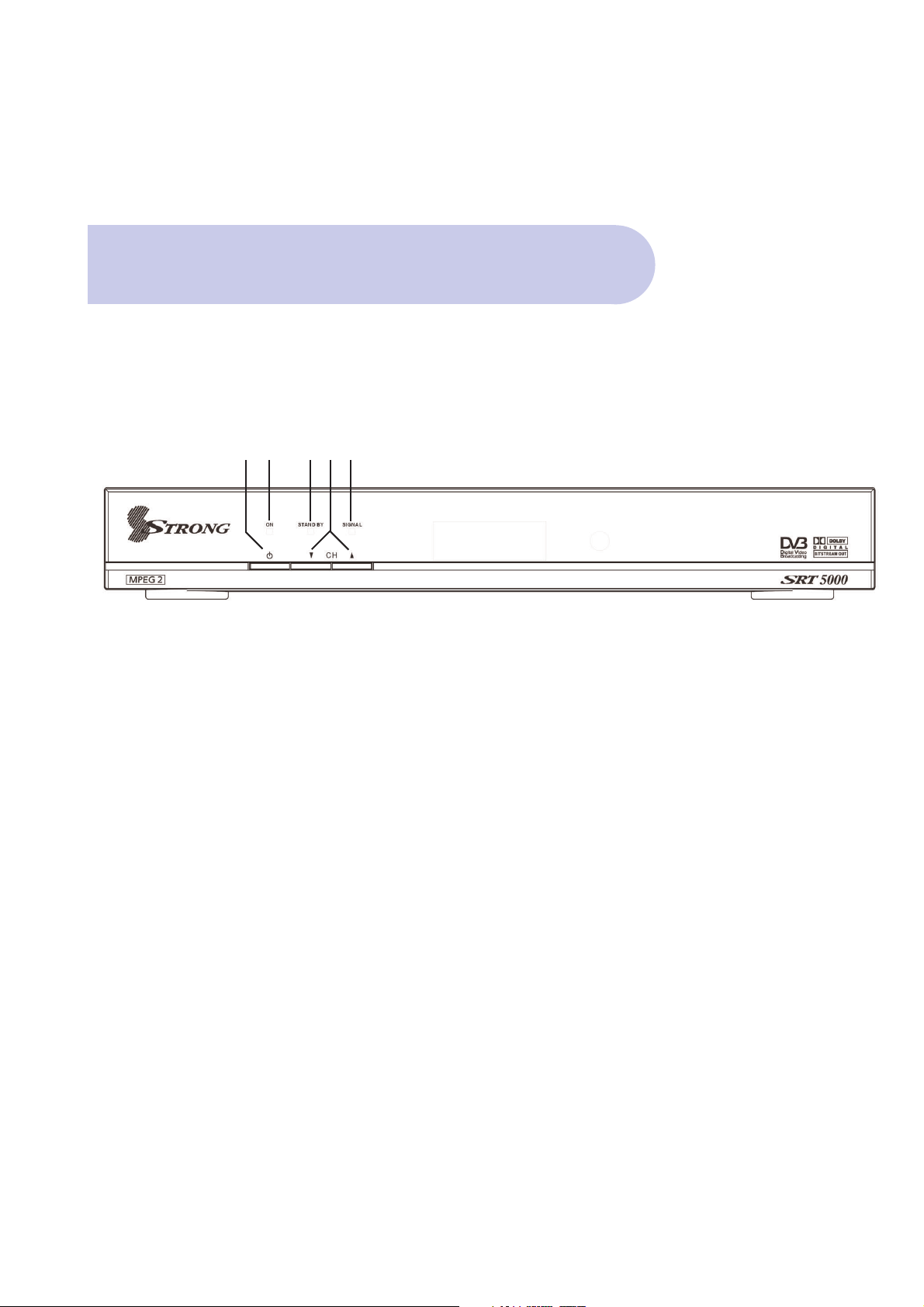
Front Panel
5
Control Functions
1. Power and Standby Mode Button
To switch the Receiver On/OFF and to switch to
‘Standby’ Mode.
2. ON Indicator
3. Signal Received indicator
4. Standby indicator
5. Channel UP/DOWN selector buttons
12 453
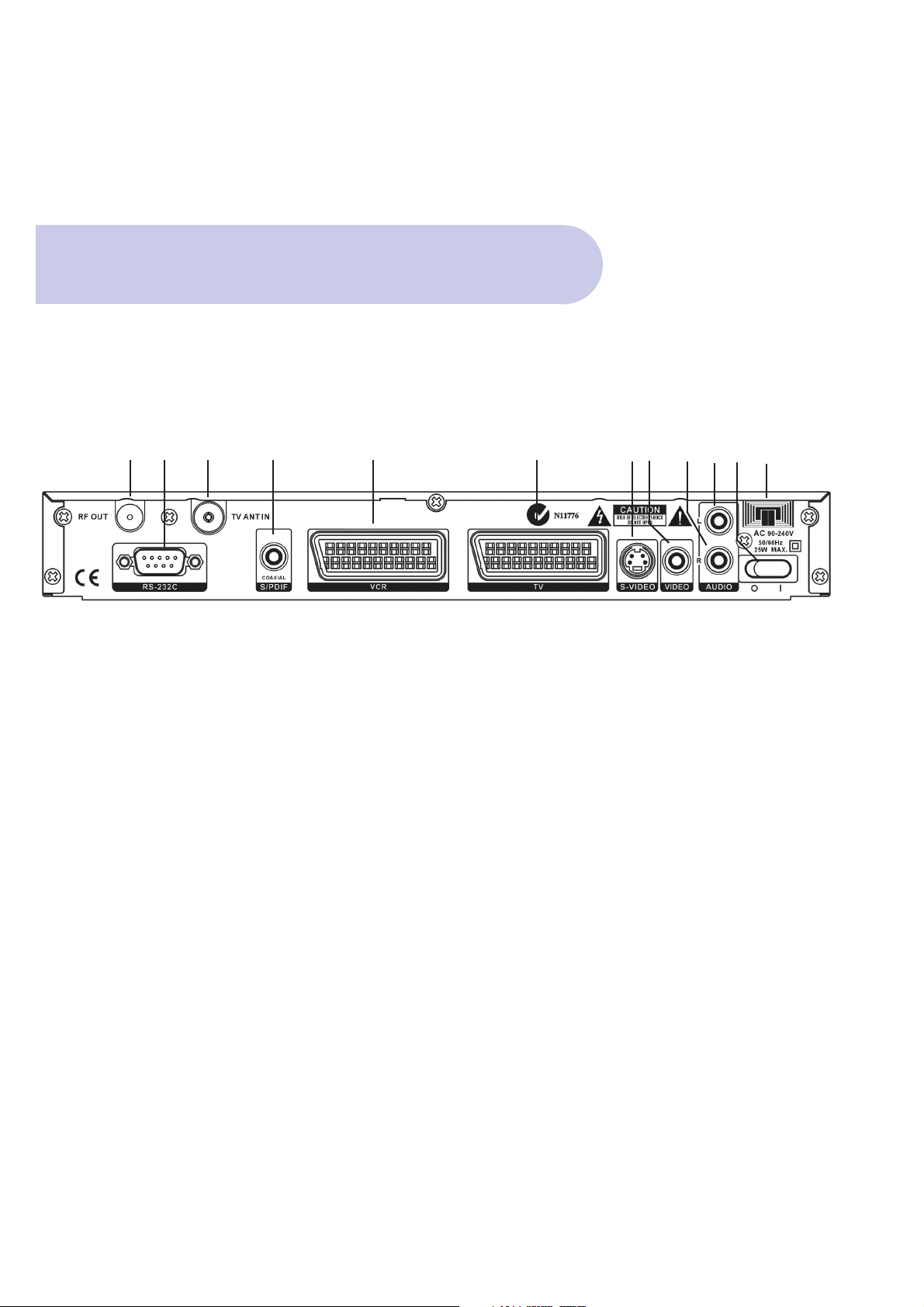
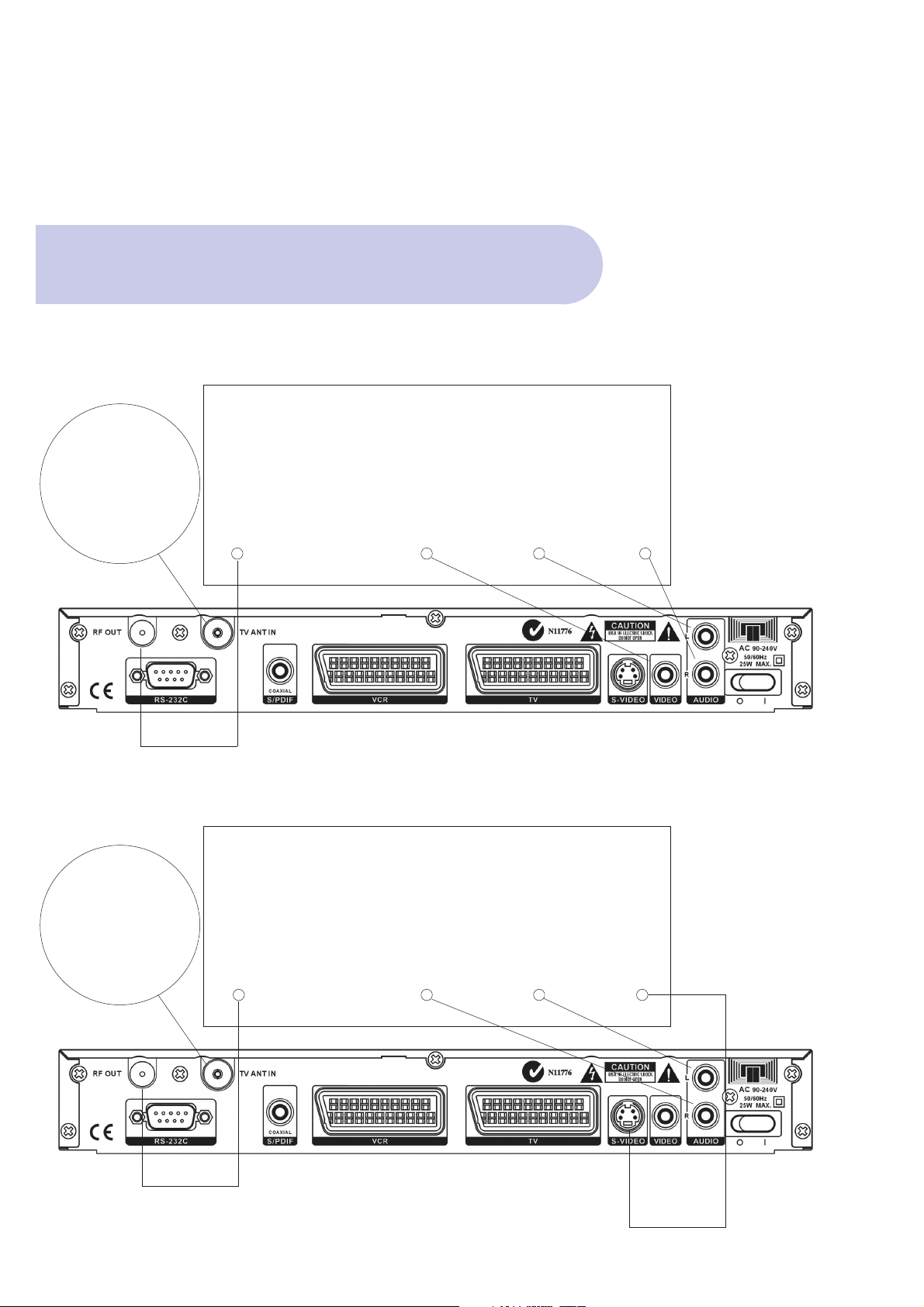
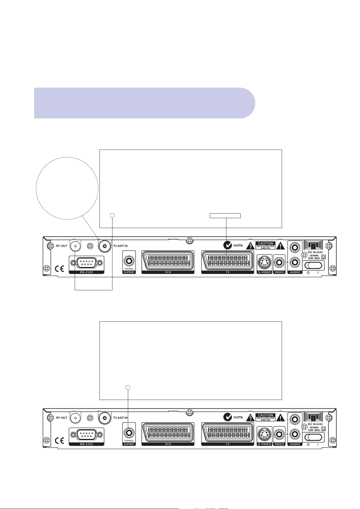
Name Connector Function
1 RF OUT To TV Loop Out IEC 169-2 male Aerial Signal Pass Through
2 RS-232C DB-9 Serial Port
3 TV ANT IN Aerial IEC 169-2 female Input from Antenna to Receiver
4 Coaxial SPDIF RCA cinch Digital Audio Output
5 VCR Scart Scart Output to VCR
6 TV Scart Scart Output to TV
7 S-Video Y/C 4 Pin Mini Din S-Video Ouput
8 Video (Yellow) RCA cinch CVBS (Composite) Output
9 Audio R (Red) RCA cinch Right Audio Output
10 Audio L (White) RCA cinch Left Audio Output
11 0/1 Switch Power
12 240V Input Mains Power
6
Connections
Back Panel
12 3 4 5 6 789101112
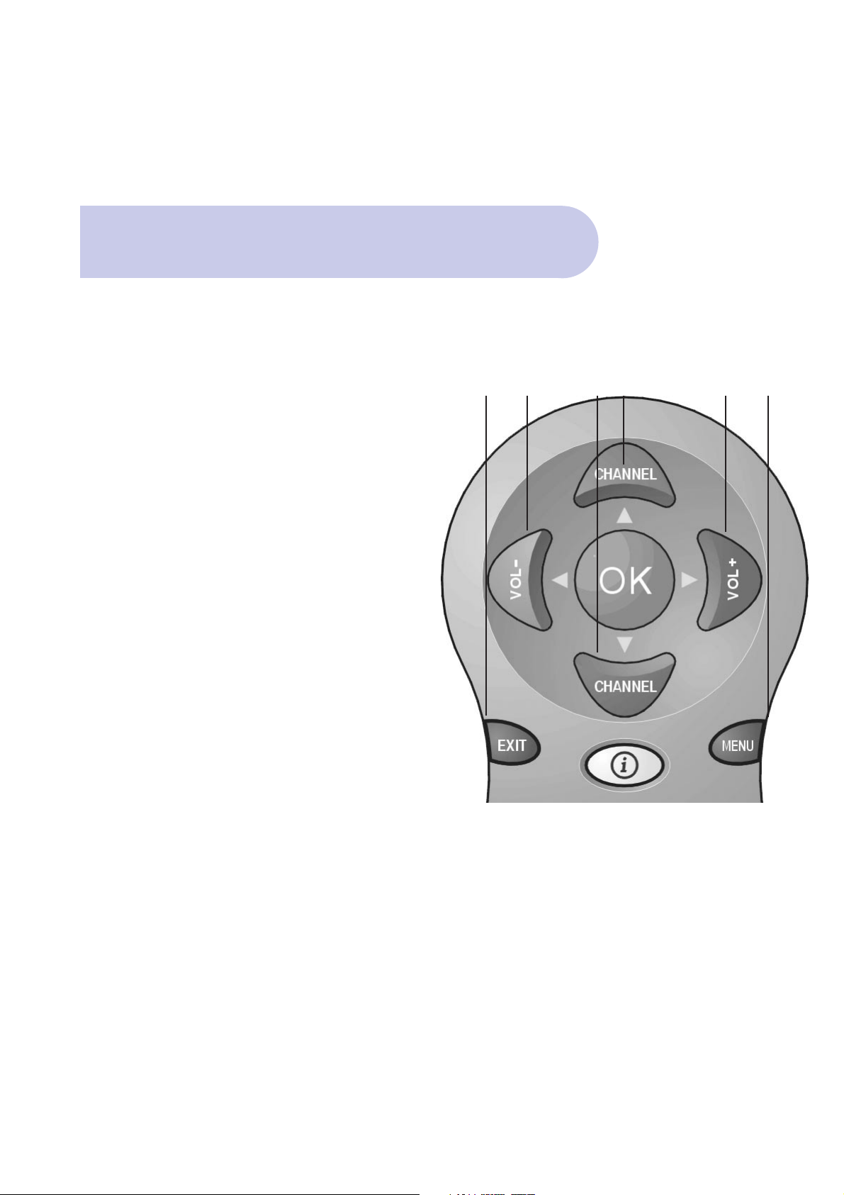
On Screen Menu
7
The Important Buttons
Within this Instruction Manual will be References to
various Buttons on the Remote Control to access
various menus.
These important Buttons are:
1. MENU
To Access the Main Menu
2. EXIT
To move back to previous Menu and Exit Menu
3. SCROLL LEFT Button / SCROLL RIGHT Button
/ SCROLL UP Button/ SCROLL DOWN Button
To access, highlight and select each topic and mode,
within each menu.
The colour buttons provide quick access through the
menu system.
23 33 3 1
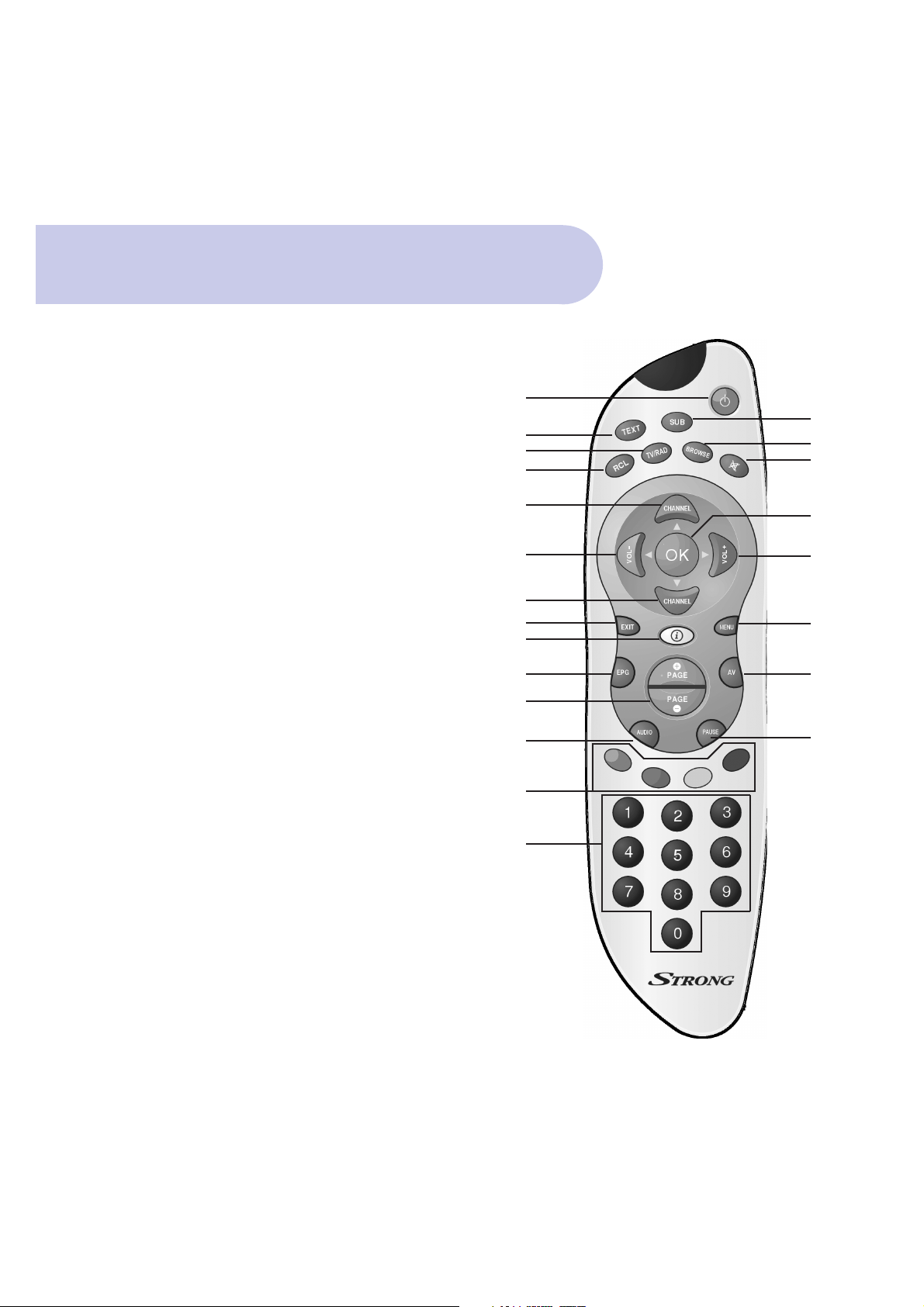
1. POWER-STANBY ON/OFF - Switches the Receiver in or out of
Standby Mode
2. SUB - To select Captions Subtitles (when broadcast)
3. TEXT - Enables / Disables Teletext.
4. TV/RAD - Switches between TV and Radio mode
5. BROWSE - Displays the list of programs in memory.
6. MUTE - Sound ON / OFF
7. RCL- Recall Button - Switch between current and previous program
8. CHANNEL - Navigating within the On Screen Display Menus
(OSD) or stepping through the channels
9. OK - To confirm actions in the menu systems.
10. VOL+ & VOL - Navigating within the OSD Menus (left / right)
or for adjusting the volume.
11. MENU - The main menu for setting up the receiver.
12. EXIT - Exits the current On Screen Display page.
13. I INFORMATION - Shows program information
14. AV - Selects TV or Digital TV by changing the status of Pin 8
in the Scart connector
15. EPG–Program Information - Display the EPG (Electronic
Program Guide)
16. PAGE+ & PAGE- for Aspect Ratio - Change the aspect ratio to
your preference: 4:3, 16:9
17. PAUSE - Pauses the picture.
18. AUDIO - Displays all available audio channels
19. FUNCTION - The four coloured buttons are used for
functions in the menus.
20. 0 - 9 NUMERIC - Direct entry of numerical functions for menus
or channel selection
8
2
5
6
9
10
11
14
17
1
3
4
7
8
10
8
12
13
15
16
18
19
20
Remote Control Functions

Remote Control
9
Battery Replacement
How to insert Battery
• Open the cover at the top of the rear side of the
remote control.
• Insert Two AAA type batteries (1.5V) to be aligned
with appropriate +/- polarity.
Accident prevention
• Do not recharge heat or dissemble the battery.
• Do not cross +/- polarities.
• If Remote control is not going to be used for long
periods, remove the batteries.
Range of operation
• The remote control can be detected by the receiver
within an angle of 30 degrees to the left or right.
• The transmission distance of the remote control is
7m in direct line of sight.
• If remote control is not operating correctly,
replace batteries
• Disturbances from peripheral devises might occur.
Ensure that other product which might cause
interference are placed further away from the receiver.
A. CVBS (Composite) via the supplied RCA Lead
10
Connection Examples
TV
RF IN Video L Audio R Audio
B. Separate S-Video (Y/C) Connector
TV Antenna
TV
RF IN R Audio L Audio S Video
TV Antenna
(Yellow) (White) (Red)
(Red) (White)
11
Connection Examples
C. SCART Connection for RGB or CVBS (Composite)
TV
RF IN TV SCART
SPDIF Coaxial Connection for Dolby Digital
TV Antenna
Audio Decoder Amplifier
SPDIF COAXIAL

For connection of the SRT 5000 there are number of
alternatives depending what is your preference and
the connection types on your TV.
Please connect by either of the following methods A.
B. C. (D. is mandatory for antenna connection)
IMPORTANT: Refer to Page 3 of the Instruction Manual
for the Connector Reference Numbers listed below.
12
How to Connect
If your TV includes a 4 Pin Mini Din S-Video
connector, you may choose to connect in this way.
Connector 7 SVHS S-Video
S-Video connector (connector 7) on the rear panel
and unit can be connected to the TV this way. (You
will need to purchase S-Video Lead separately)
Important: Using this separate S-Video (Y/C) for your
Video connection, you will need to make connections
for Audio.
For Audio, this can be done by using the supplied
RCA cable by connecting to Connector 9 for Right
Audio (RCA Red) and Connector 10 for Left Audio
(RCA White), and then connect to appropriate RCA
audio connectors of your TV.
These Left (white) & Right (Red) RCA Audio
connections will provide MPEGA-2 Stereo.
If you require Dolby Digital Audio Output (through
you’re Dolby Digital Decoder Amplifier) please refer to
Note: DOLBY DIGITAL AUDIO.
B. Separate S-Video (Y/C)
Connector
A. CVBS (Composite) via
the supplied RCA Lead
You can connect to your TV with the supplied RCA
cable to give you Video and Audio. This will give you
CVBS (Composite Video & MPEG-2 Stereo for Audio)
Connector 8
VIDEO (Yellow)
RCA cinch Composite video output
Connector 9
AUDIO Right (Red)
RCA cinch Right audio output
Connector 10
AUDIO Left (White)
RCA cinch Left audio output

How to Connect
13
D. Connecting the Antenna
Connect TV Antenna to Connector 3 (Aerial)
Connector 3 Aerial IEC 169-2 female Input from
Antenna to Receiver
Video Mode of your TV
Having made the above connections to suit your
requirements: The next step is to make certain you
have selected a Video Mode on your Television from
your TV Remote Control
Your Receiver is now ready to be operational
Video Mode of your TV
Having made the above connections to suit your
requirements: The next step is to make certain you
have selected a Video Mode on your Television from
your TV Remote Control
Your Receiver is now ready to be operational
If your TV includes a 21 Pin Scart Connector, you
may choose to connect in this way and select your
choice of RGB or CVBS (Composite).
(You will need to Purchase Scart Lead separately)
(Connector 6)
TV SCART
SCART
21 pin Scart output to TV:
2 video signals to choose from:
RGB
CVBS (composite)
Also, by using Scart Output, Audio MPEG-2 is included
If you require Dolby Digital Audio Output (through
your Dolby Digital Decoder Amplifier), please refer to
Note DOLBY DIGITAL AUDIO.
C. SCART Connection for:
RGB or CVBS (Composite)

14
• On the rear panel, select the 1 position of the 0/1
switch and RED standby light will be viewed on the
Display, including 4 horizontal lines.
• Push the RED Power Button on the remote control
and a Welcome Banner will
appear listing 4 topics.
Power On & Auto Scan
• On the remote control, push the Green button for
Scan All Channels.
• Scan All Channels banner will appear
prompting Yes / NO
• Using R & L Scroll buttons, select YES, which will
then be highlighted
• Push OK button on the Remote Control and Unit will
now begin to scan and lock in all available
frequencies in your area.
This will take approximately one minute.

15
• Once Scan has been completed, Tuning Banner will
state OK.
Power On & Auto Scan
• Push OK and Welcome Banner will be viewed
overlaying the broadcast picture.
• Push EXIT button and full broadcast picture
will be viewed.

16
Assure the correct A/V mode has been selected
in the Menu.
• Push the MENU Button, and Welcome Banner
will appear.
• Push the BLUE Button for Main Menu.
• Banner at the top of the TV screen will be viewed
listing: Installation / Set Up / Information.
The Correct A/V Mode
• Scroll to & select Set Up by pushing OK Button and
4 topics will appear.
• Scroll down to Setting & push OK, and 5 topics will
be viewed.

17
• Scroll down to TV Set up & Push OK.
• Scroll down to Video Type and using either Left or
Right scroll button, select your preferred Video
Mode; I.e. RGB or Composite (CVBS)
• Push OK and banner will indicated ‘Success”
• Push EXIT 3 times to return to normal TV broadcast.
The Correct A/V Mode

18
If you have a Dolby Digital Decoder Amplifier, you can
connect to the amplifier by Coaxial Cable (purchased
separately). This connection will provide for Dolby
Digital Output when broadcast.
Connector 4 is the Digital audio output.
To ‘Enable’ Dolby Digital to be heard when transmitted
within the broadcast stream, you will need to select
Dolby Digital In the TV Set Up Menu, followed by
selection of the Audio Button on the remote control.
Dolby Digital Audio
• Push the MENU Button, and Welcome Banner will appear.
• Push the BLUE Button for Main Menu.
• Banner at the top of the TV screen will be viewed listing:
Installation / Set Up / Information.
• Scroll to & select Set Up by pushing OK Button
and 4 topics will appear.
• Scroll down to Setting & push OK, and 5 topics will be
viewed.
• Scroll down to TV Set Up & Push OK.
• TV Set up banner will appear listing 10 topics.
• Scroll down to Audio and select Dolby Digital.
• Scroll down and select Dolby Symbol and Push OK.
• Push OK.
• Push Exit 3 times to return to normal TV broadcast.
IMPORTANT: If broadcaster is not transmitting in
Dolby Digital at that time, you will not be able to view
or select the Dolby symbol in the menu

Time Setting
19
Automatic Input
The Factory Default Timer Setting is AUTO and therefore
time is automatically adjusted totally in line with the
“Time Print” information in each broadcasters signal.
Also, Factory Default for daylight saving time
(Summer Time) is in the OFF position.
Although, the preferred option is to leave timer setting
in the factory default Auto mode, you can choose to
adjust manually.
Manual Input
• Push the MENU Button, and Welcome Banner will appear.
• Push the BLUE Button for Main Menu.
• Banner at the top of the TV screen will be viewed
listing: Installation / Set Up / Information.
• Scroll to & select Set Up by pushing OK Button and
4 topics will appear.
• Scroll down to Setting & push OK, and 5 topics will
be viewed.
• Scroll down to Timer Set Up & Push OK.
• Timer Set Up banner will appear, with setting in the
default Auto mode,
• Using either Left or Right scroll button, select Manual Mode
• Scroll Down to Date and Time and using Right Scroll
button input date and time via your selection on numbers buttons on the remote control.
• Push OK to confirm
• Push EXIT 3 times to return to normal TV broadcast.

20
To check existing levels
To assure that you can receive adequate picture quality for digital transmissions, it is very important to
check that you have enough Signal Level and Quality
(signal to noise ratio) through your antenna system.
Level: Ideal is 100 % Quality: Ideal is 100%
Minimum is 50% Minimum is 50%
• Push the MENU Button, and Welcome Banner will
appear.
• Push the BLUE Button for Main Menu.
• Banner at the top of the TV screen will be viewed
listing: Installation / Set Up / Information.
• Scroll to Installation and push OK. Select Aerial
Banner and Push Ok
• Select Adjust Aerial banner and push OK.
• Adjust Aerial banner will be viewed.
Checking your Aerial Signal

21
• Push Red (View) button and channels will be
displayed with signal and quality level %
• Push Yellow (Channel) button to highlight channel
section at top of banner.
• Use left and Right scroll buttons to change
channels. When % indicators are indicated, push
Red (View) button to list the channels.
• Push Exit 4 times to return to normal TV broadcast.
Checking your Aerial Signal
Adjusting aerial for optimum signal
There may be circumstances where signal strength
may not be adequate to receive consistent Digital
Reception. In this circumstance, re adjusting your
antenna may assist.
As you alter the position of your antenna, you will be
able to view the resultant signal strength change.
All of these connections and procedures completes
the Installation; however there are other connections
that can be made

22
For Aerial Signal Pass through
to your TV or VCR/DVD
Connector 1 - TV Loop Out
This is the signal coming from your antenna and
passing through the SRT 5000
This can be used for a variety of purposes as per
items A and B as follows.
A. With a separately purchased RF Lead, you can
connect from this connector to your TV antenna IN.
This enables you to switch back to normal analogue
viewing. I.e. you would switch back to normal TV analogue mode by pressing the TV Mode button on your
TV Remote Control.
B. You can choose to connect RF from this connector
to your VCR (separately purchased Lead) which will
enable you to watch a normal Digital Broadcast
Channel through the SRT 5000 and at the same time
you can record a different broadcast channel into the
VCR.
Therefore, as you are watching your digital channel
through the SRT 5000 you would select a channel via
your VCR Remote Control and press Record Button
on your VCR.
E.g. you may be watching the Digital transmission of
CH 7 through the SRT 5000 as normal and recording
CH 9 RF analogue through your attached VCR.
VCR AUX Scart (CVBS
Composite) for Video Out
On the rear panel there is a Second Scart called VCR
Scart (Connector 5)
(Requires separately purchased Scart Lead for connection to VCR or DVD)
This will enable you to RECORD to your attached
video devices
Push Record on your VCR / DVD Remote Control.

23
Pushing the RCL (Blue) Button on the remote control
returns you to the last channel that you were watching.
Quick Return to Last Channel
Watched (RCL Button)
Selecting and Changing Channels
There are 2 methods to select and change channels
• Press the required Numeric Button on the Remote
Control.
Please Note: SRT5000 has default
LCN – Logical Channel System
1 = Ten Network & Affiliates
2 = ABC
3 = SBS
7 = Seven Network & Affiliates
9 = Nine Network & Affiliates
• Select and change channels by using the Up/Down
channel buttons.
Volume Control
To adjust Volume UP and DOWN,
press the following buttons on the remote control:
Volume Increase: VOL Button +
Volume Decrease: VOL Button -
Important: The Volume Level is dependant on the
volume level that you firstly set within your TV I.e. via
your TV remote control volume setting.
Volume Mute
Press Mute button on the remote control
Press Mute button again to reactivate sound.
Picture Pause
To pause the picture, push Pause button on the
remote control.
TV or Radio Selection
To switch between TV and Radio, press the TV/RAD
Button.

24
The Electronic Program Guide is a function within each
broadasters digital stream. When broadcast, current
and upcoming program information will be displayed.
• Push the EPG button on the remote control &
Channel Guide banner will be viewed.
EPG Button
• Push the Green (Quick View) button to view
broadcast information.
• Push INFO Button (White Button in Middle of Remote
Control) and Extended Program Information will be viewed.
Note: Extended program Information can be viewed any
time. When watching normal TV broadcast, Push INFO
button to view.
With the Channel Guide Banner Open, you can also choose
to input Event Time to allow the event number, program,
time, date and duration for VCR Recording to be set.
• Push the Red (Time Program) button and follow the
instruction detailed under Event Timer within this
instruction manual.

Setting Aspect Ratio
25
There are 2 methods to Set and Switch between your preferred Aspect Ratio:
I.e. 4:3 Letterbox / 4:3 Full Screen / 16:9 Full Screen.
Menu Setting for Aspect Ratio
• Push the MENU Button, and Welcome Banner
will appear.
• Push the BLUE Button for Main Menu.
• Banner at the top of the TV screen will be viewed
listing: Installation / Set Up / Information.
• Scroll to & select Set Up by pushing OK Button and
4 topics will appear.
• Scroll down to Setting & push OK, and 5 topics will
be viewed.
• Scroll down to TV Set up & Push OK.
• TV Set Up banner will appear listing 10 topics.
• Scroll down to Aspect Ratio and using either Left or
Right scroll button, select your preferred mode
i.e 4:3, 4:3 Letterbox, 16:9 Wide Screen.
• Push OK and banner will indicate ‘Success’
• Push EXIT 3 times to return to normal TV broadcast.
Hot Key Buttons for Aspect Ratio Change
Whilst viewing a broadcast program, you can change
the aspect ratio to your preference via the remote
control by pushing either the
+ Page Button or the – Page Button.

26
Captions ON/OFF
IMPORTANT: Is dependant on when transmitted by
broadcast stream
• To view Captions, Press SUB Button
• To turn Captions OFF, push Exit.
• To view teletext, select a Channel 7 broadcast
station.
• Press TEXT Button.
• To select your preferred Teletext topics, enter the
topic number via the numeric buttons the remote
control.
• To turn Teletext OFF and return to normal viewing,
push EXIT button.
Teletext

Channels are automatically scanned and stored in
Broadcast Frequency Order which is normally ideal.
However if required, you can also group Favourite
Channels together by subject, content or other heading.
There are 4 default headings provided; they can be
renamed.
The default names are: Music / Film / News / Sport
• Push the MENU Button, and Welcome Banner will appear.
• Push the BLUE Button for Main Menu.
• Banner at the top of the TV screen will be viewed
listing: Installation / Set Up / Information.
• Scroll to & select Set Up by pushing OK Button and
4 topics will appear.
• Scroll Down and select Channels & push OK
• Select Favourite Set Up & push OK
• Favourite Banner will appear, listing the 4 default
headings as above.
Using the coloured buttons to coincide with each
Heading, you can lock in your selected favourite channel/s: i.e. Orange Button = Music / Green Button = Film /
Yellow Button = News / Blue Button = Sport
Select your channel on the left of the banner and push
the appropriate colour button.
As you make each selection an Icon will be listed beside
each channel in accordance to your selection.
Once you have completed your input, push OK and success banner will be viewed.
Push Exit 3 times to return to normal TV broadcast.
As you are viewing your normal TV broadcasts; to
access each of your Favourite’s Channels, push the
appropriate Colour button.
27
Favourite Channel Listing

If you want to delete channels from your Favourites
Listing, with the *Favourite Banner open, push the
selected Colour button and Icon will be removed,
thus deleting that channel from your Favourites List.
Push Exit 4 times to return to normal TV broadcast.
28
Deleting Channels from Favourites
Renaming the 4 Default Favourites Headings
You can choose to change the name of the default
headings.
• Have the *Favourite Banner open.
• Push the Information Button (White button near the
centre of the Remote Control)
• Rename Banner will now be viewed.
• With the Channel Favourite selected verified by the
ICON, input your new heading via the numeric
buttons on the remote control.
• Push OK to confirm.
• Push Exit 4 times to return to normal TV broadcast.

Service Set Up
29
Arrange All Channels
• Push the MENU Button, and Welcome Banner
will appear.
• Push the BLUE Button for Main Menu.
To Delete a Channel
• Push Yellow (Arrange Channel) button on the remote
control and Service Set Up banner will appear.
• With channel highlighted, Push Red (Delete) button
and an x Icon will appear beside the selected channel.
• Push OK and channel will be deleted

30
Service Set Up
To Lock a Channel
• This will then require the password to be input to
Access that Channel.
• With Channel Highlighted, Push Yellow (Lock) button
and L icon will appear beside the selected channel.
• Push OK to confirm
Once you have placed a channel in Lock mode; as
you are watching normal TV broadcasts, when you
select that channel, you will be prompted to input
password.
Once password has been entered, channel broadcast
will be viewed.
To Rename a Channel
• With channel selected, Push Blue (Rename) button
and Key Pad Banner will be viewed.
• Enter your preferred channel name via the remote
control numeric buttons.
• Push OK to confirm.

31
Via Browse
• Push the Browse Button on the remote control to
overview all of your stored channels.
In view will be a Browse Banner.
Each channel will be listed together with a small
picture of the broadcast.
Scroll Up/Down Buttons will move you through the list.
Push OK to view the broadcast or push Exit to return
to normal TV broadcast.
• With the Browse Banner open, push the Green
button to list your channels either A-Z or Z-A
Program List & List Order
Language Setting
The default setting is English however you can choose to
change to another language for Menu language description
• Push the MENU Button, and Welcome Banner will appear.
• Push the BLUE Button for Main Menu.
• Banner at the top of the TV screen will be viewed
listing: Installation / Set Up / Information.
• Scroll to & select Installation by pushing OK Button
and 2 topics will appear.
• Scroll down to and select Language.
• Language banner will appear.
• Scroll down to select your preferred language mode.
• Push OK to confirm.
. Push Exit 3 times to return to normal TV broadcast.

32
This allows for 6 timer entries.
This menu allows the event number, program, time,
date and duration for VCR Recording to be set.
IMPORTANT: Can only function when your VCR /
DVD has been programmed to coincide with each
event accordingly.
• Push the MENU Button, and Welcome Banner
will appear.
• Push the BLUE Button for Main Menu.
• Banner at the top of the TV screen will be viewed
listing: Installation / Set Up / Information.
• Scroll to & select Set Up by pushing OK Button and
4 topics will appear.
• Scroll down to Setting & push OK, and 5 topics will
be viewed.
• Scroll down to Timer Event & Push OK.
• Event Timer banner will appear.
Event Timer
Time ID: Select your Event Number, i.e. 1 to 6
Service: Select the Channel Number
Time Mode: Select your recording option,
Off / Once / Daily / Weekly
Date: Enter the date of the recording
Event: Enter the Start Time of the Recording
Duration: Enter the Length of the Recording
Once these details have been entered Push OK
and Success banner will appear.
• Push Exit 4 times to return to normal TV broadcast.

Sleep Timer
This menu allows you to enable an Automatic Power
OFF after a designated period
• Push the MENU Button, and Welcome Banner
will appear.
• Push the BLUE Button for Main Menu.
• Banner at the top of the TV screen will be viewed
listing: Installation / Set Up / Information.
• Scroll to & select Set Up by pushing OK Button and
4 topics will appear.
• Scroll down to Setting & push OK, and 5 topics will
be viewed.
• Scroll down to Sleep Timer & Push OK.
• Sleep Timer banner will appear.
• Using Left and Right Scroll buttons, press to select
desired Time Off – Up to maximum of 120 minutes.
• Push Ok to confirm
• Push Exit 3 times to return to normal TV broadcast
33

Although the default 4 digit password is 0000,
you can set your own password if preferred.
• Push the MENU Button, and Welcome Banner
will appear.
• Push the BLUE Button for Main Menu.
• Banner at the top of the TV screen will be viewed
listing: Installation / Set Up / Information.
• Scroll to & select Set Up by pushing OK Button and
4 topics will appear.
• Scroll down to Setting & push OK, and 5 topics will
be viewed.
• Scroll down to New Password & Push OK.
• New Password banner will appear.
• Enter the Current Password
(Factory Default is 0000)
• Enter new password. Input by your selection by
numeric buttons on the remote control.
• Enter password again to confirm
• Banner will confirm Success
• Push EXIT 3 times to return to normal
TV broadcast.
34
Selecting New Password

Colour Set Up
In the Advanced Menu you can set up the colour
appearance of each On Screen Display Menu:
Header Shading Header Text Background
Heading Text Colour Background
Text Colour Focus Text Shade
Focus Text Colour Background Border
Control Background Main Menu Highlight Colour
Channel Banner Highlight
The colours are produced by varying the percentage
of Red, Blue, and Green
• Push the MENU Button, and Welcome Banner
will appear.
• Push the BLUE Button for Main Menu.
• Banner at the top of the TV screen will be viewed
listing: Installation / Set Up / Information.
• Scroll to & select Set Up by pushing OK Button
and 4 topics will appear.
• Scroll down to Advanced & push OK, and 5 topics
will be viewed.
• Scroll down to Colour Set Up & Push OK.
• Colour Set Up banner will be viewed
• Select the heading required for adjustment
• Using Up / Down scroll buttons, select the
colour Type
• Using Right & Left scroll buttons, adjust to your
preferred setting
• Push OK and success banner will be viewed.
• Push Exit to view normal TV broadcast.
35

Although you have ‘Auto Scanned’ your receiver to
lock in available frequencies in your location, it is also
possible to initiate a Manual Scan. This enables the
possibility of scanning and locking in a channel that
may not have been selected by the auto scan.
• Push the MENU Button, and Welcome Banner
will appear.
• Push the BLUE Button for Main Menu.
• Banner at the top of the TV screen will be viewed
listing: Installation / Set Up / Information.
• Scroll to & select Set Up by pushing OK Button and
4 topics will appear.
• Scroll down to Scan banner & push OK and 3
menus will be viewed.
• Select Scan Channel and push OK, Scan Channel
Banner will now be viewed.
At the bottom of the banner you will see a Green Icon
for Frequency (Freq)
• Push Green (Freq) button and frequency sector in
the banner will be highlighted.
• Enter the Frequency number you are searching for
via the remote controls numeric buttons.
• Scroll down to OK to Scan and push OK.
• With the Channel now found, Tuning OK banner
will be viewed.
• Push OK to confirm.
• Push Exit 3 times to return to normal TV broadcast.
36
Manual Scan

Factory Reset
Enables Receiver to be reset back to
Factory Default Settings.
• Push the MENU Button, and Welcome Banner
will appear.
• Push the BLUE Button for Main Menu.
• Banner at the top of the TV screen will be viewed
listing: Installation / Set Up / Information.
• Scroll to & select Set Up by pushing OK Button and
4 topics will appear.
• Scroll down to Advanced & push OK, and 5 topics
will be viewed.
• Scroll down to Factory Reset & Push OK.
• Password Banner will be viewed,
enter 4 digit password
• Warning banner will be view prompting Yes / No
• Select YES, push OK and Reset will be actioned.
37

This menu details information on the receiver’s
Software and Hardware version
• Push the MENU Button, and Welcome Banner
will appear.
• Push the BLUE Button for Main Menu.
• Banner at the top of the TV screen will be viewed
listing: Installation / Set Up / Information.
• Scroll to & select Information by pushing OK Button
and then select sub menu Information.
Information banner will now be viewed.
• Push Exit 3 times to view normal TV broadcast.
38
Information Menu

Symptoms
LED on front panel does
not light up
No Picture & Sound
Picture and/or Audio Glitch
No Sound
Remote Control not working
Solution
Check the main power cord is
plugged into the wall outlet and
check that the power connector of
the unit is plugged in.
Check your TV has been set to
correct AV Mode.
Check you selected connections:
Scart / S-Video / RCA / RF / Ant.
Check Signal Level & Quality level
indicators of the Receiver to verity
whether your antenna signal is
adequate.
Check all antenna cabling used is
Quad Shielded type, including the
antenna Fly Lead from the wall
socket to the receiver.
Press the MUTE button on the
remote control of your receiver
and TV.
Set your desired TV volume level
via TV remote control.
• Insert batteries
• Change batteries
• Aim at the receiver
Troubleshooting
There may be various reasons for abnormal operation
of the unit.
Occasionally receivers can hang-up (just like a PC).
In this circumstance, it is recommended to reset the
receiver by disconnecting if from mains power.
Wait 30 seconds and connect to mains power again
and check if receiver is working correctly.
If there is still incorrect operation, please refer to the
following table for the indicated problem.
39
Possible Cause
AC power is disconnected
TV Mode is Incorrect
Problem in cable connections
between receiver & TV
Insufficient Signal Strength
for Digital
Electrical Interference
The receiver or the TV
is in MUTE mode
Initial Volume Level has not been
set on your TV
• Batteries not inserted
• Batteries exhausted
• Outside range of operation

Demodulator Supports
• COFDM
• 2K / 8K
• Guard 1 / 2, 1 / 4, 1 / 8, 1 / 16, 1 / 32
• FEC, 1 / 2, 2 / 3, 3 / 4, 4 /5, 5 / 6, 7 / 8
• QPSK, 16 QAM, 64 QAM.
CPU & Memories
• 32 Bit RISC
• 2M FLASH
• 8M SDRAM
RF Input
• IEC Female 9.5mm.
• Frequency range VHF: 147 to 429.9MHz / UHF: 430.0 to 858.0Mhz
• Bandwidth 8 / 7 MHz
• Exceeds DTV targets.
• RF Loop through
• 1000 Channel
Video Decoder
• MPEG-2
• Data rates up to 15Mbits / S
• Video format 4:3, 16:9
Audio Decoder
• MPEG-2 Layer I & II MONO / STEREO / dual channel
• Data rates up to 384Kbits/S
AV Outputs
• Composite video to SCART
• RGB video to SCART
• Stereo audio to SCART
• Coaxial S/PDIF
• S-VHS
• Composite Video & Stereo audio by RCA
Software Update
• 9 pin RS-232 connector
Dimension
• W 280mm X H 40.5mm X D 170mm (Case) / 185mm to end of connectors
Power
• 240V ~ +/- 10% 50/60Hz
40
Specifications

STRONG & Co. (FAR EAST), LTD.
P. O. Box: 85, YOKOHAMA. KANAGAWA-KEN
JAPAN 231-91 FAX: +81 45 662-4957
Website:www.strong-technologies.com
E-mail: tech@strong-technologies.com
 Loading...