

Page 1

Service Manual
(SRT4355)
Page 2

Contents
1. Technical specifications
2. Block Diagram
3. Circuit Drawing
4. List of Error codes
5 Trouble Shooting
3.1 Trouble shooting
3.2 Check point about badness STB
6. Materials list
6.1 Main PCB materials list
6.2 Front PCB materials list
7. Software download instructions(OTA and PC download)
7.1 Program Download
7.2 System Upgrade
8. Specification of required cables for software download
9. Data Sheet
Page 3
1. Technical specifications
1.1. Conditional Access Interface
PCMCIA
1.2. Tuner & Channel
<Digital Part>
Input Connector F-type, IEC169-24, Female
Frequency Range 950MHz to 2150MHz
Input Impedance 75ohm unbalanced
Signal Level -25 to –65dBm
IF Bandwidth 55MHz
LNB Power Vertical: +13V Horizontal: +18V Current: Max, 400mA
Polarization 13V/18V or Skew Control
22kHz Tone Frequency: 22±4kHz Amplitude: 0.6±0.2V
DiSEqC control Version (1.0 & 1.2) Compatible
Demodulation QPSK
Input Symbol Rate 2-45 Ms/s
FEC Decoder Convolution Code Rate 1/2, 2/3, 3/4, 5/6, and 7/8
2. Slot(type I or type II)
DVB Common Interface Standard
(Viaccess, Nagra Vision, Conax, Cryptoworks, Irdeto, ASTON)
With Constraint Length K=7
1.3. System & Memory
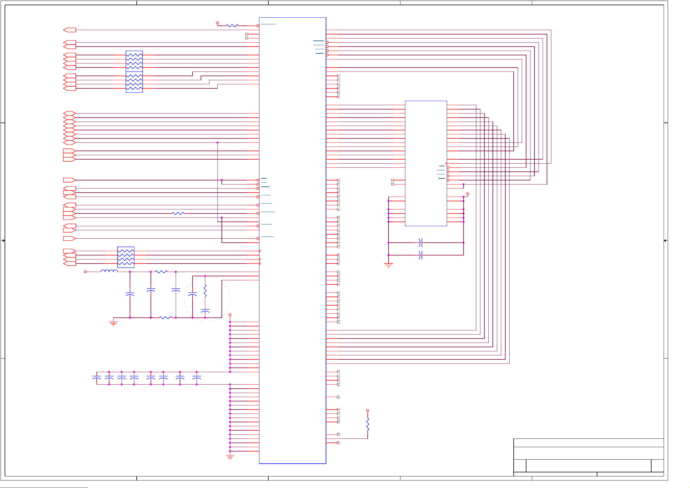
Main Processor L64108(LSI -LOGIC)
Flash Memort 1Mbyte
Program Dram 2Mbyte
EEPROM 8kbyte
Channel Memory
(Total : 3500)
Multi-Satellite UP to 64
Multi-Language Menu English/Spanish/French/Italian/German/Portuguese
Front 7 keys, 4-digit 7–segment display
Remote Controller 30-31 keys, IR Remote Control
Digital Channel: 3000
Analog Channel: 500
Page 4

1.4. MPEG Transport Stream & A/V Decoding
<Digital Part>
Transport Stream MPEG-2 ISO/IEC 13818 Transport Stream Specification
Profile Level MPEG-2 MP@ML
Input Rate Max. 40Mbit/s
Aspect Ratio 4:3, 16:9
Frame Rate 25Hz for PAL, 30Hz for NTSC
Video Resolution 720x576(PAL),720x480(NTSC)
Teletext Through VBI
Audio Decoding MPEG/MusiCam Layer I & II
Audio Mode Single channel/Dual channel joint stereo/Stereo
Frequency Response 20~20kHz, <+/- 2dB
60Hz~18kHz <+/- 0.5dB
Sampling Rate 32, 44.1, 48kHz
1.5. A/V & Date In/Out
TV Scart Output RGB, CVBS, L, R Output with Volume control
VCR Scart In/Out CVBS, L, R In
CVBS, L, R Out
RCA Output CVBS, L, R Output(Yellow, White, Red Hack) with Volume Control
0V/12V Output RCA Jack Output(Black Jack), Max. 150mA
Data Interface RS-232, Bit Rate: 115200baud
Connector: 9-pin D-sub type
1.6. RF-Modulator
RF-Connector 75w IEC169-2, Male/Female
Frequency 470MHz to 860MHz
Output Channel CH 21-69 for the Demodulator
TV Standard PAL B/G/I/D/K Selectable by Menu Setting
Audio Output Mono with Volume Control
Preset Channel CH 40 (or TBD). Soft ware changeable by Menu screen
Page 5
1.7. Power Supply
Input Voltage AC90 to 260V, 50Hz/60Hz
Type PWM Regulator
Power Consumption Max. 40W(without Positioner)
Stand-by Power <= 10W
Protection Separate Internal Fuse
The input shall have the lighting protection
1.8. Physical Specification
Size (WxHxD) 280x55x235mm
Excluding the foot. Foot height is 10mm.
Weight 2.0Kg
1.9. Environmental Condition
Operating Temperature 0~40C
Storage Temperature -10C~+50C
Operating Humidity Range 10~85% RH, Non-condensing
Storage Humidity Range 5~90% RH, Non-condensing
Page 6
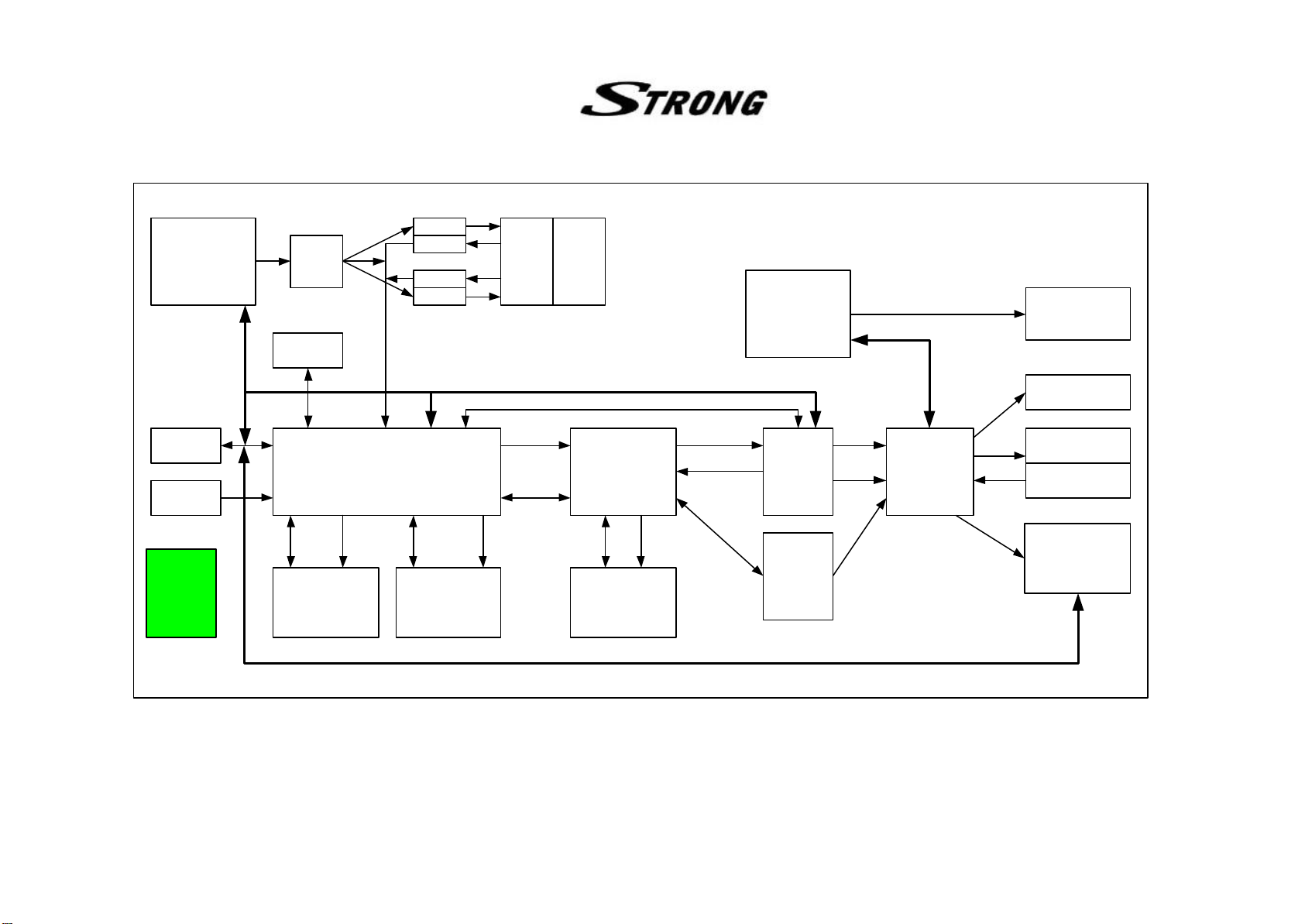
2. Block Diagram
CH_VALID,
CH_CLK,
QPSK NIM
(TBMU30311)
SCL,
SDA
CH_STRT,
PTO[0..7]
74244
RS-232
(DS232AS)
TXD,RXD
74244
74244
74244
74244
TS_VALID,
TS_CLK,
TS[0..7]
Common
Block Diagram
Interface
microcontroller
(AT89C51)
SCL,SDA
TTXDATA, TTXREQ
8-bit
BD[0..7]
I2C(SDL,SCA)
Front Panel
RCA JACK
SMPS
EEPROM
(AT24C64)
VCXO
(27MHz)
MPEG2 Transport with Embeded
MIPS CPU
(L64108)
EDATA
[0..15]
EADDR
[1..20]
BD[0..15] BA[0..9]
Flash ROM
1MByte
(SST39VF800Q)
DRAM 2MByte
(KM416V1204)
AVD[0..7]
AREQ,AVALID
,VREQ,VVALID
SBD[0..15] SBA[0..8]
Audio/Video
Decoder
(L64005)
SDRAM 2MByte
(KM416S1020)
YCRCB[0..7]
VSYNC,HSYNC
LRCLK,BICK,
PCMDATA,
005_ACLK
Video
Encoder
(BT864)
Audio
DAC
(AK4323)
CVBS
RED,
GREEN,
BLUE
L_AUDIO,
R_AUDIO
LEFT_A,
RIGHT_A
Audio/Video
Switch
(CXA2126)
RF_Audio,
RF_Video
TV SCART
VIDEO SCART
RF Modulator
(RMUP74055)
Page 7
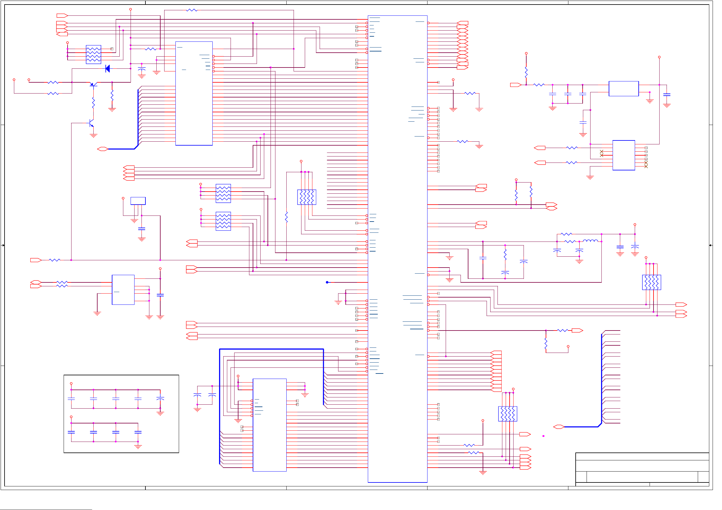
A
ROM_WP
RESETN
DSSCK1N
DSACK0N
R/WN
4 4
5V
3.3VS
R25
R24
3.3V
NC
1K
RA1
1 8
2 7
3 6
4 5
D3
Q11
NC (RLS4148)
KTA1273
0
R9
1K
Q10
DTC114
EDATA[0..15]
EADDR0
EADDR1
EADDR2
EADDR3
3 3
R22
R21
NC
0
0
5
6
7
AT24C64N-10SC-2.7
L64108
VDD와 GND
의
VDD: 2,22,35,38,46,62,92,98,116,121,135,
154,162,180,182,196,214,232
GND:1,21,34,37,45,61,77,78,91,97,115,120,
134,153,161,179,181,190,191,195,213,231
M_FLASH_CTL
SDA
SCL
2 2
R10
ROM_VPP
R8
1K
EDATA[0..15]
5V
U4
VCC
SDA
SCL
WC
GND
SOIC
E0
E1
E2
R59
NC(10k)
13
Vpp
WP
GND
GND
VCC
RY/BY
DATA15
DATA14
DATA13
DATA12
DATA11
DATA10
DATA9
DATA8
DATA7
DATA6
DATA5
DATA4
DATA3
DATA2
DATA1
DATA0
U2
TSOP48
R55
0
C60
104
EDATA15
EDATA14
EDATA13
EDATA12
EDATA11
EDATA10
EDATA9
EDATA8
EDATA7
EDATA6
EDATA5 EADDR6
EDATA4
EDATA3
EDATA2
EDATA1
EDATA0
14
27
46
37
15
45
43
41
39
36
34
32
30
44
42
40
38
35
33
31
29
Am29F800BT-120EC or,SST39VF800A-90-4C-EK
3.3V
U5
DS1811
123
C50
0.1
CS_005N
CASCS
3.3V
INTN2
INTN1
3.3V
8
1
2
3
4
C61
104
RXD2
RXD1
TXD2
TXD1
3.3V
C67
104
C66
104
C65
104
C64
104
E2
+
10/10
C63
104
3.3V
1 1
C71
104
A
C70
104
C69
104
C68
104
B
for intel rom
9
ADDR19
12
RESET
47
BYTE
11
WE
28
OE
26
CE
16
ADDR18
17
ADDR17
48
ADDR16
1
ADDR15
2
ADDR14
3
ADDR13
4
ADDR12
5
ADDR11
6
ADDR10
7
ADDR9
8
ADDR8
18
ADDR7
19
ADDR6
20
ADDR5
21
ADDR4
22
ADDR3
23
ADDR2
24
ADDR1
25
ADDR0
RA23
RA3
C62
104
B
4.7K
4.7K
BA9
BA8
BA7
BA6
BA5
BA4
BA3
BA2
BA1
BA0
18
27
36
45
18
27
36
45
3.3V
U3
21
VCC
6
VCC
1
VCC
29
OE
13
W
31
LCAS
30
UCAS
14
RAS
15
NC
16
NC
28
A9
27
A8
26
A7
25
A6
24
A5
23
A4
20
A3
19
A2
18
A1
17
A0
KM416V1204CJ-6
400mil 42SOJ
R23
1K
BA[9..0]
VSS
VSS
VSS
NC
NC
I/O16
I/O15
I/O14
I/O13
I/O12
I/O11
I/O10
I/O09
I/O08
I/O07
I/O06
I/O05
I/O04
I/O03
I/O02
I/O01
EADDR20
EADDR19
EADDR18
EADDR17
EADDR16
EADDR15
EADDR14
EADDR13
EADDR12
EADDR11
EADDR10
EADDR9
EADDR8
EADDR7
EADDR5
EADDR4
EADDR3
EADDR2
EADDR1
EADDR0
42
37
22
12
11
41
40
39
38
36
35
34
33
10
9
8
7
5
4
3
2
3.3V
C
D
E
U1
54MHz
L64108C
240p PQFP
C
136
145
127
128
129
131
130
133
132
106
105
104
103
102
101
100
126
125
124
123
122
119
118
117
114
113
112
111
110
109
108
107
137
138
146
148
144
152
151
150
149
143
142
141
140
139
187
188
178
183
184
189
186
185
177
176
224
228
222
226
223
227
225
221
220
219
218
217
216
215
212
211
210
209
208
207
206
205
204
203
202
201
200
199
198
197
194
193
192
55
99
96
95
94
93
90
89
88
87
86
85
84
83
82
81
80
79
20
29
28
CS_008
RESET
AS
DS
WR
OE
SIZE1
SIZE0
DSACK1
DSACK0
ADDR23
ADDR22
ADDR21
ADDR20
ADDR19
ADDR18
ADDR17
ADDR16
ADDR15
ADDR14
ADDR13
ADDR12
ADDR11
ADDR10
ADDR9
ADDR8
ADDR7
ADDR6
ADDR5
ADDR4
ADDR3
ADDR2
ADDR1
ADDR0
DATA15
DATA14
DATA13
DATA12
DATA11
DATA10
DATA9
DATA8
DATA7
DATA6
DATA5
DATA4
DATA3
DATA2
DATA1
DATA0
BRQ
BGA
BG
DMRQ
DMAK
CS3
CS2
CS1
CS0
INTR4
INTR3
INTR2
INTR1
INTR0
MCLK
5
OP_MODE1
4
OP_MODE0
CTS1
CTS0
RTS1
RTS0
DTR0
DSR0
RXD2
RXD1
RXD0
TXD2
TXD1
TXD0
WE1
WE0
CAS1H
CAS0H
CAS1L
CAS0L
RAS0
BA9/RAS1
BA8
BA7
BA6
BA5
BA4
BA3
BA2
BA1
BA0
BD15
BD14
BD13
BD12
BD11
BD10
BD9
BD8
BD7
BD6
BD5
BD4
BD3
BD2
BD1
BD0
AREQ
AVALID
AVD7
AVD6
AVD5
AVD4
AVD3
AVD2
AVD1
AVD0
AVERR
VREQ
VVALID
ACLK
AVDD
AVSS
IREF
STROBE
AUTOFD
INIT
SELECTIN
ACK/AUXV
BUSY
PERROR
SELECT
OP_MODE2/PDATA_DIR
FAULT
PDATA7
PDATA6
PDATA5
PDATA4
PDATA3
PDATA2
PDATA1
PDATA0
TTXREQ
TTXDATA
SCL
SDA
SCLK
SDET
PLLVDD
LP2
PLLAGND
PLLVSS
ECLK
IDDTN
ZTEST
SC_CLK1
SC_DETECT1
SC1-I/O
SC_VCC_EN1
SC_VPP_EN1
SC_RST1
SC_CLK0
SC_DETECT0
SC0-I/O
SC_VCC_EN0
SC_VPP_EN0
SC_RST0
SC0_C4
SC0_C8
CCLK
CERR
CVALID
CDATA7
CDATA6
CDATA5
CDATA4
CDATA3
CDATA2
CDATA1
CDATA0
TRST
TDI
TDO
TMS
TCK
GPIO49
GPIO48
GPIO47
GPIO46
GPIO45
GPIO44
GPIO43
GPIO42
GPIO41
GPIO40
60
58
54
53
52
51
50
49
48
47
56
59
57
147
236
235
234
157
158
159
160
171
172
173
174
175
6
170
169
168
167
166
165
164
163
230
229
155
156
7
8
237
239
238
240
36
3
233
74
73
75
76
71
72
66
65
67
68
63
64
69
70
11
10
9
19
18
17
16
15
14
13
12
27
23
24
25
26
33
32
31
30
44
43
42
41
40
39
3.3V
R13
AREQN
AVALID
AVD7
AVD6
AVD5
AVD4
AVD3
AVD2
AVD1
AVD0
ERRORN
VREQN
VVALID
R12
16.9K 1%
4.7K
R19 4.7K
3.3V
R20 4.7K
PWMOUT0
TTXREQ
TTXDATA
27MHz
PWMOUT0
C6
104
D
5V
R16
1K
C7
152p
TS_CLK
CH_ERROR
TS_VALID
TS7
TS6
TS5
TS4
TS3
TS2
3.3V
TS1
TS0
182736
45
3.3V
27MHZ
SYSCLK
R14
3.3K
C8
22p
CLOSE TO CHIP
RA24
10K
R2
620
R5
6.2K(F)
C12
R15
3.3K
D_RSTN
CASEN
FS0
FS1
CH_RST
V_RSTN
103
C1
105
(NC)15pF
SCL
SDA
R17
C9
104
R54
nc(0 ohm)
R56
ROM_VPP
nc (10K)
EADDR[0..17]
3.3V
U39
C2
51pF
1
VCOOUT
8
OUT
VCXO 27MHZ(DIP)
VDD
GND
14
7
C11
0.01uF
C3
R4
33
R3
33
U6
1
I1
2
O1
3
I2
4
O2
5
I3
6
O3
GND7O4
VCC
14
13
I6
12
O6
11
I5
10
O5
9
I4
8
74LCX04M
3.3V
L1
10uH
4.7K
R18
E1
10
ROM_WP
EADDR[0..17]
C10
102
C72
104
EADDR3
EADDR2
EADDR1
EADDR0
EADDR17
EADDR16
EADDR15
EADDR14
EADDR13
EADDR12
EADDR11
EADDR10
EADDR9
EADDR8
EADDR7
EADDR6
EADDR5
EADDR4
+
10/10
5V
182736
45
RA4
10K
UK STRONG
Title
L64108
Size Document Number Rev
SRT4355 1.1
Custom
of
Date: Sheet
E
113Thursday, November 15, 2001
LNBP_OFF
22ON/OFF
POLARITY
CS_008N
EDATA15
EDATA14
EDATA13
EDATA12
EDATA11
EDATA10
EDATA9
EDATA8
EDATA7
EDATA6
EDATA5
RA2
EDATA4
EDATA3
10K
EDATA2
EDATA1
1 8
2 7
3 6
4 5
EDATA0
CS0n
INTN4
T1
BA9
BA8
BA7
BA6
BA5
BA4
BA3
BA2
BA1
BA0
BD15
BD14
BD13
BD12
BD11
BD10
BD9
BD8
BD7
BD6
BD5
BD4
BD3
BD2
BD1
BD0
Page 8
A
B
C
D
E
R27
3.3V
4.7K
BLANKN
HSYNCN
VSYNCN
RA5
YCRCB0
YCRCB1
4 4
3 3
YCRCB2
YCRCB3
YCRCB4
YCRCB5
YCRCB6
YCRCB7
AVD0
AVD1
AVD2
AVD3
AVD4
AVD5
AVD6
AVD7
EADDR1
EADDR2
EADDR3
CS_005N
INTN2
R/WN
DSACK0N
AREQN
AVALID
ERRORN
27MHz
VREQN
VVALID
4 5
3 6
2 7
1 8
4 5
3 6
2 7
1 8
RA6
100
100
R28
150
D_RSTN
RA7
005_ACLK
PCMDATA
BICK
LRCLK
4 5
3 6
2 7
1 8
3.3v
10uH
L2
2 2
100
R29
18
E3
+
10/10
C13
102
R30
18
C14
104
C15
20pF
R31
200
C16
102
3.3V
CLOSE TO CHIP
GND SURFACE
10 mm
C74
C75
104
104
1 1
A
1 mm LINE으로
와
이상 떨어져서 연결
C76
C77
104
104
C78
104
C79
104
C80
104
C81
104
B
131
118
123
159
103
104
105
106
107
108
109
110
125
126
127
132
121
137
133
134
124
114
111
135
102
112
129
143
152
160
101
113
115
117
122
136
144
153
96
97
88
89
90
91
92
93
94
95
79
80
82
87
42
41
68
69
70
11
20
27
40
46
62
72
86
12
28
39
47
51
63
85
98
99
2
1
U7
BYPASS
BLANK
CREF
OSD
HS
VS
PD0
PD1
PD2
PD3
PD4
PD5
PD6
PD7
D0
D1
D2
D3
D4
D5
D6
D7
A0
A1
A2
CS
AS
INTR
READ
WAIT
AREQ
AVALID
ERROR
SCLKI
SERI
VREQ
VVALID
RESET
SYSCLK
ACLK
ASDATA
BCLK
LRCLK
AVDD
LP2
AGND
VDD
VDD
VDD
VDD
VDD
VDD
VDD
VDD
VDD
VDD
VDD
VDD
VDD
GND
GND
GND
GND
GND
GND
GND
GND
GND
GND
GND
GND
GND
GND
GND
GND
GND
L64005
160p PQFP
SCLK
SDQM
SCKE
SRAS
SCAS
SWE
SCS
SBA9
SBA10
SBA11
NC
NC
NC
NC
NC
NC
SBD0
SBD1
SBD2
SBD3
SBD4
SBD5
SBD6
SBD7
SBD8
SBD9
SBD10
SBD11
SBD12
SBD13
SBD14
SBD15
NC
NC
NC
NC
NC
NC
NC
NC
NC
NC
NC
NC
NC
NC
NC
NC
NC
NC
NC
NC
NC
NC
NC
NC
NC
NC
NC
NC
NC
NC
NC
SBA0
SBA1
SBA2
SBA3
SBA4
SBA5
SBA6
SBA7
SBA8
NC
NC
NC
NC
TESTCLK
NC
NC
NC
NC
RSVD
RSVD
RSVD
61
60
59
58
57
56
55
54
53
52
50
49
48
45
44
43
38
37
36
35
34
33
32
31
30
29
26
25
24
23
22
21
19
18
17
16
15
14
13
10
9
8
7
6
5
4
3
158
157
156
155
151
150
149
148
147
146
145
142
141
140
139
138
84
83
78
77
76
75
74
73
71
67
66
65
64
130
81
100
119
128
116
120
154
XDD0
XDD1
CSKE
SRASN
SCASN
SWEN
SCSN
SBA9
SBA10
SBA11
CLK은 다른 SIGNAL과
인접해서 그리지 말 것
.
U8
A10
A11
CKE
CLK
RAS
CAS
WE
LDQM
UDQM
VDD
VDD
VDDQ
VDDQ
VDDQ
VDDQ
A0
A1
A2
A3
A4
A5
A6
A7
A8
A9
CS
21
22
23
24
27
28
29
30
31
32
20
19
34
35
18
17
16
15
14
36
3.3V
1
25
7
13
38
44
SBD0
SBD1
SBD2
SBD3
SBD4
SBD5
SBD6
SBD7
SBD8
SBD9
SBD10
SBD11
SBD12
SBD13
SBD14
SBD15
2
DQ0
3
DQ1
5
DQ2
6
DQ3
8
DQ4
9
DQ5
11
DQ6
12
DQ7
39
DQ8
40
DQ9
42
DQ10
43
DQ11
45
DQ12
46
DQ13
48
DQ14
49
DQ15
33
NC
37
NC
26
VSS
50
VSS
4
VSSQ
10
VSSQ
41
VSSQ
47
VSSQ
KM416S1020BT-G/F10
50p TSOP(II)
104
104
XDA0
XDA1
XDA2
XDA3
XDA4
XDA5
XDA6
XDA7
XDA8
C83
C82
3.3V
R32
4.7K
UK STRONG
Title
L64005
Size Document Number Rev
SRT4355 1.1
Custom
C
D
Date: Sheet
E
113Thursday, November 15, 2001
of
Page 9
A
4 4
B
C
D
E
C17
104
2
C1+
C1TIN1
TIN2
RO1
RO2
GND
6
VO-
VCC
VO+
C2+
C2-
TO1
TO2
RI1
RI2
16
4
5
14
7
13
8
C84
104
C20
104
C19
U9
104
1
C18
3 3
104
3
11
TXD1
RXD1
10
12
9
15
5V
+
E4
10uF/16
BD1
FCM2012C-101
BD2
FCM2012C-101
TXD
RXD
J4
1
6
2
7
3
8
4
9
5
SP232ECN
C21
102
C22
102
3302-09S-AFS-0
2 2
1 1
UK STRONG
Title
RS232C
Size Document Number Rev
A
SRT4355 1.1
Date: Sheet
A
B
C
D
113Thursday, November 15, 2001
of
E
Page 10
A
4 4
B
C
D
E
S5V
S5V
S5V
S5V
R35
1K
PWR_CTL
3 3
Q9
DTC114
S_SCL
S_SDA
HW_MUTE
LNB_DOWN
8051_LNBP_OFF
PCMCIA_A
PCMCIA_B
LOOP_CNTL
M_FLASH_CTL
INTN1
12V_ON/OFF
RESETN
RXD2
TXD2
2 2
RA8
4.7K
182736
45
R33
4.7K
R34
4.7K
E5
10/16
+
C85
104
43
P0.0
42
P0.1
41
P0.2
40
P0.3
39
P0.4
38
P0.5
37
P0.6
36
P0.7
AT89C51-12JI (PLCC)
25
P2.1
26
P2.2
27
P2.3
28
P2.4
31
P2.7
19
/RD(P3.7)
18
/WR(P3.6)
13
TXD(P3.1)
11
RXD(P3.0)
GND
35
44
P1.0
P1.1
P1.2
P1.3
P1.4
P1.5
P1.6
P1.7
P2.0
P2.5
P2.6
10
2
3
4
5
6
7
8
9
24
29
30
14
RESET
EA
VCC
U10
INT0(P3.2)
X2
X1
E6
10/16
+
R36
10K
D1
RLS4148
4 5
S5V
3 6
RA9
10K
S5V
1 8
2 7
J1
1
2
3
4
5
6
7
8
9
10
11
12
13
14
CON14
GND
S5V
182736
20
22
45
RA20
4.7K
182736
45
RA19
4.7K
C23
18pF
11.0592MHz
21
X2
C24
18pF
1 1
UK STRONG
Title
Size Document Number Rev
A
B
C
D
Date: Sheet
MICOM
SRT4355 1.1
B
113Thursday, November 15, 2001
E
of
Page 11
A
B
C
D
E
3.3V
L3
10uH
4 4
C86
104
C87
104
C88
104
TTXDATA
YCRCB0
YCRCB1
YCRCB2
YCRCB3
YCRCB4
YCRCB5
YCRCB6
YCRCB7
3 3
TTXREQ
SDA
SCL
C89
104
R37
R38
E7
47/10
0
0
BT864AKPF
BT864AKPF
BT864AKPFBT864AKPF
14
RGBOUT
Y/CVBS
C/R
AGND
CVBS/G
AGND
CVBS/B
AGND
AGND
COMP
VAA
VREF
VBIAS
52
U11
C32
22pF
1.8uH(TDK:NL252018T-1R8J)
CVBS
L4
13
12
11
10
9
8
7
6
5
4
3
2
1
BT864P5
BT864P3
BT864P2
BT864P1
C28
104
C27
104
C29
104
C30
104
R39
75 1%
R40
75 1%
R42
75 1%
C31
270pF
C35
L5
C34
270pF
C38
C33
330pF
22pF
1.8uH(TDK:NL252018T-1R8J)
C36
330pF
22pF
1.8uH(TDK:NL252018T-1R8J)
L6
R44
75 1%
C37
270pF
C39
330pF
R41
75 1%
RED
R43
75 1%
GREEN
R45
75 1%
+
SCL
42
22
23
Y624Y7
VDD
CLK
SLAVE
43
21
GND
VDD3V44GND
45
Y016Y117Y218Y319Y420Y5
VDD46RESET47BLANK
VSYNC
48
49
50
15
FIELD
FS_ADJUST
HSYNC
AGND51AGND
27
28
29
30
31
32
33
34
35
36
37
38
39
TTXDAT
P0
P1
P2
P3
P4
P5
P6
P7
GND
VDD
TTXREQ
SLEEP
25
26
ALTADDR
SDA
40
41
52pin PQFP
L7
C40
270pF
22pF
1.8uH(TDK:NL252018T-1R8J)
C42
330pF
R47
75 1%
BLUE
C41
SYSCLK
V_RSTN
2 2
R46
75 1%
BLANKn
VSYNCn
HSYNCn
1 1
UK STRONG
Title
Size Document Number Rev
A
B
C
D
Date: Sheet
VIDEO ENCODER
SRT4355 1.1
B
113Thursday, November 15, 2001
E
of
Page 12
A
4 4
B
C
D
E
VT
BD3
FCB3225N-310T08
C94
104
KSB772-Y
R1
4.7K(2012)
Q6
R6
3.3K(2012)
Q7
DTC114
NC (4.7k 2012)
R7
C90
104
E8
+
47uF/50V
24V
BD4
FCB3225N-310T08
3 3
PWR_CTL
C44
104
R50
4.7K
Q1
KSB772-Y
R51
3.3K
Q4
DTC114
C91
104
E9
+
47uF/50V
T8V
BD7
FCB3225N-310T08
C47
104
J2
1
2
3
4
5
6
7
8
9
10
11
5267-11
2 2
BD5
FCB3225N-310T08
BD9
HCB3216K-310T30
BD6
HCB3216K-310T30
C46
C135
3.3VS
C45
104
104
R53
1.2K(2012)
104
R57
4.7K
Q2
KSB772-Y
IRFZ34
R52
1.2K (2012)
IRFZ34
Q3
Q8
R58
1.2K
C125
104
Q5
DTC114
+
5V
E57
100uF/16V
BD24
HCB3216K-310T30
R61
200 (2012) ONLY IT512
S12V
5VA
3.3V
C99
104
C92
104
+
S5V
+
E16
47uF/16V
E11
100uF/16V
C93
104
E12
4.7uF/50V
1 1
+
R49
4.7k (2012)
R60
4.7K(2012)
+
E17
4.7uF/50V
E10
+
470uF/10V
UK STRONG
Title
Size Document Number Rev
A
B
C
D
Date: Sheet
POWER
SRT4355 1.1
B
113Thursday, November 15, 2001
E
of
Page 13
A
4 4
B
C
D
E
5VA
U13
LRCLK
BICK
3 3
PCMDATA
SYSCLK
005_ACLK
LRCLK
BICK
PCMDATA
SYSCLK
005_ACLK
5V
FS0
FS1
V_RSTN
E13
10/16
+
C95
104
4
LRCK
5
BICK
6
SDATA
9
27M
10
MCLKO
14
CKS
11
FSH
12
FS0
13
FS1
7
RST
2
DVDD
3
DVSS
23
DEM
24
DIF0
1
DIF1
AOUTL
AOUTR
VREFH
VREFL
VCOM
AVDD
AVSS
TST1
TST2
18
16
L_AUDIO
R_AUDIO
17
E14
10/16
20
21
22
19
8
15
C96
E15
104
10/16
+
C97
+
104
C98
104
AK4323VF
2 2
1 1
UK STRONG
Title
Size Document Number Rev
A
B
C
D
Date: Sheet
AUDIO DAC
SRT4355 1.1
B
113Thursday, November 15, 2001
E
of
Page 14
A
4 4
B
C
D
E
TV SCART
3 3
2 2
VCR SCART
1 1
A
B
C
D
E
Page 15

A
U20
2
A1
A2
A3
A4
A5
A6
A7
A8
G
DIR
1Y1
1Y2
1Y3
1Y4
2Y1
2Y2
2Y3
2Y4
VCC
GND
5V
45
PCADI0 PCADI0
3
PCADI1 PCADI1
4
PCADI2
5
PCADI3
6
PCADI4
7
PCADI5
8
PCADI6
9
PCADI7
19
182736
1
18
16
14
12
9
7
5
3
20
10
RA15
(4.7K)
TTL_VCC
U21
2
1A1
4
1A2
6
1A3
8
1A4
11
2A1
13
2A2
15
2A3
17
2A4
1
1G
19
2G
74LCX244MTC
5V
45
RA16
(4.7K)
182736
1Y1
1Y2
1Y3
1Y4
2Y1
2Y2
2Y3
2Y4
VCC
GND
5V
18
16
PCAAI14
14
PCAAI13
12
PCAAI12
9
PCAAI11
7
PCAAI10
5
PCAAI9
3
PCAAI8
TTL_VCC
20
10
PCAAI7
PCAAI6 PD5
PCAAI5
PCAAI4
PCAAI3
PCAAI2
PCAAI1
PCAAI0
5V
R145
R146
4.7K
4.7K
R144
4.7K
TTL_VCC
EADDR14
EADDR13
EADDR12
EADDR11
EADDR10
EADDR9
EADDR8
18
B1
17
B2
16
B3
15
B4
14
B5
13
B6
12
B7
11
B8
20
VCC
10
GND
74LCX245MTC
EDATA15
EDATA14
EDATA13
EDATA12
EDATA11
EDATA10
EDATA9
EDATA8
4 4
EADDR14
EADDR13
EADDR12
EADDR11
EADDR10
EADDR9
EADDR8
U22
2
RA13
(4.7K)
182736
EADDR7
EADDR6
EADDR5
EADDR4
EADDR3
EADDR2
EADDR1
EADDR0
5V
(4.7K)
45
4
6
8
11
13
15
17
1
19
1A1
1A2
1A3
1A4
2A1
2A2
2A3
2A4
1G
2G
74LCX244MTC
RA14
182736
EADDR7
EADDR6
EADDR5
EADDR4
EADDR3
EADDR2
EADDR1
EADDR0
5V
45
R143
R142
EADDR13
EADDR14
EADDR15
(4.7K)
EADDR16
3 3
EADDR6
EADDR7
EADDR1
EADDR2
EADDR0
EADDR3
EADDR5
EADDR4
EADDR9
EADDR10
EADDR11
EADDR12
(4.7K)
EADDR17
R148
1K
5V
R149
1K
3.3V
C126
104
+
E59
47uF/16
EADDR8
23
EDATA8
EDATA9
EDATA10
EDATA11
SYSCLK
EADDR15
EADDR16
EADDR17
2 2
CASEN
CASCS
R/WN
R176
R173
1K
1K
1 1
PCMCIA_A
41
EDARA8
40
EDATA9
39
EDATA10
37
EDATA11
43
SYSCLK
11
EADDR15
9
EADDR16
8
EADDR17
44
CASEN
1
CASCS
2
RWN
EPM3032ALC44-10(PLCC)QFP)
32
TCK
38
TD0
13
TMS
7
TDI
R177
1K
5V
JP8
1 2
3 4
5 6
7 8
9 10
2110-DS10-G(100MIL)
5V
R157
470
VCC015VCC13VCC235VCC3
EN_PCMCIA_Q0
EN_PCMCIA_Q1
CASDLYOUT1
U23
GND010GND122GND230GND3
GND417GND5
42
S5V
C109
104
RD__STATN
RESETQA
RESETQB
EN_THRU_Q
CSADLYOUT
CASDLY1
EN_ADDR
EN_DATA
36
R156
C110
104
R159
A
PCMCIA_B
R154
470
34
12
14
33
27
31
25
24
CASDLY
29
28
4
5
6
REGN
20
OEN
21
WEN
18
IORDN
19
IOWRN
16
CENA
26
CENB
USE DIP SOCKET
Q35
KTA1273
4.7K
KTA1273
4.7K
R178
10k
Q36
RD_STATN
RESETQA
RESETQB
EN_THRU_Q
EN_PCMCIA_Q0
EN_PCMCIA_Q1
RESETN
CH_STRT
EN_DATA
REGN
OEN
WEN
IORDN
IOWRN
CENA
CENB
E55
+
1uF/50V
+
R179
10k
1uF/50V
E56
5V
R150
4.7K
R151
4.7K
TTL_VCC
R147
4.7K
R152
4.7K
C111
104
R153
4.7K
B
C
D
E
P200
6
D7
5
D6
PCAAI14
PCAAI13
PCAAI12
PCAAI11
PCAAI10
PCAAI9
PCAAI8
PCAAI7
PCAAI6
PCAAI5
PCAAI4
PCAAI3
PCAAI2
PCAAI1
PCAAI0
32
31
30
14
13
21
10
11
12
22
23
24
25
26
27
28
29
61
15
44
45
33
36
67
16
59
42
58
4
3
2
8
9
7
D5
D4
D3
D2
D1
D0
A14
A13
A12
A11
A10
A9
A8
A7
A6
A5
A4
A3
A2
A1
A0
REG
OE
WE/PGM
IORD
IOWR
IOCS16
CD1
CD2
IREQ
WAIT
CE1
CE2
RESET
MOSTRT
PCADI2
PCADI3
PCADI4
PCADI5
PCADI6
PCADI7
R162
5V
1K
MDI0
MDI1
MDI2
MDI3
MDI4
MDI5
MDI6
MDI7
MIVAL
MCLK
MISTRT
MDO0
MDO1
MDO2
MDO3
MDO4
MDO5
MDO6
MDO7
MOVAL
MCLKO
VS1
INPACK
GND
GND
GND
GND
VPP1
VPP2
VCC
VCC
47
48
49
50
53
54
55
56
19
20
46
64
65
66
37
38
39
40
41
62
57
63
43
60
1
34
35
68
18
52
17
51
PCMCIA SOCKET MODULE A
P201
32
31
30
14
13
21
10
11
12
22
23
24
25
26
27
28
29
61
15
44
45
33
36
67
16
59
42
58
6
5
4
3
2
8
9
7
D7
D6
D5
D4
D3
D2
D1
D0
A14
A13
A12
A11
A10
A9
A8
A7
A6
A5
A4
A3
A2
A1
A0
REG
OE
WE/PGM
IORD
IOWR
IOCS16
CD1
CD2
IREQ
WAIT
CE1
CE2
RESET
MDI0
MDI1
MDI2
MDI3
MDI4
MDI5
MDI6
MDI7
MIVAL
MCLK
MISTRT
MDO0
MDO1
MDO2
MDO3
MDO4
MDO5
MDO6
MDO7
MOVAL
MCLKO
MOSTRT
VS1
INPACK
GND
GND
GND
GND
VPP1
VPP2
VCC
VCC
47
48
49
50
53
54
55
56
19
20
46
64
65
66
37
38
39
40
41
62
57
63
43
60
1
34
35
68
18
52
17
51
PCADI0
PCADI1
PCADI2
PCADI3
PCADI4
PCADI5
PCADI6
PCADI7
PCAAI14
PCAAI13
PCAAI12
PCAAI11
PCAAI10
PCAAI9
PCAAI8
PCAAI7
PCAAI6
PCAAI5
PCAAI4
PCAAI3 PE6
PCAAI2
PCAAI1
PCAAI0
PCMCIA SOCKET MODULE B
PD0
PD1
PD2
PD3
PD4
PD5
PD6
PD7
PE0
PE1
PE2
PE3
PE4
PE5
PE7
TTL_VCC
R160
33 OHM
EADDR[0..17]
18
16
14
12
TTL_VCC
20
10
R161
33 OHM
18
16
14
12
20
10
18
16
14
12
TTL_VCC
20
10
EADDR[0..17]
U27
1Y1
1Y2
1Y3
1Y4
9
2Y1
7
2Y2
5
2Y3
3
2Y4
VCC
GND
74LCX244MTC
U25
1Y1
1Y2
1Y3
1Y4
9
2Y1
7
2Y2
5
2Y3
3
2Y4
VCC
GND
74LCX244MTC
U26
1Y1
1Y2
1Y3
1Y4
9
2Y1
7
2Y2
5
2Y3
3
2Y4
VCC
GND
74LCX244MTC
1A1
1A2
1A3
1A4
2A1
2A2
2A3
2A4
1G
2G
1A1
1A2
1A3
1A4
2A1
2A2
2A3
2A4
1G
2G
1A1
1A2
1A3
1A4
2A1
2A2
2A3
2A4
1G
2G
EADDR17
EADDR16
EADDR15
EADDR14
EADDR13
EADDR12
EADDR11
EADDR10
EADDR9
EADDR8
EADDR7
EADDR6
EADDR5
EADDR4
2
PTO0
4
PTO1
6
PTO2
8
PTO3
11
PTO4
13
PTO5
15
PTO6
17
PTO7
1
19
PTO0
PTO1
PTO2
PTO3
PTO4
PTO5
PTO6
PTO7
2
1A1
4
1A2
6
1A3
8
1A4
11
2A1
13
2A2
15
2A3
17
2A4
1
1G
19
2G
1Y1
1Y2
1Y3
1Y4
2Y1
2Y2
2Y3
2Y4
VCC
GND
18
16
14
12
9
7
5
3
TTL_VCC
20
10
TSQ0
TSQ1
TSQ2
TSQ3
TSQ4
TSQ5
TSQ6
TSQ7
74LCX244MTC
U28
100
U29
2
PD0
PD2
PD3
PD4
PD6
PD7
2
4
6
8
11
13
15
17
1
19
1A1
4
1A2
6
1A3
8
1A4
11
2A1
13
2A2
15
2A3
17
2A4
1
1G
19
2G
74LCX244MTC
2
1A1
4
1A2
6
1A3
8
1A4
11
2A1
13
2A2
15
2A3
17
2A4
1
1G
19
2G
U30
1Y1
1Y2
1Y3
1Y4
2Y1
2Y2
2Y3
2Y4
VCC
GND
1Y1
1Y2
1Y3
1Y4
2Y1
2Y2
2Y3
2Y4
VCC
GND
18
16
14
12
9
7
5
3
TTL_VCC
20
10
18
16
14
12
9
7
5
3
20
10
TSQ0
TSQ1PD1
TSQ2
TSQ3
TSQ4
TSQ5
TSQ6
TSQ7
TSQ_VALID
TSQ_CLK
TSQ_VALID
TSQ_CLK
TTL_VCC
TSQ0
TSQ1
TSQ2
TSQ3
TSQ4
TSQ5
TSQ6
TSQ7
RA17
1 8
2 7
3 6
4 5
RA18
1 8
2 7
3 6
4 5
R163
100
R164
100
100
TS0
TS1
TS2
TS3
TS4
TS5
TS6
TS7
TS[0..7]
TS_VALID
TS_CLK
74LCX244MTC
PTO1
PTO3
PTO5
PTO7
2
4
6
8
11
13
15
17
1
19
PTO0
PTO1
PTO2
PTO3
PTO4
PTO5
PTO6
PTO7
PTO0
PTO2
PTO4
PTO6
CH_STRT PTO[0..7]
CH_CLK
CH_VALID
U31
PE0
PE1
PE2
PE3
PE4
PE5
PE6
PE7
2
1A1
4
1A2
6
1A3
8
1A4
11
2A1
13
2A2
15
2A3
17
2A4
1
1G
19
2G
74LCX244MTC
U32
2
1A1
4
1A2
6
1A3
8
1A4
11
2A1
13
2A2
15
2A3
17
2A4
1
1G
19
2G
74LCX244MTC
1Y1
1Y2
1Y3
1Y4
2Y1
2Y2
2Y3
2Y4
VCC
GND
1Y1
1Y2
1Y3
1Y4
2Y1
2Y2
2Y3
2Y4
VCC
GND
18
16
14
12
9
7
5
3
TTL_VCC
20
10
18
16
14
12
9
7
5
3
TTL_VCC
20
10
TSQ0
TSQ1
TSQ2
TSQ3
TSQ4
TSQ5
TSQ6
TSQ7
TSQ_VALID
TSQ_CLK
R182
0
EDATA8
EDATA9
EDATA10
EDATA11
3.3V
5V
TTL_VCC
R181
NC(0)
UK STRONG
Title
COMON INTERFACE
C112
104
B
C113
104
C114
104
C115
104
C116
104
C117
104
C118
104
C119
104
C120
104
C
C121
104
C122
104
C123
104
13
IC에
개
하나씩 배치
D
Size Document Number Rev
SRT4355 1.1
Custom
Date: Sheet
E
113Thursday, November 15, 2001
of
Page 16

A
B
C
D
E
TS1
SDA
SCL
L13
10uH
1 2
C104
4 4
U17
104
+
E51
47uF/16
C105
104
1
LNB A
2
LNB B
AGC
5VA
VT
5VA
Port 1
5VD
GND
3.3V
22KHZ
VALID
BCLK
D0
D1
D2
D3
D4
D5
D6
D7
SDA
SCLK
3
4
5
6
7
8
I
9
Q
10
11
12
13
14
15
16
17
18
19
20
21
22
23
24
25
26
27
28
29
30
CD0
CD1
CD2
CD3
CD4
CD5
CD6
CD7
5V(RF)
AUX_CK
RESET
ERROROUT
FSTART
3 3
T121
LNB_P
LNB_LP
R107,U104,Q100,R106
- HDM8513
R108,R109,R110 LSI724
R101 PHILIPS(100 OHM) HYUNDAI(1KOHM,8513,8513A?)
115-T-7121TP
S5V
1 2
+
사용시
사용시 적용
22KHz
CD0
CD1
CD2
CD3
CD4
CD5
CD6
CD7
L14
10uH
E52
10/50
220uF/16V
RA10
RA11
RA12
VT
E53
+
R121
R122
1 8
2 7
3 6
4 5
1 8
2 7
3 6
4 5
1 8
2 7
3 6
4 5
33
1K
FCM2012C-101
C106
104
33
33
33
L15
1 2
CH_RST
PTO0
PTO1
PTO2
PTO3
PTO4
PTO5
PTO6
PTO7
T8V
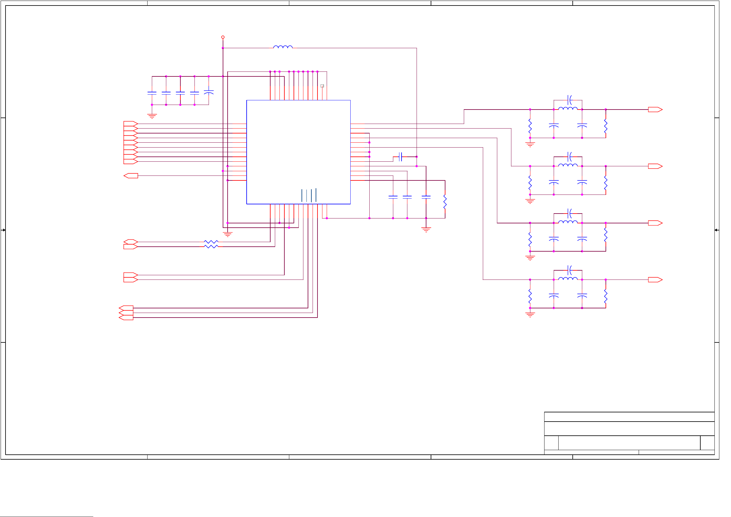
U12
KA7805
3.3V
IN
GND
OUT
1
2
3
E54
C107
104
+
100uF/10
PHILIOS
적용
R123
0
U18A
74HC04
1 2
HYUNDAI 적용(8513)-8513A는 PHILIPS와
PTO[0..7]
LNB_P
R124
5V
CH_STRT
CH_VALID
PHILIOS
적용
R125
4.7K
Q25
KN3904S
같음
POLARITY
0
CH_ERROR
CH_CLK
15KF(2012)
F100
RXE065
CH_RST
CH_ERROR
CH_STRT
CH_VALID
CH_CLK
PTO[0..7]
R131
33KF(2012)]
Q26
DTC114
R132
Q27
KTA1273
3.3V 5V
5.1KF(2012)
R133
R134
20KF(2012)
1 2
3
5
7
9
10
11
12
13
14
15
16
17
18
19
20
NC
R135
300(2012)
4
6
8
heat sink
U19
KA317
123
PTO0
PTO1
PTO2
PTO3
PTO4
PTO5
PTO6
PTO7
H1
방열판
GND와
안됨
C108
104
연결하면
.
24V
5V
R183
100K(2012)
2 2
R126 0
R127 0
SDA
SCL
LNB_DOWN
R184
10K(2012)
Q37
KN3904S
R136
2.7K/3216
C48
104
5V
R137
47(2012)
C49
104
R185
47K(2012)
Q28
DTC114
Q32
LNB_LP LNB_P
KTA1273
LNBP_OFF
8051_LNBP_OFF
R186
4.7K(2012)
Q38
DTC114
R128
4.7K
S5V
R129
10K
1 1
LOOP_CNTL
R130
10K
Q34
KN3904S
Q33
KN3904S
R138
1.8K/3216
Q29
DTC114
R139
10K
Q30
DTC114
Q31
DTC114
R140
4.7K
R141
10K
22KHz
22ON/OFF
UK STRONG
Title
Size Document Number Rev
Date: Sheet
A
B
C
D
QPSK DEMODULATOR
SRT4355 1.1
Custom
of
113Thursday, November 15, 2001
E
Page 17

A
4 4
B
C
D
E
R1
C1
10K
103
3 3
U16
1
2
3
4
5
6
7
8
BSTB+
AUDIOIN
SDA
MODB+
SCL
VIDEOIN
VT+
GND
JP7
RMUP74055WT (
삼성
)
1 2
3 4
5 6
7 8
9 10
2250-10S-DS-T
2.0mm
PITCH
2 2
JP10
1 2
3 4
5 6
7 8
9 10
2250-10S-DS-T
1 1
Title
RF MODULATOR SUB PCB
Size Document Number Rev
A
A
B
C
D
Date: Sheet of
11
E
1.1
11Tuesday, November 20, 2001
Page 18

A
B
C
D
E
S5V
R5
R6
4 4
R7
R8
U1
3
D0
4
D1
7
D2
8
D3
13
D4
3 3
J1
1
2
3
4
5
6
7
8
9
10
11
12
13
2 2
14
S5V
I8051BD0
I8051BD1
I8051BD2
I8051BD3
I8051BD4
I8051BD5
I8051BD6
I8051BD7
14
17
18
1
11
74HCT374DW
U2
3
4
7
8
13
14
17
18
1
11
74HCT374DW
D5
D6
D7
OC
CLK
D0
D1
D2
D3
D4
D5
D6
D7
OC
CLK
Q0
Q1
Q2
Q3
Q4
Q5
Q6
Q7
VCCs
GND
Q0
Q1
Q2
Q3
Q4
Q5
Q6
Q7
VCCs
GND
2
5
6
9
12
15
16
19
20
10
S5V
BC1
104
2
5
6
9
12
15
16
19
S5V
20
10
BC2
104
CON14
D2
1N4001
D4
1N4001
D6
1N4001
1 1
R14
R15
R18
R19 150
R20 150
R21 150
R22 150
R23 150
R24 150
R25 150
R26 150
D1
1N4001
D3
1N4001
D5
1N4001
D8
1N4001
1K
Q3
Q4
KST2222A
1K
1K
1K
KST2222A
Q1
Q2
KST2222A
KST2222A
LED1
1K
1
LED2
1K
1K
Red
LED4
Green
S5V
COM1
2
COM2
3
D-
4
DP1/2+
5
E-
6
COM3
7
DPCOM48DP3-
B-
G-
AC-
DP1/2-
F-
DP3+
16
15
14
13
12
11
10
9
LFD416X
S5V
R27
S1
UP ARROW
KPT1105
S2
DOWN ARROW
KPT1105
S3
LEFT ARROW
KPT1105
S4
RIGHT ARROW
KPT1105
S5
EXIT
KPT1105
S6
SELECT
KPT1105
S7
33
+
EC1
47uF/16V
U3
1
OUT
2
GND
3
VS
HI-M602H3-2
U3
1
GND
2
VS
3
OUT
TSOP1238
TEMIC
(HUNIN)
POWER(STBY)
KPT1105
Title
Size Document Number Rev
B
Date: Sheet of
A
B
C
D
UK STRONG
FRONT CIRCUIT
1.1
1 1Friday, July 27, 200 1
E
Page 19

4. List of Error codes
E001: Tuner Error.
E002: EEPROM Error.
E003: RF Error.
E004: BT864 Error.
E005: L64005 Error.
E006: DRAM Error.
E007: STV0056 Error.
E008: ATuner Error.
5. Trouble Shooting
There may be various reasons for the abnormal operation of the receiver. Check the receiver
according to the procedures shown below.
If the receiver does not work properly after checking it, please contact the dealer. Don’s open
the receiver cover. It may cause a dangerous situation.
5.1. trouble shooting
Symptom Cause Remedy
The display on front
Panel does not light up.
No picture or sound. Wrong connection of
No picture. The receiver can’t
The power cord is
Not plugged in
The Audio/Video output
Of the receiver to TV.
Audio muting.
TV power off.
Receive the signal.
Incorrect values of some
Tuner parameters.
Wrong direction of
the dish
Check that the power cord
Is plugged in to the wall outlet.
Connect the Audio/Video
Output of the receiver to
TV correctly
Press the MUTE button.
Tum TV on.
Check the antenna cable,
Replace the cable, or connect
The cable to the receiver tightly.
Set the values of tuner
Parameters correctly in
System set -up menu.
Check the signal strength
With a spectrum analyzer and
Adjust your dish correctly.
Page 20

The remote controller
Does not working.
5.2. Check point about badness STB
5.2.1. When nothing appears on TV screen(front panel display “0000”)
(1) Check the SMPS’s voltage
- Power Connect(J2) -> pin4, pin5 : 4.75~5.25V
- Power Connect(J2) -> pin6 : 10.2~12.6V
- Power Connect(J2) -> pin3 : 21V~24V
- Power Connect(J2) -> pin1 : 27V ~ 33V
- Power Connect(J2) -> pin7 : 7.5~8.5V
- Power Connect(J2) -> pin9, pin10 : 3.2~3.5V
Action) : If voltage is not normalcy, it change, and measure again SMPS
The batteries of the
Remote controller are
Not inserted or
Exhausted.
Check whether the batteries
Are inserted correctly in your
Remote controller.
Check the batteries, and if
Exhausted, replace the
Batteries of the remote
Controller.
first. Still, SMPS is normalcy if voltage is low.There are
possibility that is badness with parts that use the voltage in
Main Board.
(2) Confirm by Oscilloscope whether 27 MHz break out in R10 and R11.
Action) : if 27Mhz do not break out, X1(27Mhz CRYSTAL), or
U6(74LCX04) change .
(3) ROM Read cycle(Pulse) should be happened continuously through
Oscilloscope at Power off/on in pin 26 of U2(39vf800A Flash ROM).
(If U2's pin 26 is 3.3V by Voltage Meter, it is normalcy)
Action) : if U2- pin26 is measured (0V ~ 2V) by Voltage Meter,
U2(39VF800A FLASH ROM) change, still, change U1(L64108
CPU) if do not act.
Page 21

(4) Flash-Rom of Start Control Signal uses reset, chip-Select
RESET --à
Check Point : U2(12pin)
CE --à
Check Pint : U2(26 pin)
Action) : If the flash-Rom(U2) not operation. , must be Checking chip-select
pin from L64108. Replacement of part is required. Because Reset and
Chip-Select signal is not Booting.
Also , Checking soldering or Chip is consider flash-rom and CPU
Where are replace of component Part, and Check the insertion of
part
(5) Confirm that Message is displayed when interlink STB and PC by RS232
CABLE and did Power off/on
Execute Hyper terminal in PC and do together Setup with next time
Baud Rate: 115,200bps.
Data bit:8 bit
Parity bit :none
Stop bit :1
Control: none
1) When Message is not displayed:
1. Do AC Power put on in state that click Menu and Select key
simultaneously after AC power put off, (method by boot
mode Booting) Still, if any message is not displayed, it
changes U2(39VF800A flash ROM)
Page 22

.
2. if “starting boot” message is displayed, Do Download again
by suitable Firmware to model.
3. Do STB Power off/on after Download is completed.
4. If screen is displayed, it does FACTORY RESET necessarily.
2) When Message is displayed:
(Message can be different according to Firmware Version)
Set ACLK <32000>
PHILIPS TDA8044 connected
IT520S SET -TOP BOX MONITOR v1.10 BY INTEGRA TELECOM
Nov 02 2000,23:35:35, http: www.integra.co.kr
>size of sysconfig=140
flash pattern(ffff)
flash pattern(ffff)
flash pattern(ffff)
PHILIPS TDA8044 connected
Enable AV Interrupts
launch OSD
launch OSD 3
Set ACLK <3>
launch OSD 4
launch OSD 4.5
launch OSD 5
intr EN end[D:0][AV:3c00]
RegValue23=3
AVO:OSD Initialized
AV decoder and OSD initialized
1. When “I2C ERROR” ,”EEPROM ERROR”,”TUNER CONNECT
FAIL” message happens After AC POWER OFF, measuring
resistance between U1's pin 156 and GND, pin 155 and GND, if
it is measured (20ohm ~ 0 ohm), L64108 ( CPU ) must change.
2. When “EEPROM ERROR” Message happens
Page 23

U4 : EEPROM(24C64) change
3. When “Tuner connect Fail” Message happens
If POWER supplied to Tuner is normalcy, Tuner must change.
4. When “ FLUSH DRAM ” Message happens
U7(L64005) and U8(KM416S1020) Re- soldering do, and
change U7(L64005) if is happened again.
5. Normal Message as being displayed, change MICOM if TV screen
does not come
5.2.2. When “NO SIGNAL” message appears
(1) U19:(KA317(Regulator))- > pin 3 : 21V~24V
U19:(KA317(Regulator))-> pin 2 : 13V /18V
If confirm that voltage is measured and is not measured, U19 change
Action) : When U19's(KA317) input voltage is low, do you change SMPS,
do U19 Voltage Line check in SMPS if change SMPS and is
low.
(2) Measure by Voltage Meter(Oscilloscope) whether VERTICAL(13Volt) or
HORIZONTAL(18Volt), 22KHz(ON/OFF) is displayed normally measuring
voltage of F100's Lead(or Tuner LNB OUT PORT) when do SCAN
satellite in INSTALL MENU.
(LNB supply voltage check)
(3) When LNB voltage(13V/18V) is not displayed, it changes Q27(TR:kta1273) if
13V/18V is displayed measuring Q27's(TR:kta1273) Emitter monad by
Voltage Meter and measure whether 13V/18V is displayed in F100(Poly
Switch)
Action) : If mania is happened to F100 or Q27 after shift Tuner shift
(4) Voltage measurement supplied to TUNER
1. L13(Coil) : about 5V,
Page 24

L14(Coil): about 28V ,
U12(Regulator)-Pin 3 : about 5V
(E54(+)Elect Cap ) : 3.3V
Action) : If voltage is normalcy TUNER change .
2. U12(Regulator)-Pin3 : 3V~ 0V
Action) : If it is 100 ohm lows, doing AC POWER OFF and measure
U12's(Regulator) 3Pin and resistance between GND,
Tuner change
(5) Check I2C Control Signal
Action) : if Voltage is drop SCL as well as SDA. “ No Signal ” message will
be Display at TV Screen. therefore each of part check have to
SCL with SDA of Voltage 3.2 ~3.5V. Check the install chip-position
and short of solder, cold solder, etc. Where are replace of
component Part, Check the insertion of part
SCL --à
SDA --à
(6) Changing SMPS test
(7) Try scan a gain after Factory reset
Action) : Do U2(39VF800A Flash ROM) and U1(L64108 CPU) Re- solder
if “Wait to Reset setting” Message comes continually when did
Page 25

Factory Reset. Still, change U2(39VF800A Flash ROM) if do not
become.
5.2.3. “CI CARD INITIALIZING NOW….” Message becomes Display continually on screen and
when Menu transfer is slow Firmware again Download do .
5.2.4. When do not act whether FRONT 7-SEGMENT(DISPLAY) acts strangely
(6) Change FRONT PANEL
(7) Change MICOM(U10) (AT89C51)
U10 : Confirm by SCOPE whether 11.0592 MHzs break out in pin 21
(8) Confirm by SCOPE whether 11.0592 MHzs break out in U10- pin 20, 21
5.25. When VIDEO screen gets into Scratch occurrence
(1) If scratch is happened on Video screen and Audio noise or stop phenomenon
is happened Tuner change .
(2) Audio is normalcy and if scratch is happened Video screen U7 : (L64005)
U8 : (km416S1020 sdram) change
(3) When Video Color is badness, U11 : (BT864) change.
(4) After Power ON, when that stop screen phenomenon happens U13 : (AKM4323) change
(5) Video Filter from Bt864A (Digtal Video Encoder)
Action) : If the Color signal is not operation. Shoud be Checking
CVBS --à
43pin(SYSCLK) 27Mhz Of U11 and VCC(3.3V) if you have
checking, If No problem. Check the install chip -poistion and short of
solder, cold solder, etc. Where are replace of component Part, Check
the insertion of part
(LOW active) RESET --à
Page 26

RED --à
GREEN --à
BLUE --à
Page 27

Page 28

6. Materials list
6.1 Main PCB materials list
cc Quantity Reference Part Number VENDOR
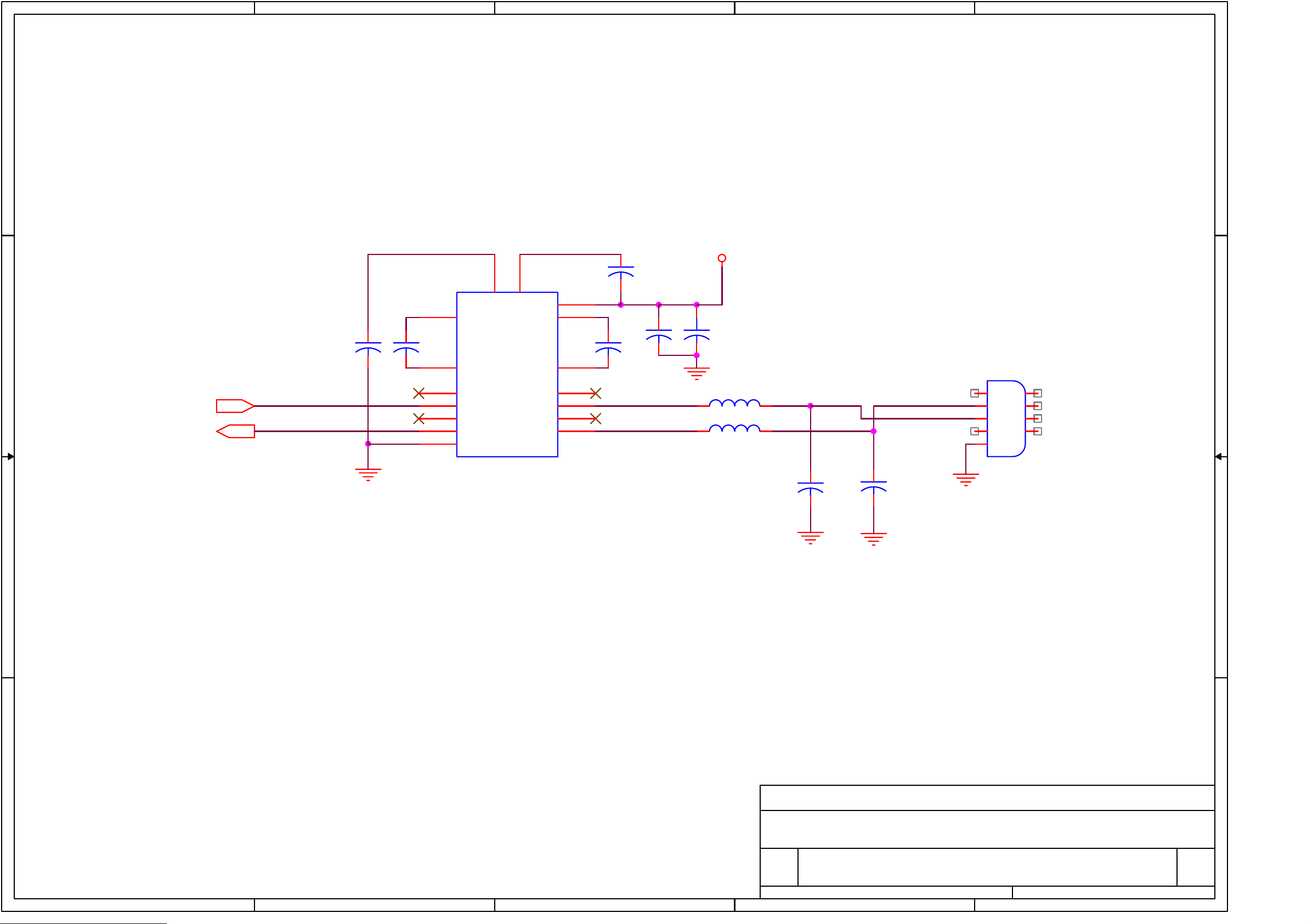
1 1 PCB-MAIN ; IT612_R1.8 VER 1.8, 2Layer
2 3 BD1,BD2,L15 CORE-FERRITE BEAD ; FCM2012C-101,100ohm TAI-Tech
3 7 BD6,BD9,BD24,BD3,BD4,BD5,BD7 CORE-FERRITE BEAD ; SMB403025 TAI-Tech
4 4 L4,L5,L6,L7 INDUCTOR-SMD ; FCI1608-1R8K,1608 SIZE TAI-Tech
5 7 L1,L2,L3,L10,L12,L13,L14 INDUCTOR-SMD ; 10uH, 10%, 2012 TAI-Tech
6 20 R8,R9,R16,R23,R35, R-CHIP ; 1Kohm, 5%, 1/16W, DA, TP, 1608 HAN RYUK
R84,R90,R96,R98,R100,
R103,R107,R116,R122,R148,
R149,R162,R173,R176,R177
7 28 R13,R17,R19,R20,R27,R32, R-CHIP ; 4.7Kohm, 5%, 1/16W, DA, TP, 1608 HAN RYUK
R33,R34,R49,R50,R57,R60,R125,
R128,R140,R144,R145,R146,
R147,R150,R151,R152,R153,
R156,R159,R167,R142,R143
8 12 R36,R85,R89,R129, R-CHIP ; 10Kohm, 5%, 1/16W, DA, TP, 1608 HAN RYUK
R130,R139,R141,R171,R172,
R175,R178,R179
9 2 R163,R164 R-CHIP ; 100ohm, 5%, 1/16W, DA, TP, 1608 HAN RYUK
10 3 R14,R15,R51 R-CHIP ; 3.3Kohm, 5%, 1/16W, DA, TP, 1608 HAN RYUK
11 1 R18 R-CHIP ; 10ohm, 5%, 1/16W, DA, TP, 1608 HAN RYUK
12 11 R21,R22,R24,R37,R38,R55, R-CHIP ; 0ohm, 5%, 1/16W, DA, TP, 1608 HAN RYUK
R123,R124,R126,R127,R166
13 1 R28 R-CHIP ; 150ohm, 5%, 1/16W, DA, TP, 1608 HAN RYUK
14 2 R30,R29 R-CHIP ; 18ohm, 5%, 1/16W, DA, TP, 1608 HAN RYUK
15 1 R31 R-CHIP ; 200ohm, 5%, 1/16W, DA, TP, 1608 HAN RYUK
16 15 R39,R97,R99,R104,R108,R115, R_CHIP ;75ohm, 1%, 1/16W, DA, TP, 1608 HAN RYUK
R40,R41,R43,R44,R45,R46,R47,R42,R95
17 4 R102,R168,R169,R192 R-CHIP ; 6.8Kohm, 5%, 1/16W, DA, TP, 1608 HAN RYUK
18 5 R3,R4,R161,R160,R121 R-CHIP ; 33ohm, 5%, 1/16W, DA, TP, 1608 HAN RYUK
19 1 R131 R-CHIP ; 15Kohm, 1%, 1/10W, DA, TP, 2012 HAN RYUK
20 1 R132 R-CHIP ; 33Kohm, 1%, 1/10W, DA, TP, 2012 HAN RYUK
21 1 R133 R-CHIP ; 5.1Kohm, 1%, 1/10W, DA, TP, 2012 HAN RYUK
22 1 R134 R-CHIP ; 20Kohm, 1%, 1/10W, DA, TP, 2012 HAN RYUK
23 1 R135 R-CHIP ; 300ohm, 5%, 1/10W, DA, TP, 2012 HAN RYUK
24 1 R137 R-CHIP ; 47ohm, 5%, 1/10W, DA, TP, 2012 HAN RYUK
Page 29

25 1 R136 R-CHIP ; 2.7Kohm, 5%, 1/8W, DA, TP, 3216 HAN RYUK
26 1 R138 R-CHIP ; 1.8Kohm, 5%, 1/8W, DA, TP, 3216 HAN RYUK
27 1 R12 R_CHIP ;16.9Kohm,1%,1/16W,DA,TP,1608 HAN RYUK
28 6 R93,R94,R109,R110,R111,R112 R-CHIP ; 560ohm, 5%, 1/16W, DA, TP, 1608 HAN RYUK
29 3 R58,R52,R53 R-CHIP ; 1.2Kohm, 5%, 1/16W, DA, TP, 1608 HAN RYUK
30 2 R101,R191 R-CHIP ; 20Kohm, 5%, 1/16W, DA, TP, 1608 HAN RYUK
31 2 R113,R184 R-CHIP ; 10Kohm, 5%, 1/10W, DA, TP, 2012 HAN RYUK
32 1 R185 R-CHIP ; 47Kohm, 5%, 1/10W, DA, TP, 2012 HAN RYUK
33 2 R1,R186 R-CHIP ; 4.7Kohm, 5%, 1/10W, DA, TP, 2012 HAN RYUK
34 1 R183 R-CHIP ; 100Kohm, 5%, 1/10W, DA, TP, 2012 HAN RYUK
35 1 R92 R-CHIP ; 100ohm, 5%, 1/10W, DA, TP, 2012 HAN RYUK
36 1 R182 R-CHIP ; 0ohm, 5%, 1/10W, DA, TP, 2012 HAN RYUK
37 2 R154,R157 R-CHIP ; 470ohm, 5%, 1/16W, DA, TP, 1608 HAN RYUK
38 1 R2 R-CHIP ; 620ohm, 5%, 1/16W, DA, TP, 1608 HAN RYUK
39 1 R5 R-CHIP ; 6.2Kohm, 1%, 1/16W, DA, TP, 1608 HAN RYUK
40 1 R6 R-CHIP ; 3.3Kohm, 5%, 1/10W, DA, TP, 2012 HAN RYUK
41 1 R91 R-CHIP ; 75ohm, 5%, 1/16W, DA, TP, 1608 HAN RYUK
42 5 R114,R117,R118,R119,R120 R-CHIP ; 75ohm, 1%, 1/10W, DA, TP, 2012 HAN RYUK
43 4 RA2,RA4,RA9,RA24, R-NETWORK ; 10Kohm, 5%, 1/16W, L, CHIP, 4P, TP, 1608 HAN RYUK
44 1 RA1 R-NETWORK ; 1Kohm, 5%, 1/16W, L, CHIP, 4P, TP, 1608 HAN RYUK
45 9 RA3,RA8,RA13,RA14,RA19, R-NETWORK ; 4.7Kohm, 5%, 1/16W, L, CHIP, 4P, TP, 1608 HAN RYUK
RA20,RA23,RA15,RA16,
46 5 RA5,RA6,RA7,RA17,RA18, R-NETWORK ; 100ohm, 5%, 1/16W, L, CHIP, 4P, TP, 1608 HAN RYUK
47 3 RA10,RA11,RA12 R-NETWORK ; 33ohm, 5%, 1/16W, L, CHIP, 4P, TP, 1608 HAN RYUK
48 86 C6,C9,C14,C17,C18,C19, C-CERAMIC, CHIP ; 100nF, +80-20%, 50V, Y5V, TP,1608 SAMWHA
C20,C27,C28,C29,C30,C44,
C45,C46,C47,C48,C49,C60,C61,
C62,C63,C64,C65,C66,C67,
C68,C69,C70,C71,C72,C74,
C75,C76,C77,C78,C79,C80,
C81,C82,C83,C84,C85,C86,
C87,C88,C89,C90,C91,C92,
C93,C94,C95,C96,C97,C98,
C99,C100,C101,C102,C103,
C104,C105,C106,C107,C108,
C109,C110,C111,C112,C113,
C114,C115,C116,C117,C118,
C119,C120,C121,C122,C123,
C124,C125,C126,C135,C136,C137
49 5 C8,C32,C35,C38,C41 C-CERAMIC CHIP ; 22pF, 5%, 50V, NPO, TP, 1608 SAMWHA
50 1 C15 C-CERAMIC, CHIP ; 20pF, 5%, 50V, NPO, TP, 1608 SAMWHA
51 2 C24,C23 C-CERAMIC, CHIP ; 18pF, 5%, 50V, NPO, TP, 1608 SAMWHA
Page 30

52 4 C31,C34,C37,C40 C-CERAMIC, CHIP ; 270pF, 5%, 50V, NPO, TP, 1608 SAMWHA
53 4 C33,C36,C39,C42 C-CERAMIC, CHIP ; 330pF, 5%, 50V, NPO, TP, 1608 SAMWHA
54 8 C127,C128,C129,C130,C131, C-CERAMIC, CHIP ; 470nF, +80-20%, 16V, Y5V, TP, 2012 SAMWHA
C132,C133,C134
55 5 C10,C13,C16,C21,C22 C-CERAMIC, CHIP ; 1000pF, 5%, 50V, X7R, TP, 1608 SAMWHA
56 1 C7 C-CERAMIC, CHIP ; 1500pF, 10%, 50V, X7R, TP, 1608 SAMWHA
57 1 C1 C-CERAMIC, CHIP ; 1uF, +80-20%, 16V, Y5V, TP, 1608 SAMWHA
58 1 C2 C-CERAMIC, CHIP ; 51pF, 5%, 50V, COG, TP, 1608 SAMWHA
59 2 C11,C12 C-CERAMIC, CHIP ; 10nF, 10%, 50V, X7R, TP,1608 SAMWHA
60 2 D1,D2 DIODE-SWITCHING ; RLS4148,100V,450mA,LL- Rohm
61 4 Q33,Q34,Q37,Q513 TR-SMALL SIGNAL ; KST3904-MTF,NPN,-60V,- SAMSUNG
62 11 Q4,Q5,Q7,Q9,Q10,Q26,Q28, TR-DIGITAL ; DTC114EKA,NPN,100mA,200mW,SC-59 Rohm
Q29,Q30,Q31,Q38
63 1 U1 IC-MICROPROCESSOR ; L64108-54 MIPS/XPORT,240PIN,QFP LSI logic
64 1 U2 IC-FLASH MEMORY ; SST39VF800A-90-4C-EK,1MX8BIT,TSOP,48P,3.3V SST
65 1 U3 IC-DRAM ; KM416V1204CJ-6 or 7,1MX16BIT,SOJ,42P,3.3V SAMSUNG
66 1 U8 IC-SDRAM ; KM416S1020CT-G7 or 8 or 10,512KX16BIT,TSOP,50P,3.3V SAMSUNG
67 1 U4 IC-EEPROM ; AT24C64N-10SC-2.7,64KBYTE,SOIC,8P,3.3V ATMEL
68 10 U21,U22,U25,U26,U27, IC-CMOS LOGIC ; MM74HCT244MTC Fairchild
U28,U29,U30,U31,U32
69 1 U20 IC-CMOS LOGIC ; MM74HCT245MTC Fairchild
70 1 U6 IC-CMOS LOGIC ; 74LCX04M,LOW VOLTAGE HEX INVERTER,SOP,14P Fairchild
71 1 U23 IC-PLD ; EPM3032ALC44-10 (PLCC) ALTERA
72 1 U11 IC-VIDEO ENCODER ; BT864AKRF,NTSC/PAL DIGITAL VIDEO ENCODER,PQFP,52P Rockwell
73 1 U13 IC-D/A CONVERTER ; AK4323VF-E2,20BIT,VSOP,24P AKM
74 1 U15 IC-AUDIO/VIDEO SWITCH ; CXA2126Q Sony
75 1 U9 IC-TRANSMITTER/RECEIVER ; SP232ECN,SOIC,16P SIPEX
76 1 U5 IC-RESET ; DS1811-10, SOT-23,3P ILSSAN
77 1 U10 socket SOCKET-IC ; 3262-44-T,PLCC ILSSAN
78 1 U7 IC-A/V DECODER ; L64005F LSI logic
Item Quantity Reference Part Number VENDOR
1 2 E8,E9 C-AL ; 47uF/50V-6.3*11*5, FORMING CUT TYPE SAMWHA
2 1 E53 C-AL ; 220uF/16V-8*11.5*5, FORMING CUT TYPE SAMWHA
3 3 E17,E12,E25 C-AL ; 4.7uF/50V-5*11*5, FORMING CUT TYPE SAMWHA
4 3 E24,E41,E52 C-AL ; 10uF/50V-5*11*5, FORMING CUT TYPE SAMWHA
5 3 E11,E57,E54 C-AL ; 100uF/16V-6.3*11*5, FORMING CUT TYPE SAMWHA
6 4 E7,E16,E40,E51 C-AL ; 47uF/25V-5*11*5, FORMING CUT TYPE SAMWHA
7 20 E1,E2,E3,E4 C-AL ; 10uF/25V-5*7*5, FORMING CUT TYPE SAMWHA
E5,E6,E13,E14,E15,E18,E21,E23,E39,
E43,E44,E45,E47,E48,E49,E50
8 2 E27,E35 C-AL ; 22uF/16V-5*7*5, FORMING CUT TYPE SAMWHA
Page 31

9 6 E31,E29,E33,E34,E55,E56 C-AL ; 1uF/50V-5*11*5,FORMING CUT TYPE SAMWHA
10 1 E10 C-AL ; 470uF/10V-8*11.5*5, FORMING CUT TYPE SAMWHA
11 1 E59 C-AL ; 1000uF/10V-10*16*5, STRAIGHT CUT TYPE SAMWHA
12 8 Q16,Q17,Q18,Q19,Q20,Q21,Q22,Q23 TR-SMALL SIGNAL ; 2N3904 TO-92 단일 PKG,NPN,60V,40V,200mA,1.5W,TO-92 SAMSUNG
13 6 Q11,Q27,Q32,Q35,Q36,Q512 TR-POWER ; KTA1273Y,PNP,-30V,-30V,-2A,1W,TO-92L KEC
14 1 F100 CIRCUIT-BREAKER ; RXE065,60Vrms,DIP,40A MANSUNG
15 2 U14,U12 IC-VOLTAGE REGULATOR ; KA7805AT(TU),TO-220,3P Fairchild
16 1 U19 IC-VOLTAGE REGULATOR ; KA317M(TU),TO-220,3P Fairchild
17 2 Q8,Q3 FET-GaAs ; IRFZ34N(A), Advanced Power Mos FET Fairchild
18 1 U39 OSCILLATOR-VCXO ; 13T-63AP,27MHz-3.3V KONY
19 1 X2 CRYSTAL-UNIT ; 11.0592MHZ,0.0030%,HC-49/S,18pF,60ohm,BK SHINYOUNG
20 1 S1 JACK-SCART ; 2203-42ST(-A-),DUAL,42P,RIGHT ANGLE TYPE ILSSAN
21 1 J4 CONNECTOR-SOCKET ; 3302-09S-AFS-0,9P,RIGHT ANGLE SOKET TYPE ILSSAN
22 1 J2 CONNECTOR-HEADER ; 5267-11,2WALL, 11P, 1R, 2.5mm, STRAIGHT MOLEX
23 1 JP8 CONNECTOR-HEADER ; 2110-DS 10-G(100MIL),2.54mm PIN HEADER (straight dual row) ILSSAN
24 1 P200,P201 CONNECTOR-PCMCI ; P1T2B1393,Long eject,2 층 OTAX
25 1 J5 JACK-RCA ; JS0401315N,4P,6MM DAE RYUNG
26 1 J1 CONNECTOR-WAFER ; 14PIN,SW0500-14,FRONT MOLEX
27 2 JP6,JP11 PLUG-CONNECTOR ; 2250-10P-DS-T ILSSAN
28 1 U17 FREQ-MODULE ; TBMU 30311 IMP,950~2150MHZ SAMSUNG
29 1 H1 HEAT SINK ; PRES B-TYPE,SIL,AL6063,30*15*22.5 INSUNG
30 3 Q1,Q2,Q6 TR-POWER ; KSB772-Y, PNP, 10W, T0-126, 160 Fairchild
Item Quantity Reference Part Number VENDOR
1 1 ASS'Y SCREW ; TT2,BIN(+),WTH3X6
2 1 ASS'Y SMPS ; P-126A, NO POSITIONER INSUNG
3 1 ASS'Y CABLE-POWER ; KKJ640 YOUNGSHIM
4 1 U10 IC-MICROCONTROLLER ; AT89C51-12/16/20/24JC(I) (PLCC) ATMEL
Item Quantity Reference Part Number
1 1
2 1 U16 RF-MODULATOR ; RMUP74055WT SAMSUNG
3 2 JP7,JP10 CONNECTOR-SOCKET ; 2250-10S-DS-T ILSSAN
SUB PCB ; IT612_R1.3 VER 1.3, 1Layer
VENDOR
Page 32

6.2 Front PCB materials list
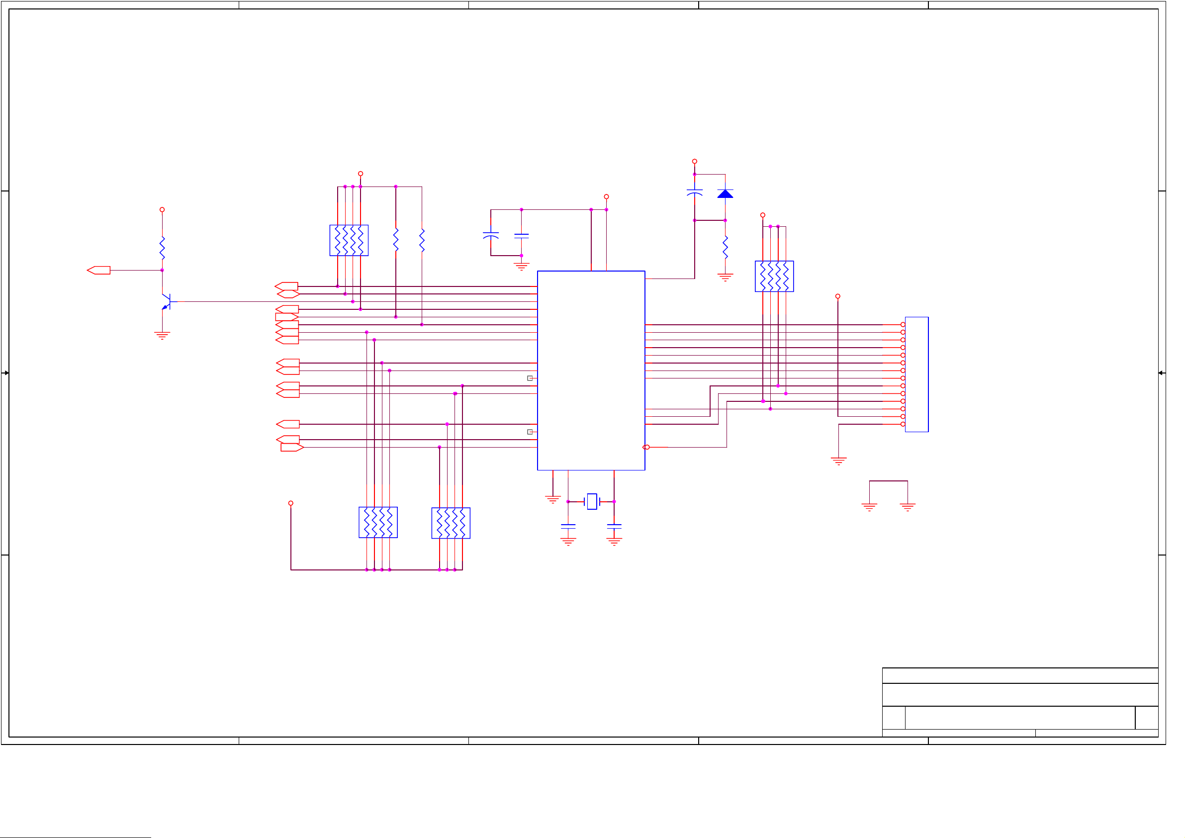
Item Quantity Reference Part Number Vendor
1 2 BC1,BC2 CR051BX7R104Z500R SAMWHA
2 7 D1,D2,D3,D4,D5,D6,D8 1N4001 PHILIPS
3 1 J1 14P 162020 MOLEX
4 1 FOUR DIGIT DISPLAY LFD4162-10/SP8 LIGITEK
5 1 FOUR DIGIT DISPLAY support support : 10mm
6 1 LED2 LH3330 LIGITEK
7 1 LED4 LG3330 LIGITEK
8 2 LED support support : 7mm
9 4 Q1,Q2,Q3,Q4 2N2222A SAMSUNG
10 7 R5,R6,R7,R8,R14,R15,R18 RNL 1/6 102 JT-52 HAN RYUK
11 1 R27 RNL 1/6 330 JT-52 HAN RYUK
12 8 R19,R20,R21,R22,R23,R24, RNL 1/6 151 JT-52 HAN RYUK
R25,R26
13 1 EC1
14 7 S1,S2,S3,S4,S5,S6,S7 KPT-1115A KYUNG IN
15 2 U1,U2 74HCT374N TI,ST,LG
16 1 U3 TSOP1238
17 1 U3 support support : 10mm
18 1 front PCB ITF612F-R1.2
RSS/TS 25-47 5*11 2.5
DAEWOO
7. Software download instructions(OTA and PC download)
7.1 Program Download
Page 33

Firmware download
You can download firmware to receiver
- Press “BROWE” button to select firmware (ELF) to downloading.
- After selecting firmware, you can start downloading by pressing “START” button.
- You can see progressing bar while downloading
- The receiver will automatically restart when downloading is finished.
Channel Information upload
You can save channel information of receiver to PC file by using this function
- You have to select a file to save in PC by pressing “BROWSE” button.
- Press “START” button to start uploading
Channel Information download
You can download channel information saved above to receiver
- You have to select a file to download to receiver by pressing “BROWSE” button.
- Press “START” button to start downloading
7.2 System Upgrade
If there is a new version of software available for your receiver, you are able to download it
Page 34

automatically via the satellite signal of ASTRA 19.2 East.
1. Please wait while your receiver is checking if your software version is the newest one available.
2. If you already have the newest version noting will happen, and you can leave the menu. When you
need the newest version software, the receiver will automatically download that version from the
satellite signal. After the download is finished, your screen will turn green for a few seconds
while the receiver is re-booting.
When the screen is back is to normal, you can leave the menu.
Tips : Do not turn off your receiver while you are downloading new software.
Be sure that your receiver is connected to the satellite signal of ASTRA 19.2 East.
7.3 SRT4355 U23(EPM3032ALC44-10) programming method
1. MAX+plus II icon double clock
Page 35

2. MAX+plus II menu clock -> “Programmer” clock on sub menu
Page 36

3. “Option” -> “Hardware setup” -> ByteBlaster(MV)
Page 37

“File” on main menu à “Select Programming File” -> select programming file(srt4355.pof) in
directory
4. select “Program” -> down loading start
Page 38
5. STB power off or cable not connected, if it have error message
6. if you want to check device check sum, select “Examine”
Page 39

2pin
2pin
8. Specification of required cables for software download
8.1 PC Download Cable
S
E
T
9PIN (E -MAIL) 9PIN (P-MAIL)
1pin
5pin
1pin
P
C
5pin
Page 40

8.2 U23 Download Cable
 Loading...