

Page 1

Gear limit switch
EKM-0119
EN-GB
Type series HGE
Document No.: 152-00000 F
Date: 10/2017
Mounting/operating instructions
Stromag GmbH
Hansastraße 120
D-59425 Unna
Tel.: +49 (0) 2303 102-0
Fax: +49 (0) 2303 102-201
www.stromag.com
[email protected]
Page 2

Contents
1 Introduction................................................................................................................................1
1.1 About this documentation........................................................................................................................... 1
1.1.1 Target group............................................................................................................................................ 1
1.1.2 Use/storage............................................................................................................................................. 1
1.2 Using the documentation correctly............................................................................................................. 2
1.2.1 Text formats.............................................................................................................................................2
1.2.2 Definition of terms....................................................................................................................................2
1.3 Warranty and liability.................................................................................................................................. 3
1.3.1 Guarantee................................................................................................................................................3
1.3.2 Copyright................................................................................................................................................. 3
2 For your safety...........................................................................................................................3
2.1 Safety concept of the documentation......................................................................................................... 3
2.2 Required personnel qualifications...............................................................................................................4
2.3 Intended use...............................................................................................................................................4
2.3.1 Application limits......................................................................................................................................4
2.3.2 Approvals.................................................................................................................................................4
2.4 Non-intended use....................................................................................................................................... 4
2.5 EC Declaration of Conformity..................................................................................................................... 4
2.5.1 Standards applied....................................................................................................................................5
2.6 Possible residual risks................................................................................................................................ 5
2.6.1 Mechanical dangers.................................................................................................................................5
2.6.2 Thermal dangers......................................................................................................................................5
2.6.3 Electrical danger......................................................................................................................................5
2.7 Safety symbols/pictograms in the documentation...................................................................................... 5
2.7.1 Warning symbols..................................................................................................................................... 5
2.7.2 Hazard classifications..............................................................................................................................5
2.7.3 Mandatory symbols..................................................................................................................................6
2.7.4 Note......................................................................................................................................................... 6
2.7.5 Environmental protection/recycling..........................................................................................................6
2.8 GTES safety devices.................................................................................................................................. 6
2.9 Safety symbols/pictograms on the GTES................................................................................................... 7
2.10 Wear personal protective equipment..........................................................................................................7
2.11 Basic responsibilities of the operator and personnel.................................................................................. 7
2.12 Safe handling of rotating components........................................................................................................ 7
2.13 Safe handling with hot surfaces..................................................................................................................7
2.14 Safe handling with electrical hazards......................................................................................................... 7
2.14.1 Responsibility of the operator.................................................................................................................. 8
2.14.2 Applying the five safety rules...................................................................................................................8
2.14.3 IP protection type and class.....................................................................................................................8
2.14.4 Electromagnetic compatibility.................................................................................................................. 8
2.15 Environmental protection............................................................................................................................8
3 Transport and storage.............................................................................................................. 9
3.1 Transport.................................................................................................................................................... 9
3.1.1 Unpacking................................................................................................................................................9
3.2 Scope of delivery........................................................................................................................................ 9
3.2.1 Pre-mounting condition............................................................................................................................9
3.3 Storage..................................................................................................................................................... 10
4 Technical specifications......................................................................................................... 10
4.1 Product data............................................................................................................................................. 10
4.1.1 Dimensions............................................................................................................................................10
4.1.2 Mechanical specifications......................................................................................................................10
4.1.3 General information............................................................................................................................... 13
4.1.4 Specific electrical values and position of the contact.............................................................................13
4.1.5 Contact positions................................................................................................................................... 16
II
Mounting/operating instructions Gear limit switch Type series HGE • No. 152-00000 F • 10/2017
Page 3

4.1.6 Type code..............................................................................................................................................17
4.2 Dimensional drawing................................................................................................................................ 18
4.3 Marking on the product.............................................................................................................................18
5 Construction and function......................................................................................................19
5.1 Switch sizes..............................................................................................................................................19
5.2 Component designations..........................................................................................................................20
5.3 Design, task and function of the assembly groups................................................................................... 20
5.3.1 Electrical connections............................................................................................................................21
5.3.2 Mounting position...................................................................................................................................21
5.3.3 Drive flange............................................................................................................................................22
5.4 Optional equipment available................................................................................................................... 22
5.4.1 Design with additional potentiometer.....................................................................................................22
5.4.2 Adjustment of the potentiometer with drive via a torsionally-stiff coupling.............................................23
5.4.3 Adjustment of the potentiometer when the drive is over gear wheels................................................... 23
5.4.4 Design with heating resistor...................................................................................................................24
6 Assembly..................................................................................................................................25
6.1 Special safety guidelines.......................................................................................................................... 25
6.2 Conditions for assembly and fixing...........................................................................................................25
6.2.1 Special tools.......................................................................................................................................... 25
6.2.2 Assembly precision................................................................................................................................25
6.2.3 Tightening torques.................................................................................................................................26
6.2.4 Requirements for the connecting components...................................................................................... 26
6.3 Assembly mechanics................................................................................................................................26
6.3.1 Assembly of the housing (design without flange).................................................................................. 26
6.3.2 Assembly of the housing (design with flange)....................................................................................... 27
6.4 Electrical assembly...................................................................................................................................27
6.4.1 Insert the connection cable into the GTES............................................................................................ 28
6.4.2 Connect the contacts.............................................................................................................................28
6.4.3 Connect the heating...............................................................................................................................28
6.4.4 Connect the earth conductor................................................................................................................. 29
6.5 Connection diagrams................................................................................................................................29
6.5.1 Electrics................................................................................................................................................. 29
6.6 Switching point adjustment.......................................................................................................................29
6.6.1 Normal adjustment "V50".......................................................................................................................31
6.6.2 Fine adjustment “FV50”......................................................................................................................... 32
6.6.3 Double fine adjustment "DFV"............................................................................................................... 33
6.6.4 Normal adjustment "V70".......................................................................................................................34
6.6.5 Fine adjustment “FV70”......................................................................................................................... 34
6.6.6 Block adjustment "BV"........................................................................................................................... 35
6.6.7 Block adjustment "BFV".........................................................................................................................36
6.7 Mount the cover........................................................................................................................................37
6.8 Correct disposal/recycling of operating and auxiliary materials................................................................37
7 Operation..................................................................................................................................37
7.1 Special safety guidelines.......................................................................................................................... 37
7.2 Initial commissioning.................................................................................................................................37
7.3 Use........................................................................................................................................................... 37
7.3.1 Operating conditions..............................................................................................................................38
7.4 Recommissioning..................................................................................................................................... 38
7.5 Decommissioning..................................................................................................................................... 38
7.5.1 Temporary decommissioning.................................................................................................................38
7.5.2 Final decommissioning.......................................................................................................................... 38
8 Maintenance and inspections................................................................................................ 38
8.1 Special safety guidelines.......................................................................................................................... 38
8.2 Measures for environmental protection.................................................................................................... 38
8.3 General points.......................................................................................................................................... 38
8.4 Maintenance and inspection intervals.......................................................................................................38
Mounting/operating instructions Gear limit switch Type series HGE • No. 152-00000 F • 10/2017
III
Page 4

8.4.1 Cleaning.................................................................................................................................................39
9 Troubleshooting...................................................................................................................... 39
9.1 Operational issues and their solutions......................................................................................................39
10 Disassembly.............................................................................................................................39
10.1 Special safety guidelines.......................................................................................................................... 39
10.2 Removing the GTES.................................................................................................................................39
10.3 Final decommissioning............................................................................................................................. 39
11 Ordering spare parts............................................................................................................... 40
11.1 Data for ordering spare parts....................................................................................................................40
11.2 Service address........................................................................................................................................40
12 EC Declaration of Conformity................................................................................................ 41
IV
Mounting/operating instructions Gear limit switch Type series HGE • No. 152-00000 F • 10/2017
Page 5

1 Introduction
1.1 About this documentation
Stromag GmbH, hereafter referred to as Stromag, recommends referring to the dimensional drawing for technical details such as dimensions, weights in kg, tolerances, tightening torques and operating material required for
assembly, such as safety devices and lubricants.
Should this information be necessary during assembly, a corresponding point in these mounting/operating instructions will be referenced on the dimensional drawing.
A dimensional drawing is supplied as a separate document and can be requested additionally from Stromag
Customer Care, see section 4.2. For this, the information on ordering spare parts is required, see section 11.1.
For the purpose of simplification, the following designations are used in the mounting/operating instructions.
• Mounting/operating instructions will be referred to as Documentation in the following.
• The gear limit switch HGE, will be referred to as GTES in the following.
This documentation makes it easier for the operator to familiarise himself with the GTES and to use it for its
intended application.
This documentation covers various GTES designs. The figures used are partly by way of example only. The
specific design of the supplied GTES is shown in the dimensional drawing, see section 4.2.
The documentation contains important instructions on how to operate the GTES safely, properly and economically. Observing the documentation helps to avoid dangers, to reduce repair costs and down times and to increase the reliability as well as the operating life of the GTES. Read the documentation carefully and thoroughly.
1.1.1 Target group
The documentation is limited to use by qualified as well as trained personnel.
The documentation must be read and applied by every person that is assigned with performing at least one of
the following tasks:
• transport
• assembly
• use
• maintenance and inspections
• troubleshooting
• disassembly
• disposal of operating and auxiliary materials
1.1.2 Use/storage
This documentation must always be kept to hand at the operation location of the GTES. The documentation
must then be integrated into the overall documentation of the machine and into the safety concept.
When selling the GTES, the documentation must also be passed on.
Mounting/operating instructions Gear limit switch Type series HGE • No. 152-00000 F • 10/2017
1
Page 6

1.2 Using the documentation correctly
1.2.1 Text formats
The following symbols/figures are used for special text positions in the documentation:
Symbol Explanation
● Indicates bulleted lists
— Indicates subordinate bulleted lists
► Indicates handling instructions and information in the safety guidelines
1. 2. 3. et seq. Indicates work steps
Fig. 1, 2, 3, et seq. Numbering of figures
A, B, C, et seq. Indicates areas in the figures
a, b, c, et seq. Indicates dimensions
Indicates position numbers in the figure
(1)/(2)/(3) Indicates position numbers in the text
1.2.2 Definition of terms
Operator
The operator is the businessperson/company that operates the GTES for its intended use or has it operated by
qualified as well as trained personnel.
Trained personnel
Trained personnel include persons who can prove they have been trained by Stromag or in accordance with the
technical documentation provided by Stromag. They are able to carry out the work assigned to them and avoid
known dangers.
User
The user is the person that has been trained by the operator and assigned with the use of the GTES.
Qualified personnel
Qualified personnel are those that are able to carry out the work assigned to them and identify and avoid any
possible dangers as a result of their professional training, knowledge and experience, as well as knowledge of
the applicable standards and guidelines.
Qualified personnel are employees of the operator or those that have been authorised to carry out the work.
Qualified electrician
A qualified electrician is someone who is trained and has knowledge and experience of electrical equipment. As
such, qualified electricians must have knowledge of the applicable standards and guidelines, be able to assess
the work assigned to them and identify and avoid potential hazards.
2
Mounting/operating instructions Gear limit switch Type series HGE • No. 152-00000 F • 10/2017
Page 7

1.3 Warranty and liability
The "General trade and delivery terms and conditions of delivery" of Stromag always apply.
Stromag shall not recognise any warranty or liability claims for personal and material damage if they result from
one or more of the following causes:
• non-intended use of the GTES (see also "Intended use"), see section 2.3
• Failure to observe the information, instructions and prohibitions in this documentation
• unauthorised constructional modifications to the GTES
• insufficient monitoring of parts which are subject to wear and tear
• maintenance work performed improperly or too late
• catastrophic events caused by external influences or force majeure
1.3.1 Guarantee
The "General trade and delivery terms and conditions of delivery" of Stromag always apply.
1.3.2 Copyright
This documentation is a certified document as per the terms of the law against unfair competition.
The copyright is held by:
Stromag GmbH
Hansastraße 120
D-59425 Unna
Germany
This documentation is intended for the operator of the GTES and his personnel. It contains text and drawings
which, without the express permission of the manufacturer, must not be
• reproduced,
• distributed or
• made available to others in any other way, either in full or in part.
Non-compliance will result in damages being sought.
2 For your safety
2.1 Safety concept of the documentation
In accordance with the risk assessment carried out, the safety concept in this documentation is structured in the
following way:
• The general safety guidelines for the operator and the user are listed in this section.
• Section-related safety guidelines are listed at the start of the respective section.
• Safety guidelines related to handling must be followed before each safety-related work step.
Mounting/operating instructions Gear limit switch Type series HGE • No. 152-00000 F • 10/2017
3
Page 8

2.2 Required personnel qualifications
The following table shows the qualifications specified for the different tasks.
Task Personnel
Transport Trained personnel
Assembly Qualified personnel
Initial commissioning Qualified personnel
Operation Qualified personnel
Preventive maintenance Qualified personnel
Troubleshooting Qualified personnel
Decommissioning Qualified personnel
Disassembly, disposal Trained personnel
• Only employ qualified or trained personnel.
• Do not authorise people whose ability to react is impaired, for example by the influence of drugs, alcohol,
medication or similar. Observe the specific national age guidelines.
• Observe all other nationally-applicable guidelines of the respective country of use.
2.3 Intended use
Gear limit switches of type series HGE are universal, mechanical switchgear for general, industrial applications.
They consist of a two-stage spur gear and a contact space for a maximum of eight contacts. From the gearbox,
a number of revolutions on the input shaft will be reduced to less than one revolution on the cam disc. The gear
switches are used there particularly when reductions and transmissions that are very precise and free of backlash appear.
The operation of the GTES is permissible only with the properly installed and functional IP protection class and
by adhering to the technical specifications of the specified operating conditions.
2.3.1 Application limits
The application limits are defined in the technical specifications, see section 4.1. The GTES must not be used in
potentially explosive areas.
2.3.2 Approvals
Overview of the respective national and international approvals of the GTES, see section 4.1.6.
2.4 Non-intended use
Any use other than the intended use of the GTES may lead to dangerous situations.
• Only use the GTES for its intended use in accordance with the details in this documentation, especially in
observing the application limits given in the technical specifications.
• Reconstruction, retrofitting or modification of the construction or individual equipment parts, with the aim of
changing the application range or the usability of the GTES, should be avoided.
• Do not use the GTES as a climbing aid.
Claims for any damage that results from non-intended use are exempted. The operator bears sole responsibility
for damage caused by non-intended use.
2.5 EC Declaration of Conformity
The GTES is supplied with an EC Declaration of Conformity, see section 12. The EC Declaration of Conformity
certifies that the GTES complies with the essential health and safety requirements of the Machinery Directive in
terms of its design, including with the amendments applicable at the time of the declaration.
4
Mounting/operating instructions Gear limit switch Type series HGE • No. 152-00000 F • 10/2017
Page 9

2.5.1 Standards applied
An overview of the applied harmonised standards can be found in the EC Declaration of Conformity supplied.
2.6 Possible residual risks
Residual risks are particular dangers that cannot be eliminated when using the GTES, despite its safety-orientated construction.
Residual risks are not obviously recognisable and could be the source of a possible injury or health risk.
Special reference is made to possible residual risks in the following:
2.6.1 Mechanical dangers
Danger due to rotating parts during:
• operation without separating protective equipment or safety shut-down
2.6.2 Thermal dangers
Danger resulting from contact with hot surfaces/components when:
• optional heating is installed
• work is carried out on the GTES without personal protective equipment
2.6.3 Electrical danger
Danger due to contact with live components:
• when defect
• with an open housing cover
• caused by improper work on live components
2.7 Safety symbols/pictograms in the documentation
The following safety symbols/pictograms and indications of particularly important details are used in the documentation.
2.7.1 Warning symbols
Required safety guidelines are indicated in the documentation through pictograms and in addition begin with
signal words that emphasise the extent of damage to be expected.
The safety guidelines are structured as follows:
SIGNAL WORD
Type and source of the hazard
Possible consequences of non-observance, as well as explanations of the source of the hazard.
► Measures/handling instructions to be followed in order to avoid hazards or any damage.
2.7.2 Hazard classifications
The safety symbol in conjunction with the signal word means:
DANGER
Indicates an immediate high risk danger, which can lead to death or serious physical injury if not avoided.
Mounting/operating instructions Gear limit switch Type series HGE • No. 152-00000 F • 10/2017
5
Page 10

CAUTION
Indicates a possible medium risk danger, which can lead to death or serious physical injury if not avoided.
ATTENTION
Indicates a possible low risk danger, which can lead to slight or medium physical injury or material
damage if not avoided.
2.7.3 Mandatory symbols
Basic protection
As basic protection when working, always wear the listed personal protective equipment.
Mandatory symbols Explanation
Wear protective clothing
Wear hand protection
Wear foot protection
Wear head protection
2.7.4 Note
NOTE
Indicates special user tips and other particularly useful or important information for efficient work as
well as economical use.
2.7.5 Environmental protection/recycling
ENVIRONMENTAL HAZARD
Indicates environmental hazards as well as measures for environmental protection.
RECYCLING
Indicates measures for recycling or disposal of components as well as auxiliary and operating materials.
2.8 GTES safety devices
The GTES does not have any safety devices of its own.
Rotating components of the GTES that can cause hazards after assembly due to pulling in, must be secured by
the machine operator.
6
Mounting/operating instructions Gear limit switch Type series HGE • No. 152-00000 F • 10/2017
Page 11

2.9 Safety symbols/pictograms on the GTES
The GTES is equipped with the following safety symbols/pictograms.
Prohibition signs Explanation
Observe the instructions in the documentation.
Do not step on or use as a climbing aid!
2.10 Wear personal protective equipment
Personal protective equipment must be worn for all work to be carried out, see section 2.7.3. The wearing of
personal protective equipment must be monitored by the operator. It may be the case that the operator has to
meet additional measures.
2.11 Basic responsibilities of the operator and personnel
The following fundamental responsibilities of the operator and personnel must always be observed when handling the GTES.
• After assembling the GTES, a risk analysis of the workplace must be carried out by the operator on the complete machine. In addition to the documentation, operating instructions must be created.
• In addition to the documentation, observe and instruct adherence to general legal and other binding regulations on accident prevention and protection of the environment. Such obligations can also, for e.g., affect the
handling of hazardous substances or the provision/wearing of personal protective equipment.
• Supplement the documentation with your own instructions, including supervisory and reporting obligations for
specific operational matters, e.g., with regards to the organisation of work, work sequences and appointed
personnel.
• Never make changes, additions or conversions to the GTES without the manufacturer's approval. If any
changes are made to the GTES that impair safety, they must be reported to Stromag immediately.
• Only use genuine spare parts.
2.12 Safe handling of rotating components
The following safety guidelines must always be observed when handling rotating components.
• Before commencing work, shut down the machine and secure it from switching back on.
• Never operate the machine without separating protective equipment.
• After inspection and maintenance work, remount the separating protective equipment.
2.13 Safe handling with hot surfaces
The following safety guidelines must always be observed when dealing with hot surfaces:
• Before commencing any work, first allow the hot surfaces to cool down.
2.14 Safe handling with electrical hazards
Mounting/operating instructions Gear limit switch Type series HGE • No. 152-00000 F • 10/2017
7
Page 12

2.14.1 Responsibility of the operator
The operator is responsible for ensuring that the machine is operated in a technically perfect condition:
• The operator must ensure that electrical units are only mounted, modified and maintained by a qualified electrician or under the direction of a qualified electrician, in line with electrotechnical regulations. The operator
must further ensure that the electrical equipment and units comply with electrotechnical regulations.
• Live parts must be protected against accidental contact.
• If a defect is detected in an electrical unit, i.e. if it does not comply or no longer complies with electrotechnical regulations, the operator must ensure that the defect is repaired immediately, and that the electrical unit
is not used in a defective condition if it presents an immediate danger.
• Work on electrical units is only to be performed by qualified electricians in accordance with electrotechnical
regulations. Observe all other nationally-applicable guidelines of the respective country of use.
2.14.2 Applying the five safety rules
The five safety rules must be always observed and applied when working on electrical units.
• disconnect
• secure against reconnection
• de-energise
• earth and short-circuit
• cover or shield any adjacent live parts
If it is not possible to de-energise the unit due to compelling reasons, e.g. when connecting the GTES, the operator must ensure that:
• the type of instruments or tools used in this work eliminate danger due to electric shock or arcing
• such tasks are only assigned to personnel qualified to work on live parts
• further technical, organisational and personal safety measures are determined and performed if required,
which ensure adequate protection from danger due to electrical shock or arcing
2.14.3 IP protection type and class
After all work that requires the protective casing to be removed or disabled, re-establish the protection class and
perform an operational check before reconnection.
2.14.4 Electromagnetic compatibility
The GTES has been constructed and marketed in compliance with relevant legal harmonisation regulations. It is
the operator's responsibility to ensure that EMC regulations for the machine are observed.
For any further questions or additional support required, please contact Stromag Customer Care.
2.15 Environmental protection
The following instructions must always be observed in order to protect the environment.
• After the final decommissioning/disposal of the GTES, ensure that the individual components, as well as any
possible auxiliary and operating materials, are disposed of in an environmentally-friendly way.
• Recycle all metal and plastic components.
8
Mounting/operating instructions Gear limit switch Type series HGE • No. 152-00000 F • 10/2017
Page 13

3 Transport and storage
3.1 Transport
NOTE
Be particularly careful when transporting the GTES in order to avoid damage caused by external
forces or careless loading and unloading. Depending on the type and duration of the transportation,
corresponding transportation locks have been provided. Remove the transport lock only when beginning assembly, see section 6.3.
The information marked on the packing pieces must be observed.
During transportation, avoid:
► water condensation resulting from severe temperature fluctuations
► impacts
3.1.1 Unpacking
The transportation route is decisive in terms of the type of packing. The information marked on the packing
pieces must be observed.
RECYCLING
Dispose of the packaging material according to the local guidelines properly and in an environmentally-friendly way.
3.2
Scope of delivery
On receipt, check the delivery for completeness using the packing list. Possible damage during transportation
and/or missing parts must be reported immediately, see section 11.2 for the address.
3.2.1 Pre-mounting condition
The GTES is supplied assembled and ready for operation, and is prepared for direct assembly in the machine.
NOTICE
Damage to the machine due to the incorrect adjustment of the GTES
When the GTES has not been adjusted, traverse movements of the machine can lead to damage.
► Before commissioning the machine, always adjust the GTES first in accordance with the specifica-
tions in the mounting/operating instructions.
Mounting/operating instructions Gear limit switch Type series HGE • No. 152-00000 F • 10/2017
9
Page 14

3.3 Storage
ATTENTION
Damage to the GTES due to incorrect storage
Incorrect storage can lead to damage to the components of the GTES. Only store the GTES under
the following conditions:
► Do not store outdoors.
► Store in a dry and dust-free place.
► Do not expose to aggressive media.
► Avoid mechanical vibrations.
► Storage temperature: same as the ambient temperature during operation, avoid rapid temperature
fluctuations.
► Maximum relative humidity, 60 %.
For storage periods longer than 12 months, the general condition of all parts and the packing must be checked
regularly. Stromag’s Customer Care can provide you with information on this, please refer to section 11.2 for the
address.
NOTE
Details for storage on the packing pieces that go beyond the requirements specified here, must be
observed.
4 Technical specifications
4.1 Product data
4.1.1 Dimensions
For assembly of the housing cover, a clearance space in transverse direction of the height of the housing cover
must be provided.
For the cable entry point, the minimum bending radius of the customer connecting cable must be observed.
4.1.2 Mechanical specifications
NOTE
The shift in revolutions is considered with the viewing direction to the shaft.
If necessary, the maximum input speed can be higher for short time operation. Consulting with Stromag is required.
10
Mounting/operating instructions Gear limit switch Type series HGE • No. 152-00000 F • 10/2017
Page 15

Gearbox - Table 1 for contacts 80, 81, 88, 90, 90G with cam discs 40° FV70
Castor revolutions of the
Nominal revolutions
usable revolutions
with 40° cam disc
drive shaft after each side
Contact
80, 90,
90G
Mechanical Hysteresis
Contact 88 Contact
80/81
Max. input speed [min-1]
Min. input speed
for alternating operation
[rpm]
Contact
Contact 88
90, 90G
Min. drive torque for
switching a single contact
[Nm]
Max. drive torque
for forced opening
9,5 10,67 1,333 0,073 0,097 250 3,638 1,819 0,364 0,20 0,371
18 18,29 2,286 0,125 0,166 250 6,236 3,118 0,624 0,20 0,300
22 22,40 2,800 0,154 0,203 250 7,639 3,820 0,764 0,20 0,281
29 29,64 3,705 0,203 0,269 250 10,108 5,054 1,011 0,20 0,261
35 44,44 5,556 0,305 0,403 500 15,158 7,579 1,516 0,10 0,141
70 76,19 9,524 0,523 0,691 500 25,984 12,992 2,598 0,10 0,124
85 93,33 11,667 0,640 0,846 500 31,831 15,915 3,183 0,10 0,120
100 107,25 13,406 0,736 0,972 500 36,576 18,288 3,658 0,10 0,117
115 123,50 15,437 0,847 1,120 750 42,118 21,059 4,212 0,10 0,115
155 155,56 19,444 1,067 1,410 750 53,052 26,526 5,305 0,10 0,112
180 194,18 24,272 1,332 1,760 750 66,223 33,112 6,622 0,10 0,109
230 230,30 28,788 1,580 2,088 1000 78,544 39,272 7,854 0,05 0,058
260 264,08 33,010 1,811 2,394 1000 90,064 45,032 9,006 0,05 0,057
305 313,21 39,152 2,148 2,839 1000 106,820 53,410 10,682 0,05 0,056
345 352,36 44,045 2,417 3,194 1000 120,172 60,086 12,017 0,05 0,055
460 476,00 59,500 3,265 4,315 1000 162,338 81,169 16,234 0,05 0,054
715 740,44 92,556 5,079 6,712 1000 252,526 126,263 25,253 0,05 0,052
of a single contact [Nm]
Mounting/operating instructions Gear limit switch Type series HGE • No. 152-00000 F • 10/2017
11
Page 16

Gearbox - Table 1 for contacts 51 with cam discs 40° FV70
Gearbox - Table 1 for contacts 52, 53 with cam discs 40° FV50
Nominal revolutions
usable revolutions
with 40° cam disc
Mechanical Hysteresis
Cont-
Castor revolutions of the
Contact 51,
drive shaft after each side
52
Cont-
Contact 51,
Max. input speed [min-1]
52
Min. input speed
for alternating operation
[rpm]
Cont-
act 53
Min. drive torque for
switching a single contact
[Nm]
Max. drive torque
for forced opening
9,5 10,35 1,650 0,097 250 0,085 5,093 0,20 0,256
18 17,74 2,829 0,165 250 0,146 8,731 0,20 0,233
22 21,74 3,465 0,203 250 0,178 10,695 0,20 0,227
29 28,76 4,585 0,268 250 0,236 14,152 0,20 0,220
35 43,13 6,875 0,402 500 0,354 21,221 0,10 0,114
70 73,93 11,786 0,690 500 0,606 36,378 0,10 0,108
85 90,56 14,438 0,845 500 0,743 44,563 0,10 0,106
100 104,06 16,590 0,971 500 0,853 51,206 0,10 0,106
115 119,83 19,103 1,118 750 0,983 58,965 0,10 0,105
155 150,94 24,063 1,408 750 1,238 74,272 0,10 0,104
180 188,41 30,037 1,757 750 1,545 92,713 0,10 0,103
230 223,47 35,625 2,084 1000 1,833 109,962 0,05 0,053
260 256,24 40,850 2,39 1000 2,101 126,089 0,05 0,052
305 303,91 48,450 2,835 1000 2,492 149,548 0,05 0,052
345 341,90 54,506 3,189 1000 2,804 168,241 0,05 0,052
460 461,87 73,631 4,308 1000 3,788 227,273 0,05 0,051
715 718,46 114,538 6,701 1000 5,892 353,536 0,05 0,051
of a single contact [Nm]
12
Mounting/operating instructions Gear limit switch Type series HGE • No. 152-00000 F • 10/2017
Page 17

4.1.3 General information
EKM-0113
81
3
1
4
2
22
12
21
11
88
3
1
4
2
80
90
90G
1
2
4
3
21 22
1211
21
43
A)
B)
C)
- independent from the size of the housing
Information Value Comment
Operating time 100 % Suitable for continuous operation
Radial force drive max. 200 N Maximum permissible shear force F
Axial force max. 300 N Maximum permissible axial load of the shaft
Ambient temperature -40°C to +85°C
-30°C to +85°C (for contact 51, 52, 53)
Max. permissible relative humidity 0 to 60 %
4.1.4 Specific electrical values and position of the contact
max
A 80/90/90G: Circuit changeover quick ac-
tion with electrically isolated contact
bridges
B 81: Circuit changeover button with electri-
cally isolated contact bridges
Fig. 1
C 88: Double opener circuit quick action
with contact bridges electrically isolated
from each other
1, 2, 3, 4,
11, 12,
21, 22
Connection points
Mounting/operating instructions Gear limit switch Type series HGE • No. 152-00000 F • 10/2017
13
Page 18
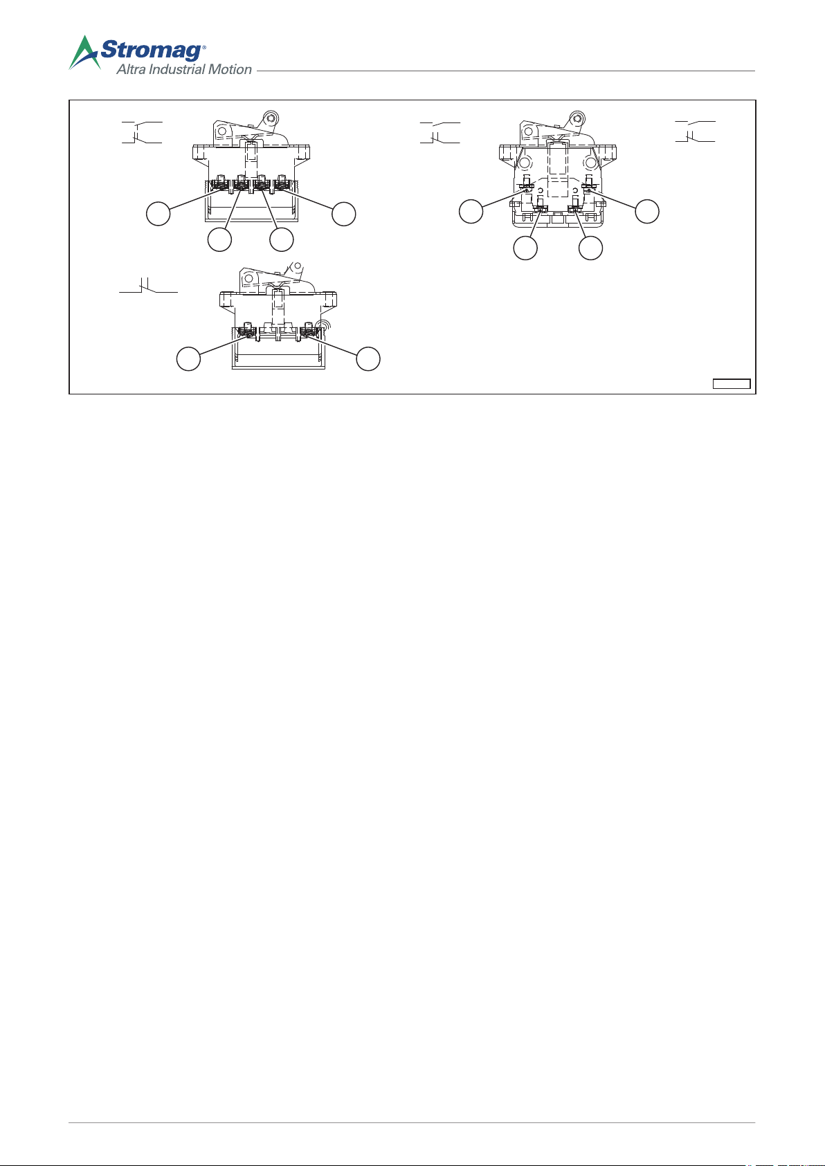
EKM-0114
51
2
4
1
3
13
21
14
22
52
22
14
21
13
53
54
4
3
4
3
21
1413
21 22
3 4
D) E)
G)
F)
Fig. 2
D 51: Circuit changeover with twin break
electrically isolated contact bridges
E 52: Circuit changeover quick action with
twin break contact bridges electrically isolated from each other
F 53: Circuit changeover button with twin
break contact bridges electrically isolated
from each other
1, 2, 3, 4,
13, 14,
21, 22
G 54: Circuit breaker switch
Connection points
14
Mounting/operating instructions Gear limit switch Type series HGE • No. 152-00000 F • 10/2017
Page 19

Alternating current AC
Contact Con-
tact
material
Designation
Circuit as a changeover
Circuit as an NC contact
513)● ● ● ●
523)● ● ● ● ●
533)● ● ● ● ● 1x10
54 ● ● ● ● ● 6A 30x10
80 ● ● ● ● ● 3A
81 ● ● ● ● ● 3A
90 ● ● ● ● ● 1A
90
● ● ● ● ● 0.25A 230V
G
88 ● ● ● ● ● 1.5A 230V
1)
Values for resistive load
2)
EN 60947–5–1
3)
Gold contacts for switching power < 24V – 100mA
Switc
hing
Con-
nection
system
Silver
Gold (SPS application)
Switch
Quick break switch
Func
Electrical data Operat-
tion
2)
continuous thermal current
th
6A
10A
10A 400V
1)
I
Screw connection; 0,75 - 2,5 mn² AWG 20 ... 14
Forced opening
Connecting cable switching power according to EN 60947-5-1
AC-15
2.5A
230V
Connecting cable switching power according to EN 60947-5-1
AC-12
1)
1)
ing life
rated insulation voltage
i
U
30x10
250V
10x10
1,5x10
Temperature
Mechanical Operating life
6
6
6
6
6
Service temperature
-30°C …
+85°C
-25°C …
+80°C
-30°C …
+85°C
-40°C …
+85°C
-55°C …
+85°C
Mounting/operating instructions Gear limit switch Type series HGE • No. 152-00000 F • 10/2017
15
Page 20

Direct current DC
Contact Con-
tactmaterial
Designation
Circuit as a changeover
Circuit as an NC contact
513)● ● ● ● 4A
523)● ● ● ● ● 6A
533)● ● ● ● ● 6A 1x10
54 ● ● ● ● ● 1A 6A 30x10
80 ● ● ● ● ● 1A
81 ● ● ● ● ● 1A
90 ● ● ● ● ● 0.5A
90G ● ● ● ● ● 0.5A 0.25A 110V
88 ● ● ● ● ● 1.5A 24V
1)
Values for resistive load
2)
EN 60947–5–1
3)
Gold contacts for switching power < 24V – 100mA
Switc
hing
Con-
nection
system
Silver
Gold (SPS application)
Quick break switch
Switch
Func
Electrical data Operat-
tion
2)
Connecting cable switching power
Screw connection;
0,75 - 2,5 mn² AWG 20 … 14
Forced opening
according to EN 60947-5-1
24V
110V
DC-13
1)
1)
1)
ing life
continuous thermal current
6A
10A
10A 400V
1)
I
Connecting cable switching power
according to EN 60947-5-1
DC-12
rated insulation voltage
250V
U
i
30x10
10x10
1,5x10
th
Temperature
Mechanical Operating life
6
6
6
6
6
Service temperature
-30°C …
+85°C
-25°C …
+80°C
-30°C …
+85°C
-40°C …
+85°C
-55°C …
+85°C
4.1.5 Contact positions
The required dimensions and weights in kg can be obtained from the respective GTES dimensional drawing.
This can be requested as a separate document from Stromag’s Customer Care department.
16
Mounting/operating instructions Gear limit switch Type series HGE • No. 152-00000 F • 10/2017
Page 21

4.1.6 Type code
155_HGE_590_BFV_50_A1R
EKM-0128
Example: 155 HGE 5 90 B F V 50 A1R
155 Nominal revolutions, see section 4.1.2.
Fig. 3
HGE Switch type
5 Number of fitted contacts
90 Type of fitted contacts, see section 4.1.4.
B Block adjustment (only for cam discs Ø 70 mm)
D Doubled (fine adjustment)
F Fine adjustment
V Adjustability of the switching points
Diameter of the installed cam disc 50 not for block adjustment
50
Switch size A1R Contact space 1 to 5, right
A1R
70 not for contact 52, 53
(standard)
A2R Contact space 2 to 8, right
(standard)
A1L Contact space 1 to 5, left
A2L Contact space 2 to 8, left
B11 Contact space 5 to 11, both
sides
B22 Contact space 8 to 22, both
sides
B12 Contact space 1 to 5, left /
B21 Contact space 2 to 8, left /
Mounting/operating instructions Gear limit switch Type series HGE • No. 152-00000 F • 10/2017
contact space 2 to 8, right
contact space 1 to 5, right
17
Page 22

All switches with CE marking, other approvals are possible, see marking on the type plate or in the attached
document:
CSA Canada GOST-R Russia
CCC China TAT Approval on request
4.2 Dimensional drawing
NOTE
Stromag would like to emphasise that users should refer to the dimensional drawing for all technical
details, including: dimensions, weights, tolerances, tightening torques, and any other technical specifications and units required for assembly, such as securing equipment and lubricants.
Should this information be necessary during assembly, a reference will be made in the dimensional
drawing at the respective point in this documentation.
A dimensional drawing is supplied as a separate document and can be requested additionally from
Stromag Customer Care. For this, the same product data is required as when ordering spare parts.
4.3
Marking on the product
The following data can be found on the housing of the GTES:
Manufacturer's address, order number, designation, month/year of construction, marking, voltage Ui, current I
NOTE
Switches and housings have identical type plates. The data, for e.g. for a spare part order, must be
read from the respective assembly group.
th.
18
Mounting/operating instructions Gear limit switch Type series HGE • No. 152-00000 F • 10/2017
Page 23

5 Construction and function
EKM-0127
A1R A1L
B11
5.1 Switch sizes
A1R
A1L
Switch size A1R
Switch size A1L
Fig. 4
B11 Switch size A1R
The switch sizes shown in the figure above present a selection. The overview of all switch sizes can be obtained
from the type code explanation, see section 4.1.6.
Mounting/operating instructions Gear limit switch Type series HGE • No. 152-00000 F • 10/2017
19
Page 24

5.2 Component designations
EKM-0120
11
22
33
44
55
66
Housing with gear part
1
Contacts
2
Cam disc
3
Fig. 5
4 Flange
5 Drive shaft, design with parallel key
7 Cam disc group
The component designations of the GTES are given here as an example with switch size A1R.
5.3 Design, task and function of the assembly groups
The limit switch consists of a gear part and one or two switch parts (design A or design B), which are firmly fitted
to each other.
The speed of the last gear part will be transferred via positive locking on the switching shaft. The cam discs
fastened to the switching shaft for operation of the contacts can be adjusted infinitely and independently from
each other. As additional equipment, a block adjustment can be fitted, whereby the cam discs that can be individually adjusted to each other can be adjusted as a block.
According to the required contact arrangement, cam discs with 40° or 180°can be fitted − cams are fitted in series and all other degree values are fitted as special equipment. The switch settings of the cam discs can be
adjusted by the customer, see section 6.6.
The gearbox is a combination of worm and spur gears. For the gearbox with 35 nominal revolutions, a worm
gear reduction is installed. The drive shaft is installed transversely to the switching shaft and can be equipped
with an encoder as a special shaft with a second shaft end for 1:1 drive. The gear wheels installed are a brasssteel combination. The lubrication applied during assembly is sufficient for lifetime lubrication.
For the shaft bearing, maintenance-free grooved ball bearings are fitted. A check of the lubrication is not necessary.
The housing is made of salt water resistant aluminium. The cover is sealed to the gearbox housing with O-rings.
The switch housing complies with protection class IP 65 in accordance with EN 60529.
20
Mounting/operating instructions Gear limit switch Type series HGE • No. 152-00000 F • 10/2017
Page 25

5.3.1 Electrical connections
All contact connectors can be found within the switch housing. The earth conductor for grounding the housing
can be found on the bearing plate. The electrical connections for contact connectors and earth conductors occur
via screw connections. The bores for cable entry points are closed with blind plugs for delivery of the switch.
The bores can be found in the gearbox housing. Depending on the cable type used, the corresponding blind
plugs are replaced through cable entry points by the customer. The cable ends reach the contacts via the cable
entry point on the connecting terminals. Each contact is provided with protection against accidental contact.
NOTE
For contact 51, the following applies:
The protection against accidental contact must be removed for wiring.
DANGER
Risk of accidents caused by live components
There are live components in the area of the electrical connections.
► After wiring, each contact must be provided with protection against accidental contact according to
the Low Voltage Directive 73/23 EWG.
► Connect the marked earth conductor to the bearing plate with the earth conductor.
• Cable entry points: see dimension sheet.
• Contact connector wiring:
• for every 2 solid-core or 2 multi-stranded copper wires with wire end sleeves,
• Wire cross-section: 0.75 mm2 to 2,5 mm2, AWG 20 ... 14,
• Tightening torques, see section 6.2.3.
5.3.2 Mounting position
The mounting position of the GTES is optional.
Mounting/operating instructions Gear limit switch Type series HGE • No. 152-00000 F • 10/2017
21
Page 26

5.3.3 Drive flange
4
10
14
3.04
11.8
+0.1
5 1
20
H7
ø54
23.5
10
M6
EKM-0092
3 Nm (+/- 0,5 Nm)
a
b
c
BA
- 0.01
ø8
- 0.05
11.4
+ 0.1
4.04
- 0.01
ø30
- 0.1
3xM6 ø42
±0.2
_
^
22
_
^
As far as is possible, the drive should occur free of shear force through the drive flange type F or type F+M that
is suitable for the switch, see section 6.2.4.
Fig. 6
A Flexible drive flange type F B
a 3 x carrier 120° diameter: 42 ± 0,2 b Carrier bore diameter: 8,5
c M4 8 deep
Torsion angle at 5 Nm: 5 ± 0.5°
5.4 Optional equipment available
5.4.1 Design with additional potentiometer
A potentiometer (7) is installed in the HGE in a separate installation space opposite the contact space in switch
design "B". The drive is actuated by the switching shaft.
The following designs are available:
• Potentiometer with a maximum diameter of 60 mm: Torsionally-stiff coupling design, see section 5.4.2.
• Potentiometer with a diameter larger than 60 mm either for transmission or reduction of the switching shaft:
Design with gear wheels, see section 5.4.3.
Flexible drive flange type F+M
22
Mounting/operating instructions Gear limit switch Type series HGE • No. 152-00000 F • 10/2017
Page 27

5.4.2 Adjustment of the potentiometer with drive via a torsionally-stiff coupling
EKM-0093
4
7
5
EKM-0094
1
237
4 Clamping nut 7 Potentiometer
5 Servo clamps
Fig. 7
According to the design, the potentiometer (7) is fastened to a support plate (3) with a clamping nut (4) or with
servo clamps (5).
Adjusting the potentiometer
1. Loosen the clamping nut (4) or servo clamps (5).
2. Turn the resistance housing.
3. Fasten the clamping nut (4) or servo clamps (5).
5.4.3 Adjustment of the potentiometer when the drive is over gear wheels
1 Clamp bolt (in the gear wheel) 7 Potentiometer
2 Gear wheel
Mounting/operating instructions Gear limit switch Type series HGE • No. 152-00000 F • 10/2017
Fig. 8
23
Page 28

Proceed as follows when using a drive over gear wheels for adjustment of the potentiometer:
EKM-0095
b
a
*
U
B
PTC
1 2
Adjusting the potentiometer
1. Loosen the clamp bolt (1).
2. With the switching shaft stationary: Turn the gear wheel.
3. Screw the clamp bolt (1) in tightly.
5.4.4 Design with heating resistor
The GTES can optionally be provided with heating.
Fig. 9
a Gearbox side b Equivalent circuit diagram
* Connection voltage according to the version
used: 12 – 36V AC/DC or 110 – 250V AC/DC
The heating serves to prevent water condensation in the switch room. This heating is designed so that according to the voltage, a heat output of approx. 2,5 Watts or 4 Watts is available. Depending on the order, the corresponding supply voltage amounts to 12 − 36V AC/DC or 110 − 250V AC/DC. The PTC heating is self-regulating
and temperature-limiting, and thus leads to an automatic adjustment to the ambient temperature.
ATTENTION
Risk of accidents due to hot surfaces
Contact with the surface of the heating may lead to severe burns.
► Wear personal protective equipment.
► Wait until the surface has cooled.
Design: U
Heat output (in lined out condition) approx. 2,5 Watts approx. 4 Watts
PTC cooling resistor (at 25 °C) R2520 Ω ± 35 % R251500 Ω ± 35 %
PTC reference temperature 50 °C 50 °C
Protection class (VDE 0100, 0160) II II
Connecting cable 2 x 0,25 mm2, silicone cable 2 x 0,25 mm2, silicone cable
Radiator Anodised aluminium Anodised aluminium
Weight approx. 40 g approx. 40 g
B
12 − 36 V AC/DC 110 − 250 V AC/DC
24
Mounting/operating instructions Gear limit switch Type series HGE • No. 152-00000 F • 10/2017
Page 29

6 Assembly
6.1 Special safety guidelines
CAUTION
Risk of accidents caused by live components
For all work on components or individual parts, the machine must be switched off and secured
against non-intended reconnection.
► Check that the machine is de-energised before beginning the work.
CAUTION
Risk of accidents caused by rotating components
Risk of entanglement in the area between the GTES and the machine due to rotating components.
► The operator must install a covering above the connecting flange.
NOTICE
Damage to the machine due to the incorrect adjustment of the GTES
When the GTES has not been adjusted, traverse movements of the machine can lead to damage.
► Before commissioning the machine, always adjust the GTES first in accordance with the specifica-
tions in the mounting/operating instructions.
The installation regulations applicable on-site and the mounting instructions of the machine manufacturer must
be observed.
6.2 Conditions for assembly and fixing
Required assembly space:
• basic cover height
Assembly sequence:
• Mechanical assembly, see section 6.3.
• Electrical connection, see section 6.4.
• Switching point adjustment, see section 6.6.
• Completion of the housing, see section 6.7.
6.2.1 Special tools
A special tool is not necessary for standard designs.
6.2.2 Assembly precision
Avoid misalignments and offsets between the drive shaft of the GTES and the machine.
Mounting/operating instructions Gear limit switch Type series HGE • No. 152-00000 F • 10/2017
25
Page 30

6.2.3 Tightening torques
EKM-0124
11
32
Unless otherwise specified, the screws should be tightened according to the tightening torques provided in the
DIN.
Machine and adjacent construction fixing elements must be tightened according to the manufacturer's instructions.
Location/connection Tightening torque [Nm] Comment
Flange on the machine housing See section 6.3 et seq. See operating instructions of the complete machine
Housing (feet) on the machine See section 6.3 et seq. See operating instructions of the complete machine
Earth conductor 2,5 Nm See section 6.4.4
Screw connection on the contact 1 Nm See section 6.4.2
Cover 2,5 Nm See section 6.7
6.2.4 Requirements for the connecting components
The GTES can only be fitted on machines that have a CE marking.
6.3 Assembly mechanics
Before assembly of the GTES, the machine must be suitably positioned so that the installation space is easily
accessible.
NOTE
When driving screws into the machine-side threads, the following can be obtained from the operating
instructions of the machine:
► Screw tightening torques,
► screw locking agent to be used, if necessary.
NOTE
The installation space must be and remain dust-free and dry.
6.3.1 Assembly of the housing (design without flange)
Mount the GTES
on the machine
1. Create a positive-locking connection between the
drive shaft (1) of the GTES and the machine.
Fig. 10
26
Mounting/operating instructions Gear limit switch Type series HGE • No. 152-00000 F • 10/2017
Page 31
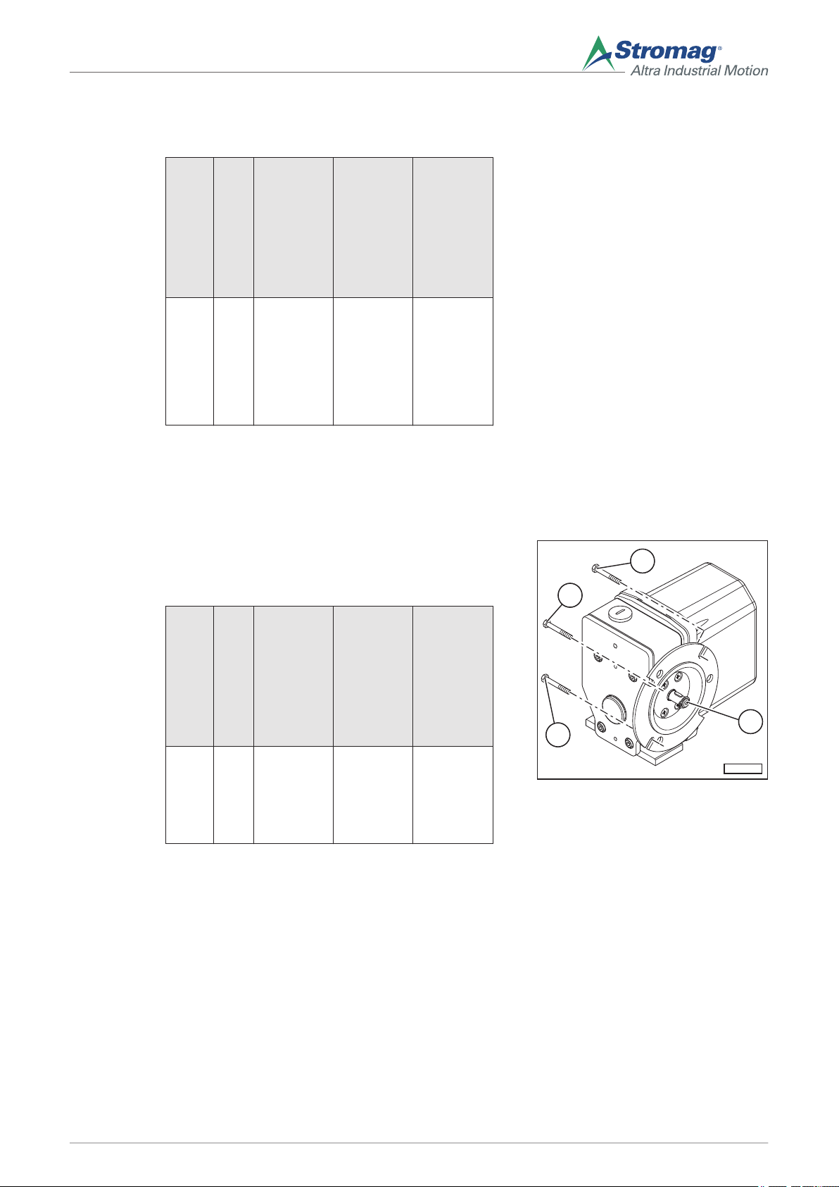
2. Depending on the installation conditions: Mount the
EKM-0125
12
12
12
11
GTES on the housing using screws, see the following table.
Item no.
(2) 2 Housing
Number of screws
Position
side
Screws
M8 Unless oth-
3. Adjust the switching points, see section 6.6.
4. Mount the cover, see section 6.7.
6.3.2 Assembly of the housing (design with flange)
Mount the GTES
on the machine
1. The connection between the drive shaft of the GTES
and the machine must be positively locked.
2. Mount the flange (1) with screws (2).
Tightening torque
erwise
specified in
the operating instructions of the
machine:
10 Nm
Item no.
(2) min.3Input side M6, offset
Number of screws
Position
Screws
by 120°
(evenly distributed on
the circumference)
Tightening torque
See operating instructions of the
machine
Fig. 11
3. For adjusting switching points, see section 6.6.
4. Mount the housing cover, see section 6.7.
6.4 Electrical assembly
After electrical assembly or maintenance, the safety measures applied must be tested (e.g. ground resistance).
The connection of the wire outlets must be carried out by an electrician according to the Electrical Code of
Practice.
The safety guidelines attached to the GTES must be observed.
Mounting/operating instructions Gear limit switch Type series HGE • No. 152-00000 F • 10/2017
27
Page 32

6.4.1 Insert the connection cable into the GTES
EKM-0015
EKM-0108
1
3
2
EKM-0109
1
Insertion of the
connection cable
1. Insert the machine-side connection cable via the cable entry point (1) in the switch housing.
NOTE
The cable screws used must correspond to
at least the protection class of the housing
used, see section 2.14.3.
Preferably metal screws should be used.
When mounting the cable, it is especially important to ensure that after insertion, the union nut (2) is thoroughly tightened (depending
on the cable manufacturer, 2 - 3 Nm).
As the plastic sheath remains deformed at
the clamping point in the cable gland with
some cables, retighten the clamping nut as
necessary after 2 weeks.
The cable entry point for the GTES should be
carried out in such a way that no water can
be conducted by the cable to the cable gland.
6.4.2 Connect the contacts
Connection of
the contacts
1. Loosen the screw connection of the cover and remove the cover.
Fig. 12
2. This applies exclusively to contacts 51 and 54: Remove the protection against accidental contact (1).
3. Strip the ends (3) of the connecting cables by 6 mm.
4. Plug the cable in and tighten the screw connection
using a screwdriver (2), see section 6.2.3.
5. If no further connections are to be made: put the
protection against accidental contact in place, close
and screw in the cover directly. Tightening torques,
see section 6.2.3.
6.4.3 Connect the heating
Connection of
the heating
Contact with the surface of the heating may lead to severe burns.
► Wear personal protective equipment.
► Wait until the surface has cooled.
Fig. 13
ATTENTION
Risk of accidents due to hot surfaces
1. Loosen the screw connection of the cover and remove the cover.
Fig. 14
28
Mounting/operating instructions Gear limit switch Type series HGE • No. 152-00000 F • 10/2017
Page 33
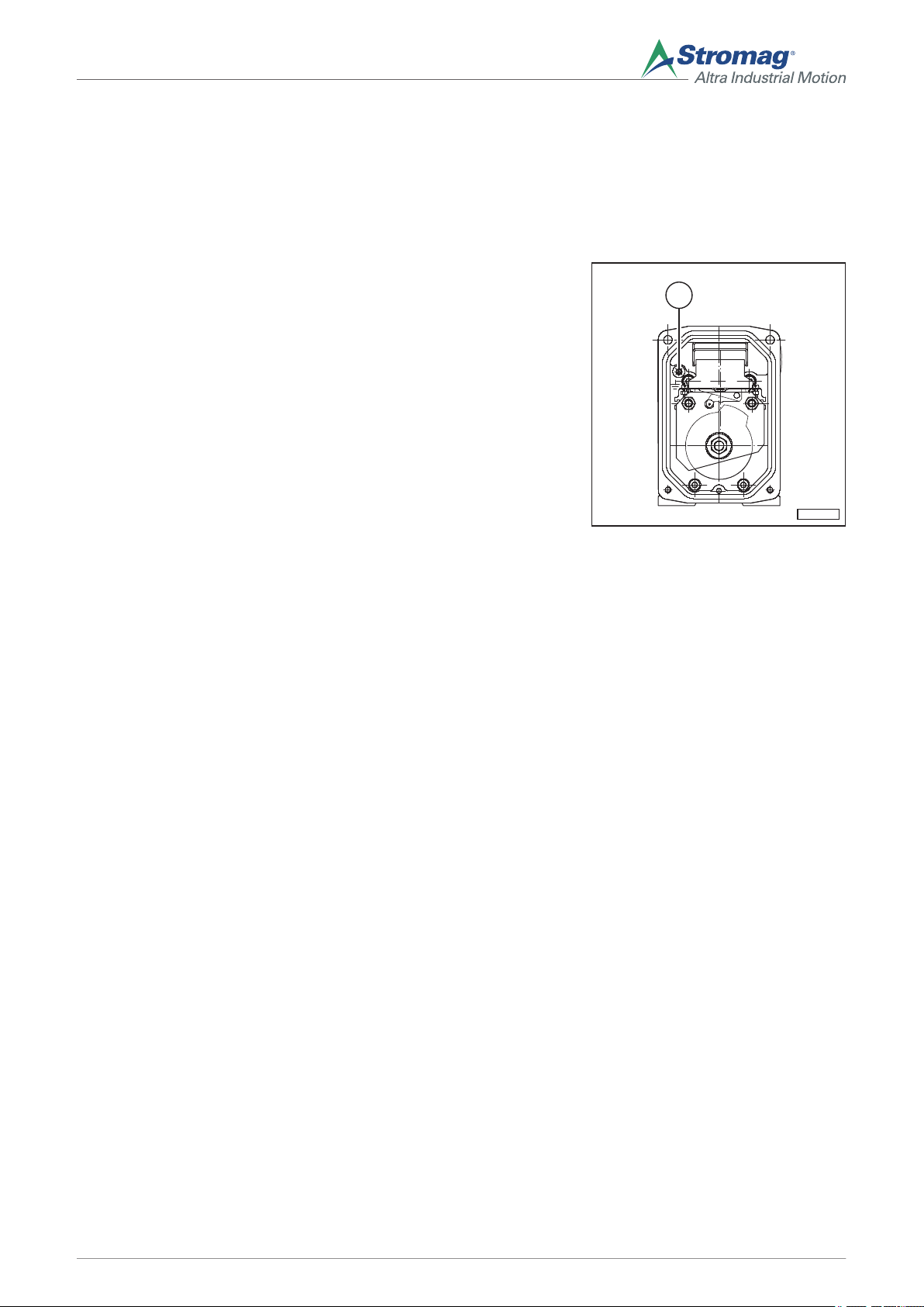
2. Connect the heating via a 2-pole terminal block.
EKM-0112
1
3. If no further connections are to be made: close and
screw in the cover directly. Tightening torques, see
section 6.2.3.
6.4.4 Connect the earth conductor
Earth conductor
connection
An earth conductor of up to 1,5 mm2 (min. wire crosssection of the connecting cable) can be connected.
1. Strip the ends of the earth conductors by approx.
6 mm.
2. Plug the cable in and tighten the screw [2,5 Nm].
6.5 Connection diagrams
6.5.1 Electrics
The contacts can be freely assigned.
6.6 Switching point adjustment
Fig. 15
Adjustment procedure:
• Remove the cover of the GTES.
• Carry out the adjustment.
• Remount the cover of the GTES immediately.
After the switching point adjustment, immediately seal the GTES with the cover so that no dust or water can
enter and affect the safety off switch.
The switching point adjustment is determined by the design of the contact used, see section 4.1.6. There is
• Normal adjustment “V50”
• Fine adjustment “FV 50”
• Double fine adjustment “DFV”
• Normal adjustment “V70”
• Fine adjustment “FV70”
• Block adjustment “BV”
• Block adjustment “BFV”
Mounting/operating instructions Gear limit switch Type series HGE • No. 152-00000 F • 10/2017
29
Page 34

NOTE
The cam discs are designed so that a constant nominal travel and castor run are available. No damage is caused when the castor run is exceeded. The contact readopts the previous switching position.
Preparations
CAUTION
Risk of accidents caused by live components
There are live components in the area of the electrical connections.
► Ensure that the live connections in the GTES are covered with a protection
against accidental contact and that no contact with the connections is possible.
To prepare the switching point adjustment, carry out the following steps:
1. Carefully move the machine manually into the designated switch-off position of the GTES.
2. Switch the machine off and secure it against unintentional commissioning.
3. Loosen the cover screws, and disassemble the GTES cover.
CAUTION
Risk of accidents caused by live components
When in open condition, the inner area of the GTES must be protected from dust
and water.
► Ensure before opening the GTES that no dust or water can get into the housing.
CAUTION
Risk of accidents due to rotating parts
To adjust the switching point, the machine must be switched on, proceed as described below:
► Leave the movement area of the machine.
► Start the switching point at a safe distance from the machine.
► Switch the machine off and secure it from switching back on.
► Carry out the adjustment of the switching point that was started.
4. Proceed with the respective contact selection, see the following chapter.
30
Mounting/operating instructions Gear limit switch Type series HGE • No. 152-00000 F • 10/2017
Page 35

6.6.1 Normal adjustment "V50"
EKM-0096
5
6
1
3
4
2
Fig. 16
Two cam discs are arranged for each contact, which are continuously adjustable. According to the position of
the cam, the castor run can be doubled for a contact and the nominal travel shortened accordingly. The effective
cam angle (5) and the usable angle of the cam disc (6) are illustrated in the figure.
1. Loosen the nut (3).
Turn the cam discs (1) by hand to the required switching positions. To do so, use the 30° graduation of the
cam disc in conjunction with the pointer tip (4) of the locking plate (2) as an aid.
NOTE
The cam discs (1) can be adjusted independently of one another after loosening the nut (3). The locking plate (2) prevents the adjustment of a previously adjusted cam disc by adjusting the next disc.
2. Tighten the nut (3) to a tightening torque of 2,5 Nm.
3. All adjustments must be looked at in an inspection round and checked for functionality.
4. Mount the cover of the GTES, see section 6.7.
Mounting/operating instructions Gear limit switch Type series HGE • No. 152-00000 F • 10/2017
31
Page 36

6.6.2 Fine adjustment “FV50”
EKM-0097
xy
76
x*
y*
10
11
28
3
Fig. 17
Each contact is assigned to a cam disc group, consisting of an adjustable cam (6) and cam disc (7). The adjustable cam (6) is connected via positive locking over a ring with toothing on both sides (2) to the switching shaft.
While the worm’s (8) self-locking feature is enabled, the torque is transferred further by means of positive locking from the adjustable cam (6) to the toothing of the cam disc (7). The cam disc (7) can be adjusted by rotating
the worm (8) at a ratio of 74:1 (1 revolution of the worm = 4,865° on the cam disc) towards the periphery. The
effective cam angle (10) and the usable angle of the cam disc (11) are shown in the figure. x* and y* depict the
views.
1. Loosen the nut (3) until the front toothing disengages for one adjustable cam. The adjustment can then take
place without the other cam disc groups also being adjusted.
Turn the selected cam discs (1) by hand to the required, approximate switching positions.
2. Tighten the nut (3) to a tightening torque of 2,5 Nm.
3. Using a screw driver, max. width of 4 mm, turn the screw on the adjustment worm (8) until the switching point
has been adjusted as desired. An extremely fine adjustment is possible from both sides, without having to
loosen the nut (3).
4. All adjustments must be looked at in an inspection round and checked for functionality.
5. Mount the cover of the GTES, see section 6.7.
32
Mounting/operating instructions Gear limit switch Type series HGE • No. 152-00000 F • 10/2017
Page 37

6.6.3 Double fine adjustment "DFV"
xy
x*
y*
EKM-0098
10
11
7628
3
7a
7b
Fig. 18
Two cam disc groups are assigned to each contact, consisting of adjustable cams (6) and cam discs (7). Each
cam disc pair can be adjusted infinitely and used in a defined way from both sides. The effective cam angle (10)
and the usable angle of the cam disc (11) are shown in the figure. x* and y* depict the views.
1. Loosen the nut (3) until the front toothing disengages for one adjustable cam. The adjustment can then take
place without the other cam disc groups also being adjusted.
Turn the selected cam disc (7) by hand to the required, approximate switching positions and to the required
cam angle.
2. Tighten the nut (3) to a tightening torque of 2,5 Nm.
3. Using a screw driver, max. width of 4 mm, turn the screw on the adjustment worm (8) until the switching point
has been adjusted as desired and the required cam angle has been achieved. An extremely fine adjustment
is possible from both sides, without having to loosen the nut (3).
4. All adjustments must be looked at in an inspection round and checked for functionality.
5. Mount the cover of the GTES, see section 6.7.
Mounting/operating instructions Gear limit switch Type series HGE • No. 152-00000 F • 10/2017
33
Page 38
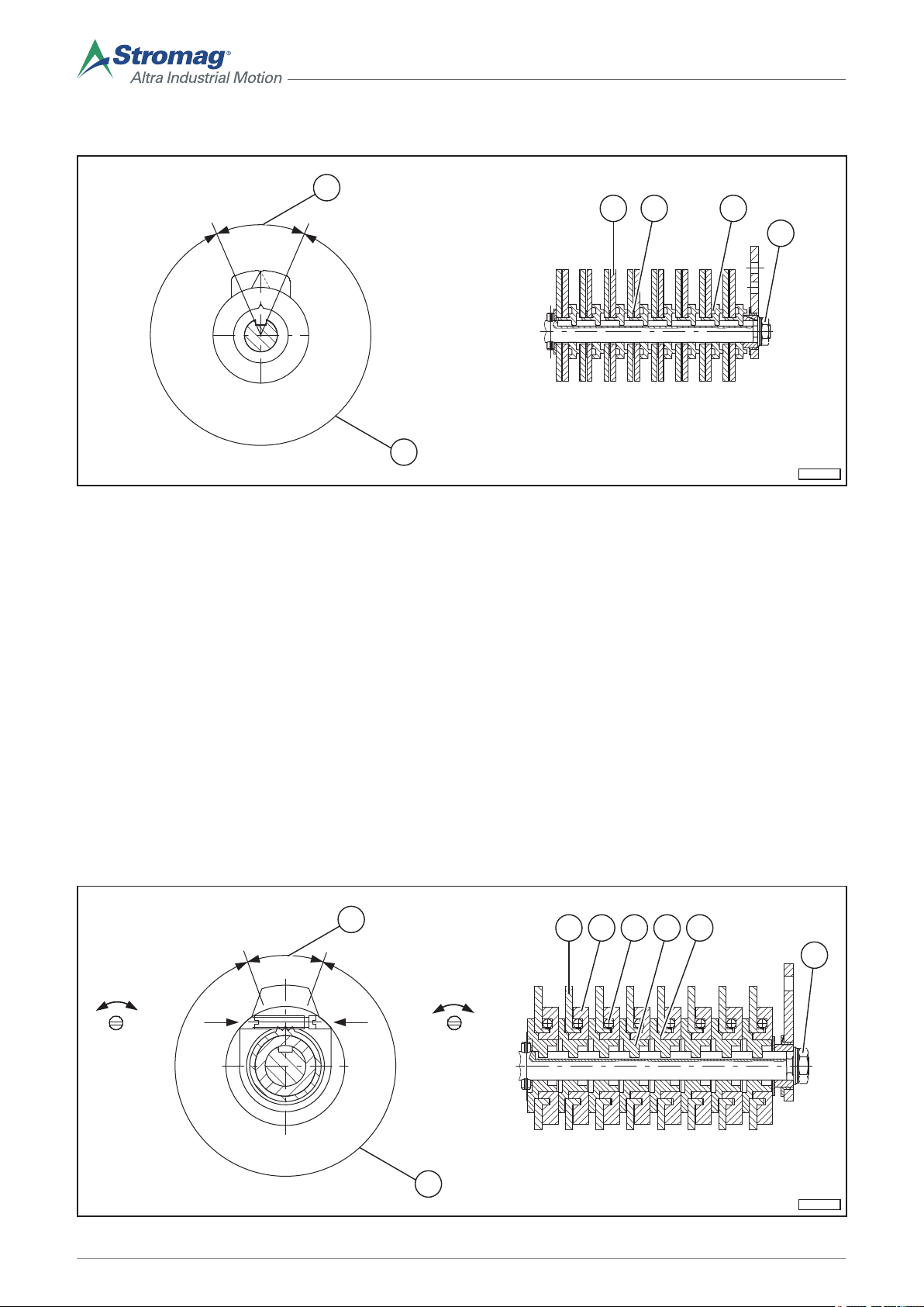
6.6.4 Normal adjustment "V70"
EKM-0099
10
11
421
3
EKM-0100
x*
y*
xy
4 6321
5
10
11
Fig. 19
Two cam discs are arranged for each contact, which are continuously adjustable. The cam discs (1) can be
adjusted independently of one another after loosening the nut (3). The locking plate (2) as well as the inner ring
(4) thereby prevent the adjustment of a previously adjusted cam disc by adjusting the next disc.
According to the position of the cam, the castor run can be doubled for a contact and the nominal travel shortened accordingly.
The effective cam angle (10) and the usable angle of the cam disc (11) are shown in the figure.
1. Loosen the nut (3) until the front toothing disengages for one adjustable cam. The adjustment can then take
place without the other cam disc groups also being adjusted.
Turn the selected cam discs (1) by hand to the required switching positions and cam angle.
2. Tighten the nut (3) to a tightening torque of 2,5 Nm.
3. All adjustments must be looked at in an inspection round and checked for functionality.
4. Mount the cover of the GTES, see section 6.7.
6.6.5 Fine adjustment “FV70”
34
Mounting/operating instructions Gear limit switch Type series HGE • No. 152-00000 F • 10/2017
Fig. 20
Page 39

A cam disc group is assigned to each contact, consisting of a cam disc (1), adjustable cam (2), adjustment
EKM-0102
3
4 621
10
11
worm (3) and tooth ring (4). The adjustable cam (2) is connected to the switching shaft by means of positive
locking via a tooth ring (4). The adjustment worm (3) with a self-locking feature transfers the torque further by
means of positive locking from the adjustable cam (2) to the toothing of the cam disc (1). The cam disc (1) can
be adjusted by rotating the adjustment worm (3) at a ratio of 108:1 (1 revolution of the worm = 3.333° on the
cam disc) towards the periphery. The effective cam angle (10) and the usable angle of the cam disc (11) are
shown in the figure. x* and y* depict the views.
1. Loosen the nut (5) until the front toothing (6) for one adjustable cam is disengaged. The adjustment can then
take place without the other cam disc groups also being adjusted.
2. Turn the selected cam discs (1) by hand to the required, approximate switching positions.
3. Tighten the nut (5) to a tightening torque of 2,5 Nm.
4. Using a screw driver, max. width of 4 mm, turn the screw on the adjustment worm (8) until the switching point
has been adjusted as desired. An extremely fine adjustment is possible from both sides, without having to
loosen the nut (5).
5. All adjustments must be looked at in an inspection round and checked for functionality.
6. Mount the cover of the GTES, see section 6.7.
6.6.6 Block adjustment "BV"
Fig. 21
Two cam discs (1) are assigned to each contact. They can be adjusted infinitely and are clamped to a common
block adjustment sleeve (4) using a lock nut (6). The cam discs (1) can be adjusted independently of one
another after loosening the capstan nut (6) using a pin with a diameter of 3,5 mm. The locking plate (2) thereby
prevents the adjustment of a previously adjusted cam disc by adjusting the next disc. According to the position
of the cam, the castor run can be doubled for a contact and the nominal travel shortened accordingly. The
effective cam angle (10) and the usable angle of the cam disc (11) are shown in the figure.
Adjusting individual cam discs
Mounting/operating instructions Gear limit switch Type series HGE • No. 152-00000 F • 10/2017
To adjust the switching points, proceed as follows:
1. Loosen the capstan nut (6).
Turn the selected cam discs (1) to the required switching positions and cam angle.
2. Tighten the capstan nut (5) to a tightening torque of 2,5 Nm.
3. All adjustments must be looked at in an inspection round and checked for functionality.
4. Mount the cover of the GTES, see section 6.7.
35
Page 40

Adjusting the
EKM-0101
x*
y*
xy
21 56 83 7
4
10
11
NOTE
complete cam
block
A block adjustment is offered when the adjusted individual switching points should
not be altered to each other, for example, when the wire length is changed. With a
block adjustment, the relative adjustment of the individual contacts to each other
remains unchanged.
1. Loosen the nut (3).
2. Turn the complete switching block by hand to the required switching position.
3. Tighten the nut (3) to a tightening torque of 2,5 Nm.
4. All adjustments must be looked at in an inspection round and checked for functionality.
5. Mount the cover of the GTES, see section 6.7.
6.6.7 Block adjustment "BFV"
A cam disc group is assigned to each contact, consisting of a cam disc (1), adjustable cam (2), adjustment
worm (3) and toothed spacer (4). The adjustable cam (2) is connected via positive locking to the block
adjustment sleeve (6) over the spacer (4). The adjustment worm (3) with a self-locking feature transfers the
torque further by means of positive locking from the adjustable cam (2) to the toothing of the cam disc (1). The
cam disc (1) can be adjusted by rotation of the adjustment worm (3) at a ratio of 108:1 (1 revolution of the
adjustment worm = 3,333° on the cam disc) in peripheral direction. The effective cam angle (10) and the usable
angle of the cam disc (11) are shown in the figure. x* and y* depict the views.
Adjusting individual cam discs
To adjust the switching points, proceed as follows:
1. Loosen the capstan nut (7).
2. Tighten the capstan nut (7) to a tightening torque of 2,5 Nm.
3. Using a screw driver, max. width of 4 mm, turn the screw on the adjustment worm (3) until
Turn the selected cam discs (1) to the required, approximate switching positions.
the switching point has been adjusted as desired. An extremely fine adjustment is possible
from both sides, without having to loosen the nut (5).
4. All adjustments must be looked at in an inspection round and checked for functionality.
5. Mount the cover of the GTES, see section 6.7.
Fig. 22
36
Mounting/operating instructions Gear limit switch Type series HGE • No. 152-00000 F • 10/2017
Page 41

Adjusting the
EKM-0126
33
22
11
complete cam
block
1. Loosen the nut (5).
2. Turn the complete switching block by hand to the required switching position.
3. Tighten the nut (5) to a tightening torque of 2,5 Nm.
4. Mount the cover of the GTES, see section 6.7.
6.7 Mount the cover
NOTE
The screws must be fully screwed in.
NOTE
A block adjustment is offered when the adjusted individual switching points should
not be altered to each other, for example, when the wire length is changed. With a
block adjustment, the relative adjustment of the individual contacts to each other
remains unchanged.
Assembly of the
cover
When fitting the cover, ensure that the screws are fully
and uniformly tightened in order to avoid tilting the cover and poor contact pressure of the seal.
1. Check the seal (3) on the cover (2) for cracks or
damage.
NOTE
Replace damaged seals.
2. Fit the cover with the seal.
NOTE
The screws must be fully screwed in.
3. Fix the cover with 4 screws (1) and washers, see
section 6.2.3.
6.8 Correct disposal/recycling of operating and auxiliary materials.
Materials that can be recycled must be included in the waste disposal cycle.
Local regulations in the country of operation determine the disposal of components.
Fig. 23
7 Operation
7.1 Special safety guidelines.
See operating instructions of the machine.
7.2 Initial commissioning
The adjustment of the GTES is only permitted when the machine is at a standstill.
7.3 Use
Use of the GTES is not necessary, see the operating instructions of the machine.
Mounting/operating instructions Gear limit switch Type series HGE • No. 152-00000 F • 10/2017
37
Page 42

7.3.1 Operating conditions
See section 4.1.
7.4 Recommissioning
No specific measures are necessary for recommissioning.
7.5 Decommissioning
7.5.1 Temporary decommissioning
No specific measures are necessary for temporary decommissioning.
7.5.2 Final decommissioning
No specific measures are necessary for final decommissioning.
Dispose of materials according to local regulations.
8 Maintenance and inspections
8.1 Special safety guidelines
CAUTION
Risk of accidents due to non-observance of the safety guidelines
There is a risk of accidents if the general safety guidelines are not observed.
► All safety guidelines must be observed, see section 2.
8.2 Measures for environmental protection
RECYCLING
Dispose of components as well as auxiliary and operating materials according to the local guidelines
in a correct and environmentally-friendly way.
8.3
General points
The GTES switching points are checked as part of a performance check of the machine.
NOTE
When using the GTES in hoists, proceed according to the applicable guidelines and standards for the
entire machine.
8.4 Maintenance and inspection intervals
In principle, no maintenance work or inspections are necessary for the GTES.
38
Mounting/operating instructions Gear limit switch Type series HGE • No. 152-00000 F • 10/2017
Page 43

8.4.1 Cleaning
Dust deposits on the housing of the GTES are irrelevant in terms of the function. The dust can be removed during maintenance of the machine with a dry cloth.
NOTICE
Damage to the GTES caused by cleaning agents/solvents
Contact with cleaning agents or solvents may lead to damage.
► Any contact with cleaning agents or solvents must be avoided.
NOTICE
Damage to the GTES due to contamination
Dust deposits on the GTES must not be removed with compressed air.
By cleaning with compressed air, dust can enter the contact and the gear, and affect the switching
capacity.
► Never hold a compressed air jet in an open housing.
► Only use dry cloths for cleaning.
NOTE
The seals of the cover must be replaced as necessary after repeated opening of the cover.
9 Troubleshooting
9.1 Operational issues and their solutions
No typical GTES malfunctions are known, should you have any queries regarding adjustment or commissioning,
please contact Stromag’s Customer Care department, see section 11.2.
10 Disassembly
10.1 Special safety guidelines
CAUTION
Risk of accidents due to non-observance of the safety guidelines
There is a risk of accidents if the general safety guidelines are not observed.
► All safety guidelines must be observed, see section 2.
10.2 Removing the GTES
Disassembly of the GTES is carried out in the opposite way to assembly.
• Switch the machine off and secure it from switching back on.
• Remove the cover, if applicable.
• Remove the connection cable.
• Remove the GTES.
10.3 Final decommissioning
GTESs that have been finally decommissioned can be recycled.
Mounting/operating instructions Gear limit switch Type series HGE • No. 152-00000 F • 10/2017
39
Page 44

11 Ordering spare parts
We only accept warranty claims for genuine spare parts. We express clearly that the assembly and/or use of
parts other than the genuine spare parts supplied by ourselves, can negatively change the given constructional
characteristics of the GTES and safety can thereby be directly and/or indirectly affected. Stromag is not liable
for any warranty claims regarding damage caused by using spare parts and accessories that are not approved
by Stromag or by spare parts that have not been replaced properly. Please bear in mind that special manufacturing and delivery specifications often apply to our own as well as to foreign parts and that we always offer
spare parts according to the latest technical specifications and current legal regulations.
11.1 Data for ordering spare parts
NOTE
The GTES have two identical type plates (inner and outer). The data for determining the spare part
must be taken from the type plate.
The following data is required for ordering spare parts:
• Order number:
See section 4.3.
• Type series and design:
See section 4.3.
• Designation:
Spare part designations can be obtained from the product overview, see section 5.1. Please contact Stromag Customer Care for more detailed information, see section 11.2.
• Quantity
11.2 Service address
Address for Stromag’s Customer Care department:
Stromag GmbH
Hansastraße 120
D-59425 Unna
Tel.: +49 (0) 2303 102-0
[email protected]
NOTE
Should you require a service engineer, please contact our Customer Care department at the address
indicated above.
40
Mounting/operating instructions Gear limit switch Type series HGE • No. 152-00000 F • 10/2017
Page 45

12 EC Declaration of Conformity
Mounting/operating instructions Gear limit switch Type series HGE • No. 152-00000 F • 10/2017
41
Page 46

42
Mounting/operating instructions Gear limit switch Type series HGE • No. 152-00000 F • 10/2017
Page 47

Mounting/operating instructions Gear limit switch Type series HGE • No. 152-00000 F • 10/2017
43
Page 48

Stromag GmbH
Hansastraße 120
D-59425 Unna
Tel.: +49 (0) 2303 102-0
Fax: +49 (0) 2303 102-201
www.stromag.com
[email protected]
 Loading...