

Page 1
TOSHIBA Telecommunication Systems Division
Strata CIX40, CIX100-S, CIX100,
CIX200, CIX670, and CIX1200
General Description
Title Page
®
April 2013
Page 2

Publication Information
Toshiba America Information Systems, Inc.
Telecommunication Systems Division
Publication Information
Toshiba America Information Systems, Inc., Telecommunication Systems Division, reserves the right,
without prior notice, to revise this information publication for any reason, including, but not limited to,
utilization of new advances in the state of technical arts or to simply change the design of this document.
Further, Toshiba America Information Systems, Inc., Telecommunication Systems Division, also reserves
the right, without prior notice, to make such changes in equipment design or compone nts as engine ering or
manufacturing methods may warrant.
CIX-GD-ALL-VP
Version P, April 2013
4010487
Our mission to publish accurate, complete and user accessible documentation. At the time of printing the
information in this document was as accurate and current as was reasonably possible. However, in the
time required to print and distribute this manual additions, corrections or other changes may have been
made. To view the latest version of this or other documents please refer to the Toshiba FYI web site.
Toshiba America Information Systems shall not be liable for any commercial losses, loss of revenues or
profits, loss of goodwill, inconvenience, or exemplary, special, incidental, indirect or consequential
damages whatsoever , or claims of third parties, regar dless of the form of any claim that may re sult from the
use of this document.
THE SPECIFICATIONS AND INFORMATION PROVIDED HEREIN ARE FOR INFORMATIONAL
PURPOSES ONLY AND ARE NOT A WARRANTY OF ACTUAL PERFORMANCE, WHETHER
EXPRESSED OR IMPLIED. THE SPECIFICATIONS AND INFORMATION ARE SUBJECT TO CHANGE
WITHOUT NOTICE. ACTUAL PERFORMANCE MAY VARY BASED ON INDIVIDUAL
CONFIGURATIONS, USE OF COLLATERAL EQUIPMENT, OR OTHER FACTORS.
© Copyright 2003~2013
This document is copyrighted by Toshiba America Information Systems, Inc. with all rights reserved. Under
the copyright laws, this document cannot be reproduce d in any form or by any means—graphic, ele ctronic,
or mechanical, including recording, taping, photocopying, without prior written permission of Toshiba. No
patent liability is assumed, however, with respect to the use of the information contained herein.
Trademarks
Strata, SmartMedia, SD (Secure Digital) and CIX are registered trademarks of Toshiba Corporation.
Stratagy, eManager, and My Phone Manager are registered trademarks of Toshiba America Information
Systems, Inc.
Windows and Microsoft are registered trademarks of Microsoft.
Trend Micro and PC-cillin are registered trademarks of Trend Micro Inc.
Norton Anti-Virus is a registered trademark of Symantec Corp.
McAfee and Virusscan are registered trademarks of McAfe e, Inc.
Trademarks, registered trademarks, and service marks are the property of their respective owners.
Page 3

Strata CIX General End User Information
The Strata CIX40, CIX100, CIX200, CIX670, and CIX1200 Business Telephone System is registered in
accordance with the provisions of Part 68 of the Federal Communications Commission’s Rules and
Regulations.
FCC Requirements
Means of Connection: The Federal Communications Commission (FCC) has established rules which
permit the Strata CIX system to be connected directly to the telephone network. Connection points are
provided by the telephone company—connections for this type of customer-provided equipment will not be
provided on coin lines. Connections to party lines are subject to state tariffs.
Incidence of Harm: If the system is malfunctioning, it may also be disrupting the telephone ne twork. The
system should be disconnected until the proble m ca n be determined and repaired. If this is not done, the
telephone company may temporarily disconnect service. If possible, they will notify you in advance, but, if
advance notice is not practical, you will be notified as soon as possible. You will be informed of your right to
file a complaint with the FCC.
Service or Repair: For service or repair, contact your local Toshiba telecommunications distributor. To
obtain the nearest Toshiba telecommunications distributor in your area, log onto www.toshiba.com/taistsd/
pages/support_dealerlocator.html or call (800) 222-5805 and ask for a Toshiba Telecom Dealer.
Telephone Network Compatibility: The telephone company may make changes in its facilities, equipment,
operations, and procedures. If such changes affect the compatibility or use of the Strata CIX40, CIX100,
CIX200, CIX670 or CIX1200 system, the telephone company will notify you in advance to give you an
opportunity to maintain uninterrupted service.
Notification of Telephone Company: Before connecting a Strata CIX system to the telephone network, the
telephone company may request the following:
1.Your telephone number.
2.FCC and ACTA registration
• Strata CIX40, CIX100, CIX200, CIX670 or CIX1200 may be configured as a Key, Hybrid or PBX
telephone system. The appropriate configuration for your system is depende nt up on you r oper ation of
the system.
• If the operation of your system is only manual selection of outgoing lines, it may be regi stered as a Key
telephone system.
• If your operation requires automatic selection of outgoing lines, such as dial access, Least Cost
Routing, Pooled Line Buttons, etc., the system must be registered as a Hybrid telephone system. In
addition to the above, certain features (tie Lines, Off-premises Stations, etc.) may also require Hybrid
telephone system registration in some areas.
• If you are unsure of your type of operation and/or the appropriate FCC registration number, contact
your local Toshiba telecommunications distributor for assistance.
FCC Registration Numbers
SYSTEM
PBX
Fully-protected PBXs
Fully-protected multifunction systems
Hybrid
KEY
Fully-protected telephone key systems
CIX40 CJ6-PF03BDTCHS402 CJ6-MF03BDTCHS402 CJ6-KD03BDTCHS402
CIX100,
CJ6-MUL-35931-PF-E CJ6-MUL-35930-MF-E CJ6-MUL-35929-KF-E
CIX670 and
CIX1200
CIX200 CJ6-PF03BDTCHS192 CJ6-MF03BDTCHS192 CJ6-KD03BDTCHS192
• Ringer equivalence number: 0.3B. The ringer equivalence number (REN) is useful to determine the
quantity of devices which you may connect to your telephone line and still have all of those devices
ring when your number is called. In most areas, but not all, the sum of the RENs of all devices
connected to one line should not exceed five (5.0B). To be certain of the number of devices you may
connect to your line, as determined by the REN, you should contact your local telephone company to
ascertain the maximum REN for your calling area.
Page 4

3.Network connection information USOC jack required: RJ11/14C,
RJ21/2E/2F/2G/2HX/RJ49C (see Network Requirements in this document). Items 2, 3 and 4 are also
indicated on the equipment label.
4.Authorized Network Parts: 02LS2/GS2, 02RV2-T/O, OL13C/B, T11/12/31/32M, 04DU9-BN/DN/1SN,
02IS5, 04DU9-BN/DN/1SN1ZN
Radio Frequency Interference
Warning: This equipme nt gene ra te s, u ses, and ca n r adi ate r adio fre quency en er gy and if n ot installed and
used in accordance with the manufacturer’s instruction manual, may cause interference to radio
communications. It has been tested and fo un d to comply with the limits for a Class A computing device
pursuant to Subpart J of Part 15 of FCC Rules, which are designed to provide reasonable protection
against such interference when operated in a commercial environment. Operation of this equipment in a
residential area is likely to cause interference, in which case, the user, at his/her own expense, will be
required to take whatever measures may be required to correct the interference.
Underwriters Laboratory
This system is listed with Underwriters Laboratory (UL). Secondary protection is required, on
any wiring from any telephone that exits the b uilding or is subject to ligh tning or other electrical
surges, and on DID, OPS, and Tie lines. (Additional information is provided in this manual.)
49L7
I.T.E
Important Notice — Music-On-Hold
In accordance with U.S. Copyright Law, a license may be required from the American Society of
Composers, Authors and Publishers, or other similar organization, if radio or TV broadcasts are
transmitted through the music-on-hold feature of this telecommunication system. Toshiba America
Information Systems, Inc., strongly recommends not using radio or television broadcasts an d hereby
disclaims any liability arising out of the failure to obtain such a license.
CP01, Issue 8, Part I Section 14.1
Notice: The Industry Canada label identifies certified equipment. This certification means that the
equipment meets certain telecommunications network protective, operational and safety requirements as
prescribed in the appropriate Terminal Equipment Technical Requirements document(s). The Department
does not guarantee the Equipment will operate to the user’s satisfaction.
Before installing this equipment, users should ensure that it is permissible to be connected to the facilities
of the local telecommunications company. The equipment must also be installed using an acceptable
method of connection. The customer should be aware that complia nce with the above conditions may not
prevent degradation of service in some situ atio n s.
Repairs to certified equipment should be coordinated by a representative designated by the supplier. Any
repairs or alterations made by the user to this equipment, or equipment malfunctions, may give the
telecommunications company cause to request the user to disconnect the equipment.
Users should ensure for their own protection that the electrical ground connections of the power utility,
telephone lines and internal metallic water pipe system, if present, are connected together. This precaution
may be particularly important in rural areas.
CAUTION! Users should not attempt to make such connections themselves, but should
contact the appropriate electric inspection authority, or electrician, as appropriate.
CP01, Issue 8, Part I Section 14.2
Ringer Equivalence Notice: The Ringer Equivalence Number (REN) assigned to each terminal device
provides an indication of the maximum number of terminals allowed to be connected to a telephone
interface. The terminal on an interface may consist of any combination of devices subject only to the
requirement that the sum of the Ringer Equivalence Numbers of all the Devices does not exceed 5.
Hearing Aid Compatibility Notice: The FCC has established rules that require all installed business
telephones be hearing aid compatible. This rule applies to all telephones regardless of the date of
manufacture or installation. There are severe financial penalties which may be levied on the end-user for
non-compliance.
Page 5

Patent Marking for G.729a
Products may be covered by one or more of the following US patents and their counterparts in other
countries:
US5,787,391, US5,717,825, US5,708,757, US5,754,976, US5,701,392, US5,699,482, US5,444,816
MPEG-4 VISUAL PATENT PORTFOLIO LICENSE (for VCS)
"THIS PRODUCT IS LICENSED UNDER THE MPEG-4 VISUAL PATENT PORTFOLIO LICENSE FOR
THE PERSONAL AND NON-COMMERCIAL USE OF A CONSUMER FOR (i)ENCODING VIDEO IN
COMPLIANCE WITH THE MPEG-4 VISUAL STANDARD ("MPEG-4 VIDEO") AND/OR (ii)DECODING
MPEG-4 VIDEO THAT WAS ENCODED BY A CONSUMER ENGAGED IN A PERSONAL AND NONCOMMERCIAL ACTIVITY AND/OR WAS OBTAINED FROM A VIDEO PROVIDER LICENSED BY MPEG
LA TO PROVIDE MPEG-4 VIDEO. NO LICENSE IS GRANTED OR SHALL BE IMPLIED FOR ANY
OTHER USE. ADDITIONAL INFORMATION INCLUDING THAT RELATING TO PROMOTIONAL,
INTERNAL AND COMMERCIAL USES AND LICENSING MAY BE OBTAINED FROM MPEG LA,L.L.C.
SEE HTTP://WWW.MPEGLA.COM"
Page 6

TOSHIBA AMERICA INFORMATION SYSTEMS, INC. (“TAIS”)
Telecommunication Systems Division License Agreement
IMPORTANT: THIS LICENSE AGREEMENT (“AGREEMENT”) IS A LEGAL AGREEMENT BETWEEN YOU (“YOU”) AND TAIS. CAREFULLY READ THIS LICENSE AGREEMENT. USE OF ANY
SOFTWARE OR ANY RELATED INFORMATION (COLLECTIVELY, “SOFTWARE”) INSTALLED ON OR SHIPPED WITH A TAIS DIGITAL SOLUTIONS PRODUCT OR OTHERWISE MADE AVAILABLE TO
YOU BY TAIS IN WHATEVER FORM OR MEDIA, WILL CONSTITUTE YOUR ACCEPTANCE OF THESE TERMS, UNLESS SEPARATE TERMS ARE PROVIDED BY THE SOFTWARE SUPPLIER. IF
YOU DO NOT AGREE WITH THE TERMS OF THIS LICENSE AGREEMENT, DO NOT INSTALL, COPY OR USE THE SOFTWARE AND PROMPTLY RETURN IT TO THE LOCATION FROM WHICH YOU
OBTAINED IT IN ACCORDANCE WITH APPLICABLE RETURN POLICIES. EXCEPT AS OTHERWISE AUTHORIZED IN WRITING BY TAIS, THIS SOFTWARE IS LICENSED FOR DISTRIBUTION
THROUGH TAIS AUTHORIZED CHANNELS ONLY TO END-USERS PURSUANT TO THIS LICENSE AGREEMENT.
1. License Grant. The Software is not sold; it is licensed upon payment of applicable charges. TAIS grants to you a personal, non-transferable and non-exclusive right to use the copy of the Software
provided under this License Agreement. You agree you will not copy the Software except as necessary to use it on one TAIS system at a time at one location. Modifying, translating, renting, copying,
distributing, printing, sublicensing, transferring or assigning all or part of the Software, or any rights granted hereunder, to any other persons and removing any proprietary notices, labels or marks from the
Software is strictly prohibited except as permitted by applicable law; you agree violation of such restrictions will cause irreparable harm to TAIS and provide grounds for injunctive relief, without notice,
against you or any other person in possession of the Software. You and any other person whose possession of the software violates this License Agreement shall promptly surrender possession of the
Software to TAIS, upon demand. Furthermore, you hereby agree not to create derivative works based on the Software. TAIS reserves the right to terminate this license and to immediately repossess the
software in the event that you or any other person violates this License Agreement. Execution of the Software for any additional capabilities require a valid run-time license.
2. Intellectual Property. You acknowledge that no title to the intellectual property in the Software is transferred to you. You further acknowledge that title and full ownership rights to the Software will remain
the exclusive property of TAIS and/or its suppliers, and you will not acquire any rights to the Software, except the license expressly set forth above. You will not remove or change any proprietary notices
contained in or on the Software. The Software is protected under US patent, copyright, trade secret, and/or other proprietary laws, as well as international treaties. Any transfer, use, or copying of the
software in violation of the License Agreement constitutes copyright infringement. You are hereby on notice that any transfer, use, or copying of the Software in violation of this License Agreement constitutes
a willful infringement of copyright.
3. No Reverse Engineering. You agree that you will not attempt, and if you employ employees or engage contractors, you will use your best efforts to prevent your employees and contractors from
attempting to reverse compile, reverse engineer, modify, translate or disassemble the Software in whole or in part. Any failure to comply with the above or any other terms and conditions contained herein
will result in the automatic termination of this license and the reversion of the rights granted hereunder back to TAIS.
4. Limited Warranty. THE SOFTWARE IS PROVIDED “AS IS” WITHOUT WARRANTY OF ANY KIND. TO THE MAXIMUM EXTENT PERMITTED BY APPLICABLE LAW, TAIS AND ITS SUPPLIERS
DISCLAIM ALL WARRANTIES WITH REGARD TO THE SOFTWARE, EITHER EXPRESS OR IMPLIED, INCLUDING, BUT NOT LIMITED TO, THE WARRANTY OF NON-INFRINGEMENT OF THIRD
PARTY RIGHTS, THE WARRANTY OF YEAR 2000 COMPLIANCE, AND THE IMPLIED WARRANTIES OF MERCHANTABILITY AND FITNESS FOR A PARTICULAR PURPOSE. THE ENTIRE RISK AS
TO THE QUALITY AND PERFORMANCE OF THE SOFTWARE IS WITH YOU. NEITHER TAIS NOR ITS SUPPLIERS WARRANT THAT THE FUNCTIONS CONTAINED IN THE SOFTWARE WILL MEET
YOUR REQUIREMENTS OR THAT THE OPERATION OF THE SOFTWARE WILL BE UNINTERRUPTED OR ERROR-FREE. HOWEVER, TAIS WARRANTS THAT ANY MEDIA ON WHICH THE
SOFTWARE IS FURNISHED IS FREE FROM DEFECTS IN MATERIAL AND WORKMANSHIP UNDER NORMAL USE FOR A PERIOD OF NINETY (90) DAYS FROM THE DATE OF DELIVERY TO
YOU.
5. Limitation Of Liability. TAIS’ ENTIRE LIABILITY AND YOUR SOLE AND EXCLUSIVE REMEDY UNDER THIS LICENSE AGREEMENT SHALL BE AT TAIS’ OPTION REPLACEMENT OF THE MEDIA OR
REFUND OF THE PRICE PAID. TO THE MAXIMUM EXTENT PERMITTED BY APPLICABLE LAW, IN NO EVENT SHALL TAIS OR ITS SUPPLIERS BE LIABLE TO YOU FOR ANY CONSEQUENTIAL,
SPECIAL, INCIDENTAL OR INDIRECT DAMAGES FOR PERSONAL INJURY, LOSS OF BUSINESS PROFITS, BUSINESS INTERRUPTION, LOSS OF BUSINESS INFORMATION/DATA, OR ANY
OTHER PECUNIARY LOSS OF ANY KIND ARISING OUT OF THE USE OR INABILITY TO USE THE SOFTWARE, EVEN IF TAIS OR ITS SUPPLIER HAS BEEN ADVISED OF THE POSSIBILITY OF
SUCH DAMAGES. IN NO EVENT SHALL TAIS OR ITS SUPPLIERS BE LIABLE FOR ANY CLAIM BY A THIRD PARTY.
6. State/Jurisdiction Laws. SOME STATES/JURISDICTIONS DO NOT ALLOW THE EXCLUSION OF IMPLIED WARRANTIES OR LIMITATIONS ON HOW LONG AN IMPLIED WARRANTY MAY LAST, OR
THE EXCLUSION OR LIMITATION OF INCIDENTAL OR CONSEQUENTIAL DAMAGES, SO SUCH LIMITATIONS OR EXCLUSIONS MAY NOT APPLY TO YOU. THIS LIMITED WARRANTY GIVES YOU
SPECIFIC RIGHTS AND YOU MAY ALSO HAVE OTHER RIGHTS WHICH VARY FROM STATE/JURISDICTION TO STATE/JURISDICTION.
7. Export Laws. This License Agreement involves products and/or technical data that may be controlled under the United States Export Administration Regulations and may be subject to the approval of the
United States Department of Commerce prior to export. Any export, directly or indirectly, in contravention of the United States Export Administration Regulations, or any other applicable law, regulation or
order, is prohibited.
8. Governing Law. This License Agreement will be governed by the laws of the State of California, United States of America, excluding its conflict of law provisions.
9. United States Government Restricted Rights. The Software is provided with Restricted Rights. The Software and other materials provided hereunder constitute Commercial Computer Software and
Software Documentation and Technical Data related to Commercial Items. Consistent with F.A.R. 12.211 and 12.212 they are licensed to the U.S. Government under, and the U.S. Government’s rights
therein are restricted pursuant to, the vendor’s commercial license.
10. Severability. If any provision of this License Agreement shall be held to be invalid, illegal or unenforceable, the validity, legality and enforceability of the remaining provisions hereof shall not in any way
be affected or impaired.
11. No Waiver. No waiver of any breach of any provision of this License Agreement shall constitute a waiver of any prior, concurrent or subsequent breach of the same or any other provisions hereof, and no
waiver shall be effective unless made in writing and signed by an authorized representative of the waiving party.
12. Supplier Software. The Software may include certain software provided by TAIS suppliers. In such event, you agree that such supplier may be designated by TAIS as a third party beneficiary of TAIS with
rights to enforce the Agreement with respect to supplier’s software.
YOU ACKNOWLEDGE THAT YOU HAVE READ THIS LICENSE AGREEMENT AND THAT YOU UNDERSTAND ITS PROVISIONS. YOU AGREE TO BE BOUND BY ITS TERMS AND CONDITIONS. YOU
FURTHER AGREE THAT THIS LICENSE AGREEMENT CONTAINS THE COMPLETE AND EXCLUSIVE AGREEMENT BETWEEN YOU AND TAIS AND SUPERSEDES ANY PROPOSAL OR PRIOR
AGREEMENT, ORAL OR WRITTEN, OR ANY OTHER COMMUNICATION RELATING TO THE SUBJECT MATTER OF THIS LICENSE AGREEMENT.
Toshiba America Information Systems, Inc.
Telecommunication Systems Division
9740 Irvine Boulevard
Irvine, California 92618-1697
United States of America
DSD 020905
5932
Page 7

T
Toshiba America Information Systems, Inc.
Telecommunication Systems Division
End-User Limited Warranty
Toshiba America Information Systems, Inc., (“TAIS”) warrants that this telephone equipment manufactured by
Toshiba (except for fuses, lamps, and other consumables) will, upon delivery by TAIS or an authorized TAIS
dealer to a retail customer in new condition, be free from defects in material and workmanship for twenty-four (24)
months after delivery, except as otherwise provided by TAIS in the TAIS warranty accompanying the products or
posted on TAIS’s website. Products which are not manufactured by Toshiba but are purchased from Toshiba, will
be subject to the warranty provisions provided by the equipment manufacturer, unless TAIS notifies the end-user
of any additional warranty provisions in writing.
This warranty is void (a) if the equipment is used under other than normal use and maintenance conditions, (b) if
the equipment is modified or altered, unless the modification or alteration is expressly authorized by TAIS, (c) if
the equipment is subject to abuse, neglect, lightning, electrical fault, or accident, (d) if the equipment is repaired
by someone other than TAIS or an authorized TAIS dealer, (e) if the equipment’s serial number is defaced or missing, or (f) if the equipment is installed or used in combination or in assembly with products not supplied by TAIS
and which are not compatible or are of inferior quality, design, or performance.
The sole obligation of TAIS or Toshiba Corporation under this warranty, or under any other legal obligation with
respect to the equipment, is the repair or replacement of such defective or missing parts as are causing the malfunction by TAIS or its authorized dealer with new or refurbished parts (at their option). If TAIS or one of its authorized dealers does not replace or repair such parts, the retail customer’s sole remedy will be a refund of the price
charged by TAIS to its dealers for such parts as are proven to be defective, and which are returned to TAIS through
one of its authorized dealers within the warranty period and no later than thirty (30) days after such malfunction,
whichever first occurs.
Under no circumstances will the retail customer or any user or dealer or other person be entitled to any direct,
special, indirect, consequential, or exemplary damages, for breach of contract, tort, or otherwise. Under no circumstances will any such person be entitled to any sum greater than the purchase price paid for the item of equipment
that is malfunctioning.
To obtain service under this warranty, the retail customer must bring the malfunction of the machine to the attention of one of TAIS’ authorized dealers within the applicable warranty period and no later than thirty (30) days
after such malfunction, whichever first occurs. Failure to bring the malfunction to the attention of an authorized
TAIS dealer within the prescribed time results in the customer being not entitled to warranty service.
THERE ARE NO OTHER WARRANTIES FROM EITHER TOSHIBA AMERICA INFORMATION SYSTEMS,
INC., OR TOSHIBA CORPORATION WHICH EXTEND BEYOND THE FACE OF THIS WARRANTY. ALL
OTHER WARRANTIES, EXPRESS OR IMPLIED, INCLUDING THE WARRANTIES OF MERCHANTABILITY,
FITNESS FOR A PARTICULAR PURPOSE, AND FITNESS FOR USE, ARE EXCLUDED.
No TAIS dealer and no person other than an officer of TAIS may extend or modify this warranty. No such modification or extension is effective unless it is in writing and signed by the Vice President and General Manager, Telecommunication Systems Division.
Page 8

WARRANTIES FOR NON-TOSHIBA BRANDED THIRD
PARTY PRODUCTS
A valuable element of Toshiba’ s product strategy is to offer our customers a complete product portfolio. To
provide this value to our customers at the most optimal prices, we offer both Toshiba-branded and thirdparty manufactured products that support our Toshiba Strata CIX product portfolio. Similar to other
resellers of software, hardware and peripherals, these third-party manufactured products carry warranties
independent of our Toshiba limited warranty provided with our Toshiba-branded products. Customers
should note that third-party manufacturer warranties vary from product to product and are covered by the
warranties provided through the original manufacturer and passed on intact to the purchaser by Toshiba.
Customers should consult their product documentation for third-party warranty information specific to thirdparty products. More information may also be available in some cases from the manufacturer’s public
website.
While Toshiba offers a wide selection of software, hard ware and peripheral product s, we do not specifically
test or guarantee that the third-party product s we of fer work under e very configuration with any o r all of the
various models of the Toshiba Strata CIX. Toshiba does not endorse, warrant nor assume any liability in
connection with such third party products or services. If you have questions about compatibility, we
recommend and encourage you to contact the third-party software, hardware and peripheral product
manufacturer directly.
Page 9

Content s
Introduction
Organization ..........................................................................................................................................ix
Conventions ............................................................................................................................................x
Related Documents/Media ....................................................................................................................xi
Chapter 1 – Strata CIX Overview
Chapter 2 – Strata CIX40
Processor ................................................................................................................................................4
CIX40 Cabinet Slots .............................................................................................................................. 5
Large Scale Integrated (LSI) Circuits (no licenses required) ..........................................................5
GCTU2A Processor Interfaces ........................................................................................................6
GVPH – Integrated Voice Mail .............................................................. .... ..... .......................................7
Feature Compatibility .............................................................................................................................7
System Configuration .............................................................................................................................8
Reserve Power ...................................................... .... ..................................................................... 11
Telephone and Console Support ..........................................................................................................11
CIX40 Functional Block Diagram .......................................................................................................12
Additional Specifications ....................................................................................................................13
Station Loop Limits ..............................................................................................................................14
Chapter 3 – Strata CIX100-S / CIX100
CIX100-S and CIX100 Processors ............................................................. ..... .....................................16
CPU/Memory .................................................................................................................................16
Large Scale Integrated (LSI) Circuits ............................................................................................16
Memory Protection Battery ...........................................................................................................16
Relay Control Interface .................................................................................................................16
External Page Interface ..................................................................................................................16
Music-on-hold/Background Music Interface .................................................................................16
Secure Digital Memory ................................................................................................................16
Built-in Ethernet Connection .........................................................................................................17
CIX100 Processor Optional Subassemblies ..................................................................................17
CIX100 Cabinet Slots ..........................................................................................................................17
Base Cabinet ..................................................................................................................................17
Expansion Cabinets .......................................................................................................................17
Chapter 4 – Strata CIX200
Base Cabinet .........................................................................................................................................19
Expansion Cabinets ..............................................................................................................................19
Basic Specifications .......................................................................... ..... ..............................................20
Strata CIX General Description 04/13 1
Page 10

Contents
Chapter 5 – Strata CIX670 and CIX1200
Power Backup ................................................................................................. .... .................................20
Configuration .......................................................................................................................................21
Card Slot Use .................................................................................................................................21
Power Factor ................................................ .... ..... .........................................................................21
CIX200 PCBs .......................................................................................................................................22
PCB Option Considerations ...........................................................................................................22
Common Control Processor Unit (LCTU) ....................................................................................22
Analog Standard Station Interface Unit (LSLU1A) ......................................................................23
Modular or Amphenol Connections .....................................................................................................23
Extenders .......................................................................................................................................23
Chapter 5 – Strata CIX670 and CIX1200
Strata CIX670 .......................................................................................................................................25
CIX670 Processor Circuit Cards ..........................................................................................................26
CPU/Memory ................................................................................................................................. 26
Large-scale Integrated (LSI) circuits .............................................................................................26
Memory Protection Battery ...........................................................................................................26
Music-on-hold/Background Music Interface .................................................................................26
Secure Digital (SD) Memory .........................................................................................................26
Network Interface .............................................................................................. .... ..... ...................27
CIX670 Processor Optional Subassemblies ..................................................................................27
Strata CIX1200 .....................................................................................................................................28
CIX1200 Processor Circuit Cards ........................................................................................................29
CPU/Memory .................................................................................................................................29
Large-scale Integrated (LSI) circuits .............................................................................................29
Memory Protection Battery ...........................................................................................................29
Music-on-hold/Background Music Interface .................................................................................29
Secure Digital (SD) Memory .........................................................................................................29
Network Interface .............................................................................................. .... ..... ...................30
CIX1200 Processor Optional Subassemblies ................................................................................30
CIX670 and CIX1200 Cabinet Slots ....................................................................................................31
Base Cabinet ..................................................................................................................................31
Expansion Cabinets .......................................................................................................................31
Strata CIX670 and CIX1200 Rack Mount ..........................................................................................32
Basic Specifications .................................................................................. .....................................32
Base Cabinet ..................................................................................................................................33
Expansion cabinet ..........................................................................................................................33
CIX670 and CIX1200 Remote Expansion Cabinet .............................................................................34
Chapter 6 – Universal Slot Circuit Cards
Station, Line and Option Circuit Cards ................................................................................................35
Functional Block Diagrams ..................................................................................................................40
Chapter 7 – Telephones and Peripherals
DP5000-series Digital Telephones .......................................................................................................45
The DP5000 Look .................................................... ..... ................................................................48
Large Display Area for Call Information ......................................................................................48
LCD Key-Strip ..............................................................................................................................48
Backlight LCD ...............................................................................................................................48
2 Strata CIX General Description 04/13
Page 11

Contents
Chapter 8 – Strata Media Application Server and Integrated Voice Mail Cards
Mic Mute .......................................................................................................................................49
Handset/Headset ............................................................................................................................ 49
Shift and Hist Keys ........................................................................................................................49
Speaker Off-hook Call Announce (DOCA-1A) ............................................................................49
DP5000-Series Telephone Tilt Angles ..........................................................................................50
Telephone Button Expansion Options .................................................................................................51
LCD Add-on -Module (LM5110) ..................................................................................................51
Key Module (KM5020) .................................................................................................................51
Digital DSS Add on Module (DDM5060) ....................................................................................51
Cordless Digital Telephones ................................................................................................................52
DKT2404-DECT ...........................................................................................................................53
DKT2204-CT .................................................................................................................................53
DKT2304-CT .................................................................................................................................53
IP4100 DECT Telephone .....................................................................................................................54
Handset Features ............................................................................................................................54
IP4100-BASE Features .................................................................................................................. 54
IP 5000-Series IP Telephones ....................................................... .......................................................55
Features ..........................................................................................................................................57
IP Protocol ................................................... .... ..............................................................................57
Connectivity ...................................................................................................................................57
Capabilities ....................................................................................................................................58
Liquid Crystal Display (LCD) Models ..........................................................................................59
Telephone Button Expansion Options .................................................................................................60
LCD Add-on Module (LM5110) ...................................................................................................60
Key Module (KM5020) .................................................................................................................60
IP Direct Station Selection (IDM5060) Console ...........................................................................60
CIX Attendant Console ........................................................................................................................61
Peripherals ............................................................................................................................................64
Door Phone (MDFB) .....................................................................................................................64
Door Phone/Lock Control Unit (DDCB) .......................................................................................64
External Speaker (BESCB) ...........................................................................................................64
Mobility Solutions ................................................................................................................................65
SoftIPT ...........................................................................................................................................65
Wireless Access Points ..................................................................................................................6 5
VPN/Firewall Solutions from SonicWALL ..................................................................................66
Power-Over-Ethernet Solutions from SMC ..................................................................................66
Video Communication Solution ...........................................................................................................67
Visual Collaboration ......................................................................................................................67
Try VCS for FREE ........................................................................................................................6 7
VCS Features ................................................................................................................................. 67
Software ........................................................................................................................................6 8
VCS Software Upgrade .................................................................................................................68
Licenses .........................................................................................................................................68
Product Specifications................................................................................................................69
Toshiba Stratagy Voice Processing ......................................................................................................70
Cabling and Connectors .......................................................................................................................71
Chapter 8 – Strata Media Application Server and Integrated Voice Mail Cards
Strata Media Application Server (MAS) ..............................................................................................73
Strata CIX General Description 04/13 3
Page 12

Contents
Chapter 9 – IPedge Application Server for Strata CIX
2U Rackmount Platform ...................................................................... ..... .... .................................73
MicroMAS ..................................................................................................................................... 74
Standard Software Applications ....................................................................................................74
Optional Software Applications .......................................................................................... ..... .....75
Connection to the Strata CIX .........................................................................................................75
Preloaded Software ..............................................................................................................................76
Windows XP Firewall Settings ........................................................ ..............................................76
MAS Configuration Requirements ......................................................................................................76
Approved Third Party Application Software .................................................................................77
Maximum MAS Configurations ....................................................................................................77
MAS Licensing ....................................................................................................................................80
MAS Recovery .............................................. ..... ..................................................................................81
MAS Software Backup ........................................................................ ..... .... .................................81
MAS Modem (Optional) .......................................................................................... .... ..... ...................81
Input Power ..........................................................................................................................................82
Power Failure Backup ...................................................................................................................82
Grounding ......................................................................................................................................82
Connection .....................................................................................................................................82
Physical Specifications .........................................................................................................................83
Basic MAS Specifications .............................................................................................. ..... ..........83
MicroMAS .....................................................................................................................................84
Unified Communications .....................................................................................................................85
Unified System Administration ............................................................................................................87
eManager® or Network eManager unifies Strata CIX and Stratagy ES System Administration . 87
Network eManager .......................................................................... ..............................................87
My Phone Manager Gives Telephone Programming to Individual End-Users .............................88
All Features to All Users No Matter Where They Are ........................................................................89
FeatureFlex Next Generation Adaptability ............................................................ ........................89
LVMU1A Voice Mail Card .................................................................................................................92
Features ..........................................................................................................................................92
Licenses .........................................................................................................................................92
Software .........................................................................................................................................92
Port Upgrades ................................................................................................................................93
GVPH1A Voice Mail Card .................................................................................................................. 93
Other Voice Processing Systems .........................................................................................................93
Chapter 9 – IPedge Application Server for Strata CIX
IPedge App Server Solution .................................................................................................................96
Messaging ............................................................................................................................................97
Automated Attendant .....................................................................................................................97
Fax .................................................................................................................................................98
Voice Messaging ...........................................................................................................................99
Unified Messaging .......................................................................................................................105
Multi-site Networking .................................................................................................................106
Administration .............................................................................................................................106
Reporting .....................................................................................................................................108
Messaging Survivability ..............................................................................................................110
Security ........................................................................................................................................110
Call Manager ......................................................................................................................................111
4 Strata CIX General Description 04/13
Page 13

Chapter 10 – Features
Call Manager Standard ................................................................................................................111
Call Manager Advanced ..............................................................................................................112
Companion Applications .............................................................................................................113
Meeting ..............................................................................................................................................115
Audio Conference Features .......................................................................... ..... ..........................115
Web Collaboration Features ................................................... .....................................................116
IPedge Component Compatibility ......................................................................................................117
Application Capacities .................................................................................................................118
Part Numbers ......................................................................................................................................119
Chapter 10 – Features
Account Codes ...................................................................................................................................121
Add-on Module (ADM) .....................................................................................................................121
Advisory Messages ............................................................................................................................121
Alarm Notification ........................................................................ .... .................................................122
Alternate Answer Point ......................................................................................................................122
Automatic Busy Redial ......................................................................................................................122
Automatic Call Distribution (ACD) Server .......................................................................................122
Basic ACD Features ............................................. .......................................................................123
Enhanced ACD Features .............................................................................................................123
Automatic Callback (ACB) ................................................................................................................124
Automatic Line Selection ...................................................................................................................124
Automatic Release .............................................................................................................................125
Automatic Release from Hold .....................................................................................................125
Automatic Release of Incoming Calls .........................................................................................125
Station Automatic Release ...........................................................................................................125
Background Music (BGM) ................................................................................................................125
Call Completion .................................................................................................................................125
Call Forward .......................................................................................................................................126
Station Call Forward ....................................................................................................................126
System Call Forward ...................................................................................................................126
Call Forward Conditions .............................................................................................................127
Call Forward Destination .............................................................................................................127
Call Forward – Call Types ...........................................................................................................127
Call Forward Remote ...................................................................................................................127
Call History ........................................................................................................................................128
Call Monitoring and Transfer .............................................................................................................128
Call Park .............................................................................................................................................129
Call Park Orbits ...........................................................................................................................129
Park and Page ..............................................................................................................................129
Call Pickup .........................................................................................................................................129
Call Waiting .......................................................................................................................................130
Caller Identification ...........................................................................................................................131
ISDN Calling ID Name and Number ..........................................................................................131
Camp on Busy ....................................................................................................................................131
Automatic Camp On ....................................................................................................................131
Off-hook Camp On ......................................................................................................................132
Cancel Button .....................................................................................................................................132
Centrex/PBX Compatible ...................................................................................................................132
Contents
Strata CIX General Description 04/13 5
Page 14

Contents
Chapter 10 – Features
Centrex Ringing Repeat ....................................................... .... ..... .....................................................132
Classes of Service (COS) ...................................................................................................................133
Computer Telephony Integration (CTI) .............................................................................................133
Conference Calls ................................................................................................................................133
Conference On-Hold ....................................................................................................................133
Join Button ...................................................................................................................................133
Split/Join/Drop ............................................................................................................................. 133
Releasing from Conference Tandem CO Line Connections .......................................................134
Voice Mail Conference ................................................................................................................134
Continuous DTMF Tone ....................................................................................................................134
Credit Card Calling ........................................................................... ..... ............................................134
Data Privacy ........................................................................................... .... ..... ...................................134
Day/Night Mode – Auto Schedule .....................................................................................................135
Delayed Ringing .................................................................................................................................136
Destination (Toll) Restriction ............................................................................................................136
Through Dialing ..........................................................................................................................136
Dial Directory .....................................................................................................................................136
Direct Inward Dialing (DID) ..............................................................................................................137
Dialed Number Identification Service (DNIS) ..................................................................................137
Digital Pad ..........................................................................................................................................138
Direct Inward System Access (DISA) ...............................................................................................138
Directory Numbers .............................................................................................................................139
Primary [DN] Buttons .................................................................................................................139
Phantom [DN] Buttons ................................................................................................................139
Pilot [DN] ....................................................................................................................................139
Distinctive LED Indicator ..................................................................................................................139
Distinctive Ringing ............................................................................................................................140
Do Not Disturb (DND) .......................................................................................................................140
Direct Station Selection (DSS) Buttons .............................................................................................140
[DSS] Button Status Display .......................................................................................................140
DTMF Receivers ................................................................................................................................141
DTMF Back Tone ........................................................................................................................141
DTMF and Dial Pulse CO Line Compatibility ............................................................................141
DTMF Signal Time ................................................................ .....................................................141
Emergency Call .................................................................... .... ..... .....................................................141
Feature Prompting with Soft Keys .....................................................................................................141
Enhanced E911 ...................................................................................................................................142
External Amplified Speaker ...............................................................................................................142
Flash Button ......................................................................... .... ..........................................................142
Flexible Line Ringing ........................................................................................................................143
Flexible Numbering ...........................................................................................................................143
Handsfree Answerback ......................................................................................................................143
Headset ...............................................................................................................................................143
Hearing Aid Compatible ................................................................................. .... ..... .... ......................143
High Call Volume Buttons .................................................................................................................143
Hold ....................................................................................................................................................144
Automatic Hold ...........................................................................................................................144
Analog Hold ................................................................................................................................144
Call Hold ......................................................................................................................................144
Consultation Hold .............................................................................................................
...........144
6 Strata CIX General Description 04/13
Page 15

Contents
Chapter 10 – Features
Exclusive Hold ............................................................................................................................144
Hold Recall ..................................................................................................................................144
Hot Dialing .........................................................................................................................................144
Hot Desk .............................................................................................................................................145
Hot Desk Requirements ...............................................................................................................146
Hotline Service ...................................................................................................................................146
IP Telephony ............................................. .... .....................................................................................147
Data Network Assessment for Voice Traffic ..............................................................................147
IP Interface Unit ..........................................................................................................................147
Network Address Translation (NAT) ..........................................................................................150
IP User Mobility ................................................... .......................................................................152
IPT Anywhere ..............................................................................................................................153
Quality of Service (QoS) and Bandwidth ....................................................................................154
Power Over Ethernet ......................................................... ..... .... .................................................155
Toshiba SoftIPT IP Telephone ....................................................................................................156
Private Networking Over Internet Protocol .......................................................................................158
SIP Trunking ......................................................................................................................................159
Integrated Services Digital Network (ISDN) .....................................................................................160
Least Cost Routing (LCR) .................................................................................................................160
Line Buttons .......................................................................................................................................161
CO Line Buttons ..........................................................................................................................161
Pooled CO Line Button .................................................................................................. ..... .. ......161
Group CO Line Button ................................................................................................................161
Live System Programming .................................................................................................................161
Lost Call Treatment ............................................................................................................................161
Message Waiting ................................................................................................................................162
LED Indication ............................................................................................................................162
Stutter Dial Tone .........................................................................................................................162
Microphone (External Unit) ...............................................................................................................162
Music-on-hold ....................................................................................................................................162
Multiple Call/Delayed Ringing ......................................................................................... .... .............162
Off-Hook Call Announce (OCA) .......................................................................................................163
Off-Premise Stations ..........................................................................................................................163
Override ..............................................................................................................................................164
Call Forward Override .................................................................................................................164
Class Of Service Override ...................................................... .... .................................................164
Do Not Disturb (DND) Override .................................................................................................164
Executive Override ......................................................................................................................164
Privacy Override ..........................................................................................................................164
Paging .................................................................................................................................................165
Telephone Group Paging .............................................................................................................165
External Speaker Page Zones ...................................................................................................
...165
Emergency Page .............................................................................. .... ........................................165
Night Ringing Over Selected Page Zones ...................................................................................165
Power Failure Protection ....................................................................................................................166
Power Failure Transfer ...................................................... ..........................................................166
Reserve Power Battery Backup ...................................................................................................166
Privacy ................................................................................................................................................166
Remote Update ...................................................................................................................................166
Repeat Last Number Dialed ...............................................................................................................167
Strata CIX General Description 04/13 7
Page 16

Contents
Chapter 10 – Features
Ringing ...............................................................................................................................................167
Ring Over Busy ...........................................................................................................................167
Ringing Cadence ..........................................................................................................................167
Delayed Ringing ..........................................................................................................................167
Distinctive Ringing ............................................... .... ..... .... ..........................................................167
Speed Dial ..........................................................................................................................................168
One Touch Buttons ......................................................................................................................168
Station Hunting ..................................................................................................................................168
Serial Hunting ..............................................................................................................................169
Circular Hunting ..........................................................................................................................169
Distributed Hunting ..................................................................................................................... 169
Camp on to Hunt Groups .............................................................................................................169
Station Message Detail Recording (SMDR) ......................................................................................169
Call Manager ......................................................................................................................................170
Microsoft® Lync® Integration ..........................................................................................................171
Strata Net Multi-system Networking .................................................................................................172
Coordinated Numbering Plan ......................................................................................................172
Strata Net Basic Call Control ......................................................................................................172
Alternate Routing ........................................................................................................................173
Centralized Attendant ..................................................................................................................173
Telephone DSS Buttons ...............................................................................................................173
Centralized Voice Mail ................................................................................................................173
Network SMDR ...................................................................... .... ..... ............................................174
Survivability .......................................................................................................................................174
System Fault Finding and Diagnostics ...............................................................................................175
Alarm Indication of System Faults ..............................................................................................175
Secure Digital Card .....................................................................................................................175
Fault Detection and Error Logs ...................................................................................................175
Event and System Administration Logs ......................................................................................175
Automatic Fault Recovery ...........................................................................................................175
System Trace ...............................................................................................................................175
Manual Test .................................................................................................................................176
Backup and Restore .....................................................................................................................176
Maintenance and Administration .................................................................................................176
Software Upgrade ........................................................................................................................176
Transfer ..............................................................................................................................................176
Transfer with Camp On ...............................................................................................................176
Transfer Immediate ......................................................................................................................176
Transfer Privacy ..........................................................................................................................176
Transfer (Screened) .....................................................................................................................177
Transfer (Unscreened) .................................................................................................................177
Transfer to Voice Mail ................................................................................................................177
Music or Ringing Option .............................................................................................................177
Tenant Services ...............................................................................................................
Traffic Measurement ..........................................................................................................................177
Traffic Reports .............................................................................................................................178
Unified Communications ...................................................................................................................178
Uniform Call Distribution ..................................................................................................................178
Interaction with Other Features ...................................................................................................179
User Programming Mode ...................................................................................................................180
...................177
8 Strata CIX General Description 04/13
Page 17

Appendix – Specifications
VLAN Tagging ..................................................................................................................................181
Voice or Tone Signaling ....................................................................................................................181
Voice Mail Integration .......................................................................................................................182
DTMF Integration .......................................................... ..............................................................182
Simplified Message Desk Interface (SMDI) ...............................................................................182
Toshiba Proprietary Integration ................................................................................................... 182
Direct Transfer to Voice Mailbox ...............................................................................................183
Volume Control ..................................................................................................................................183
Appendix – Specifications
Environmental Characteristics ...........................................................................................................185
Power Considerations .........................................................................................................................186
CIX40 ..........................................................................................................................................186
CIX100 ........................................................................................................................................186
CIX200 ........................................................................................................................................186
CIX670 and CIX1200 ..................................................................................................................187
MAS Power Considerations ........................................................................................... ..... ..... . ..187
Reserve Power ................................................................................... .................................................188
Strata CIX Component Compatibility ................................................................................................190
Public Network Requirements ...........................................................................................................194
Station Loop Lengths .........................................................................................................................196
Standard Telephone Ringer Specifications ........................................................................................197
Standard Telephone Interface Options ...............................................................................................198
5000/3000/3200-series Telephone Option Circuit Cards ...................................................................198
Station Dimensions ............................................................................................................................199
IP Telephone Power Consumption .....................................................................................................200
System Tones .....................................................................................................................................201
Strata Net IP and IPT Bandwidth Requirements ................................................................................204
Strata CIX Software License Requirements ......................................................................................206
Capacities ...........................................................................................................................................209
Device Monitor Capacities for Strata CIX Systems ....................................................................219
Contents
Index........................................................................................................................................................221
Strata CIX General Description 04/13 9
Page 18

Page 19

Introduction
This General Description provides an overview of the Strata CIX40, CIX100-S, CIX100, CIX200,
CIX670, and CIX1200 IP and digital business telephone systems, associated hardware and
features. The features described in this document assume that the Strata CIX/CTX system has the
current software release installed.
Organization
This document is divided into the following major topics:
• Chapter 1 – Strata CIX Overview is a brief introduction of the Strata CIX systems.
• Chapter 2 – Strata CIX40 describes the system, its basic capacities and system expansion.
• Chapter 3 – Strata CIX100-S / CIX100 describes the system, its basic capacities and system
expansion.
• Chapter 4 – Strata CIX200 describes the CIX200 system (hardware, software and circuit
cards), its unique attributes and basic functionality.
• Chapter 5 – Strata CIX670 and CIX1200 describes the system, its basic capacities, system
expansion, and remote maintenance.
• Chapter 6 – Universal Slot Circuit Cards provide information about Printed Circuit Boards
(PCBs) that can be installed in the universal slots of the Strata CIX/CTX systems.
• Chapter 7 – Telephones and Peripherals describes the most recent Toshiba-proprietary
stations and peripherals, customer-supplied peripherals, as well as cabling and connectors.
• Chapter 8 – Strata Media Application Server and Integrated Voice Mail Cards describes
the MAS, its basic capacities, system expansion, and remote maintenance. It also includes
some information about Voice Processing systems.
• Chapter 10 – Features describes the features which are available system-wide, as well as
stations features.
• Appendix – Specifications includes detailed information on environmental characteristics,
power considerations, hardware compatibility , network requirements, and station specifications
and system capacities.
Strata CIX General Description 04/13 ix
Page 20
Introduction
Conventions
Conventions
Conventions Description
Elaborates specific items or references other information. Within
Note
some tables, general notes apply to the entire table and numbered
notes apply to specific items.
Important!
Calls attention to important instructions or information.
Courier Shows a computer keyboard entry or screen display.
“Type” Indicates entry of a string of text.
“Press”
Indicates entry of a single key. For example: Type prog then
press Enter.
Shows a multiple PC keyboard or phone button entry. Entries
Plus (+)
without spaces between them show a simultaneous entry.
Example: Esc+Enter. Entries with spaces between them show a
sequential entry. Example:
# 5.
Tilde (~) Means “through.” Example: 350 ~ 640 Hz frequency range.
Denotes a procedure.
Denotes the step in a one-step procedure.
Start > Settings > Printers Denotes a progression of buttons and/or menu options on the
screen you should select.
Grey/Blue words within the printed text denote cross-references.
See Figure 10
In the electronic version of this document (Library CD-ROM or
FYI Internet download), cross-references appear in blue hypertext.
x Strata CIX General Description 04/13
Page 21

Related Documents/Media
Installation and Programming Manuals
• Strata CIX Installation & Maintenance Manual
• Strata CIX Programming Manual (Volume 1)
• Strata CIX Programming Manual (Volume 2 – Stratagy ES Voice Mail Application)
• Strata CIX Programming Manual (Volume 3 – Application Implementation)
User Guides
• Strata CIX IP5000-Series Telephone
• Strata CIX DP5000-series Telephone
• Strata CIX IPT Telephone
• Strata CIX DP Telephone
• My Phone Manager™
• Strata CTX DKT3001/2001 Digital Single Line Telephone
Introduction
Related Documents/Media
• Strata CIX Standard Telephone
• Strata CIX DKT2404-DECT Cordless Telephone
• Strata DKT2204-CT/DKT2304-CT Cordless Telephones
Quick Reference Guide
• Strata CIX IP5000-Series Telephone
• Strata CIX DP5000-Series Telephone
• Strata CIX/CTX DKT/IPT Telephone
CD-ROMs
• Strata CIX Application Software and Documentation Library – includes eManager™ software.
• Strata CIX Call Center Solutions Application Software and Documentation Library
For authorized users, Internet site FYI (http://fyi.tsd.toshiba.com) contains all current Strata CIX
and CTX documentation and enables you to view, print and download current publications.
Strata CIX General Description 04/13 xi
Page 22

This page is intentionally left blank.
Page 23

Strata CIX Overview 1
The Strata CIX family includes the CIX40, CIX100-S, CIX100, CIX200, CIX670, and CIX1200
Internet Protocol (IP) systems that provide sophisticated business communication features. These
systems deliver on the promise of IP telephony by providing all the features and benefits of our
traditional business communications systems on a converged IP platform. With the Strata CIX,
you have a choice of mixing and matching technologies, creating a pure IP system or a converged
solution, and changing based on the needs of your company.
Important! The Strata CIX100-S uses the same hardware and configuration as the Strata
CIX100, with a few exceptions. Whenever the CIX100 is mentioned in this book, it applies to both
the CIX100-S and CIX100, unless specified otherwise.
The Strata CIX IP business communications system provides pure IP peer-to-peer functionality,
offers FeatureFlex
Strata CTX and Strata DK digital business communication systems.
The Strata CIX supports many types of telephones and provides the configuration flexibility to
build the communications system you need, in addition to the investment protection from re-using
devices from other Strata systems. That’s why the S trata CIX is much more than just an IP system.
It is a unified communications environment that supports many types of client devices.
Optionally available with the Strata CIX is the Strata Media Application Server (MAS), which
allows multiple applications to be combined on a single device. Applications include Auto
Attendant, Voice Mail, Automated Speech Recognition (ASR), Text-to-Speech, Unified
Messaging, Interactive Voice Response (IVR), Automatic Call Distribution (ACD) and Reporting,
Web browser-based Personal and System Administration, Web-based Telephone Appli cations,
FeatureFlex adaptability tools, and third-party applications. For more information on the MAS,
please refer to Chapter 8 – Strata Media Application Server and Integrated Voice Mail Cards.
TM
adaptability capabilities, and provides a smooth migration path from T oshiba
Strata CIX General Description 04/13 1
Page 24

This page is intentionally left blank.
Page 25
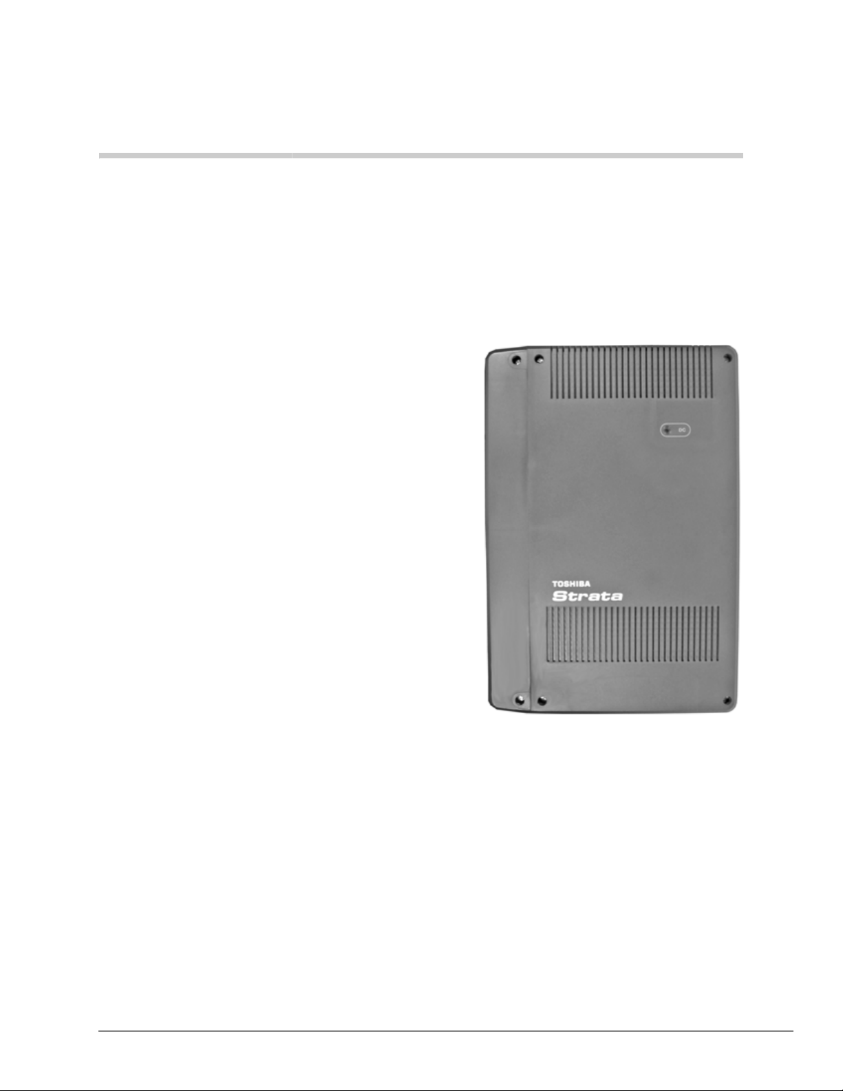
Strata CIX40 2
This chapter provides a system overview of the
Strata CIX40 telephone system.
The CIX40 is an IP communication system that
brings powerful IP telephony and Strata Net
networking capabilities to small customers and
branch office locations.
The Strata CIX40 system is a compact system that
provides large system features (for dimensions, see
Table 1). The CIX40 is designed for wall mounting
and occupies very little space.
An optional 4~8 port, 40-hour integrated plug and
play Toshiba Voice Processing system (GVPH1A)
with built-in modem plugs into a dedicated slot in
the Strata CIX40 cabinet. This integrated
combination of the Strata CIX40 and GVPH1A is a
very powerful and cost-effective small business
solution.
The plug and play CIX40 is easy and very cost
effective to install. The default plug and play
configuration is already programmed in the CIX40
and GVPH1A voice processing system. Any
additional programming or changes to the CIX40
can be done by using the latest version of eManager software that is found on Internet FYI.
The CIX40 can be configured with up to 24 IP channels to support Toshiba IP Desktop and Soft
phones; SIP telephones, SIP trunks and IP Strata Net channels to network multiple Strata CIX
systems.
The CIX40 easily connects to outside public and private telephone lines. All of the telephones
(stations) tied to the system can have direct access to each other, as well as to the public and
private network. All lines, stations, and options are tied together through the cabinet.
The CIX40 does not require processor licenses for analog Caller ID CO Lines, the first four Voice
Mail ports, digital or analog station ports, DTMF Receivers, etc. The only licenses needed are for
Voice Mail ports 5~8, IP Strata Net networking channels, Toshiba IP telephones, SIP phones SIP
trunks and Soft IP telephones connected to the optional
MIPU24-1A IP interface cards.
GIPU8, GIPH-X1A, MIPU16-1A and
Strata CIX General Description 04/13 3
Page 26
Strata CIX40
Processor
Licenses are required on the Media Application Server (MAS), Stratagy, SES, and customer
provided PCs for applications such as ACD, Strata Call Manager (SCM), TASKE, FeatureFlex,
VCS, Insight, etc.
The CIX40 comes with built-in circuitry for eight digital telephone ports, four CO line ports with
Caller ID Interface, one standard telephone port, built-in maintenance modem, LAN/NIC
interface, and one power failure transfer relay.
The Strata CIX40 system capacity can be expanded by adding the following expansion
components shown in parenthesis:
The fully expanded CIX40 system with optional interface cards provides the following capacities:
• 11 loop start CO line ports with Caller ID and 16 digital station ports (GCDU2A and
GCOCIH1A).
• Two standard telephone ports (GSTU1A).
• Eight, 16 or 24 IP channels for IP for any combination of telephone or Strata Net connection
(
GIPU8, GIPH-X1A, MIPU16-1A or MIPU24-1A).
• 4, 6 or 8 voice mail ports with 40 hours of message storage and 360 mailboxes (GVPH1A, LIC-
2 GVPH for 6 or 8 port).
• Four serial interface ports (BSIS).
The table below lists the CIX40 cabinet physical specifications
Table 1 CIX40 Cabinet Specifications
Cabinet Weight Height Width Depth
Cabinet (CHSU40A2)
The system cabinet is off-black and contains
the GMAU/GMAS motherboards
Processor
The Strata CIX40 processor (GCTU2A) is a standard part that plugs into a dedicated CIX40
cabinet slot.
The Strata CIX40 uses a high-speed 32-bit RISC processor, DRAM working memory, SRAM with
lithium battery to back-up memory.
The Strata CIX40 processor has the following standard components built-in:
• Secure Digital (SD) memory card interface for program data backup, software upgrades,
alarms, error logs, and admin logs done locally or remotely.
• Network Interface Card port provides one circuit for 100base-TX Ethernet LAN connection of
the eManager computer, ACD Server, CIX Attendant Console, Multimedia Application Server
(MAS) and CSTA applications.
• 33.6 Kbps/V.34 Factory installed AMDS1A ma intenance modem for connecting the eManager
administration tool locally or remotely.
6.6 lbs. 18 in. 12.2 in. 3.5 in.
• One Music-on-hold (MOH)/Background Music (BGM) RCA jack to interface with external
MOH and/or BGM sources. The CIX40 can have up to three MOH/BGM source interfaces by
adding two additional MOH/BGM input sources, connected to the Standard Telephone
interfaces.
4 Strata CIX General Description 04/13
Page 27
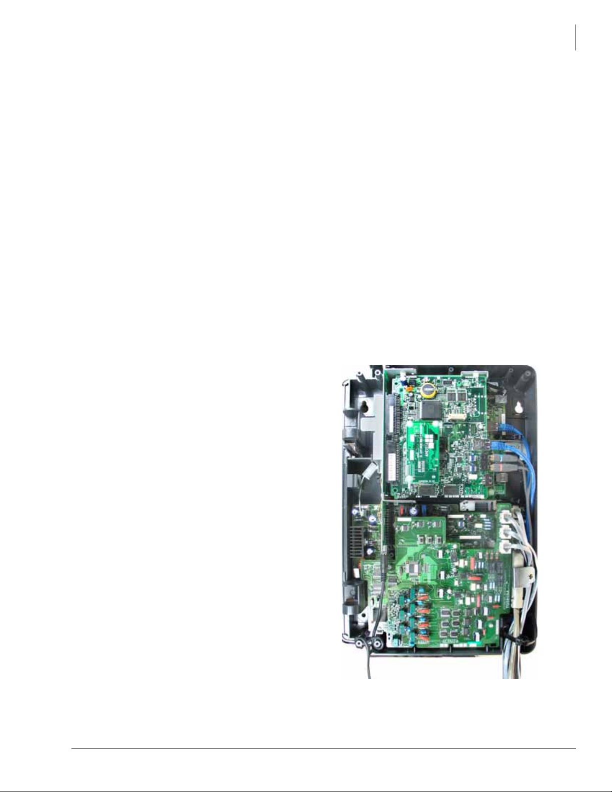
Strata CIX40
Figure 1 CIX 40 Interior
CIX40 Cabinet Slots
• One External Page RCA jack to interface with a Toshiba External Amplified Speaker (BESCB)
or a customer-supplied page amplifier and speaker(s) for extern al paging, night ring over
external page, and external BGM applications.
• One Relay control interface that provides an interface to a normally open relay contact which
can be programmed to control a Night Bell, door lock or to mute BGM during an external page.
• Memory Protection Battery that protects data and the customers programmed configuration
from memory loss. This information will be maintained in a powerless system for at least six
years.
• 16 DTMF receivers.
• 16 Busy Tone (BT) detector circuits for Auto Busy Redial (ABR).
• 64 conference circuits.
• Digital volume PAD technology enables audio volume to be adjusted in eight steps to
compensate for conference and/or CO line network losses.
The optional Serial Port Interface Subassembly (BSIS1A) can be installed on the processor to
provides RS-232 interface ports for SMDR interface to Call Accounting devices, SMDI for
external Voice Mail devices, and future applications. The BSIS1A is not needed for the GVPH1A
voice mail system because the GVPH1A uses built-in SMDI through the back plane.
CIX40 Cabinet Slots
The CIX40 Cabinet has three dedicated slots
used for the GCTU2A system processor card,
GVPH optional Voice Mail circuit card and a
slot that can add either four analog lines
(GCOCIH1A) or 8, 16 or 24 IP channels
(GIPU, GIPH, MIPU16 or MIPU24) optional
VoIP interface cards. All other CIX40 optional
interface cards plug onto the Processor or the
Motherboard. The CIX40 does not support
CIX1200/670/200/100 circuit cards.
Large Scale Integrated (LSI) Circuits (no licenses required)
The processor has an LSI circuit that supports
the following:
•16 DTMF receivers
• 16 Busy Tone (BT) detector circuits for
Auto Busy Redial (ABR)
• 64 built-in conference circuits
• Built-in, adjustable, digital volume PAD
technology enables audio volume to be
adjusted in eight steps to compensate for
conference and/or CO line network losses
Strata CIX General Description 04/13 5
Page 28

Strata CIX40
CIX40 Cabinet Slots
GCTU2A Processor Interfaces
Memory Protection Battery
If commercial AC power is lost or if a system is moved or stored without power, the processor has
an on-board battery that protects data and the customer’s programmed configuration from memory
loss. This information will be maintained in a powerless system for at least six years.
Relay Control Interface
An on-board terminal strip provides an interface to a normally open relay contact which can be
programmed to control a Night Bell, door lock or to mute BGM during an external page.
External Page Interface
A 600 ohm RCA jack is built into the processor to interface with a Toshiba External Amplified
Speaker Control box (BESCB) or a customer-supplied page amplifier and speaker(s) for external
paging, night ring over external page, and external BGM applications.
Music-on-hold/Background Music Interface
One 600-ohm RCA jack is provided on the processor to interface with Music-on-hold and/or
Background Music (BGM) sources. With the CIX40, you can have up to three MOH/BGM source
interfaces. The CIX40 Standard T elephone interfaces can be used to provide up to two MOH/BGM
input sources in addition to the processor MOH/BGM interface.
Secure Digital Memory
The processor has an on-board Secure Digital (SD) memory card slot. A SD memory card can be
inserted into the slot to backup and restore customer program data. It also makes it easy to upload
operating system data for software upgrades and is used to store maintenance log files.
CIX40 Processor Optional Subassembly
Optional subassembly can be attached to the GCTU2A processor to provide additional features.
The subassembly is:
BSIS (Serial Port Interface) – Provides up to two RS-232 interface ports for SMDR interface to
Call Accounting devices, SMDI for external Voice Mail devices, and two future applications.
Notes
• The GVPH does not require a BSIS SMDI port.
• The factory installed AMDS maintenance modem and Network Interface Card (NIC) come
built into the GCTU2A processor.
6 Strata CIX General Description 04/13
Page 29

GVPH – Integrated Voice Mail
With the release of Strata CIX40, Toshiba is also introducing a plug and play voice mail circuit
card (GVPH1A) specifically for the Strata CIX40 cabinet. It plugs into a dedicated cabinet slot and
requires no additional hardware to provide its full set of features.
The CIX40 is pre-programmed to match all related voice mail programming in the GVPH Voice
Mail system. This includes station numbers, mailboxes, voice mail hunt groups, voice mail station
IDs and many other items which are listed in the CIX40 installation documentation. The preprogrammed data is set when the processor is initialized even if the expansion cards or GVPH1A
Voice Mail system is not installed prior to system initialization.
It provides comprehensive Auto Attendant/Voice Mail capabilities, including the following:
• 4-Voice Ports (default) and 6 or 8 ports with LIC-2 GVPH license.
• 40 hours voice storage or up to 10,000 total messages.
• 360 mailboxes.
• Voice Mail Call Monitor – answering machine like operation to monitor and optionally pick-up
a call when someone is leaving a voice message.
• Voice Mail LCD Feature Prompting with Soft Key Operation (English and Spanish).
• Call Record – enables the user to record live calls.
Strata CIX40
GVPH – Integrated Voice Mail
• Installs in a dedicated CIX40 cabinet slot with SMDI integration built-in on backplane – no
serial port or other interface hardware is needed for interface or for its full set of features.
• Built-in remote maintenance modem.
• Administration requires the GVPH UADMIN2 Administration Software.
This is a new version of Stratagy UADMIN2 exclusively for the GVPH1A.
It also includes a new software version program update and prompt update capability for
remote maintenance.
• The Backup and Restore function stores Names, Greetings, Mail box numbers, and all other
database parameters. It does not back up/restore user messages.
• Pre-programmed with default mail boxes that match CIX40 default stations numbers, adding
simplicity to any installation.
T o program additional features beyo nd the default settings, refer to Strata CIX40 Voice Processing
Programming Manual and UADMIN2 software.
Feature Compatibility
The Strata CIX40 uses the same Release 5.10 software as Strata CIX100, CIX200 and CIX670
systems, so functionality and features are the same between them, with some exceptions that are
listed below.
The Strata CIX40 does not support the following capabilities:
• T1 and PRI digital trunk interfaces.
• DID, Ground start and Tie line analog trunk interfaces (supports Loop start with Caller ID).
• Dialed Number Identification Service (DNIS).
• Zone Page Interface.
• Analog Station: Caller ID, message waiting lamp control and off-premise stations
Strata CIX General Description 04/13 7
Page 30

Strata CIX40
System Configuration
System Configuration
Following are Strata CIX40 configuration guidelines:
• Pre-programmed to initialize and match CIX40 extension numbers with GVPH1A voice
mailboxes. So the system is ready for use when it is powered up the first time.
• Supports all CIX Release 5.2 and above features, except Speaker OCA and OCA on Digital
Telephones; T1 and PRI digital trunk interfaces; DID, Ground start and Tie line analog trunk
interfaces (supports Loop start with Caller ID), DNIS, and Zone Page Interface.
• Fully Licensed for 18 digital and analog telephones, 4 Voice Mail ports and 11 analog CO lines,
4 RS232 ports and 16-DTMF/ABR circuits. Licensing is only required for Strata Net
networking channels, IP telephones, SIP phones, SoftIPTs, 6 or 8 voice mail ports, and MAS
applications.
• Maximum Capacity is 16 Digital telephones, 11 Loop start lines with Caller ID Interface, 2
Standard telephone interfaces, 8 Voice Mail ports, 24 IP channels, and 4 RS-232 Serial
Interface ports.
• Digital Telephone Compatibility – Supports Toshiba DP5000-series telephones, Add-on
modules and DSS console. The DP5000-series telephones include a 10 button telephone set
(DP5022-SDM) that is designed as a cost-effective telephone for the CIX40.
• IP Telephone Compatibility – Supports all Toshiba 2000-series and 5000-series IP telephones,
Add-on-Modules and DSS consoles, SoftIPT soft phones on laptops and PDAs, and SIP
telephones.
• CO Line Compatibility – Loop start lines with or without Caller ID.
• Up to 24 IP SIP and Strata Net trunks are supported.
GVPH1A Voice Mail (optional plug in voice mail card):
• 4, 6 or 8 ports, 40 hours storage for saved messages, 360 mailboxes (4 default, 6 or 8 require
LIC-2 GVPH).
• W orks similar to IVP8R2 with additional features of Voice Mail Call Monitor , Voice Mail LCD
Feature Prompting with Soft Key Operation, and Call Record.
• Plugs into CIX40 dedicated cabinet slot.
• SMDI integration built-in on back plane – no serial port or other interface hardware needed.
• Built-in remote maintenance modem.
• Administration requires the GVPH UADM2 Administration Software. This is a new version of
Stratagy Admin exclusively for the GVPH1A.
• Pre-programmed with default mail boxes that match CIX40 default stations numbers, adding
simplicity to any installation.
8 Strata CIX General Description 04/13
Page 31
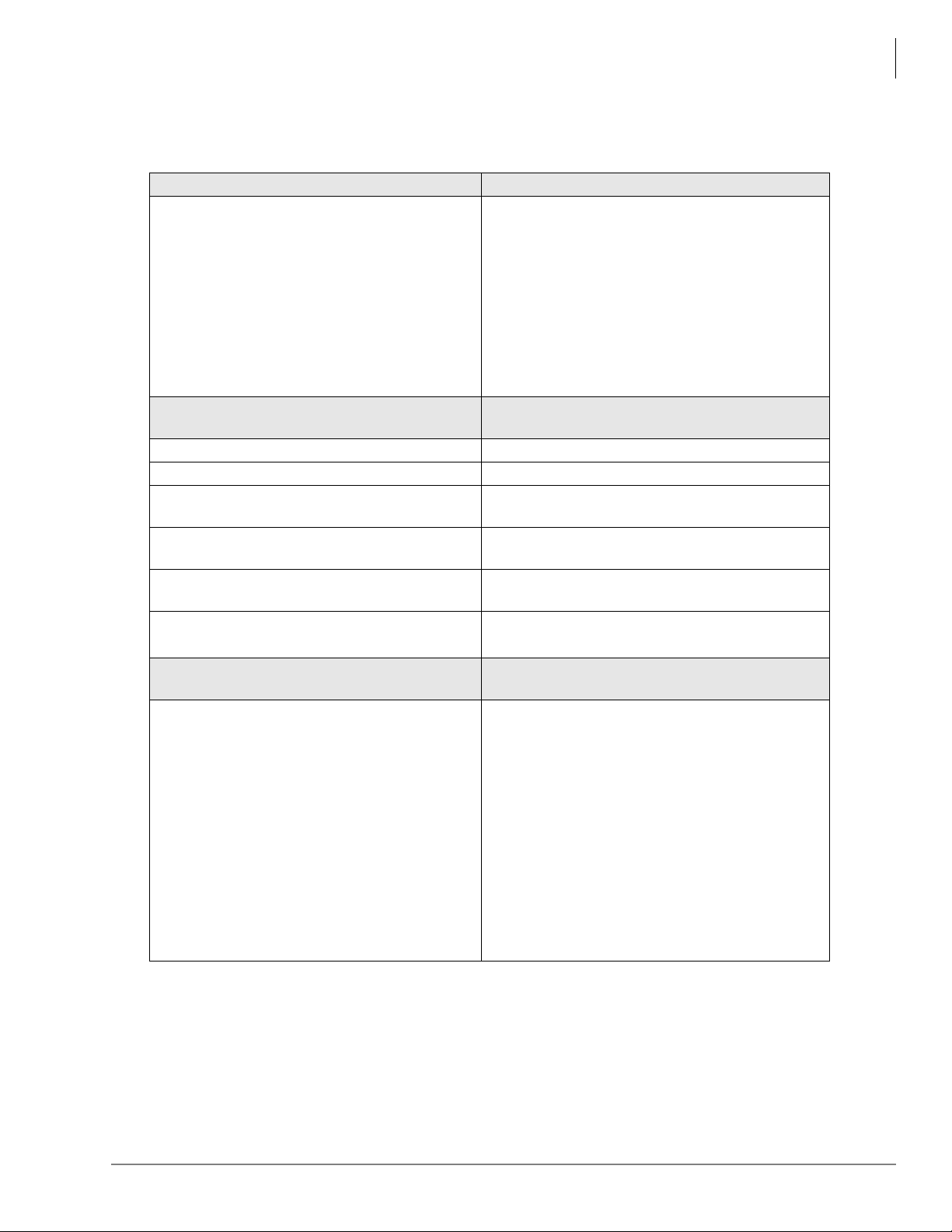
System Configuration
Table 2 CIX40 System Configuration
Basic Configuration - No Licenses Needed Basic Capacity
4 CO line w/CLID, 8 Digital Telephones and 1
Standard Telephone.
CHSU40A2 Cabinet, includes Power supply
and Mother Board. The CIX40 cabinet and
GCTU2A processor are boxed separa te ly. The
cabinet and processor are also warranted and
repaired separately.
Expanded Configuration – No Licenses
Needed
GCDU2A (3-CO line/8-DKT expansion card) 3 CO line w/CLID and 8 Digital telephones
GCOCIH1A (4 - CO expansion card) 4 CO lines with CLID
GVPH1A (voice mail plug-in card)
GSTU1A (standard telephone plu g -o n car d )
BSIS1A (4-port RS-232 interface plug-on card).
HPFB-6 one to two HPFB6 Battery with built-in
Chargers
Expanded Configuration – Licenses
Required
GIPU8-1A (8-channel GIPU IP plug-in card)
GIPH-X1A (8-channel IP plug-in card).
MIPU16-1A (16 channel IP plug-in card).
MIPU24-1A (24 channel IP plug-in card).
IP License requirements:
LIC-CIX-STRN-CH – one license required for
each IP Strata Net channel (Strata Net system
license is not available).
LIC-CIX-IP PORT – one license required for
each IP Telephone, SIP phone and SoftIPT.
LIC-SOFTIPT – one license required for each
SoftIPT.
Includes: 33.6 Kbps/V.34 Maintenance Modem,
Page interface, MOH interface, Control relay, 16
DTMF/ABR circuit, 1 Power Failure Transfer
interface, NIC port for 100base-TX Ethernet LAN
connection of eManager computer, ACD Server,
CIX Attendant Console, and CSTA applications,
and a Secure Digital card interface.
Capacity/Feature Option
4-port Toshiba Plug-in Voice Mail system
expandable to 6 or 8 ports with LIC-2 GVPH.
1 Standard Telephone (total 2 standard
telephones)
SMDR for Call Accounting or SMDI for external
voice mail system
Reserve Power (Battery Backup)
Expanded Capacity/Feature Option
Maximum 8, 16 or 24 channels for any mix of IP
telephones or Strata Net networking channels.
Strata CIX40
Note See the “CIX40 Functional Block Diagram” on page 12 to see how the circuit cards and
interface connectors can be used for connecting stations and peripherals.
Strata CIX General Description 04/13 9
Page 32
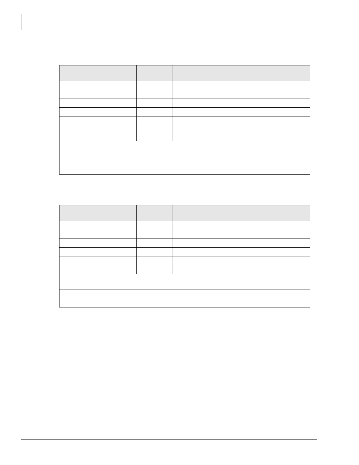
Strata CIX40
System Configuration
Table 3 CIX40 R2 Cabinet Configurations (CHSU40A2 Cabinet/R5.1 SW)
Analog
CO Lines
4 8 0 Cabinet (CHSU40A2)
7 16 0 Cabinet, GCDU2A
8 8 0 Cabinet, GCOCIH
11 16 0 Cabinet, GCDU2A, GCOCIH1A
4 8 8, 16, 24 Cabinet, GIPU, GIPH1A, MIPU161A, MIPU241A
7 16 8, 16, 24
Voice Mail: GVPH1A can be installed in all of the above configurations to provide 4 default VM
Ports and expand to 6 or 8 VM Ports with the LIC2-GVPH license
Analog FX/Modem Ports: One analog station port is st andard on the Base cabinet;
a second can be added by installing GSTU1A.
Table 4 CIX40 R1 Cabinet Configurations (CHSU40A Cabinet/R5.1 SW)
Analog
CO Lines
3 8 0 Cabinet (CHSU40A)
6 16 0 Cabinet, GCDU2A
7 8 0 Cabinet, GCOCIH
10 16 0 Cabinet, GCDU2A, GCOCIH1A
3 8 8, 16 Cabinet, GIPU8, GIPH1A, MIPU16
6 16 8, 16 Cabinet, GCDU2A, GIPU8, GIPH1A, MIPU16
Voice Mail: GVPH1A can be installed in all of the above configurations to provide 4 default VM
Ports and expand to 6 or 8 VM Ports with the LIC2-GVPH license
Analog FX/Modem Ports: One analog station port is st andard on the Base cabinet;
a second can be added by installing GSTU1A.
Digital
Telephones
Digital
Telephones
IP Channels Equipment
Cabinet, GCDU2A, GIPU, GIPH1A, MIPU16,
MIPU24
IP Channels Equipment
10 Strata CIX General Description 04/13
Page 33
Telephone and Console Support
Reserve Power
One or two HPFB-6 optional units can be added to the CIX40 to provide reserve power. The
amount of reserve power time depends on the hardware (see Table 5). The table below is an
estimate of battery backup time based on the premise that the HPFB-6 unit(s) are fully changed at
the time of AC power failure. This estimated backup time is based on normal call traffic, the time
estimates will be reduced by as much as half with extreme heavy traffic volumes.
Table 5 CIX40 Reserve Power Duration Estimates
Hardware 1 HPFB-6 2 HPFB-6
3CO/8DKT/DP - No GVPH 1 hr. 40 min. 3 hr. 20 min.
3CO/8DKT/DP - with GVPH 1 hr . 30 min 3 hr.
6CO/16DKT/DP - No GVPH 1 hr. 5 min. 2 hr. 10 min.
6CO/16DKT/DP - with GVPH 1 hr. 2 hr.
11CO/8DKT/DP - No GVPH 1 hr. 20 min. 2 hr. 40 min.
11CO/8DKT/DP - with GVPH 1 hr. 10 min. 2 hr. 20 min.
11CO/16DKT/DP - No GVPH 1 hr. 2 hr.
11CO/16DKT/DP - with GVPH 55 min. 1 hr. 50 min.
Strata CIX40
Note The CIX40 should be plugged into AC power and the DC power switch should be turned on
when installing the HPFB-6. The HPFB-6 will not start to operate if AC power is not
available during the initial installation.
Telephone and Console Support
The Strata CIX40 supports all current Toshiba 5000-series Telephones, Add-on Module, DSS
Console, and CIX Attendant Console. see Chapter 7 – Telephones and Peripherals.
The Strata CIX40 supports 3000-series and 3200-series digital telephones, including the
DKT3007-SD(W) and DKT3207-SD 7-button models, Add-on Module, DSS Console, CIX
Attendant Console, and generic single-line telephones (2500-sets). For details on Telephones and
Consoles, see Chapter 7 – Telephones and Peripherals.
The Strata CIX40 supports Toshiba 2000-series and 5000-series IP telephones, SoftIPT soft
phones on laptops and PDAs, and SIP telephones.
The Strata CIX40 does not support analog electronic telephones (6500-series, 6000-series, etc.) or
older IPT1020-SD IP telephones.
The Strata CIX40 supports CIX IP and Digital Attendant consoles.
Strata CIX General Description 04/13 11
Page 34
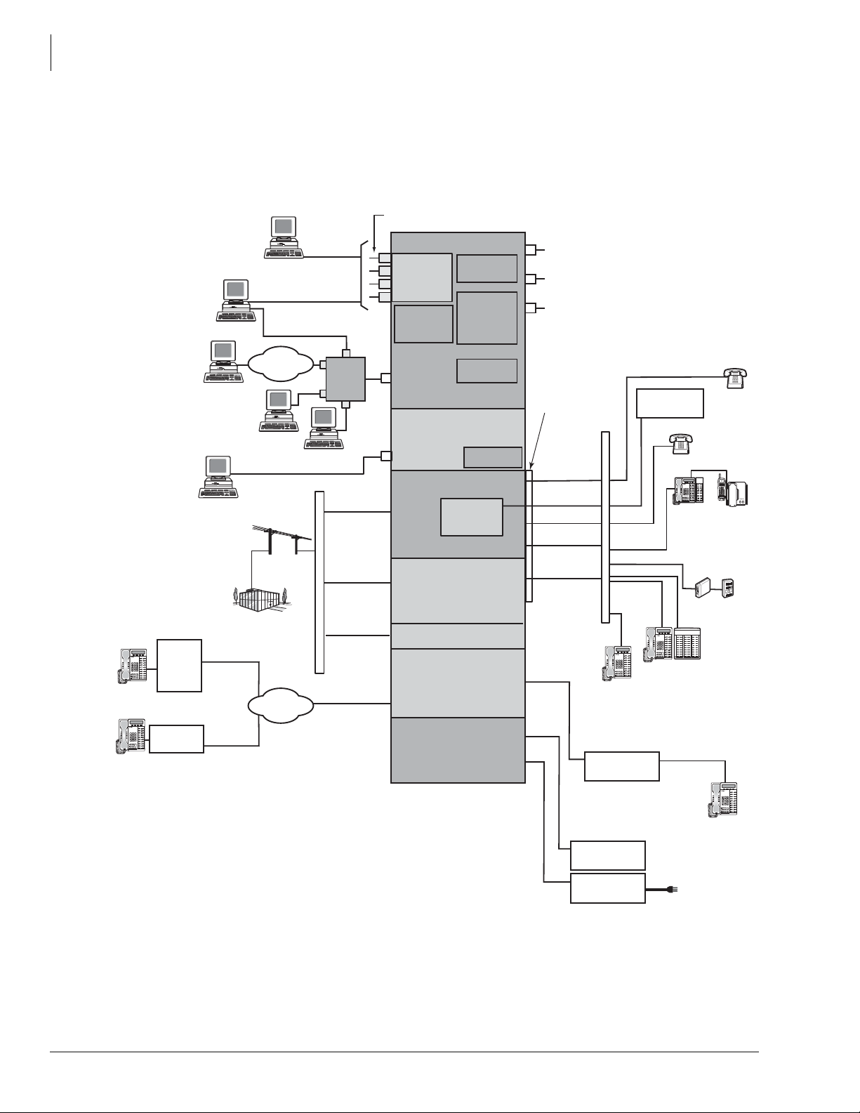
LAN
Digital
Telephone
(DP) and
Add-on
Module
DDCB
Cordless
DKT
Power Failure
Telephone
(Co Line 1)
MDFB
Door Phones and
Lock Controls
Standard
Telephone
1-Std. Tel. Circuit
1-Std. Tel. Circuit
25-pair
Amphenol
Connector
8-Digital Tel.
Circuit
8-Digital Tel.
Circuit
PFCT
Digital
Telephone
IPT 2000
IPT 2000
IPT 2000
Digital Telephone
with DSS Console
Page ScrollMode Feature
Msg
Mic Redial
Spdial
Spkr
Cnf/Trn
Hold
Vol
Page ScrollMode Feature
Msg
Mic Redial
Spdial
Spkr
Cnf/Trn
Hold
Vol
Page ScrollMode Feature
Msg
Mic Redial
Spdial
Spkr
Cnf/Trn
Hold
Vol
Page ScrollMode Feature
Msg
Mic Redial
Spdial
Spkr
Cnf/Trn
Hold
Vol
Page ScrollMode Feature
Msg
Mic Redial
Spdial
Spkr
Cnf/Trn
Hold
Vol
Page ScrollMode Feature
Msg
MicRedial
Spdial
Spkr
Cnf/Trn
Hold
Vol
0012-cix40c
GCTU2A
GVPH (optional)
Voice Mail/
Auto Attendant
Processor PCB
Up to Four Programmable Serial
(RS-232) Port Modular Jacks
Available
(RCA Jack) 600 ohm Interface to
Music On Hold and/or
Background Music Source
(RCA Jack) 600 ohm Interface to
External Paging Amplifier
(Relay Contact) for Night Relay,
Door Lock, or Page Mute
ACD
(CSTA)
RS-232 Maintenance port
SMDR
Call
Accounting
Remote CIX
eManager PC
Attendant
Console
Strata Net
IP End Point
BSIS
KSU Mother Board
GCDU2A
GIPH-X1A
GIPU8, MIPU16
MIPU24
8, 16 or 24 IP Channels
(Optional)
(Optional)
(Optional)
*
Conference
SW with PAD
Remote
Maintenance
Modem
Maintenance
Modem
MDF
KSU Mother Board
Power Circuit
Reserve Power
VoIP Channels
HPFB-6
Battery/Charger
120V AC, 60Hz
Ethernet
Interface
100Base TX
RJ45
DTMF/ABR
Receivers
SD Card
Maintenance
and
Customer
Database
WAN /
Internet
LAN
SMDI for
Toshiba Proprietary
Integration
Toshiba Proprietary
Soft Key LCD Link
Stratagy ES
Voice Mail
4-loop
start lines
with Caller ID
3-loop
start lines
with Caller ID
Network
Demarcation
Point
•
•
•
Central Office
Centrex
PBX
GSTU1A
(Optional)
FAX or Modem
UAdmin
CIX
Node
Router
AC Adaptor
WAN /
Internet
GCOCIH1A
(Optional)
*
4-loop
start lines
with Caller ID
*
If GCOCIH1A is installed, then GIPH-X1A,
MIPI16-1A or MIPU24-1A cannot be installed
and vice versa.
IP5000 /
IP5000 /
IP5000 /
Figure 2 CIX40 Functional Block Diagram
Strata CIX40
CIX40 Functional Block Diagram
CIX40 Functional Block Diagram
The Functional Block Diagram below shows the circuit cards and interface connectors used for
connecting the stations and peripherals to the CIX40 R2 cabinet (CHSU40A2).
12 Strata CIX General Description 04/13
Page 35
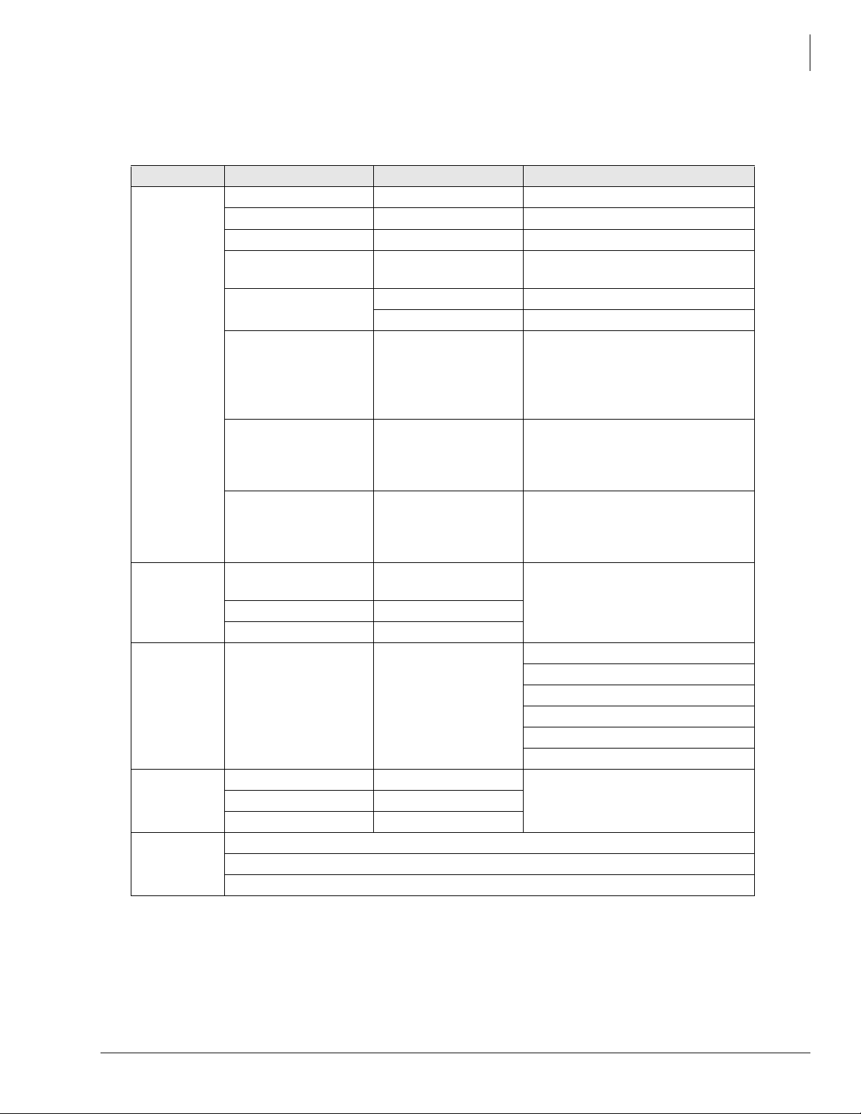
Additional Specifications
Table 6 CIX40 Specifications
Category Items Specification Remarks
Input voltage rating 100-240VAC
Input current rating 1.3A max. At full installation
Input frequency 50/60 Hz
Power
Environment
Safety
System
Regulation
FCC/ACTA
Registration
Numbers
AC adapter output
voltage
Voltage of inside
Power switch
Power failure back up
Grounding
AC Plug 2-pin (American)
Operating
Temperature
Operating humidity 20 - 80%
Storage temperature -20 - 60 C
Maximum ports 40 16: DP phones
Safety UL60950-1
Network Performance FCC part68
ACTA/FCC Part 68 Registration for Key System Code (KD): CJ6KD03BDTCHS402
ACT A/FCC Par t 68 Re gistration for Mult ifunction Code (MF): CJ6MF03BDTCHS402
ACTA/FCC Part 68 Registration for Multifunction Code (PF): CJ6PF03BDTCHS402
+15V/4.0A
-27.3V/+5.0V
DC Switch Located inside cabinet
1 HPFB6: 1 hour
2 HPFB6: 2 hours
See page 11
Customer supplied
Grounding wire.
0 - 40 C
Strata CIX40
Additional Specifications
The amount of time depends on
hardware configuration. One hour
in HPFB6 means 6 CO+16DP with
GVPH based on HPFB6 is fully
charged.
Ground wire must connect the
earth ground through the FG
terminal on the GMAU for safety
purposes and to protect noise.
Ground wire must connect the
earth ground through the FG
terminal on the GMAU for safety
purposes and to protect noise.
6: Analog trunk
8: IP channel
4: Voicemail
2: Analog devices
4: Serial ports
USAEMC FCC part15 class-A
Strata CIX General Description 04/13 13
Page 36
Strata CIX40
Station Loop Limits
Station Loop Limits
The table below provides the maximum loop limits for connection of telephones, lines, peripheral
equipment, and power supplies. The following information applies to only the Strata CIX40
system.
Digital Telephone/DIU/DDM Console/ADM/Loop Limits
Mode
DP5000, DKT3000, DKT3200-series or
DKT2000-series models, DP with BVSU
DVSU or BHEU or HHEU.
DKT with BPCI
DKT with BPCI and BHEU
DSS3060 or DSS2060
DDCB3A
BATI, RATI
DKT with 1 ADM
DKT with 2 ADMs
2
or
Maximum line
CIX40 Cabinet or
Battery Backup
CIX40 Cabinet 1000 303
Battery Backup 695 204
CIX40 Cabinet 1000 303
Battery Backup 500 151
CIX40 Cabinet 1000 303
Battery Backup 500 151
CIX40 Cabinet 1000 303
Battery Backup 675 204
CIX40 Cabinet 165 50
Battery Backup 500 151
CIX40 Cabinet 1000 303
Battery Backup 1000 303
CIX40 Cabinet 675 204
Battery Backup 165 50
CIX40 Cabinet 500 151
Battery Backup 33 10
1
length (24 AWG)
1 Pair
feet meters
1. Battery backup applies to instances when the system is being powered by batteries exclusively.
2. CIX40 Digital Telephones do not support Speaker OCA.
14 Strata CIX General Description 04/13
Page 37
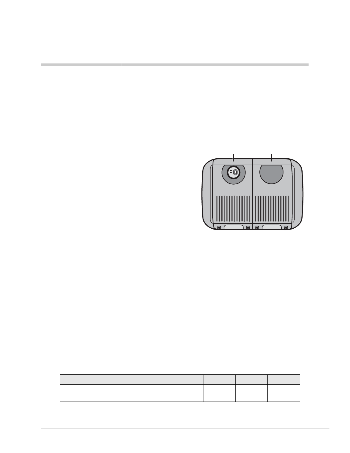
Strata CIX100-S / CIX100 3
Figure 3 CIX100-S / CIX100
Base / Expansion Cabinets
This chapter provides a system overview of the
Strata CIX100-S and CIX100 telephone systems.
Base Expansion
The Strata CIX100-S/CIX100 systems are
compact systems, yet they provide large system
features (see Figure 3 and Table 7). They are
designed for wall mounting and occupy very little
space.
The CIX100 processor (ACTU3A) comes with 32
ports (licensed) and can grow to 112 ports by
adding 4-port licenses.
The CIX100-S processor (ACTU3A-S) comes
with 16 ports (licensed) and can grow to 32 ports
by adding two eight-port licenses. Then, it can
5976
grow to 112 ports with four-port licenses.
Note The Strata CIX100-S and CIX100 system
capacities depend on the licenses stored on the system processor and the hardware described
in this chapter.
Important! The Strata CIX100-S uses the same hardware and configuration as the Strata
CIX100 with a few exceptions. Whenever the CIX100 is mentioned in this book, it
applies to both the CIX100-S and CIX100 unless specified otherwise.
Each ACTU3 basic processor can be configured with a one or two cabinet system. A single (Base)
cabinet system supports a combination of up to 64 Central Office (CO) lines and stations, while a
two cabinet system (Base and Expansion) can support up to 112 CO lines and stations.
System line and station capacity is expanded by adding CO line and station circuit cards and port
licenses into its universal slot architecture.
The CIX100 easily connects to outside public and private telephone lines. All of the telephones
(stations) tied to the system can have direct access to each other, as well as to the public and
private network. All lines, stations, and options are tied together through the cabinets.
Table 7 CIX100-S/CIX100 Cabinet Specifications
Base Cabinet (CHSUB112) 19.4 lbs. 14.6 in. 11.9 in. 10.2 in.
Base + Expansion Cabinet (CHSUE112) 34.6 lbs. 14.6 in. 19.9 in. 10.2 in.
1. Weight includes the processor card in the Base Cabinet and four universal circuit cards in each
cabinet.
Strata CIX General Description 04/13 15
Cabinet
Weight
1
Height Width Depth
Page 38

Strata CIX100-S / CIX100
CIX100-S and CIX100 Processors
CIX100-S and CIX100 Processors
Each system operates with one processor card (ACTU3A-S for CIX100-S, ACTU3A for CIX100)
that installs in a dedicated slot of the Base Cabinet. The processors incorporate the following
hardware features.
CPU/Memory
Either processor card uses a high-speed, 32-bit, RISC processor, Dynamic Random Access
Memory (DRAM) working memory , Static Random Access Memory (SRAM) with lithium battery
for memory back-up, and flash program memory.
Large Scale Integrated (LSI) Circuits
The processors each have LSI circuits that support the following:
• 16 DTMF receiver hardware processor are built into the ACTU3. Five or more DTMF
receivers require appropriate licenses.
• 16 Busy Tone (BT) detector circuits for Auto Busy Redial (ABR) are built into the ACTU3.
• 64 built-in conference circuits.
• Built-in, adjustable, digital, volume PAD technology enables audio volume to be adjusted in
eight steps to compensate for conference and/or CO line network losses.
Memory Protection Battery
If commercial AC power is lost or if a system is moved or stored without power, the processor has
an on-board battery that protects data and the customer’s programmed configuration from memory
loss. This information will be maintained in a powerless system for at least six years.
Relay Control Interface
An on-board terminal strip provides an interface to a normally open relay contact which can be
programmed to control a Night Bell or door lock or to mute BGM during an external page.
External Page Interface
A 600 ohm RCA jack is built into each processor to interface with a Toshiba External Amplified
Speaker (BESCB) or a customer-supplied page amplifier and speak er(s) for external paging, night
ring over external page, and external BGM applications.
Music-on-hold/Background Music Interface
A 600-ohm RCA jack and volume controls are built into each processor to interface with Musicon-hold and/or Background Music (BGM) sources (one of the jacks is for future use). With the
CIX100, you can have up to 15 MOH/BGM source interfaces by adding:
• Up to two BIOU circuit cards, each provides three MOH/BGM input sources
• An RSTU circuit card that provides up to eight MOH/BGM input sources
Secure Digital Memory
Each processor has an on-board SD memory card slot. A SD flash memory card can be inserted
into the slot to backup and restore customer program data. It also makes it easy to upload operating
system data for software upgrades and is used for maintenance functions (see “System Fault
Finding and Diagnostics” on page 175 for more details).
16 Strata CIX General Description 04/13
Page 39
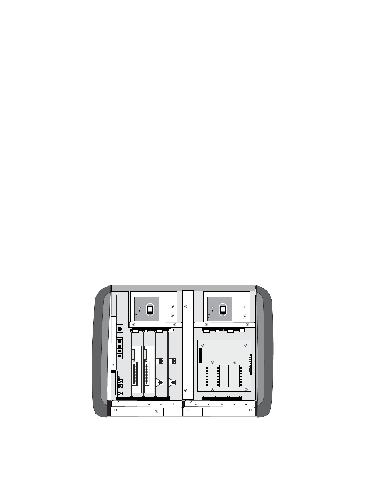
Strata CIX100-S / CIX100
CIX100 Cabinet Slots
Built-in Ethernet Connection
The ACTU processor has an on-board Ethernet 100Base-T Ethernet interface for connection to
Open Architecture Computer Telephony Interface (CTI) applications. This provides extensive call
control and telephone support for CTI applications. The Ethernet Network Interface Card (NIC)
port also enables connection to the following:
• CIX Attendant Console
•ACD server
• Local and Remote eManager PC
• Soft Key Control of Voice Mail features
CIX100 Processor Optional Subassemblies
Optional subassemblies can be attached to the ACTU3A-S or ACTU3A processors to provide
additional features. The subassemblies are:
• AMDS (Modem) – Provides a 33.6Kbps/V.34 modem for point-to-point local or remote
connection to the eManager administration PC.
• BSIS (Serial Port Interface) – Provides up to two RS-232 interface ports for SMDR interface
to Call Accounting devices, SMDI or Toshiba Proprietary interface to Voice Mail devices, and
two future applications.
CIX100 Cabinet Slots
Base Cabinet
The Base Cabinet has one dedicated slot used for the system processor card and four universal
slots (S101~S104), that can accommodate station, line or option circuit cards. It also houses a
power supply that is packaged with the cabinet.
Expansion Cabinets
One expansion cabinet has four universal circuit card slots (S105~S108) that can accommodate
station, line or option circuit cards. It also houses a power supply that is packaged with the cabinet.
DC POWER
DC
AC
DC POWER
DC
AC
TOSHIBA
AMAUE1A
S101 S102 S103 S104 S105 S106 S107 S108
TOSHBIA
D
IG
IT
A
L
BU
M
O
D
E
L
C
H
Strata CTX100
T
O
S
H
IB
A
COR
S
IN
E
S
S TE
L
E
S
U
B
1
1
2
A
V
I
N
P
P
ORA
T
I
ON
49L7
P
H
O
N
E
S
Y
S
CUS
T
E
M
E88891
1
A
.
N
O
R
10062
TIM
U
T
:
1
2
0
V
a
c
6
0
H
z
1
.
8
A
MA
D
E
I
N
M
AL
AY
SI
A
Z
C
P
TOSHBIA
D
IG
IT
A
L
BU
M
O
D
E
L
C
Strata CTX100
T
O
S
H
IB
A
COR
S
IN
E
S
S TE
L
E
P
H
O
N
E
S
Y
S
T
E
M
H
S
U
B
1
1
2
A
V
1
A
.
N
O
R
100
39
I
N
P
U
T
:
1
2
0
V
a
c
6
0
H
z
1
.
8
A
P
ORA
T
I
ON
MA
D
E
I
N
MAL
AY
SI
A
Z
C
P
6576
Figure 4 Base and Expansion Cabinet Interior
Strata CIX General Description 04/13 17
Page 40

This page is intentionally left blank.
Page 41
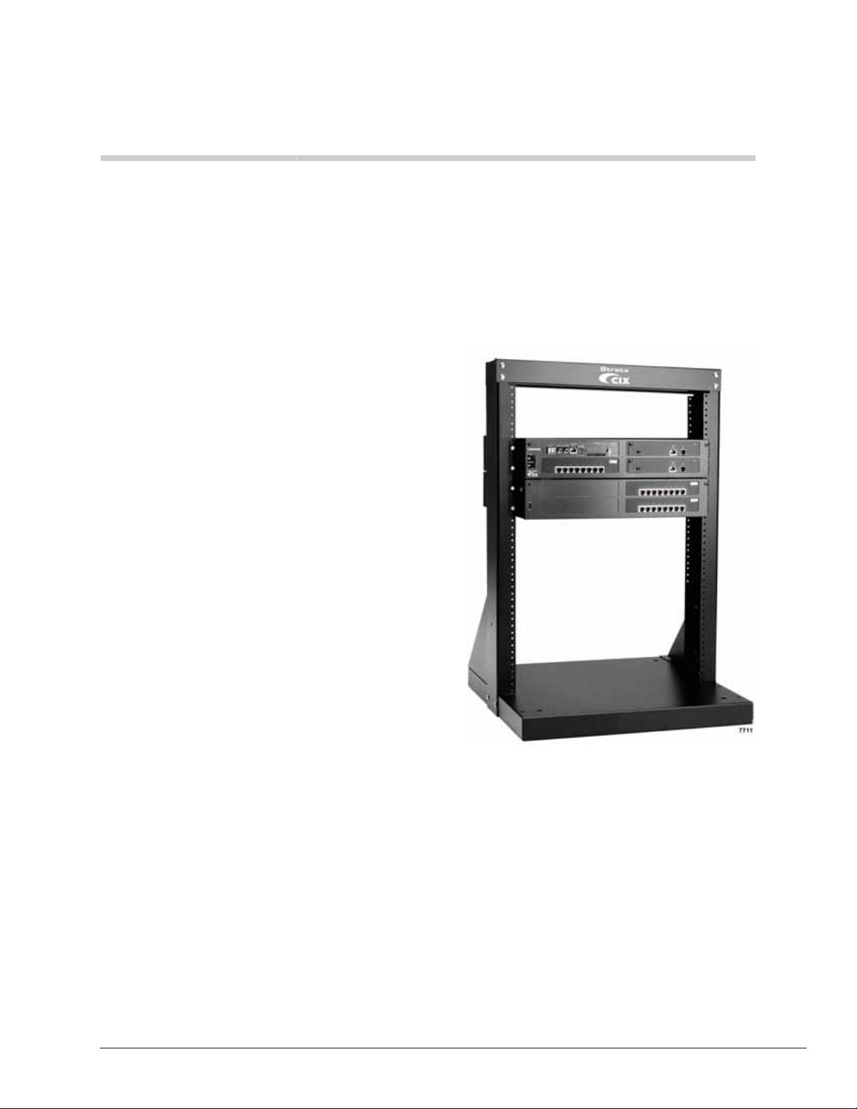
Strata CIX200 4
The Strata CIX200 supports 192 ports and can b e
configured as a one or two cabinet system,
consisting of a Base Cabinet and one optional
Expansion Cabinet. One processor model
supports all Strata CIX200 configurations from
smallest to largest.
These cabinets are designed specifically to fit
standard (customer-supplied) 19” racks. The 19”
rack and rack screws must be supplied by the
dealer. Interface cables connect directly to the
front panel or exit the cabinet through a port on
the right side of the cabinet.
The CIX200 uses a single-card common control
processor unit (LCTU2A), with a high-speed 32bit RISC processor, 64 MB DRAM working
memory, SRAM with lithium battery on-board
flash program memory, and removable Toshiba
Secure Digital flash memory.
Base Cabinet
The Base Cabinet (CHSUB192A) has four slots. The upper left slot, labeled B101 is reserved for
the common control unit. The other three slots (labeled S101, S102 and S103) are universal card
slots capable of hosting any of the station, line, and option interface PCBs compatible with the
Strata CIX systems. The Base Cabinet also has a dedicated LSLU slot located at the back of the
cabinet for two analog ports with two connectors on the front of the cabinet.
Expansion Cabinets
One Expansion Cabinet (CHSUE192A) can be added to increase the system station and CO line
capacity. The Expansion Cabinet has four universal slots for interface cards (labeled S201 ~ S204).
Compatible interface cards include the MIPU / LIPU / LIPS IP interface cards and the current
Strata CIX interface cards that support CO lines, digital telephones, analog stations, etc.
Refer to “Capacities” on page 209 for cabinet slot and station/line capacities.
Strata CIX General Description 04/13 19
Page 42
Strata CIX200
Basic Specifications
Basic Specifications
The following table lists the parts and basic specifications of the CIX200 Rack Mount Cabinets.
Dimensions of each
cabinet – Base
(CHSUB192A) and
Expansion (CHSUE192A)
Power Supply Unit (PSU) Initially Built-in
19" Rack Installation
Dimension
Installation
Power Backup
An Uninterruptible Power Supply (UPS) is required for power backup on a CIX200. The UPS is
similar to the ones used for computer systems and networking equipment.
Height: 2U or 3.5 inches (88.9 mm)
Width: 17.3 inches (440mm – without bracket);
19 inches (483 mm – with bracket)
Depth: 16.1 inches (410mm)
Weight: 16 lbs (7.2 kilograms)
IEC297-1 (EIA RS 310-D)
465.1mm (front face screw pitch – width)
Rack-mount (preferred) or Table top.
Important! Do not place the equipment on the floor or in a dusty place.
20 Strata CIX General Description 04/13
Page 43
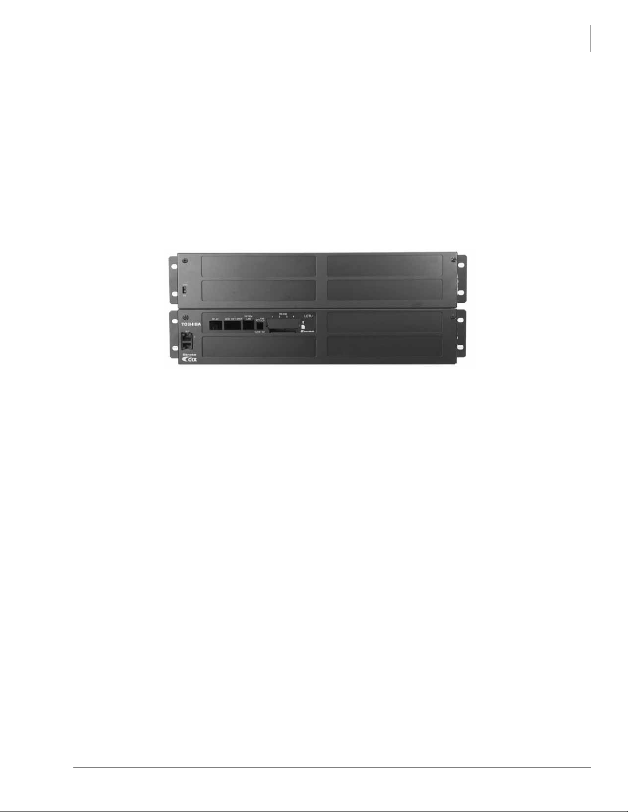
Configuration
Base Cabinet
Expansion
Cabinet
Processor
Card
The two primary considerations in system configuration are Card Slot Use and Power Factor.
Card Slot Use
The card slots can each support up to 32 ports. There are a few card position requirements based
on cable lengths. These are discussed in detail in the Strata CIX Installation Manual. These
requirements do not affect the system capacities.
In general, determine the number and type of stations needed, the number and typ e of trunks, and
any additional requirements. Other requirements include voice mail, power fail transfer, tie lines,
etc. The total number of ports required must not exceed 192.
Strata CIX200
Configuration
Figure 5 Two Cabinet CIX
Power Factor
Power Factors for the CIX200 circuit cards are shown below. For all others please refer to the
Installation and Maintenance Manual.
• LCTU1A: No effect on Power Factor calculations
• MIPU: PF = 0.2
• LIPU-X1A: PF = 2.6
• LIPS-X1A: PF = 1.9
• LSLU1A: PF = 1.5
There are no Power Factor considerations for the new IP Telephones (IPT2010/2020/2008), addon modules (IADM2020 and IDSS2060), and DSS consoles because the power is not supplied
from CIX200 cabinet.
The system (-24V) Power Factor is 67 per cabinet. There is no +5V power factor consideration for
the CIX200. For an example on how to use the System Power Factor and for worksheets, refer to
the Strata CIX Installation and Maintenance manual.
7530
Strata CIX General Description 04/13 21
Page 44

Strata CIX200
CIX200 PCBs
CIX200 PCBs
Two circuit cards are specific to the CIX200 systems; the LCTU processor card and the LSLU, a
two-circuit, single-line, telephone interface card. The MIPU24 IP interface card with 24 channel
works with the CIX200. The LIPU, an IP interface with 16 resources expands to 32 with the LIPS
expansion card and works on all CIX systems.
PCB Option Considerations
Strata CIX PCBs can be configured for a variety of hardware and software options. Hardware
options are defined as either internal (generally related to optional PCB subassemblies) or external
(related to connection of peripheral equipment such as background music, voice mail, etc.).
Some PCBs must have hardware options, such as jumpers or switches, set prior to installation of
the PCB in the cabinet.
Common Control Processor Unit (LCTU)
The system operates with the LCTU2A processor PCB that installs in a dedicated slot of the Base
Cabinet. The Strata CIX200 processor has the following standard components built in:
• Secure Digital (SD) memory card interface. A SD flash memory card can be inserted to backup
and restore customer program data. It also makes it easy to upload operating system data for
software upgrades and maintenance functions.
Note LCTU1A uses Smart Media (SM) flash memory.
• One Music-on-hold/Background Music Interface is provided by an RCA jack and a volume
control that are built into the processor to interface with a Music-on-hold and/or Background
Music source. Up to 15 MOH/BGM sources are supported by adding up to two BIOU option
cards, each provides three MOH/BGM input sources, and a BSTU card that provides up to
eight MOH/BGM input sources. MOH/BGM source volume adjustment is controlled by
software programming.
• Network Interface Card (NIC) Ethernet 100Base-T Ethernet port for IP management and
connection to Open Architecture Computer Telephony Interface (CSTA) applications. This
provides extensive call control and telephone support for CTI applications.
• 16 built-in DTMF receivers (five or more DTMF receivers require licenses).
• 16 built-in Busy Tone (BT) detectors for Auto Busy Redial (ABR).
• 64 built-in conference circuits.
• Built-in, adjustable, digital volume PAD technology enables audio volume to be adjusted in
eight steps to compensate for conference and/or CO line network losses.
• Page connector – External Page interface.
• Relay connector – Relay Control interface.
• Memory Protection Lithium Battery that protects data and the customer’s programmed
configuration from memory loss. This information will be maintained in a powerless system for
at least six years.
Optional subassemblies can be added to the LCTU processor PCB to enable system expansion and
provide additional features. The subassemblies are:
BSIS interface PCB attaches to the LCTU to provide up to four RS-232 interface ports for
SMDR Call Accounting, and SMDI or Toshiba Proprietary Voice Mail interface.
AMDS (Modem) – Provides a 33.6Kbps/V.34 modem for point-to-point local or remote
connection to the eManager administration PC.
22 Strata CIX General Description 04/13
Page 45

Analog Standard Station Interface Unit (LSLU1A)
The optional 2-circuit LSLU card provides for connection of two analog devices, such as faxes,
modems, standard telephones, etc., without message waiting. The LSLU installs into a dedicated
mount in rear of Strata CIX Base Cabinet behind the processor slot. The LSLU does not occupy
any of the universal slots of the cabinet, so it does not reduce the maximum capacity of the system.
The two analog station ports are accessible on the front of the base cabinet via modular connectors.
Modular or Amphenol Connections
The Strata CIX200 provides a choice of using either RJ45 modular connectors or amphenol
connectors for terminating CO line and station interfaces.
• Modular connectors provide an IT friendly environment using RJ45 cables and patch panel
connections in data racks.
• Amphenol connectors provide efficient connection to existing voice cables terminated on the
wall on 110 or 66 blocks.
• Either way , the installation technician can exercise his preference or the customer’s preference
for the type of connection that will take less time to install or save the customer money.
Modular RJ45 connectors are provided by adding optional extenders and modular faceplates to
CIX interface cards used in the Strata CIX200. This enables the modular interface cables to be
connected at the front panel of the CIX200 cabinet.
Strata CIX200
Modular or Amphenol Connections
Amphenol connectors are provided by using CIX interface cards in the Strata CIX200 without
extender cards. In this configuration, amphenol interface cables are routed through the side of the
cabinet and a flat face plate covers the slot housing the card. See the Strata CIX Installation and
Maintenance Manual for more details on Modular or Amphenol co nnections.
The Strata CIX200 supports two different types of optional extenders for the other CIX interface
cards, depending upon the type of connectors that exist on the card.
Extenders
The CIX system uses two types of extenders. One type is connected between the interface card and
the cabinet backplane. This type of extender brings the interface connectors to the front of the
cabinet. The correct front plate for the interface card is packaged with the extender. These
extenders are optional.
The second type of extender plugs into the interface card front connector and presents different
connectors to the front plate. Some of this type are optional, such as the extender that connects to
the 25-pair Amphenol connector on the station card and presents eight or 16 modular connectors to
the front panel. Refer to Table 8.
Power Failure Transfer Unit (LPFU1A)
The optional 8-circuit LPFU card when used with the RCOU and RSTU cards can automatically
connect the CO line circuits to the Single Line Telephones (SLT) when system power fails. The
LPFU card installs onto the CO line card as an extender, so it shares the same cabinet slot. The
RCOU card must be in the slot above.
Strata CIX General Description 04/13 23
Page 46
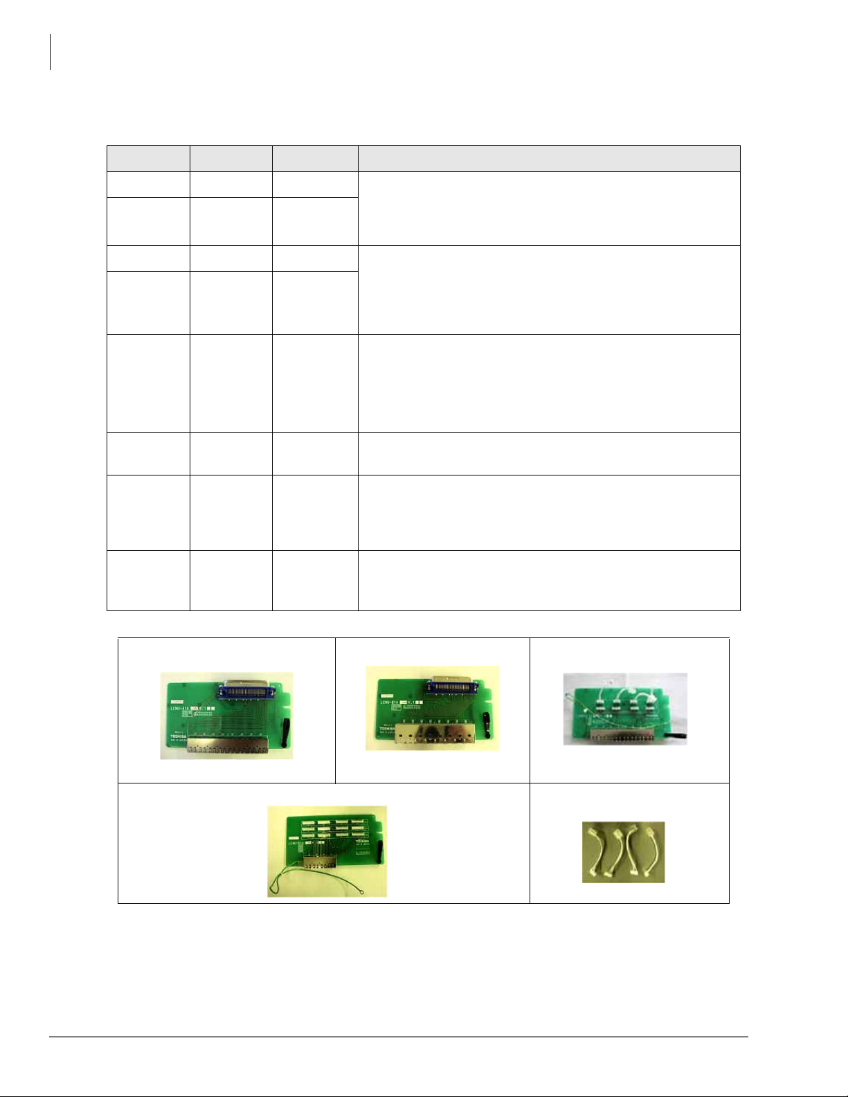
Strata CIX200
Modular or Amphenol Connections
LCNU-A1A, LCNU-B1A, LCNU-C1A, LCNU-D1A, LEXU, and LCNU-E1A
Table 8 CIX Extender Use
Extender Used For Required Comments
LEXU-A1A LIPU/MIPU Optional
LEXU-B1A
LCNU-A1A BSTCIU1A Optional
BPTU1A
RDTU3A
Optional
Extender installed between card and chassis backplane.
Interface card connectors are bought to the cabinet face.
BWDKU1A
LCNU-B1A
LCNU-C1A
LCNU-D1A REMU1A Optional
LCNU-E1A RCIU2A
LPFU1A
BDKU/
BDKS
RCOU3A
RGLU3A
RDDU2A
BCOCIU1A
Power Fail
Transfer
LCNU-A1A
Optional
Optional
(See
Comments
Required
(See
Comments)
Required
Plugs into the 50-pin Amphenol socket on the interface card.
Extends modular connectors to the CIX200 chassis face.
Plugs into the modular connectors on the interface card.
Extends modular connectors to the CIX200 chassis face.
The LCNU-C1A connects the CO lines and Caller ID in one
connector. If not used the connections must made on the
MDF.
Plugs into the modular connectors on the interface card.
Extends modular connectors to the CIX200 chassis face.
The LCNU-E1A is a set of small cables. These are required
only if the LCNU-C1A is used. Connects RCIU2A to the
LCNU-C1A to connect the Caller ID and CO line together in
one modular socket.
Required for power fail transfer operation. The LPFU1A is
two extender cards and two cables. The CO and Station
cards must be in adjacent slots.
LCNU-B1A LCNU-C1A
LCNU-D1A
LCNU-E1A
24 Strata CIX General Description 04/13
Page 47
Strata CIX670 and CIX1200 5
Figure 6 CIX 670 Base/
Expansion Cabinets
Strata CIX670
The Strata CIX670 system provides sophisticated
telecommunication features in a modular system
designed for growth. Its universal slot architecture
enables you to select the combination of Central Office
(CO) lines, stations, and peripheral options that best suit
your needs.
The CIX670 BCTU basic processor can be configured
for smaller systems as a one or two cabinet system with a
capacity of up to 192 CO lines and stations combined. It
can expand to support up to seven cabinets with a
capacity of up to 672 CO lines and stations combined
with the BCTU/BEXU expanded processor (see
Figure 6).
System line and station capacity is expanded by adding
processor expansion Circuit Cards, cabinets and line/
station circuit cards and station/line licenses.
The CIX670 easily connects to outside public and
private telephone lines. All of the telephones (stations)
tied to the system can have direct access to each other as
well as to the public and private network.
The Base Cabinet and optional Expansion Cabinets are
the building blocks of the system. Each system has a
Base Cabinet, and can have from one to six Expansion
Cabinets. All lines, stations, and options are tied together
through the cabinets. There are two types of cabinets,
floor/wall mountable and rack mountable. See page 32 for details on rack mountable cabinets.
The overall weight and dimensions of the CIX670 cabinets are shown in Table 9.
Table 9 CIX670 Floor/Wall Mount Cabinet Specifications
Cabinet Weight Height Width Depth
Base Cabinet (CHSUB672) 31 lbs. 11.625 in. 26.5 in. 10.3 in.
Expansion Cabinet (CHSUE672) 29 lbs. 9.75 in. 26.5 in. 10.3 in.
5398
Strata CIX General Description 04/13 25
Page 48

Strata CIX670 and CIX1200
CIX670 Processor Circuit Cards
CIX670 Processor Circuit Cards
The system operates with the BCTU only or the BCTU and BEXU processor circuit cards that
install in dedicated slots of the Base Cabinet. The BCTU and BEXU processor incorporates the
following on-board hardware features:
CPU/Memory
The CIX670 uses a high-speed, 32-bit, Reduced Instruction Set Computing (RISC) processor,
Dynamic Random Access Memory (DRAM) working memory, Static Random Access Memory
(SRAM) with lithium battery for back-up memory and flash program memory.
Large-scale Integrated (LSI) circuits
The processor has LSI circuits that support the following:
• BCTU provides 16 built-in DTMF receivers; 32 available using the BCTU and BEXU. For five
or more DTMF receivers, appropriate licenses are required.
• BCTU provides 16 built-in Busy Tone (BT) detectors for Auto Busy Redial (ABR); 32
available using the BCTU and BEXU.
• BCTU provides 64 built-in conference circuits; up to 96 conference circuits are available using
the BCTU and BEXU.
• Built-in, adjustable, digital volume PAD technology enables audio volume to be adjusted in
eight steps to compensate for conference and/or CO line network losses.
Memory Protection Battery
If commercial AC power is lost or if a system is moved or stored without power, the processor has
an internal battery that protects data and the customer’s programmed configuration from memory
loss. This information will be maintained in a powerless system for at least six years.
Music-on-hold/Background Music Interface
An RCA jack and volume control are built into the processor to interface with a Music-on-hold
and/or Background Music source. With the CIX670, you can have up to 15 MOH/BGM sources by
adding:
• Up to two BIOU circuit cards, each provides three MOH/BGM input sources.
• A BSTU or any analog station card that provides up to eight MOH/BGM input sources.
• MOH/BGM source volume adjustment is controlled by software programming.
Secure Digital (SD) Memory
The BCTU processor has an on-board Secure Digital card slot. A SD flash memory card can be
inserted to backup and restore customer program data. It also makes it easy to upload operating
system data for software upgrades and is used for maintenance functions (see “System Fault
Finding and Diagnostics” on page 175 for more details).
26 Strata CIX General Description 04/13
Page 49

Strata CIX670 and CIX1200
CIX670 Processor Circuit Cards
Network Interface
The BCTU processor has an on-board Ethernet 100Base-T Ethernet interface for connection to
Open Architecture Computer Telephony Interface (CTI) applications. This provides extensive call
control and telephone support for CTI applications. The Ethernet Network Interface Card (NIC)
port also enables connection to the following:
• CIX Attendant Console
•ACD server
• Local and Remote eManager PC
• Soft Key Control of Voice Mail features
• Media Application Server (MAS)
CIX670 Processor Optional Subassemblies
Optional subassemblies can be added to the BCTU processor card to enable system expansion and
provide additional features. The subassemblies are:
• AMDS (Modem) – Attaches to the BCTU to provide a 33.6Kbps/V.34 modem for point-topoint local or remote connection to the eManager administration PC.
• BSIS interface card which attaches to the BCTU to provide up to four RS-232 interface ports
for SMDR Call Accounting and SMDI or Toshiba Proprietary Voice Mail interface.
Strata CIX General Description 04/13 27
Page 50
Strata CIX670 and CIX1200
CIX1200_BE
CIX 1200 Base/Expansion Cabinets
Strata CIX1200
Strata CIX1200
The Strata CIX1200 system provides
sophisticated telecommunication features in a
modular system designed for growth. Its
universal slot architecture enables you to
select the combination of Central Office (CO)
lines, stations, and peripheral options that
best suit your needs.
The CIX1200 HCTU basic processor can be
configured for smaller systems as a one or
two cabinet system with a capacity of up to
192 CO lines and stations combined. It can
expand to support up to seven cabinets with a
capacity of up to 672 CO lines and stations
combined with the HCTU/HEXAU expanded
processor. This configuration provides the
same number of ports as the CIX670.
However, it provides expanded feature
capacity for items such as LCR tables,
Network routing tables, etc.
The Strata CIX1200 can expand to support
twelve cabinets (shown right) with a capacity
of up to 1,152 CO lines and stations
combined with the HCTU/HEXBU expanded
processors.
System line and station capacity is expanded
by adding processor expansion circuit cards,
cabinets and line/station circuit cards and station/line licenses.
The CIX1200 easily connects to outside public and private telephone lines. All of the telephones
(stations) tied to the system can have direct access to each other as well as to the public and private
network.
The Base Cabinet and optional Expansion Cabinets are the building blocks of the system. Each
system has a Base Cabinet, and can have from one to 11 Expansion Cabinets. All lines, stations,
and options are tied together through the cabinets. There are two types of cabinets, floor/wall
mountable and rack mountable. See page 32 for details on rack mountable cabinets.
The overall weight and dimensions of the CIX1200 cabinets are shown in Table 10.
Table 10 CIX1200 Floor/Wall Mount Cabinet Specifications
Cabinet Weight Height Width Depth
Base Cabinet (CHSUB672) 31 lbs. 11.625 in. 26.5 in. 10.3 in.
Expansion Cabinet (CHSUE672) 29 lbs. 9.75 in. 26.5 in. 10.3 in.
28 Strata CIX General Description 04/13
Page 51

CIX1200 Processor Circuit Cards
The system operates with the HCTU (2 cabinets) only or the HCTU and HEXAU (7 cabinets) or
HCTU and HEXBU (12 cabinets) processor circuit cards that install in dedicated slots of the Base
Cabinet. The processor cards incorporate the following on-board hardware features:
CPU/Memory
The CIX1200 uses a high-speed, 32-bit, Reduced Instruction Set Computing (RISC) processor,
Dynamic Random Access Memory (DRAM) working memory, Static Random Access Memory
(SRAM) with lithium battery for back-up memory and flash program memory.
Large-scale Integrated (LSI) circuits
The processor has LSI circuits that support the following:
• HCTU provides 16 built-in DTMF receivers; 32 available using the HCTU and HEXAU and
48 using the HCTU and HEXBU. For five or more DTMF receivers, appropriate licenses are
required.
• HCTU provides 16 built-in Busy Tone (BT) detectors for Auto Busy Redial (ABR); 32
available using the HCTU and BEXAU and 48 using HCTU and HEXBU.
Strata CIX670 and CIX1200
CIX1200 Processor Circuit Cards
• HCTU provides 64 built-in conference circuits; up to 96 conference circuits are available using
the HCTU and HEXAU and up to 128 conference circuits using HCTU and HEXBU.
• Built-in, adjustable, digital volume PAD technology enables audio volume to be adjusted in
eight steps to compensate for conference and/or CO line network losses.
Memory Protection Battery
If commercial AC power is lost or if a system is moved or stored without power, the processor has
an internal battery that protects data and the customer’s programmed configuration from memory
loss. This information will be maintained in a powerless system for at least six years.
Music-on-hold/Background Music Interface
An RCA jack and volume control are built into the processor to interface with a Music-on-hold
and/or Background Music source. With the CIX1200, you can have up to 15 MOH/BGM sources
by adding:
• Up to two BIOU circuit cards, each provides three MOH/BGM input sources.
• A BSTU or any analog station card that provides up to eight MOH/BGM input sources.
• MOH/BGM source volume adjustment is controlled by software programming.
Secure Digital (SD) Memory
The HCTU processor has an on-board Secure Digital card slot. A SD flash memory card can be
inserted to backup and restore customer program data. It also makes it easy to upload operating
system data for software upgrades and is used for maintenance functions (see “System Fault
Finding and Diagnostics” on page 175 for more details).
Strata CIX General Description 04/13 29
Page 52

Strata CIX670 and CIX1200
CIX1200 Processor Circuit Cards
Network Interface
The HCTU processor has an on-board Ethernet 100Base-T Ethernet interface for connection to
Open Architecture Computer Telephony Interface (CTI) applications. This provides extensive call
control and telephone support for CTI applications. The Ethernet Network Interface Card (NIC)
port also enables connection to the following:
• CIX Attendant Console
•ACD server
• Local and Remote eManager PC
• Soft Key Control of Voice Mail features
• Media Application Server (MAS)
CIX1200 Processor Optional Subassemblies
Optional subassemblies can be added to the HCTU processor card to enable system expansion and
provide additional features. The subassemblies are:
• AMDS (Modem) – Attaches to the HCTU to provide a 33.6Kbps/V.34 modem for point-topoint local or remote connection to the eManager administration PC.
• BSIS interface card which attaches to the HCTU to provide up to four RS-232 interface ports
for SMDR Call Accounting and SMDI or Toshiba Proprietary Voice Mail interface.
30 Strata CIX General Description 04/13
Page 53
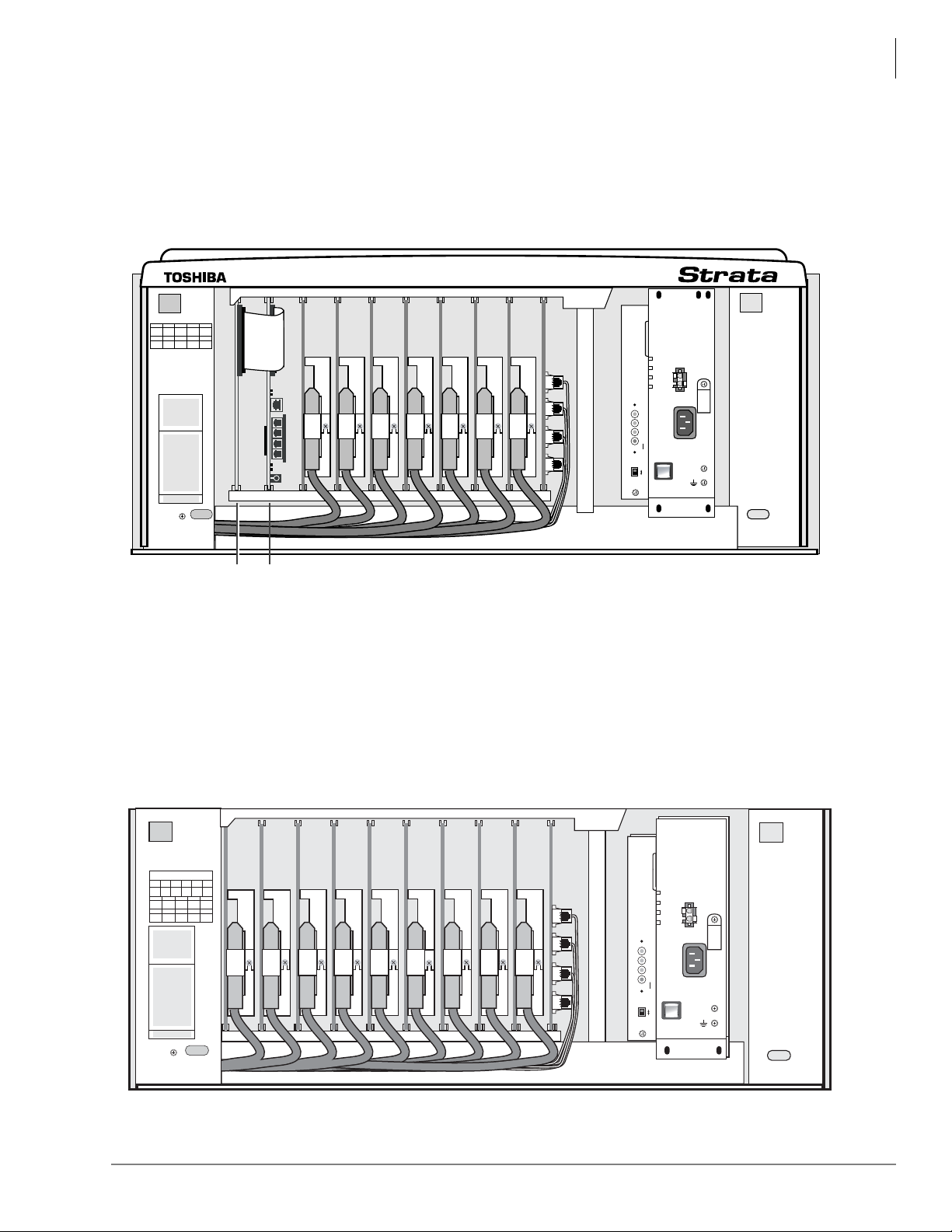
CIX670 and CIX1200 Cabinet Slots
POW
+5V
-5V
P.F.
RESET
EXP
BASE
AC IN
BATT
DC OUT
-24V1
-24V2
-24V3
-24V4
+
-
POWER
ON
OFF
FG
5002
B101 B102 S101 S102 S103 S104 S105 S106 S107 S108
6965
B101 B102 S101 S102 S103
S104 S105 S106 S107 S108
xEXU
xCTU
S_01 S_02 S_03 S_04 S_05 S_06 S_07 S_08 S_09 S_10
5003
CABINET NO.
2
S_01 S_02 S_03 S_04 S_05
S_06 S_07 S_08 S_09 S_10
34567
POW
+5V
-5V
P.F.
RESET
EXP
BASE
AC IN
AC IN
DC OUT
-27V1
-27V2
-27V3
-27V4
+
-
POWER
ON
OFF
FG
5002
POW
+5V
-5V
P.F.
RESET
EXP
BASE
AC IN
BATT
DC OUT
-27V1
-27V2
-27V3
-27V4
+
-
POWER
ON
OFF
FG
5002
Figure 8 Expansion Cabinet Interior
Base Cabinet
The Base Cabinet has two dedicated slots used for the system processor cards and eight universal
slots, labeled “S101~S108,” that can accommodate station, CO line or option circuit cards
(see Figure 7). It also houses a power supply.
Strata CIX670 and CIX1200
CIX670 and CIX1200 Cabinet Slots
Figure 7 Base Cabinet Interior
Expansion Cabinets
One to twelve Expansion Cabinets can be added to increase the system station and CO line
capacity. Each expansion cabinet provides 10 slots (S_01~S_10). Figure 8 shows an Expansion
Cabinet.
Refer to the following section for cabinet slot and station/line capacities. T able 58 and 59 show the
number of stations and CO lines allowed when additional cabinets and circuit cards are used.
Note CIX1200 expansion cabinets 8 through 12 mu st be connected with fiber optic cables (see
page 34).
Strata CIX General Description 04/13 31
Page 54
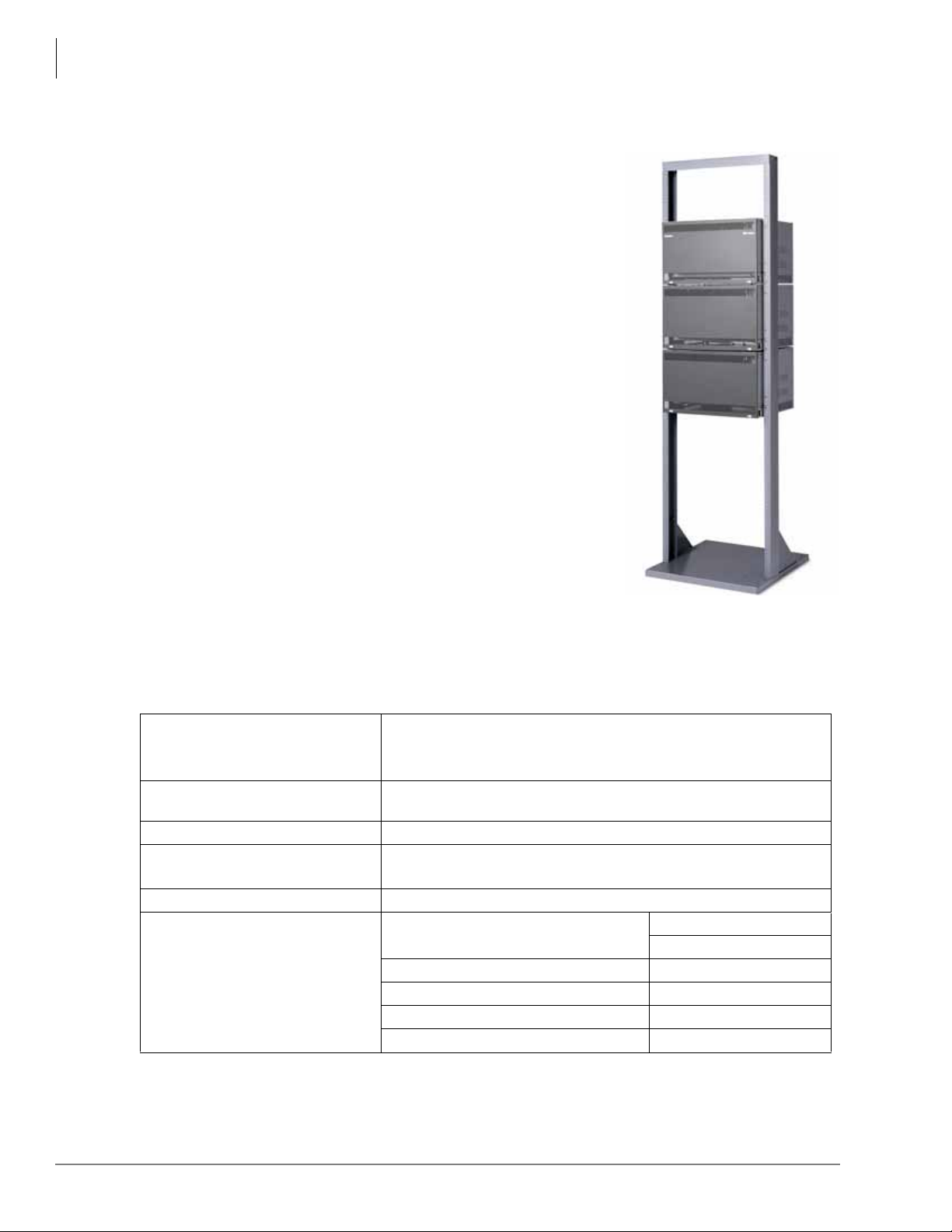
Strata CIX670 and CIX1200
Strata CIX670 and CIX1200 Rack Mount
Strata CIX670 and CIX1200 Rack Mount
The Strata CIX670 and CIX1200 Rack Mount cabinets consist of
a Base cabinet (CRSUB672A) and Expansion cabinets
(CRSUE672A). These cabinets are deeper, narrower, and
designed specifically to fit standard (customer-supplied) 19 ”
racks (shown right). The cabinets are made of plated sheet metal,
dark gray in color with black cover plates. These cabinets support
the same features as the floor/wall-mountable CIX670 and
CIX1200 cabinets.
A CIX670 system can expand from one to seven cabinets using
the same processors and interface cards as the CIX670 floor/wallmountable cabinets. The CIX1200 system can expand from one
to twelve cabinets using the same processors and interface cards
as the CIX1200 floor/wall-mountable cabinets.The power factors
and slot configuration rules are also the same as the floor/wallmountable cabinets.
The difference between the floor/wall mount and the rack mount
cabinets is the size for the Base and Expansion cabinets, the
power supply that is installed in the cabinets, and a unique power
strip for rack mount cabinets (BRPSB120A and the 240V
version).
Toshiba does not support mixing the floor/wall-mountable
cabinets with the rack mountable cabinets. The 19 inch-wide rack
and rack screws must be supplied by the dealer. Interface cables
plug into the front of the station and trunk cards and fold under each cabinet to exit the rear of the
cabinets.
Basic Specifications
The following table lists the parts and basic specifications of the CIX1200 Rack Mount Cabinets.
Dimensions of Base (CSRUB672A)
and Expansion (CSRUE672A)
Cabinet
Weight of Base and Expansion
Cabinet
Power Supply Unit (PSU) BRPSU672A (initially built in) – can also be ordered for spares
19" Rack Installation Dimension IEC297-1 (EIA RS 310-D)
Installation Cannot be floor or wall mounted.
Optional Equipment Power Strip Box
Reserve Power Battery Distribution Box
From PSU to Battery Cable PBTC1A-3M
From BBDB to Battery Cable BBTC1A-2.0M
AC240V Power Supply Cord BACL240A
Height: 6U or 10.5 inches (267mm)
Width: 1.58 feet (483mm—with bracket)
Depth: 1.17 feet (358mm)
22.04 lbs. (10 kg)
465.1mm (front face screw pitch – width)
1
2
BRPSB120A
BRPSB240A
BBDB1A
1. Power strip boxes for floor/wall-mountable cabinets cannot be used for Rack Mount cabinets.
2. Reserve batteries are connected using the same battery distribution box and battery cables as the CIX670
and CIX1200 floor/wall-mountable cabinets.
32 Strata CIX General Description 04/13
Page 55
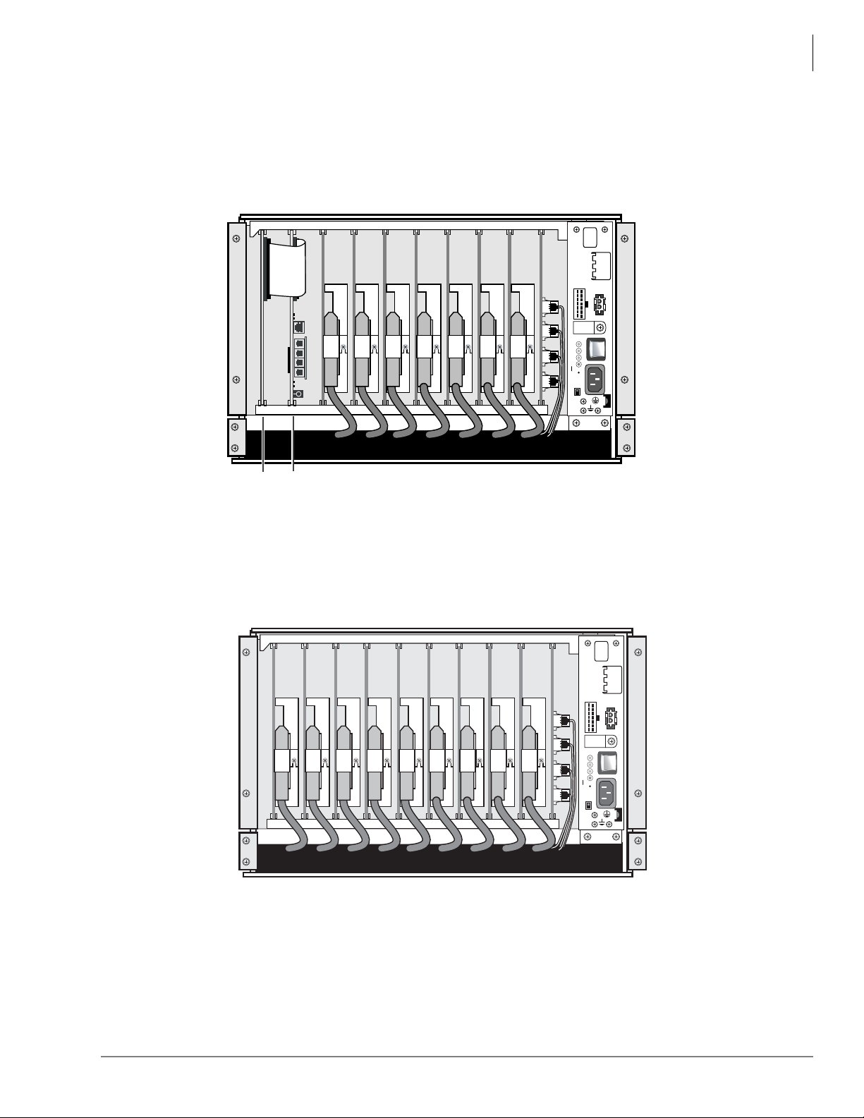
Strata CIX670 and CIX1200
B101 B102 S101 S102 S103 S104 S105 S106 S107 S108
7163
xEXU
xCTU
BATT
EXP
BASE
POW
+5V
-5V
P.F.
RESET
POWER ON
OFF
-24V1
-24V2
-24V3
-24V4
AC IN
DC OUT
+
-
Strata CIX670 and CIX1200 Rack Mount
Base Cabinet
The CIX670 and CIX1200 rack mount base cabinet is similar to the Strata CIX670 and CIX1200
wall mount base cabinet. It has two dedicated slots used for the system processor cards and eight
universal slots, labeled “S101~S108,” that can accommodate station, CO line or option circuit
cards. It also houses a power supply. See Figure 9.
Figure 9 Strata CIX670 and CIX1200 Rackmount B as e Ca bin e t Inte r ior
Expansion cabinet
Each expansion cabinet provides 10 slots (S_01~S_10). Figure 10 shows an Expansion Cabinet.
-24V1
-24V2
-24V3
-24V4
DC OUT
BATT
+
POWER ON
OFF
POW
+5V
-5V
P.F.
RESET
AC IN
EXP
S_01 S_02 S_03 S_04 S_05 S_06 S_07 S_08 S_09 S_10
Figure 10 Strata CIX670 and CIX1200 Rackmount Exp a ns io n Cab in et In teri or
BASE
7164
Strata CIX General Description 04/13 33
Page 56

Strata CIX670 and CIX1200
CIX670 and CIX1200 Remote Expansion Cabinet
CIX670 and CIX1200 Remote Expansion Cabinet
A CIX670 and CIX1200 Expansion Cabinet can be located between a few inches and up to three
kilometers (1.86 miles) from its Base Cabinet. Remote Expansion Cabinets are enabled by the
fiber optic RRCU interface cards. One RRCU connects to up to two Data Cables and applies the
inter-cabinet signal to a multi-mode fiber-optic pair. One fiber pair can support one or two
Expansion Cabinets in one remote location using one RRCU in the Base Cabinet and another in
one of the Remote Expansion Cabinets.
CIX1200 expansion cabinets 8 through 12 must be connected as remote cabinets using RRCU
interface cards and multi-fiber optic cables.
Fiber connected cabinets support the BIOU for external Page Zones, Night Bell, etc., and all CO
line and trunk interface circuit cards. Network clock synchronization can only be derived from
digital trunks installed in the Base Cabinet or a expansion cabinet connected with standard ribbon
cables, not fiber cables.
A Remote Cabinet can support all circuit cards that can be installed in a local Expansion Cabinet,
including digital trunk cards. However, the system cannot derive network clock synchronization
from a digital trunk installed in a Remote Cabinet. This requires a digital trunk installed in the
Base Cabinet or in a local Expansion Cabinet connected to the Base by a standard ribbon cable.
For each Remote Cabinet location, local trunks may be required for correct 911 service.
34 Strata CIX General Description 04/13
Page 57

Universal Slot Circuit Cards 6
Universal Printed Circuit Cards installed in the Strata CIX1200, CIX670, CIX200 or CIX100
cabinets provide interfaces for stations, lines, and peripherals. Each circuit card measures 7.5 x 5.5
inches (190 x 140 mm) and mounts in the slot with a 44-pin backplane connector. Circuit Card
external connections to station equipment are made to the Main Distribution Frame (MDF) using
industry-standard connectors.
Important! This chapter does not apply to the Strata CIX40, except for GVPH, GIPU8, MIPU16
and MIPU24.
Station, Line and Option Circuit Cards
The Circuit Cards are categorized as station, CO line or option cards (see Tables 11~13). Feature
subassemblies that plug onto a universal slot circuit card are listed below the associated card. For
details, see the Strata CIX I&M Manual.
T able 11 Station circuit cards
Internet Protocol Telephone (IPT) Interface Unit (MIPU, LIPU/LIPS, GIPU and GIPH)
Provides IPT telephone circuits (IP5000-series,
IPT2010-SD, IPT2020-SD and IPT2008-SDL)
1 100Base-TX RJ45 port
Built-in Digital Signal Processor (DSP)
1 RS-232 maintenance port
Network Address Translation (NAT) compatible for
remote IP telephones when connected to a MIPU /
LIPU.
Enhanced version of MEGACO+ for Voice over IP
Supports SIP telephones and UIP200
Simultaneously supports Line interfaces.
Digital Telephone Interface Unit (ADKU, BDKU/BDKS, BWDKU1A)
Provides digital telephone circuits for DP5000series, DKT3000/3200-series digital telephones.
Stand-al one digital cordless telephone
DDM5060 console
DDSS3260 console
DDCB – Door Phone
Stand-al one digital cordless telephone
DDM console
BATI – Digital Attendant Console
MIPU16 – supports 16 IP channels (supported by CIX40 R1 and
R2 cabinets)
MIPU24 – supports 24 IP channels (supported by CIX40 R2
cabinet)
LIPU-X1A – supports 16 IP channels
LIPS-X1A – supports 16 IP channels and mounts on LIPU
LIPU/LIPS is not supported by CIX40
GIPU8, GIPH-X1A – supports 8 IP channels for CIX40 only
Interface Options: LAN, Virtual Private Network (VPN) Internet,
VPN WAN, Intranet.
ADKU = 8 circuits (CIX100 only)
BDKU = 8 circuits
BDKS = 8 circuits
BWDKU = 8 circuits
Strata CIX General Description 04/13 35
Page 58

Universal Slot Circuit Cards
Station, Line and Option Circuit Cards
T able 11 Station circuit cards (continued)
Standard Telephone Interface Unit (LSLU - CIX200 only) (ASTU - CIX100 only)
Provides two standard telephone circuits.
Maximum number of ringers per circuit is one.
Standard Telephone Interface Unit (Card Slot Mount) (BSLU/BSLS - All CIX Systems)
Provides eight (BSLU) or 16 (BSLU + BSLS)
standard telephone circuits. Maximum number of
ringers per circuit is one
Standard Telephone Interface Unit with Caller ID (Card Slot Mount) (BSTCIU - All CIX Systems, except CIX40)
Provides eight standard telephone circuits with
Caller ID. Maximum number of ringers per circuit is
three. The BSTCIU2A offers disconnect
supervision.
Standard Telephone Interface Unit (BSTU)
Provides 8 standard telephone circuits. Stutter dial
tone is provided for Message Waiting audible
indication. The BSTU2A offers disconnect
supervision.
-48 Volt Supply Internal Option (R48S)
Attaches to BSTU and BSTCIU
48VDC circuit for up to 8 standard telephone
circuits.
Not available on LSLU, BSLU/BSLS, ASTU
Voice Mail
GVPH (CIX40 only)
L VMU1A (CIX100, CIX200, CIX670, and CIX1200)
Interface Options:
Standard telephones (no message waiting lamp control - no OPS
(48V))
Other single-line devices
Alternate MOH/BGM source
Fax machines
Voice mail devices
Interface Options:
Standard telephones (no message waiting lamp control)
Other single-line devices
Alternate MOH/BGM source
Fax machines
Voice mail devices
No 48 Volt Off-premises Station support
Interface Options:
Standard telephones with Caller ID displays
Message Waiting Lamp Control
Off Premise Station (OPS)
VM devices
MOH / BGM
Interface Options:
Standard telephones
Voice mail ports
Off-premises stations
Other similar devices
Alternate MOH/BGM source
Auto Attendant digital announcer
Message Waiting Lamp Control
Fax machines
ACD announcer
Interface Options: Optionally interfaces to the BSTU and
BSTCIU to extend loop length of standard telephones from 600
ohms to 1200 ohms. Required for OPS operation.
Pre-programmed Voicemail Auto attendant circuit card.
4 Voice mail / Auto attendant ports default; 6 and 8 ports require
LIC-2 GVPH
40 hours storage – 360 mail boxes
Call record, Voice mail Call monitor and built-in modem
Pre-programmed Voicemail Auto attendant circuit card.
8 Voice mail / Auto attendant ports
40 hours storage – 360 mail boxes
Call record, Voice mail Call monitor and built-in modem
36 Strata CIX General Description 04/13
Page 59
T able 11 Station circuit cards (continued)
Preprogrammed for plug-and-play in CIX Base or Exp., provides
Stratagy iES32 (CIX100, CIX200, CIX670, and
CIX1200)
4~32 voice ports. Also supports fax server and Unified
Messaging (UM). 10/100BaseT Ethernet connection and a serial
port used for Toshiba Proprietary Integration (TPI). (See Stratagy
General Description for details).
The Stratagy iES16 is an integrated voice mail system that can
be installed in a card slot inside a Strata CIX system.
The Stratagy iES16 supports a maximum of 16 voice ports, and
Stratagy iES16 (CIX100, CIX200, CIX670, and
CIX1200)
is available in model increments of 4 ports (4, 8, 12, 16 ports).
The Stratagy iES16 also ships with Unified Messaging and 5
client seats standard, and can be configured for all of the
advanced applications of the iES32, specifically up to 4 channels
of fax and 8 channels of Te xt to Speech.
Table 12 CO Line Circuit Cards
Strata Net Over VoIP Interface Unit (MIPU, LIPU/LIPS, GIPU and GIPH)
MIPU16 – supports 16 IP channels
Provides 32 IP Strata Net channels
1 100Base-TX RJ45 port
1 RS-232 maintenance port
Based on IP Strata Net standard protocol (ECMA-336)
Voice coding G.711/G.729A
Built-in Digital Signal Processor (DSP)
Simultaneously supports IPT Station interfaces
MIPU24 – supports 24 IP channels
LIPU-X1A – supports 16 IP channels
LIPS-X1A – supports 16 IP channels and mounts on
LIPU
LIPU/LIPS is not supported by CIX40
GIPU8, GIPH-X1A – supports 8 IP channels for CIX40
only
Interface Options: LAN, Virtual Private Network (VPN)
Internet, VPN WAN, Intranet.
SIP Trunking (MIPU)
Provides 24 IP Strata Net channels
1 100Base-TX RJ45 port
1 RS-232 maintenance port
Voice coding G.711/G.729A
GIPU8 – supports 8 IP channels
MIPU16 – supports 16 IP channels
MIPU24 – supports 24 IP channels
Built-in Digital Signal Processor (DSP)
Simultaneously supports IPT Station interfaces
Internet Protocol (IP) Interface Unit (BVPU)
Provides 4 VoIP Circuits as E&M Tie lines
1 10Base-T port
1 RS-232 maintenance port
Interface Options: LAN, Internet, WAN.
H.323 standard for Voice over Internet Protocol (VoIP)
Caller ID Interface Unit (RCIU2 / RCIS)
Interface Options:
Provides 4 Caller ID circuits.
With RCIS: 8 circuits.
Provides Caller ID LCD display for analog loop or ground
start lines with Caller ID. Requires: RCOU, RCOS,
RGLU2, RGLU3 or PCOU. Not compatible with T1.
Caller ID Interface Subassembly (RCIS)
Attaches to the RCIU2.
Same as RCIU2.
Direct Inward Dialing Interface Unit (RDDU)
Provides 4 DID circuits.
Interface Options:
DID analog lines.
Enhanced 911 CAMA Trunk Interface Unit (RMCU/RCMS)
E911 CAMA circuits. Provides up to 4 CAMA trunk circuits.
The RMCU/RCMS eliminates the need for connection of
adjunct terminal adapter equipment to E911 CAMA trunks.
E911 analog CAMA trunks.
Requires 1 or 2 RCMS circuit cards for 2 or 4 CAMA lines
respectively.
Universal Slot Circuit Cards
Station, Line and Option Circuit Cards
Strata CIX General Description 04/13 37
Page 60
Universal Slot Circuit Cards
Station, Line and Option Circuit Cards
Table 12 CO Line Circuit Cards (continued)
CAMA Trunk Subassembly (RCMS)
RCMS attaches to RMCU. Provides 2 E911 CAMA circuits.
Up to 2 RCMSs per RMCU for 4 CAMA lines max. (1 RCMS
comes packaged with the RMCU.)
Ground/Loop Start Interface CO Line Interface Unit (RGLU3)
Provides 4 ground or loop start line circuits. Each can be
individually set for ground or loop start operation.
ISDN Primary Rate Interface Unit (RPTU and BPTU)
Provides (1~8B + D), (1~16B + D), or (1~23B + D) channels
(lines), depends on system programming.
RPTU2 is required for Strata Net Networking.
Loop Start CO Line Interface Unit (RCOU3A and RCOS3A)
Provides 4 CO analog loop start line circuits.
With RCOS, provides 8 CO analog loop start line circuits.
Loop Start CO Line Interface Subassembly (RCOS)
Provides 4 additional Loop Start CO lines. 1 RCOS
subassembly per RCOU.
Loop Start CO Line Interface with Caller ID Unit (BCOCIU1A)
Provides four CO analog loop start line circuits.
With BCOCIS1A, provides eight CO analog loop start line
circuits. Caller ID interface is built-in, RCIU is not needed.
Loop Start CO Line Interface Subassembly (BCOCIS1A)
Provides 4 additional Loop Start CO lines with built-in Caller
ID interface. Mounts on the BCOCIU1A.
T1/DS-1 Interface Unit (RDTU)
Provides T1 (DS1) Interface: 1~8, 1~16, or 1~24 channels
(lines), depends on system programming.
Remote Expansion Cabinet Unit (RRCU)
Supports 2 CIX670 and CIX1200 remote cabinets. 62.5 mμ,
multi-mode fiber.
Tie Line Unit (REMU2)
Provides 4 analog Tie line circuits.
Same as RMCU.
Interface Options:
Analog loop or ground start analog lines.
Interface Options:
ISDN PRI
POTS
FX
Tie (senderized)
Tie (cut through)
OUTWATS (intra-LATA) and (inter-LATA)
InWATS
Strata Net
Interface Options:
CO analog loop start lines
Same as RCOU.
RCOU/RCOS requires RCIU2/RCIS to support Caller ID.
Interface Options:
CO analog loop start lines (Does not support Type 2
Hook-Flash to answer a waiting call, does not provide
dial pluse output)
Same as BCOCIU1A.
Interface Options:
T1
Loop start lines
Ground start lines
Tie lines (wink or immediate)
DID/DOD lines (wink or immediate)
Remote Cabinet not supported by main system reserve
power.
Interface Options:
E&M Tie lines
2- or 4-wire transmission
Type I and type II signaling
Immediate start
Wink start
38 Strata CIX General Description 04/13
Page 61

Universal Slot Circuit Cards
Station, Line and Option Circuit Cards
Table 13 Option Circuit Cards
Option Interface Unit (BIOU)
Option Interface Unit (BSIS) Interface Options: Provides four RS232 ports.
Interface Options: Provides Paging output (600 ohm and
3-watt amp), 4 zone paging relays, three MOH interfaces
and 4 control relays (Night Transfer and BGM mute).
Strata CIX General Description 04/13 39
Page 62
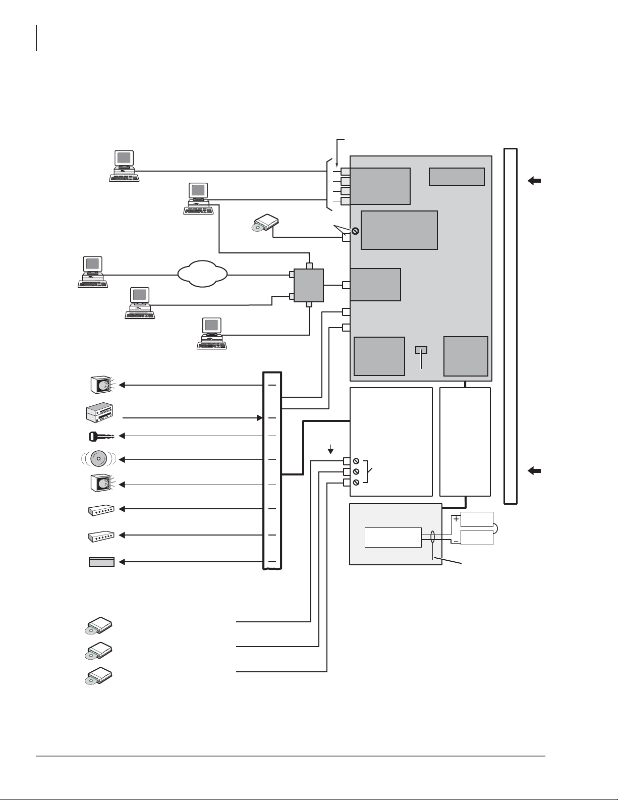
Universal Slot Circuit Cards
Data and Speech Highway
0014-cix40
ACTU3A
Processor PCB
(one or two per system)
Relay Contacts
Virtual slot 09
ASTU
MOH/BGM
RCA Jacks
Battery Charger
ABCS
12V
Battery
12V
Battery
(2 or 4 Batteries)
Page output
Relay Contact
ABTC - 3m Cable
MOH/BGM Jack
+Volume Control
APSU112
Cabinet
Power Supply
MOH/BGM
Volume Controls
RCA Jack
Screw Connection
Up to Four Programmable Serial (RS-232)
Port Modular Jacks Available
ACD
(CSTA)
SMDR
Call Accounting
Remote CIX
eManager PC
Local CIX
eManager
Notes
1. Optional.
2. License Control.
Music Source 1: Background Music
and/or Music-on-hold
Music Source 2: Background Music
and/or Music-on-hold
Music Source 3: Background Music
and/or Music-on-hold
BSIS
2
(Optional)
Conference
SW with PAD
Interface PCB
BIOU
1
1
1
AMDS
Remote Maintenance
Modem
1
1
Ethernet
Interface
DTMF/ABR
Receivers
RJ45
Smart Media
Maintenance
and
Customer
Database
License
Internet
Music Source: External Zone Page
Background Music
Door Lock Control Relay
External Zone Page Relays (4 Zones)
External Page Amplifier (600 ohm Output)
Main Distribution
Frame (MDF)
Night Bell Control Relay
Amplified Page Output (3 Watts)
BGM Mute Control Relay
Night Control Relay
Hub
or
LAN
SMDI or Toshiba Proprietary
Integration
Toshiba Proprietary Soft Key LCD Link
Stratagy ES
Voice Mail
On this page, all equipment, except Stratagy ES,
connected to the system processor PCBs and
BIOU PCB is customer-supplied.
Functional Block Diagrams
Functional Block Diagrams
The Functional Block Diagrams show the circuit cards and interface connectors used for
connecting the stations and peripherals (see Figures 11~15).
Figure 11 CIX100 System Processor and Optional Interface Circuit Cards
40 Strata CIX General Description 04/13
Page 63
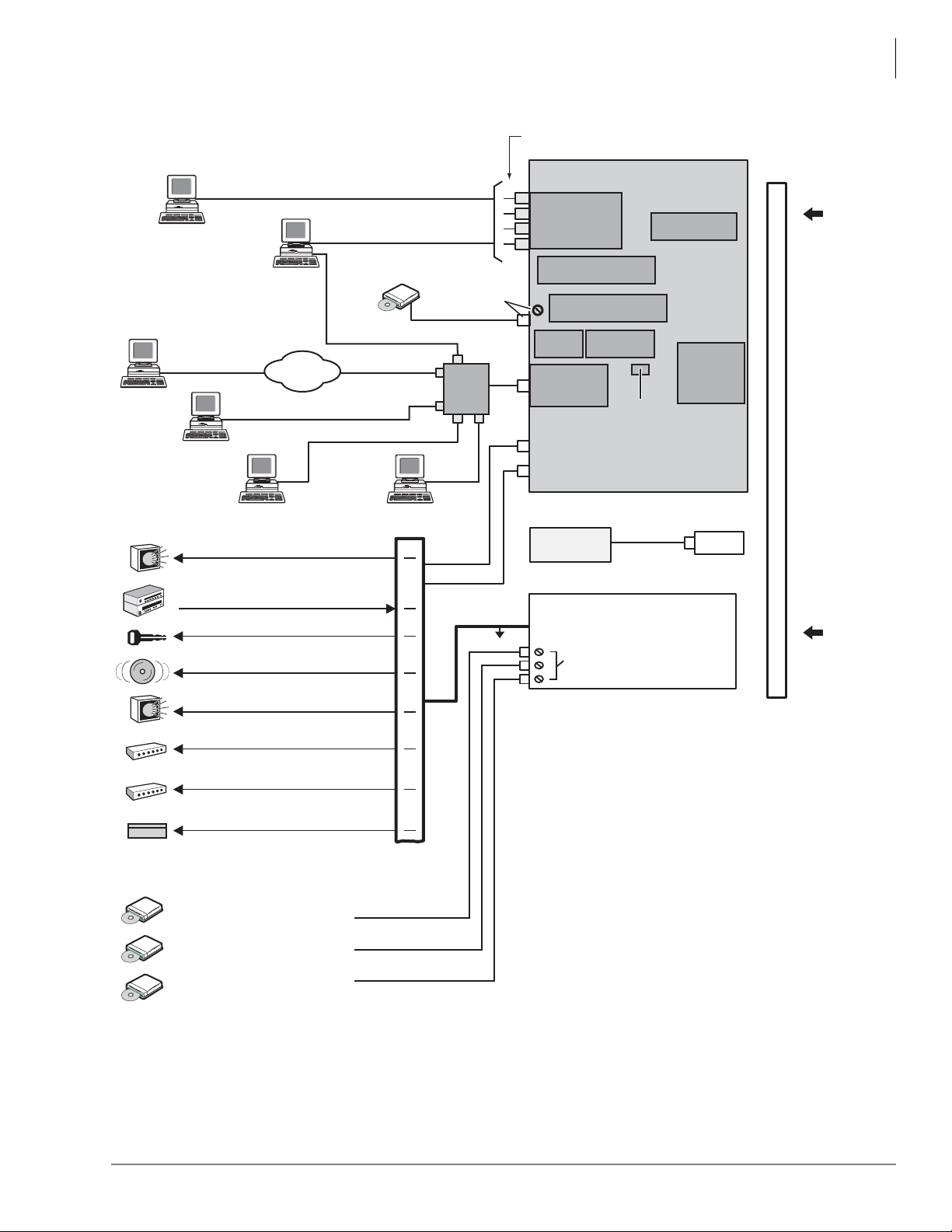
Data and Speech Highway
0017-cix40
LCTU2A
Processor PCB
Interface PCB
Relay Contacts, Page Output
Music Source: External Zone Page
Background Music
Door Lock Control Relay
External Zone Page Relays (4 Zones)
External Page Amplifier (600 ohm Output)
Main Distribution
Frame (MDF)
Night Bell Control Relay
MOH/BGM Jack
+Volume Control
MOH/BGM
Volume Controls
Up to Four Programmable Serial (RS-232)
Port Modular Jacks Available
ACD
(CSTA)
SMDR
Call Accounting
Amplified Page Output (3 Watts)
Remote CIX
eManager PC
Local CIX
eManager
BGM Mute Control Relay
Night Control Relay
Notes
1. Optional.
2. Optional. See description of License Control
earlier in this chapter.
3. Optional one or two per system.
Music Source 1: Background Music
and/or Music-on-hold
Music Source 2: Background Music
and/or Music-on-hold
Music Source 3: Background Music
and/or Music-on-hold
2
AMDS1 Remote
Maintenance Modem
BSIS
(Optional)
Conference
SW with PAD
Ethernet
Interface
DTMF/ABR
Receivers( Built-In )
BIOU
3
RJ45
Secure Digital
Maintenance
and
Customer
Database
License
Internet
MOH/BGM
RCA Jacks
Hub
or
LAN
SMDI and Stratagy ES Integration
Toshiba Proprietary Soft Key LCD Link
Stratagy ES
Voice Mail
On this page, all equipment, except Stratagy ES,
connected to the system processor PCBs and
BIOU PCB is customer-supplied.
Memory Time Switch
Page output
Relay Contact
RCA Jack
Screw Connection
110 V
AC only
Cabinet
Power Supply
IP Attendant Console
Universal Slot Circuit Cards
Functional Block Diagrams
Figure 12 CIX200 System Processor and Optional Interface Circuit Cards
Strata CIX General Description 04/13 41
Page 64
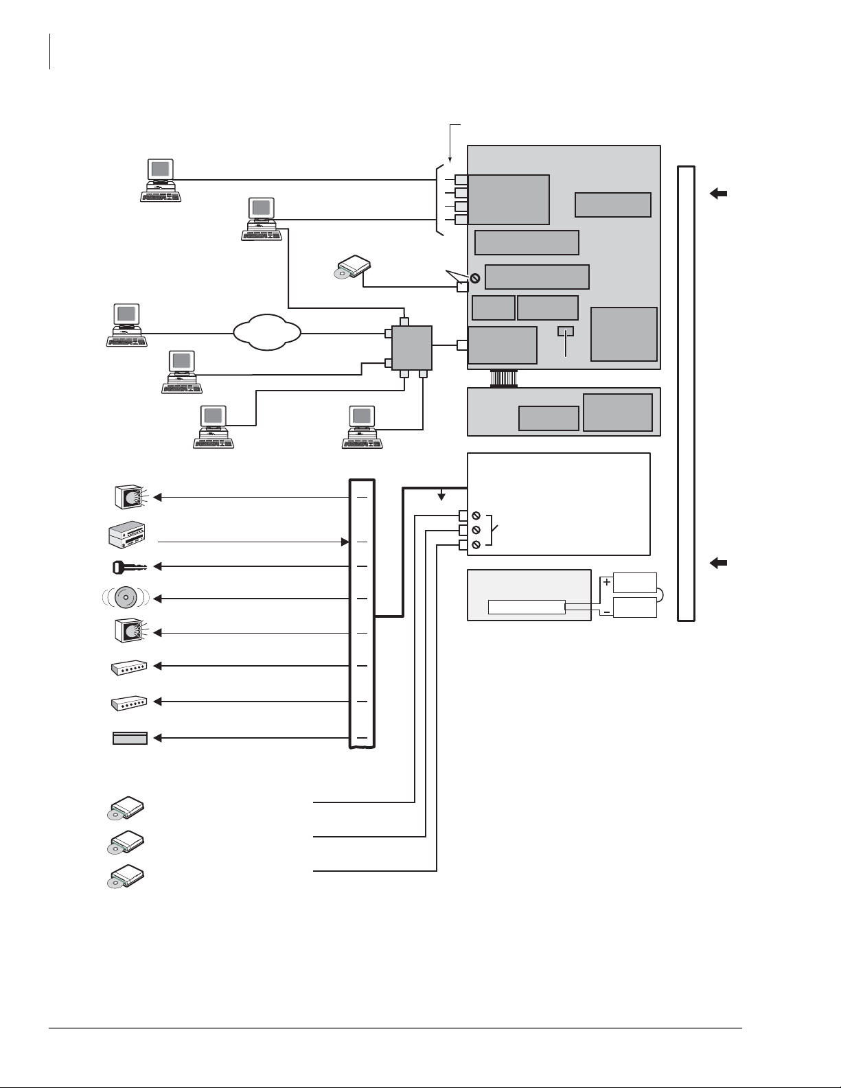
Universal Slot Circuit Cards
Data and Speech Highway
0013-cix40a
xCTU
Processor PCB
Interface PCB
Relay Contacts, Page Output
Music Source: External Zone Page
Background Music
Door Lock Control Relay
External Zone Page Relays (4 Zones)
External Page Amplifier (600 ohm Output)
Main Distribution
Frame (MDF)
Night Bell Control Relay
Battery Charger
12V
Battery
12V
Battery
(2 or 4 Batteries)
MOH/BGM Jack
+Volume Control
BPSU672
Cabinet
Power Supply
MOH/BGM
Volume Controls
Up to Four Programmable Serial (RS-232)
Port Modular Jacks Available
ACD
(CSTA)
SMDR
Call Accounting
Amplified Page Output (3 Watts)
Local CIX
Network eManager
IP Attendant Console
BGM Mute Control Relay
Night Control Relay
Notes
1. Optional.
2. Optional. See description of License Control
earlier in this chapter.
3. Optional one or two per system.
Music Source 1: Background Music
and/or Music-on-hold
Music Source 2: Background Music
and/or Music-on-hold
Music Source 3: Background Music
and/or Music-on-hold
2
AMDS1 Remote
Maintenance Modem
BSIS
(Optional)
Conference
SW with PAD
Ethernet
Interface
DTMF/ABR
Receivers( Built-In )
BIOU
3
RJ45
Secure Digital
Maintenance
and
Customer
Database
License
Internet
MOH/BGM
RCA Jacks
xEXU
Processor PCB
Memory
Time Switch
DTMF/ABR
Receivers
( Built-In )
Hub
or
LAN
SMDI and Stratagy ES Integration
Toshiba Proprietary Soft Key LCD Link
Stratagy ES
Voice Mail
On this page, all equipment, except Stratagy ES,
connected to the system processor PCBs and
BIOU PCB is customer-supplied.
Memory Time Switch
Remote CIX
Network eManager PC
Functional Block Diagrams
Figure 13 CIX670 and CIX1200 System Processor and Option Interface Circuit Cards
42 Strata CIX General Description 04/13
Page 65
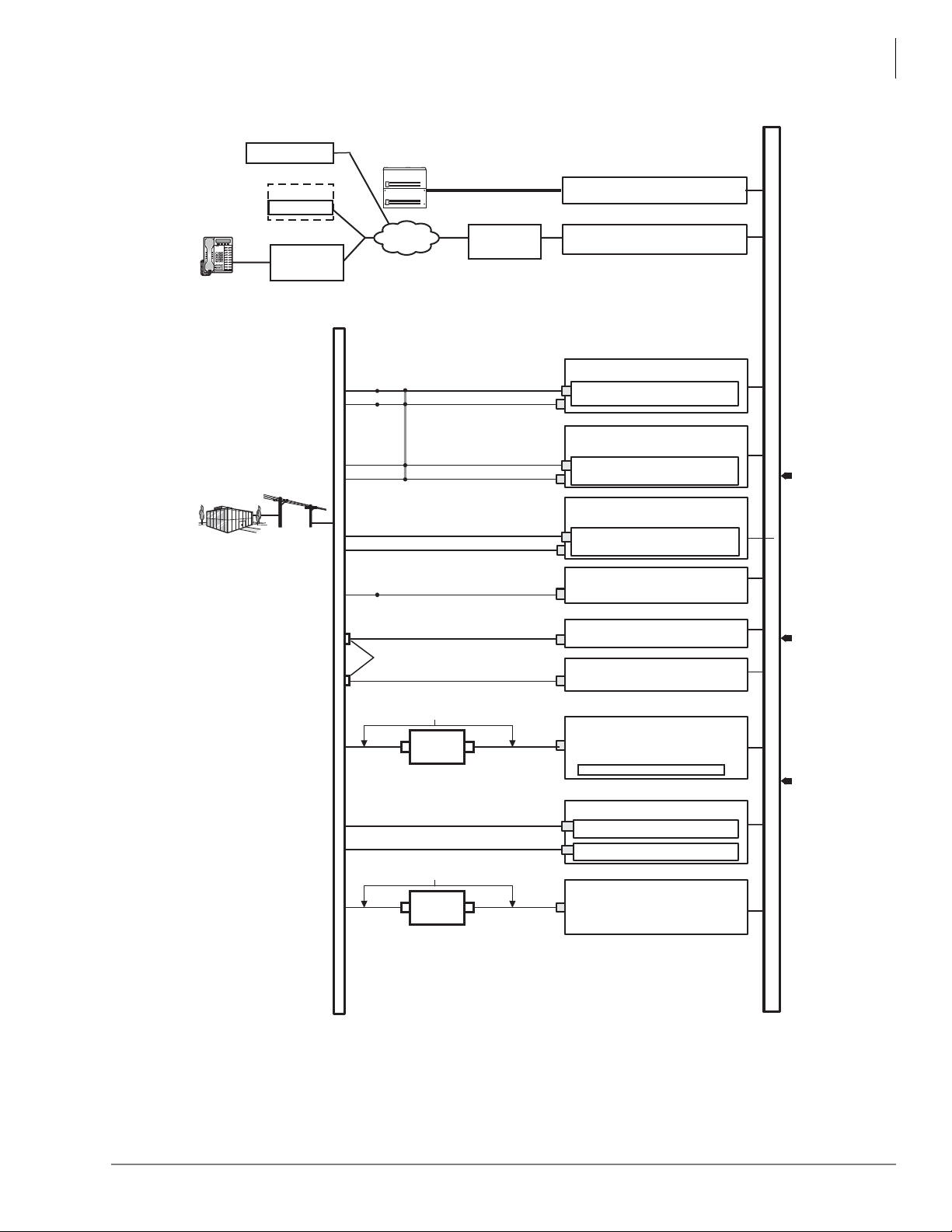
Universal Slot Circuit Cards
RDTU3
• 2T1 / DS1(24 Channels / Lines)
• Loop Start, Ground Start, Tie, DID
• Digital Voice Lines
PLL Synchronization Circuits
RCOU3
4 Loop Start Co Lines (Analog)
RGLU3
4 Loop or Ground Start CO Lines (Analog)
RCOS
(Optional PCB on RCOU Only):
4 Loop Start CO Lines (Analog)
RCIU2
RCIS
4 Caller ID Circuits
4 Caller ID Circuits
(Two 4-Wire Modular Jacks)
MDF
(Two 4-Wire Modular Jacks)
(Two 4-Wire Modular Jacks)
(Two 4-Wire Modular Jacks)
(Two 4-Wire Modular Jacks)
1
RDDU2
4 DID CO Lines (Analog)
REMU2
4 E&M Tie Lines (Analog)
(REMU, Four 8-Wire Modular Jacks)
(Two 4-Wire Modular Jacks)
Secondary Protectors
2
BPTU1
ISDN PRI (23B+1D channels)
Digital Voice/Data
Toshiba RDTU3-CBL-KIT
Channel
Service
Unit (CSU)
8-wire Modular Jacks
2
Toshiba RPRI-CBL-KIT
Channel
Service
Unit (CSU)
8-wire Modular Jacks
2
RMCU
Trunk Circuits for E911
RCMS 2 Trunk Circuits
RCMS 2 Trunk Circuits
CAMA Line (2-wire Modular Jacks)
CAMA Line (2-wire Modular Jacks)
Network
Demarcation
Point
RRCU
Remote Cabinet Interface Card
Optical Fiber Cable
3 km/(1.86 mi.)
CTX670 and CIX1200
Expansion Cabinets
0015-cix40
4
Central Office
Centrex
PBX
Common Carrier
Other Telephone System
E911 Public Safety Answer
Point (PSAP)
Priviate Networking Lines
•
•
•
•
•
•
•
•
•
•
•
•
Data and Speech Highway
QSIG networks (RPTU2)
4
1. RCIU2/RCIS tip/ring cross
connected to RCOU, RCOS, or
RGLU tip/ring at MDF.
2. Customer-supplied equipment.
3. U, S, T, R, are ISDN reference
model termination points.
4. RPTU2 is required for QSIG
Networking.
CiX
MIPU, LIPU/LIPS
Remote Location(s)
Page ScrollMode Feature
Msg
Mic Redial
Spdial
Spkr
Cnf/Trn
Hold
Vol
Remote Location(s)
MIPU, LIPU/LIPS
IP Telephone
With or without
VPN Router
or Server
IP Network
(CIX670 and CIX1200 only)
BCOCIU
4 Loop Lines with Caller ID
BCOCIS
4 Loop Lines with Caller ID
(Two 4-Wire Modular)
(Two 4-Wire Modular)
With or without
VPN Router
or Server
SIP Trunk Provider
CIX Network
Functional Block Diagrams
Figure 14 CIX100, CIX200, CIX670, and CIX1200 CO Line Side Functional Block Diagra m
Strata CIX General Description 04/13 43
Page 66
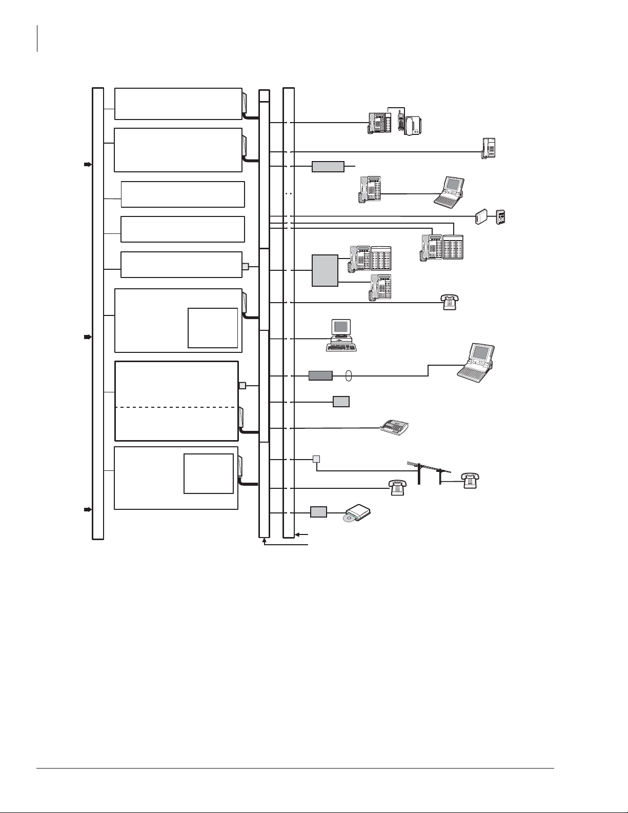
Universal Slot Circuit Cards
1
1
1
1
2
BSTCIU
BDKU
8 Digital Telephone Circuits and
BDKU/BDKS
16 Digital Telephone Circuits
R48S
(Option PCB)
-48 Volt
Loop Supply
R48S
(Option PCB)
-48 Volt
Loop Supply
Digital Telephone (DP)
and Add-on Module
Digital Telephone
3
DDCB
Cordless DKT
MDFB
Door Phones and
Lock Controls
TAPI PC
1 Pair Modular Cord
RS-232 Cable
PC
1-pair Modular Cords
Modem
RS-232 Cables
Connects audio path to Attd Console
Handset
3
Modular Jacks
Main Distribution Frame (MDF)
Off-premises Station (BSTU only)
Secondary
Protector
1. Customer-supplied equipment.
2. RSTU2 or above is required for standard telephone message
waiting lamp.
3. PDKU and RDSU should only be used for 2000-series digital
telephones. They do not support all of the 3000-series and 5000-series
digital telephone features, including LCD. The PDKU also does not
support BPCI, BATI and the CTX Attendant Console.
Fax
0016-cix40d
BSTU
8 Standard
Telephone Circuits
Digital Single Line
Telephone (DP)
Standard
Telephone
(with caller ID)
Standard
Telephone
BWDKU
8 or 16 Digital Telephone Circuits
Music
on-hold
source
(up to 8)
iES32
4~32 Voice Mail Circuits (Programmable)
IVP8
2~8 Voice Mail Circuits (Programmable)
MIPU/LIPU/LIPS
Data and Speech Highway
2 Standard Telephone Circuits
ASTU (CIX100)
LSLU (CIX200)
BSLU/BSLS All CIX
16 Standard
Telephone Circuits
8 Standard
Telephone Circuits
with Caller ID
BATI
Transformer
Auto Attendant
(Dealer supplied)
Stratagy ES
Voice Mail
VM Ports
LAN
Digital Telephone
with DSS Console
Page ScrollMode Feature
Msg
Mic Redial
Spdial
Spkr
Cnf/Trn
Hold
Vol
IP Telephone
with DSS Console
IP Telephone
Page ScrollMode Feature
Msg
Mic Redial
Spdial
Spkr
Cnf/Trn
Hold
Vol
Page ScrollMode Feature
Msg
Mic Redial
Spdial
Spkr
Cnf/Trn
Hold
Vol
Page ScrollMode Feature
Msg
Mic Redial
Spdial
Spkr
Cnf/Trn
Hold
Vol
Page ScrollMode Feature
Msg
Mic Redial
Spdial
Spkr
Cnf/Trn
Hold
Vol
Functional Block Diagrams
Figure 15 Strata CIX100, CIX200, CIX670, and CIX1200 Station Side Functional Block Diagram
44 Strata CIX General Description 04/13
Page 67

Telephones and Peripherals 7
This chapter covers Toshiba’s 5000-series Digital Telephones (DP), Internet Protocol Telephones
(IP) and peripherals that are compatible with Strata CIX telephone systems.
DP5000-series Digital Telephones
The DP5000-series telephones replace the DKT3200-series telephones in the Toshiba product line.
All three generations of telephones, DKT2000, DKT3200 and DP5000, can co-exist with full
functionality in one Strata CIX system with Release 5.1 software or above.
Although the DP5000-series telephones can be used on a CTX28 they will have limited
functionality.
The DP5000 telephones have three operational modes:
• When connected to Strata CIX systems with Release 5.1 or above, they will automatically run
in DP5000 Mode.
• When connected to Strata CIX systems with older than Release 5.1 (including Release 3) the
DP5000-series telephones will automatically act as DKT3200 telephones; DP5000-series
telephones can also be programmed to act as DKT2000 telephones.
• When connected to a PDKU card DP5000-series telephones automatically act as DKT2000
telephones.
• The DP5000 Backlight feature will function on all Strata CIX systems, regardless of the system
software version.
Strata CIX General Description 04/13 45
Page 68
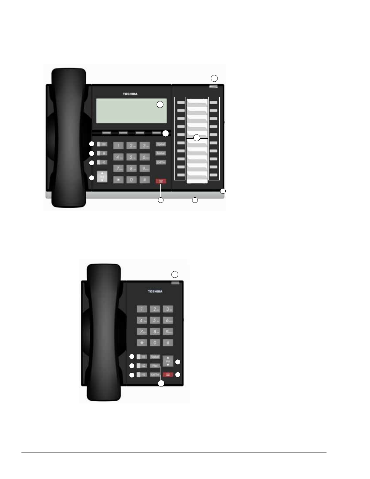
Telephones and Peripherals
20 Programmable Feature Buttons 4-Line LCD Telephone
A
B
C
E
F
G
H
I
J
K
D
Single Line Telephone 1 Programmable Button
A
D
H
I
E
L
G
DP5000-series Digital Telephones
DP5000-series Telephone Illustrations
Legend
A. Status LED (message and ringing)
B. LCD Display
C. Softkeys
D. Programmable Feature Buttons
E. Message Waiting LED Button
F. Microphone LED Button
G. Speaker LED Button
H. Volume
I. Hold Button
J. Microphone
K. Tilt stand
L. Off-Hook Button (Single Line
Telephone)
46 Strata CIX General Description 04/13
Page 69
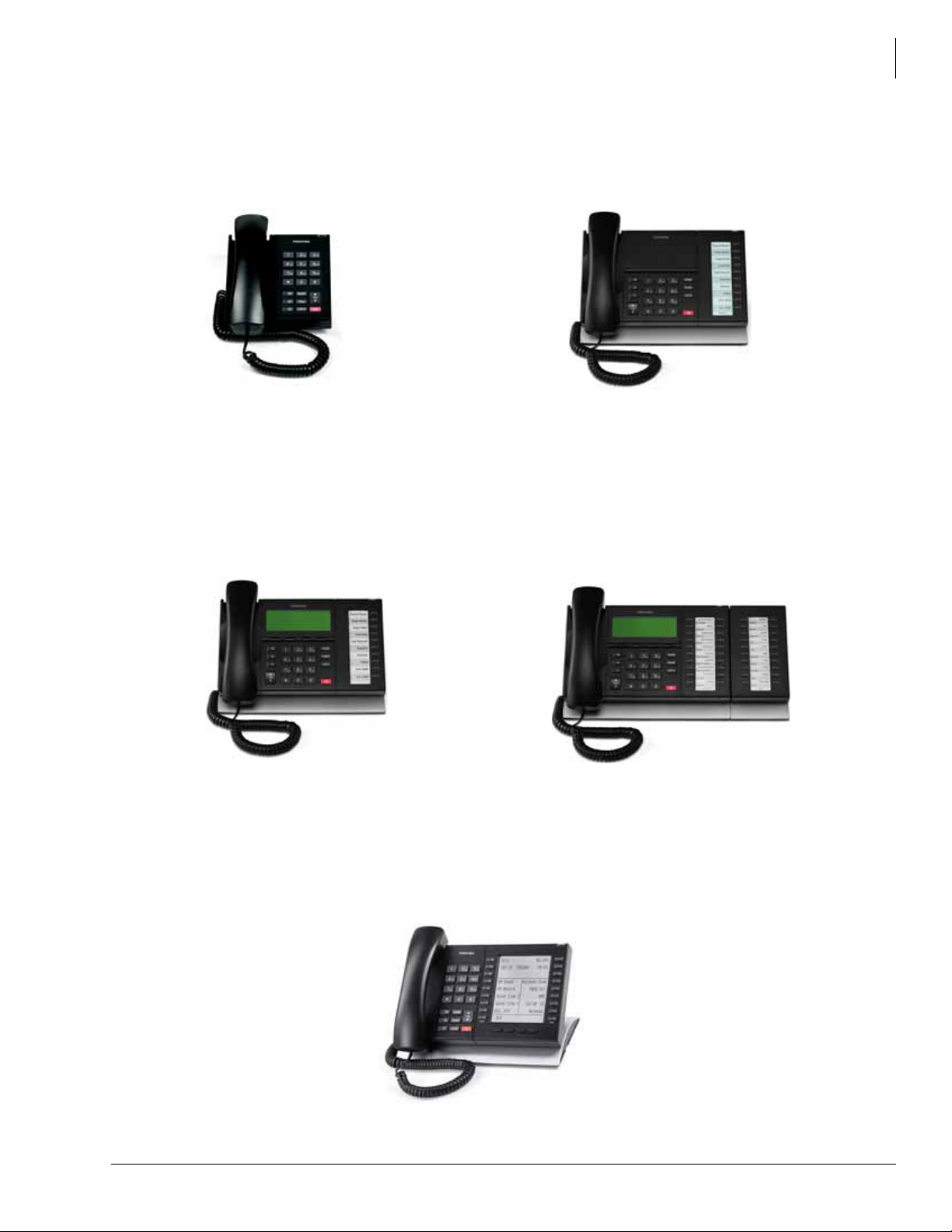
Telephones and Peripherals
DP5130-SDL and DP5130-FSDL
Digital half duplex and full duplex speakerphone
options with 20 programmable buttons, 9-line
LCD display with backlight.
DP5000-series Digital Telephones
DP5008
Digital Single Line Telephone
DP5022-SDM (CIX40 only)
DP5022-SD
DP5122-SD
Digital Speakerphone with 10 programmable
buttons 4-line LCD display
DP5018-S
Digital Speakerphone with 10
programmable buttons
DP5032-SD
DP5132-SD
Digital Speakerphone with 20
programmable buttons, 4-line LCD
display with backlight option (shown
with KM5020)
Strata CIX General Description 04/13 47
Page 70

Telephones and Peripherals
DP5000-series Digital Telephones
The DP5000 Look
• Sleek low profile — less than 1-inch thick.
• Black body with dark gray keys.
• Metallic silver curved tilt stand with eight adjustable positions.
Large Display Area for Call Information
• New LCD Technology — High Contrast LCD panel.
• All LCDs are 24 characters wide.
• Four lines of LCD to display call information (on the DP5022-SDM, DP5022-SD, DP5122-SD,
DP5032-SD, and DP5132-SD telephones).
• Nine lines of LCD on the DP5130-SDL and DP5130-FSDL telephones.
• Advisory Messages.
• Automatic Number Identification (ANI).
• Caller ID, Name and Number with call history.
• Contrast adjustment (13 levels).
•Date/Time of Day.
• Dialed Number Identification Service (DNIS Name and Number).
• Feature Prompting Soft Keys that are used as an alternative to access codes or feature buttons.
Station users can access features by responding to LCD prompts.
• Called Number displays on outgoing calls (1~120 seconds).
LCD Key-Strip
• Integrated in the DP5130-SDL and DP5130-FSDL telephones.
• Integrated in the LM5110 ad d-on module. This module is supported on all of the DP5000 series
telephones except the DP5008.
• Key labels are programmable via eManager, MyPhone Manager (both local and remote), or
user programming mode.
• User programmable line and trunk labels.
• Feature labels – user selectable.
• Ease of deployment and dynamic changes.
Backlight LCD
• Available on: DP5122-SD, DP5132-SD, DP5130-SDL, DP5130-FSDL, and LM5110.
• Place the telephones anywhere: regular office, reception area, high-end home studio, hotel
lounge, low-light environments, etc.
• LCD backlight can be set to always on, always off or synchronized which turns backlight on
anytime activity is sensed on the telephone and will automatically shut off after a period of time
to conserve energy.
48 Strata CIX General Description 04/13
Page 71

Telephones and Peripherals
DP5000-series Digital Telephones
Mic Mute
Note Not supported on DP5008.
• All models have microphone and half duplex speaker capability.
• Enhanced Mute – the handset and microphone are muted simultaneously.
• The MIC key on the telephones toggles between Mic and Mute. When Mic key is lit, hands free
communication is supported, when the Mic key is pressed and light is off, Mute is enabled.
Handset/Headset
• Built-In Headset Interface.
• Built-in Carbon Handset Interface controlled by software.
• Speaker Off-hook Call Announce (OCA) for all models except on the DP5008. Speaker OCA
requires the DOCA interface.
Note The CIX40 supports Handset Off-hook Call Announce (OCA) but not Speaker OCA.
• On hook dialing.
Shift and Hist Keys
The bottom left and right keys on the large screen telephones are called the Shift and Hist keys.
The Shift key toggles the LCD screen between flexible keys 1~10 and flexible keys 11~20. The
Hist key accesses the Caller ID history. These buttons have no function when the telephone is
connected to a Strata CIX system running on software released prior to R5.2 MT021.
Speaker Off-hook Call Announce (DOCA-1A)
Digital telephones equipped with DOCA-1A can receive Speaker OCA which enables stations to
receive internal calls over their speaker while on another call using the handset. The DOCA-1A is
not required in a telephone to originate OCA calls or in a digital telephone that receives OCA calls
through the handset or headset.
Speaker OCA Interface (DOCA-1A) cannot be installed in DP5008 telephones.
Strata CIX General Description 04/13 49
Page 72
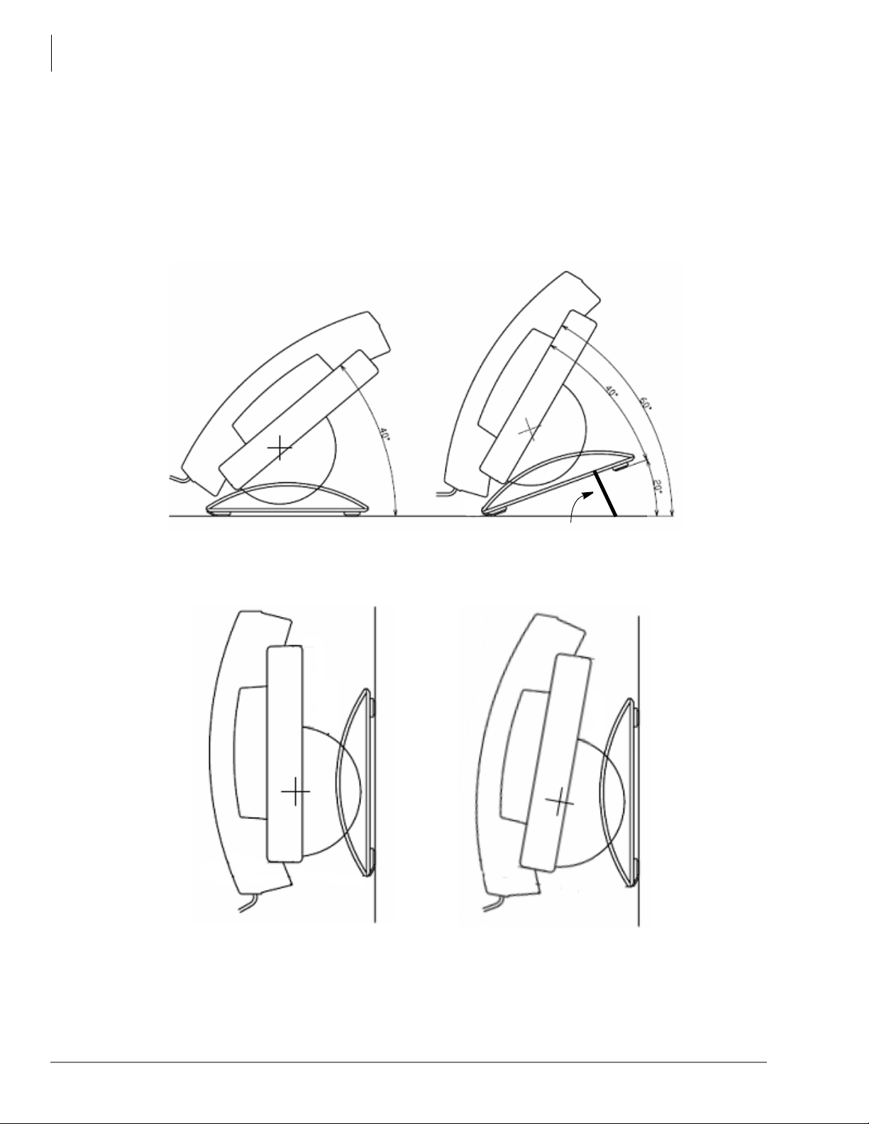
Telephones and Peripherals
Tilt Stand Extension
0° (no) Tilt -10° Tilt
DP5000-series Digital Telephones
DP5000-Series Telephone Tilt Angles
The DP5000-series telephones, except the DP5008, have three tilt positions built into the base.
There is also a tilt stand extension that adds an additional 20 degrees of tilt. When the telephone is
sitting on a desk or table there are a total of six different angles of tilt available. When wall
mounted there are two angles available.
The DP5008 base is fixed at 15 degrees. All other DP5000-series telephones and add-on module
can tilt at 15
Figure 16 DP5000-Series Desk-top Tilt Angle With Tilt-Stand Extension
0
, 27.50, 350, 400, 47.50, and 600.
Figure 17 DP5000-Series Wall Mount Angles
50 Strata CIX General Description 04/13
Page 73
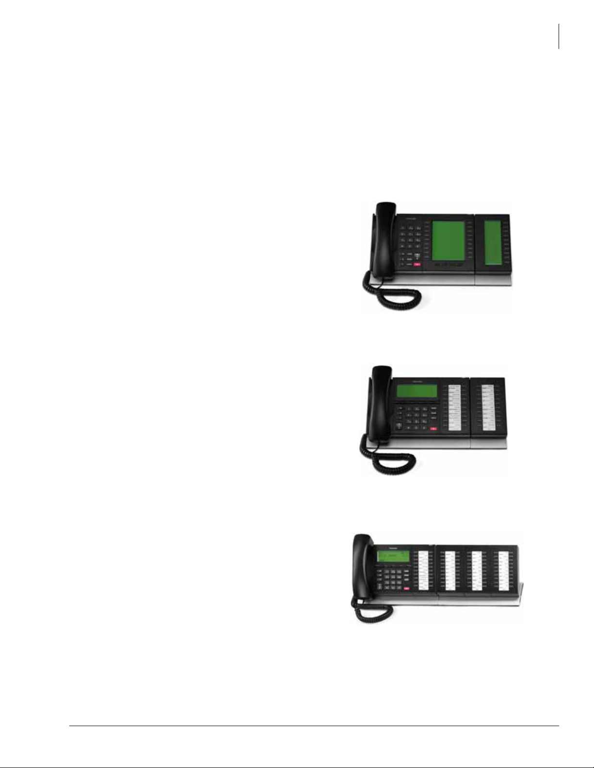
Telephone Button Expansion Options
LM5110 shown with DP5130 Telephone
KM5020 shown with DP5132-SD Telephone
DDM5060 shown with DP5132 Telephone
Add-on modules connect directly to the telephones and do not require an additional interface
circuit (port). Up to two Add-on-Modules can be attached to a telephone to supplement the
telephone's 10 or 20 buttons.
The CIX supports a limited number of Add-on-Modules per cabinet (see Table 59 on page 209 for
the capacities of different common control units).
Expansion options for the Toshiba DP5000-series telephones are described below:
LCD Add-on -Module (LM5110)
The LM5110 adds 10 pro grammable LCD feature buttons
to the 5000-series telephones, these buttons can be
assigned as CO line, Directory Number , DS S, One Touch,
Speed Dial or any other flexible feature.
The LM5110 supports backlig ht and LCD labels, it can be
connected to any 5000-series telephone (except DP5008).
Telephones and Peripherals
Telephone Button Expansion Options
Key Module (KM5020)
The KM5020 adds 20 programmable feature buttons
to the 5000-series telephones. These buttons can be
assigned as CO line, Directory Number, DSS, One
Touch, Speed Dial or any other flexible feature.
Digital DSS Add on Module (DDM5060)
The DDM5060 console (shown right) is for system
attendants.
The DDM5060 operates alongside a digital telephone
and has 60 programmable feature buttons. These buttons
can be assigned as CO Line, Directory Number, DSS,
One T ouch, Speed Dial or any other flexible feature. The
DDM5060 is not compatible with the DP5008.
Up to eight consoles can operate with one digital
telephone depending on CIX system (See Tab le 59 on
page 209).
The DDM5060 console uses LEDs to indicate call and feature status; the DSS has dual red and
green LEDs to help further define status, such as station in DND status. The DDM5060 console
connects to a digital station port on the ADKU, BDKU, or BDKS card.
Strata CIX General Description 04/13 51
Page 74

Telephones and Peripherals
Cordless Digital Telephones
Cordless Digital Telephones
Toshiba offers three cordless digital telephone models, the DKT2404-DECT, DKT2204-CT and
the DKT2304-CT (see photos in this section). These compact cordless digital telephones bring
mobility and productivity to office telephones. Greater call access cuts down on leaving messages
and playing “telephone tag.”
The DKT2404-DECT delivers the DECT functionality for the Strata series of cordless digital
telephones. DECT technology minimizes any interference between base stations in proximity or
any surrounding WLAN access points.
The DKT2404-DECT provides a 24-character display for better compatibility with the Toshiba
DP5000 Series desk phones versus 16 characters on other cordless phone models. It provid es fou r
programmable keys with an additional four speed dial keys.
The digital cordless telephones operate from the same digital station port as the DP5000-series
digital telephone. They can be attached to a Toshiba DKT3000- or 2000-series corded digital
telephone or used as a stand-alone. If a cordless telephone is attached to a DP5000, the DP5000
must be put into 2000 mode.
Some of the features the cordless models include:
• Liquid Crystal Display (LCD) that wraps using two lines, total of 32 characters
• Ringer and handset volume control
• Single button access to: Conference, Hold, Redial, Message and Transfer features
• Four programmable function buttons
• Charging stand
• AutoStandby
• AutoTalk
• Vibrate ringer alert
• Out-of-range protection
• Low-battery protection system
• Headset jack (2.5mm)
• Stand-alone or DKT operation
• High quality ultra-secure conversation with 32Kbps Adaptive Differential Pulse Code
Modulation (ADPCM) voice code combination.
• Three ring tones
Notes
• They cannot receive Group Pages or All Call Pages.
• The handset and base unit of each cordless telephone is equipped with the same security code.
In order for a handset to operate, it must be installed with the matching base unit.
Below is the feature comparison table of the DKT2404-DECT, DKT2204-CT and DKT2304-CT.
Table 14 DKT2404-DECT, DKT2204-CT and DKT2304-CT Feature Comparison
Feature DKT2404-DECT DKT2304-CT DKT2204-CT
Transmission 1.9 GHz DECT 6.0 900 MHz Digital Narrow Band
Number of Channels 5 Channels 30 Channels 10 Channels
Talk Time 16 Hours 7 Hours 6 Hours
Stand By Time 168 Hours 120 Hours 96 Hours
Battery Type NiMH Battery NiMH Battery Ni-Cd Battery
900 MHz Digital Spread
Spectrum
52 Strata CIX General Description 04/13
Page 75
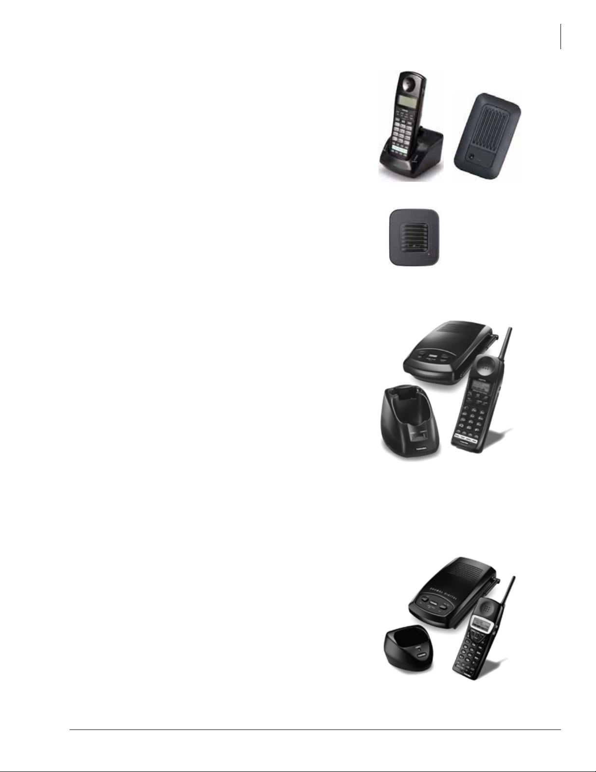
Telephones and Peripherals
DKT2404-UDR100
DKT2404-DECT shown
with charger and Base
6828
6829
Cordless Digital Telephones
DKT2404-DECT
Combined with the DKT2404-UDR100 repeater solution, the
DECT technology provides three to seven times the range
compared to the DKT2204-CT and DKT2304-CT models. Up
to six repeaters can be linked per base station, with up to three
capable of being daisy-chained in one direction, to extend
operation range to greater than 1000 feet in open areas.
The DKT2404-DECT battery life is sixteen hours talk time and
seven days standby time.
The DKT2404-DECT Phone provides:
• Two-line LCD with 24-character display, plus one line for
icons.
• Dedicated Ta lk, Redial, Hold, Msg, Cnf/Trn, Menu/MUTE,
Speaker keys.
• Four programmable keys plus four speed dial keys
• Handset measurements in inches: 2.25 wide x 1.0 deep x 6.5 tall. For base and charger
measurements, see Ta bl e 47 on page 199.
.
DKT2204-CT
The DKT2204-CT uses 900MHz Digital Spread Spectrum
Technology. It’s the reduces unwanted interference and
provides superior voice communication security.
The DKT2204-CT provides:
• The range is two to three times greater than
• Good clarity that is indistinguishable from corded
• Maximum security for up to 10 cordless digital telephones
• A wall-mountable separate base and charging unit are
Handset measurements in in ches: 2.2 wide x 1.66 d eep x 8.66
tall. For base and charger measurements, see Table 47 on page 199.
Note The DKT2204-CT works with Strata CIX and Strata DK telephone systems.
DKT2304-CT
The DKT2304-CT uses 900 MHz Digital Narrow Band
technology that provides:
• A range of two to three times greater than conventional
• Good clarity.
• Maximum security for up to 30 cordless digital telephones.
This DKT2304-CT handset is much smaller than previous
models. Measurement in inches: 2.0 wide x 1.25 deep x 5.5
tall. For base and charger measurements, T a b l e 47 on page
199.
analog cordless telephones.
telephones in most environments.
that is almost impossible to scan.
provided with the telephone.
analog cordless telephones.
Strata CIX General Description 04/13 53
Page 76
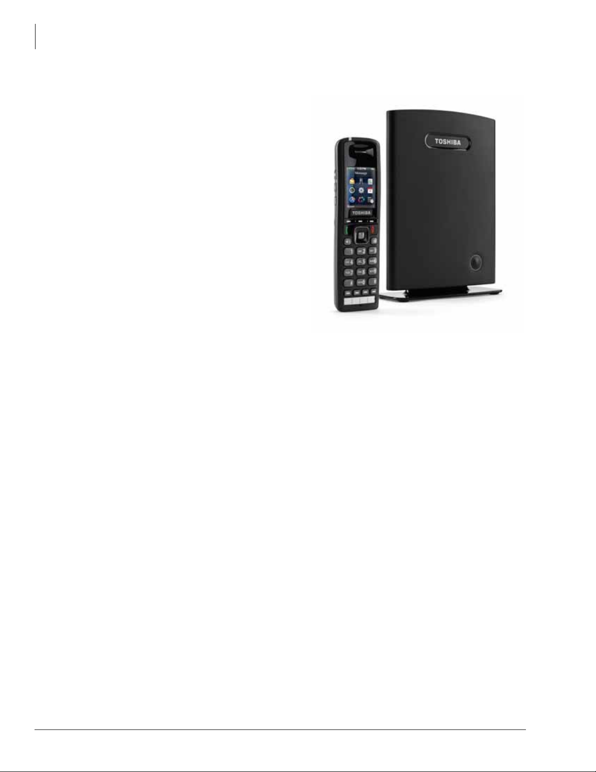
Telephones and Peripherals
IP4100 DECT Telephone and Base
IP4100 DECT Telephone
IP4100 DECT Telephone
The IP4100 DECT telephone (shown right)
supports 8~10 simultaneous call sessions per
base and allows for seamless roaming between
bases in a multi-base configuration. The High
Definition voice enabled speaker and
microphone allows for crystal clear speech.
The handsets support more than 20 hours talk
time and 200 hours standby time in normal
operations. The IP4100 DECT telephones are
administered via a powerful web-based
management tool that simplifies
administration and installation
Handset Features
• 2.0 inch color TFT back-lit display
• Li-ion battery for long talk time and
standby time
• Wideband Voice (HDSP) Basic and
Extended operations
• Over-air feature upgrade support
• DECT 6.0 frequency support with
encryption
• Back-lit keypad for easy operation in low-lit environments
• Laser-etched keypad numbers for extended life use
• Three soft keys for ease of operation
• Four programmable feature keys for flexibility in operations
• 2.5 mm headset jack
• Polyphonic ringer support
• Vibration ring support
• Additional battery charging station in handset charger
• High-quality speaker phone
• Belt clip
.
IP4100-BASE Features
• Attractive design
• Power over Ethernet support
• Omni-directional internal antenna for flexible installation options
• Antenna diversity switching to avoid interference
• Frequency support 1920-1930mhz with Wi-Fi avoidance technology
• Colored LED status indication for ease of installation and operation
• Easy installation via web GUI interface
• Built-in trouble-shooting tools.
54 Strata CIX General Description 04/13
Page 77

IP 5000-Series IP Telephones
The IP5000-series telephones replace the IPT2000-series telephones in the Toshiba product line.
IPT2000- and IP5000-series telephones can coexist with full functionality in one Strata CIX
system, Release 5.2 software, or above.
The IP5000-series telephones have three operational modes:
• When connected to Release 5.2 CIX systems with LIPU or MIPU interface cards, they will
automatically run in IP5000-series mode.
• When connected to CIX systems with older than Release 5.1 (including Release 3), the IP5000series telephones will automatically act as IPT2000-series telephones.
• If the interface is a BIPU-M, the IP5000-series telephones will run in IPT2000-series mode.
Strata CIX40, CIX100, CIX200, CIX670, an d CIX1200 systems running R4 and later software can
upgraded to Release 5.2 software. Systems running R3 must be updated to R4 processors then
updated to R5.2.
Strata CTX28 systems do not support IP telephones.
Toshiba offers five IP Telephone models with backlight displays (except IP5022-SD), full-duplex
speakerphones, and Gigabit Ethernet:
Telephones and Peripherals
IP 5000-Series IP Telephones
• IP5122-SD & IP5622-SD – 10-button IP speakerphone with 4-line x 24-character backlit
LCD. The IP5622-SD does not support Gigabit Ethernet, ADM, DSS, BESCB and carbon
handset/headset.
• IP5022-SD & IP5522-SD – 10-button IP speakerphone with 4-line x 24-character LCD
(without backlight)
The IP5022-SD & IP5522-SD have all the same characteristics as our IP5122-SD except the
backlight for the display. These telephones still have full feature functionality with its 4-line
display and 10 programmable buttons. However, the IP5022-SD supports Gigabit Ethernet,
while the IP5522-SD does not support Gigabit Ethernet, ADM, DSS, BESCB and carbon
handset/headset.
• IP5122-SDC – Looks and functions similar to the IP5122-SD telephon e when connected to the
Strata CIX. This telephones fully support all the Strata CIX features and services of a regular
IP5122-SD telephone. However, this telephone can have a unique feature button called the
Analog Central Office (ACO) button to connect directly to your local Central Office. This
ACO feature enables you to make Emergency 911 calls and/or calls on your direct CO line by
bypassing your Strata CIX system. Power over Ethernet (POE) or AC power is required for the
telephone’s analog local line connection to operate.
• IP5132-SD – 20-button IP speakerphone with 4-line x 24-character backlit LCD
• IP5131-SDL & IP5631-SDL– 20-button IP speakerphone with 9-line x 24-character backlit
LCD and HTML interface with navigation key. This telephone has 18 Soft Keys located on the
sides of the large LCD to respond to the Strata CIX feature prompts, ten of these are
programmable feature buttons. The Shift key (Purple key) toggles the LCD screen between
flexible keys 1~10 and flexible keys 11~20. The IP5631-SDL does not support Gigabit
Ethernet and carbon handset/headset.
Note ACD and FeatureFlex application keys are not supported on programmable feature buttons
11~20 of the large 9-line display telephone.
Strata CIX General Description 04/13 55
Page 78
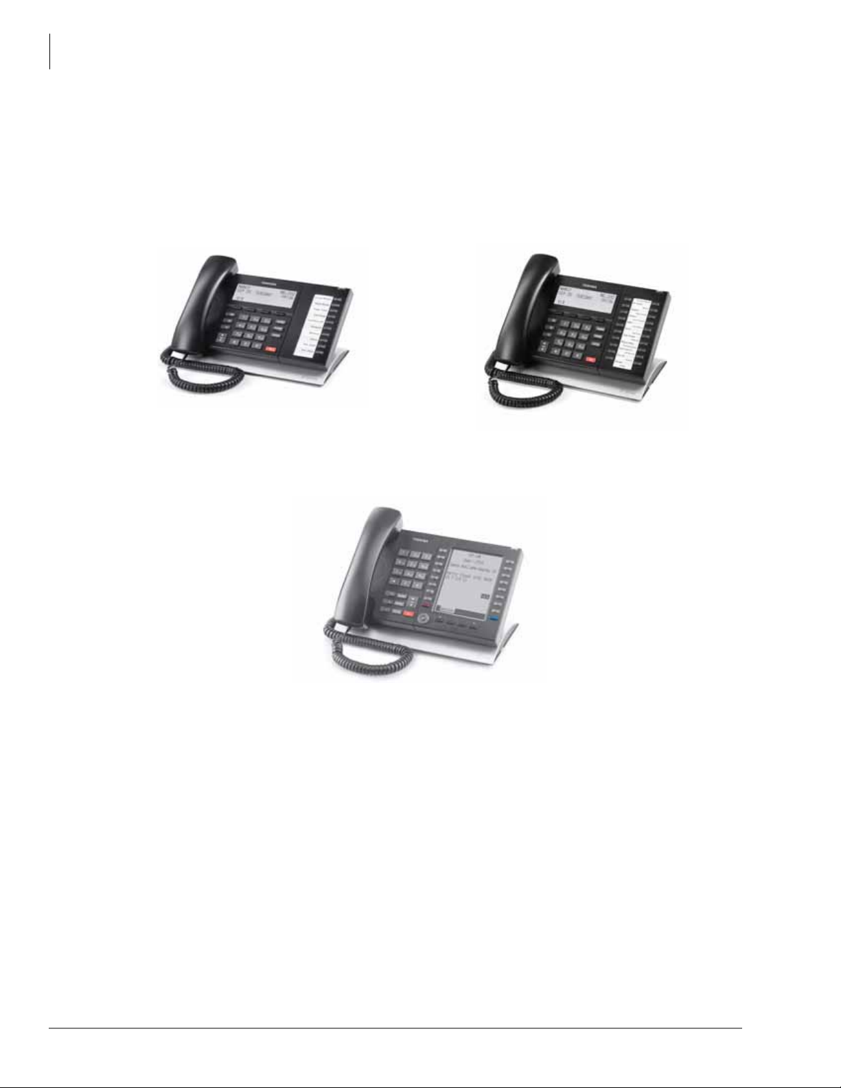
Telephones and Peripherals
IP 5000-Series IP Telephones
IP5022-SD & IP5522-SD
10 programmable buttons, 4-line LCD
IP5122-SD, IP5122-SDC & IP5622-SD
10 programmable buttons, 4-line backlit LCD
IP5131-SDL & IP5631-SDL
20 programmable buttons, large backlit LCD
with HTML support and navigation key
IP5132-SD
20 programmable buttons, 4-line backlit
LCD
56 Strata CIX General Description 04/13
Page 79

Telephones and Peripherals
IP 5000-Series IP Telephones
Features
The IP5000-series telephones include a speakerphone and are 802.3af standard compliant for
Power-Over-Ethernet (PoE). The IP Telephony product family also includes matchin g Add-On
Module and a DSS Console.
The IP5000-series telephones support a very comprehensive and powerful feature set including:
• Backlit Displays (except IP5022-SD)
• Gigabit Ethernet Switch (except IP5522-SD, IP5622-SD and IP5631-SDL telephones)
• Analog Central Office (ACO) button (IP5122-SDC only)
• Busy Lamp Field (BLF) display of station status.
• Background Music through telephone speakers.
• Paging over telephone speakers.
• IPT Anywhere
• Automatic Configuration
• Terminal Authentication (security)
• Off-hook Call Announce (OCA) over telephone handset.
• Speaker OCA when using MIPU / LIPU / LIPS, GIPU or GIPH.
Note IP5000-series telephones enabled with Speaker OCA require two IP channels from the same
IP interface card but only one end point license. The IP channel used for Speaker OCA is
only used during the OCA call and may be shared by all IP5000-serie s telephones.
• Built-in headset interface for headsets and external speaker connection (BESCB)
• IP Add-on Modules (except IP5522-SD and 5622-SD)
In addition, the 5000-series IP telephones contain several important features, including:
• Full-duplex speakerphone capability when using an MIPU / LIPU interface card in a CIX
system.
• 802.3af power over Ethernet compliant
• Integrated Application Processor for Voice Mail, Unified Messaging ACD, and other
applications
• Soft Keys to respond to the Strata CIX feature prompts.
• Additional feature adjustments, such as setting button beeps, room noise sensitivity and
handset busy override tone.
• An adjustable tilt stand base is built-in, providing flexible angle adjustment of the entire
telephone.
IP Protocol
The Strata CIX uses RFC3015 Media Gateway Control (MEGACO) enabling Strata systems to
provide all the feature functionality of digital-series telephones to IP telephone users.
Connectivity
IP telephones connect to either the MIPU, LIPU, LIPS, GIPU or GIPH in the Strata CIX system
running software version 5.2 or above. However, the IPT2008-SDL can only be connected to the
MIPU, LIPU/LIPS GIPU or GIPH. These telephones must be connected to MIPU / LIPU / LIPS,
GIPU or GIPH to use peer-to-peer Real Time Protocol (RTP) connection.
Note The Strata CIX also supports the IPT1020-SD. This telephone can be connected to a
BIPU-M card only. It does not support peer-to-peer RTP connection.
Strata CIX General Description 04/13 57
Page 80

Telephones and Peripherals
IP 5000-Series IP Telephones
• These telephones do not use the System power supply, so there is no power restriction to limit
the number of IP telephones that can connect to an indiv idual S trata system . The IP Telephones
have built-in connectors. The back of the telephone has connector labels. The telephones can be
powered by a local power supply on the PoE (Power over Ethernet).
• The RJ45 LAN jack connects the telephone to the network via the LAN cable supplied with the
telephone. These telephones operate on the network at 10/100Mbps and 1000Mbps (IP5000series with the exception of the IP5522-SD, 5622-SD, 5631-SDL telephones) and can be
connected to a fast switch hub, router, LAN, WAN, etc.
• The RJ45 PC jack can connect the IPTs to the user’s PC. The IPTs can operate like a switch, as
opposed to a hub, so the telephone can be connected directly to the LAN or Cable/DSL modem,
and then a PC can be connected to the telephone PC jack to connect to the LAN through the
telephone.
• The built-in headset jack enables headsets to be connected to the telephone. No optional
headset interface is required. The same carbon or ECM headset support used on Toshiba digital
telephones can also be used on IP telephones.
Capabilities
The Toshiba IP Telephones also have the following capabilities:
• The IPTs contain two types of codecs (coder/decoder): G.711 and G.729A. The codec
determines the IP telephone voice quality and network bandwidth requirements. The G.711
requires the most bandwidth and provides the best voice quality. The G.729A requires less
bandwidth, but it does not provide the best voice quality. The desired codec is selectable for
each IP telephone in IP station administration using eManager or Network eManager.
• The external ringer interface connector is mounted inside the telephone base. This enables
connection of an BESCB external speaker device to provide a loud ringer for the IP telephone.
• All telephones in the system can be IP telephones up to the system’s maximum station capacity
(see Table 59 on page 209).
• Terminal Authentication is an option that allows a particular IP telephone to keep a reserved
directory number on a CIX system. This prevents IP telephones from logging in with another
telephone’s directory number if the other telephone has been disconnected to be taken to
another location. This feature uses the unique Media Access Control (MAC) address that is
permanently coded into each telephone network interface circuit. The unique MAC address of
the telephone is assigned to a particular directory number in system programming.
• IPT firmware can be updated locally or remotely using eManager. This enables service
personnel to update IP equipment with new features and enhancements as they become
available. Updates require a brief interruption of IP telephone operation (a few minutes).
• IP telephones have a discovery retry timer to prevent network congestion when many IP
telephones request services simultaneously. If network congestion is detected, the telephone
will pause and then retry for service.
• IP telephones have loop back and ping capabilities for maintenance and fault finding purposes.
• IP telephones support Dynamic Host Configuration Protocol (DHCP) or static IP addressing.
58 Strata CIX General Description 04/13
Page 81

Telephones and Peripherals
IP 5000-Series IP Telephones
Liquid Crystal Display (LCD) Models
The IP5022-SD, IP5122-SD, IP5522-SD, IP5622-SD, IP5122-SDC and IP5132-SD models
display up to 24 characters times four lines of information and provide four Soft Keys.
The IP5131-SDL, IP5631-SDL has 4 soft keys and a 9-line LCD. From the idle screen you can
access telephone directories and speed dial lists of names or departments, internal or external to
the telephone system. You can search by name or letter within a list.
The IP5131-SDL screen consists of Phone, Config, and Web-application screens. The screens
change easily by pressing the tab soft key.
• Phone screen – This screen is a 150 x 168 pixel LCD screen.
• Config screen – This screen can be used for Telephone configuration settings. Using this
screen, you can set the IP address, subnet mask, etc.
• Web screen – provides users with the access to the web page. This capability can be used to
create the custom applications designed to match with IP5131-SDL phone screen so that the
user can enter or retrieve the data from the IP5131-SDL phone.
All LCD telephone models can provide:
• Advisory Messages
• Automatic Number Identification (ANI)
• Caller ID, Name and Number with call history
• Contrast adjustment (13 levels)
• Backlight adjustment, except IP5022-SD (On/Off/Synchronized)
• Date/Time of Day
• Dialed Number Identification Service (DNIS Name and Number)
• Feature Prompting Soft Keys that are used as an alternative to access codes or feature buttons.
Station users can access features by responding to LCD prompts.
• Called Number displays on outgoing calls (1~120 secs.)
Strata CIX General Description 04/13 59
Page 82
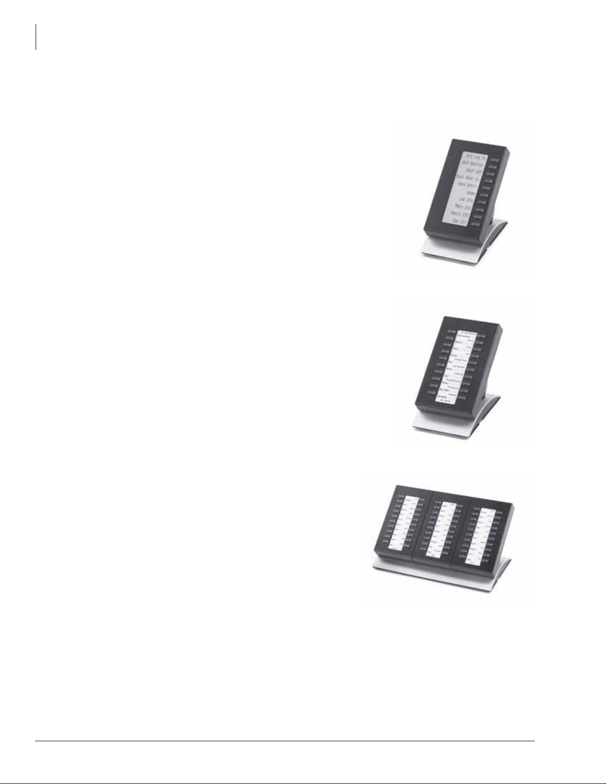
Telephones and Peripherals
Telephone Button Expansion Options
Telephone Button Expansion Options
Upgrade options for the Toshiba IP telephones are described below.
LCD Add-on Module (LM5110)
The LM5110 adds 10 programmable LCD feature buttons to
the 5000-series telephones (except the IP5522-SD and IP5622SD telephones), these buttons can be assigned as CO line,
Directory Number, DSS, One Touch, Speed Dial or any other
flexible feature.
The LM5110 supports backlight and LCD labels, it can be
connected to any 5000-series telephone (except DP5008).
Key Module (KM5020)
The KM5020 adds 20 programmable feature buttons to the
5000-series telephones. These buttons can be assigned as CO
line, Directory Number, DSS, One Touch, Speed Dial or any
other flexible feature.
IP Direct Station Selection (IDM5060) Console
The IDM5060 console (shown right) is for system
attendants.
The IDM5060 operates alongside a IP telephone and has
60 programmable feature buttons. These buttons can be
assigned as CO Line, Directory Number, DSS, One
Touch, Speed Dial or any other flexible feature.
Up to three consoles can operate with one IP telephone
depending on CIX system. However , the IP55 22-S D an d
IP5622-SD telephones do not support an IDM.
The IDM5060 console uses LEDs to indicate call and feature status; the DSS has dual red and
green LEDs to help further define status, such as station in DND status. The IDM5060 console
connects directly to an IP5000-series station.
60 Strata CIX General Description 04/13
Page 83

CIX Attendant Console
The Strata CIX Attendant Conso le runs on a PC with Microsoft® Windows® 2000 Professional or
Windows XP Professional operating system. The Strata CIX Attendant Console PC is equipped
with an Intel two gigahertz CPU in a small, compact desktop chassis that is just the right size for a
receptionist’s desk. If there isn’t any room on the desk for the system to lay flat, it can also be
stood on its side for an even smaller footprint. Add to that the powerful Strata CIX Attendant
Console software, and you have a winning solution for any Strata CIX installation!
The Console connects to the Strata CIX processor via the LAN as a Computer Supported
Telephony Application (CSTA). The Strata CIX system requires the processor NIC interface.
Each CIX Attendant console requires the LIC-ATT license which is bundled with the Toshiba
supplied Attendant Console PCs and software. The LIC-ATT license must be ordered separately to
enable the Console to be installed on a Dealer / Customer supplied PC. The latest Attendant
Console software is available at no charge on Toshiba FYI.
The minimum PC requirements for the CIX Attendant Console are:
• Operating Software – Microsoft Windows XP Pro or Windows 2000 Pro
• Processor – 2.0GHz Intel Pentium 4, Celeron or higher
• Memory – 512M RAM
• CD-ROM Drive, CD-R/W Drive or DVD capable of reading CD-ROM data files to install
Attendant Console software.
• Hard Drive: 500M space available
• Sound card with internal or external speakers
Telephones and Peripherals
CIX Attendant Console
There are two types of CIX Attendant Consoles; each operates and functions the same but each
provides a different type of talk-path.
The following Attendant Console hardware is available from Toshiba:
• CIX-DATTCONS – provides a digit talk path like a digital telephone and requires a BDKU
interface port. Includes software and LIC-ATT lic ense.
• CIX-IPATTCONS – provides an IP talk path like IP telephones and requires an MIPU / LIPU
interface port. Includes software and LIC-ATT lic ense.
Each of the above CIX Attendant Consoles consists of the following standard items:
• Attendant Console License (LIC-ATT) for the CIX processor (bundled with Toshiba Console
part number)
• LIC-ATT must be ordered separate ly if using a Dealer supplied PC for the Attendant Console
• Intel 2.8 GHz CPU
• 512M Random Access Memory (RAM)
•CD R/W drive
• Windows 2000 Professional (factory installed)
• CIX Attendant Console software (factory installed)
• Comprehensive set of multimedia inputs and outputs
• Keyboard & Mouse
• PC Headset (CIX-IPATTCONS only)
• Attendant Keyboard stickers (Black) CIX-BL-ATCON-VA
Strata CIX General Description 04/13 61
Page 84

Telephones and Peripherals
CIX Attendant Console
The optional items are:
• Printed documentation is available on Toshiba FYI, as well as Documentation downloads.
• 17” Flat screen Monitor – Toshiba offers a 17” Liquid Crystal Display (LCD) flat screen
monitor; part number CTX-LCD-MONITOR.
• Attendant Console Interface Unit (BATI) and Handset/Cradle (BATHC) connects to a digital
telephone interface port on the Strata CIX (CIX-DATTCONS only). An optional headset can be
used in conjunction with the handset.
...or
a DKT3001 or DP5008 can be used as the console handset instead of the BATI/BATHC
handset/cradle. If an optional headset is used, it connects to the optional BHEU installed in the
DKT3001 or directly into the DP5008 built-in headset jack (CIX-DATTCONS only).
Important!
• If a digital telephone is used in place of the BATI/Handset, it can be used as the Attendant
Console Handset only. It cannot be used as a telephone to make or receive calls ind ependent of
the console. This includes when the console is in service or out of service.
The Strata CIX1200 supports up to six, the CIX670 system supports up to four, and the CIX200,
CIX100 and CIX40 supports up to two Attendant Consoles. Multiple consoles automatically share
the incoming call load on a call-by-call rotation basis. Features such as Overflow and Position
Busy add to the efficiency of single or multiple console applications.
62 Strata CIX General Description 04/13
Page 85
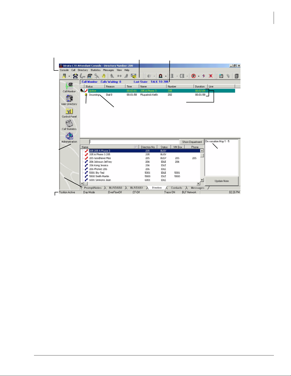
Telephones and Peripherals
Menu Bar
Info Bar
Toolbar Icons
Call List
Call Status
icons
Call Attributes
(See Appendix
for definitions)
6594
View
Pane
Icons
Notes
Call
Monitor
Tabs
Directory
Status Bar
CIX Attendant Console
The CIX Attendant Console is designed to handle all call activity within a single Call Monitor
screen, shown below. All calls will appear in a single list.
Calls are marked with icons to show the current status.
Features such as Paging, Call Pickup, Call Park offer many alternatives. The Administration
window enables which option is the primary operation for that Attendant. For example, if two
zones are used for paging, as well as the All Call, then an option pull down arrow is next to the
icon. Clicking the icon starts the All Call Page, then the Attendant can select one of two page
zones.
All other views available for the Attendant are for administrative and management use. They do
not control any type of call handling except how chosen options affect the overall operation.
The CIX Attendant Console also enables an attendant to manage console settings, maintain a user
directory, and view call statistics. The Console provides a Name/Number search that works with
automatic or manual call handling. Other features include Queuing, DSS, signaling, Emergency
Call ID, keyboard or mouse operation, and headset or handset operation with volume control.
Strata CIX General Description 04/13 63
Page 86
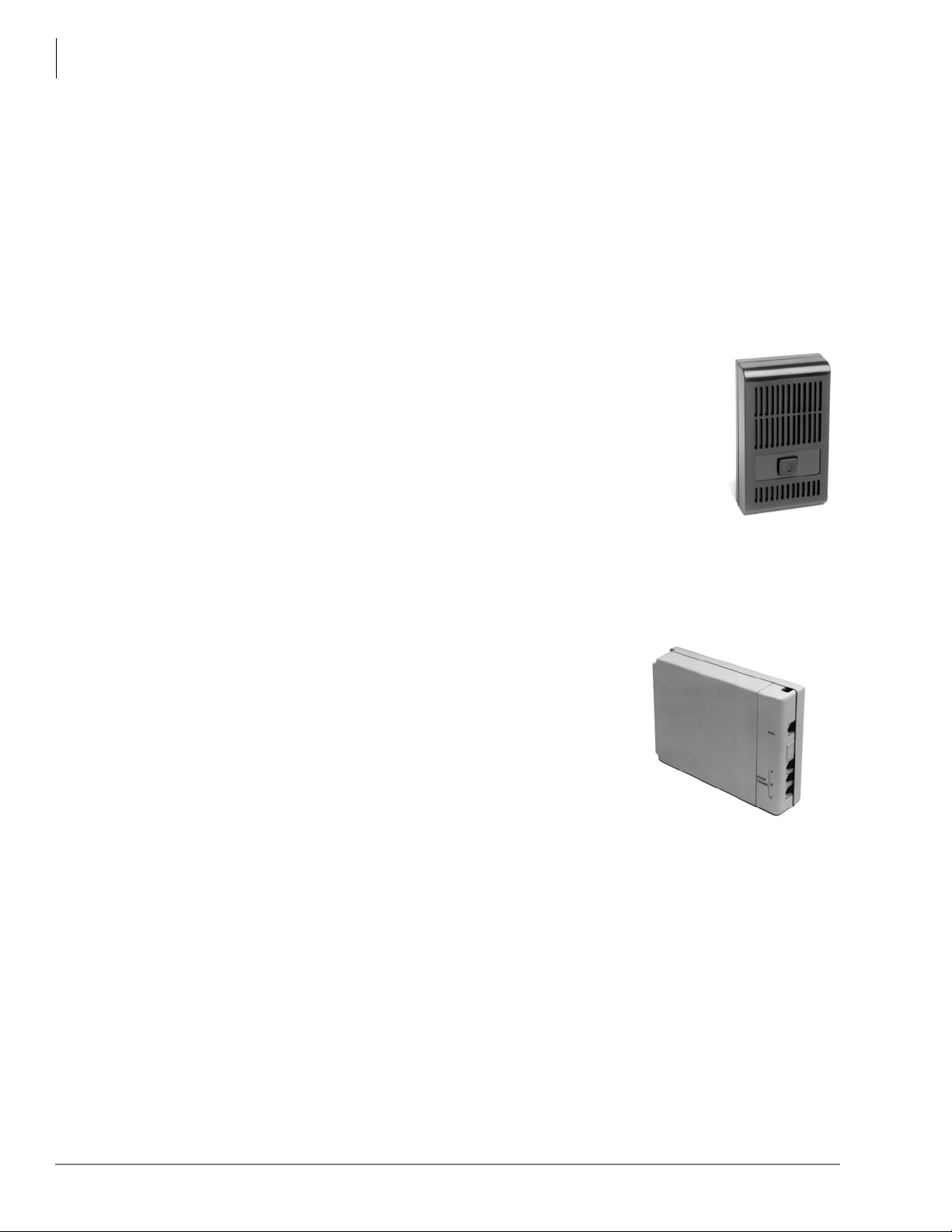
Telephones and Peripherals
1873
1874
Peripherals
Peripherals
The Strata CIX supports several types of stations and customer-supplied peripheral devices, such
as door phones for visitor screening, a music source interface for MOH and BGM, a speaker for
amplified ringer, Toshiba Voice Processing systems for voice mail/auto attendant applications,
and more.
Toshiba Telecommunication Systems Division (TSD) does not provide ISDN or IP station
equipment, such as ISDN IP telephones, fax machines, and computer interface devices for high
speed Internet access or video conferencing. Toshiba does provide the interface circuit boards that
support all of the above ISDN station equipment.
Door Phone (MDFB)
Door phones can be assigned to ring telephones when the button on the door
phone is pressed. The Door Phone location displays on the called telephone’s
LCD. When the telephone answers, a two-way talk path exists between the
telephone and door phone.
Door phones can also be used as sound monitors. Station users can call the
door phone (it will not ring) and listen to sounds from the surrounding area.
Door phones also can operate as a “hot line.” For example, a door phone can
be used for calls between an office and a warehouse. Door Phones are often
used with a door lock to screen building visitors. The door lock can be opened
for a predetermined amount of time by pressing a button on a telephone.
Door Phone/Lock Control Unit (DDCB)
The DDCB can support as many as three door phones (MDFBs)
or two door phones (MDFBs) and one door lock control relay.
Using the door lock control, digital station users can unlock a
customer-supplied electronic door lock at the touch of a button
programmed on their digital telephone or by dialing a feature
access code from any type of telephone. Each DDCB requires
one digital station circuit.
Each door lock can be programmed to remain open between
three~30 seconds. The Door Lock button LED remains On while
the lock is open. LCD telephones display “DOOR
UNLOCKED” until the telephone releases or times out.
External Speaker (BESCB)
The BESCB is a multi-functional, external, speaker control box with a built-in three-watt
amplifier. It can be used to control and drive a pa ging speaker, a paging amplifier, or a telephone’s
Loud Ringer.
64 Strata CIX General Description 04/13
Page 87
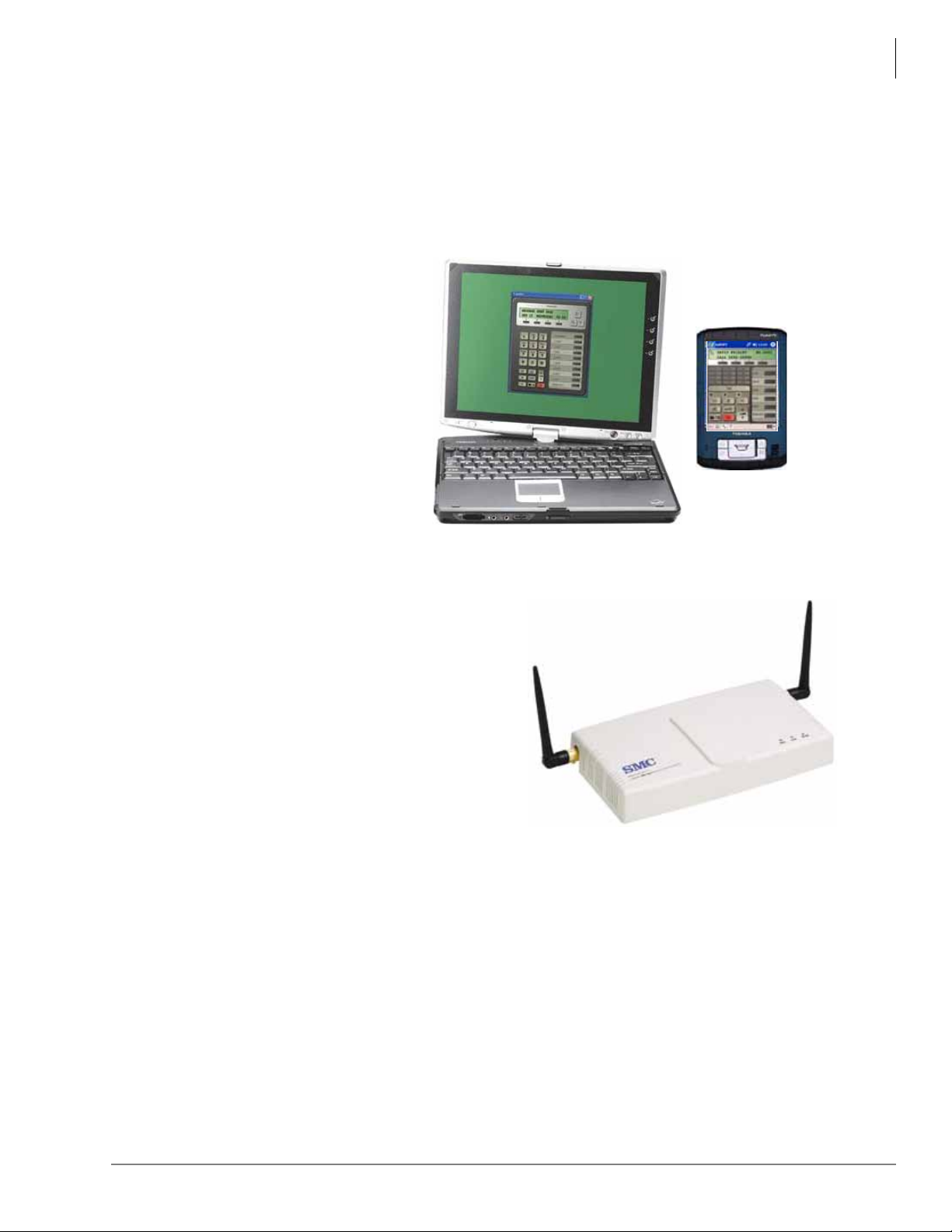
Mobility Solutions
SoftIPT for PDA
SoftIPT for Laptop/Tablet
SMC EliteConnect 2.4 GHz
802.11g Wireless Access Point
(SMC2552W-G)
Toshiba mobility solutions maximize the value of the customer’s wireless Local Area Network
(WLAN) by using their existing WLAN infrastructure. This makes very cost-effective mobility
solutions possible with Strata CIX solutions.
SoftIPT
For more details, see “Toshiba
SoftIPT IP Telephone” on page 156.
Telephones and Peripherals
Mobility Solutions
Wireless Access Points
Toshiba has a strategic relationship with SMC
Networks, a leading provider of networking
solutions for the small and medium business
markets to market a host of SMC Networks wired
and wireless networking products through
authorized Toshiba dealers. As part of providing a
total solution, you can purchase SMC wireless
access points from Toshiba and package them with
Strata CIX solutions.
Toshiba supports the SMC EliteConnect 2.4GHz
Wireless Access Point. This access point sized and
priced to fit well with Strata CIX systems to serve
wireless LAN applications in which customers want
to install new or expand the capabilities of their
existing wireless LAN.
Features and specifications:
• IEEE 802.11b and 802.11g compliant
• Data rates up to 54 Mbps in 802.11g, and 11 Mbps in 802.11b with auto-fallback feature
• High configurable transmit power up to 100mW
• Support up to 64 users
• Enterprise level of authentication and encryption security
• Flexible management features including Command Line Interface (CLI), Web-based
management, SNMP, Syslog, and Event Logging
• Detachable antennas for optional external 2.4GHz high gain antenna
• Power over Ethernet
• Anti-theft mechanism
Strata CIX General Description 04/13 65
Page 88
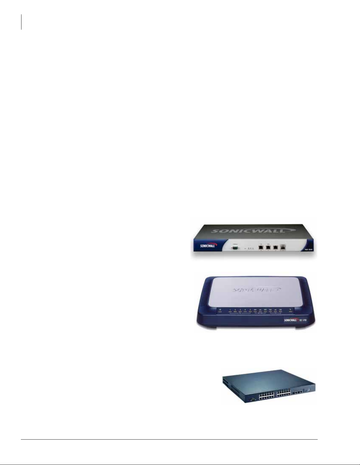
Telephones and Peripherals
7868
Pro 2040
7869
TZ-170
SMC3526-PoE
Mobility Solutions
VPN/Firewall Solutions from SonicWALL
Toshiba has a strategic relationship with SonicWALL, one of our industry’s leading suppliers of
network security firewall products, to re-sell the SonicWA L L Pro series of firewall products
through authorized Toshiba dealers. As part of providing a total solution, you can purchase
firewall products from Toshiba to create tightly intergrated converged voice and data solutions
using the Strata CIX.
The Pro 2040 is SonicWALL’s new entry model into the high-performance PRO appliance series
for small configurations, typically up to 150 users. The PRO 2040 is tailored for small to mediumsized businesses requiring a high level of security performance and features, but still requiring
ease-of-use and an affordable price.
Features and specifications:
• 200Mbps Firewall, 50Mbps VPN.
• Up to 4 10/100 Base-T Ports.
• Hardened Platform with Redundant Fans.
• 150 Total VPN Tunnels.
• Intrusion Prevention Services
• VoIP Support
• Enhanced Load Balancing, Fail-over.
• Enhanced Deployment Flexibility.
• Enhanced NAT Modes.
The TZ-170 (shown right) is SonicWALL’s
solution for firewall and VPN capability for
remote and branch offices. The TZ-170
provides the same features and administration
interface as the larger 2040, but at the right size
for smaller sites.
• 10, 25 and unlimited user configurations
• 90 Mbps Firewall
• Up to 10 VPN tunnels
• Seven Ethernet ports
• Intrusion Prevention Services
• VoIP support
Power-Over-Ethernet Solutions from SMC
Toshiba has a strategic relationship with SMC to re-sell the
24-port, 802.3af certified SMC6824MPE PoE switch
through authorized Toshiba dealers.
The SMC6824MPE PoE switch is sized and priced to fit
well with Strata CIX systems to serve applications in which
customers want to power their IP telephones over Ethernet,
instead of using local power with each IP telephone.
66 Strata CIX General Description 04/13
Page 89

Video Communication Solution
The Strata Video Communication Solution (VCS™) is designed to provide Strata users with an
integrated collaboration tool, including point-to-point 8-party video conference, 3-party
collaboration (desktop and applications sharing), 8-party file transfer, and 3-party message board
capabilities to make video communication and collaboration more powerful than ever!
VCS has many Graphical User Interface (GUI) enhancements. It provides a more valuable and
complete Strata IP solution. QoS is included and the GUI on VCSManager has changed to make
configuration and VCS setup more intuitive.
Visual Collaboration
8-party conferencing with 3-party Video conferencing takes productivity to a new level. While a
total of eight parties are on a call, three parties can also see, hear, interact and collaborate on
projects together, no matter where they are physically located. VCS provides a way to conduct
remote virtual meetings, work group discussions, and much more.
During the voice conference, any of the three parties can initiate application sharing, edit a file,
send and receive files, and send text to a message board. These great tools will dramatically
increase productivity and quality of work, while reducing the cost of business travel.
Telephones and Peripherals
Video Communication Solution
Try VCS for FREE
Strata CIX/MAS customers can also enjoy VCS FREE with the 90-day trial license.
Just order and activate the trial license on your MAS to try VCS. After the free trial period expires,
VCS permanent licenses can be purchased. The MAS requires a memory upgrade to 1GB to
support VCS.
VCS Features
Combined with all the features in VCS 2.0, and enhanced to support up to 8-party VCS user
applications, VCS 3.0 is an attractive voice conferencing, video conferencing, and collaboration
solution for today’s demanding Strata customers.
The following are highlights of features available in VCS 3.0.
• Fully integrated with the Strata CIX system – VCS Server software is pre-installed on the
Strata Media Application Server (MAS). VCS Windows XP client software easily extends the
Strata CIX voice user’s multi-media experience.
• Point-to-Point 3-party Video Conferencing – A cost effective solution, multi-party video
conferencing is achieved without any additional hardware. VCS runs as an application on the
MAS. Various window layouts and options are available for customization. Automatic
interface makes video conferencing easy to use and easy to manage. In a conference with more
than three parties, any three parties can be selected to have the video.
• 8 way Collaboration – Desktop, application, and document can be shared by up to 8 VCS
users. All users can edit the same materials while in session (one editing at a time).
• Session Member List (SML) – Displays VCS members who are logged on and have
established voice communication with you. You can easily select members from this list to
begin any VCS collaborative sessions.
• 8 way File Transfer – Users can send and receive multiple files to other VCS users.
Strata CIX General Description 04/13 67
Page 90
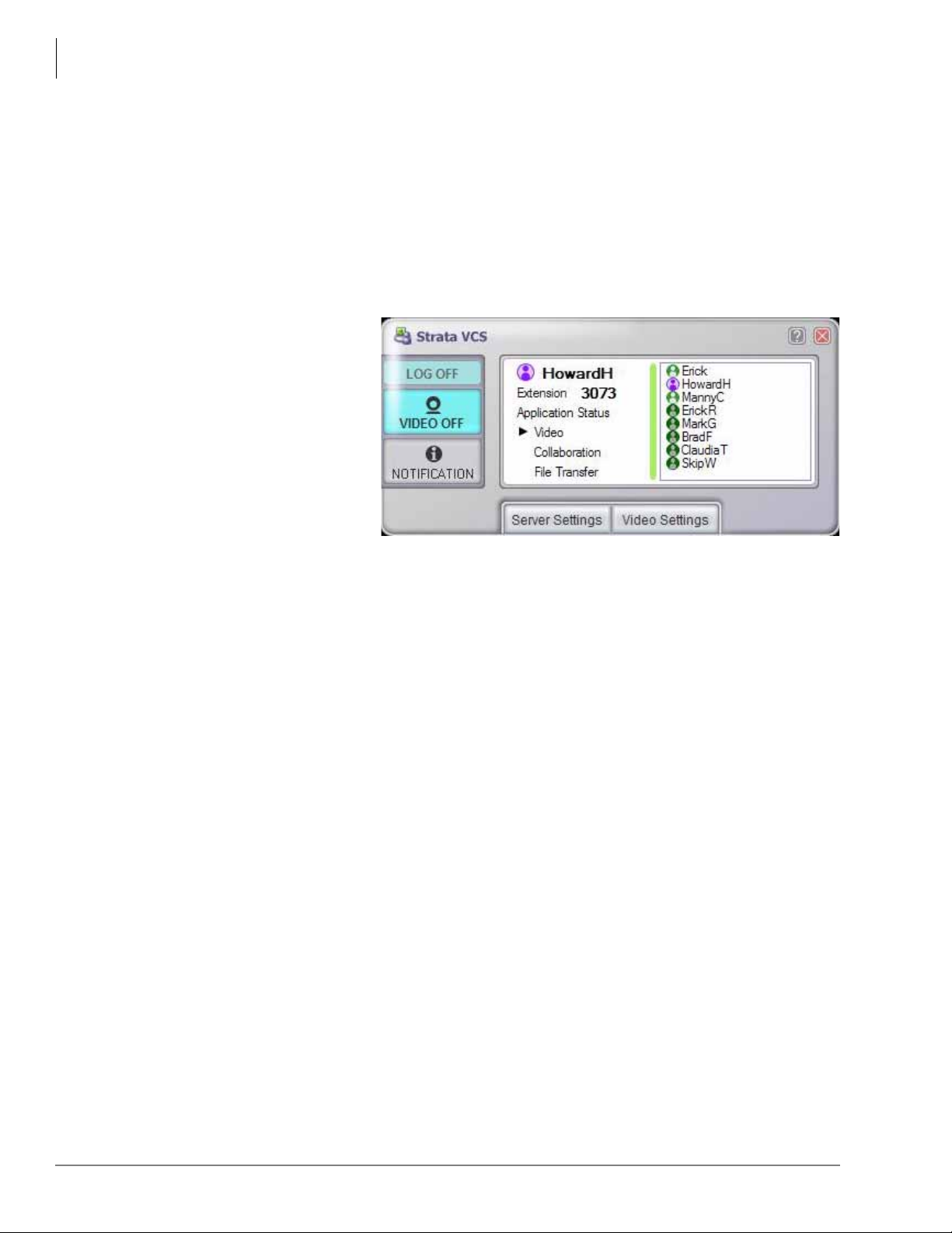
Telephones and Peripherals
Video Communication Solution
• 8 way Message Board (Chat) – Users can post text and chat on a message board, as an
alternative to communicating verbally.
• Support for QoS – If the customer’s network equipment is end to end, Diffserv Priority
control can be enabled for all the clients from VCSManager. This system setting will give
Video, Collaboration and File Transfer media a higher priority.
• V ideo Setting Control – Similar to QoS setting, VCS administrator can control the upper limit
of video bandwidth via VCSManager for all VCS clients.
VCS functionality is integrated with the Strata CIX telephony capabilities, with features
specifically tailored to handle video telephony, including:
• Call Hold/Retrieve
• Call Transfer
• Call Forward
• Station Hunting
• Call Park/Retrieve (Calls
can be parked on the local
node only.)
• Call Pickup/Retrieve
• Up to 3-way video with
8-way voice conference
• Manually select default Video Setting and Video display default On or Off
• Automatic Start VCS after Windows log on and Automatic VCS log on after VCS application
started
• Self Video preview
Software
VCS Server software is pre-installed on the Strata MAS with Windows XP Pro. Existing Strata
CIX/MAS customers can also install VCS software on their MAS.
VCS Client software runs on each user’s Windows XP Home or Pro computer. Client software is
provided together with VCS Server software on the Strata MAS.
VCS Software Upgrade
VCS 3.0 is compatible with Strata CIX Release 5.0 or later systems.
• Older versions of Strata CIX must be upgraded to Release 5.0 before upgrading VCS software
from version 1.0 to 2.0.
• VCS 2.0 software can upgrade to VCS 3.0 FREE of charge.
Licenses
See Chapter 8 – Strata Media Application Server and Integrated Voice Mail Cards, Table 19 on
page 79 for VCS Licenses.
68 Strata CIX General Description 04/13
Page 91

Product Specifications
Item Specification
Strata CIX Release 5.0 or later
Multiple Strata CIX nodes must be networked via Strata Net
Telephones and Peripherals
Product Specifications
Endpoints
VCS Client PC
Requirements
Accessories USB Camera: Re com m e nd usin g Lo git ec h QuickCam Pro 5000 or
VCS Server Hardware
Requirement
VCS System
Capacities
Strata Digital Telephones, Strata IP T elephones and Soft Phones
CPU: PentiumM 1.5GHz or greater
Memory: Minimum 512MB
Free hard disk space: 10MB
100 Base - TX Network Interface Card
Windows XP Home or Pro with SP1, SP2, SP3, Vista SP1
Direct X Version 9.0c or later (and compliant video graphics card)
QuickCam for Notebooks Pro
MAS, 2U MAS or MicroMAS
1GB RAM
Minimum Free hard disk space: 120MB
VCS server can support:
Max Number of CIX nodes (based on RAM): 9 (1GB)
Number of configured users: Limit to available Disk space
Maximum activated user licenses: 480
Maximum logged on users: 480
Maximum Number of VCS clients active sessions (stations): 480
Video Standards: MPEG4
Output Format: VGA, QVGA, QCIF Encoding Bit Rate: 128kbps to 1.5Mbps
Video Frame Rate: Auto adjust up to 30 fps
Protocols Signaling: Client/Server – SIP RFC 3261
Networking: TCP/IP v4, FTP, HTTP
Client: UPnP
Server: CSTA
Administration Web based VCSManager: VCS server information settings, CIX Profiles
settings, User information settings, QoS settings, System Video Settings,
Administrator information, VCS license activation, log files - to local disk or
transfer log files using FTP, backup and restore system data, display
operation status (User and Server status, Version information, maximum of
user licenses purchased and number of active users logged on.
Log file size: 450MB in HDD per CIX
VCSManager manages one VCS server. One VCS server can handle
multiple Strata CIX nodes.
Warranty Software is “AS IS” without warranty of any kind.
Strata CIX General Description 04/13 69
Page 92

Telephones and Peripherals
Toshiba Stratagy Voice Processing
Toshiba Stratagy Voice Processing
The Strata CIX can operate with Toshiba Stratagy voice processing systems, which provide a
number of helpful messaging and related features. The Strata CIX supports in-band DTMF voice
mail integration and requires DTMF receivers. It also supports standard SMDI and Toshiba
Proprietary voice mail integration. Refer to the appropriate Stratagy literature for details.
All Stratagy systems provide these essential applications:
• Automated Attendant to answer incoming calls without receptionist assistance
• Call Routing to direct callers to specific extensions or departments they want
• Telephone Answering to take messages when an employee is unavailable
• Voice Messaging to create, send, receive, forward, and save voice messages
• Audiotext to play pre-recorded information on demand
• Call Screening to announce the calling party
• Message Notification to let you know when messages are left
• Token Programming to customize your Stratagy voice processing functions
Stratagy gives you the ability to:
• Simplify voice mailbox operation through a Strata CIX telephone with LCD display and soft
keys
• Record calls directly into your voice mailbox with a single button on your telephone
• Manage voice, fax, and e-mail messages from your PC or telephone via Unified Messaging
• Add advanced options as needed to support Fax Integration, Text-To-Speech, Speech
Recognition, and Interactive Voice Response applications
• Communicate effectively both in and out of the office with other employees and customers 24
hours-a-day, 365 days-a-year
From basic to sophisticated, Toshiba Stratagy voice processing delivers a variety of voice mail
choices to select what’s best for your business.
Stratagy iES16, and iES32 models seamlessly integrate your voice message processing on a single
printed circuit card inside your Strata CIX system—with no need for external connections,
standard telephone ports, or separate power backup systems.
Toshiba’s Strata Media Application Server supports voice processing and all value-added
applications integrated within one platform that connects to the Strata CIX via Ethernet.
Applications include Auto Attendant, Voice Mail, Automated Speech Recognition (ASR), Text-toSpeech, Unified Messaging, Interactive Voice Response (IVR), Automatic Call Distribution
(ACD), ACD Reporting, Toshiba-approved 3rd party CTI applications, FeatureFlex adaptability
tools, and browser-based system administration.
70 Strata CIX General Description 04/13
Page 93

Cabling and Connectors
The Strata CIX uses industry standard cabling and connectors to interface with lines, stations, and
peripherals. Stations use standard twisted-pair cabling to connect to the system via the MDF.
Digital and standard telephones require just one pair-cabling. Two pairs may be required to
achieve full distance when optional DP subassemblies are used.
Digital telephones connected to BDKS require an external power supply to reach maximum
distance from KSU when the telephone has a DADM or DOCA-1A.
Station circuit cards connect to stations and peri pherals with a 25-pair Amphenol connector via the
MDF. Analog CO, DID, and Tie line circu its interface with the public telephone network via
modular connectors. T1 and ISDN use industry-standard Amphenol and modular connectors (for
details, see Table 43 on page 196).
Peripheral devices such as eManager maintenance PCs, etc., connect to a hub or LAN, which
connects to the processor’s Ethernet LAN interface via an RJ45 connector and Category 5 wiring.
Call Accounting and Voice Mail SMDI require RS-232 modular adapters and cords to connect to
the processor BSIS interface.
Telephones and Peripherals
Cabling and Connectors
Strata CIX General Description 04/13 71
Page 94

This page is intentionally left blank.
Page 95
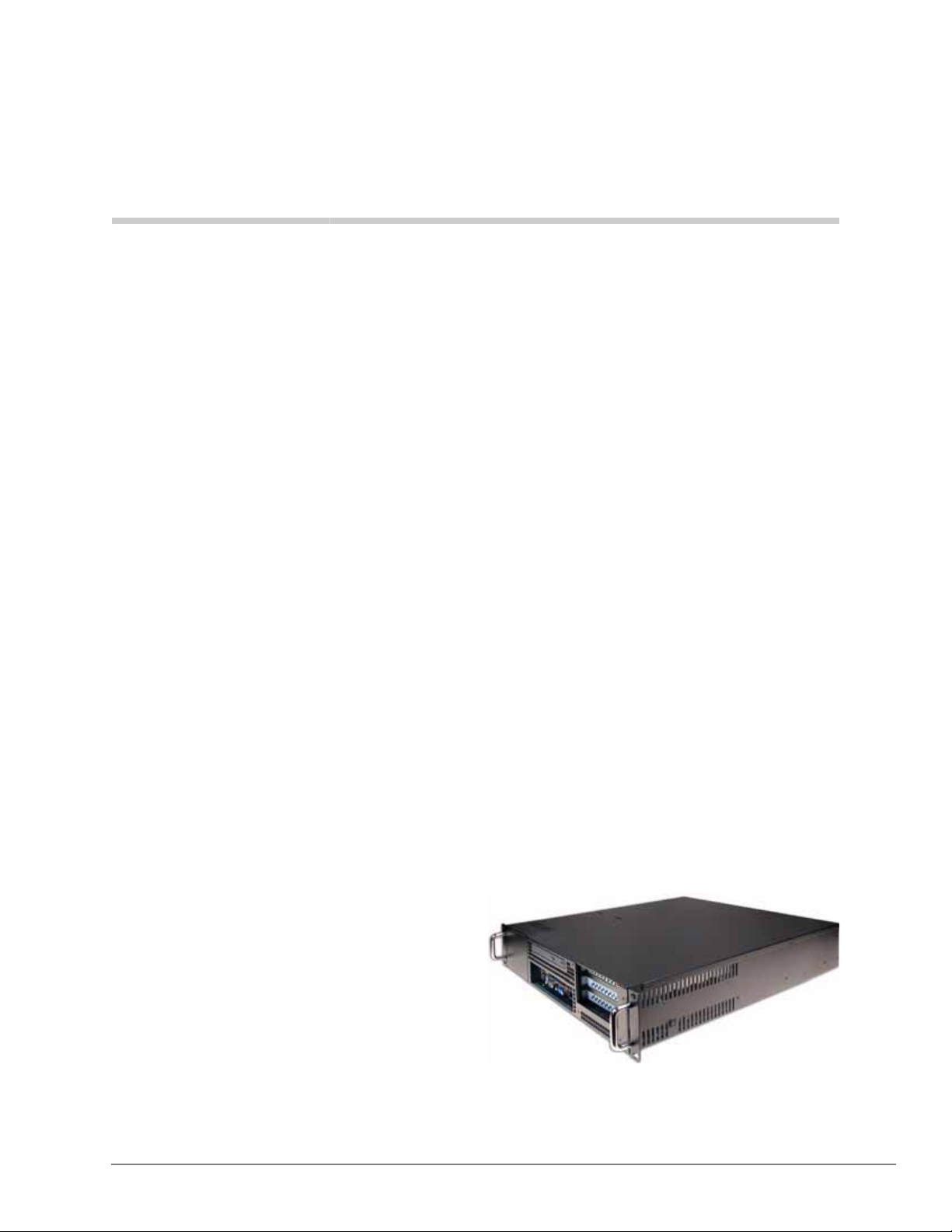
Strata Media Application Server
and Integrated Voice Mail Cards 8
Strata Media Application Server (MAS)
The MAS allows multiple applications to be combined on a single device. Applications include
Auto Attendant, Voice Mail, Fax, Automated Speech Recognition, Text-to-Speech, Unified
Messaging, Interactive Voice Response, Automatic Call Distribution and Reporting, Web browser based Personal and System Administration, W e b-b ased Telephone Applications, FeatureFlex
adaptability tools, and third-party applications.
Because it reduces the need for multiple servers to support each application separately, Strata
Media Application Server dramatically decreases the cost and complexity of deploying multiple
applications.
• The Media Application Server uses Host Media Processing (HMP) technology from Dialogic.
• With HMP the MAS does not require expensive dedicated boards for voice processing
resources. Instead, HMP uses the host CPU for media processing.
• When both ACD and Stratagy ES licensed and running on the same MAS, then HMP does
require specific configurations; up to 16 HMP Voice Mail ports in addition to 16 HMP ACD
announcement ports can be supported.
• If ACD is installed on MAS without Stratagy, up to 32 HMP announcement ports are
available. All port expansion is done with simple software license upgrades.
• If Stratagy is installed on MAS without ACD, up to 32 HMP voice mail ports are available.
The Media Application Server comes in two hardware form factors:
• 2U rackmount platform
• Desktop computer (MicroMAS)
2U Rackmount Platform
The 2U platform (shown right) offers the full
premium of features and applications in a
robust rackmount platform. It is equipped
with a Pentium IV 2.8 Ghz CPU that
supports up to 32 ports of IP voice
connectivity to the Strata CIX. The optional
fax modem boards, required to support fax
features in the 2U MAS, are available in 1, 4,
and 8 port configurations. The 2U MAS can
be equipped with up to two fax modem boards, for a maximum fax modem port capacity of 16.
The 2U MAS platform is also available in, factory equipped, RAID 1 or RAID 5 hard drive storage
configurations.
Strata CIX General Description 04/13 73
Page 96

Strata Media Application Server and Integrated Voice Mail Cards
Strata Media Application Server (MAS)
MicroMAS
For CIX customers that do not require large IP voice
connectivity , yet desire the benefits of a devi ce powering
multiple applications, a smaller, more cost effective
MAS hardware solution is available. Called MicroMAS
(shown right), this platform is a small desktop computer
equipped with all of the applications of a MAS solution
up to a maximum IP voice connectivity of eight ports.
This makes it a perfect multi-application solution for the
Strata CIX40 and CIX100.
The MicroMAS itself comes in two configurations; HMP based and Dialogic hardware based. The
HMP based solution, MicroMAS-H, provides VoIP connectivity to the CIX, whereas the Dialogic
hardware based MicroMAS-D connects to a CIX by means of standard analog port interfaces.
MicroMAS also supports fax applications. The MicroMAS-H can be optionally equipped with two
1 port fax modem boards, connected to the CIX via analog ports, for a maximum capacity of 2
ports of fax.
The MicroMAS-D can be equipped with a maximum of two 4-port D/4PCIU-F Dialogic boards.
Each of the 4 ports of this board can implement a soft fax application, allowing the MicroMAS-D
to support up to 8 ports of voice or fax. If the MicroMAS-D is to support speech recognition
applications, then a 4 port D/4PCIU-S board is required. This board cannot support fax,
consequently fax and ASR applications are mutually exclusive from each other on a MicroMAS-D
platform. MicroMAS-H can support both ASR and fax.
Important! Whenever the MAS is mentioned in the remainder of this chapter, it applies to both
the 2U MAS and MircoMAS, unless specified otherwise.
Standard Software Applications
The Strata Media Application Server comes standard with the following pre-installed applications:
• Stratagy Enterprise Server (ES) Auto Attendant/Voice mail with five Unified Messaging seats.
• eManager Web browser-based unified system administration and maintenance for installation
technicians.
• My Phone Manager Web browser-based personal administration for individual end users and
system administrators.
• Strata Automatic Call Distribution (ACD) application gives call centers the ability to determine
how calls are best distributed to their ACD Agents.
• The Insight family of products are call center management software solutions that can be
configured for businesses served by the Strata Business Telephone Systems and the ACD
application. Insight may be purchased in many configurations to provide management
solutions to both small, informal call centers requiring basic, single supervisor packages to
large call centers requiring sophisticated, networked solutions. Each model is easily upgraded
by entering new license codes which feature additional capabilities.
• TASKE Contact provides a suite of easy-to-use management tools that enable a contact center
supervisor to manage their agents, set and meet service levels and provide vital management
information on call activity . TASKE Contact is a robust management application that's easy to
use and includes ACD Monitor with Replay feature, Reports, WallSign, myTASKE and
Traffic Analyzer. TASKE Contact has several add-on modules to further enhance the
application and includes Contact Desktop Sign, TASKE Enterprise Client and TASKE Work
Force Management Interface.
Note Strata ACD, Insight, and TASKE Contact require licenses. Refer to CIX Quote for
configurations and part numbers.
74 Strata CIX General Description 04/13
Page 97

Strata Media Application Server and
Integrated Voice Mail Cards
Optional Software Applications
The Media Application Server is shipped with all standard and optional application software preloaded. The following optional software modules are also available with additional licensing:
• Stratagy ES ports upgrades up to a maximum of 32 (on 2U MAS platform).
• Stratagy ES Feature Groups (Automated Speech Recognition, Fax, Text-to-Speech, Unified
Messaging, Interactive Voice Response).
• FeatureFlex
• Strata ACD and OAISYS modules (For details, refer to the Strata CIX and CTX Call Center
Solutions General Description).
• Insight or TASKE ACD Reporting (For details, refer to the Strata CIX and CTX Call Center
Solutions General Description).
• Video Communication Solution (VCS)
To activate optional software modules in the Media Application Server, product and service
licenses are purchased and downloaded from FYI using the same process as for current Toshiba
license-controlled products. The Fax Feature Group requires the purchase of fax modem boards
that will be installed in the MAS chassis and connected to the CIX via analog interface circuits
(e.g. BSLU). Fax modem boards are available in 1, 4, and 8 port configurations. MicroMAS-H can
only be equipped with the 1-port fax modem boards.
The pre-loaded software should never need to be re-loaded on the Media Applicatio n Server , but in
the event this becomes necessary, the MAS recovery CD-ROM set can be ordered from Internet
FYI.
Connection to the Strata CIX
The Media Application Server with HMP connects to the CIX using IP connections through a
Network Switch. All of the feature communications and Voice Mail speech paths are carried by
this ethernet connection. The Strata CIX must also be equipped with IP station boards for voice
path assignment.
As described before, MicroMAS-D and the fax modem boards of the 2U MAS and MicroMAS H
require analog ports from the Strata CIX. The fax modem boards come in 1, 4, and 8 port
configurations. Depending the fax port capacity desired, from one to sixteen CIX analog circuits
(e.g. BLSU) may be required.
The monitor, keyboard and mouse are customer supplied options. The MAS can be accessed via
the network by using the Windows® XP Remote Desktop feature.
The CIX MIPU / LIPU / GIPU / GIPH card IP Address must be accessible by the MAS.
The MAS and CIX must be physically installed first. Mount the MAS in the rack. Insert the circuit
cards into the CIX cabinets. Connect the IP cables. When all of the cables are connected, power up
the system and proceed to the MAS configuration and programming.
Strata CIX General Description 04/13 75
Page 98

Strata Media Application Server and Integrated Voice Mail Cards
Preloaded Software
Preloaded Software
The MAS is shipped with the application software loaded. Product and service licenses are
downloaded from FYI. Refer to the Toshiba Strata CIX Programming Manual (Vol. 2).
The pre-loaded software should never need to be loaded. In the event this becomes necessary the
MAS Recovery CD-ROM set, included with the server should be used.
Important! Installation of any software not approved by Toshiba voids the warranty.
Windows XP Firewall Settings
The MAS runs on the Windows XP Professional operating system. Windows XP includes an
Internet Connection Firewall (ICF). When installing the MAS, consider the configuration of the
network and how the MAS will be accessed. Changes to the ICF may be required. Considerations
include:
• Will the MAS be accessed using remote desktop or will a keyboard, monitor and mouse
connected to the MAS be the only direct access?
• Will the MAS be addressable via the internet?
MAS Configuration Requirements
The MAS is a platform for running real-time IP based multimedia applications. It must process
each IP packet of a multimedia stream, each voice packet, within a fixed amount of time, generally
20 ms. It is imperative that the amount of processing required of the MAS in the worst case not
exceed its capacity in terms of processor speed, cache size, or memory size.
To ensure that the capacity of the MAS is not exceeded, two steps must be taken.
• The number of real-time voice channels processed on the MAS must be limited. When licenses
are generated FYI checks what is currently licensed on the MAS, what is being added, and
checks to see that the maximum is not being exceeded. This information is also programmed
into CIX Quote.
• No other applications or windows components should be loaded onto the MAS. Many
applications can, all by themselves, exceed the ability of the MAS to meet its 20 ms response
time requirement, other applications working together can also exceed it.
This document contains information about specific applications and configurations. As the product
and market evolve, we will update this document. Please check back on FYI occasionally for the
latest version of this document.
76 Strata CIX General Description 04/13
Page 99
Strata Media Application Server and
Integrated Voice Mail Cards
Approved Third Party Application Software
The table below shows the only third party application software that should be installed on the
MAS.
Important! Installing any other applications will void the warranty, and tech support will not
provide any support until the MAS has been brought back to a reliable configuration.
Table 15 Third Party Application Software
Application Configuration Notes
PC-cillin™ Internal Security 2005
Symantec’s Norton Anti-Virus™ 2005 Script blocking option must be un-checked.
McAfee® Virusscan® 2005 Ver. 9.0 Script blocking option must be un-checked.
Zoom Modem Driver
Trend Micro and PC-cillin are registered trademarks of Trend Micro Inc.
Norton Anti-Virus is a registered trademark of Symantec Corp.
McAfee and Virusscan are registered trademarks of McAfe e, Inc.
Should not be run in batch mode when running any
other applications.
Zoom™/Modem V.92 USB Mini.
Maximum MAS Configurations
The tables below show the available part numbers for the features that can be licensed to run on the
MAS, and the maximum number of each that can be supported. However, we recommend
checking all configurations through CIX Quote.
The tables below have three columns showing maximum configurations, the first shows the
constraints on a MAS configured with both SES and ACD. The second column shows the
constraints on a system that is configured with only Voice Mail. The third column shows the
constraints of a system that is only configured with ACD.
Note MAS licenses are required for all Strata CIX systems – CIX40, CIX100, CIX200, CIX670,
and CIX1200.
Table 16 Toshiba SES and Feature Flex - Maximum Number of Licenses Shown
Feature License
Alarm Clock Enable LICMAS-FF-ACLK 1 1 0
Auto Speech Recognition Auto Attendant.
Call Monitor Enable LICMAS-FF-CMON 1 1 0
Call Return Enable LICMAS-FF-CRET 1 1 0
LICMASFGASRAA,
LICMASUPASRAA-2
SES and
ACD
88 0
V oice Mail
Only
ACD
Only
Call Screen Enable LICMAS-FF-CSCR 1 1 0
Four Port Upgrade for S trat agy ES on MAS
Note: Four ports per license.
Strata CIX General Description 04/13 77
LICMAS4PORTUPG 4 5 0
Page 100
Strata Media Application Server and Integrated Voice Mail Cards
MAS Configuration Requirements
Table 16 Toshiba SES and Feature Flex - Maximum Number of Licenses Shown (continued)
Two port up grades for Stratagy ES on
MicroMAS-H
Two port up grades for Stratagy ES on
MicroMAS-D
LICMAS-H-2P-UPG 2 4 0
LICMAS-D-2P-UPG 2 4 0
LICMAS-FG-UM,
LICMASUM10SEATS,
One Seat Unified Messaging Upgrade.
LICMASUM25SEATS,
Unlimited Unlimited 0
LICMASUM50SEATS,
LICMASUMUNLIMT
Fax feature license (one per system) LICMAS-FG-FAX 1 1 0
One Number Access Enable LICMAS-FF-ONUM 1 1 0
Text-To-Speech Feature Group. LICMASFGTTSETI 4 8 0
Table 17 ACD - Maximum Number of Licen ses Shown
Feature License
SES and
ACD
Voice Mail
Only
Advanced Partner Program ACD Demo SW - B LICMAS-ACDBR 1 0 0
Advanced Partner Program ACD Demo SW -
H
LICMAS-ACDHQ 1 0 0
ACD
Only
OAISYS Call Router License for Strata ACD LICMAS-CALLRUTR 1 0 1
OAISYS Chat Text Messaging License LICMAS-CHATSEAT 360 0 360
OAISYS Diamond out-of-plan upgrade for
MAS
LICMAS-SUP-OUT 999 0 9 99
OAISYS Diamond support for MAS LICMAS-SUP-OAI 999 0 999
OAISYS IVR Option with Database Assistant LICMAS-ACDIVR 1 0 1
OAISYS Net Phone and chat license for MAS LICMAS-NETSEAT 360 0 360
OAISYS Net Phone server and client LICMAS-NETPH 1 0 1
Strata ACD Basic ACD 20 agent add-on lic LICMAS-BASADD20 17 0 17
Strata ACD Enhanced ACD 20 agent add-on LICMAS-ENADD20 17 0 17
Strata ACD MAS license (10 basic agent, LICMAS-ACDBA10 2 0 2
Strata ACD MAS license (20 basic agent, LICMAS-ACDBA20 1 0 1
Strata ACD MAS license (20 enhanced agent LICMAS-A CDEN20 1 0 1
Strata ACD upgrade to enhanced for MAS, LICMAS-UPGENHD 1 0 1
Strat a ACD upgrade to enhanced for MAS, LICMAS-UPGADD20 17 0 17
VA port license with HMP license LICMAS-ACDVA 15 0 31
78 Strata CIX General Description 04/13
 Loading...