

Page 1
Page 2

Philips Selecon Offices
Philips Selecon - Dallas
10911 Petal Stree t
Dallas, TX 75238
Tel: 214-647-7880
Fax: 214-647-8031
Philips Selecon - New York
267 5th A ve, 4th Floor
New York, NY 10016
Tel: 212-213-8219
Fax: 212-532-2593
Philips Selecon - Asia Limited
Room 6-10, 20/F Delta House 3 On Yiu Street
Shatin, N.T. Hong Kong
Tel: + 852 2757 3033
Fax: + 852 2757 1767
The material in this manual is for information purposes only and is subject to change without notice. Philips
Selecon assumes no responsibility for any errors or omissions which may appear in this manual. For comments and
suggestions regarding corrections and/or updates to this manual, please visit the Philips Selecon web site at
www.seleconlight.com or contact your nearest Philips Selecon office.
El contenido de este manual es solamente para información y está sujeto a cambios sin previo aviso. Philips
Selecon no asume responsabilidad por errores o omisiones que puedan aparecer. Cualquier comentario, sugerencia
o corrección con respecto a este manual, favor de dirijirlo a la oficina de Philips Selecon más cercana.
Der Inhalt dieses Handbuches ist nur für Informationszwecke gedacht, Aenderungen sind vorbehalten. Philips
Selecon uebernimmt keine Verantwortung für Fehler oder Irrtuemer, die in diesem Handbuch auftreten. Für
Bemerkungen und Verbesserungsvorschlaege oder Vorschlaege in Bezug auf Korrekturen und/oder
Aktualisierungen in diesem Handbuch, moechten wir Sie bitten, Kontakt mit der naechsten Philips SeleconNiederlassung aufzunehmen.
Le matériel décrit dans ce manuel est pour information seulement et est sujet à changements sans préavis. La
compagnie Philips Selecon n'assume aucune responsibilité sur toute erreur ou ommission inscrite dans ce manuel.
Pour tous commentaires ou suggestions concernant des corrections et/ou les mises à jour de ce manuel, veuillez s'il
vous plait contacter le bureau de Philips Selecon le plus proche.
Philips Selecon - Auckland
19-21 Kawana Street
Northcote, Auckland 0627
New Zealand
Tel: +64 9 481 0100
Fax: +64 9 481 0101
Philips Selecon - Europe
Marssteden 152
Enschede 7547 TD
The Netherlands
Tel: +31 53 4500424
Fax: +31 53 4500425
Website:
www.seleconlight.com
Note: Information contained in this document may not be duplicated in full or in part by any person without prior written
approval of Philips Selecon. Its sole purpose is to provide the user with conceptual information on the equipment mentioned. The
use of this document for all other purposes is specifically prohibited.
Document Number: 02.9693.0001 A
Version as of: 25 August 2011
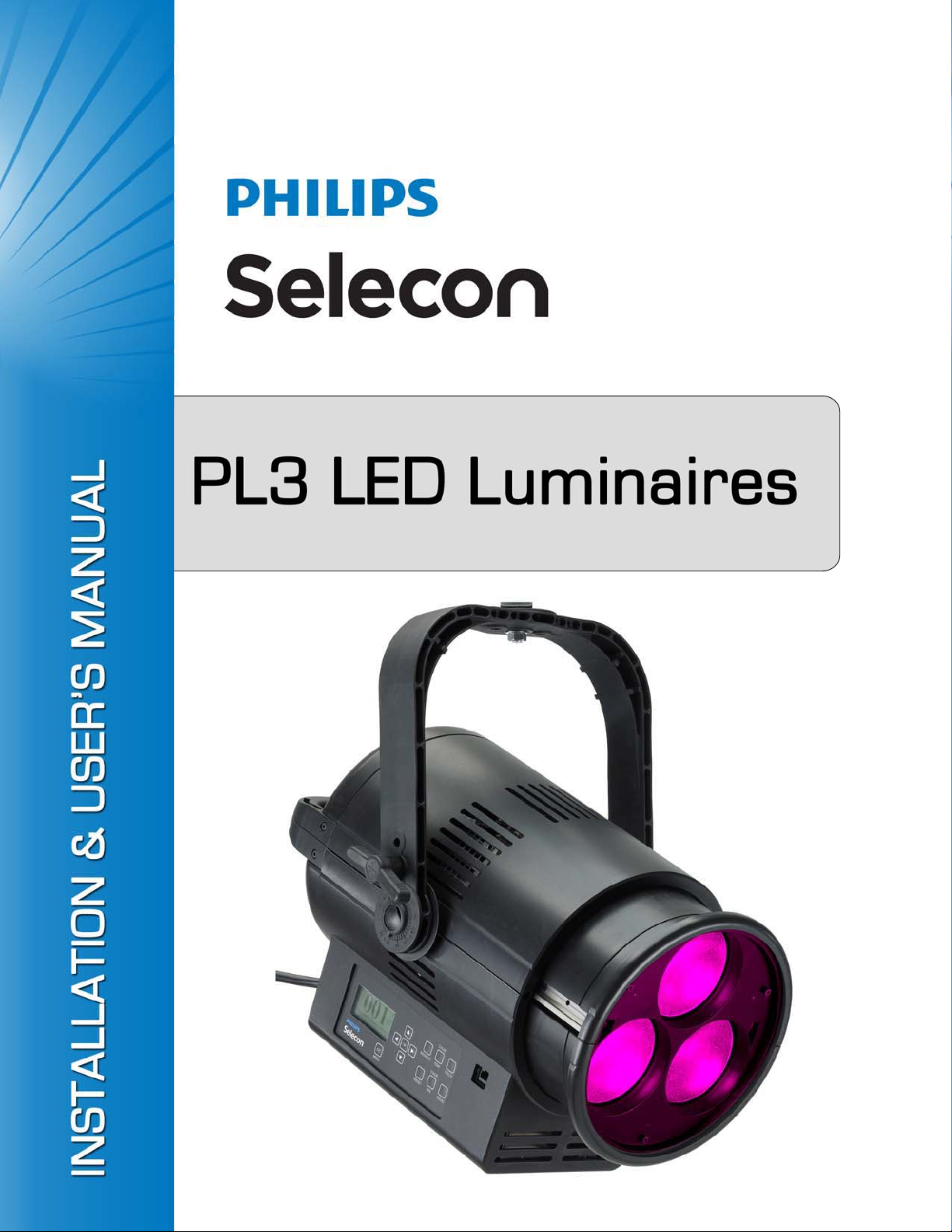
PL3 LED Luminaire Installation & User’s Manual
©2011 Philips Group. All rights reserved.
Page 3
PL3 LED Luminaires
IMPORTANT INFORMATION
Warnings and Notices
When using electrical equipment, basic safety precautions should always be followed including the following:
a. READ AND FOLLOW ALL SAFETY INSTRUCTIONS.
b. For indoor, dry locations use only. Do not use outdoors.
c. Do not mount near gas or electric heaters.
d. Equipment should be mounted in locations and at heights where it will not readily be subjected to
tampering by unauthorized personnel.
e. The use of accessory equipment not recommended by the manufacturer may cause an unsafe
condition.
f. Not for residential use. Do not use this equipment for other than intended use.
g. Refer service to qualified personnel.
SAVE THESE INSTRUCTIONS.
Installation & User’s Manual
WARNING: This equipment is intended for installation in accordance with the National Electric
Code® and local regulations. It is also intended for installation in indoor application s on ly. Before
any electrical work is performed, disconnect power at the circuit breaker or remove the fuse to avoid
shock. It is recommended that a qualified electrician perform this installation.
Additional Resources for DMX512
For more information on installing DMX512 control systems, the following publication is available for purchase
from the United States Institute for Theatre Technology (USITT), "Recommended Practice for DMX512: A Guide
for Users and Installers, 2nd edition" (ISBN: 9780955703522). USITT Contact Information:
USITT
315 South Crouse Avenue, Suite 200
Syracuse, NY 13210-1844
Phone: 800-938-7488 or +1-315-463-6463
www.usitt.org
Philips Selecon Limited Three-Year Warranty
Philips Selecon offers a three-year limited warranty of its luminaires against defects in materials or workmanship
from the date of delivery. A copy of Philips Selecon three-year limited warranty containing specific terms and
conditions can be obtained from the Philips Selecon web site at www.seleconlight.com or by contacting your local
Philips Selecon office.
PL3’s powerful LED engine offers exceptional performance and life. Under normal operating conditions, our LED
engine has a life expectancy in excess of 25,000 hours, however under worst case operating conditions with the
luminaire set to continuous full output it is possible that a small percentage of LED’s may require replacement
sooner. The Philips Selecon three-year limited warranty includes our guarantee against premature failure of the
LED engine.
1
Page 4

Installation & User’s Manual PL3 LED Luminaires
TABLE OF CONTENTS
Philips Selecon Offices......................................................... .................................................................. Inside Front Cover
IMPORTANT INFORMATION
Warnings and Notices..................... ... ......................................................................... ........................................................ 1
Additional Resources for DMX512.................................................................................................................................... 1
Philips Selecon Limited Three-Year Warranty .................................................................................................................. 1
TA BLE OF CONTENTS
PREFACE
About this Manual ...................................................................................................................................................................... 3
ACCESSORIES.......................................................................................................................................................................... 3
PL3 LED LUMINAIRE OVERVIEW
PL3 LED Luminaire Components.............................................................................................................................................. 4
Luminaire Components....................................................................................................................................................... 4
LCD Display / Menu........................................................................................................................................................... 4
INSTALLATION AND SET UP
Power Requirements................................................................................................................................................................... 5
Connecting Power....................................................................................................................................................................... 5
Connecting to the DMX512 Network......................................................................................................................................... 5
Mounting..................................................................................................................................................................................... 6
Pan & Tilt Adjustments .............................................................................................................................................................. 7
OPERA TION AND PROGRAMMING
User Interface.............................................................................................................................................................................. 8
Function Keys.................................................. ........................................................................................................................... 9
Fixture Status Screens................................................................................................................................................................. 9
Menu Options ................. .. .......................................................................... .............................................................................. 10
Menu Structure ..................................................................................... ............................................................................ 10
Security..................................................................................................................................................................................... 12
Passwords.......................................................................................................................................................................... 12
Security Levels ................................................................................................................................................................. 13
Locking Fixture............................................................................................ ..................................................................... 13
Presets....................................................................................................................................................................................... 13
Presets Types .......................... ..................................... ...................................... ............................................................... 13
Editing Preset Names........................................................................................................................................................ 14
Settings...................................................................................................................................................................................... 14
DMX CONTROL
16-Bit Mode.............................................................................................................................................................................. 16
Pan & Tilt DMX Operation Notes.................................................................................................
8-Bit Mode................................................................................................................................................................................ 19
DMX 3-Channel (3-Chan) Mode.............................................................................................................................................. 21
Lighting Console Settings for Preset White ............................................................................................................................. 22
PL3 Luminaire DMX Timing Channel Detail.......................................................................................................................... 22
INFRARED REMOTE CONTROL
Infrared Remote Control Overview .......................................................................................................................................... 28
Infrared Remote Control Features .................................................................................................................................... 28
CLEANING AND CARE
Special Cleaning and Care Instructions .................................................................................................................................... 30
Lens Cleaning ........................................................................................................................................................................... 30
Front Lens (Exterior) ............................... ...................................... ..................................... .............................................. 30
Service and Maintenance....... ...................................... ..................................... ........................................................................ 31
Accessories ............................................................................................................................................................................... 31
TROUBLESHOOTING
Troubleshooting Guide............................................................................................................................................................. 32
TECHNICAL SPECIFICA TIONS
PL3 LED Luminaire Specifications.......................................................................................................................................... 33
PL3 LED Luminaire Dimensions ............................................................................................................................................. 33
................................... 18
2 TABLE OF CONTENTS
Page 5
PL3 LED Luminaires
PREFACE
1. About this Manual
The document provides installation and operation instructions for the following products:
• PL3 LED Luminaires (part number: PL3)
Please read all instructions before installing or using this product. Retain this manual for future reference. Additional
product information and descriptions may be downloaded at www.seleconlight.com.
Note: All PL3 luminaires ship with a "bare-end" 39 inch/1 meter power input cable. Add -GR, -GP, or -GTL to the
part number to have a connector installed. All other accessories sold separately.
Product accessories can be found in "ACCESSORIES".
2. ACCESSORIES
Contact your Authorized Philips Selecon Dealer for price and availability of all accessories for PL3 LED Luminaires.
Additional information can be found on the Philips Selecon web site at www.seleconlight.com.
PL3 LED Luminaire IR Remote
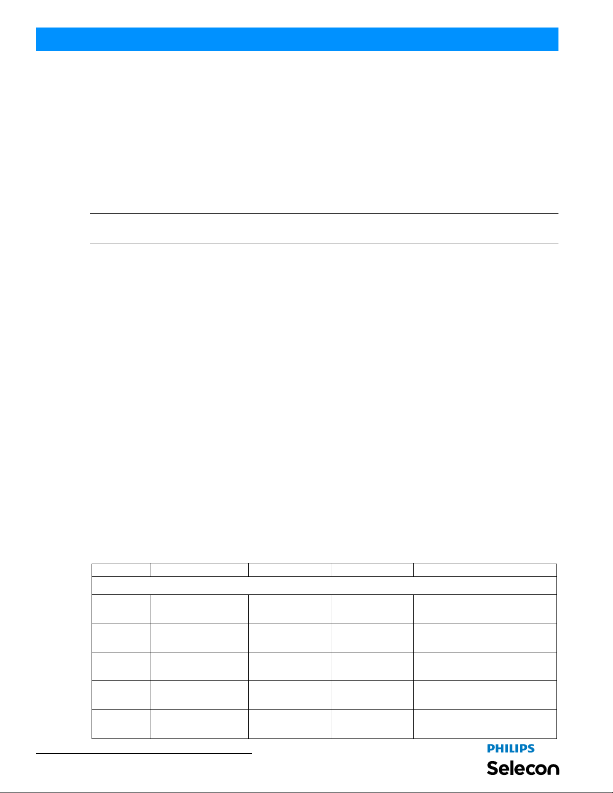
Part Number Description
PL3IRR PL3 LED Luminaire Handheld IR Preset Programmer
Installation & User’s Manual
PL3 LED Luminaire Pan & Tilt Motor Kit / Clamps
Part Number Description
PL3MKIT Pan & Tilt Motor Kit (note, includes all hardware, wiring and truss hook)
SC Selecon Molded Yoke Rated C-Clamp
MC Mega Claw, Black Anodized
Note: Do Not install the PL3 LED Luminaire using C-Clamp (82019 or USCLAMP). This Luminaire requires the
longer bolt utilized in clamps Molded Yoke Rated C-Clamp (SC) or Mega Claw (MC).
PL3 LED Luminaire Barndoors & Holders
Part Number Description
PL3ACH PL3 LED Luminaire Accessory Holder with Frame
20BDSF2020 Barndoor, Black
20BDSF20208 Barndoor, 8 Way, Black
20CFSF2020 Spare Color Frame
PL3 LED Luminaire Connectors
Part Number Description
GR 15A NEMA 5-15P Male Edison Connector
GP 20A, Male Stage Pin Connector
GTL 20A, NEMA L5-20P Male Twist-Lock Connector
PL3 LED Luminaire Spare Power Input Cables
Part Number Description
PL3BE
PC1GP
PC1GTL
PC1GR
PL3 Luminaire AC Power Input Cable (39 inches / 1 meter), Powercon (luminaire AC in) with no
connector (bare end - user to supply connector)
PL3 Luminaire AC Power Input Cable (39 inches / 1 meter), Powercon (luminaire AC in) with Stage
Pin Connector (to power source)
PL3 Luminaire AC Power Input Cable (39 inches / 1 meter), Powercon (luminaire AC in) with
Twistlock Connector (to power source)
PL3 Luminaire AC Power Input Cable (39 inches / 1 meter), Powercon (luminaire AC in) with Edison
Connector (to power source)
About this Manual 3
Page 6
Installation & User’s Manual PL3 LED Luminaires
PL3 LED LUMINAIRE OVERVIEW
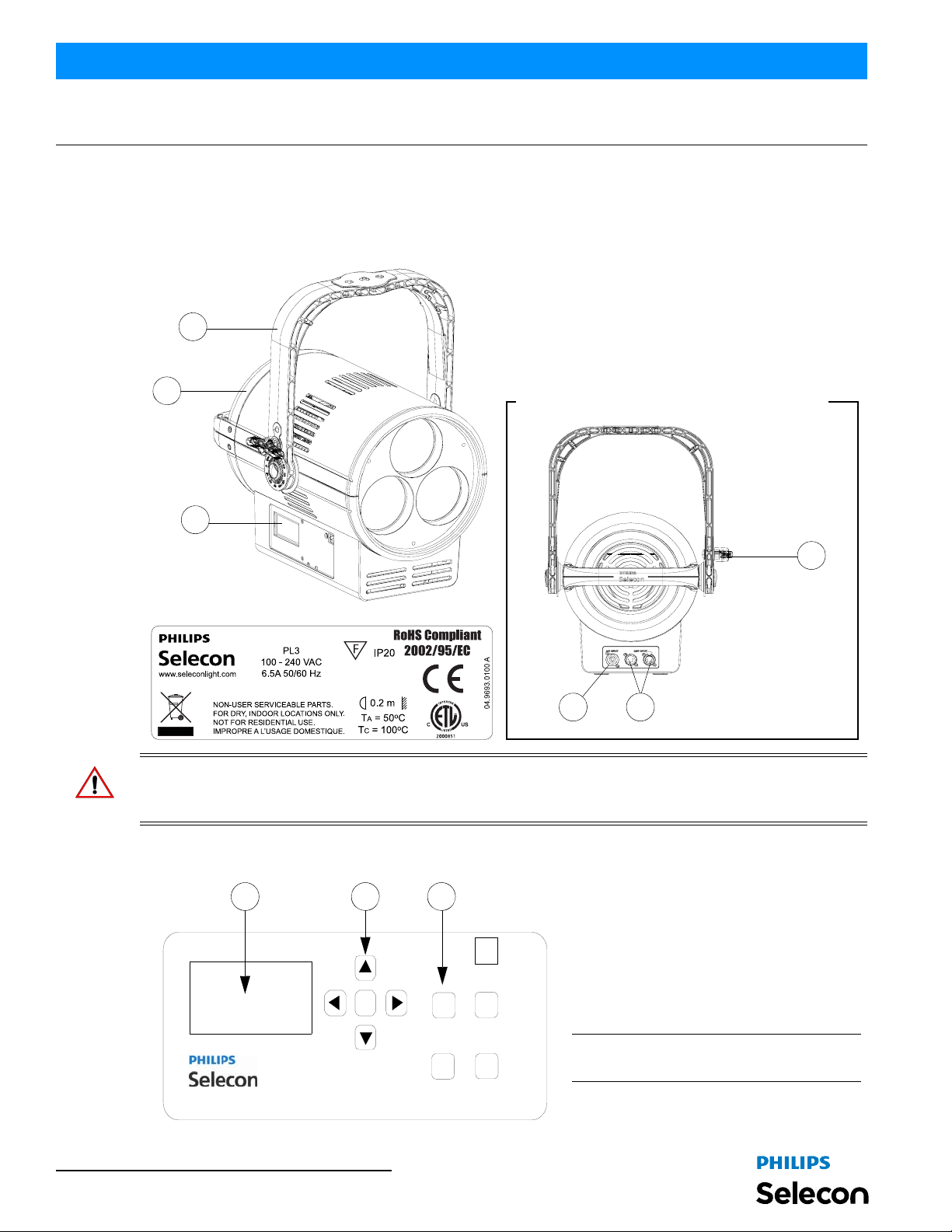
1. PL3 LED Luminaire Components
Luminaire Components
1) LCD Display Menu (see "LCD Display /
Menu" on page 4
2) Lens (Head) Assembly
4
2
3) Tilt Locking Knob
4) Yoke Assembly
5) DMX512 In/Out Connections (see detail)
6) Power Input Connection (PowerCon)
AC Input Power and DMX512 In / Out Connections
for more information)
1
3
Product Label (on yoke assembly)
6
5
WARNING! The PL3 luminaire produces heat. At an ambient temperature of 22o C, the exterior (rear metal grill) of
o
the luminaire reaches 51
C after 5 minutes; 55o C at steady state. In high ambient temperatures, the luminaire
temperature will be higher. Handle with care.
LCD Display / Menu
1
2 3
OK
INTENSITY
ESC
MENU
Pan/Tilt
FOCUS
PRESET
1) LCD Display (Menu System)
2) Menu Navigation Buttons
3) Function (Menu System) Select Push
Buttons / Intensity / Luminaire Focus /
Preset Buttons
Note: For Menu operation and programming
details, refer to "User Interface" on page 8.
4 PL3 LED LUMINAIRE OVERVIEW
Page 7
PL3 LED Luminaires
INSTALLATION AND SET UP
1. Power Requirements
The PL3 LED Luminaire operates on 120 to 240 volts AC (+/- 10%, auto-ranging). The luminaire contains an autoranging power supply. Depending on supply voltage, each luminaire can draw up to 4.60 amps.
2. Connecting Power
If the unit is supplied with an AC input cable (PL3BE), Table 1 describes how to connect power to your PL3 LED
Luminaire. Field wiring of the PL3 LED Luminaire is straight forward. A total of 3 wires/conductors need to be
brought to the unit. For detailed power specifications, see "PL3 LED Luminaire Specifications" on page 33. The
following wiring scheme is required:
Table 1: PL3 LED Luminaire AC Input Connections
Wire Color Purpose
Brown Main / Line (120 to 240VAC)
Blue Neutral
Green/Yellow Ground / Earth
3. Connecting to the DMX512 Network
Installation & User’s Manual
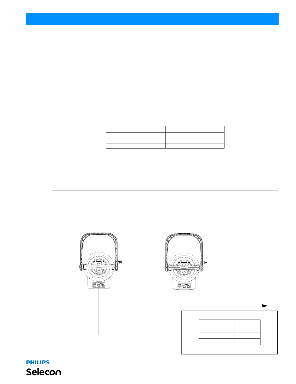
Basic DMX512 installation consists of connecting multiple PL3 LED Luminaires together in "daisy-chai n" fashion.
A cable runs from the control console (or DMX512 control source) to the DMX connector on the first PL3 LED
Luminaire. Another cable runs from the other DMX connector on the first unit to a DMX connector on the next PL3
LED Luminaire (or DMX512 device to be controlled).
Note: For more information on DMX512 networking and systems, refer to "Additional Resources for DMX512" on
page 1. For PL3 LED Luminaire DMX Mapping, refer to "DMX CONTROL" on page 16.
PL3 LED Luminaires
DMX512 (out to the next luminair e or
DMX512 controlled device)
DMX512
(from console or
control device)
DMX512 (out from first
to second luminaire)
DMX512 Connections
DMX512 Signal XLR Pin
Common (Drain) 1
DMX512 - 2
DMX512 + 3
Note: Remaining pins on each connector are not used.
Power Requirements 5
Page 8
Installation & User’s Manual PL3 LED Luminaires
4. Mounting
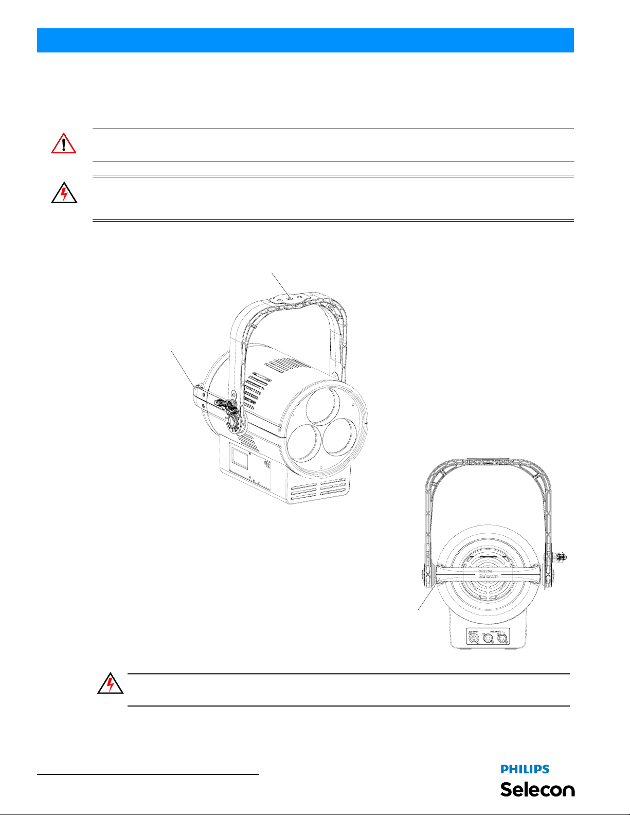
PL3 LED Luminaires offer a plastic monocoque yoke design for mounting by theatrical clamps or hooks (sold
separately).
Note: Do Not install the PL3 LED Luminaire using C-Clamp (82019 or USCLAMP). This Luminaire requires the
longer bolt utilized in clamps Molded Yoke Rated C-Clamp (SC) or Mega Claw (MC).
WARNING! Before attempting any installatio n or service, disconnect all power at power source. T urning of f the
luminaire does not disconnect power. Installation and service should only be performed by trained and qualified
personnel. You must follow local and national codes for fixture installation.
1/2-inch (13 mm) Clamp Mounting Hole. Clamp sold sep arately.
See “PL3 LED Luminaire Pan & Tilt Motor Kit / Clamps” chapter
Luminaire Handle
Rear View
Luminaire Handle
WARNING! Safety cable (integrated into the lumi naire handl e assembly) should be used per local or
national code.
6 INSTALLATION AND SET UP
Page 9
PL3 LED Luminaires
5. Pan & Tilt Adjustments
WARNING! Before adjusting pan or tilt, the luminaire should be mounted per local and national safety codes.
To ad just tilt:
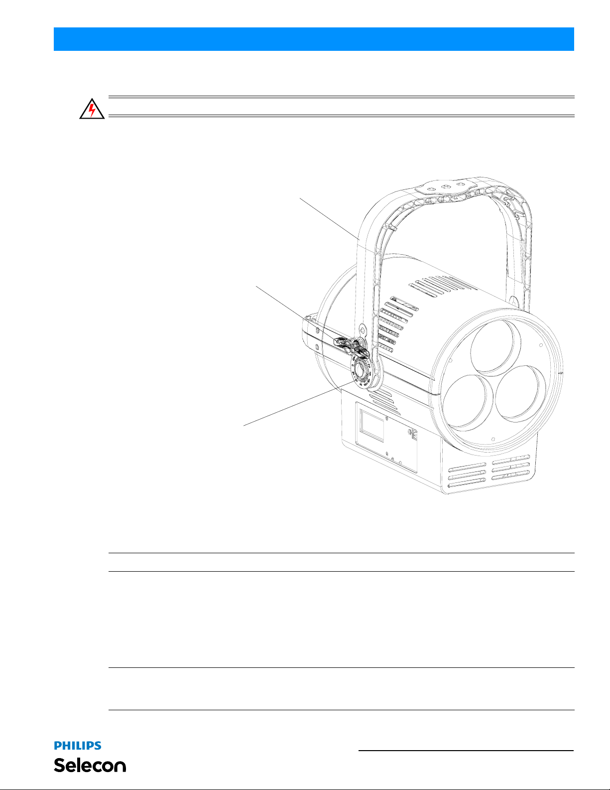
Step 1. Locate yoke lock handle, as illustrated in Figure 1, on side of yoke assembly.
Yoke Lock Handle
Installation & User’s Manual
Yoke Assembly
Luminaire Tilt Indicator
Figure 1: PL3 Yoke Lock Handle
Step 2. Loosen yoke lock handle by hand.
Step 3. Position luminaire tilt (up or down) as desired.
Note: Each luminaire contains a tilt indicator near the yoke lock handle to allow setting of luminaires at same angle.
Step 4. Hand-tighten, but do not over tighten, yoke lock handle.
To adjust pan:
Step 1. Loosen, but do not remove, nut securing clamp to yoke assembly.
Step 2. Position luminaire pan (left or right) as desired.
Step 3. Retighten clamp nut.
Note: If Pan and Tilt Motors (PL3MKIT, sold separately) are installed, see "Focus Button (also for manual Pan &
Tilt control*)" on page 9 for manual control operation or "DMX CONTROL" on page 16 for DMX512 control
parameters.
Pan & Tilt Adjustments 7
Page 10
Installation & User’s Manual PL3 LED Luminaires
OPERATION AND PROGRAMMING
1. User Interface
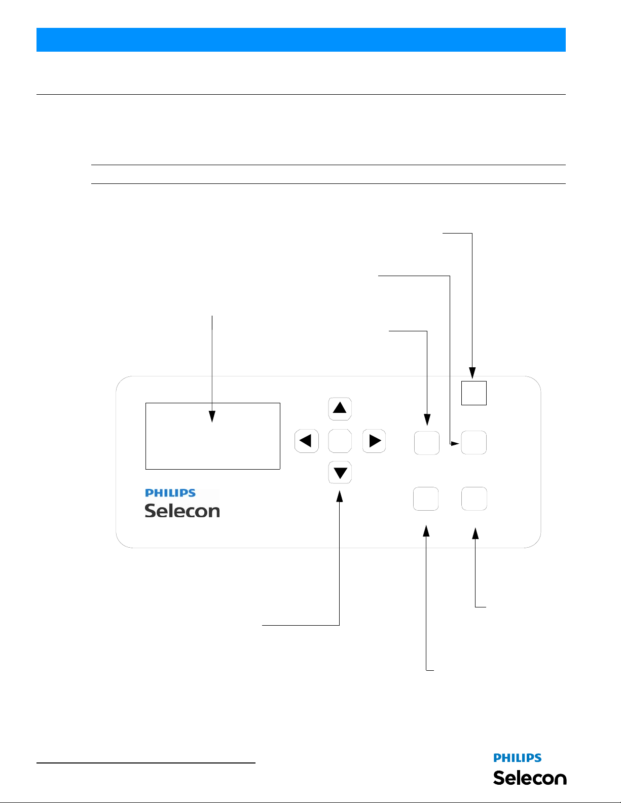
The PL3 LED Luminaire’s LCD Display and Menu System provides local control for accessing all the fixture’s status
information, menu options, and settings.
Note: If there are multiple luminaires in a system, changes would need to be made at each LCD Menu as desired.
Upon power up, the LCD will display the main screen showing the product type/name. If DMX is enabled, the
programmed address will appear after power up.
Pan/Tilt Control Port -
(For use with PL3MKIT
- sold separately)
LCD Display Displays all menu parameters and
option settings. Also displays DMX512
address (DMX models only).
Focus Button Allows adjustment of the
luminaire’s lens zoom.
Intensity Button Allows the customization of
current intensity (light output).
OK
INTENSITY
MENU
Pan/Tilt
FOCUS
ESC
PRESET
Up/Down/Left/Right Arrow Buttons Navigates menu system and used for
selecting and setting options.
OK (Enter) Button Accesses details, activates
a field, or enters a setting
depending on the current menu item.
8 OPERATION AND PROGRAMMING
PRESET Button Allows the recall of
stored presets.
Menu / Escape Button Enters menu options. Navigates
(backs up) one menu level.
Figure 2: LCD Display and Menu System
Page 11

PL3 LED Luminaires
2. Function Keys
These keys provide single touch access to commonly changed parameters of the fixture.
Intensity Button
Once pressed the [UP ARROW] or [DOWN ARROW] keys can be used to change the Intensity level of the Fixture's
output. Press the [LEFT ARROW] or [RIGHT ARROW] keys to scroll between the primary colors to change their
level. Press [OK] to save, or press [ESC] to Cancel changes; and exit.
Preset Button
Once pressed a list of available Presets is displayed, use the [UP ARROW] or [DOWN ARROW] keys to scroll to the
desired Preset. The output changes to the levels stored in the Preset, as you scroll. Press [OK] to Exit and save, or
press [ESC] to Cancel selection; and exit screen.
Focus Button (also for manual Pan & Tilt control*)
Note: * The Focus Button is also used to access manual control of Pan & Tilt operation (requires installation of
PL3MKIT pan/Tilt Motor Kit - sold separately).
For manual Focus or Pan / Tilt control:
Step 1. At luminaire menu panel, press FOCUS button. Zoom Screen appears.
Step 2. Use [UP ARROW] and [DOWN ARROW] keys to switch between ZOOM, PAN, or TILT screens.
Step 3. Use [LEFT ARROW] or [RIGHT ARROW] keys to control ZOOM, PAN, or TILT setting s .
Step 4. Press [OK] when adjustment is complete to exit screen.
Installation & User’s Manual
Note: For DMX512 Control of Zoom (Beam) or Pan / Tilt operation, see "DMX CONTROL" on page 16.
3. Fixture Status Screens
To navigate the Fixture Status Screens:
Press [LEFT ARROW] or [RIGHT ARROW] keys to scroll between the available Status Screens (Note: depending
on scrolling direction Screens may appear in reverse order).
a. DMX Address (Note: If fixture is UNLOCKED, hit [OK] to change DMX address; Screen is not
displayed if DMX id disabled)
b. Fixture Hours (Displays fixture, outputting light, ON time)
c. Fixture Power (Displays Present power to the LEDs (in watts))
d. Fixture Status (Displays, Current Preset, Temperature Status, LED Status, and Fan Status)
e. Splash Screen (Displays Serial Number, Software version, and Status Icons)
Press [ESC] at anytime to access the Menu Options
Note: The default Status Screen is DMX Address, if DMX is Enabled; otherwise the Splash Screen is the Default.
T o make one of the other screens the Default Screen, scroll to that screen and press [OK], a "tack" icon will appear to
the right of the Screen's Name, at the top of the screen. Press [OK] again to remove "tack" and return to default
operation.
Function Keys 9
Page 12
Installation & User’s Manual PL3 LED Luminaires
4. Menu Options
The menu provides access to numerous Screens to control the Fixtures operation and configuration.
• Press [MENU], while at one of the Status Screens to display the Menu List.
• Use the [UP ARROW] and [DOWN ARROW] keys to select the Menu option, then press [OK] to go to that sub
screen.
• Press [ESC] to close the Menu without making a selection.
• Use the navigation keys to view and change in formation on the Sub Screen(s). Use [OK], or the appropriate
"screen button", to save any changes; use [ESC], or the appropriate "screen button", to cancel changes.
Note: Depending on the security settings, certain menu items may be password protected. You must enter the
PassPIN in order to access these items. Locked items will have a "Key" icon displayed next to them.
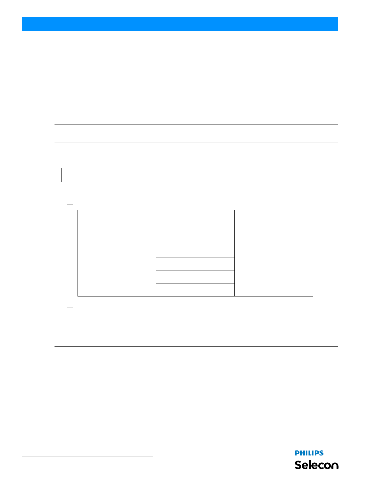
Menu Structure
MAIN MENU
Save as Preset
Sub Menu Options Comments
Users can:
• Save the current settings (look) to
a specific recallable Preset in the
fixture’s memory.
• Edit the levels (values) for Red,
Green, Blue, White, and Intensity
values (in percent%) by using the
arrow buttons. Once the values
are adjusted, the preset is saved
as desired.
*Only intensities may be stored on
White Color Temperature presets.
RGBW in these presets cannot be
edited or changed.
Select Preset to Save - (Option)
Scrolls and sets current user-defined
color mix to various recallable presets
in the fixture using arrow buttons.
Note: T o edit a current (set) preset,
see Edit Presets.
Off
Scratch Pad
Warm White*
Cool White*
Day Light*
Preset X (5 through 31)
Continued next page
Note: See "To navigate the Fixture Status Screens:" on page 9 to learn how to access menus. To save changes, hit
[OK]. Press [ESC] to cancel any changes you made.
10 OPERATION AND PROGRAMMING
Page 13
PL3 LED Luminaires
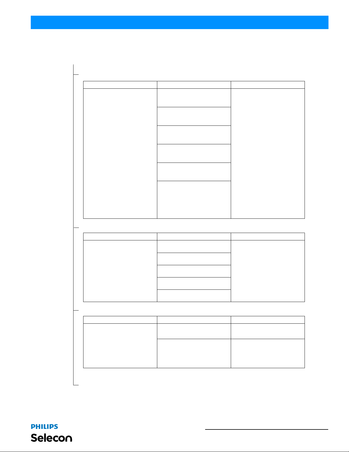
Menu Structure (continued)
Continued from previous page
Edit a Preset
Sub Menu Options Comments
Users can:
Select Preset to Edit - (Option)
Selects a current preset and outputs
the preset, so preset can be edited.
Note: To save a specific look of the
fixture, see Save Presets.
Off
Scratch Pad
Warm White*
Cool White*
Day Light*
Preset X (5 through 31)**
• Edit the current settings (look) to a
specific recallable Preset in the fixture’s memory.
• Edit the values for Red, Green,
Blue, White, and Intensity values
(in percent%) by using the arrow
buttons.
• Once the values are adjusted, the
"Save Preset" menu option
appears to save the edits.
NOTES:
*Only intensities may be stored on
White Color Temperature presets.
RGBW in these presets cannot be
edited or changed.
**If a Calibrated Preset's Color Mix is
changed (5 thru 25), an asterisk '*' is
appended to the end of the name to
indicate that it has been modified.
This only happens if the name
matches the original calibrated name,
stored in EEPROM. This does not
happen if the Intensity is changed,
only the color mix.
Installation & User’s Manual
Color Mix
Sub Menu Options Comments
Red
Users can:
• Edit Red, Green, Blue, White, and
Intensity values (in percent%) by
using the arrow buttons.
• Once the values are adjusted,
press [OK] to save the edits.
Select Color or Intensity to Adjust -
(Option)
Green
Blue
White
Intensity
Fan Control
Sub Menu Options Comments
Highlight "Max" button and hit [OK]
button on menu. Sets the maximum
speed of the fan.
Level sets the fan to a const ant spee d
(will not vary). Adjust level (on fan
speed level bar) using Left and Right
arrow buttons, highlight "Level" button
in menu, and hit [OK] on menu to use
user-defined level.
Select and Set Fan Speed - (Option)
Note, hit Cancel to cancel any
changes you made.
Continued next page
Max
Level
Menu Options 11
Page 14
Installation & User’s Manual PL3 LED Luminaires
Menu Structure (continued)
Continued from previous page
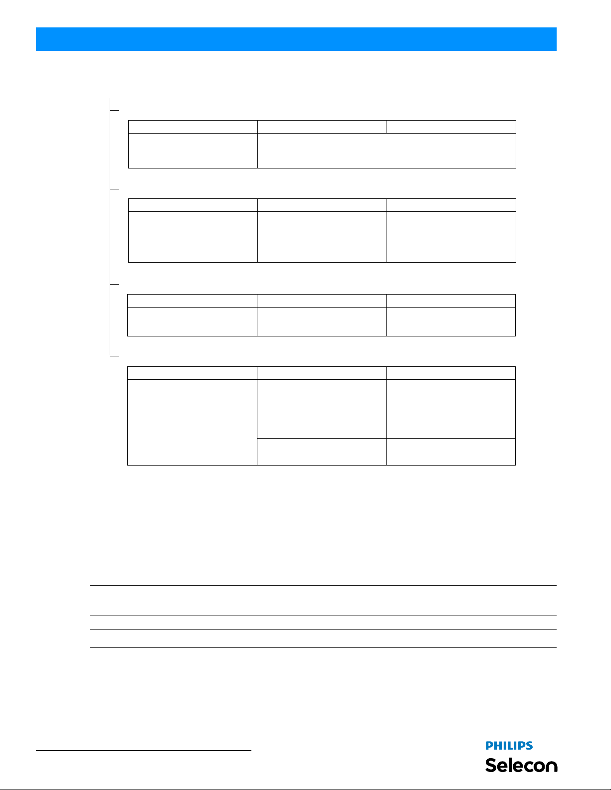
Settings
Sub Menu Options Comments
SETTINGS - (Option)
Scrolls and sets the various fixture
settings using arrow buttons.
Lock Fixture
Sub Menu Options Comments
LOCK - Are you sure? Yes (to Lock Fixture) / No
Enter Password
Sub Menu Options Comments
Enter Pass PIN Enter four-digit password
See "Settings" on page14 for details.
Use arrow buttons to make selection.
Press [OK] to accept. Note, a
password must be established (set) in
order to lock a fixture. Locking the
fixture will disable access to changing
menu settings.
For details, refer to "Security" on
page 12.
LED Status
Sub Menu Options Comments
Displays LED’s current status (in
LED Status Information
Scrolls through the various levels
using arrow buttons as indicated on
menu screen. Depending on the
arrow button pressed, the screens
may appear in a different order that
shown in "Options".
LED 1
Levels
percentage%) of Intensity, Red,
Green, Blue, and White elements of
the LED). Also displays current color
temperature (i.e., WARM WHITE),
Fan Speed, operational LED junction
temperature, power settings.
Displays DMX levels for each LED
element (Red, Green, Blue, and
White) and total power.
5. Security
Unwanted changes to the Fixture's Configuration or Setting can be controlled by setting a security level, or Locking
the Fixture. Three levels of security are available in addition to completely Locking the Fixture.
PL3 luminaires are shipped with default passwords. Users may set their own password (four-digit number). When
setting a password, write it down and keep it in a secure location. Note, Philips Selecon does not have records of
passwords established by users or owners.
Note: Contact Philips Selecon technical support if a unit is locked and the password is lost for instructions on how to
reset luminaire.
Note: If the Fixture is locked when it is powered down the fixture will remain in the locked state when powered up.
Passwords
Establishing or Changing Passwords
Step 1. At a Status Screen, press [MENU] and scroll to "Settings", press [OK].
Step 2. Go to the Security section.
12 OPERATION AND PROGRAMMING
Page 15
PL3 LED Luminaires
Step 3. Select a Level to change ( Level 1 PIN / Level 2 PIN / Level 3 PIN).
Step 4. Press [OK] to edit using the [UP ARROW], [DOWN ARROW], [LEFT ARROW] or [RIGHT ARROW]
keys to enter a four-digit password (using 0 to 9).
Step 5. Press [OK] to save changes. If you hit [ESC] (Escape) password will not be stored and process must be
repeated.
Step 6. Password is set.
Note: The current security level is displayed next to the Security heading. Only Passwords at, or below, th at level
will be displayed for modification. The level can be changed by entering a higher level Password on the "Enter
PassPIN line directly below the Security heading, like Step 4 above.
Security Levels
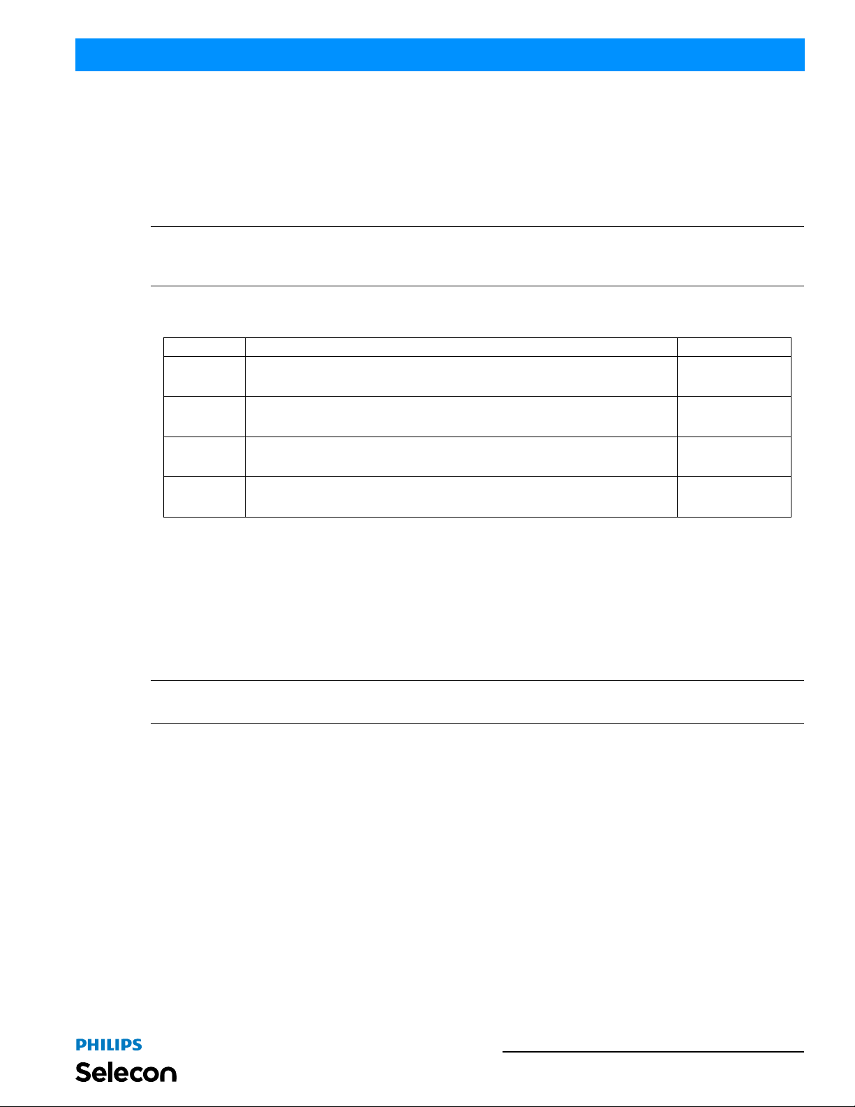
Security Level Description Default PassPIN
0
Installation & User’s Manual
System is locked; the only key that is active is the Menu/ESC Key. When this key is pressed a
PassPIN is requested.
Not Applicable
1
2 Editing and Saving of Presets is added to Level 1 functionality. 2222
3 Operationally the same as level 2, however all settings are available on the Settings screen. 3333
All keys are Active.
You can select any Preset, and change Intensity, set DMX Address.
Locking Fixture
To lock the fixture:
Step 1. At a Status Screen, press [MENU] and scroll to "Lock Fixture".
Step 2. Press [OK].
Step 3. Use [LEFT ARROW] or [RIGHT ARROW] keys to highlight "YES" ", press [OK].
Step 4. Fixture is now locked.
Note: When the Fixture is Locked only the [ESC]/[MENU] key is functional. Pressing this key will display a request
for a password. When a valid password is entered the fixture is unlocked to the security level of the entered password.
6. Presets
Presets are Color Mixes that are stored in the Fixture, they can be recalled to reproduce a specific output from the
fixture. Presets are made up of a Color Mix; Red, Green, Blue, and White. They also have Intensity associated with
them.
Presets can be recalled via the User interface or by a DMX channel, when under DMX control. The Preset’s Intensity
is applied if the User Interface is used; if DMX, the DMX Intensity channel is used for Intensity.
1111
Presets Types
Presets are classified as Locked, Protected, or User. The type of preset determines what aspects of the Preset can be
modified.
Locked
Locked Presets are factory Calibrated, and their Color Mix cannot be changed by the user. Their Intensity can be
changed. Three Presets (2-4), "Warm White', "Cool White", and "Day Light", are Locked.
Presets 13
Page 16
Installation & User’s Manual PL3 LED Luminaires
Preset 0, the "off" preset is also Locked to the OFF value.
Protected
Protected Presets are also Factory Calibrated, and by default are Protected from changes to their Color Mix. Their
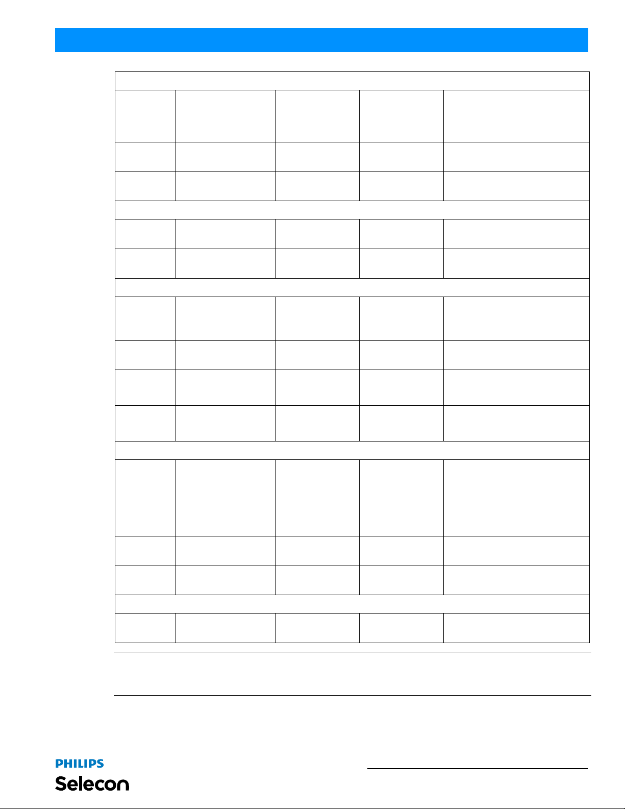
Intensity can be changed. Protected Presets are Presets 5-25. They can be Un-Protected by setting "Protected" to
"No"; see section on Settings. If Un-Protected these presets function like User Presets.
The Factory Calibrated values for the protected presets can be re-loaded to the original factory calibration settings by
setting "Load Factory" to "Yes" "; see section on Settings.
User
User Presets can have their Color Mix and Intensity changed without restriction.
Note: If the Color Mix of a Factory Calibrated Preset is changed, by turning protection Off, an '*' is appended to the
end of the Preset's Name to indicate that the Calibrated values have been changed.
Editing Preset Names
On the Edit Preset screen, the option is available to edit the name of a preset, via Screen button. However, the names
of Presets 0-4 cannot be edited.
Use the [LEFT ARROW] and [RIGHT ARROW] keys to select the character to be changed and use the [UP
ARROW] and [DOWN ARROW] keys to change that character. The Character Scroll order is A-Z, space, 0-9. If you
are scrolling up the Alpha character displays as Upper Case; if you are scrolling down the Alpha character displays as
Lower Case. Stop on the character you want, ignoring case, then press the opposite [UP ARROW] or [DOWN
ARROW] key if you want to change the case. [OK] to save changes, [ESC] to cancel changes.
7. Settings
The following Parameters can be changed on the Settings Screen.
The first column "Security Level" is the minimum security level you have to be at before the l ine is displayed for
editing in the Settings screen.
To edit a value on the Setting Screen, use the [UP ARROW] or [DOWN ARROW] keys to move the hi ghligh t to the
settings value you wish to change. Press [OK] to begin editing that value. Use the [UP ARROW], [DOWN
ARROW], [LEFT ARROW] or [RIGHT ARROW] keys to make changes to the value. Press [OK] when complete to
save changes, or [ESC] to cancel changes to that value.
When done making changes on the Settings Screen press [ESC] to re-boot fixture and implement changes. Fixture
will not re-boot if nothing was changed.
Security Level Parameter Values Default Description
Security
1
3 Level 1 PIN 4-Digits (0 to 9) 1111 Sets Level 1 PassPIN
3 Level 2 PIN 4-Digits (0 to 9) 2222 Sets Level 2 PassPIN
Enter
PassPIN
4-Digits (0 to 9) ****
There are 4 levels of security, this allows
you to change the level while in the
Settings Screen.
3 Level 3 PIN 4-Digits (0 to 9) 3333 Sets Level 3 PassPIN
3 Power-Up 1 - 3 or Locked 3
14 OPERATION AND PROGRAMMING
Security Level after Power-Up, if not
Locked (Level 0)
Page 17
PL3 LED Luminaires
General
1 Power-Up
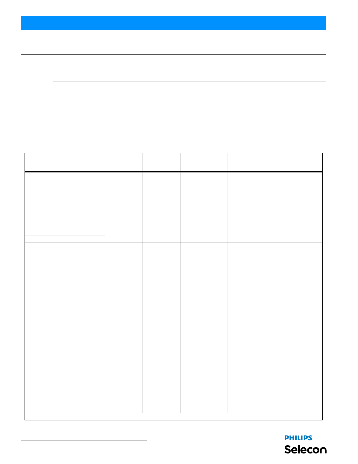
3 IR Enabled No, Yes Yes Turns IR/Laser detection On/Off
3 Reset Hours No, Yes No Resets luminaire’s operational hours.
Presets
3 Protected No, 5 - 25 Yes
3 Load Factory No, Yes No
DMX
3 DMX Enabled
1 Address 001 to 512 001
2 Map 8-bit, 16-bit, or 3-Chan 16-bit
2 When no DMX
Fan
3 Normal / Quiet Normal or Quiet Quiet
Off, Scratch Pad,
Warm White, Cool
White, Day Light,
Preset30, Preset31,
Last Set
No, Yes, or Wire less (if
equipped)
Off, Hold, Hold 8hr (8
hours), or Power-Up
Cool White
Yes
Hold
Installation & User’s Manual
When the Fixture Powers-Up what does it
output. Scratch Pad is an automatically
saved Preset. Last Set is the last thing
coming out of the fixture, this could be
Warm White with the intensity changed
from that of the Preset.
Determines if the factory Calibrated
Presets' Color Mix is protected from
changes.
Reload Factory Calibrated Presets,
Intensity changes will also be reloaded.
Enables or disabled DMX communication
through the luminaires DMX512 ports.
Sets the DMX feature to Wireless DMX (if
wireless DMX option is installed - sold
separately).
DMX512 address. Note, it can be set if
displayed.
Defines size/precision of DMX map. Color
Mixing/Intensity in 16-bit provides higher
resolution for precision control. 3-Chan
provides minimal channel usage.
If DMX is detected and then goes away,
this defines what will happen to the output.
At end of 8Hr hold Fixture goes to PowerUp setting.
NormalNormal - (Normal Mode) Normal
Mode Provides higher cooling margin for
thermally challenging applications.
Recommended for full power (RGBW @
100%) applications with large and
numerous changes in power. Quiet (Quiet Mode) Quite Mode is similar to
Normal mode, but it controls fan tightly to
reduce fan noise.
3 Max% 0 to 100% 100 Sets the maximum fan speed
3 Min% 0 to 100% 1 Sets the minimum fan speed
Display
3 Flip Display No, Yes No Flips (inverts) Display and Keypad Arrows.
Note: To Exit the Settings screen, use the [ESC] key. [ESC] and [OK] can be used to cancel or save changes to an
individual parameter. However, once a parameter has been accepted, by pressing [OK] that change cannot be undone/
canceled by pressing the [ESC] key.
Settings 15
Page 18
Installation & User’s Manual PL3 LED Luminaires
DMX CONTROL
This section contains information for operating the luminaire using DMX control in 16-Bit, 8-Bit, or 3-Channel (3Chan) modes. For Menu options and detailed information, see "Settings" on page 14.
Note: These tables assume a DMX start address of 1. When a different starting address is used, this address becomes
channel 1 function and other functions follow in sequence.
1. 16-Bit Mode
Table 2 provides DMX channel mapp ing of all DMX5 12 control values when the PL3 LED Luminaire is in 16-bit
DMX512 mode (as set by the luminaire’s menu system).
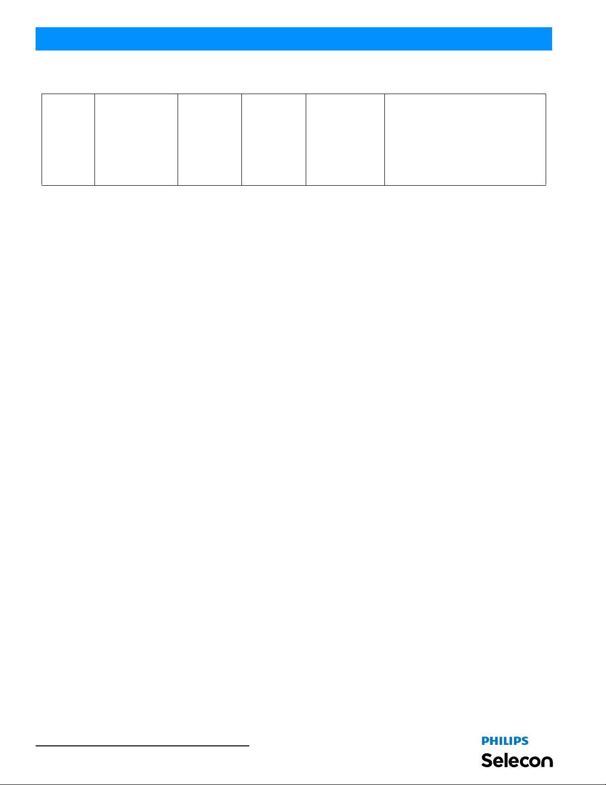
Table 2: PL3 Luminaire DMX Channel Mapping (16-Bit Mode)
DMX
Channel
1 Intensity - High
2 Intensity - Low
3 Red - High Byte
4 Red - Low Byte
5 Green - High Byte
6 Green - Low Byte
7 Blue - High Byte
8 Blue - Low Byte
9 White - High Byte
10 White - Low Byte
11
12 Not used (for future use)
Parameter Range DMX Range%
Preset Color Selection
Notes:
• Color Presets 5
through 25 are calibrated factory colors and can be
reloaded if needed
through the fixture’s
menu system.
• These colors have
been matched to
precise X and Y
coordinates at the
center of the beam
at wide angle, we
have given you the
ability to adjust
these colors as
your personal perception may vary.
Default - recommended console
default values
0 - 65535 0 - 100% 0 16-bit control for Intensity of LED settings.
0 - 65535 0 - 100% 0 16-bit control of Red LEDs from 0 to full.
0 - 65535 0 - 100% 0 16-bit control of Green LEDs from 0 to full.
0 - 65535 0 - 100% 0 16-bit control of Blue LEDs from 0 to full.
0 - 65535 0 - 100% 0 16-bit control of White LEDs from 0 to fu ll.
0 - 255 0 - 100% 0
Description
Used to access presets stored in fixture
firmware, such as CCT presets, defined gel
presets, and more.
No Preset Activated = DMX 0 - 3
Color Preset 0 (Off) = DMX 4 - 7
Color Preset 1 (Scratch Pad) = DMX 8 - 11
Color Preset 2 (Warm White) = DMX 12 - 15
Color Preset 3 (Cool White) = DMX 16 - 19
Color Preset 4 (Daylight) = DMX 20 - 23
Color Preset 5 (Arc White) = DMX 24 - 27
Color Preset 6 (Red) = DMX 28 - 31
Color Preset 7 (Yellow) = DMX 32 - 35
Color Preset 8 (Daylight Blue) = DMX 36 - 39
Color Preset 9 (Magenta) = DMX 40 - 43
Color Preset 10 (Kelly Green) = DMX 44 - 47
Color Preset 11 (Medium Amber) = DMX 48 - 51
Color Preset 12 (Lavender) = DMX 52 - 55
Color Preset 13 (Blue) = DMX 56 - 59
Color Preset 14 (Light Pink) = DMX 60 - 63
Color Preset 15 (Green) = DMX 64 - 67
Color Preset 16 (Pink) = DMX 68 - 71
Color Preset 17 (Amber White) = DMX 72 - 75
Color Preset 18 (Dark Fuchsia) = DMX 76 - 79
Color Preset 19 (Light Amber) = DMX 80 - 83
Color Preset 20 (Steel Blue) = DMX 84 - 87
Color Preset 21 (Lt. Green/Blue) = DMX 88 - 91
Color Preset 22 (Orange) = DMX 92 - 95
Color Preset 23 (Medium Pink) = DMX 96 - 99
Color Preset 24 (Cyan) = DMX 100 - 103
Color Preset 25 (Purple) = DMX 104 - 107
Color Preset 26 (Custom) = DMX 108 - 111
Color Preset 27 (Custom) = DMX 112 -115
Color Preset 28 (Custom) = DMX 116 - 119
Color Preset 29 (Custom) = DMX 120 - 123
Color Preset 30 (Custom) = DMX 124 - 127
Color Preset 31 (Custom) = DMX 128 - 131
16 DMX CONTROL
- Continued next page -
Page 19
PL3 LED Luminaires
Table 2: PL3 Luminaire DMX Channel Mapping (16-Bit Mode)
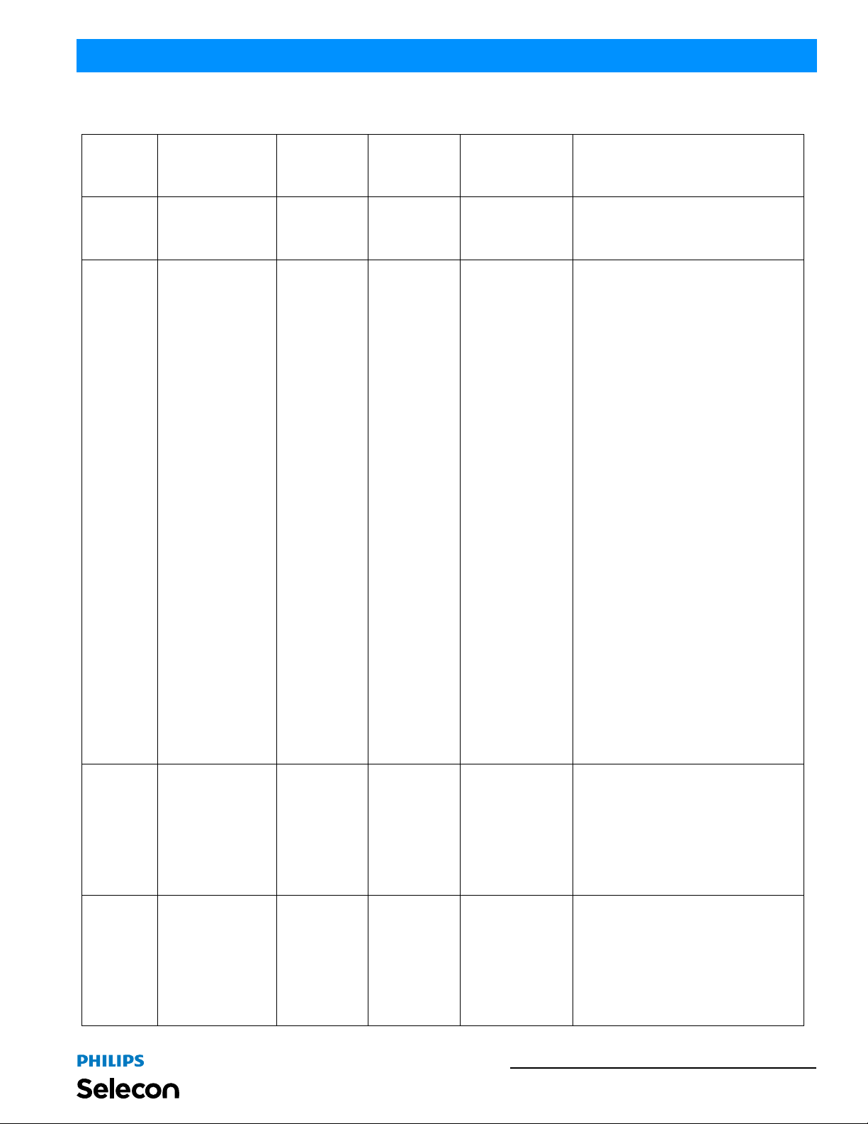
13 Intensity Time 0 - 255 0 - 100% 255
14 Color Time 0 - 255 0 - 100% 255
15 Control 0 - 255 0 - 100% 0
16 Beam 0 - 255 0 - 100%
Pan
17
(See "Pan & Tilt DMX
Operation Notes" on
page 18 for more
information).
0 - 255 0 - 100%
- Continued next page -
DMX 127 (50%,
Motor Stop)
DMX 127 (50%,
Motor Stop)
Installation & User’s Manual
Allows for luminaire timing of intensity. Profile
should default to DMX 255 for smoothest
console fade times. Refer to "PL3 Luminaire
DMX Timing Channel Detail" on page22 for
more information on timing values.
Allows for luminaire timing of LEDs. Profile
should default to DMX 255 for smoothest
console fade times.Refer to "PL3 Luminaire DMX
Timing Channel Detail" on page22 for more
information on timing values.
Used to set different modes, parameters, and
functions of the luminaire. Set control channel
value for desired action. Hold value for at least 3
seconds. Set control channel value to 0 without
any scaling.
Default Setting on Console = DMX 0
Display On/Off = DMX 3 - 4
Reset All to Defaults = DMX 5 - 7
Quiet Mode = DMX 11 - 13
Normal Mode = DMX 14 - 15
Preset 1 Store = DMX 20 - 21
Preset 2 Store (Intensity Only) = DMX 22 - 23
Preset 3 Store (Intensity Only) = DMX 24 - 25
Preset 4 Store (Intensity Only) = DMX 26 - 27
Preset 5 Store = DMX 28 - 29
Preset 6 Store = DMX 30 - 31
Preset 7 Store = DMX 32 - 33
Preset 8 Store = DMX 34 - 35
Preset 9 Store = DMX 36 - 37
Preset 10 Store = DMX 38 - 39
Preset 11 Store = DMX 40 - 41
Preset 12 Store = DMX 42 - 43
Preset 13 Store = DMX 44 - 45
Preset 14 Store = DMX 46 - 47
Preset 15 Store = DMX 48 - 49
Preset 16 Store = DMX 50 - 51
Preset 17 Store = DMX 52 - 53
Preset 18 Store = DMX 54 - 55
Preset 19 Store = DMX 56 - 57
Preset 20 Store = DMX 58 - 59
Preset 21 Store = DMX 60 - 61
Preset 22 Store = DMX 62 - 63
Preset 23 Store = DMX 64 - 65
Preset 24 Store = DMX 66 - 67
Preset 25 Store = DMX 68 - 69
Preset 26 Store = DMX 70 - 71
Preset 27 Store = DMX 72 - 73
Preset 28 Store = DMX 74 - 75
Preset 29 Store = DMX 76 - 77
Preset 30 Store = DMX 78 - 79
Preset 31 Store = DMX 80 - 81
Fixture Reset* = DMX 250 - 255
Controls zoom mechanism motor in 3 speeds,
forward and backwards as follows . . .
Motor Stop = DMX 0 - 15
Motor <<< Fast = DMX 16 - 49
Motor << Medium = DMX 50 - 84
Motor < Slow = DMX 85 - 119
Motor Stop = DMX 120 - 135
Motor > Slow = DMX 136 - 170
Motor >> Medium = DMX 171 - 204
Motor >>> Fast = DMX 205 - 238
Motor Stop = DMX 239 - 255
Controls Pan motor in 3 speeds, forward and
backwards as follows . . .
Motor Stop = DMX 0 - 15
Motor <<< Fast = DMX 16 - 49
Motor << Medium = DMX 50 - 84
Motor < Slow = DMX 85 - 119
Motor Stop = DMX 120 - 135
Motor > Slow = DMX 136 - 170
Motor >> Medium = DMX 171 - 204
Motor >>> Fast = DMX 205 - 238
Motor Stop = DMX 239 - 255
16-Bit Mode 17
Page 20
Installation & User’s Manual PL3 LED Luminaires
Table 2: PL3 Luminaire DMX Channel Mapping (16-Bit Mode)
Controls Tilt motor in 3 speeds, forward and
backwards as follows . . .
Tilt
18
(See "Pan & Tilt DMX
Operation Notes" on
page 18 for more
information).
0 - 255 0 - 100%
DMX 127 (50%,
Motor Stop)
Motor Stop = DMX 0 - 15
Motor <<< Fast = DMX 16 - 49
Motor << Medium = DMX 50 - 84
Motor < Slow = DMX 85 - 119
Motor Stop = DMX 120 - 135
Motor > Slow = DMX 136 - 170
Motor >> Medium = DMX 171 - 204
Motor >>> Fast = DMX 205 - 238
Motor Stop = DMX 239 - 255
Pan & Tilt DMX Operation Notes
• PL3MKIT is an accessory and is sold separately. PL3MKIT must be installed in order to use this feature.
• Under DMX Control, the PAN and TILT are interlocked, you cannot move both at the same time. In order to move
PAN, TILT and BEAM the level for each axis of movement must be set to 50% (DMX 127) to start. To initiate
movement, from the starting point of 50% (DMX 127) the user must set values above or below this level. Increasing the value above 50% starts movement in one direction and entering a value below 50% moves the luminaire or
the focus in the opposite direction. The greater the change in value the faster the luminaire will move (see table).
To stop movement return the control to the 50%.
• The very ends of the DMX ranges 0-15 and 239-255, represent the end of travel stop ranges; if that range is entered
you must return to 50% (DMX 127) before it will move again. This was done so that if a DMX control device uses
sliders, 0 is stopped and moving back towards 50% (DMX 127) will not cause the fixture to move.
• All Strand Lighting Palette and Light Palette consoles feature fixture libraries to simplify control of these luminaires. The luminaire attribute map is published in this manual and has been provided to all console manufacturers
to allow them to create fixture libraries. Contact your console manufacturer for a library if you do not have one in
your control system.
18 DMX CONTROL
Page 21
PL3 LED Luminaires
Installation & User’s Manual
2. 8-Bit Mode
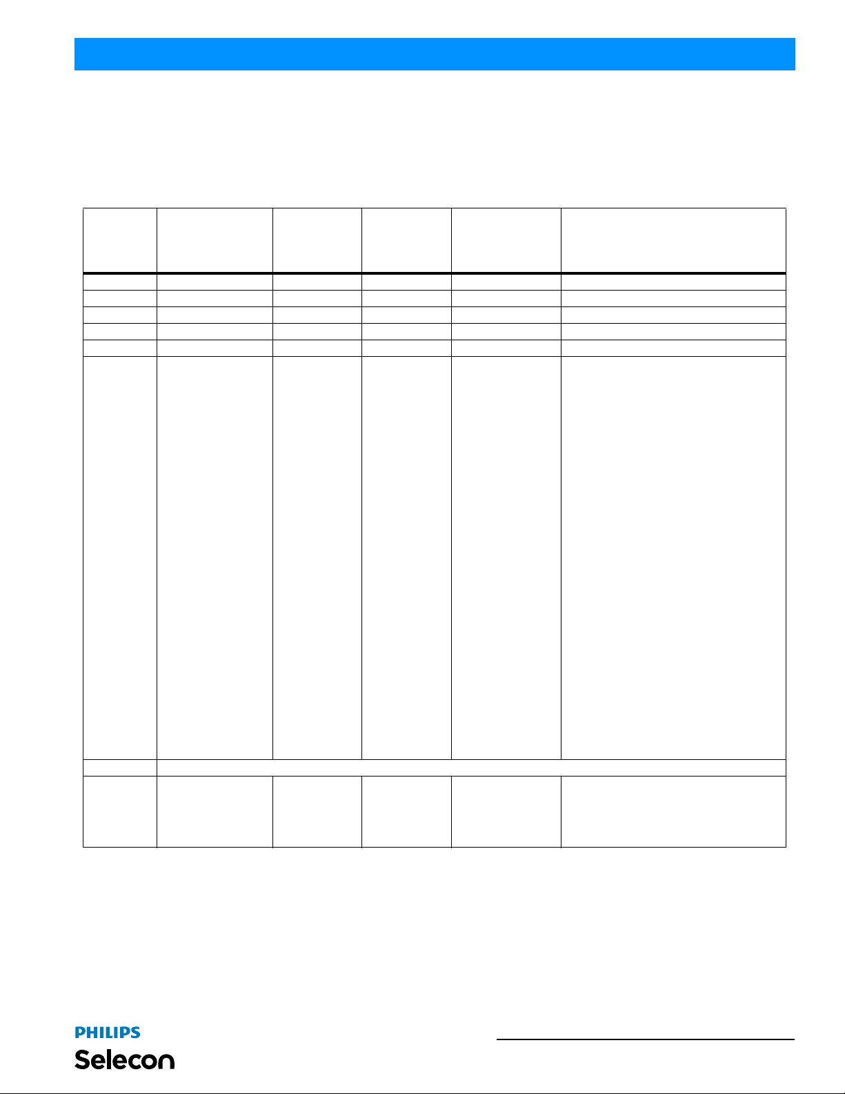
T able 2-1 provides DMX channel mapping of all DMX512 control values when the PL3 LED Luminaire is in 8-bit
DMX512 mode (as set by the luminaire’s menu system).
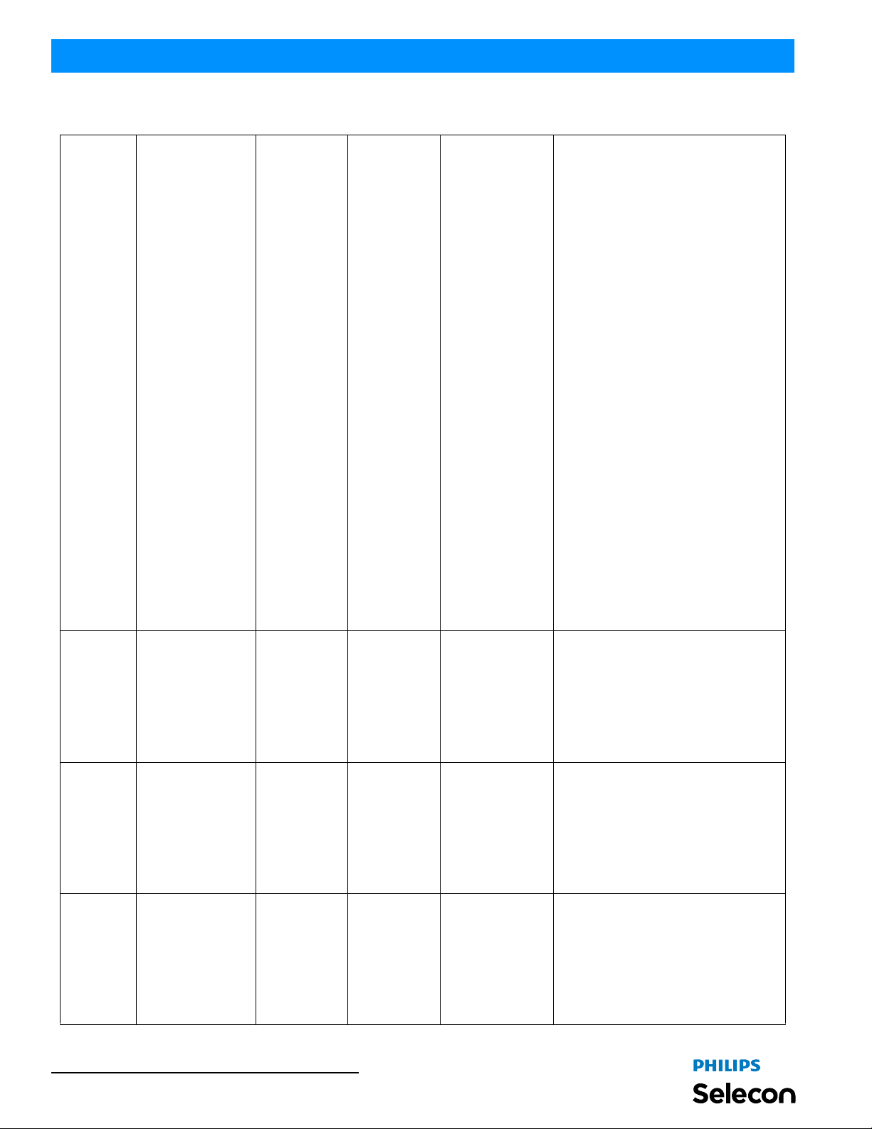
Table 2-1: PL3 Luminaire DMX Channel Mapping (8-Bit Mode)
Default -
DMX
Channel
1 Intensity 0 - 255 0 - 100% 0 8-bit control for Intensity of LED setti ngs.
2 Red 0 - 255 0 - 100% 0 8-bit control of Red LEDs from 0 to full.
3 Green 0 - 255 0 - 100% 0 8-bit control of Green LEDs from 0 to full.
4 Blue 0 - 255 0 - 100% 0 8-bit control of Blue LEDs from 0 to full.
5 White 0 - 255 0 - 100% 0 8-bit control of White LEDs from 0 to full.
6
7 Not used (for future use)
8 Timing 0 - 255 0 - 100% 255
Parameter Range DMX Range%
Preset Color Selection
Notes:
• Color Presets 5
through 25 are calibrated factory colors and can be
reloaded if needed
through the fixture’s
menu system.
• These colors have
been matched to
precise X and Y
coordinates at the
center of the beam
at wide angle, we
have given you the
ability to adjust
these colors as
your personal perception may vary.
0 - 255 0 - 100% 0
recommended
console default
values
Description
Used to access presets stored in fixture
firmware, such as CCT presets, defined gel
presets, and more.
No Preset Activated = DMX 0 - 3
Color Preset 0 (Off) = DMX 4 - 7
Color Preset 1 (Scratch Pad) = DMX 8 - 11
Color Preset 2 (Warm White) = DMX 12 - 15
Color Preset 3 (Cool White) = DMX 16 - 19
Color Preset 4 (Daylight) = DMX 20 - 23
Color Preset 5 (Arc White) = DMX 24 - 27
Color Preset 6 (Red) = DMX 28 - 31
Color Preset 7 (Yellow) = DMX 32 - 35
Color Preset 8 (Daylight Blue) = DMX 36 - 39
Color Preset 9 (Magenta) = DMX 40 - 43
Color Preset 10 (Kelly Green) = DMX 44 - 47
Color Preset 11 (Medium Amber) = DMX 48 - 51
Color Preset 12 (Lavender) = DMX 52 - 55
Color Preset 13 (Blue) = DMX 56 - 59
Color Preset 14 (Light Pink) = DMX 60 - 63
Color Preset 15 (Green) = DMX 64 - 67
Color Preset 16 (Pink) = DMX 68 - 71
Color Preset 17 (Amber White) = DMX 72 - 75
Color Preset 18 (Dark Fuchsia) = DMX 76 - 79
Color Preset 19 (Light Amber) = DMX 80 - 83
Color Preset 20 (Steel Blue) = DMX 84 - 87
Color Preset 21 (Lt. Green/Blue) = DMX 88 - 91
Color Preset 22 (Orange) = DMX 92 - 95
Color Preset 23 (Medium Pink) = DMX 96 - 99
Color Preset 24 (Cyan) = DMX 100 - 103
Color Preset 25 (Purple) = DMX 104 - 107
Color Preset 26 (Custom) = DMX 108 - 111
Color Preset 27 (Custom) = DMX 112 -115
Color Preset 28 (Custom) = DMX 116 - 119
Color Preset 29 (Custom) = DMX 120 - 123
Color Preset 30 (Custom) = DMX 124 - 127
Color Preset 31 (Custom) = DMX 128 - 131
Allows for timing control of both the intensity and
color parameters. Channel should default to 255
for smoothest actions using console and/or
manual fades. Refer to "PL3 Luminaire DMX
Timing Channel Detail" on page22 for more
information.
- Continued next page -
8-Bit Mode 19
Page 22
Installation & User’s Manual PL3 LED Luminaires
Table 2-1: PL3 Luminaire DMX Channel Mapping (8-Bit Mode)
Used to set different modes, parameters, and
functions of the luminaire. Set control channel
value for desired action. Hold value for at least 3
seconds. Set control channel value to 0 without
any scaling.
Default Setting on Console = DMX 0
Display On/Off = DMX 3 - 4
Reset All to Defaults = DMX 5 - 7
Quiet Mode = DMX 11 - 13
Normal Mode = DMX 14 - 15
Preset 1 Store = DMX 20 - 21
Preset 2 Store (Intensity Only) = DMX 22 - 23
Preset 3 Store (Intensity Only) = DMX 24 - 25
Preset 4 Store (Intensity Only) = DMX 26 - 27
Preset 5 Store = DMX 28 - 29
Preset 6 Store = DMX 30 - 31
Preset 7 Store = DMX 32 - 33
Preset 8 Store = DMX 34 - 35
Preset 9 Store = DMX 36 - 37
Preset 10 Store = DMX 38 - 39
9 Control 0 - 255 0 - 100% 0
10 Beam 0 - 255 0 - 100%
Pan
11
12
(See "Pan & Tilt DMX
Operation Notes" on
page 18 for more
information).
Tilt
(See "Pan & Tilt DMX
Operation Notes" on
page 18 for more
information).
0 - 255 0 - 100%
0 - 255 0 - 100%
DMX 127 (-50%,
Motor Stop)
DMX 127 (50%,
Motor Stop)
DMX 127 (50%,
Motor Stop)
- Continued next page -
Preset 11 Store = DMX 40 - 41
Preset 12 Store = DMX 42 - 43
Preset 13 Store = DMX 44 - 45
Preset 14 Store = DMX 46 - 47
Preset 15 Store = DMX 48 - 49
Preset 16 Store = DMX 50 - 51
Preset 17 Store = DMX 52 - 53
Preset 18 Store = DMX 54 - 55
Preset 19 Store = DMX 56 - 57
Preset 20 Store = DMX 58 - 59
Preset 21 Store = DMX 60 - 61
Preset 22 Store = DMX 62 - 63
Preset 23 Store = DMX 64 - 65
Preset 24 Store = DMX 66 - 67
Preset 25 Store = DMX 68 - 69
Preset 26 Store = DMX 70 - 71
Preset 27 Store = DMX 72 - 73
Preset 28 Store = DMX 74 - 75
Preset 29 Store = DMX 76 - 77
Preset 30 Store = DMX 78 - 79
Preset 31 Store = DMX 80 - 81
Fixture Reset* = DMX 250 - 255
Controls zoom mechanism motor in 3 speeds,
forward and backwards as follows . . .
Motor Stop = DMX 0 - 15
Motor <<< Fast = DMX 16 - 49
Motor << Medium = DMX 50 - 84
Motor < Slow = DMX 85 - 119
Motor Stop = DMX 120 - 135
Motor > Slow = DMX 136 - 170
Motor >> Medium = DMX 171 - 204
Motor >>> Fast = DMX 205 - 238
Motor Stop = DMX 239 - 255
Controls Pan motor in 3 speeds, forward and
backwards as follows . . .
Motor Stop = DMX 0 - 15
Motor <<< Fast = DMX 16 - 49
Motor << Medium = DMX 50 - 84
Motor < Slow = DMX 85 - 119
Motor Stop = DMX 120 - 135
Motor > Slow = DMX 136 - 170
Motor >> Medium = DMX 171 - 204
Motor >>> Fast = DMX 205 - 238
Motor Stop = DMX 239 - 255
Controls Tilt motor in 3 speeds, forward and
backwards as follows . . .
Motor Stop = DMX 0 - 15
Motor <<< Fast = DMX 16 - 49
Motor << Medium = DMX 50 - 84
Motor < Slow = DMX 85 - 119
Motor Stop = DMX 120 - 135
Motor > Slow = DMX 136 - 170
Motor >> Medium = DMX 171 - 204
Motor >>> Fast = DMX 205 - 238
Motor Stop = DMX 239 - 255
20 DMX CONTROL
Page 23
PL3 LED Luminaires
Installation & User’s Manual
3. DMX 3-Channel (3-Chan) Mode
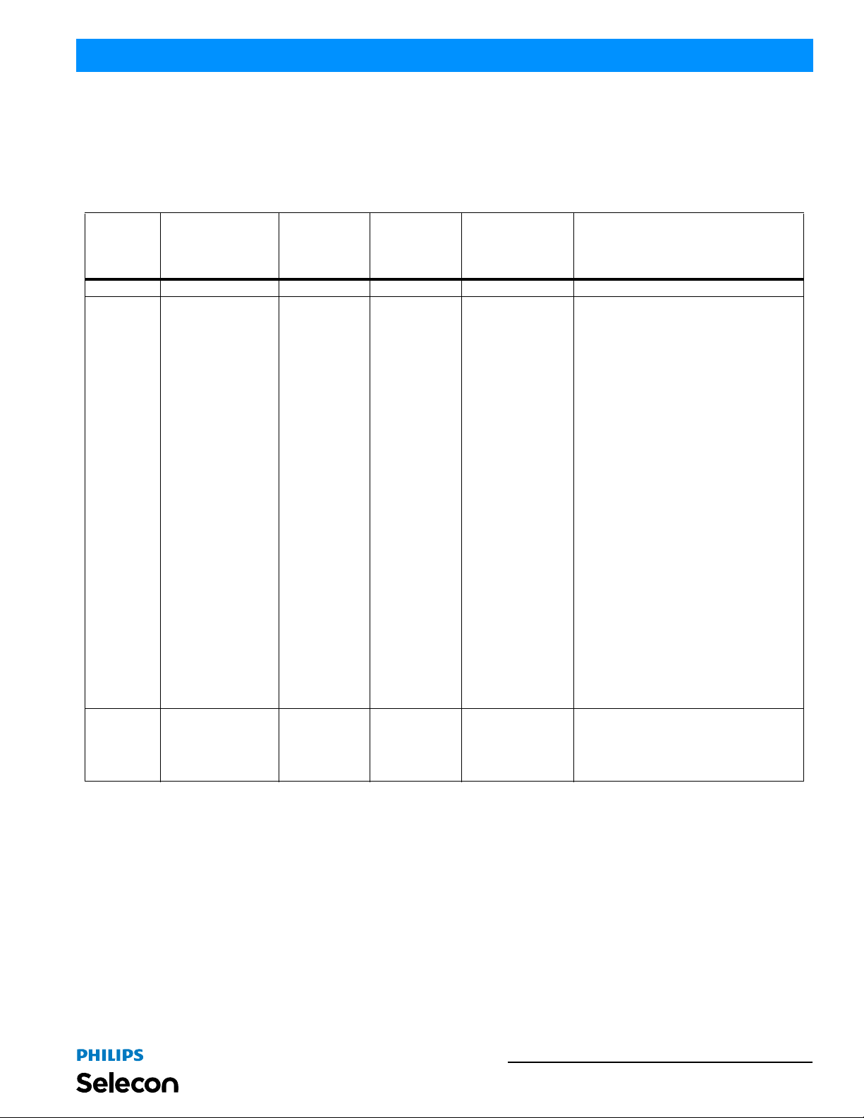
T able 2-1 provides DMX channel mapping of all DMX512 control values when the PL3 LED Luminaire is in 3Channel (3-Chan) DMX512 mode (as set by the luminaire’s menu system).
Table 2-2: PL3 Luminaire DMX Channel Mapping (3-Chan Mode)
Default -
DMX
Channel
1 Intensity 0 - 255 0 - 100% 0 8-bit control for Intensity of LED setti ngs.
2
3 Timing 0 - 255 0 - 100% 255
Parameter Range DMX Range%
Preset Color Selection
Notes:
• Color Presets 5
through 25 are calibrated factory colors and can be
reloaded if needed
through the fixture’s
menu system.
• These colors have
been matched to
precise X and Y
coordinates at the
center of the beam
at wide angle, we
have given you the
ability to adjust
these colors as
your personal perception may vary.
0 - 255 0 - 100% 0
recommended
console default
values
Description
Used to access presets stored in fixture
firmware, such as CCT presets, defined gel
presets, and more.
No Preset Activated = DMX 0 - 3
Color Preset 0 (Off) = DMX 4 - 7
Color Preset 1 (Scratch Pad) = DMX 8 - 11
Color Preset 2 (Warm White) = DMX 12 - 15
Color Preset 3 (Cool White) = DMX 16 - 19
Color Preset 4 (Daylight) = DMX 20 - 23
Color Preset 5 (Arc White) = DMX 24 - 27
Color Preset 6 (Red) = DMX 28 - 31
Color Preset 7 (Yellow) = DMX 32 - 35
Color Preset 8 (Daylight Blue) = DMX 36 - 39
Color Preset 9 (Magenta) = DMX 40 - 43
Color Preset 10 (Kelly Green) = DMX 44 - 47
Color Preset 11 (Medium Amber) = DMX 48 - 51
Color Preset 12 (Lavender) = DMX 52 - 55
Color Preset 13 (Blue) = DMX 56 - 59
Color Preset 14 (Light Pink) = DMX 60 - 63
Color Preset 15 (Green) = DMX 64 - 67
Color Preset 16 (Pink) = DMX 68 - 71
Color Preset 17 (Amber White) = DMX 72 - 75
Color Preset 18 (Dark Fuchsia) = DMX 76 - 79
Color Preset 19 (Light Amber) = DMX 80 - 83
Color Preset 20 (Steel Blue) = DMX 84 - 87
Color Preset 21 (Lt. Green/Blue) = DMX 88 - 91
Color Preset 22 (Orange) = DMX 92 - 95
Color Preset 23 (Medium Pink) = DMX 96 - 99
Color Preset 24 (Cyan) = DMX 100 - 103
Color Preset 25 (Purple) = DMX 104 - 107
Color Preset 26 (Custom) = DMX 108 - 111
Color Preset 27 (Custom) = DMX 112 -115
Color Preset 28 (Custom) = DMX 116 - 119
Color Preset 29 (Custom) = DMX 120 - 123
Color Preset 30 (Custom) = DMX 124 - 127
Color Preset 31 (Custom) = DMX 128 - 131
Allows for timing control of both the intensity and
color parameters. Channel should default to 255
for smoothest actions using console and/or
manual fades. Refer to "PL3 Luminaire DMX
Timing Channel Detail" on page22 for more
information.
DMX 3-Channel (3-Chan) Mode 21
Page 24
Installation & User’s Manual PL3 LED Luminaires
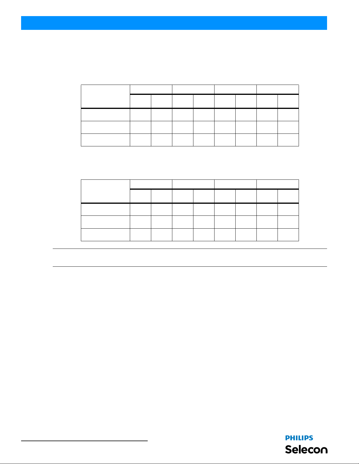
4. Lighting Console Settings for Preset White
16-Bit Mode
Below are the DMX512 console values and levels* for Warm White, Cool White, and Day Light presets in 16-bit
mode.
Red Channel Green Channel Blue Channel White Channel
White Preset
Warm White 65535 100 36700 56 0 0 47185 72
Cool White 65535 100 41287 63 8520 13 61603 94
Day Light 65535 100 53739 82 26214 40 58982 90
8-Bit or 3-Channel Modes
Below are the DMX512 console values and levels* for Warm White, Cool White, and Day Light presets in 8-bit or 3Channel modes.
White Preset
DMX
Value
DMX
Value
DMX%
Red Channel Green Channel Blue Channel White Channel
DMX%
DMX
Value
DMX
Value
DMX%
DMX%
DMX
Value
DMX
Value
DMX%
DMX%
DMX
Value
DMX
Value
DMX%
DMX%
Warm White (3200K) 255 100 163 64 0 0 217 85
Cool White (4000K) 255 100 194 76 46 18 255 100
Day Light (5600K) 255 100 237 93 130 51 255 100
Note: *Values and levels shown for Preset White (in 16-Bit, 8-Bit, or 3-Channel modes) are approximate. Due to the
characteristics of LED technology, actual values may vary slightly between fixtures.
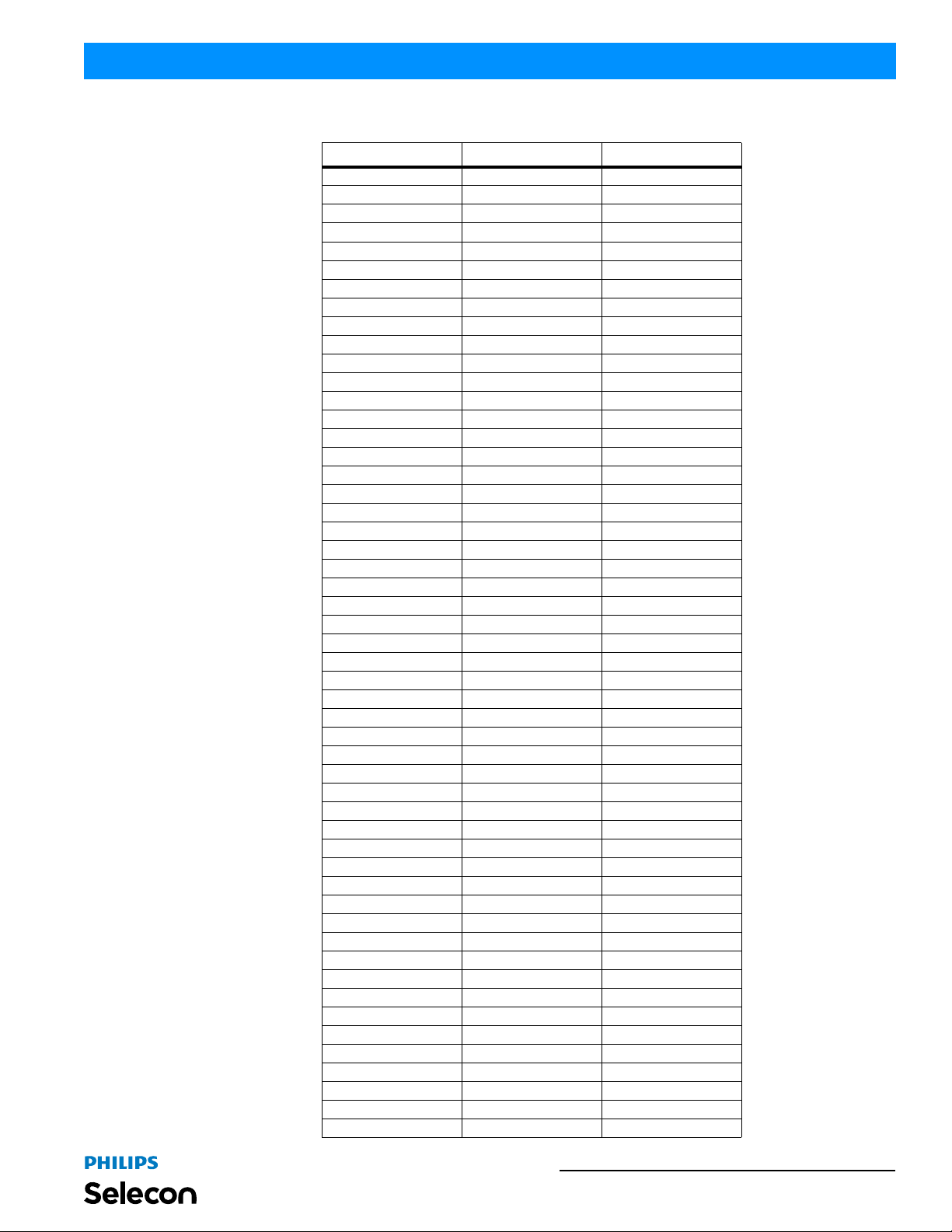
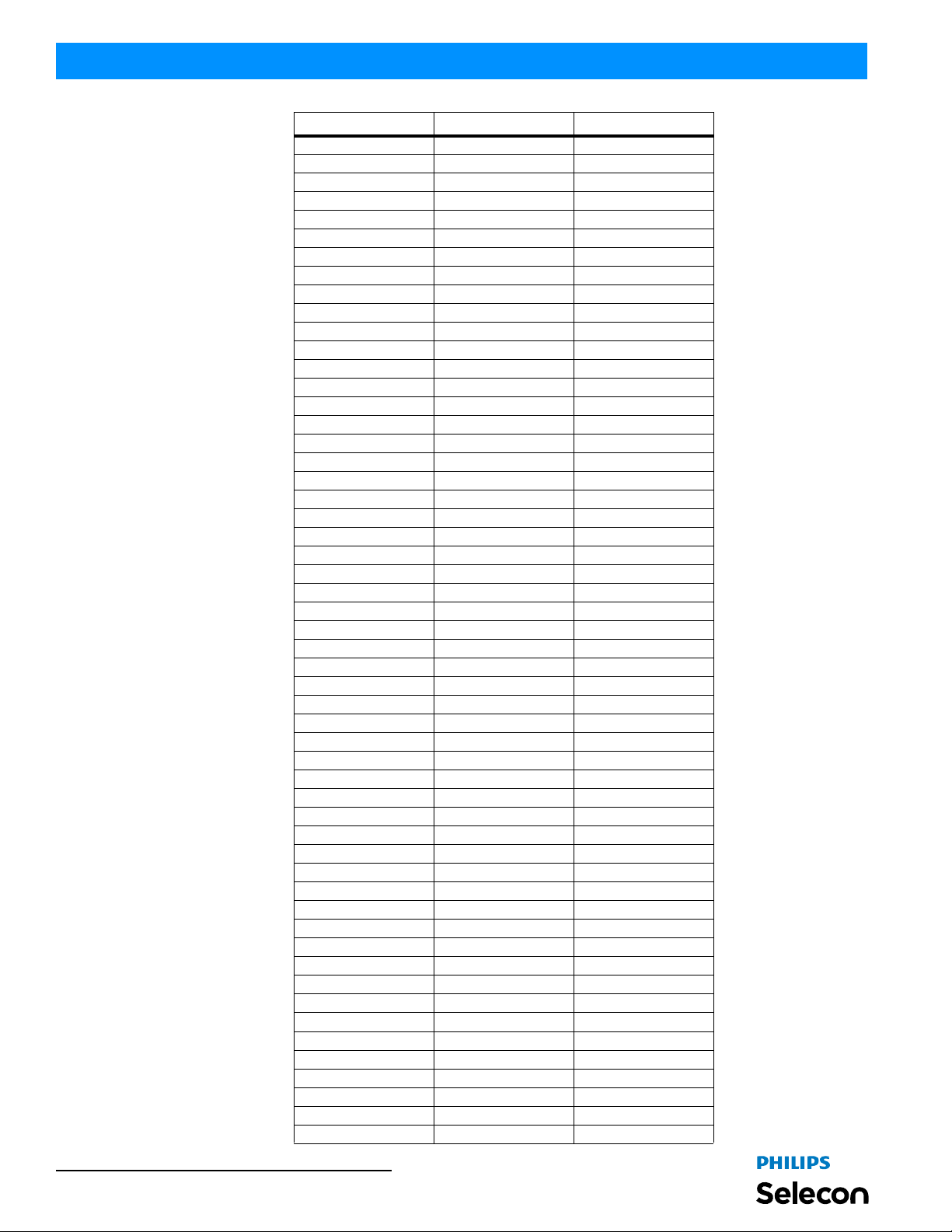
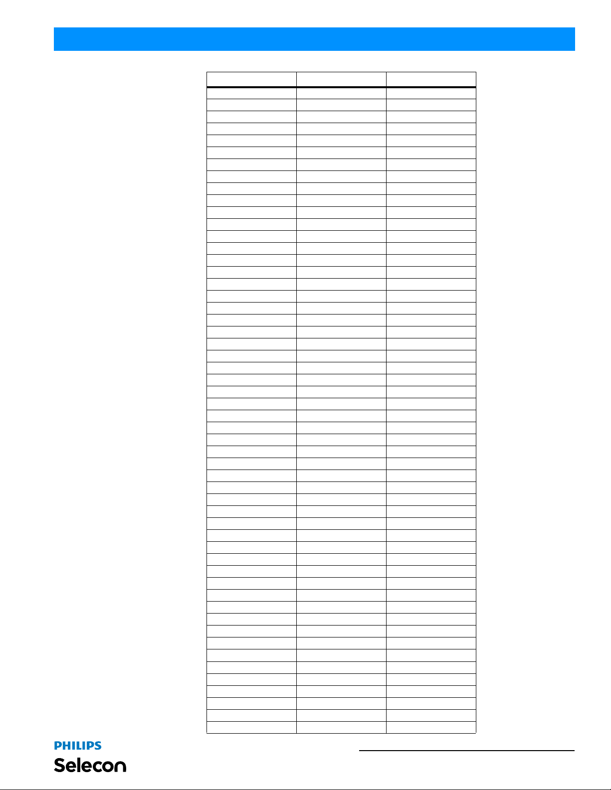
5. PL3 Luminaire DMX Timing Channel Detail
Timing channel control improves the timed moves of certain groups of parameters. The PL3 LED Luminaire provides
two timing channels in 16-bit mode (one for intensity time and one for color time) and one timing channel in 8-b it
(color and intensity timing combined). The luminaire uses its timing channel value to calculate a smooth continuous
operation for a given time and transition.
Guidelines:
• Timing channels support time values from zero to 169 seconds.
• To use a timing channel instead of console timing, it is recommended to set the timing channel to the desired value
and set cue and/or console cue fade time to zero. A combination of time controls can produce unexpected results.
• The default value setting in the profile should be 255 (proportional control) to allow smooth operation when using
console timing.
• The timing chan nel dat a sho uld change as a snap. A zero value will give the fastest operation, however, without
any smoothing this can appear "steppy" in console timed moves.
Refer to "PL3 Luminaire Timing Channel Detail" on page 23 for more information.
22 DMX CONTROL
Page 25
PL3 LED Luminaires
Installation & User’s Manual
Table 3: PL3 Luminaire Timing Channel Detail
% Value DMX = Seconds
0 0 (Full Speed)
10.2
20.4
130.6
40.8
251
61.2
71.4
381.6
91.8
4102
11 2.2
12 2.4
5132.6
14 2.8
6153
16 3.2
17 3.4
7183.6
19 3.8
8204
21 4.2
22 4.4
9234.6
24 4.8
10 25 5
26 5.2
27 5.4
11 28 5.6
29 5.8
30 6
12 31 6.2
32 6.4
13 33 6.6
34 6.8
35 7.0
14 36 7.2
37 7.4
15 38 7.6
39 7.8
40 8
16 41 8.2
42 8.4
17 43 8.6
44 8.8
45 9
18 46 9.2
47 9.4
19 48 9.6
49 9.8
50 10
20 51 10.2
PL3 Luminaire DMX Timing Channel Detail 23
Page 26
Installation & User’s Manual PL3 LED Luminaires
% Value DMX = Seconds
52 10.4
53 10.6
21 54 10.8
55 11
22 56 11.2
57 11.4
58 11.6
23 59 11.8
60 12
24 61 12.2
62 12.4
63 12.6
25 64 12.8
65 13
26 66 13.2
67 13.4
68 13.6
27 69 13.8
70 14
28 71 14.2
72 14.4
73 14.6
29 74 14.8
75 15
30 76 15.2
77 15.4
78 15.6
31 79 15.8
80 16
81 16.2
32 82 16.4
83 16.6
33 84 16.8
85 17
86 17.2
34 87 17.4
88 17.6
35 89 17.8
90 18
91 18.2
36 92 18.4
93 18.6
37 94 18.8
95 19
96 19.2
38 97 19.4
98 19.6
39 99 19.8
100 20
101 21
40 102 22
103 23
104 24
41 105 25
24 DMX CONTROL
Page 27
PL3 LED Luminaires
Installation & User’s Manual
% Value DMX = Seconds
106 26
42 107 27
108 28
109 29
43 110 30
111 31
44 112 32
113 33
114 34
45 115 35
116 36
46 117 37
118 38
119 39
47 120 40
121 41
48 122 42
123 43
124 44
49 125 45
126 46
127 47
50 128 48
129 49
51 130 50
131 51
132 52
52 133 53
134 54
53 135 55
136 56
137 57
54 138 58
139 59
55 140 60
141 61
142 62
56 143 63
144 64
57 145 65
146 66
147 67
58 148 68
149 69
59 150 70
151 71
152 72
60 153 73
154 74
155 75
61 156 76
157 77
62 158 78
159 79
PL3 Luminaire DMX Timing Channel Detail 25
Page 28
Installation & User’s Manual PL3 LED Luminaires
% Value DMX = Seconds
160 80
63 161 81
162 82
64 163 83
164 84
165 85
65 166 86
167 87
66 168 88
169 89
170 90
67 171 91
172 92
68 173 93
174 94
175 95
69 176 96
177 97
178 98
70 179 99
180 100
71 181 101
182 102
183 103
72 184 104
185 105
73 186 106
187 107
188 108
74 189 109
190 110
75 191 111
192 112
193 113
76 194 114
195 115
77 196 116
197 117
198 118
78 199 119
200 120
79 201 121
202 122
203 123
80 204 124
205 125
81 206 126
207 127
208 128
82 209 129
210 130
211 131
83 212 132
213 133
26 DMX CONTROL
Page 29
PL3 LED Luminaires
% Value DMX = Seconds
84 214 134
215 135
216 136
85 217 137
218 138
86 219 139
220 140
221 141
87 222 142
223 143
88 224 144
225 145
226 146
89 227 147
228 148
229 149
90 230 150
231 151
91 232 152
233 153
234 154
92 235 155
236 156
93 237 157
238 158
239 159
94 240 160
241 161
95 242 162
243 163
244 164
96 245 165
246 166
97 247 167
248 168
249 169
98 250* 60mS
251* 80mS
99 252* 100mS
253* 120mS
254* 140mS
100
255*
(default)
160mS
Installation & User’s Manual
Note: * DMX values 250 to 255 provide smoothing when using console fade timing. DMX value 255 (recommended
default) will provide the smoothest timing.
PL3 Luminaire DMX Timing Channel Detail 27
Page 30
Installation & User’s Manual PL3 LED Luminaires
INFRARED REMOTE CONTROL
1. Infrared Remote Control Overview
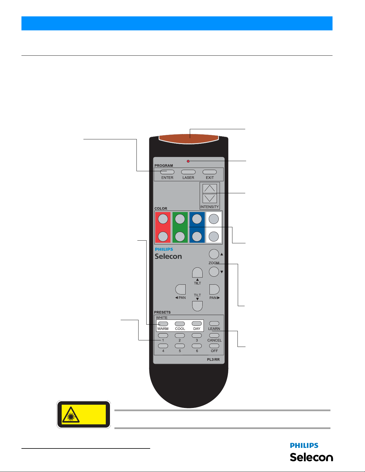
The PL3IRR infrared preset programming remote (sold separately) allows users convenient access to adjust and
program luminaire parameters - presets (1 through 6 and Off), intensity, preset color temperatures, zoom/focus
control, or full color mixing from the floor. Before using the remote, please familiarize yourself with all available
controls shown in Figure 3.
Infrared Remote Control Features
Laser / IR Window -
Program Enter - Press ENTER to set the
luminaire to Luminaire Select.
Laser (Luminaire Selector) - Press
LASER to select individual luminaire
for programming / adjustment.
Exit - Press EXIT to exit
programming mode.
Preset (White Color Temperature) Allows selection of Warm, Cool or Day
color temperatures.
Note, only intensities may be stored
on White Color Temperature presets.
These presets cannot be edited or
changed
Laser and IR programming emits from
this end.
PL3IRR LED (indicator) The LED indicator will flash each time
a button is pressed.
Intensity Raise/Lower Press top button to raise intensity and
bottom button to lower it. Tap the up
for 2% increase or tap down for a 1%
decrease. Press and hold (top or
bottom button) for sequential raise/
lower.
Individual LED Color Adjustment Allows the raising or lowering of
individual LED colors. Press top
button to change color and bottom
button to lower it. Tap the up for 2%
increase or tap down for a 1%
decrease. Press and hold (top or
bottom button) for sequential raise/
lower.
Presets (6 Levels or Off) Allows selection and programming of
one of six Presets (1 through 6) or
Preset Off.
Notes:
• Preset Off cannot be edited or
changed.
• Presets 1 through 6 on
remote control (equate to)
Presets 5 through 10 on PL3
LASER RADIATION
DO NOT STAREINTO BEAM
CLASS 2 LASER PRODUCT
LASER DIODE
WAVELENGTH: 630 - 680 nm
MAX OUTPUT: <5 mW
28 INFRARED REMOTE CONTROL
Zoom Allows for adjustment of the fixture’s
zoom assembly for focusing.
Note: Pan / Tilt controls for future use.
Learn After adjustments are made, the Learn
button (in conjunction with a preset
button) stores the new settings to a
specific preset if desired.
Cancel Cancels the learn features (any
programming made will not be
recorded) RGBW will not be changed.
WARNING! THIS DEVICE IS A CLASS 2 LASER. DO NOT STARE OR LOOK
DIRECTLY INTO BEAM.
Figure 3: PL3IRR Programming Remote
Page 31
PL3 LED Luminaires
To select and program PL3 LED lumina ire with PL3IRR remote:
Note: The IR, on the PL3 LED luminaire, must be set to "Enabled" in order for the PL3IRR remote to communicate
and control the fixture. Each luminaire to be programmed/adjusted needs to be selected and programmed/adjusted
individually.
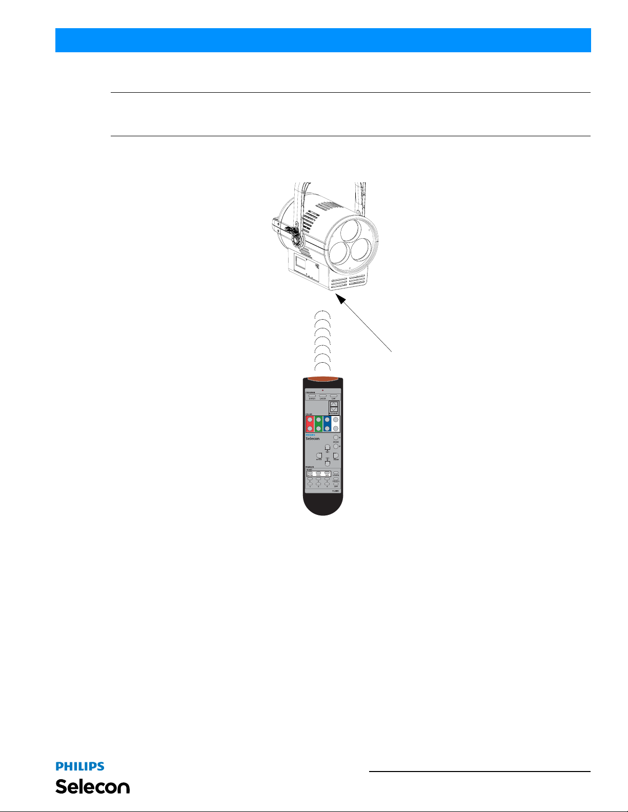
Step 1. Aim PL3IRR programming remote (as shown in Figure 4) and press "Enter" button. Luminaire will flash an
LED (at bottom of unit) to provide a target for the laser to aim at. Luminaire will look for laser beam (from
PL3IRR) to enter selected mode.
Installation & User’s Manual
PL3 LED Luminaire
PL3 Luminaire IR Port
(located underneath luminaire)
PL3IRR Remote Control
Figure 4: PL3 LED Luminaire Programming / Control
Step 2. Point PL3IRR remote directly at luminaire IR window and press "Laser" button. Luminaire to be
programmed or adjusted is now selected.
Note: At luminaire IR port, a Blue LED will illuminate when the fixture is in programming mode and blink Red when
buttons are pressed on IR remote to confirm it sees the remote and is receiving commands.
Step 3. Set luminaire to preset or make adjustments as desired.
Step 4. To save settings, press "Learn" button and then press any Preset button (except Off . Off cannot be
programmed). Preset is now saved. To cancel programming, press "Cancel" button.
Step 5. After programming or adjustments are complete, press "Exit" button. Repeat, as desired, on additional
luminaires to be programmed/adjusted.
Infrared Remote Control Overview 29
Page 32
Installation & User’s Manual PL3 LED Luminaires
CLEANING AND CARE
WARNING! All cleaning should be performed wi th power completely removed from the luminaire. Never remove
protective covers. Wear appropriate protective eye wear and gloves when cleaning the fixture. All service and
maintenance, other than described herein, should be performed by qualified personnel or Authorized Service Center.
1. Special Cleaning and Care Instructions
Being a solid-state fixture, the PL3 LED Luminaire requires very little routine mainten ance by the user. This section
covers portions of the luminaire that can be removed for cleaning.
The PL3 Luminaire requires special care when it comes to cleaning the front lens assembly. Additional care needs to
be taken with the plastic components because they are much easier to scratch or damage than glass.
WARNING! Do not use acidic solutions, such as ammonia-based cleaners, acetone, or other harsh solvents on or
near the PL3 LED Luminaire. These types of cleaners and solvents will attack the luminaire’s polymers and will
permanently damage the optics or housings of the fixture.
The following is a list of cleaning materials required to care for your PL3 LED Luminaire:
• Lint free lens tissue
• Lint or powder free gloves
• Mild soap solution com prised of 1 to 2% mild detergent and 98 - 99% distilled water. If mild soap solution does
not clean after several attempts, reagent grade isopropyl alcohol may be used.*
Note: *Reagent grade isopropyl alcohol is good to use on the PL3 LED Luminaire plastic optics with anti-reflection
coatings.
If the lens is still dirty after using isopropyl alcohol, for instance if fingerprints or oil is just redistributed and not
cleaned off the optic, then a mild soap and water solution can be used to gently wash the lens. Repeat the cleani ng
with isopropyl alcohol to eliminate streaks and soap residue.
If you have any questions regarding the use or care of you r PL3 LED Luminaire, please contact Philips Selecon
technical support or your local Authorized Dealer.
2. Lens Cleaning
Front Lens (Exterior)
To clean the exterior front lens:
Step 1. Turn off luminaire and allow to cool completely.
Step 2. Apply a small amount of reagent grade isopropyl alcohol to lint-free lens tissue.
Step 3. Wipe all debris, dirt, fingerprints, etc. from lens.
Step 4. Using a second lint-free lens tissue, wipe off any alcohol residue.
30 CLEANING AND CARE
Page 33

PL3 LED Luminaires
3. Service and Maintenance
For all other service and maintenance issues, please contact your local Philips Selecon office or an Authorized
Service Center.
WARNING! Disassembly, alterations, unauthorized service, etc. will void the product warranty. There are no userserviceable parts in this product. Contact your local Philips Selecon office or an Authorized Service Center for
technical support and service.
4. Accessories
Only Philips Selecon approved accessories should be used with your PL3 LED Luminaire. For a list of available
accessories from Philips Selecon, please see "ACCESSORIES" on page 3. For questions regarding accessories,
please contact your local Authorized Philips Selecon Dealer or Philips Selecon office.
Installation & User’s Manual
Service and Maintenance 31
Page 34
Installation & User’s Manual PL3 LED Luminaires
TROUBLESHOOTING
1. Troubleshooting Guide
The chart below provides possible causes and remedies for various error messages and/or symptoms.
WARNING! Any service and maintenance (i nclud ing troubleshooting), other than described herein should be
performed by an Authorized Philips Selecon Dealer or Service Center. The PL3 LED Luminaire contains no userserviceable parts.
Description Symptom Possible Cause/Remedy
No light output.
No power at luminaire. Luminaire does not power up
DMX Data Control.
IR remote programming.
LED (light) is getting dimmer.
Local programming.
Pan & Tilt Movement.
(Note, PL3MKIT, sold separately,
must be installed)
Fixture will not produce or
output light
Fixture will not respond to DMX
commands.
Fixture will not respond to IR
remote programming unit.
Fixture appears not to be
operating at full brightness.
Unit will not allow local
programming or changes.
Unit will not follow Pan and/or
Tilt Commands.
Unit is set to Preset Off...
Make sure unit is set to proper Preset.
DMX command to 0 intensity...
Adjust intensity to higher level.
Circuit not energized...
verify circuit breaker is turned on.
Not plugged in...
ensure A/C cable is connected to power source.
Power cable wired incorrectly. ..
verify power cable and connector are wired correctly.
See "Connecting Power" on page5 for more information.
Not detecting DMX data...
Disconnect and reconnect DMX input cable.
Unit is not set to be controlled by DMX - check menu settings.
Check all DMX connections (at control source and luminaire).
DMX data cable not wired correctly or has a broken conductor...
check DMX data cable for proper wiring.
See "Connecting to the DMX512 Network" on page5 for more
information.
Luminaire not selected by laser...
Reselect luminaire by repeating luminaire selection step.
Not seeing IR remote control...
Make sure batteries are good in remote. Try fresh, fully ch arged
batteries.
Make sure IR is enabled in the fixture menu.
Insure IR remote is pointing at IR window in luminaire and that the re
is nothing in between IR remote and luminaire IR window.
Clean luminaire IR window.
Luminaire has detected an over temperature condition...
The luminaire will reduce power to its LED if it senses that the LED
is operating over the specified temperature. LED temperature is
read and recorded through a thermistor imbedded in the LED chip.
Fan is not operating. Listen for fan operation or adjust settings to
increase fan speed. On luminaires with a display check system
status menu for status of fans and LED operation.
Password protection is on (locked)...
Input proper password to allow local programming and/or
adjustments.
Unit is controlled by DMX or Vision.net...
Disconnect input cables to check issue.
Unit is not DMX enabled...
Disconnect and reconnect DMX input cable.
Unit is not set to be controlled by DMX - check menu settings.
Check all DMX connections (at control source and luminaire).
DMX data cable not wired correctly or has a broken conductor...
check DMX data cable for proper wiring.
See "Connecting to the DMX512 Network" on page5 for more
information.
See "Pan & Tilt DMX Operation Notes" on page 18 for more
information on Pan and Tilt settings.
Refer to PL3MKIT installation guide for more information.
32 TROUBLESHOOTING
Page 35
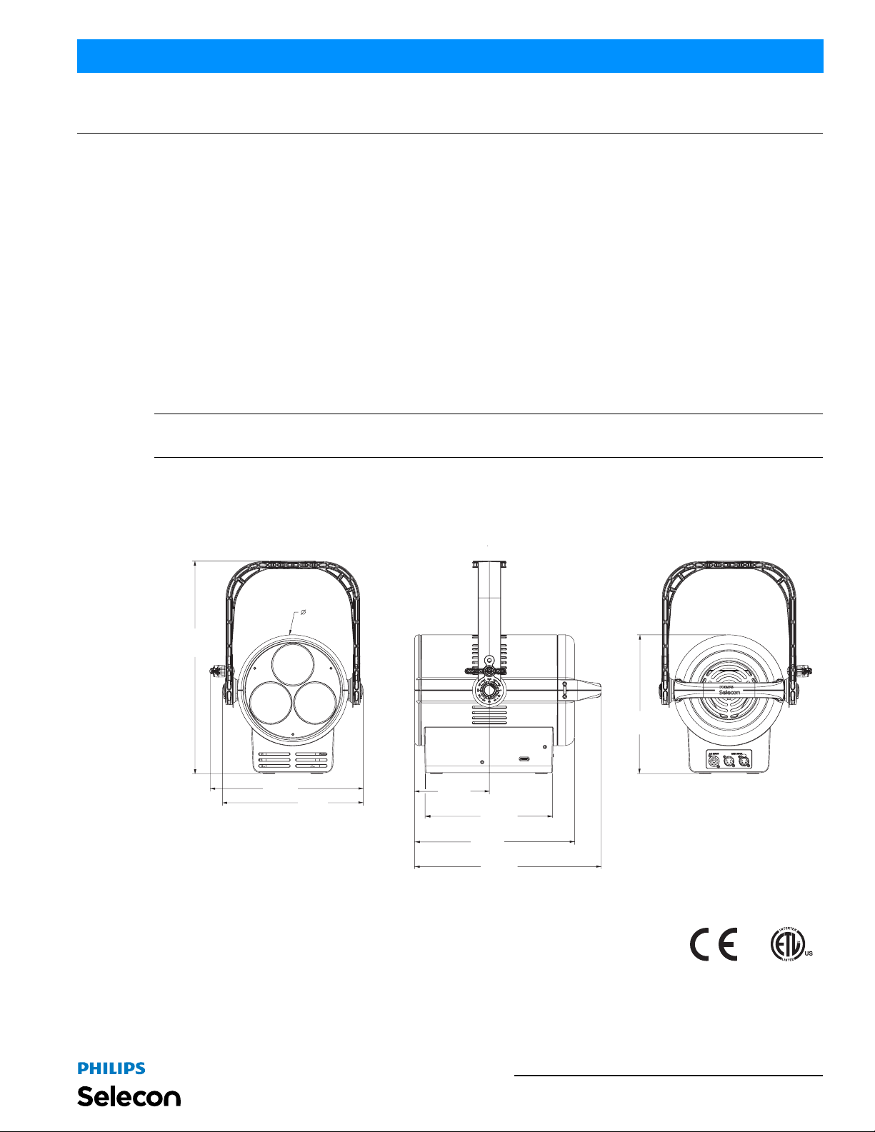
PL3 LED Luminaires
C
TECHNICAL SPECIFICATIONS
1. PL3 LED Luminaire Specifications
Source: 3 Each, True RGBW 120 Watt LED chips
Beam Spread: 15 to 55 degrees
Light Output: > 6,000 lumens
Color Temperature: 3000 - 5600K (user adjustable)
Input Voltage: 120V to 240V (+/- 10%, auto-ranging)
Current: 4.60 Amps (120V) / 2.35 Amps (240V)
Frequency: 50/60Hz
Ambient Temperature: 0 to 50 degrees C (32 to 122 degrees F)
Humidity: 5%-95% Non condensing
Cooling: Forced-Air
Weight: 22.1 lbs (10.1 kg) - Luminaire only (no accesso ries)
Compliance: ETL / cETL Listed (North America models) and CE Marked (International models)
Note: For complete model specifications, features, and accessories, refer to the product specification sheet or visit
the Philips Selecon web site at www.seleconlight.com for more details.
Installation & User’s Manual
2. PL3 LED Luminaire Dimensions
Dimensions
9.75 in /
247.7 mm
18.7 in /
475.0 mm
13.5 in /
343.0 mm
12.4 in /
315.0 mm
167.6 mm
6.6 in /
11.2 in /
284.5 mm
14.1 in /
358.1 mm
16.4 in /
416.6 mm
12.2 in /
310.0 mm
PL3 LED Luminaire Specifications 33
Page 36
 Loading...