

VFC Radiant & Convector
Fire Range
With upgradeable control valve
Instructions for Use,
Installation and Servicing
For use in GB, IE (Great Britain and Eire)
PR0641 Issue 7 (December 2006
)
IMPORTANT
The chimney must be swept before installation. Do not attempt to burn rubbish on this fire. This fire has a naked flame.
A suitable guard should be used for the protection of young children, the elderly or infirm
Please read these instructions carefully and keep them in a safe place. They will be needed when servicing the fire.
The commissioning sheet found in these instructions should be completed by the installer.
This appliance has been certified for use in countries other than those stated. To install this appliance in these countries, it is essential to obtain the
translated instructions and in some cases the appliance will require modification. Contact Gazco for further information.

2
CONTENTS
PAGE
Commissioning Check List 3
USER INSTRUCTIONS 4
INSTALLATION INSTRUCTIONS
Technical Specifications 8
Site Requirements 9
Installation 11
Commissioning 16
SERVICING INSTRUCTIONS
Servicing Requirements 17
Fault Finding 18
How to replace parts 19
Basic spare parts list 22
3
FLUE CHECK PASS FAIL
1. Flue is correct for appliance
2. Flue flow test
3. Spillage test
GAS CHECK
1. Gas soundness & let by test
2. Standing pressure test mb
3. Appliance working pressure (on High Setting) mb
NB All other gas appliances must be operating on full
4. Gas rate m3/h
5. Does ventilation meet appliance requirements
6. Have controls been upgraded (Upgradeable models only) 8455 Standard YES NO
APPLIANCE COMMISSIONING CHECKLIST
Dealer. . . . . . . . . . . . . . . . . . . . . . . . . . . . . . . . . . . . . . . . . . . . . . . . . . . . . . . . . . . . . . . . . . . . . . .
. . . . . . . . . . . . . . . . . . . . . . . . . . . . . . . . . . . . . . . . . . . . . . . . . . . . . . . . . . . . . . . . . . . . . . . . . . . . . . . .
. . . . . . . . . . . . . . . . . . . . . . . . . . . . . . . . . . . . . . . . . . . . . . . . . . . . . . . . . . . . . . . . . . . . . . . . . . . . . . . .
Contact No. . . . . . . . . . . . . . . . . . . . . . . . . . . . . . . . . . . . . . . . . . . . . . . . . . . . . . . . . . . . . . . .
Date of Purchase. . . . . . . . . . . . . . . . . . . . . . . . . . . . . . . . . . . . . . . . . . . . . . . . . . . . . . . .
Model No. . . . . . . . . . . . . . . . . . . . . . . . . . . . . . . . . . . . . . . . . . . . . . . . . . . . . . . . . . . . . . . . . .
Serial No. . . . . . . . . . . . . . . . . . . . . . . . . . . . . . . . . . . . . . . . . . . . . . . . . . . . . . . . . . . . . . . . . . .
Gas Type . . . . . . . . . . . . . . . . . . . . . . . . . . . . . . . . . . . . . . . . . . . . . . . . . . . . . . . . . . . . . . . . . . .
Installation Company. . . . . . . . . . . . . . . . . . . . . . . . . . . . . . . . . . . . . . . . . . . . . . . . . .
. . . . . . . . . . . . . . . . . . . . . . . . . . . . . . . . . . . . . . . . . . . . . . . . . . . . . . . . . . . . . . . . . . . . . . . . . . . . . . . . .
. . . . . . . . . . . . . . . . . . . . . . . . . . . . . . . . . . . . . . . . . . . . . . . . . . . . . . . . . . . . . . . . . . . . . . . . . . . . . . . . .
Engineer . . . . . . . . . . . . . . . . . . . . . . . . . . . . . . . . . . . . . . . . . . . . . . . . . . . . . . . . . . . . . . . . . . . .
Contact No.. . . . . . . . . . . . . . . . . . . . . . . . . . . . . . . . . . . . . . . . . . . . . . . . . . . . . . . . . . . . . . . .
Corgi Reg No.. . . . . . . . . . . . . . . . . . . . . . . . . . . . . . . . . . . . . . . . . . . . . . . . . . . . . . . . . . . . .
Date of Installation . . . . . . . . . . . . . . . . . . . . . . . . . . . . . . . . . . . . . . . . . . . . . . . . . . . . .
IMPORTANT NOTICE
Explain the operation of the appliance to the end user, hand the completed instructions to them for safe keeping,
as the information will be required when making any guaranteed claims.
DEALER AND INSTALLER INFORMATION
This product is guaranteed for 2 years from the date of installation, as set out in the terms and conditions of sale between Gazco and
your local Gazco dealer. This guarantee will be invalid, to the extent permitted by law, if the above Appliance Commissioning
Checklist is not fully completed by the installer and available for inspection by a Gazco engineer. The guarantee will only be valid
during the second year, to the extent permitted by law, if the annual service recommended in the Instructions for Use has been
completed by a Corgi registered engineer, and a copy of the service visit report is available for inspection by a Gazco engineer.
4
USER INSTRUCTIONS
1.1 Installation and servicing must only be carried out by a
competent person.
1.2 In your own interest, and those of safety, this appliance must
be installed by a competent person in accordance with local
and national codes of practice. Failure to install the appliance
correctly could lead to prosecution.
1.3 In all correspondence, please quote the appliance type and
serial number which can be found on the databadge.
1.4 Ensure that curtains are not positioned above the fire and that
there is a 300mm minimum clearance between the sides of
the fire and any curtains.
1.5 This product is guaranteed for 2 years from the date of
installation, as set out in the terms and conditions of sale
between Gazco and your local Gazco dealer. Please consult
with your local Gazco dealer if you have any questions. In all
correspondence always quote the model No and serial No.
2. LIGHTING THE FIRE
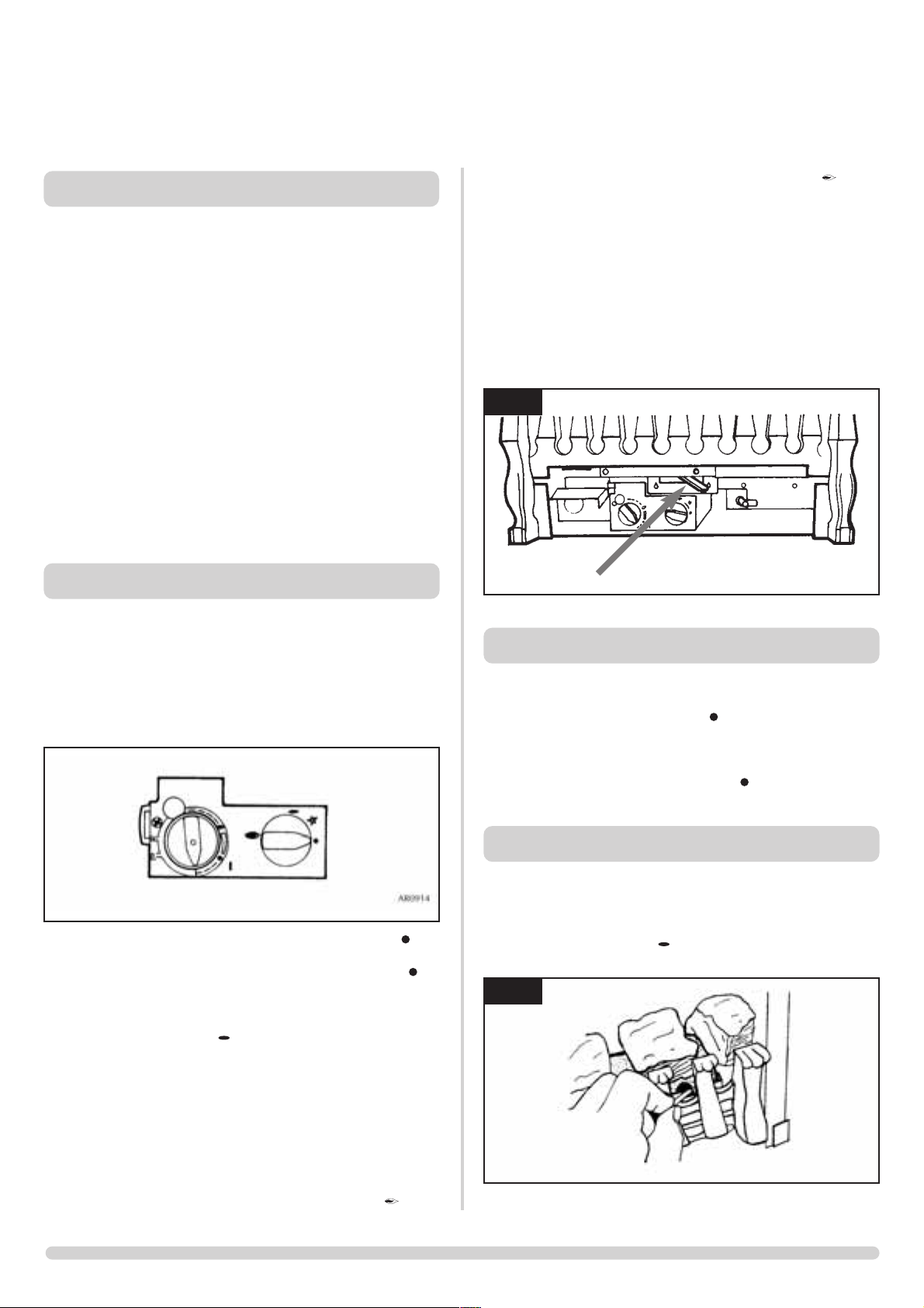
2.1 Locate the control valve on the appliance. There are two
control knobs on the valve: the right hand knob controls the
pilot ignition and the left hand knob controls the main burner.
2.2 If your appliance has already been upgraded to battery remote
control, please refer to the instructions provided with the
upgrade to operate the remote control. The following
instructions will work for either situation.
2.3 Ensure that the left-hand control knob is pointing to off ( ).
2.4 Ensure that the right hand control knob is pointing to off ( ).
2.5 Press in the right hand control knob and rotate it
anti-clockwise until a click is heard (keep pressing in) and the
knob is pointing to pilot ( ). The pilot should now light. If the
pilot has not lit, repeat the procedure until it does.
2.6 Keep the control knob pressed for 10 seconds and then
release it. The pilot should stay alight. If the pilot goes out,
repeat the procedures until it lights.
2.7 If the pilot will not light after repeated attempts, contact the
retailer or installer from whom the appliance was purchased.
2.8 Turn the right hand control to point to main burner ( ). The
appliance can now be controlled using the left hand control
knob.
2.9 Turn the left hand control knob to point to low fire ( ), the
main burner will light on low. The burner can now be
controlled between low and high settings. Turn the control
knob anticlockwise increase the flame height and clockwise to
decrease the flame height.
2.10 The flames can be varied from blue to a yellow effect by
moving the aeration lever to the desired position.
See diagram 1.
THE YELLOW FLAMES WILL APPEAR WHEN THE FIRE HAS
GAINED SUFFICIENT HEAT - TYPICALLY 10 TO 20
MINUTES.
3. TURNING THE FIRE OFF
3.1 To turn the fire off, locate the control valve, turn the left-hand
control knob until it points to off ( ). The main burner will go
out leaving the pilot burning.
3.2 To turn the pilot off, locate the control valve, turn the right
hand control knob until it points to off ( ). The pilot will go
out.
4. LIGHTING THE FIRE WITH A MATCH
If the pilot does not ignite as described in Section 2:
4.1 Press in the right hand control knob and rotate it
anti-clockwise until a click is heard (keep pressing in) and the
knob is pointing to pilot ( ), apply a lighted match to the
pilot hood, see diagram 2.
1. GENERAL
1
2
AR0416
AR0944
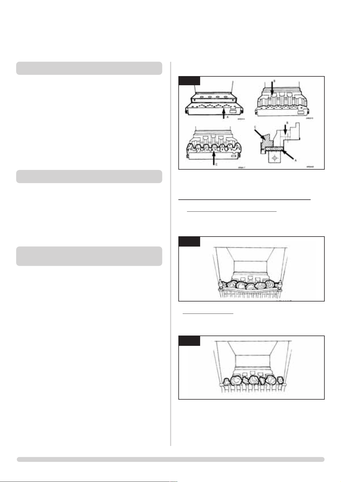
7.2 Position the front coal, make sure it sits flat onto the burner
skin. See diagram 3 arrow C.
7.3 Place the coals following the appropriate diagrams and
instructions
16” AND REDUCED DRAUGHT COAL LAYOUT
7.4 Curved fronts (Holyrood and Richmond) -place 5 large coals
onto the front coal moulding ensuing that they rest against
the front, place 2 small coals on to the front coal, 1 at each
end. See diagram 4.
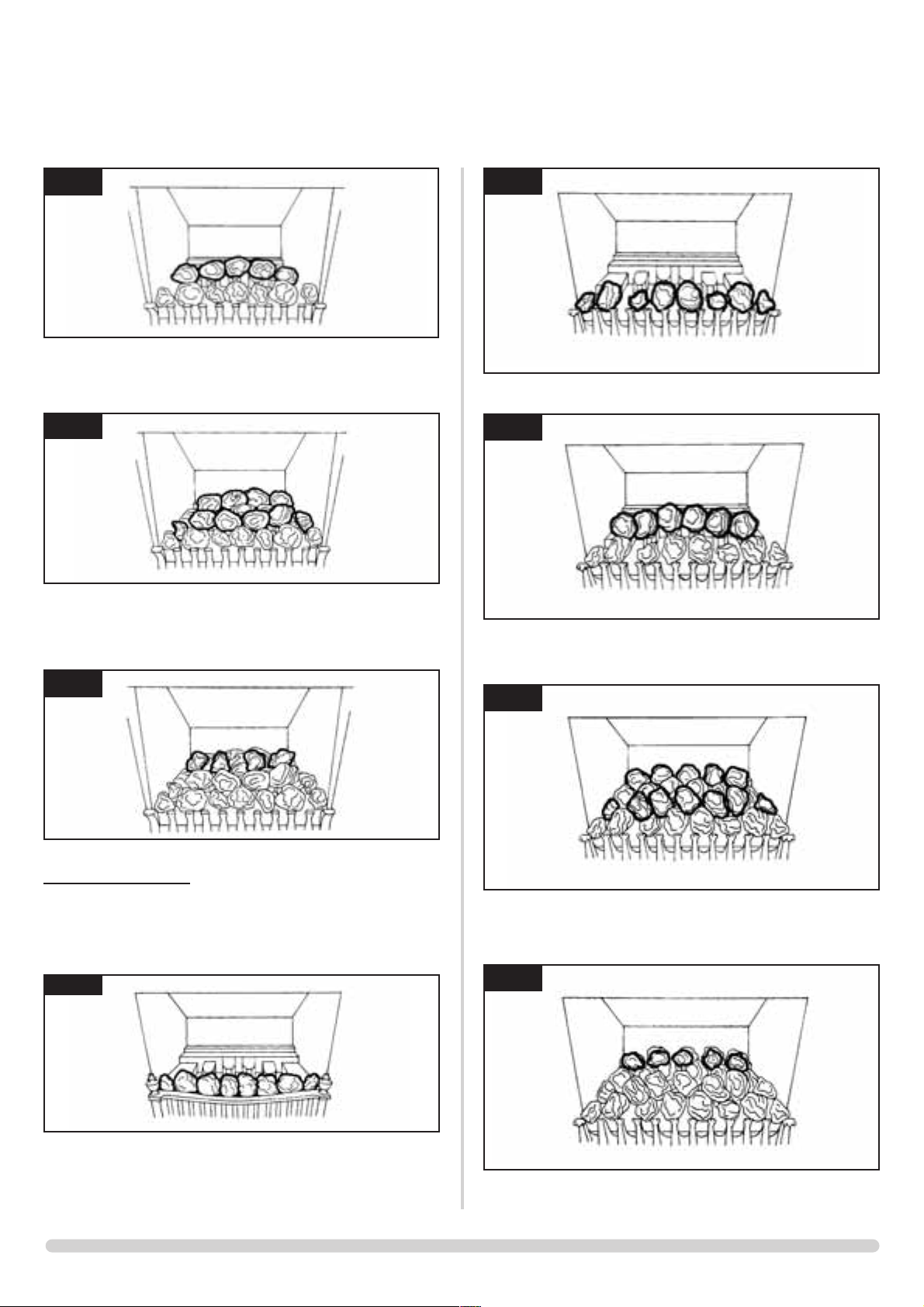
7.5 Flat fronts (All others)
- Place 3 large coals and 4 small coals
onto the front coal moulding ensuring that they rest against the
decorative front, these should run intermittently small, large,
small etc. See diagram 5.
7.6 Place 5 large coals onto the flame baffle fingers. See diagram 6.
5
USER INSTRUCTIONS
5. UPGRADING YOUR FIRE
5.1 Your fire is fitted with a control valve that can easily be
upgraded to battery powered remote control. This upgrade
can be fitted by anyone capable of simple DIY jobs and
requires no special training. This upgrade can be obtained
through your local Gazco stockist.
5.2 STANDARD REMOTE CONTROL This remote control can
control the fire after the pilot has been lit. It can turn the main
burner on and regulate it from low through to high and back
again. It can turn the main burner off leaving the pilot burning
GAZCO PART NUMBER 8455.
5.3 IMPORTANT - there is a thermostatic version of the upgrade
but this is NOT SUITABLE for open flame fires like the VFC.
6. CLEANING THE FIRE
6.1 Remove the ceramic coals and place on a dry, clean
surface. Remove the front coal ceramic, please handle with
care.
6.2 The ceramic parts should not require cleaning. Do not use a
vacuum cleaner or brush to clean these parts, any large pieces
of debris may be removed by hand.
6.3 Ensure any debris is removed from the burner ports.
6.4 Replace the ceramics by referring to Section 7.
7. ARRANGEMENT OF FUEL BED
COMPONENTS
ADVICE ON HANDLING AND DISPOSAL OF FIRE CERAMICS
The fuel effect and side panels in this appliance are made from
Refractory Ceramic Fibre (RCF), a material which is commonly
used for this application.
Protective clothing is not required when handling these articles,
but we recommend you follow normal hygiene rules of not
smoking, eating or drinking in the work area and always wash your
hands before eating or drinking.
To ensure that the release of RCF fibres are kept to a minimum,
during installation and servicing a HEPA filtered vacuum is
recommended to remove any dust accumulated in and around the
appliance before and after working on it. When servicing the
appliance it is recommended that the replaced items are not
broken up, but are sealed within heavy duty polythene bags and
labelled as RCF waste.
RCF waste is classed as stable, non-reactive hazardous waste and
may be disposed of at a licensed landfill site.
Excessive exposure to these materials may cause temporary
irritation to eyes, skin and respiratory tract; wash hands thoroughly
after handling the material.
NOTE: CERAMIC PARTS ARE FRAGILE. ONLY USE THE SPECIAL
CERAMIC COALS SUPPLIED BY GAZCO - DO NOT USE REAL
COALS.
7.1 Position the flame baffle on the rear of the tray. See diagram 3
arrow B.
3
4
5
AR1115
AR1116
7.11 Place 6 large coals onto the flame baffle fingers. See diagram 11.
7.12 Place 5 large coals so that they form a bridge between the
other 2 rows, and 2 small coals, 1 at each end. Place 5 large
coals at the back of the fire. See diagram 12.
7.13 Place the remaining 5 small coals on top of the others so that
they form a bridge between the second and third rows. See
diagram 13.
6
USER INSTRUCTIONS
7.7 Place 4 large coals so that they form a bridge between the
other 2 rows, and 2 small coals, 1 at each end. Place 4 large
coals at the back of the fire. See diagram 7.
7.8 Place the remaining 4 small coals on top of the others so that
they form a bridge between the second and third rows. See
diagram 8.
18” COAL LAYOUT
7.9 Curved fronts (Holyrood) - place 6 large coals onto the front
coal moulding ensuring that they rest against the front, place 2
small coals on to the front coal, 1 at each end. See diagram 9.
7.10 Flat fronts (All others) - Place 4 large coals and 4 small coals
onto the front coal moulding ensuring that they rest against the
decorative front, these should run intermittently small, large,
small, with 2 large in the centre. See diagram 10.
12
7
8
9
10
11
13
AR1118
AR1119
AR1120
AR1121
AR1122
AR1123
AR1124
6
AR1117
7
USER INSTRUCTIONS
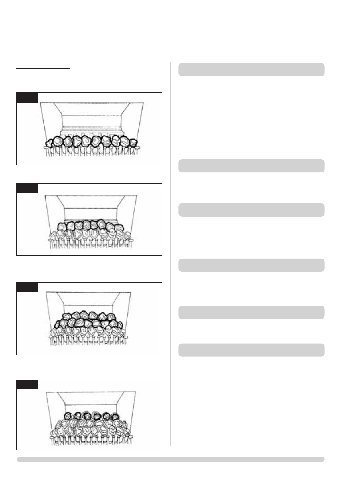
22” COAL LAYOUT
7.14 All fronts - place 8 large coals onto the front coal moulding
ensuring that they rest against the front, place 2 small coals on
to the front coal, 1 at each end. See diagram 14.
7.15 Place 8 large coals onto the flame baffle fingers. See
diagram 15.
7.16 Place 7 large coals so that they form a bridge between the
other 2 rows, and 2 small coals, 1 at each end. Place 6 large
coals at the back of the fire. See diagram 16.
7.17 Place the remaining 6 small coals on top of the others so
that they form a bridge between the second and third rows.
See diagram 17.
8. OXYGEN DEPLETION SENSOR
The appliance is fitted with an oxygen sensitive pilot system
will act to cut off the gas supply to the fire should the oxygen
in the room fall below its normal level.If the fire is turned off
by this device, it usually indicates that there is a problem with
the flue system, and this should be inspected by a qualified
engineer.
Do not attempt to use the fire until an engineer says it is
safe to do so.
This device is not a substitute for an independently
mounted carbon monoxide detector.
9. THE FLAME FAILURE DEVICE
This is a safety feature incorporated in all GAZCO fires which
automatically switches off the gas supply if the pilot light goes
out and fails to heat the thermocouple.
10.’RUNNING IN’
The surface coating on the coals used in your GAZCO fire will
‘burn off’ during the first few hours of use, producing a
harmless and temporary odour. This will disappear after a
short period of use. If the odour persists, ask your installer for
advice.
11.SERVICING
This fire must be serviced every 12 months by a qualified Gas
Engineer. In all correspondence, always quote the appliance
type and serial number, which may be found on the
databadge, adjacent to the control knob.
12.VENTILATION
Any purpose provided ventilation should be checked
periodically to ensure that it is free from obstruction.
13. INSTALLATION DETAILS
To assist in any future correspondence, your retailer should
have completed this commissioning sheet, this records, the
essential installation details of the appliance. In all
correspondence always quote the model No and serial No.
14
15
16
17
AR1126
AR1127
AR1128
AR1129
8
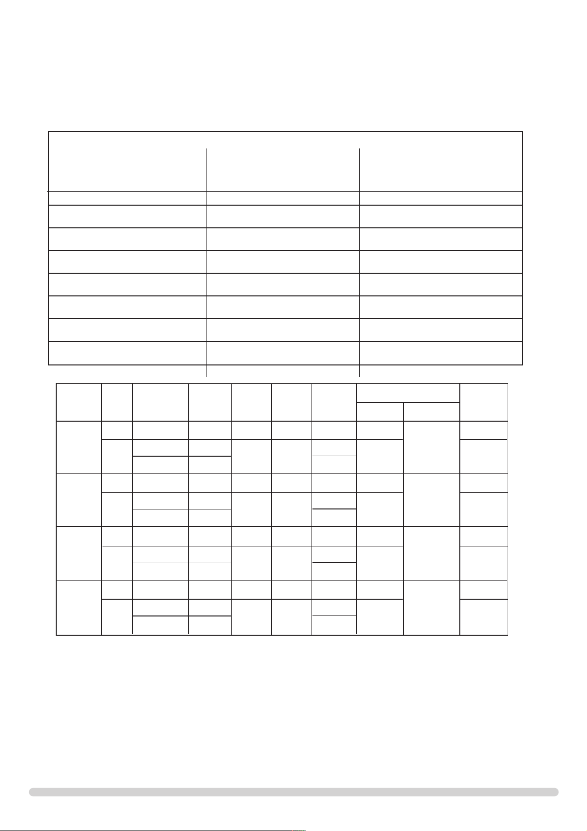
TECHNICAL SPECIFICATION
THESE INSTRUCTIONS COVER THE FOLLOWING MODELS:
VFC RADIANT VFC COVECTOR VFC LOW CONVECTOR
8300UC 16” 8420UC 16” 8461UC 16”LL
P8300UC 16” P8420UC 16” P8461UC 16”LL
8301UC 16”RD 8421UC 16”RD 8463UC 16”RD LL
P8301UC 16”RD P8421UC 16”RD P8463UC 16”RD LL
8305UC 18” 8425UC 18” 8466UC 18”LL
P8305UC 18” P8425UC 18” P8466UC 18”LL
8310UC 22” 8430UC 22” 8471UC 22”LL
P8310UC 22” P8430UC 22” P8471UC 22”LL
Model Gas Gas Working Aeration Injector Gas Rate Input kW (Gross) Country
CAT. Type Pressure m
3
/h
High
Max Flue
Temp.
I
2H
Natural(G20) 20mbar 12N 400 •653 GB,IE
Butane(G30) 29mbar •190
Propane(G31) 37mbar •250
6.85
RDL
I
3+
180
6.65
GB,IE
160°C
I
2H
Natural(G20) 20mbar 12N 600 •900 GB,IE
Butane(G30) 29mbar •272
Propane(G31) 37mbar •358
9.45
9L
I
3+
260
9.50
GB,IE
190°C
I
2H
Natural(G20) 20mbar 11N 700 1•010 GB,IE
Butane(G30) 29mbar •303
Propane(G31) 37mbar •399
10.60
9L
I
3+
300
10.60
GB,IE
200°C
I
2H
Natural(G20) 20mbar 9N 850 1•172 GB,IE
Butane(G30) 29mbar •363
Propane(G31) 37mbar •478
12.30
0L
I
3+
360
12.70
GB,IE
210°C
16 RD
16
18
22
MINIMUM FLUE SIZE 178mm (7”)
INLET CONNECTION SIZE 8mm
MIN FLUE SPECIFICATION T260/N2/0/D/1

9
The flue must be installed in accordance with all local and
national regulation and the current rules in force.
1.FLUE AND CHIMNEY REQUIREMENTS
1.1 The chimney or flue system must comply with the rules in
force, and must be a minimum of 178mm (7î) in diameter.
1.2 The minimum effective height of the flue or chimney must be
3 m (10ft).
1.3 The chimney or flue must be free from any obstruction. Any
damper plates should be removed or secured in the fully open
position, and no restrictor plates should be fitted.
1.4 The chimney should be swept immediately prior to the
installation of the appliance - unless it can be seen to be clean
and unobstructed throughout its entire length.
1.5 Ensure that there is a smooth taper transition from the
fireplace opening into the chimney or flue.
1.6 The flue pull should be checked prior to installation of the
appliance. Apply a smoke pellet to the flue or chimney
opening and ensure that the smoke is drawn into the opening.
If there is not a definite flow, pre-heat the chimney for a few
minutes and re-test the flow.
IF THERE IS STILL NO DEFINITE FLOW, THE CHIMNEY
MAY REQUIRE ATTENTION- SEEK EXPERT ADVICE.
2. INSTALLATION OF THE GAS SUPPLY
2.1 Before installation, ensure that the local distribution
conditions (identification of the type of gas and pressure) and
the adjustment of the appliance are compatible.
2.2 Ensure that the gas supply is capable of delivering the
required amount of gas, and is in accordance with the rules in
force.
2.3 Soft copper tubing and soft soldered joints can be used but
must not be closer than 50mm (2”) to the underside of the
firebox.
2.4 A means of isolating the gas supply to the appliance must be
provided independent of any appliance control.
2.5 All supply gas pipes must be purged of any debris that may
have entered, prior to connection to the appliance.
3. VENTILATION
It is important to ensure that any national ventilation
requirements are taken into account during the installation of
this appliance.
3.1 Ventilation requirements differ according to the model.
Minimum permanent effective free air requirements - if this is
the sole gas appliance in the room - are as follows:
Model No. Description Min. vent cm2
8300UC, P8300UC 16” VFC Radiant
8305UC, P8305UC 18” VFC Radiant 100 See note b.
8310UC, P8310UC 22” VFC Radiant
8301UC, P8301UC RD VFC Radiant NONE
8421UC, P8421UC RD VFC NONE
8463UC, P8463UC Convector See notes a & b
8420UC, P8420UC 16” VFC 15
8461UC, P8461UC Convector
8425UC, P8425UC 18” VFC 20
8466UC, P8466UC Convector
8430UC, P8430UC 22” VFC 30
8471UC, P8471UC Convector See note b
Note a:
Gas input is less than 7kW and flue products clearance under 70
m3/hr. Some countries call for 100cm2 ventilation. Check local
standards.
Note b:
It is essential to check for flue clearance (see diagrams 17/18) If
spillage is detected, it may be necessary to provide additional
ventilation.
3.2 The above table is in addition to any openable window, and
although it must communicate with the outside air, wherever
possible, it can communicate with an adjacent room provided
that the space has a similar vent to the outside.
AIR VENTS MUST NOT BE RESTRICTED.
4. APPLIANCE LOCATION
4.1 This appliance must stand on a non-combustible hearth that is
at least 12mm thick.
4.2 It must be fitted into a non-combustible opening.
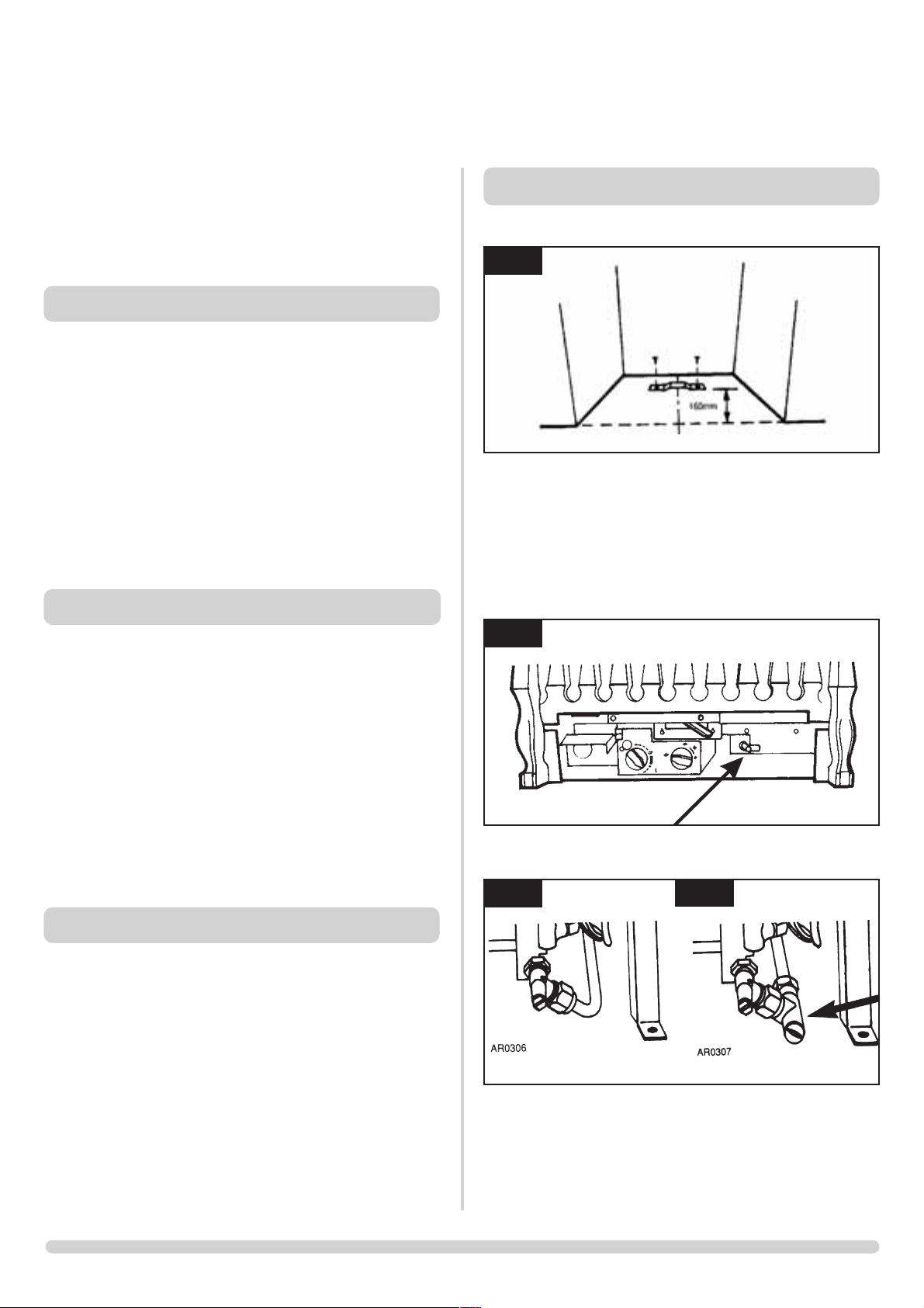
4.3 These appliances must be hearth mounted into a fireplace
opening conforming to National Standards. The minimum
dimensions shall be as shown in diagram 1A for VFC Radiant
fires or diagram 1B for VFC Convector fires. (The shaded area
must be flat and square).
INSTALLATION INSTRUCTIONS
SITE REQUIREMENTS
1A

10
4.4 The appliance must be firmly fixed to the hearth. Fasteners are
provided for this purpose.
4.5 Ensure that no naked flame or incandescent part of the fire
bed projects beyond the vertical plane of the fireplace
opening.
4.6 The appliance must not be installed in any room that contains
a bath or shower.
4.7 Ensure clearances to combustible materials - see diagram 2.
INSTALLATION INSTRUCTIONS
SITE REQUIREMENTS
2
1B
4. INSTALLATION - RADIANT FIRES
4.1 Fix the rear leg strap. See diagram 1.
4.2 Position the fire with the rear leg fully engaged under the rear
leg strap. Fasten the front legs using the fixings supplied.
4.3 “HAVE YOU PURGED THE GAS SUPPLY PIPES”. This is
essential to expel any foreign matter that might get blown into
the valve assembly causing blockages.
4.4 Connect the 8mm gas supply pipe to the fire. See diagram 2& 3.
4.5 If the isolation tap is to be fitted under the fire, the GAZCO
GC0060 provides a neat and easy solution. See diagram 3A.
4.6 Check the gas connections to the fire are sound. Light the fire
and check all joints on the appliance.
4.7 Check the appliance running pressure is correct. See
databadge.
11
IMPORTANT: ENSURE THAT THE APPLIANCE IS
CORRECTLY ADJUSTED FOR THE GAS TYPE AND
CATEGORY APPLICABLE IN THE COUNTRY OF USE. REFER
TO DATABADGE AND TECHNICAL SPECIFICATIONS AT
THE FRONT OF THE BOOKLET. FOR DETAILS OF
CHANGING BETWEEN GAS TYPES, REFER TO SECTION 33.
1. CONTROL UPGRADE
1.1 Your fire is fitted with a control valve that can be easily
upgraded to battery powered remote control. This upgrade
can be fitted by anyone capable of simple DIY jobs and
requires no special training. This upgrade can be obtained
through your local Gazco stockist.
1.2 STANDARD REMOTE CONTROL This remote control can
control the fire after the pilot has been lit. It can turn the main
burner on and regulate it from low through to high and back
again. It can turn the main burner off leaving the pilot burning.
GAZCO PART NUMBER 8455.
1.3 IMPORTANT - there is a thermostatic version of the upgrade
but this is NOT SUITABLE for open flame fires.
2. SAFETY PRECAUTIONS
2.1 This appliance must be installed in accordance with the rules
in force, and used only in a sufficiently ventilated space. Place
read all instructions before installation and use of this
appliance.
2.2 These instructions must be left intact with the user.
2.3 Do not attempt to burn rubbish on this appliance.
2.4 In your own interest, and those of safety, this appliance must
be installed by a competent person in accordance with local
and national codes of practice. Failure to install the appliance
correctly could lead to prosecution.
2.5 Keep all plastic bags away from young children.
3. UNPACKING
3.1 Remove the appliance from its packaging, and check that it is
complete and undamaged.
3.2 Put the loose ceramic parts to one side so that they are not
damaged during installation.
INSTALLATION INSTRUCTIONS
INSTALLATION
1
2
3
3A
AR0019
AR0944

12
4.8 Fit the fret to the fire front using two screws. See diagram 4.
5. INSTALLATION - CONVECTOR FIRES
5.1 Make any necessary alterations to fireplace opening. Ensure
that the lintel does not obstruct the flue outlet into the flue,
and that there is a clear space for debris of at least 90mm. See
diagram 5.
5.2 Gas pipe entry must be through one of the holes in the rear
of the convector box. See diagram 6 & 7.
Note: Gas pipes passing through masonry must be protected.
5.3 If the isolation tap is to be fitted under the fire, the GAZCO
GC0060 provides a neat and easy solution. See diagram 7A.
5.4 Remove the fire assembly (see diagram 9), and offer the
convector box into the opening, checking that it fits squarely.
Mark the fixing holes and the gas pipe entry positions. See
diagram 8.
5.5 Fit the gas pipe into position, ready for passing into the
convector box, ensuring enough remains to connect to the
fire.
5.6 Carefully fit the convector box, feeding the piping through into
the box. Secure the box to the wall, through the flange or base
ensuring that the box is square in the opening. Any
undulations or gaps between the convector box and the wall
should be filled with a non-combustible material. Do not use
silicone as it makes future removal almost impossible.
5.7 Refit the fire assembly and front air guide back into the
convector box. See diagram 9.
5.8 HAVE YOU PURGED THE GAS SUPPLY PIPES.
This is essential to expel any foreign matter that might get
blown into the valve assembly causing blockages.
INSTALLATION INSTRUCTIONS
INSTALLATION
4
5
6
7
7A
8
AR0311
AR0300
AR0200
AR0313
AR0314
9
Protective clothing is not required when handling these articles,
but we recommend you follow normal hygiene rules of not
smoking, eating or drinking in the work area and always wash your
hands before eating or drinking.
To ensure that the release of RCF fibres are kept to a minimum,
during installation and servicing a HEPA filtered vacuum is
recommended to remove any dust accumulated in and around the
appliance before and after working on it. When servicing the
appliance it is recommended that the replaced items are not
broken up, but are sealed within heavy duty polythene bags and
labelled as RCF waste.
RCF waste is classed as stable, non-reactive hazardous waste and
may be disposed of at a licensed landfill site.
Excessive exposure to these materials may cause temporary
irritation to eyes, skin and respiratory tract; wash hands thoroughly
after handling the material.
NOTE: CERAMIC PARTS ARE FRAGILE.
6.1 Position the flame baffle on the rear of the tray. See diagram
13 arrow B.
6.2 Position the front coal, make sure it sits flat onto the burner
skin. See diagram 13 arrow C.
6.3 Place the coals following the appropriate diagrams and
instructions
16” AND REDUCED DRAUGHT COAL LAYOUT
6.4 Curved fronts (Holyrood and Richmond) -place 5 large coals
onto the front coal moulding ensuing that they rest against
the front, place 2 small coals on to the front coal, 1 at each
end. See diagram 14.
13
10
11
12
INSTALLATION INSTRUCTIONS
INSTALLATION
13
14
AR0944
AR0303
AR0311
5.9 Connect the 8mm gas supply pipe to the fire. See diagram 10.
5.10 Check the gas connections to the fire are sound. Light the fire
and check all joints on the appliance.
5.11 Check the appliance working pressure is correct. See
databadge.
5.12 Fit the fire trim to the convector box. See diagram 11.
5.13 Fit the fret to the fire front using the two securing screws. See
diagram 12.
5.14 If the appliance is fitted with an alternative Gazco front
please refer to the separate leaflet supplied with the front.
6. ARRANGEMENT OF FUELBED
COMPONENTS
ADVICE ON HANDLING AND DISPOSAL OF FIRE CERAMICS
The fuel effect and side panels in this appliance are made from
Refractory Ceramic Fibre (RCF), a material which is commonly
used for this application.

14
6.5 Flat fronts (All others) - Place 3 large coals and 4 small coals
onto the front coal moulding ensuring that they rest against the
decorative front, these should run intermittently small, large,
small etc. See diagram 15.
6.6 Place 5 large coals onto the flame baffle fingers. See
diagram 16.
6.7 Place 4 large coals so that they form a bridge between the
other 2 rows, and 2 small coals, 1 at each end. Place 4 large
coals at the back of the fire. See diagram 17.
6.8 Place the remaining 4 small coals on top of the others so that
they form a bridge between the second and third rows. See
diagram 18.
6.10 Flat
fronts (All others) - Place 4 large coals and 4 small coals
onto the front coal moulding ensuring that they rest against the
decorative front, these should run intermittently small, large,
small, with 2 large in the centre. See diagram 20.
6.11 Place 6 large coals onto the flame baffle fingers. See diagram 21.
INSTALLATION INSTRUCTIONS
INSTALLATION
16
17
18
19
20
21
AR1117
AR1118
AR1119
AR1120
AR1121
AR1122
18” COAL LAYOUT
6.9 Curved fronts (Holyrood) - place 6 large coals onto the front
coal moulding ensuring that they rest against the front, place 2
small coals on to the front coal, 1 at each end. See diagram
19.
15
AR1116

15
5.13 Place the remaining 5 small coals on top of the others so that
they form a bridge between the second and third rows. See
diagram 23.
22” COAL LAYOUT
5.14 All fronts
- place 8 large coals onto the front coal moulding
ensuring that they rest against the front, place 2 small coals on
to the front coal, 1 at each end. See diagram 24.
5.16 Place 7 large coals so that they form a bridge between the
other 2 rows, and 2 small coals, 1 at each end. Place 6 large
coals at the back of the fire. See diagram 26.
6.17 Place the remaining 6 small coals on top of the others so
that they form a bridge between the second and third rows.
See diagram 27.
7. LIGHTING
7.1 Full instructions are given in the Users Section.
INSTALLATION INSTRUCTIONS
INSTALLATION
23
24
25
26
27
AR1124
AR1126
AR1127
AR1128
22
AR1123
5.15 Place 8 large coals onto the flame baffle fingers. See
diagram 25.
6.12 Place 5 large coals so that they form a bridge between the
other 2 rows, and 2 small coals, 1 at each end. Place 5 large
coals at the back of the fire. See diagram 22.
AR1129

16
1. COMMISSIONING
1.1 Close all windows and doors to the room, check all controls,
and allow fire to burn on maximum for 5 minutes. Test for
spillage of flue products using a smoke match. For standard
VFC fires, pass the lighted smoke match along the top front
edge just inside the opening or canopy. For the RD VFC only,
hold the lighted smoke match centrally inside the flue
opening. See diagram 1 for Radiant fires and 2 for Convector
fires.
1.2 If the fire spills, run for a further 10 minutes and re-check. If
there is still spillage, disconnect the fire and seek expert
advice.
1.3 If there are extractor fans in the room or adjacent rooms, the
spillage test must be repeated with the extractors running on
maximum.
1.4 For RD VFC: If spillage is detected and no air vent is fitted in
the room, re-check for spillage with a window slightly open. If
this cures the spillage, it will be necessary to fit a vent.
IF SPILLAGE PERSISTS, DISCONNECT THE APPLIANCE AND
SEEK EXPERT ADVICE.
For future reference record the installation details on the
commissioning sheet on page 4 of these instructions.
INSTALLATION INSTRUCTIONS
COMMISSIONING
1
2
AR0187
AR0179

17
This appliance must be serviced at least one a year by a
competent person.
1. SERVICING REQUIREMENTS
1.1 As part of the annual service, the space behind the convector
must be inspected for any debris, which may have fallen down
the chimney.
1.2 Remove the gas fire from the convector as detailed in section 4
1.3 Remove the convector box from the wall, see section 5 in
Installation.
1.3 Inspect the space behind the convector for debris and the
condition of the chimney, the flue flow test should be carried
out now. Remove any debris and carry out any necessary
remedial work.
This is for use only by qualified Installers and Service Engineers.
Note: Many problems can be attributed to poor pilot flame length
caused by blocked jets as the orifice is very small. If the flame
length is much shorter than that shown in the diagram, the pilot
may have to be changed. See diagram 7.
It is always worth using the nozzle of a vacuum cleaner over the
end of the pilot to ensure that it has no debris within it. In
addition, many ignition problems are caused by incorrect spark
gap, ensure it is set as in diagram 7.
INSTALLATION INSTRUCTIONS
SERVICING REQUIREMENTS
2. FAULT FINDING
FLAME FAILURE FUNCTIONAL CHECK
PILOT WILL NOT STAY LIT OR FIRE GOES OUT
If the appliance goes out in use continually, this may mean
that the
oxygen depletion sensor has been activated. The appliance
should not be used
until the cause has been found and rectified.
Ensure there is no debris around the pilot assembly, e.g.
coal, soot, etc.
Check for fluff in the pilot aeration hole. See diagram 7.
Light the pilot and keep the control knob pushed in at least
10 seconds before letting go
With the pilot
running is the
gas pressure
as
stated on the
databadge?
Is the pilot
flame of the
correct
length?
See diagram
7.
Is
thermocouple
connection
good
in back of
valve
Replace
ODS unit
Change the
ODS unit
SYSTEM O.K
Tighten the
connection
and retry
With the fire
running on
full is
the gas at the
pressure
stated
on the
databadge
Problem is
with
the pipework
or
fittings which
lead to the
fire. Correct
and retry
Run for 60
sec’s.,
turn off, time
interval until
mag unit
shuts with a
click. Is this
greater
than 7
seconds?
Run for 60
sec’s.,
turn off, time
interval until
mag unit
shuts with a
click. Is this
greater
than 7
seconds?
Will the pilot
stay lit?
Will the pilot
stay lit?
Change
mag unit
YES
NO
NO
NO
NO
NO
NO
NO
NO
NO
YES
YES
YES
YES
YES
7

18
FAULT FINDING
IGNITION FUNCTIONAL CHECK 1
PILOT WILL NOT LIGHT
Ensure there is no debris around the pilot assembly, e.g coal, soot, etc which
could short the spark, clean the area. Check for fluff in the pilot aeration hole.
See diagram 7, arrow A.
There is a blockage in the system, check the inlet test point, the mag
seating, valve and pilot filter.
Operate the valve.
Is there a spark?
Consult users book
and retry
Ensure gap between the
electrode & thermocouple is
as Dia. 7 & retry. If gap is OK
then first change the
ignition lead & retry, if still no
good then change gas valve
Is the control being operated
correctly?
Will the pilot light with a
match
Is the gas turned on to the
appliance?
Check isolation tap and
gas meter, retry
Purge the gas pipes
and retry
See “NO SPARK” chart*
System OK
Is the gas pressure
correct?
Has the system got any
air in it?
Does the pilot light?
Correct and retry
YES
YES
YES
YES
YES
NO
NO
NO
NO
NO
NO
NO
YES
YES
IGNITION FUNCTIONAL CHECK 2
NO SPARK
Ensure there is no debris around the pilot assembly, e.g coal, soot, etc which
could short the spark, clean the area.
Consult users
instructions, retry
Operate the valve.
Light the pilot, does the
valve click?
Is the gap between the
electrode & thermocouple as
in Dia. 7?
Is the control being operated
correctly?
Reset the pilot burner
Correct and retry
Has ignition lead become
detached or is connection
poor?
Replace the ODS unit
Replace the electrode lead
and retry
Replace the gas valve and retry
Check for defective or
damaged control knob
spindle or cam operation.
Check for correct location of
piezo components.
Correct and retry
Remove the electrode lead
from the piezo. Operate the
valve. Does a spark jump
from the piezo to the valve
body?
Remove the electrode lead
from electrode with insulated
pliers hold the tip 3.5mm
from the pilot pipework, is
there a spark when the valve
‘clicks’?
Is the electrode wire
detached from the piezo in
the valve?
Replace the gas valve, retry
YES
YES
NO
NO
*
NO
NO
YES
YES
YES

19
INSTALLATION INSTRUCTIONS
REPLACING PARTS
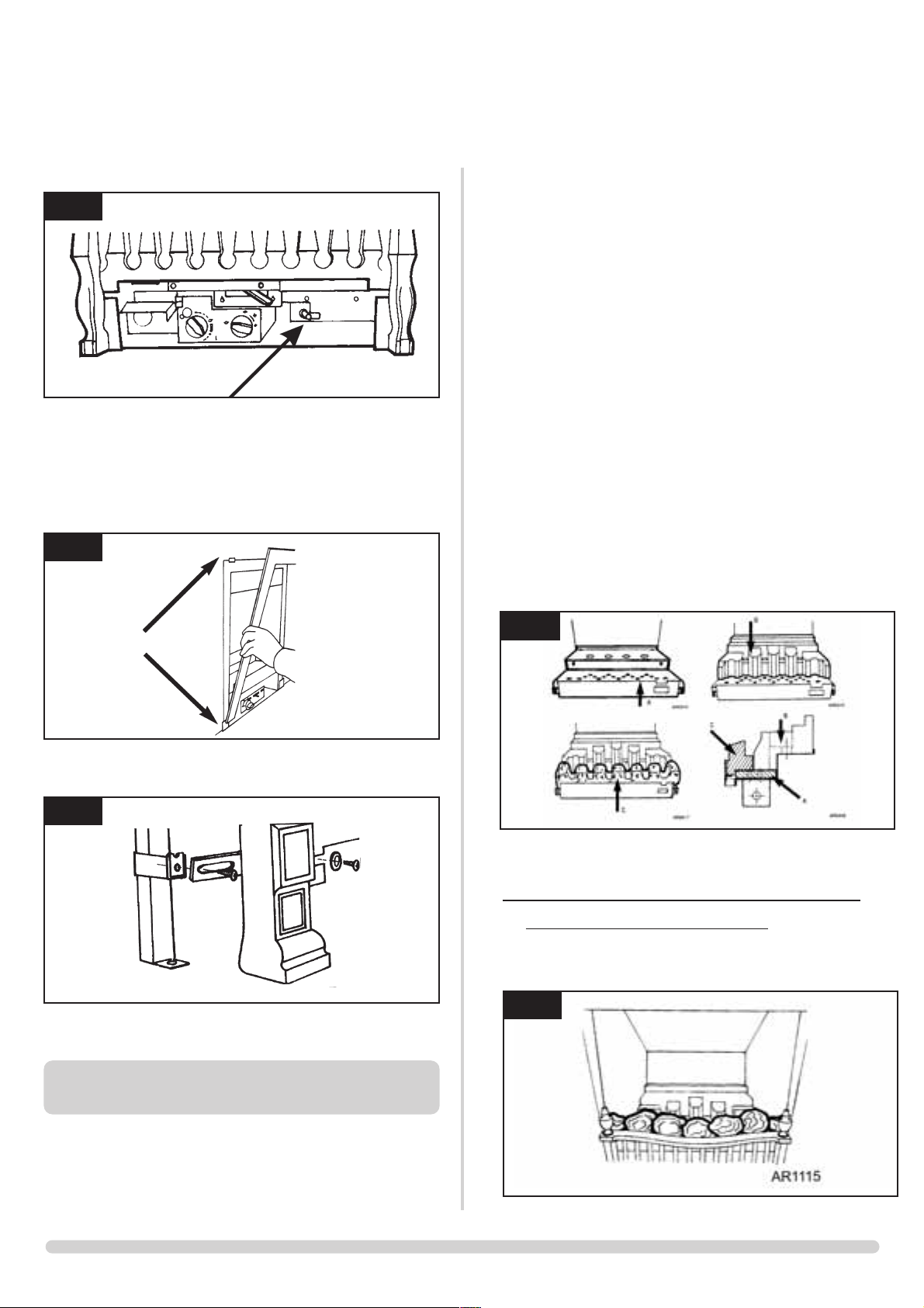
2. IGNITION LEAD
The following part can be serviced without removing the
fire.
2.1 Turn off the gas supply at the isolation device.
2.2 Remove the fret. See diagram 1.
2.3 Undo the single screw that secures the left hand side of the
control cover. See diagram 2.
2.4 To release the right hand side of the control cover insert the
narrow blade screwdriver into the slot shown in diagram 3,
lever it gently and pull from the right hand side at the same
time. The cover will now come off, there is a small cylindrical
metal spacer inside the cover, this must be kept and replaced
on the fixing screw during re-assembly.
2.5 Disconnect the ignition lead from the gas valve and the pilot.
See diagram 4 arrow A.
1
3
4
AR0916
AR0305
2.6 Replace with a new ignition lead following the same route as
the old one. Replace the valve cover and the pilot assembly.
2.7 Check the operation of the new ignition lead.
2.8 Replace the fret.
3. PIEZO
3.1 The piezo assembly used on this appliance is not serviceable
and is unlikely to fail.
4. THE FOLLOWING PARTS REQUIRE THE
REMOVAL OF THE BURNER FROM THE
CONVECTOR BOX .
a) Turn the gas supply off at the isolation device.
b) Disconnect the gas supply pipe from the pressure test
elbow on the appliance.
c) Undo the screws securing the fire. See diagram AR0314.
d) Remove the fire for servicing.

20
5. ODS PILOT UNIT
Note: The pilot unit on the appliance is a non serviceable unit due
to the complex nature of its manufacture. Replacement of the
complete unit must be carried out when one of the following
items becomes faulty:
Pilot injector
Ignition electrode
Thermocouple
5.1 Carry out operations (a) to (d), section 4.
5.2 Gently pull the ignition lead off the electrode. See diagram 5
arrow A.
5.3 Remove the two screws securing the pilot assembly. See
diagram 5 arrow B.
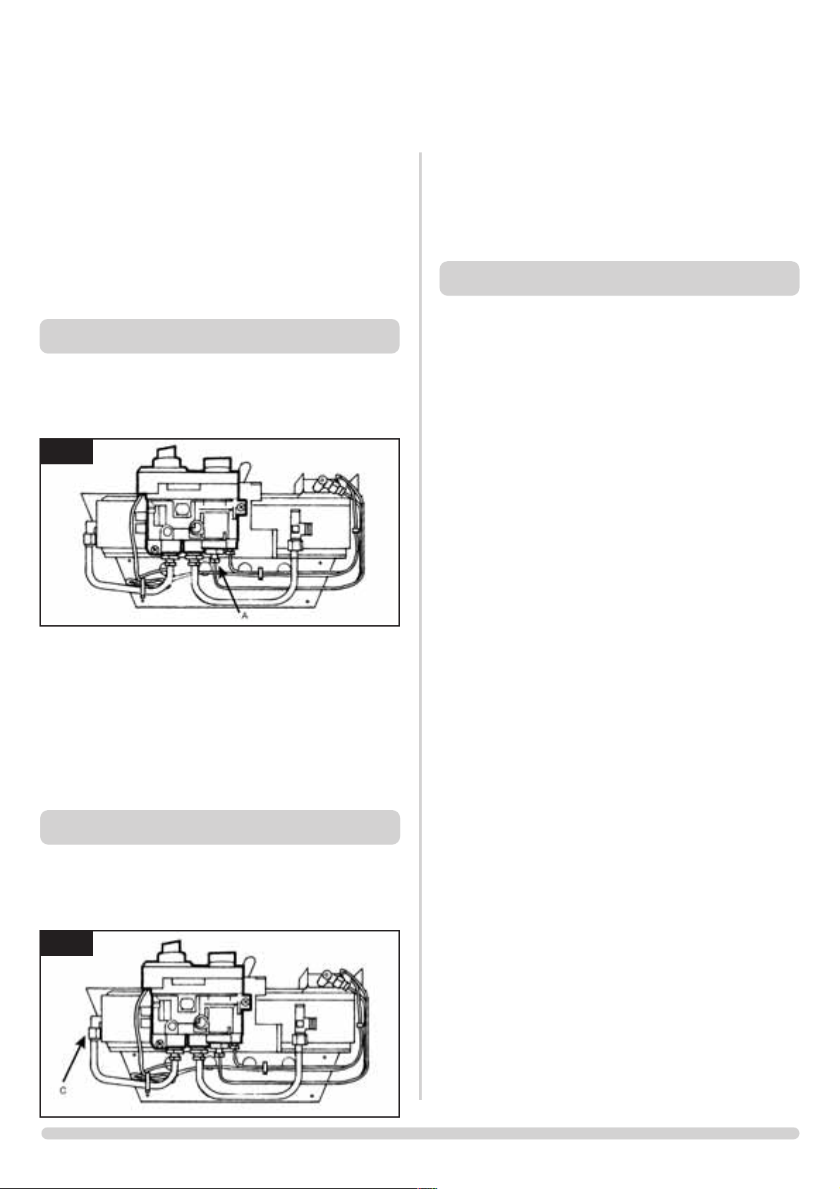
5.4 Undo the thermocouple connection at the back of the gas
valve. See diagram 6 arrow A.
5.5 Replace with a new pilot assembly, set the spark gap. See
diagram 7.
5.6 After reassembly, check for gas soundness and carry out a
flame failure functional check details in the flow chart,
especially the mag drop out time.
6. GAS VALVE
6.1 Turn the gas supply off at the isolation device.
6.2 Disconnect the 2x8mm and 1x4mm gas pipe fittings at the
back of the gas valve and also disconnect the thermocouple,
see diagram 8 arrow B.
6.3 Undo the single screw that secures the left hand side of the
control cover, see diagram 9.
6.4 To release the right hand side of the control cover insert the
narrow blade screwdriver into the slot shown in diagram 10,
lever it gently and pull from the right hand side at the same
time. The cover will now come off, there is a small cylindrical
metal spacer inside the cover, this must be kept and replaced
on the fixing screw during re-assembly.
INSTALLATION INSTRUCTIONS
REPLACING PARTS
5
8
9
10
6
7
AR0305
AR0945
AR0097
AR0915
AR0916
AR0945
21
6.5 Disconnect the ignition lead from the gas valve, refer to
section 27.
6.6 Undo the two bolts securing the gas valve to the appliance and
remove the valve.
6.7 Replace in reverse order.
6.8 Check all joints for gas leaks, check operation of the
thermocouple and ignition lead.
8. MAG UNIT
7.1 Carry out operations (a) to (d), section 4.
7.2 Undo the mag unit retaining nut at the back of the control
valve. See diagram 11 arrow A.
7.3 After removing the retaining nut, the mag unit can be tapped
out and a replacement fitted.
7.4 Replace the mag unit retaining nut and tighten. Note - this is a
gas-tight seal.
7.5 Replace the thermocouple and check for gas leaks.
7.6 After reassembly, carry out the flame failure functional check
as detailed in the flow chart, especially the mag unit drop out
time.
9. MAIN INJECTOR
8.1 Carry out operations (a) to (d), section 4.
8.2 With the fire removed, undo the injector compression
nut (see diagram 6 arrow C), pull the pipe clear of the injector
body.
8.3 Rotate the injector until it is fully removed.
8.4 Replace with the correct replacement injector. When ordering,
always state the model, gas type and serial number.
8.5 Reassemble and turn the gas supply on, check for any leaks
10. CHANGING BETWEEN GAS TYPES
The following parts must be changed when converting an
appliance from one gas type to another:
• Main injector
• Pilot assembly
• Aeration adjuster
• Control valve
• Data Badge
Refer to Gazco for a Conversion Kit
Note: The control valve will be set for the particular Appliance. In
addition a new databadge will need to be ordered. In all instances,
when ordering new parts, be sure to quote the appliance type and
serial number.
Use only genuine Gazco replacement parts. Non-standard
components will invalidate the guarantee and may be
dangerous.
11
6
INSTALLATION INSTRUCTIONS
REPLACING PARTS
AR0945
AR0945

MANUAL FIRES RD 16 18 22
CERAMIC PARTS
Front Coal LH CE0151 CE0152 CEO153/54
Flame Baffle CE0119 CE0120 CEO121
Burner Skin CE0155 CE0156 CEO157
Coal Set CE0394 CE0395 CEO396
Convector Side Cheek LH CEO158
Low Convector Side Cheek LH CEO160
Convector Side Cheek RH CEO159
Low Convector Side Cheek RH CEO161
NATURAL GAS PARTS
Main Injector IN0007 IN0005 IN0043 IN0042
Pilot Assembly PI0036 PI0044
Aeration Adjuster GZ3461 GZ3463 GZ3464
Gas Valve GC0088 - Preset for Nat. Gas*
LPG GAS PARTS
Main Injector IN0025 IN0001 IN0002 IN0023
Pilot Assembly PI0037 PI0045
Aeration Adjuster GZ3465 GZ3466 GZ3467
Gas Valve GC0088 - Preset for LPG Gas*
MISCELLANEOUS
Ignition Lead GC0090
Mag Unit GC0092
Control Cover GC0087
Upgrade Kit 8455
22
SPARES PARTS LIST
SPARES PARTS LISTS
*Please note: The gas value is factory preset-please consult Gazco for advise stating the model number and gas type.

23
SERVICE RECORDS
1ST SERVICE
Date of Service:...........................................................................
Next Service Due:.......................................................................
Signed:........................................................................................
3RD SERVICE
Date of Service:...........................................................................
Next ServiceDue:........................................................................
Signed:........................................................................................
5TH SERVICE
Date of Service:...........................................................................
Next Service Due:.......................................................................
Signed:........................................................................................
7TH SERVICE
Date of Service:...........................................................................
Next Service Due:.......................................................................
Signed:........................................................................................
.
9TH SERVICE
Date of Service:...........................................................................
Next Due:........................................................................
Signed:........................................................................................
2ND SERVICE
Date of Service:...........................................................................
Next Service Due:.......................................................................
Signed:........................................................................................
4TH SERVICE
Date of Service:...........................................................................
Next Service Due:.......................................................................
Signed:........................................................................................
6TH SERVICE
Date ofService:............................................................................
Next Service Due:.......................................................................
Signed:........................................................................................
8TH SERVICE
Date of Service:...........................................................................
Next Due:........................................................................
Signed:........................................................................................
10TH SERVICE
Date of Service:...........................................................................
Next Service Due:.......................................................................
Signed:........................................................................................

Gazco Limited, Osprey Road, Sowton Industrial Estate, Exeter, Devon, England EX2 7JG
Tel: (01392) 261999 Fax: (01392) 444148 E-mail: info@gazco.com
A member of the Stovax Group
 Loading...