


StorageWorks
SH043-SeriesCabinet
InstallationandUser’sGuide
Order Number: EK–SH043–IG. A01
This manual describes the concepts and procedures necessary to
install, configure, and use StorageWorks SH043-series cabinets. Both
mechanical cabinet configuration and power configuration are covered in
this manual. The configuration and connection of SCSI–2 signal busses
is covered in referenced StorageWorks documentation.
Digital Equipment Corporation
Maynard, Massachusetts

First Printing, October 1993
While Digital believes the information included in this publication is correct as of the date of
publication, it is subject to change without notice.
Digital Equipment Corporation makes no representations that the interconnection of its products
in the manner described in this document will not infringe existing or future patent rights, nor
do the descriptions contained in this document imply the granting of licenses to make, use, or sell
equipment or software in accordance with the description.
© Digital Equipment Corporation 1993.
All rights reserved.
Printed in the United States of America.
NOTE: This equipment generates, uses, and may emit radio frequency energy. The equipment has
been type tested and found to comply with the limits for a Class A digital device persuant to Part
15 of the FCC rules. These limits are designed to provide reasonable protection against harmful
interference in a residential installation.
Any changes or modifications made to this equipment may void the user’s authority to operate the
equipment.
Operation of this equipment in a residential area may cause interference in which case the user
at his own expense will be required to take whatever measures may be required to correct the
interference.
StorageWorks, CI, and the DIGITAL logo are trademarks of Digital Equipment Corporation.
This document was prepared using VAX DOCUMENT Version 2.1.

Contents
Preface . . . . . . . . . . . . . . . . . . . . . . . . . . . . . . . . . . . . . . . . . . . . . . . . . . . . . . . . . . . . vii
Manufacturer’s Declarations . . . . . . . . . . . . . . . . . . . . . . . . . . . . . . . . . . . . . . . . . xiii
1 Introduction
1.1 Overview . . . . . . . . . . . . . . . . . . . . . . . . . . . . . . . . . . . . . . . . . . . . . . . . . . 1–1
1.2 Major Components . . . . . . . . . . . . . . . . . . . . . . . . . . . . . . . . . . . . . . . . . . . 1–4
1.3 Power Configurations . . . . . . . . . . . . . . . . . . . . . . . . . . . . . . . . . . . . . . . . . 1–7
1.3.1 Single Cabinet Power Configuration . . . . . . . . . . . . . . . . . . . . . . . . . . 1–7
1.3.2 Dual Shelf Power Configuration . . . . . . . . . . . . . . . . . . . . . . . . . . . . . . 1–8
1.3.3 Dual Cabinet Power Configuration . . . . . . . . . . . . . . . . . . . . . . . . . . . 1–9
1.4 Cabinet Cooling System . . . . . . . . . . . . . . . . . . . . . . . . . . . . . . . . . . . . . . . 1–10
2 Site Preparation
2.1 General Considerations . . . . . . . . . . . . . . . . . . . . . . . . . . . . . . . . . . . . . . . 2–1
2.2 Equipment Grounding . . . . . . . . . . . . . . . . . . . . . . . . . . . . . . . . . . . . . . . . 2–2
3 Unpacking and Installation
3.1 Unpacking the Cabinet . . . . . . . . . . . . . . . . . . . . . . . . . . . . . . . . . . . . . . . 3–1
3.2 Removing the Cabinet from the Pallet . . . . . . . . . . . . . . . . . . . . . . . . . . . . 3–3
3.3 Configuring the Cabinet Rack Space . . . . . . . . . . . . . . . . . . . . . . . . . . . . . 3–6
3.4 Placing the Cabinet . . . . . . . . . . . . . . . . . . . . . . . . . . . . . . . . . . . . . . . . . . 3–6
3.5 Leveling the Cabinet . . . . . . . . . . . . . . . . . . . . . . . . . . . . . . . . . . . . . . . . . 3–7
3.6 Installing the Skirt Kit . . . . . . . . . . . . . . . . . . . . . . . . . . . . . . . . . . . . . . . 3–7
3.7 Inspecting the Cabinet . . . . . . . . . . . . . . . . . . . . . . . . . . . . . . . . . . . . . . . . 3–8
3.8 Powering the Cabinet . . . . . . . . . . . . . . . . . . . . . . . . . . . . . . . . . . . . . . . . . 3–9
4 Configuring SH043 Storage-Only Cabinets
4.1 Cabinet Configuration . . . . . . . . . . . . . . . . . . . . . . . . . . . . . . . . . . . . . . . . 4–1
4.1.1 Shelf Locations . . . . . . . . . . . . . . . . . . . . . . . . . . . . . . . . . . . . . . . . . . . 4–2
4.1.2 TZLX-Series Tape Drive/Shelf Locations . . . . . . . . . . . . . . . . . . . . . . . 4–2
4.2 Filler and Air Separation Panels . . . . . . . . . . . . . . . . . . . . . . . . . . . . . . . . 4–3
4.3 Power Configuration . . . . . . . . . . . . . . . . . . . . . . . . . . . . . . . . . . . . . . . . . 4–4
4.4 Signal Cabling and Routing . . . . . . . . . . . . . . . . . . . . . . . . . . . . . . . . . . . . 4–4
4.4.1 Shelf SCSI–2 Cable Selection and Connection . . . . . . . . . . . . . . . . . . . 4–4
4.4.2 SCSI–2 Cable Routing . . . . . . . . . . . . . . . . . . . . . . . . . . . . . . . . . . . . . 4–4
4.4.3 General Cable Routing Rules . . . . . . . . . . . . . . . . . . . . . . . . . . . . . . . . 4–4
iii

5 Configuring SH043 Controller/Storage Cabinets
5.1 Cabinet Configuration . . . . . . . . . . . . . . . . . . . . . . . . . . . . . . . . . . . . . . . . 5–1
5.1.1 Shelf Locations . . . . . . . . . . . . . . . . . . . . . . . . . . . . . . . . . . . . . . . . . . . 5–2
5.1.2 TZLX-Series Tape Drive/Shelf Locations . . . . . . . . . . . . . . . . . . . . . . . 5–3
5.2 Filler and Air Separation Panels . . . . . . . . . . . . . . . . . . . . . . . . . . . . . . . . 5–4
5.3 Power Configuration . . . . . . . . . . . . . . . . . . . . . . . . . . . . . . . . . . . . . . . . . 5–4
5.4 Host SCSI–2 Signal Cabling and Routing . . . . . . . . . . . . . . . . . . . . . . . . . 5–4
5.4.1 Host SCSI–2 Signal Cable Routing . . . . . . . . . . . . . . . . . . . . . . . . . . . 5–4
5.5 Shelf Signal Cabling and Routing . . . . . . . . . . . . . . . . . . . . . . . . . . . . . . . 5–5
5.5.1 Shelf SCSI–2 Cable Selection and Connection . . . . . . . . . . . . . . . . . . . 5–5
5.5.2 SCSI–2 Cable Routing . . . . . . . . . . . . . . . . . . . . . . . . . . . . . . . . . . . . . 5–5
5.6 General Signal Cable Routing Rules . . . . . . . . . . . . . . . . . . . . . . . . . . . . . 5–6
6 Installing StorageWorks Shelves
6.1 General Shelf Mounting Considerations . . . . . . . . . . . . . . . . . . . . . . . . . . . 6–1
6.2 Accessing the Cabinet Rack Space . . . . . . . . . . . . . . . . . . . . . . . . . . . . . . . 6–2
6.2.1 Removing the Exterior Cabinet Panels . . . . . . . . . . . . . . . . . . . . . . . . 6–2
6.3 Installing the Shelves . . . . . . . . . . . . . . . . . . . . . . . . . . . . . . . . . . . . . . . . 6–3
6.4 Filler Panel Installation . . . . . . . . . . . . . . . . . . . . . . . . . . . . . . . . . . . . . . . 6–6
6.5 Air Separation Panel Installation . . . . . . . . . . . . . . . . . . . . . . . . . . . . . . . 6–7
6.5.1 Installing the Front Air Separation Panel . . . . . . . . . . . . . . . . . . . . . . 6–7
6.5.2 Installing the Rear Air Separation Panel . . . . . . . . . . . . . . . . . . . . . . . 6–7
6.6 Reinstalling Exterior Cabinet Panels . . . . . . . . . . . . . . . . . . . . . . . . . . . . . 6–9
7 Installing TZLX-Series Tape Drives
7.1 General Installation Considerations . . . . . . . . . . . . . . . . . . . . . . . . . . . . . . 7–1
7.2 Accessing the Cabinet Rack Space . . . . . . . . . . . . . . . . . . . . . . . . . . . . . . . 7–2
7.2.1 Removing the Cabinet Side Panels . . . . . . . . . . . . . . . . . . . . . . . . . . . 7–3
7.3 Chassis Rail Installation . . . . . . . . . . . . . . . . . . . . . . . . . . . . . . . . . . . . . . 7–4
7.3.1 Chassis Rail Assembly . . . . . . . . . . . . . . . . . . . . . . . . . . . . . . . . . . . . . 7–4
7.3.2 Right Position Chassis Rail Assembly Installation . . . . . . . . . . . . . . . . 7–5
7.3.3 Left Position Chassis Rail Assembly Installation . . . . . . . . . . . . . . . . . 7–7
7.4 Mounting the TZLX-Series Tape Drive Enclosure . . . . . . . . . . . . . . . . . . . 7–9
7.5 Installing the Power Cord . . . . . . . . . . . . . . . . . . . . . . . . . . . . . . . . . . . . . 7–12
7.6 SCSI–2 Signal Cabling . . . . . . . . . . . . . . . . . . . . . . . . . . . . . . . . . . . . . . . . 7–13
7.7 Installing the Cabinet Door Tape Bezel Kit . . . . . . . . . . . . . . . . . . . . . . . . 7–13
7.8 Reinstalling Exterior Cabinet Panels . . . . . . . . . . . . . . . . . . . . . . . . . . . . . 7–14
8 Power Configuration
8.1 General Considerations . . . . . . . . . . . . . . . . . . . . . . . . . . . . . . . . . . . . . . . 8–1
8.2 Cable Distribution Units . . . . . . . . . . . . . . . . . . . . . . . . . . . . . . . . . . . . . . 8–1
8.3 Utility Power Cord . . . . . . . . . . . . . . . . . . . . . . . . . . . . . . . . . . . . . . . . . . . 8–2
8.4 Single CDU Configurations . . . . . . . . . . . . . . . . . . . . . . . . . . . . . . . . . . . . 8–2
8.4.1 Single Cabinet Power Configuration . . . . . . . . . . . . . . . . . . . . . . . . . . 8–2
8.4.2 Dual Shelf Power Configuration . . . . . . . . . . . . . . . . . . . . . . . . . . . . . . 8–2
8.5 Dual Cabinet Power Configuration . . . . . . . . . . . . . . . . . . . . . . . . . . . . . . 8–3
iv

A Environmental Stabilization
A.1 Environmental Stabilization . . . . . . . . . . . . . . . . . . . . . . . . . . . . . . . . . . . A–1
Glossary
Index
Figures
1–1 SH043-Series Cabinet . . . . . . . . . . . . . . . . . . . . . . . . . . . . . . . . . . . . . 1–2
1–2 Cabinet Major Components . . . . . . . . . . . . . . . . . . . . . . . . . . . . . . . . . 1–5
1–3 TZLX-Series Tape Drive . . . . . . . . . . . . . . . . . . . . . . . . . . . . . . . . . . . . 1–6
1–4 Single Cabinet Power Configuration . . . . . . . . . . . . . . . . . . . . . . . . . . 1–7
1–5 Dual Shelf Power Configuration . . . . . . . . . . . . . . . . . . . . . . . . . . . . . . 1–8
1–6 Dual Cabinet Power Configuration . . . . . . . . . . . . . . . . . . . . . . . . . . . 1–9
2–1 Minimum Installation Clearances . . . . . . . . . . . . . . . . . . . . . . . . . . . . 2–2
3–1 Shipping Container Contents . . . . . . . . . . . . . . . . . . . . . . . . . . . . . . . . 3–2
3–2 Shipping Pallet Ramp Installation . . . . . . . . . . . . . . . . . . . . . . . . . . . . 3–4
3–3 Shipping Bolts and Brackets . . . . . . . . . . . . . . . . . . . . . . . . . . . . . . . . 3–5
3–4 Removing the Cabinet from the Pallet . . . . . . . . . . . . . . . . . . . . . . . . . 3–6
3–5 Leveler Foot Adjustment . . . . . . . . . . . . . . . . . . . . . . . . . . . . . . . . . . . 3–7
3–6 Cabinet Skirt Installation . . . . . . . . . . . . . . . . . . . . . . . . . . . . . . . . . . 3–8
4–1 SH043 Storage-only Cabinet Shelf Locations . . . . . . . . . . . . . . . . . . . . 4–2
4–2 SH043 Storage-only Cabinet Shelf and Tape Drive Locations . . . . . . . 4–3
5–1 SH043 Controller/Storage Cabinet Shelf Locations . . . . . . . . . . . . . . . 5–2
5–2 SH043 Controller/Storage Cabinet Shelf and Tape Drive Locations . . . 5–3
6–1 Exterior Cabinet Panel Removal and Installation . . . . . . . . . . . . . . . . 6–2
6–2 Horizontal Shelf Bracket Installation . . . . . . . . . . . . . . . . . . . . . . . . . 6–5
6–3 Rear Shelf Bracket Installation . . . . . . . . . . . . . . . . . . . . . . . . . . . . . . 6–6
6–4 Front Air Separation Panel Installation . . . . . . . . . . . . . . . . . . . . . . . . 6–7
6–5 Rear Air Separation Panel Installation (Shelf installed directly below
CDU A) . . . . . . . . . . . . . . . . . . . . . . . . . . . . . . . . . . . . . . . . . . . . . . . . 6–8
6–6 Rear Air Separation Panel Installation (Empty shelf position directly
below CDU A) . . . . . . . . . . . . . . . . . . . . . . . . . . . . . . . . . . . . . . . . . . . 6–9
7–1 TZLX-Series Tape Drive Installation . . . . . . . . . . . . . . . . . . . . . . . . . . 7–2
7–2 Cabinet Side Panel Removal and Installation . . . . . . . . . . . . . . . . . . . 7–3
7–3 Chassis Rail Assembly . . . . . . . . . . . . . . . . . . . . . . . . . . . . . . . . . . . . . 7–5
7–4 Right Position Chassis Rail Assembly Installation . . . . . . . . . . . . . . . . 7–6
7–5 Left Position Chassis Rail Assembly Installation . . . . . . . . . . . . . . . . . 7–8
7–6 Right Position Tape Drive Mounting . . . . . . . . . . . . . . . . . . . . . . . . . . 7–10
7–7 Left Position Tape Drive Mounting . . . . . . . . . . . . . . . . . . . . . . . . . . . 7–11
7–8 TZLX-Series Tape Drive Rear Panel . . . . . . . . . . . . . . . . . . . . . . . . . . 7–13
v

Tables
1 Equivalent StorageWorks Model Numbers . . . . . . . . . . . . . . . . . . . . . . vii
2 StorageWorks Related Documentation . . . . . . . . . . . . . . . . . . . . . . . . viii
3 Acoustics—Preliminary Declared Values per ISO 9296 and ISO
7779 . . . . . . . . . . . . . . . . . . . . . . . . . . . . . . . . . . . . . . . . . . . . . . . . . . . xiv
4 Schallemissionswerte—Vorläufige Werteangaben nach ISO 9296 und
ISO 7779/DIN EN27779 . . . . . . . . . . . . . . . . . . . . . . . . . . . . . . . . . . . . xv
1–1 SH043-Series Cabinet Specifications . . . . . . . . . . . . . . . . . . . . . . . . . . 1–3
5–1 SH043 Controller/Storage Cabinet SCSI–2 Cable Lengths . . . . . . . . . . 5–5
6–1 Shelf Stop Bracket Positions . . . . . . . . . . . . . . . . . . . . . . . . . . . . . . . . 6–4
6–2 Shelf Locking Bracket Part Numbers . . . . . . . . . . . . . . . . . . . . . . . . . . 6–4
8–1 CDU Power Cable Variations . . . . . . . . . . . . . . . . . . . . . . . . . . . . . . . . 8–2
A–1 Thermal Stabilization Specifications . . . . . . . . . . . . . . . . . . . . . . . . . . A–1
vi

This document presents the concepts and procedures necessary to install,
configure, and use StorageWorks™ SH043-series cabinets. Both mechanical
cabinet configuration and power configuration are covered in this manual. The
configuration and connection of SCSI–2 signal busses is covered in referenced
StorageWorks documentation.
Intended Audience
This manual is intended for use by customers and Multivendor Customer
Services engineers responsible for installing, configuring, and using StorageWorks
SH043-series cabinets.
The procedures described in this guide are to be performed only by
qualified service personnel.
Model Numbers
Some equipment model numbers used in this manual are equivalent to those of
other StorageWorks equipment. Table 1 contains equivalent StorageWorks model
numbers for some of the equipment covered in this manual.
Preface
Note
Some documentation applicable to equipment covered in this manual is written
against the equivalent StorageWorks model number. Use Table 1 as a cross
reference to the appropriate documents.
Table 1 Equivalent StorageWorks Model Numbers
Document Model No. Equivalent StorageWorks Model No Description
SH043 SW500 Cabinet series
SHDZZ–ZZ BA350–SA Storage shelf
SHxzz–zz BA350–EA Controller/storage
shelf series
SHZ1Z–ZZ HSZ10 Controller
SHZ2Z–ZZ HSZ15 Controller
SHZBZ–ZZ RZ26–VA Disk drive
TZLX TZ8xx Tape loader series
(Tape drive series)
vii

Structure
This manual is organized as follows:
Chapter 1 Provides an overview of the SH043-series cabinet, a description of its
Chapter 2 Contains site preparation information.
Chapter 3 Describes the unpacking and installation of SH043-series cabinets.
Chapter 4 Describes the configuration of SH043-series storage-only cabinets.
Chapter 5 Describes the configuration of SH043 controller/storage cabinets.
Chapter 6 Describes the mounting of StorageWorks shelves within SH043-series
Chapter 7 Describes the mounting of TZ8xx-series tape drives within SH043-
Chapter 8 Describes the configuration of power within SH043-series cabinets.
Appendix A Provides information regarding the temperature stabilization of newly
Glossary The Glossary defines the acronyms and specialized terms used in this
Index The Index provides a cross-reference to subject matter in this
Related Documents
Table 2 lists the StorageWorks related user documents organized by use, system,
or product.
major components, and a discussion of the power options available for
it.
cabinets.
series cabinets.
unpacked equipment.
document.
document.
Table 2 StorageWorks Related Documentation
Document Title Order Number
StorageWorks Primary Publications†
StorageWorks Family Configuration Guide EK–BA350–CG
StorageWorks Family User’s Guide ‡ EK–BA350–UG
StorageWorks Family StorageWorks Building Blocks User’s Guide EK–SBB35–UG
StorageWorks RAID Array 110 Subsystem
BA350–EA Modular Storage Shelf User’s Guide EK–350EA–UG
BA35X–VA Vertical Mounting Kit User’s Guide EK–350SV–UG
DEC RAID Utilities User’s Guide EK–DECRA–UG
HSZ10–AA Controller Site Preparation Guide EK–HSZ10–IN
StorageWorks RAID Array 110 Subsystem User ’s Guide EK–SM2CA–UG
StorageWorks RAID Array 110 Utility for MS–DOS User’s Guide AA–Q0N5A–TE
†—Provided with each system
‡—Includes BA350–SA SBB shelf user’s guide
§—Available from Digital Account Representative
(continued on next page)
viii

Table 2 (Cont.) StorageWorks Related Documentation
Document Title Order Number
StorageWorks RAID Array 110 Subsystem
StorageWorks RAID Array 110 Utility for Novell Netware User ’s
Guide
StorageWorks RAID Array 110 Utility for SCO UNIX User ’s Guide AA–Q0N6A–TE
StorageWorks Array Controller 140-Series
AA–Q0N4A–TE
StorageWorks Array Controller HS Family of Array Controllers
EK–HSFAM–UG
User’s Guide
StorageWorks BA350–MA Controller Shelf User’s Guide EK–350MA–UG
DECraid+ Rackmount Storage Subsystem
HSC Intelligent I/O Servers
HSC Controller User’s Guide AA–PFSQA–TK
HSC Controller Installation Manual EK–HSCMN–IN
StorageWorks Enclosures
BA35X–VA Vertical Mounting Kit User’s Guide EK–350SV–UG
StorageWorks Family Desktop Expansion Unit User’s Guide EK–BA353–UG
StorageWorks Metric Shelf Bracket Kit Installation Guide EK–35XRD–IG
StorageWorks RETMA Shelf Rail Kit Installation Guide EK–35XRB–IG
StorageWorks SH043-Series Cabinet Installation and User’s
EK–SH043–IG
Guide
StorageWorks SH043-Series Cabinet Cable Distribution Unit
EK–SW43C–IG
Installation Guide
StorageWorks SW500-Series Cabinet Installation and User’s
EK–SW500–IG
Guide
StorageWorks SW500–Series Cabinet Cable Distribution Unit
EK–SW5CU–IG
Installation Guide
StorageWorks SW800-Series Data Center Cabinet Installation and
EK–SW800–IG
User’s Guide
StorageWorks SW800-Series Data Center Cabinet Cable
EK–SWCDU–IS
Distribution Unit Installation Guide
BA350–LA Modular Storage Shelf User’s Guide EK–350LA–UG
BA655 SCSI Disk and Tape PIU Installation Guide EK–BA655–IN
†—Provided with each system
‡—Includes BA350–SA SBB shelf user’s guide
§—Available from Digital Account Representative
Alpha AXP DEC 7000 and DEC 1000 Systems
(continued on next page)
ix

Table 2 (Cont.) StorageWorks Related Documentation
Document Title Order Number
Storage Devices
Installation Notice—RZ73 Bus Termination and Jumper
EK–RZ73X–IS
Installation Guide
RRD42 Disk Drive Owner’s Manual EK–RRD42–OM
RZ Series Disk Drive Installation Guide EK–DRZ01–IG
RZ Series Disk Drive Reference Manual EK–RZXXD–RM
RZ24 Hard Disk Drive Installation Guide EK–RZ24I–IS
RZ26B Disk Drive Installation Guide EK–RZ26B–IN
RZ2x Hard Disk Drive Upgrade Installation Instructions EK–RZ2XH–UG
RZ2x Series Drive Bracket Installation Sheet EK–RZ2XD–UG
SCSI Signal Converter DWZZA–AA EK–DWZZA–SV
SCSI Signal Converter DWZZA–MA EK–DWZZM–SV
SCSI Signal Converter DWZZA–VA EK–DWZAA–SV
TLZ06 Cassette Tape Drive Installation Guide EK–STEXP–AD
TLZ06 Cassette Tape Drive Owner’s Manual EK–TLZ06–OM
TZ30 Cartridge Tape Drive Operator’s Manual EK–OTZ30–OM
TZ30 Cartridge Tape Drive Reference Card EK–OTZ30–RC
TZ30 Cartridge Tape Drive Technical Manual EK–OTZ30–TM
General Reference Publications
Digital Systems and Options Catalog§
Small Computer System Interface, An Overview EK–SCSIS–OV
Small Computer System Interface, A Developer’s Guide EK–SCSIS–DK
†—Provided with each system
‡—Includes BA350–SA SBB shelf user’s guide
§—Available from Digital Account Representative
x

Documentation Conventions
The following conventions are used in this manual:
boldface type Boldface type indicates the first instance of terms being defined in text,
italic type Italic type indicates emphasis and complete manual titles. In the
in the glossary, or both.
glossary, italic type is also used to indicate cross-references.
xi


Manufacturer’s Declarations
Following are manufacturer’s declarations applicable to StorageWorks
SH043-series cabinets:
CAUTION
This is a class A product. In a domestic environment, this product may
cause radio interference, in which case the user may be required to take
adequate measures.
ACHTUNG !
Dieses ist ein Gerät der Funkstörgrenzwertklasse A. In Wohnbereichen
können bei Betrieb dieses Gerätes Rundfunkstörungen auftreten, in
welchen Fällen die Benutzer für entsprechende Gegenmaßnahmen
verantwortlich sind.
ATTENTION !
Ceci est un produit de Classe A. Dans un environment domestique, ce
produit risque de créer des interférences radiélectriques, il appartiendra
alors à l´utilisateur de prendre les mesures spécifiques appropriées.
The equipment described in this manual is listed by the Underwriters
Laboratories Incorporated and bears the UL Listing mark. SH043-series
cabinets are also certified by the Canadian Standards Association and
TÜV Product Service GmbH and bear both the CSA certification and
TÜV GS marks. The equipment also complies with the requirements for
CE-mark Class A.
Note
xiii

Note
Das in diesem Manual beschriebene Gerät wurde von TÜV Produkt
Service GmbH auf Sicherheit geprüft and trägt das GS Zeichen. Bitte
beachten Sie, daß Eingriffe in das Gerät, Reparaturen oder der Einbau
von Erweiterungen nur von Digital Personal erfolgen darf, da sonst die
GS Zulassung ungültig wird. Die Zulassung wird auch ungültig, wenn
nicht von Digital qualifizierte Speichererweiterungen eingebaut werden.
Das Gerät muß so aufgestellt werden, daß die Steckdose frei zugänglich
ist.
Table 3 Acoustics—Preliminary Declared Values per ISO 9296 and ISO 7779
Sound Pressure Level
Sound Power Level
, B‡
Product† Idle Operate Idle Operate
SH043 cabinet only 0.0 0.0 0.0 0.0
SH043 with 2 BA350–MA shelves,
7.0 7.0 50.0 51.0
each containing 2 HSJ40 controllers
and 8 SHDZZ-ZZ shelves, each
containing 6 SHZBZ-ZZ disk drives
, dBA
(Bystander Positions)
Per device when installed in SH043
SHDZZ-ZZ shelf containing
5.7 5.7 39 39
6 SHZBZ-ZZ disk drives
BA350–MA shelf with 2 HSJ40 controllers 5.6 5.6 39 39
Sound Pressure Level
Sound Power Level
, B‡
, dBA
(Operator Positions)
Product† Idle Operate Idle Operate
SH043 cabinet only 0.0 0.0 0.0 0.0
SH043 with 2 BA350–MA shelves,
7.0 7.0 50.0 51.0
each containing 2 HSJ40 controllers
and 8 SHDZZ-ZZ shelves, each
containing 6 SHZBZ-ZZ disk drives
Per device when installed in SH043
SHDZZ-ZZ shelf containing
5.8 5.8 46 46
6 SHZBZ-ZZ disk drives
BA350–MA shelf with 2 HSJ40 controllers 5.7 5.7 46 46
† Current values for specific configurations are available from Digital representatives.
‡ 1 B = 10 dBA
Note
Table 4 is a translation of the English language specifications in Table 3
into the German language.
xiv

Table 4 Schallemissionswerte—Vorläufige Werteangaben nach ISO 9296 und
ISO 7779/DIN EN27779
Schalldruckpegel
Schalleistungspegel
, B‡
Gerät† Leerlauf Betrieb Leerlauf Betrieb
nur SH043 Kabinett 0,0 0,0 0,0 0,0
SH043 mit 2 BA350–MA shelves,
7,0 7,0 50,0 51,0
jedes bestückt mit 2 HSJ40 controllers
und 8 SHDZZ-ZZ shelves, jedes
bestückt mit 6 SHZBZ-ZZ disk drives
Pro Gerät installiert im SH043
, dBA
(Beistehende Position)
SHDZZ-ZZ shelf mit
5,7 5,7 39 39
6 SHZBZ-ZZ disk drives
BA350–MA shelf mit 2 HSJ40 controllers 5,6 5,6 39 39
Schalldruckpegel
Schalleistungspegel
, B‡
, dBA
(Bediener Position)
Gerät† Leerlauf Betrieb Leerlauf Betrieb
nur SH043 Kabinett 0,0 0,0 0,0 0,0
SH043 mit 2 BA350–MA shelves,
7,0 7,0 50,0 51,0
jedes bestükt mit 2 HSJ40 controllers
und 8 SHDZZ-ZZ shelves, jedes
bestükt mit 6 SHZBZ-ZZ disk drives
Pro Gerät installiert im SH043
SHDZZ-ZZ shelf mit
5,8 5,8 46 46
6 SHZBZ-ZZ disk drives
BA350–MA shelf mit 2 HSJ40 controllers 5,7 5,7 46 46
† Aktuelle Werte für spezielle Ausrüstungsstufen sind über die Digital Equipment Vertretungen
erhältlich.
‡ 1 B = 10 dBA
xv


This chapter presents an overview, a description of major components, and a
discussion of power options for StorageWorks SH043-series cabinets.
1.1 Overview
The SH043-series cabinet, shown in Figure 1–1, is a member of Digital’s
StorageWorks family of modular enclosures. The 600 mm (23.62 inch) wide
cabinet provides an attractive enclosure with rackmount space and primary
power for up to 10 StorageWorks shelves of different types. Up to 8 StorageWorks
shelves can be used in conjunction with 2 TZLX-series tape drives. The cabinet
can accommodate both data storage and controller/data storage combinations.
The cabinet and its StorageWorks shelves can be configured with dual ac power
capability for power redundancy.
SH043-series cabinets offer a versatile, modular solution to array storage
problems. You may use them in both open-office and data center applications.
You may order the cabinet in a variety of preconfigured subsystem versions with
such options as mixed storage device types and storage, controller, or power
redundancy. You may also order custom configurations to meet your specific
needs. The modularity of the cabinet and its components offers efficient and
cost-effective upgrade paths.
1
Introduction
Specifications for SH043-series cabinets are shown in Table 1–1.
Introduction 1–1

Figure 1–1 SH043-Series Cabinet
1–2 Introduction
CXO-3897A-MC

Table 1–1 SH043-Series Cabinet Specifications
Characteristic Specification
Dimensions (nominal) 110.00 cm (43.31 in) height, 60.00 cm (23.62
in) width, 87.25 cm (34.35 in) depth
Weight
Empty cabinet (only 1 CDU installed)
140 kg (309 lb)
Empty cabinet with shipping
packaging
160 kg (353 lb)
Maximum configuration (2 BA350–
MA shelves, 8 SHDZZ–ZZ shelves
with 6 SHZBZ-ZZ disk drives in each,
2 CDUs)
290 kg (639 lb)
Agency compliance FCC, UL, CSA, TÜV, and CE-mark
Electrical rating
SW5xx–AC 100–120 volts, 60 Hz, single phase, 20
amperes
SW5xx–AD 100–120/200–240 volts, 50/60 Hz, single
phase, 20/16 amperes
Temperature +10°C to +35°C (+50°F to +95°F)
Reduce rating by 1.8°C for each 1000 m
altitude (1.0°F for each 1000 ft altitude)
Humidity 10 to 85 percent at maximum wet bulb
temperature of +32°C (+90°F) and minimum
dew point of +2°C (+36°F)
Recommended Environmental Limits†
Operating environment
Temperature 18°C to 24°C (64.4°F to 75.2°F) with an
average rate of change of 3°C/hour maximum
and a step change of 3°C or less
Relative humidity 40 to 60 percent (noncondensing) with a step
change of 10 percent or less (noncondensing)
Altitude Up to 2400 m (8000 ft)
Air quality
(maximum particle count)
Not to exceed 500,000 particles per cubic foot
of air at a size of 0.5 micron or larger
Nonoperating environment
Temperature –40°C to +66°C (–40°F to +151°F)
Relative humidity 10 to 80 percent noncondensing
Altitude 4900 m (16,000 ft)
†These limits are for optimum equipment performance and reliability.
Introduction 1–3

1.2 Major Components
The major components of the SH043-series cabinet are shown in Figures 1–2 and
1–3 and are as follows:
• Cabinet—The cabinet is a general-purpose enclosure that provides rackmount capability for standard 44.5 cm (17.5 inch) wide components. The
cabinet uses a standard metric rackmount bolt pattern with holes on 25 mm
(.98 inch) centers. Hinged front and rear doors and removable side panels
allow easy access to the cabinet interior. Casters and leveler feet are provided
to facilitate placement of the cabinet, and base trim skirts are provided to
enhance its appearance.
• Shelf brackets—Movable shelf brackets within the cabinet can be configured
to hold any of the StorageWorks shelf types. Six shelf positions may be used
in the front of the cabinet and four in the rear. Storage shelves may generally
be installed in any of the usable shelf positions, although some limitations
may be imposed by either weight or cable length restrictions. One shelf
position in the rear of the cabinet is reserved for power cable distribution
unit (CDU) installation, and one is left open for proper airflow.
• SBB shelves—StorageWorks building block (SBB) shelves are designed
to house any of the SBBs in the StorageWorks family. The shelves can accept
one or two power supply SBBs as well as a number of peripheral device SBBs.
SBB shelves provide the mechanical mounting, power, and signal interfaces
for the SBBs they house. The shelves are 445 mm (17.5 inch) in width and
are designed to slide into the shelf brackets.
• SBBs—StorageWorks building blocks (SBBs) are modular computer
peripheral devices or power units from the StorageWorks family. SBBs
may be disk drives, tape drives, shelf power supplies, battery backup units,
or other types of peripherals conforming to the Small System Computer
Interface 2 (SCSI–2) specification. They are housed in both 3½-inch and
5¼-inch wide modular carriers designed to plug into slots in SBB shelves.
Connectors on the rear of each SBB mate with connectors in the SBB shelf to
provide the electrical interface between the two units.
• Controller shelves—Controller shelves are StorageWorks shelves designed
specifically to house SCSI–2 peripheral controller and cache memory modules.
These shelves may also accept one or two power supply SBBs. Controller
shelves provide the mechanical mounting, power, and signal interfaces for
the units they house. The cabinet allows for the mounting of one controller
shelf in the front and one in the rear. Digital’s SHZ1Z-ZZ, and SHZ2Z-ZZ
controllers are both qualified for use with the SH043-series cabinet. In special
situations, different controller types can be installed within the same cabinet.
• CDUs—Cable distribution units (CDUs) provide the connections necessary
to distribute ac power to the shelves in the SH043 cabinet. CDUs also
provide surge and spike protection, along with a circuit breaker to control
the incoming ac power. As an option, two CDUs can be configured with an
auxiliary ac power source to provide redundant primary power within the
cabinet.
1–4 Introduction

Figure 1–2 Cabinet Major Components
SBB
SHELF
SBB
CABINET
CONTROLLER
SHELF
CDU
(INSTALLED
IN REAR)
SHELF
BRACKET
CXO-3896A-MC
Introduction 1–5
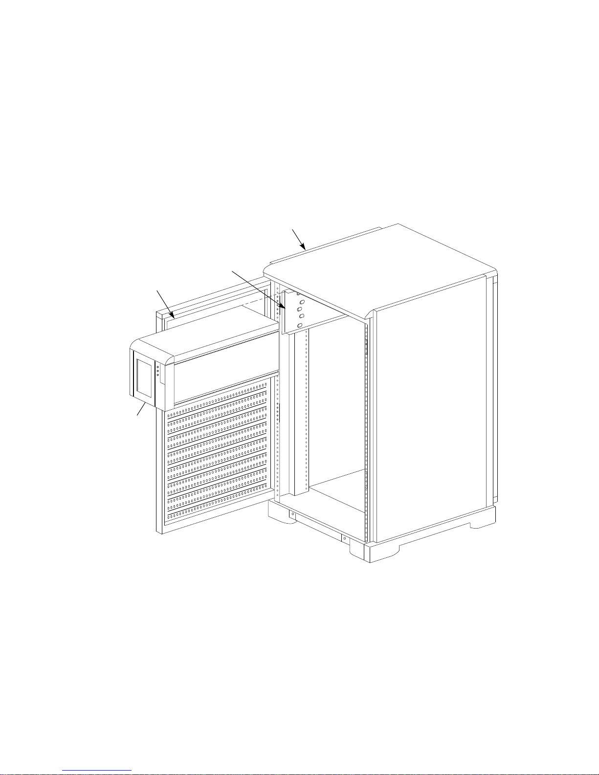
• TZLX-series tape drives—Up to two TZLX-series tape drives can be installed
in the upper area of the cabinet, as shown in Figure 1–3. A chassis rail is
used to support the tape drive from one side.
Figure 1–3 TZLX-Series Tape Drive
CHASSIS
TAPE
BEZEL
RAIL
CABINET
TZLx-SERIES
TAPE DRIVE
CXO-3954A-MC
1–6 Introduction
1.3 Power Configurations
The ac power distribution within the SH043-series cabinet can be configured in
one of the following three ways to provide the desired level of power redundancy
to the cabinet’s shelf-mounted peripheral devices:
• Single cabinet power configuration
• Dual shelf power configuration
• Dual cabinet power configuration
A description of each configuration option follows.
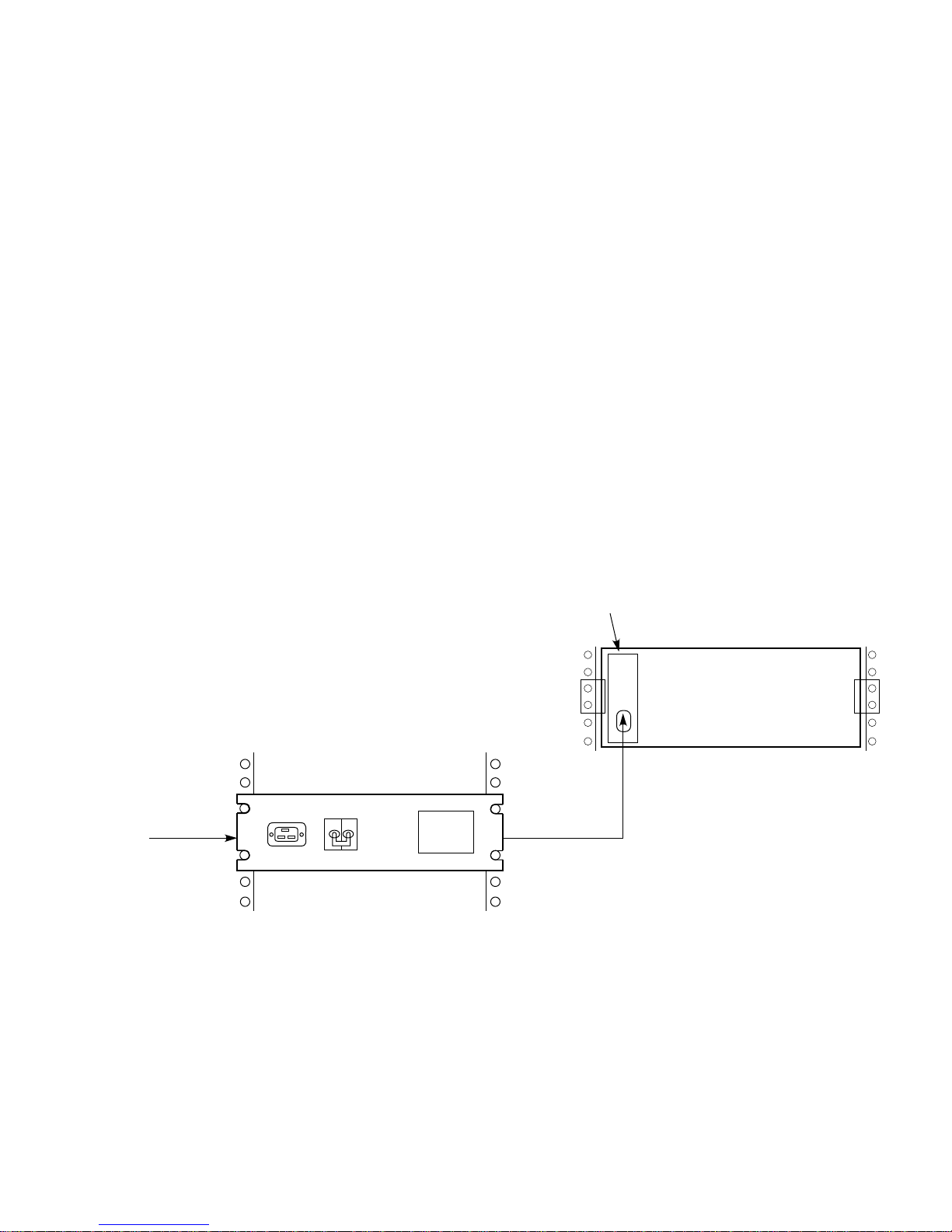
1.3.1 Single Cabinet Power Configuration
In the single cabinet power configuration, shown in Figure 1–4, a single ac power
source and CDU (A) are used to supply ac power to a single ac power supply
(A) in each shelf. This is the normal configuration for the cabinet, and it provides
no power redundancy to shelf peripheral devices.
Figure 1–4 Single Cabinet Power Configuration
AC POWER
SUPPLY A
PRIMARY
AC POWER
SOURCE
SBB SHELF
CDU A
PRIMARY
AC POWER
(BLACK
CABLE)
CXO-3937A-MC
Introduction 1–7
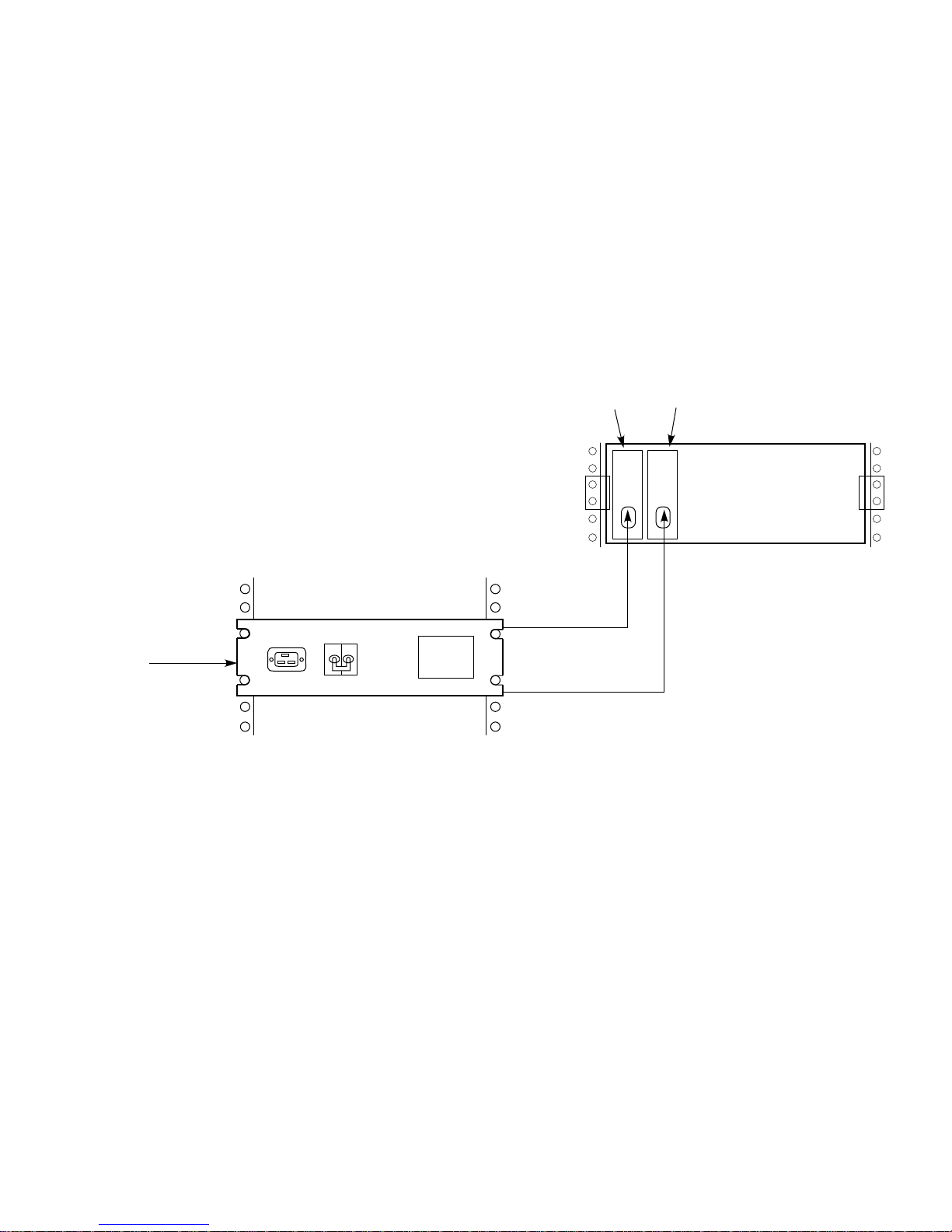
1.3.2 Dual Shelf Power Configuration
In the dual shelf power configuration, shown in Figure 1–5, a single primary
power source and CDU (A) are used to supply ac power to two ac power supplies
(A and B) in each shelf. If either power supply fails, the shelf remains powered
by the other supply. This configuration provides shelf power supply redundancy
to the shelf’s peripheral devices. The cabinet supports a maximum of six shelves
in the dual shelf power configuration.
Figure 1–5 Dual Shelf Power Configuration
PRIMARY
AC POWER
SOURCE
CDU A
AC POWER
SUPPLY A
PRIMARY
AC POWER
(BLACK OR
GRAY CABLE)
PRIMARY
AC POWER
(BLACK OR
GRAY CABLE)
AC POWER
SUPPLY B
SBB SHELF
CXO-3938A-MC
1–8 Introduction
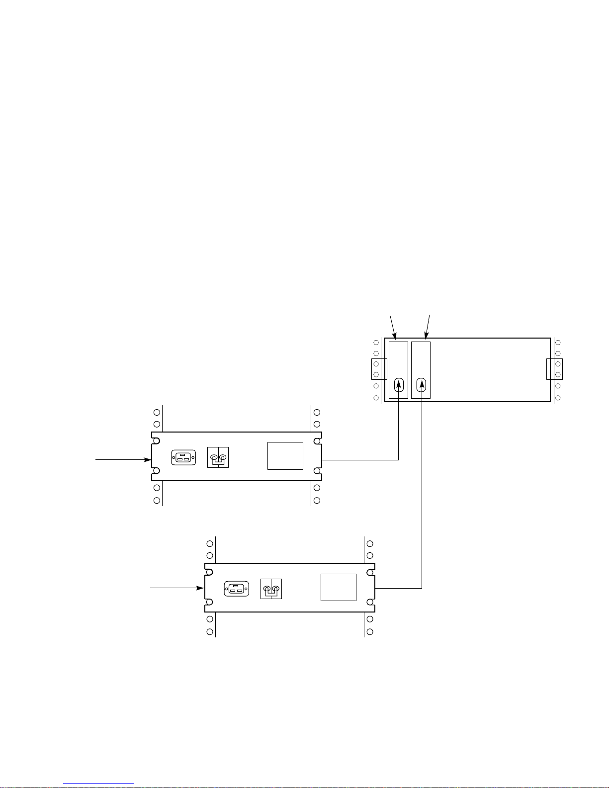
1.3.3 Dual Cabinet Power Configuration
In the dual cabinet power configuration, shown in Figure 1–6, an auxiliary power
source and a second CDU (B) are used to supply ac power to a second ac power
supply (B) in each shelf. If the primary power source, CDU A, or ac power supply
A fails, the shelf remains powered by ac power supply B. This configuration
provides complete power redundancy to the shelf’s peripheral devices.
Figure 1–6 Dual Cabinet Power Configuration
PRIMARY
AC POWER
SOURCE
AUXILLARY
AC POWER
SOURCE
CDU A
CDU B
AC POWER
SUPPLY A
PRIMARY
AC POWER
(BLACK
CABLE)
AC POWER
SUPPLY B
SBB SHELF
(GRAY
CABLE)
AUXILLARY
AC POWER
CXO-3936A-MC
Introduction 1–9

1.4 Cabinet Cooling System
Each StorageWorks shelf contains two rear-mounted blowers that move heat
from the shelf into the cabinet interior. The cabinet structure is such that heated
air moves from the cabinet interior up and out through the unused shelf positions
in the rear. It is then exhausted through the rear door. Logic signals allow the
status of the shelf blowers to be monitored by the host system.
Filler panels and air separation panels are used to properly route heated air
through the cabinet. Filler panels are flat plates that serve as covers for unused
shelf positions. Air separation panels are small baffles that mount just above
and outside the upper-most shelf in each side of the cabinet to prevent heated air
from being drawn down between the cabinet door and the shelf. Such air would
be drawn back into the shelf and would interfere with proper cooling.
1–10 Introduction

This chapter presents the information necessary to prepare a site for the
installation of the StorageWorks SH043-series cabinet.
2.1 General Considerations
SH043-series cabinets are intended for installation in Class A computer room
environments. Before installing the cabinet, make sure that the following
conditions have been met:
• The primary power source can supply the required amount of ac power, as
specified in Table 1–1.
• The site’s primary power receptacles are the correct versions for the power
plugs provided with the cabinet. The SH043-ZZ cabinet is supplied with a
power cable that has an IEC 309 plug.)
• The site floor can safely bear the weight of the cabinet, as specified in
Table 1–1. Keep in mind that the entire weight of the cabinet is borne by the
small surface area of the four leveler feet when the cabinet is installed in its
final position.
2
Site Preparation
• Adequate space is provided around the cabinet for opening the front and rear
doors, for accessing cables, and for adequate airflow. SH043-series cabinets
are not designed to be fastened to adjacent cabinets. See Figure 2–1 for
specific space requirements.
Site Preparation 2–1

Figure 2–1 Minimum Installation Clearances
31.50 in
600.0 mm
REAR
DOOR
SHO43-
SERIES
CABINET
FRONT
DOOR
29.33 in
60.0 cm
34.45 in
87.5 cm MAX
29.33 in
60.0 cm
CXO-3955A-MC
• The cabinet is positioned to allow external interface cables to reach to the
appropriate system units.
• If the cabinet is to be positioned next to other enclosures, there is sufficient
service loop in any connecting cables to allow the cabinet to be moved out for
access.
2.2 Equipment Grounding
SH043-series cabinets are normally connected to other equipment by one or
more interface buses. For both safety and reliable operation, proper grounding is
required between the cabinet and other equipment.
If enclosures are not connected to a common ground, there is a potential
for a personal injury as a result of electric shock.
When connecting a terminal to a controller within the cabinet, proper
grounding is required to prevent personnel injury and equipment damage.
For optimum safety and performance, it is recommended that the
terminal be powered by one of the two utility IEC outlets on the back of
each cable distribution unit (CDU). A spare power cord is furnished with
each cabinet for this purpose.
2–2 Site Preparation
WARNING
WARNING

If ground offset voltages generated in the power distribution system are excessive,
data transmission across interface buses can be affected. Significant performance
degradation or possible data corruption could result. SH043-series cabinets are
shipped with a ground strap (Digital part number 12–13756–A8) that is connected
to the rear of the unit. For optimum safety and performance, Digital recommends
that the ground strap be connected to the chassis of the host system.
Make sure that site power distribution systems meet local electrical codes prior to
the installation of SH043-series cabinets.
To make sure that the power distribution system will perform satisfactorily, a
power system survey should be done before installation. The following areas
should be investigated:
• Do all outlets have power ground connections?
• Do the power cables on all equipment at the site have grounding prongs?
• Are all power outlet neutral connections isolated from ground?
• Are the grounds for all outlets connected to the same power distribution
panel?
• Are all devices that are connected to the same breaker as the SH043
cabinet Underwriter’s Laboratories (UL) or International Electrotechnical
Commission (IEC) approved?
CAUTION
If there is a deficiency found in any area during the power survey, a
qualified electrician must correct it before installation may begin. Failure
to resolve power survey deficiencies before installing the equipment may
result in personnel injury as a result of electric shock.
If no problems are found during the survey, the site grounding system may be
considered to be adequate for personnel safety and reliable SH043-series cabinet
operation.
Site Preparation 2–3


This chapter describes the unpacking, installation, inspection, and powering of
StorageWorks SH043-series cabinets.
3.1 Unpacking the Cabinet
SH043-series cabinets are packed in a corrugated carton attached to a wooden
shipping pallet, as shown in Figure 3–1. Unpack the cabinet as follows:
Before unpacking the equipment, inspect the shipping carton for signs
of external damage. Report any damage to the local carrier and to
Multivendor Customer Services or your local Digital sales office.
Failure to thermally stabilize preconfigured storage subsystems may
damage drive media or associated electronics when the unit is turned on.
Environmental stabilization begins when the equipment is placed in the
room in which it is to be installed.
3
Unpacking and Installation
Note
CAUTION
1. Remove the cover, the fasteners, and the corrugated board from the pallet.
2. Remove the cartons containing the ramp set and skirt kit and set them aside.
3. Cut the shipping straps. Some cabinets are packaged in a plastic or barrier
bag. If the cabinet arrives in a plastic bag, leave the bag in place until
the cabinet has adjusted to the local temperature and humidity. Refer to
Appendix A for more information on environmental stabilization.
4. Once the cabinet is unpacked, examine the front and rear doors, right and left
side panels, top panel, and undercarriage for any apparent damage. Report
such problems immediately.
5. Retain the shipping container and all packing materials.
Unpacking and Installation 3–1
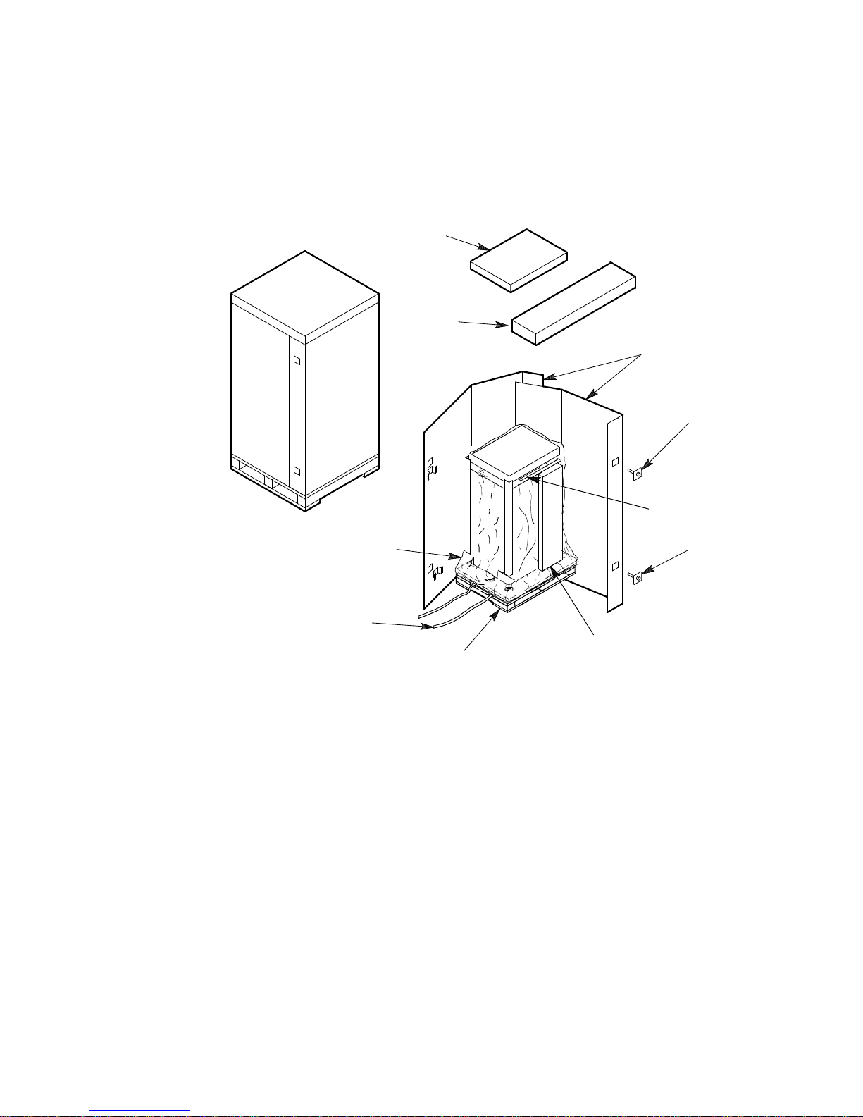
Figure 3–1 Shipping Container Contents
COVER
CARTON
CONTAINING
SKIRT KIT
CORRUGATED
BOARD
FASTENERS
MANUALS
PLASTIC OR
BARRIER BAG
SHIPPING
STRAPS
PALLET
FASTENERS
CARTON
CONTAINING
UNLOADING
RAMPS
CXO-3533A-TI
3–2 Unpacking and Installation

3.2 Removing the Cabinet from the Pallet
This section describes how to remove the cabinet from the pallet.
Use the following procedure to remove the cabinet from the shipping pallet:
1. Remove any packing material remaining on the pallet.
WARNING
Serious personal injury may result if correct safety precautions are not
taken during the unpacking procedure. All personnel should wear safety
glasses. The ramps, ramp side rails, and metal hardware should be
inspected for the following defects:
• Cracks more than 25 percent of the ramp depth, either across or
lengthwise on the ramp
• Knots or knotholes going through the thickness of the ramp and
greater than 50 percent of the ramp width
• Loose, missing, or broken ramp side rails
• Loose, missing, or bent metal hardware
If any of these defects exist, do not use the ramp. Investigate alternate
means of removing the cabinet or order a new ramp. (The part number
for the ramp set is 99–08897–05.)
2. Remove the two unloading ramps from the carton and inspect them.
3. Attach the ramps by fitting the metal prongs into the holes on the pallet, as
shown in Figure 3–2. Make sure that the arrows on the ramps match up with
the arrows on the pallet.
4. Extend the ramps to their full length.
5. See Figure 3–3 for the location of the shipping bolts. Remove the bolts.
6. Remove the shipping brackets, shown in Figure 3–3, from the cabinet levelers
and set them aside.
Unpacking and Installation 3–3

Figure 3–2 Shipping Pallet Ramp Installation
LEFT
UNLOADING
RAMP
SHIPPING
PALLET
RIGHT RAMP
ATTACHES HERE
EXTEND RAMP TO
FULL LENGTH
RIGHT
UNLOADING
RAMP
CXO-688D_S
3–4 Unpacking and Installation

Figure 3–3 Shipping Bolts and Brackets
LEVELER
SHIPPING
BOLT
SHIPPING
BRACKET
SHR_X1102A_89_SCN
WARNING
The levelers must be raised fully for the cabinet to roll easily down the
unloading ramps. Failure to do so may result in personnel injury as a
result of the cabinet tipping off the pallet or ramp.
7. Loosen the leveler locking nuts and screw the four cabinet levelers all the
way up into the cabinet.
WARNING
Three people are required to unload the cabinet from the shipping pallet.
Failure to use sufficient personnel may result in injury and equipment
damage.
8. Carefully roll the cabinet off the pallet and down the ramps to the floor as
shown in Figure 3–4.
Unpacking and Installation 3–5
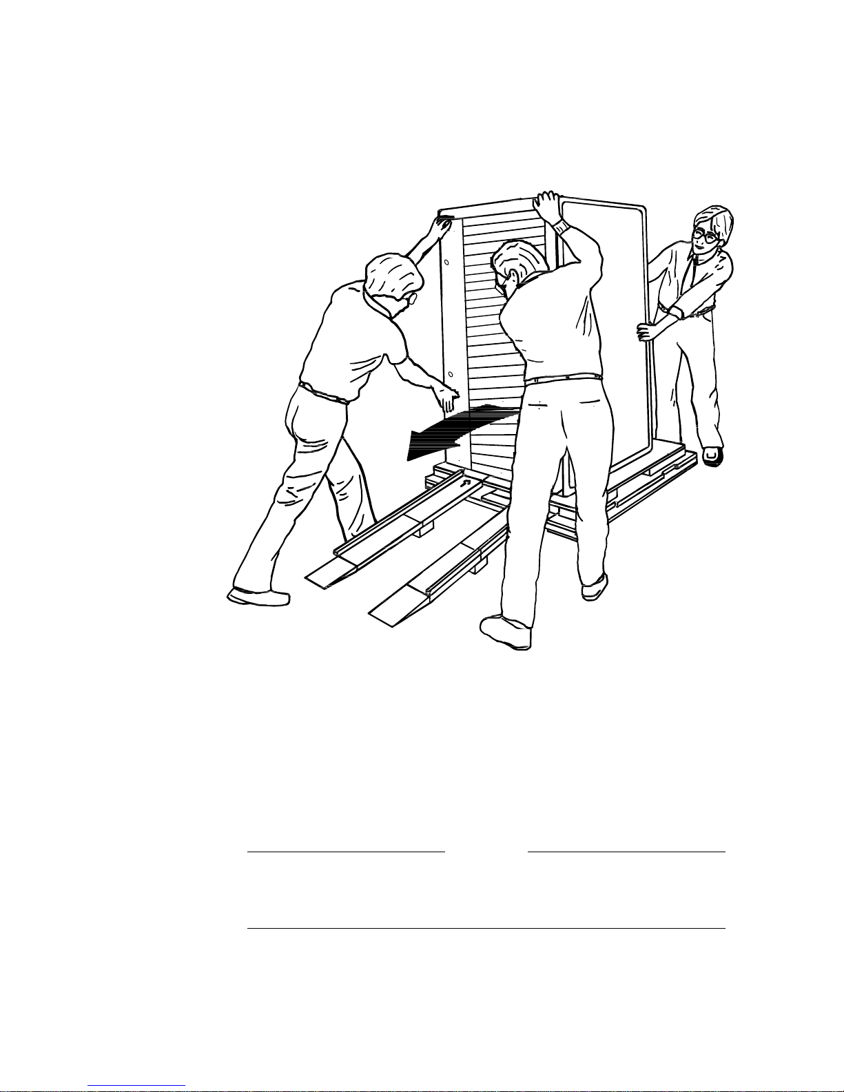
Figure 3–4 Removing the Cabinet from the Pallet
3.3 Configuring the Cabinet Rack Space
Any shelves to be added to the cabinet should be installed before it is placed in its
permanent position. See the chapter in this document pertaining to your specific
cabinet configuration for the proper location of shelves. See Chapter 6 for detailed
information and procedures regarding shelf bracket and shelf installation.
3.4 Placing the Cabinet
WARNING
Use extreme caution when rolling the cabinet across the floor. Failure to
raise all leveler feet and to provide a clear path for the cabinet’s casters
may result in the cabinet tipping over and injury to personnel.
Once the cabinet rack space is configured as desired, the cabinet may be rolled to
its final installation position. Secure loose cabinet cables up and out of the way
when rolling the cabinet.
3–6 Unpacking and Installation
CXO-3808A
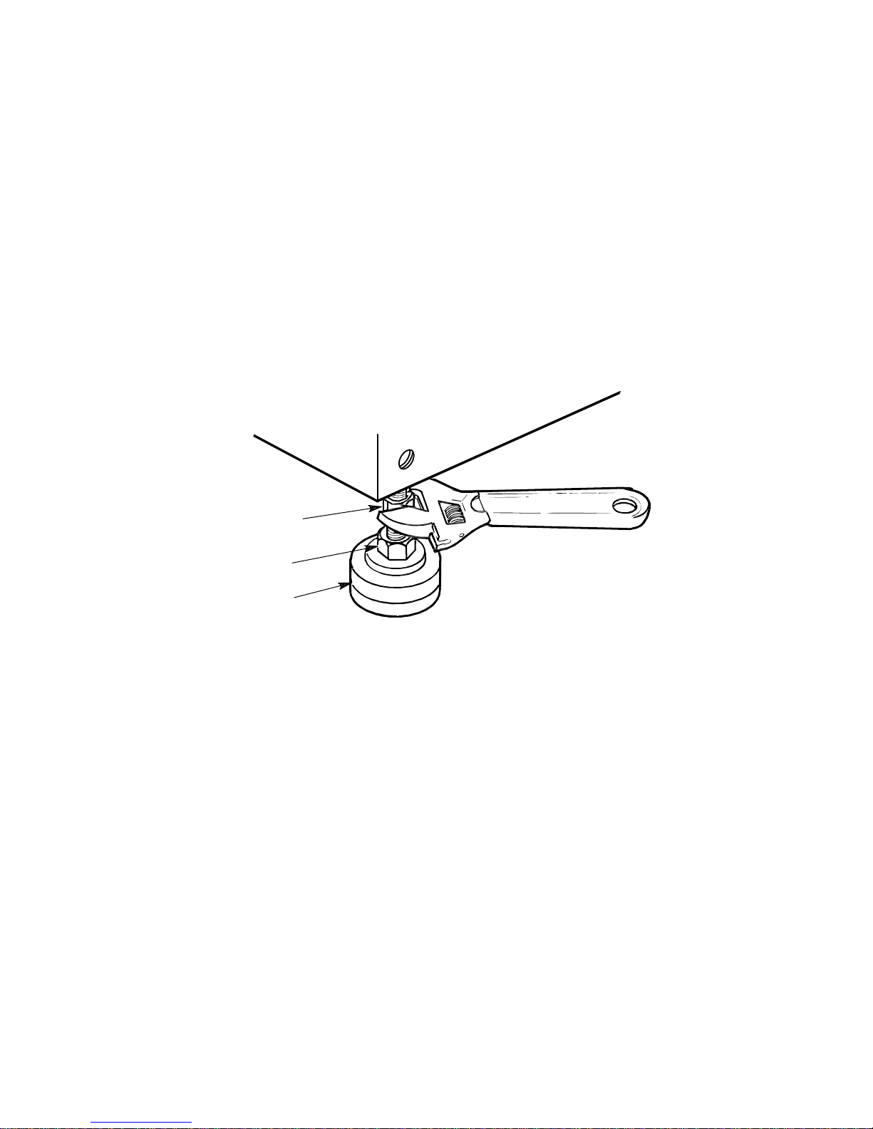
3.5 Leveling the Cabinet
Level the cabinet in its final position as follows:
1. Loosen the locknuts on all four leveler feet as shown in Figure 3–5.
2. Turn each leveler hex nut clockwise until the leveler foot contacts the floor.
3. Adjust all four leveler feet until the cabinet is level and the load is removed
from all casters. Verify that the casters spin freely.
4. Tighten the locknuts on all four leveler feet.
Figure 3–5 Leveler Foot Adjustment
LOCKNUT
LEVELER
HEX NUT
LEVELER
FOOT
3.6 Installing the Skirt Kit
The skirt kit is packaged separately inside the corrugated carton with the
cabinet. Installation of the skirt kit is optional. Install the skirt kit around the
base of the cabinet as follows:
1. Unpack the skirt kit carton and use Figure 3–6 to identify the right, left,
front, and rear skirts.
2. Position the skirts next to the cabinet, as shown in Figure 3–6.
3. The fasteners on the skirts consist of small pins with flat and barbed sides.
Using a Phillips screwdriver, turn the fasteners on each skirt until the flat
sides face up.
4. Position each skirt such that the fasteners mate with the receptacles on the
cabinet’s base.
5. Using a Phillips screwdriver, push each fastener straight into its mating
receptacle on the cabinet base.
(With the fasteners locked in place, a small amount of play allows the skirts
to be adjusted slightly up or down for proper alignment.)
CXO-3829A
Unpacking and Installation 3–7

Figure 3–6 Cabinet Skirt Installation
SIDE
SKIRT
REAR
SKIRT
3.7 Inspecting the Cabinet
Inspect the cabinet installation as follows:
1. Make sure that all hardware within the cabinet is fastened securely, and that
there are no loose pieces present in the cabinet interior.
2. Make sure that all four leveller feet are lowered to support the full weight of
the cabinet, and that the cabinet is level.
3. Make sure that there are no obstructions to the airflow from the shelf
blowers. (The side panels may need to be removed to check the shelf blowers.)
4. Check the identification label on the rear of the cabinet to verify that the
cabinet is configured to accept the power available at the site.
5. Make sure that all ac power cords connected from the shelves and cabinet
fans to the CDUs are firmly seated in their connectors at both ends.
6. Make sure that all signal cables internal to the cabinet are firmly seated in
their connectors at both ends.
SIDE
SKIRT
FRONT
SKIRT
CXO-3898A-MC
3–8 Unpacking and Installation

7. Make sure that all SBBs are seated firmly in their shelves.
8. Make sure that any necessary external interface cables are installed and
firmly seated in their connectors.
9. Make sure that the circuit breaker on each CDU is in the(OFF) position.
3.8 Powering the Cabinet
Once the cabinet has been inspected, power may be applied as follows:
1. Plug the primary power cables from each CDU into the appropriate site power
receptacles.
2. Switch the circuit breaker on each CDU to the(ON) position.
3. Verify that all shelf blowers are operating and that both status indicators
on each shelf power supply SBB are illuminated. Refer to the StorageWorks
Family User’s Guide for further information on shelf status indicators.
Failure to reduce the leakage current can result in equipment
performance degradation and personnel injury due to electric shock.
4. Measure the cabinet’s leakage current. If the leakage current exceeds 3.5 mA
after installation, Digital recommends that power cables with industrial type
B, IEC 950 connectors be installed.
WARNING
5. Initialize the storage subsystem. Procedures for initializing the cabinet’s
controller and storage devices are specific to the host system to which it is
connected. Refer to the appropriate system documentation for initialization
procedures.
Unpacking and Installation 3–9


4
Configuring SH043 Storage-Only Cabinets
This chapter describes the configuration of the SH043 storage-only cabinet. This
storage subsystem uses only the StorageWorks SHDZZ–ZZ shelf type. The Small
Computer Systems Interface 2 (SCSI–2) interface is used as the communications
path between the cabinet’s storage devices and their external controllers. SH043
storage-only cabinets can be configured with up to 10 storage shelves.
WARNING
While working in the cabinet interior, ac power must be removed from
cabinet components. Failure to do so may result in personnel injury as a
result of electric shock.
Prior to performing any of the procedures in this chapter, remove ac power from
the cabinet components. If the cabinet is installed and operating, spin down all
disk drives and halt all tape drives in the cabinet. Switch the circuit breaker on
the front panel of the cabinet’s cable distribution units (CDUs) to the(OFF)
position.
4.1 Cabinet Configuration
Failure to install cabinet components in the proper order could result in
cabinet instability, injury to personnel, and damage to equipment.
To maintain FCC compliance and proper airflow, filler panels and air
separation panels must be installed as specified for your particular
cabinet configuration. See Section 4.2 for further information.
The order of shelf installation in SH043 storage-only cabinets is predetermined to
allow for cabinet loading and cable length factors. Figures 4–1 and 4–2 show the
layout of both the front and rear of the storage-only cabinet. To prevent cabinet
instability, shelves must be installed in the order shown by the position numbers
in the illustrations.
WARNING
Note
Configuring SH043 Storage-Only Cabinets 4–1
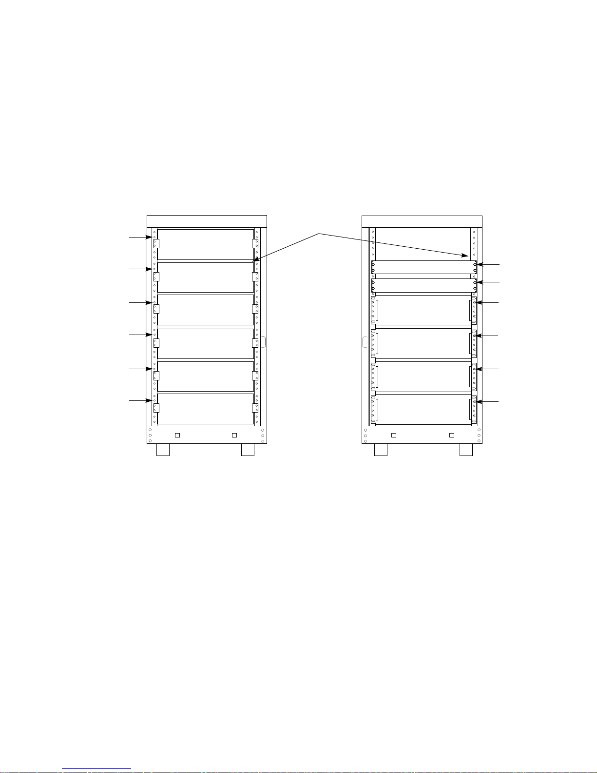
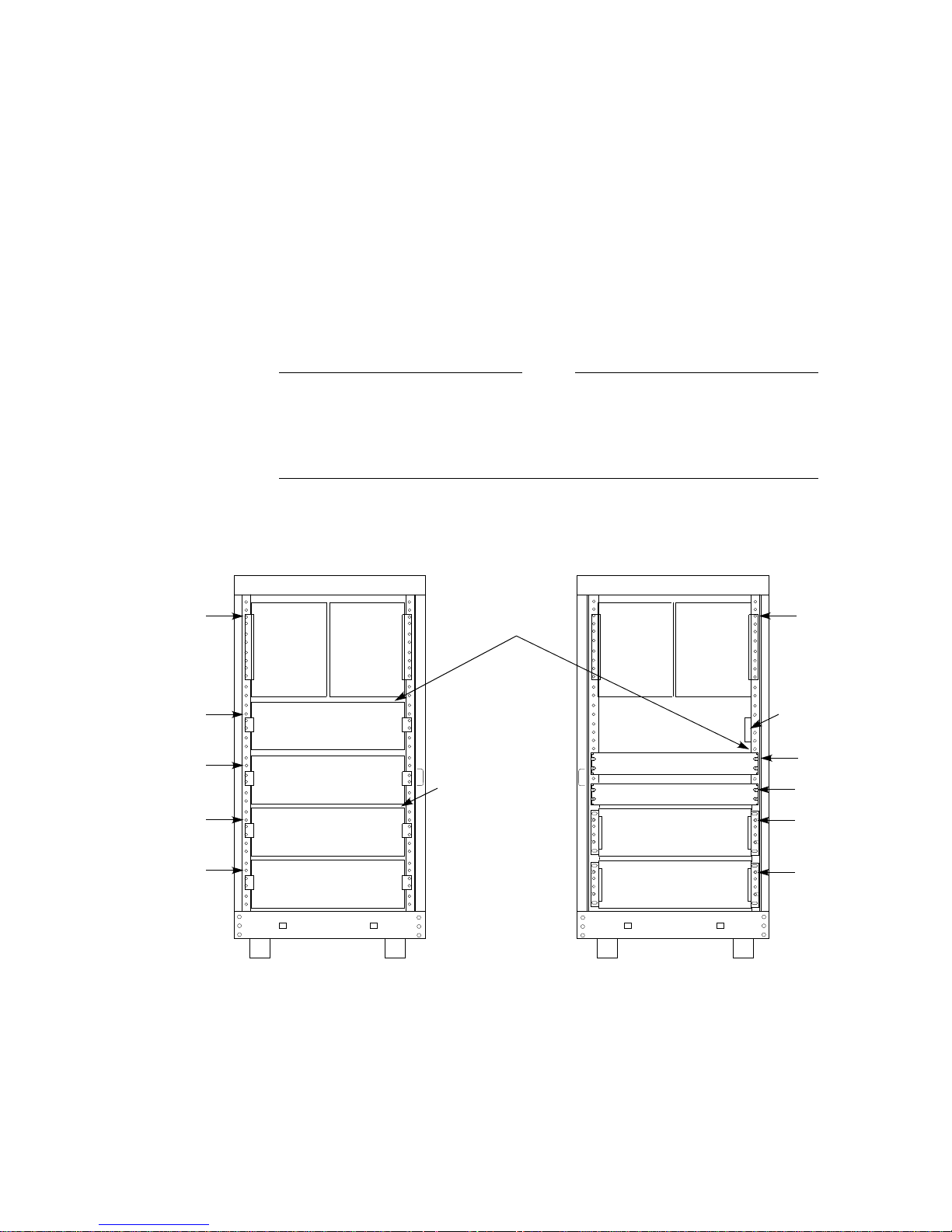
4.1.1 Shelf Locations
Figure 4–1 shows the proper cabinet rail mounting holes for each shelf location
when TZLX-series tape drives are not installed. Shelf mounting hole numbers
are counted from the top of each rail. The hole number assignments shown in
the figure identify the mounting holes for each shelf’s top bracket screw. See
Chapter 6 for detailed procedures pertaining to the mounting of StorageWorks
shelves.
Figure 4–1 SH043 Storage-only Cabinet Shelf Locations
MOUNTING
LOCATIONS
HOLE
#2
HOLE
#8
HOLE
#14
HOLE
#20
HOLE
#26
HOLE
#32
STORAGE
POSITION S10
STORAGE
POSITION S5
STORAGE
POSITION S4
STORAGE
POSITION S1
STORAGE
POSITION S2
STORAGE
POSITION S3
CABINET FRONT
FRONT-TO-REAR
SCSI-2 CABLE
ROUTING POINTS
CDU B
CDU A
STORAGE
POSITION S9
STORAGE
POSITION S8
STORAGE
POSITION S7
STORAGE
POSITION S6
CABINET REAR
MOUNTING
LOCATIONS
HOLE
#7
HOLE
#10
HOLE
#14
HOLE
#20
HOLE
#26
HOLE
#32
CXO-3900A-MC
4.1.2 TZLX-Series Tape Drive/Shelf Locations
Figure 4–2 shows the proper cabinet rail mounting holes for each shelf location
when TZLX-series tape drives are installed. Mounting hole numbers are counted
from the top of each rail. The hole number assignments shown in the figure
identify the mounting holes for each shelf’s top bracket screw and for the round
standoff chassis rail locating hole for TZLX-series tape drives. See Chapter 6
for detailed procedures pertaining to the mounting of StorageWorks shelves. See
Chapter 7 for detailed procedures pertaining to the mounting of the tape drive.
Note that the TZLX-series tape drive extends from the front to the rear of the
SH043 cabinet and utilize the upper two shelf mounting positions on each side.
4–2 Configuring SH043 Storage-Only Cabinets

Figure 4–2 SH043 Storage-only Cabinet Shelf and Tape Drive Locations
MOUNTING
LOCATIONS
HOLE
#3
HOLE
#14
HOLE
#20
HOLE
#26
HOLE
#32
TZLx-SERIES
TAPE DRIVE
POSITION T2
STORAGE
POSITION S4
STORAGE
POSITION S1
STORAGE
POSITION S2
STORAGE
POSITION S3
CABINET FRONT
TZLx-SERIES
TAPE DRIVE
POSITION T1
FRONT-TO-REAR
SCSI-2 CABLE
ROUTING POINTS
TZLx-SERIES
TAPE DRIVE
POSITION T1
CDU B
CDU A
STORAGE
POSITION S6
STORAGE
POSITION S5
CABINET REAR
TZLx-SERIES
TAPE DRIVE
POSITION T2
MOUNTING
LOCATIONS
HOLE
#3
HOLE
#19
HOLE
#22
HOLE
#26
HOLE
#32
CXO-3956A-MC
4.2 Filler and Air Separation Panels
To maintain FCC compliance and proper airflow, filler panels and air
separation panels must be installed as specified for your particular
cabinet configuration and in accordance with the following guidelines.
Filler panels can be installed in empty shelf positions to control air flow and
electromagnetic emissions and for the purpose of cosmetics. Filler panels are
normally supplied and installed based on the specific configuration of the SH043
storage-only cabinet ordered. At least two filler panels are shipped with each
cabinet. Install filler panels using the following guidelines:
• If a particular filler panel configuration is specified for your cabinet, install
the panels exactly as specified.
• If a particular filler panel configuration is not specified for your cabinet, use
filler panels in all open slots below the highest shelf installed. Repeat for
each side of the cabinet.
• To ensure proper cooling air flow, never install filler panels above the highest
shelf installed in the cabinet.
See Chapter 6 for details on the installation of filler panels.
Note
Configuring SH043 Storage-Only Cabinets 4–3

Two air separation panels are supplied with each cabinet. Install an air
separation panel just above the upper-most shelf in each side of the cabinet. Air
separation panels are not required above TZLX-series tape drives. See Chapter 6
for details on the installation of air separation panels.
4.3 Power Configuration
The power in SH043 storage-only cabinets can be configured in any of the forms
described in Section 1.3. See Chapter 8 for detailed procedures on configuring
power within the cabinet.
4.4 Signal Cabling and Routing
Signal cabling in the SH043 storage-only cabinet consists of inter-shelf SCSI–2
cabling and shelf-host SCSI–2 controller cabling.
4.4.1 Shelf SCSI–2 Cable Selection and Connection
Refer to the StorageWorks Family Configuration Guide and the StorageWorks
Family User’s Guide for details on how to select and connect SCSI–2 cables to the
cabinet’s shelves.
4.4.2 SCSI–2 Cable Routing
SCSI–2 signal cables enter SH043 storage-only cabinets through openings in the
rear edges of the base pan of the cabinet. Cables destined for rear shelves are
normally routed along the base pan to the right-most vertical rail. They are then
routed to the the right-hand side of each rear shelf along the rail.
SCSI–2 cables destined for front shelves are routed along the base pan and up the
right-hand vertical cabinet rail to a point just above the CDUs (refer to Figures
4–1 and 4–2). They then pass into the interior of the cabinet and across to an
opening in the vertical chassis rail behind the two right-hand shelf brackets of
positions S5 and S10. They pass through the opening and out to the front of the
cabinet through the space between the S5/S10 shelf brackets. On the front of
the cabinet, cables are normally routed along the right vertical cabinet rail to
the right-hand side of each shelf along the rail. Half-meter, SCSI–2 cables are
normally used to link adjacent shelves to each other.
When TZLX-series tape drives are installed, there is a space between the bottom
of the drives and shelf position S4 (refer to Figure 4–2). This space is normally
used for the routing of SCSI–2 cables from the rear to the front of the cabinet.
4.4.3 General Cable Routing Rules
Cables should be routed and installed with the following rules in mind:
Cabinet rail edges may be sharp and can slice or abrade skin or cable
insulation.
• Cables should be routed in a manner that allows the shortest overall cable
length.
WARNING
• Signal cables should be kept away from power cables.
• Care should be taken to avoid sharp cable bends.
4–4 Configuring SH043 Storage-Only Cabinets

• Cables should be routed to allow StorageWorks building blocks (SBBs) and
controller modules to be freely inserted and removed from their shelves.
• Cables should not be routed tightly against the metal edges of the cabinet.
• Signal cable bundling along the outside of the cabinet rails should be done to
allow the doors to easily close.
• Cables should be fastened along cabinet rails using cable ties or nylon cable
clamps, U-nuts, and screws. Added cables should be included in existing
cable clamps where possible.
Configuring SH043 Storage-Only Cabinets 4–5


5
Configuring SH043 Controller/Storage Cabinets
This chapter describes the configuration of SH043 controller/storage cabinets.
These storage subsystems use StorageWorks HS-family array controllers
mounted in SHxzz–zz shelves. Storage devices are housed in SHDZZ–ZZ shelves.
StorageWorks HS-family array controllers use the Small Computer System
Interface 2 (SCSI–2) interface as the communication path with the host computer.
The SCSI–2 interface is used as the storage device bus in all subsystems. SH043
controller/storage cabinets can be configured with up to four controllers in
redundant pairs and with up to nine storage shelves.
Refer to the StorageWorks BA350–EA Modular Storage Shelf User’s Guide for
further information on HS-family array controllers and their installation.
WARNING
While working in the cabinet interior, ac power must be removed from
cabinet components. Failure to do so may result in personnel injury as a
result of electric shock.
Prior to performing any of the procedures in this chapter, remove ac power from
the cabinet components. If the cabinet is installed and operating, spin down all
disk drives and halt all tape drives in the cabinet. Switch the circuit breaker on
the front panel of the cabinet’s cable distribution units (CDUs) to the(OFF)
position.
5.1 Cabinet Configuration
Failure to install cabinet components in the proper order could result in
cabinet instability, injury to personnel, and damage to equipment.
To maintain FCC compliance and proper airflow, filler panels and air
separation panels must be installed as specified for your particular
cabinet configuration. See Section 5.2 for further information.
WARNING
Note
Configuring SH043 Controller/Storage Cabinets 5–1

The order of shelf installation in SH043 controller/storage cabinets is
predetermined to allow for cabinet loading and cable length factors. Figures
5–1 and 5–2 show the layout of both the front and rear of the controller/storage
cabinet. To prevent cabinet instability, shelves must be installed in the order
shown by the position numbers in the illustrations.
5.1.1 Shelf Locations
Figure 5–1 shows the proper cabinet rail mounting holes for each shelf location
when TZLX-series tape drives are not installed. Note that storage position
S7 may instead be used for the installation of a second controller shelf. Shelf
mounting hole numbers are counted from the top of each rail. The hole number
assignments shown in the figure identify the mounting holes for each shelf’s top
bracket screw. See Chapter 6 for detailed procedures pertaining to the mounting
of StorageWorks shelves.
Note
The SHxzz–zz controller/storage shelf consists of a controller shelf with an
attached storage shelf. In systems using SHxzz–zz shelves but not using
tape drives, storage positions S1 and S6 are physically attached to and
are dedicated to their respective controllers.
Figure 5–1 SH043 Controller/Storage Cabinet Shelf Locations
MOUNTING
LOCATIONS
HOLE
#2
HOLE
#8
HOLE
#14
HOLE
#20
HOLE
#26
HOLE
#32
STORAGE
POSITION S9
STORAGE
POSITION S4
STORAGE
POSITION S3
CONTROLLER
POSITION C1
STORAGE
POSITION S1
STORAGE
POSITION S2
CABINET FRONT
FRONT-TO-REAR
SCSI-2 CABLE
ROUTING POINTS
INTERNAL
CI CABLE
ROUTING
POINT
CDU B
CDU A
STORAGE
POSITION S8
STORAGE
POSITION S7
CONTROLLER
POSITION C2
STORAGE
POSITION S6
STORAGE
POSITION S5
CABINET REAR
MOUNTING
LOCATIONS
CI BULKHEAD
HOLE
#7
HOLE
#10
HOLE
#14
HOLE
#20
HOLE
#26
HOLE
#32
5–2 Configuring SH043 Controller/Storage Cabinets
CXO-3902A-MC
5.1.2 TZLX-Series Tape Drive/Shelf Locations
Figure 5–2 shows the proper cabinet rail mounting holes for each shelf location
when TZLX-series tape drives are installed. Mounting hole numbers are counted
from the top of each rail. The hole number assignments shown in the figure
identify the mounting holes for each shelf’s top bracket screw and for the round
standoff slide locating hole for the TZLX-series tape drives. Refer to Chapter 6 for
detailed procedures pertaining to the mounting of StorageWorks shelves. Refer to
Chapter 7 for detailed procedures pertaining to the mounting of TZLX-series tape
drives. Note that the TZLX-series tape drive extends from the front to the rear
of the SH043 cabinet and utilizes the upper two shelf mounting positions on each
side.
Note
The SHxzz–zz controller/storage shelf consists of a controller shelf with
an attached storage shelf. In systems using SHxzz–zz shelves and TZLXseries tape drives, storage positions S1 and S4 are physically attached to
and are dedicated to their respective controllers.
Figure 5–2 SH043 Controller/Storage Cabinet Shelf and Tape Drive Locations
MOUNTING
LOCATIONS
HOLE
#3
HOLE
#14
HOLE
#20
HOLE
#26
HOLE
#32
TZLx-SERIES
TAPE DRIVE
POSITION T2
STORAGE
POSITION S3
CONTROLLER
POSITION C1
STORAGE
POSITION S1
STORAGE
POSITION S2
CABINET FRONT
TZLx-SERIES
TAPE DRIVE
POSITION T1
FRONT-TO-REAR
SCSI-2 CABLE
ROUTING POINTS
INTERNAL
CI CABLE
ROUTING
POINT
TZLx-SERIES
TAPE DRIVE
POSITION T1
CDU B
CDU A
CONTROLLER
POSITION C2
STORAGE
POSITION S5
STORAGE
POSITION S4
CABINET REAR
TZLx-SERIES
TAPE DRIVE
POSITION T2
MOUNTING
LOCATIONS
HOLE
#3
CI BULKHEAD
HOLE
#19
HOLE
#22
HOLE
#26
HOLE
#32
CXO-3957A-MC
Configuring SH043 Controller/Storage Cabinets 5–3

5.2 Filler and Air Separation Panels
To maintain FCC compliance and proper airflow, filler panels and air
separation panels must be installed as specified for your particular
cabinet configuration and in accordance with the following guidelines.
Filler panels can be installed in empty shelf positions to control air flow and
electromagnetic emissions and for the purpose of cosmetics. Filler panels are
normally supplied and installed based on the specific configuration of the SH043
controller/storage cabinet ordered. At least two filler panels are shipped with
each cabinet. Install filler panels using the following guidelines:
• If a particular filler panel configuration is specified for your cabinet, install
the panels exactly as specified.
• If a particular filler panel configuration is not specified for your cabinet, use
filler panels in all open slots below the highest shelf installed. Repeat for
each side of the cabinet.
• To ensure proper cooling air flow, never install filler panels above the highest
shelf installed in the cabinet.
Refer to Chapter 6 for details on the installation of filler panels.
Two air separation panels are supplied with each cabinet. Install an air
separation panel just above the upper-most shelf in each side of the cabinet.
Air separation panels are not required above TZLX-series tape drives. Refer to
Chapter 6 for details on the installation of air separation panels.
Note
5.3 Power Configuration
The power in SH043 controller/storage cabinets can be configured in any of the
forms described in Section 1.3. Refer to Chapter 8 for detailed procedures on
configuring power within SH043 controller/storage cabinets.
5.4 Host SCSI–2 Signal Cabling and Routing
The SCSI–2 interface cables used to communicate with the host are routed
directly from the controller to the host. A intermediate bulkhead is not used.
5.4.1 Host SCSI–2 Signal Cable Routing
Route the host SCSI–2 interface cables as follows:
1. Route host SCSI–2 cables into SH043 controller/storage cabinets through the
openings in the rear edges of the base pan of the cabinet.
2. Route host SCSI–2 cables destined for rear controllers directly up the rear
right-hand vertical rail to the rear controller shelf.
3. Route host SCSI–2 cables destined for rear controllers along the base pan
to the rear right-hand vertical rail and upward to the pass-through location
shown in either Figure 5–1 or 5–2.
5–4 Configuring SH043 Controller/Storage Cabinets

4. Route the cables from the pass-through location to their respective controllers
as follows:
• Route the cable across the interior of the cabinet to an opening in the
vertical cabinet rail behind the two right-hand shelf brackets of positions
C1 and S3 (refer to Figures 5–1 and 5–2).
• Pass the cable through the opening and out to the front of the cabinet
through the space between the C1/S3 shelf brackets to the front controller
in position C1.
5.5 Shelf Signal Cabling and Routing
5.5.1 Shelf SCSI–2 Cable Selection and Connection
Refer to the StorageWorks Family Configuration Guide and the StorageWorks
BA350-EA Modular Storage Shelf User’s Guide for details on the selection of
SCSI–2 cables and their connection to the cabinet’s shelves.
5.5.2 SCSI–2 Cable Routing
SCSI–2 cables from the front controller to the controller’s associated front storage
shelves are normally routed along the right-hand vertical cabinet rail to the
right-hand side of each shelf. Half-meter, SCSI–2 cables are normally used to
link adjacent shelves or tape drives to each other.
SCSI–2 cables connecting front shelves to rear shelves pass to the rear of the
cabinet via the opening between the right-hand shelf brackets at positions S4 and
S9 (refer to Figure 5–1). They pass through this opening and into the interior
of the cabinet through the opening in the vertical cabinet rail behind the S4/S9
brackets. They then pass across the interior of the cabinet to the unused shelf
position above the CDUs. They pass through the right-hand side of the unused
shelf position and along the right-hand cabinet rail to the appropriate rear
shelves.
When TZLX-series tape drives are installed, there is a space between the bottom
of the drives and shelf position S3 (refer to Figure 5–2). This space is normally
used for the routing of SCSI–2 cables from the rear to the front of the cabinet.
Table 5–1 specifies the SCSI–2 cable length required to connect each controller
position with its companion shelves in SH043 controller/storage cabinets.
Table 5–1 SH043 Controller/Storage Cabinet SCSI–2 Cable Lengths
Controller Position Storage Shelf Position
C1 S1, S2, S3, S4, S9 1.00 m (3.28 ft)
C1 S5, S6, S7, S8 2.00 m (6.56 ft)
C1 T1, T2 2.00 m (6.56 ft)
C2 S5, S6, S8 1.00 m (3.28 ft)
Cable Length
Required
Configuring SH043 Controller/Storage Cabinets 5–5

Following are some standard SCSI–2 bus configurations:
Shelf connections for single-controller systems with no tape drives are as follow
(refer to Figure 5–1):
• Single storage shelf
C1–S1 C1–S2 C1–S3 C1–S4 C1–S5 C1–S6
• Serially cabled multiple storage shelves
C1–S1–S2 C1–S3–S4 C1–S5 C1–S6 C1–S7
Shelf connections for single-controller systems with tape drives are as follow
(refer to Figure 5–2):
C1–S1 C1–S2 C1–S3 C1–S4 C1–S5 C1–T1–T2
Shelf connections for dual-controller systems with single storage shelves are as
follows (refer to Figure 5–1):
C1–S1 C1–S2 C1–S3 C1–S4 C1–S9 C2–S6 C2–S8
5.6 General Signal Cable Routing Rules
Cables should be routed and installed with the following rules in mind:
WARNING
Cabinet rail edges may be sharp and can slice or abrade skin or cable
insulation.
• Cables should be routed in a manner that allows the shortest overall cable
length.
• Signal cables should be kept away from power cables.
• Care should be taken to avoid sharp cable bends.
• Cables should be routed to allow SBBs and controller modules to be freely
inserted and removed from their shelves.
• Cables should not be routed tightly against the metal edges of the cabinet.
• Signal cable bundling along the outside of the cabinet rails should be done to
allow the doors to easily close.
• Cables should be fastened along cabinet rails using cable ties or nylon cable
clamps, U-nuts, and screws. Added cables should be included in existing
cable clamps where possible.
5–6 Configuring SH043 Controller/Storage Cabinets

Installing StorageWorks Shelves
This chapter describes the details of the installation of StorageWorks shelves
into SH043-series cabinets. Procedures for front and rear shelf installation are
presented. The installation of filler panels and air separation panels in both the
front and rear of the cabinet are also covered.
6.1 General Shelf Mounting Considerations
Note
In the following descriptions and procedures, the terms front and rear
are references to locations in the cabinet. The terms inner and outer are
references to positions on the shelf brackets.
Each StorageWorks shelf is mounted in the cabinet with a bracket set (BA35x–
RB) (Refer to Figure 1–2.) Each bracket set consists of a pair of shelf brackets,
stop brackets, and locking brackets. (A typical bracket set is shown in
Figure 6–2.) The stops are attached to the inner portion of the shelf brackets to
position the shelf within the bracket. The locking brackets fix the shelf in place.
Various combinations of stop positions and locking bracket size are necessary to
situate a particular shelf for proper clearance from the cabinet doors.
6
The same shelf bracket and stop bracket parts are used to mount all types of
StorageWorks shelves in all locations. The bracket set for shelves mounted in
various positions in the cabinet differs only in that the locking brackets are
unique parts sized for specific cabinet positions.
Filler panels are installed in some unused shelf positions in the cabinet. Filler
panels are normally installed after shelf installation
An air separation panel is required in both the front and rear of the cabinet to
prevent the recirculation of heated air to the cabinet’s shelves. The air separation
panels are mounted just above the upper-most shelf in each side of the cabinet.
Air separation panels are normally installed after shelf installation.
WARNING
While working in the cabinet interior, ac power must be removed from
cabinet components. Failure to do so may result in personnel injury as a
result of electric shock.
Prior to performing any of the procedures in this chapter, remove ac power from
the cabinet components. If the cabinet is installed and operating, spin down all
disk drives and halt all tape drives in the cabinet. Switch the circuit breaker on
the front panel of the cabinet’s CDUs to the(OFF) position.
Installing StorageWorks Shelves 6–1
6.2 Accessing the Cabinet Rack Space
In maximum configurations where access to the interior of the cabinet is limited,
external cabinet panels may need to be removed before shelves can be installed
or reconfigured. Section 6.2.1 presents procedures for removing exterior cabinet
panels.
The front and rear cabinet doors are held closed by locks mounted near the top
and bottom of each door. The locks are released by turning them counterclockwise
with a 5/32-inch hex wrench.
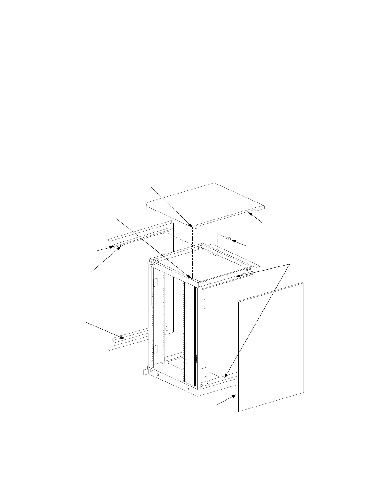
6.2.1 Removing the Exterior Cabinet Panels
As shown in Figure 6–1, there are two side panel hanger clips on each side of the
cabinet. A matching set of hanger clips are attached to each side panel. Remove
the side panels as follows:
Figure 6–1 Exterior Cabinet Panel Removal and Installation
FASTENER
PIN
(4 PLACES)
NYLON SNAP
FASTENER
(4 PLACES)
TOP COVER
UPPER
SIDE PANEL
HANGER
CLIP
LOWER
SIDE PANEL
HANGER
CLIP
LIP
M6x40mm BOLT
(4 PLACES)
SIDE PANEL
HANGER
CLIPS
CABINET
FRONT
SIDE PANEL
NOTE: FRONT AND REAR DOORS NOT SHOWN FOR CLARITY
6–2 Installing StorageWorks Shelves
CXO-3899A-MC

1. Move the cabinet away from adjacent enclosures as necessary.
2. Loosen the top cover by pushing up on its front and rear edges until it snaps
free of its fasteners.
The top cover is heavy and awkward to lift. Removing it is a twoperson task. Failure to use sufficient personnel may result in injury or
equipment damage.
3. Using two persons, lift the top cover from the cabinet and set it aside.
4. Remove the bolts attaching the side panels to the top side rails of the cabinet.
5. Grasp a panel along its front and rear edges and lift up until the hanger clips
disengage. Lift the panel away from the cabinet.
6. Repeat the previous step to remove the other panel.
6.3 Installing the Shelves
Shelf bracket installations for front and rear shelves are shown in Figures 6–2
and 6–3. Using the illustrations as a guide, install shelf brackets as follows:
WARNING
WARNING
Cabinet rail edges may be sharp and can slice or abrade skin or cable
insulation.
Note
Two small ESD grounding posts are provided with the cabinet. One is
located on a front vertical cabinet rail, and one on a rear rail. Should an
ESD grounding post interfere with the installation of a shelf, move the
post out of the way to any free hole on the cabinet.
1. Turn the cabinet power off as described in Section 6.1.
2. Determine the correct shelf mounting locations and corresponding cabinet rail
mounting holes for the shelf bracket. Refer to the chapter in this document
pertaining to your specific cabinet configuration for this information.
3. Position the shelf bracket at the correct mounting holes just behind the outer
flange of the vertical cabinet rail, as shown.
4. Using the shelf bracket as a template, mark the two U-nut mounting holes on
the inner flange of the cabinet rail.
5. Remove the shelf bracket and install two U-nuts along the inner flange of the
cabinet rail at the holes marked in step 4.
6. Position and fasten the shelf bracket to the outer flange of the cabinet rail
with two screws, as shown.
7. Fasten the bracket to the U-nuts with two screws.
Installing StorageWorks Shelves 6–3

8. Using Table 6–1, determine the correct stop bracket position for the shelf type
being installed.
Table 6–1 Shelf Stop Bracket Positions
StorageWorks Shelf Type
SHDZZ–ZZ 4 1
Front Shelf Stop Bracket
Position
Rear Shelf Stop Bracket
Position
9. Insert the tab on the stop bracket into the slot at the correct stop position on
the shelf bracket. Fasten the stop bracket to the shelf bracket, as shown.
10. Repeat steps 2 through 9 to mount the companion shelf bracket on the
opposite cabinet rail. To ensure proper alignment of the brackets, use care to
mount the bracket to the correct rail mounting holes.
11. With the power supply end of the shelf to the left and the blowers facing
the cabinet, slide the shelf into the shelf brackets until it contacts the inner
stop brackets. The shelf should slide smoothly into the brackets. If it binds,
remove it and check the alignment of the shelf brackets. The shelf bracket
mounting screws may need to be loosened slightly to allow the brackets
to align with the shelf. Retighten the screws when the shelf brackets are
properly aligned.
12. Using Table 6–2, verify that you have the correct locking bracket part number
for the shelf type and position (front or rear) being installed.
Table 6–2 Shelf Locking Bracket Part Numbers
StorageWorks Shelf Type
SHDZZ–ZZ 74–46441–01 74–46439–01
Front Shelf Locking Bracket
Part No.
Rear Shelf Locking
Bracket Part No.
13. Once the shelf is positioned within the shelf brackets, install the shelf’s
locking brackets to both shelf brackets with screws, as shown. Push the
locking bracket against the shelf to seat it before tightening the screws.
6–4 Installing StorageWorks Shelves

Figure 6–2 Horizontal Shelf Bracket Installation
U-NUT, 10-32
(2 PLACES)
FRONT
VERTICAL
CABINET
RAIL
FRONT SHELF
LOCKING
BRACKET
STOP
POSITION
#2
STOP
POSITION
#1
STOP
POSITION
#4
STOP
POSITION
#3
STOP
POSITION
#5
STOP
BRACKET
SHELF MOUNTING
BRACKET (LEFT
FRONT POSITION)
SCREW, THRL 10-32
TRS .500 XRCS
(7 PLACES)
CXO-3768A-MC
Installing StorageWorks Shelves 6–5

Figure 6–3 Rear Shelf Bracket Installation
REAR
VERTICAL
CABINET
RAIL
REAR SHELF
LOCKING
BRACKET
U-NUT, 10-32
(2 PLACES)
STOP
POSITION
#2
STOP
POSITION
#1
STOP
POSITION
#4
STOP
POSITION
#3
STOP
POSITION
#5
STOP BRACKET
6.4 Filler Panel Installation
Filler panels are attached to the cabinet with four screws and U-nuts. Install a
filler panel in an unused shelf location as follows:
• Place the filler panel against the cabinet rails in the shelf position to be
covered.
• Use the panel as a template to mark the U-nut locations on the cabinet rails.
• Remove the filler panel from the cabinet rails.
• Install four, 10-32 U-nuts on the cabinet rails in the locations marked in
step 2.
• Mount the filler panel to the cabinet rails using four, 10-32 screws.
SCREW, THRL 10-32
TRS .500 XRCS
(7 PLACES)
SHELF MOUNTING
BRACKET (LEFT
REAR POSITION)
CXO-3767A-MC
6–6 Installing StorageWorks Shelves

6.5 Air Separation Panel Installation
Once the cabinet’s shelves are configured, the air separation panels must be
installed. The front and rear air separation panels are identical parts, but they
are positioned in different ways depending upon where in the cabinet they are
installed. Install the air separation panels in both the front and rear of the
cabinet as described in Sections 6.5.1 and 6.5.2.
6.5.1 Installing the Front Air Separation Panel
Install the front air separation panel as follows (see Figure 6–4):
1. Install four U-nuts on the air separation panel, as shown.
2. Position the air separation panel just behind the front vertical cabinet
rails, as shown. Position the panel as closely as possible to the top of the
upper-most front cabinet shelf.
3. Fasten the air separation panel to the front vertical cabinet rails with four
screws, as shown.
Figure 6–4 Front Air Separation Panel Installation
LEFT FRONT
VERTICAL
CABINET RAIL
AIR
U-NUT, 10-32
(4 PLACES)
SCREW, SEMS
10-32 x .625
(4 PLACES)
UPPER-MOST
SHELF
SEPARATION
PANEL
6.5.2 Installing the Rear Air Separation Panel
The rear air separation panel is installed just above the upper-most shelf in
the rear of the cabinet. If CDU A is in this position, the air separation panel is
installed against its front panel. Install the rear air separation panel as follows
(see Figures 6–5 and 6–6):
RIGHT FRONT
VERTICAL
CABINET RAIL
CXO-3930A-MC
Installing StorageWorks Shelves 6–7
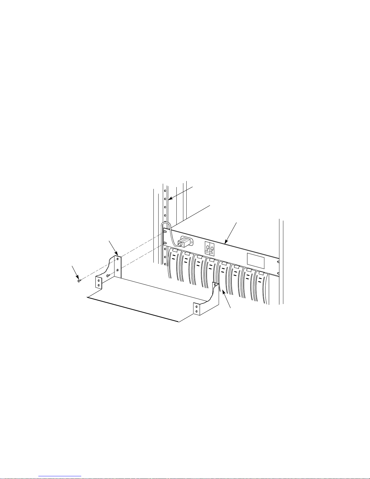
1. If CDU A is mounted in the position just above the upper-most shelf in the
rear of the cabinet, support the CDU in position against the rear vertical
cabinet rails while removing its mounting screws, as shown in Figure 6–5.
If the position just above the upper-most shelf is open, install four U-nuts on
the vertical cabinet rails, as shown in Figure 6–6.
2. Position the air separation panel against the front panel of CDU A or the four
U-nuts, as shown in either Figure 6–5 or 6–6, respectively.
3. Fasten the air separation panel (along with CDU A, if appropriate) to the
rear vertical cabinet rails with four screws, as shown.
Figure 6–5 Rear Air Separation Panel Installation (Shelf installed directly below CDU A)
REAR VERTICAL
CABINET RAIL
CDU A
AIR
SEPARATION
PANEL
CDU MOUNTING
SCREW
(4 PLACES)
UPPER-MOST
SHELF
CXO-3929A-MC
6–8 Installing StorageWorks Shelves
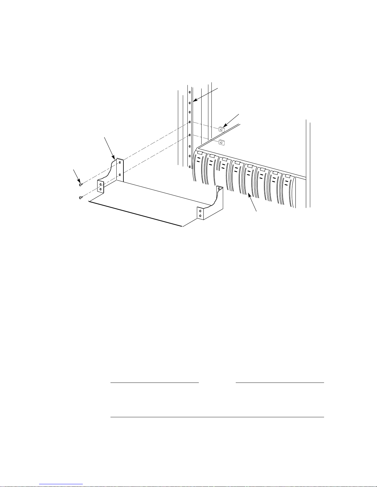
Figure 6–6 Rear Air Separation Panel Installation (Empty shelf position directly below CDU A)
REAR VERTICAL
CABINET RAIL
U-NUT, 10-32
AIR
SEPARATION
PANEL
CDU MOUNTING
SCREW
(4 PLACES)
(4 PLACES)
UPPER-MOST
SHELF
6.6 Reinstalling Exterior Cabinet Panels
Once the cabinet rack space is configured as desired, the exterior cabinet panels
may be reinstalled. Refer to Figure 6–1 and reinstall the exterior cabinet panels
as follows:
1. Position a side panel against the cabinet with the lip above the upper hanger
clips just over the upper edge of the side of the cabinet.
2. Ensure that the entire surface of the side panel rests firmly against the side
of the cabinet.
3. Allow the panel to slide downward, catching the two hanger clips as it moves.
4. Install the side panel bolts into the side panel through the holes in the top
side rails of the cabinet.
5. Repeat steps 1 through 4 to install the other side panel.
6. Locate the four inset nylon snap fasteners on the top cabinet rails.
WARNING
The top cover is heavy and awkward to lift. Installing it is a twoperson task. Failure to use sufficient personnel may result in injury or
equipment damage.
CXO-3935A-MC
7. Position the top cover over the cabinet. Position the cover as shown in
Figure 6–1 such that the front end of the panel with the shorter overhang is
oriented toward the rear of the cabinet.
Installing StorageWorks Shelves 6–9

8. Align the pins on the underside of the top cover with the inset nylon fasteners
on the top cabinet rails.
WARNING
Be careful not to catch your fingers between the cabinet and the top panel
when snapping the panel to the cabinet.
9. Lower the cover onto the cabinet and press it down, ensuring that the pins
snap into the top panel fasteners.
10. If the cabinet was moved to access the side panels, place it in its original
position.
6–10 Installing StorageWorks Shelves

Installing TZLX-Series Tape Drives
This chapter describes the mounting and power cabling of TZLX-series tape
drives in SH043-series cabinets.
7.1 General Installation Considerations
The TZLX-series tape drive is mounted in the SH043 cabinet with one chassis
rail, as shown in Figure 7–1. The chassis rail is attached to the cabinet’s internal
vertical rails, and it supports the TZLX-series tape drive from one side. Grooves
machined into the side of the tape drive enclosure mate with flanges along the
sides of the chassis rail, allowing the tape drive to be slid onto the chassis rail
from the front of the cabinet. Once installed, the tape drive enclosure extends
from the front to the rear of the SH043 cabinet.
Two TZLX-series tape drives can be mounted side-by-side at a given vertical
position in the cabinet. The chassis rail hardware is the same for both the
left and right mounting positions. Only the orientation of the hardware differs
between the two mounting positions. There is no mechanical connection between
two tape drives mounted side-by-side in the cabinet.
In situations where only one TZLX-series tape drive is being installed at a given
vertical position in the cabinet, the tape drive must be installed in the right
mounting position. This will ensure that the front panel of the tape drive mates
with the correct opening in the tape bezel in the cabinet door. A filler panel in
the tape bezel covers the left mounting position in this case.
7
WARNING
While working in the cabinet interior, ac power must be removed from
cabinet components. Failure to do so may result in personnel injury as a
result of electric shock.
Prior to performing any of the procedures in this chapter, remove ac power from
cabinet components. If the cabinet is installed and operating, spin down all disk
drives and halt all tape drives in the cabinet. Switch the circuit breaker on the
front panel of the cabinet’s CDU(s) to the(OFF) position.
Installing TZLX-Series Tape Drives 7–1

Figure 7–1 TZLX-Series Tape Drive Installation
CABINET
CHASSIS
RAIL
TAPE
BEZEL
TZLx-SERIES
TAPE DRIVE
(LEFT POSITION)
TZLx-SERIES
TAPE DRIVE
(RIGHT POSITION)
7.2 Accessing the Cabinet Rack Space
TZLX-series tape drives can normally be installed without removing cabinet side
panels. To route the cabling in configurations where access to the interior of the
cabinet is limited, however, cabinet side panels may need to be removed. Sections
7.2.1 and 7.8 present procedures for removing and replacing exterior cabinet
panels.
The front and rear cabinet doors are held closed by door locks mounted on each
door. The locks are released by turning counterclockwise with a 5/32-inch hex
wrench.
CXO-3958A-MC
7–2 Installing TZLX-Series Tape Drives
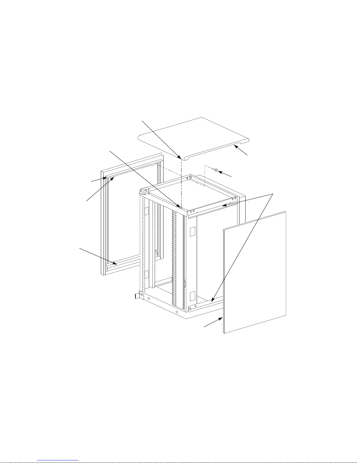
7.2.1 Removing the Cabinet Side Panels
As shown in Figure 7–2, there are three side panel hanger clips on each side
of the cabinet. A matching set of hanger clips are attached to each side panel.
Remove the side panels as follows:
Figure 7–2 Cabinet Side Panel Removal and Installation
FASTENER
PIN
(4 PLACES)
NYLON SNAP
FASTENER
(4 PLACES)
TOP COVER
UPPER
SIDE PANEL
HANGER
CLIP
LOWER
SIDE PANEL
HANGER
CLIP
LIP
M6x40mm BOLT
(4 PLACES)
SIDE PANEL
HANGER
CLIPS
CABINET
FRONT
SIDE PANEL
NOTE: FRONT AND REAR DOORS NOT SHOWN FOR CLARITY
CXO-3899A-MC
Installing TZLX-Series Tape Drives 7–3

1. Move the cabinet away from adjacent enclosures as necessary.
2. Loosen the top cover by pushing up on its front and rear edges until it snaps
free of its fasteners.
The top cover is heavy and awkward to lift. Removing it is a twoperson task. Failure to use sufficient personnel may result in injury or
equipment damage.
3. Using two persons, lift the top cover from the cabinet and set it aside.
4. Remove the bolts attaching the side panels to the top side rails of the cabinet.
5. Grasp a panel along its front and rear edges and lift up until the hanger clips
disengage. Lift the panel away from the cabinet.
6. Repeat the previous step to remove the other panel.
7.3 Chassis Rail Installation
To allow the length of the chassis rail to be adjusted to fit the cabinet, one end of
the rail is extendable using a sliding rail bracket. Two round standoffs are used
to locate the chassis rail along the vertical cabinet rails. The round standoffs are
inserted into front and rear chassis rail locating holes to position the chassis rail
while it is fastened to the cabinet.
WARNING
Chassis rail component assembly and installation procedures for both left and
right tape drive mounting positions are presented in Sections 7.3.1, 7.3.2, and
7.3.3.
Two small ESD grounding posts are provided with the cabinet. One is
located on a front vertical cabinet rail, and one on a rear rail. Should an
ESD grounding post interfere with the installation of the chassis rail,
move the post out of the way to any free hole on the cabinet.
7.3.1 Chassis Rail Assembly
Before the chassis rail components can be mounted in the cabinet, they must be
assembled. Assemble the chassis rail components as follows (see Figure 7–3):
1. Position the rail bracket against the chassis rail, as shown in the illustration.
2. Fasten the rail bracket to the chassis rail with the unbeveled nut bar and four
screws, as shown. Leave the screws loose enough to allow the rail bracket to
be moved along the chassis rail.
3. Install a U-nut in the groove near the end of each of the beveled nut bars.
The flat side of the U-nuts must be installed on the beveled side of the nut
bar.
Note
4. Install the beveled nut bars on the chassis rail and rail bracket, using the
round standoffs to hold them in place. The beveled side of the nut bars must
face the flanges on the chassis rail and rail bracket.
7–4 Installing TZLX-Series Tape Drives

5. The chassis rail assembly is now ready to be installed in the cabinet.
Figure 7–3 Chassis Rail Assembly
ROUND
STANDOFF
U-NUT, 10-32
(2 PLACES)
U
CHASSIS
RAIL
SCREW, 10-32
FH
(4 PLACES)
NUT BAR,
BEVELED
(2 PLACES)
RAIL
BRACKET
P
7.3.2 Right Position Chassis Rail Assembly Installation
Install the chassis rail assembly in the right position within the cabinet as follows
(see Figure 7–4):
WARNING
NUT BAR,
UNBEVELED
ROUND
STANDOFF
CXO-3934A-MC
Cabinet rail edges may be sharp and can slice or abrade skin or cable
insulation.
1. Turn the cabinet power off as described in Section 7.1.
2. Determine the correct tape drive mounting locations and corresponding
cabinet rail mounting holes for the chassis rail assembly. Refer to the chapter
in this document pertaining to your specific cabinet configuration for this
information. The tape mounting hole specified for each position is the chassis
rail locating hole shown in Figure 7–4.
Installing TZLX-Series Tape Drives 7–5

Figure 7–4 Right Position Chassis Rail Assembly Installation
REAR VERTICAL
REAR
CHASSIS
RAIL
LOCATING
HOLE
ROUND
STANDOFF
(2 PLACES)
CABINET RAIL
INNER
FLANGE
U-NUT, 10-32
(4 PLACES)
INNER
FLANGE
U
P
FRONT VERTICAL
CABINET RAIL
OUTER
FLANGE
U-NUT, 10-32
(2 PLACES)
FRONT
CHASSIS
RAIL
LOCATING
HOLE
SCREW, 10-32
SEMS
(4 PLACES)
Use care in supporting the chassis rail assembly. It is heavy and awkward
to position within the cabinet. If possible, use two persons to support and
position the chassis rail assembly. The chassis rail assembly may cause
personnel injury and equipment damage if dropped during installation.
CHASSIS
RAIL ASSEMBLY
RAIL
BRACKET
WARNING
WASHER, LOCK
10-32, INTERNAL
(6 PLACES)
SCREW, 10-32
HEX CAP
(6 PLACES)
CXO-3924A-MC
7–6 Installing TZLX-Series Tape Drives

Note
To ensure proper alignment of the chassis rail assembly, use care to
position the round standoffs in the correct front and rear chassis rail
locating holes.
3. From the front of the cabinet, position the chassis rail assembly at the correct
mounting holes, as shown. Ensure that the rail bracket is positioned toward
the front of the cabinet, and that the arrow on the rail bracket points up.
4. Insert the rear round standoff into the rear chassis rail locating hole.
5. Support the chassis rail against the rear vertical cabinet rail and maintain
the rear round standoff in its locating hole. Extend the rail bracket to insert
the front round standoff into its correct front chassis rail locating hole.
6. Using the shelf bracket as a template, mark the four U-nut mounting holes
on the inner flanges of both the front and rear vertical cabinet rails. Make
sure to use the correct set of holes in the chassis rail.
7. Temporarily remove the chassis rail assembly and install four U-nuts along
the inner flanges of the front and rear vertical cabinet rails at the holes
marked in step 6.
8. Reposition the chassis rail assembly as directed in steps 3 through 5.
9. Fasten the chassis rail to the inner flanges of the front and rear vertical
cabinet rails with four screws, as shown.
10. Fasten the rail bracket to the front vertical cabinet rail with its beveled nut
bar and three screws, as shown.
11. Fasten the chassis rail to the rear vertical cabinet rail with its beveled nut
bar and three screws, as shown.
12. Tighten the screws fastening the rail bracket to the chassis rail.
13. Install two U-nuts along the outer flange of the front vertical cabinet rail.
Install one U-nut at the hole just above the front chassis rail locating hole
and the other at the eighth hole below the locating hole.
7.3.3 Left Position Chassis Rail Assembly Installation
Note
Install the chassis rail assembly in the left mounting position only if
a tape drive is also installed in the right position. The front cabinet
door tape bezel openings are designed to allow a single tape drive to be
installed only in the right position.
Install the chassis rail assembly in the left position within the cabinet as follows
(see Figure 7–5):
WARNING
Cabinet rail edges may be sharp and can slice or abrade skin or cable
insulation.
Installing TZLX-Series Tape Drives 7–7

1. Turn the cabinet power off as described in Section 7.1.
2. Determine the correct tape drive mounting locations and corresponding
cabinet rail mounting holes for the chassis rail assembly. Refer to the chapter
in this document pertaining to your specific cabinet configuration for this
information. The tape mounting hole specified for each position is the chassis
rail locating hole shown in Figure 7–5.
Figure 7–5 Left Position Chassis Rail Assembly Installation
REAR VERTICAL
CABINET RAIL
U-NUT, 10-32
(2 PLACES)
FRONT
CHASSIS
RAIL
LOCATING
HOLE
SCREW, 10-32
HEX CAP
(6 PLACES)
OUTER
FLANGE
WASHER, LOCK
10-32, INTERNAL
(6 PLACES)
FRONT VERTICAL
CABINET RAIL
INNER
FLANGE
U-NUT, 10-32
(4 PLACES)
INNER
FLANGE
CHASSIS
RAIL ASSEMBLY
REAR
CHASSIS
RAIL
LOCATING
HOLE
SCREW, 10-32
SEMS
(4 PLACES)
ROUND
STANDOFF
(2 PLACES)
P
U
RAIL
BRACKET
CXO-3923A-MC
Use care in supporting the chassis rail assembly. It is heavy and awkward
to position within the cabinet. If possible, use two persons to support and
position the chassis rail assembly. The chassis rail assembly may cause
personnel injury and equipment damage if dropped during installation.
7–8 Installing TZLX-Series Tape Drives
WARNING

Note
To ensure proper alignment of the chassis rail assembly, use care to
position the round standoffs in the correct front and rear chassis rail
locating holes.
3. From the rear of the cabinet, position the chassis rail assembly at the correct
mounting holes, as shown. Ensure that the rail bracket is positioned toward
the rear of the cabinet, and that the arrow on the rail bracket points up.
4. Insert the front round standoff into the front chassis rail locating hole.
5. Support the chassis rail assembly against the front vertical cabinet rail and
maintain the front round standoff in its locating hole. Extend the rail bracket
to insert the rear round standoff into its correct rear chassis rail locating hole.
6. Using the chassis rail as a template, mark the four U-nut mounting holes on
the inner flanges of both the front and rear vertical cabinet rails. Make sure
to use the correct set of holes in the chassis rail.
7. Temporarily remove the chassis rail assembly and install four U-nuts along
the inner flanges of the front and rear vertical cabinet rails at the holes
marked in step 6.
8. Reposition the chassis rail assembly as directed in steps 3 through 5.
9. Fasten the chassis rail assembly to the inner flanges of the front and rear
vertical cabinet rails with four screws, as shown.
10. Fasten the rail bracket to the rear vertical cabinet rail with its beveled nut
bar and three screws, as shown.
11. Fasten the chassis rail to the front vertical cabinet rail with its beveled nut
bar and three screws, as shown.
12. Tighten the screws fastening the rail bracket to the chassis rail.
13. Install two U-nuts along the outer flange of the front vertical cabinet rail.
Install one U-nut at the hole just above the front chassis rail locating hole
and the other at the eighth hole below the locating hole.
7.4 Mounting the TZLX-Series Tape Drive Enclosure
Once the chassis rail is installed in the cabinet, the tape drive enclosure can be
mounted on it. Mount the TZLX-series tape drive to the chassis rail as follows:
Note
The lock down brackets are mirror images of each other, and they are
identified as the -01 and -02 versions. They must be installed with the
orientation shown in the illustration.
1. Install the the two lock down brackets on the side of the tape drive enclosure
near the front end, as shown in either Figure 7–6 or 7–7. Figure 7–6 shows
the installation for the right mounting position, and Figure 7–7 shows the
installation for the left mounting position.
Installing TZLX-Series Tape Drives 7–9

Figure 7–6 Right Position Tape Drive Mounting
SCREW, 10-32
HEX CAP
(4 PLACES)
WASHER, 10-32
LOCK
(2 PLACES)
WASHER, 10-32
FLAT
(2 PLACES)
LOCK DOWN
BRACKET
(-02)
FRONT VERTICAL
CHASSIS RAIL
U-NUT, 10-32
(2 PLACES)
(REF)
TAPE DRIVE
ENCLOSURE
(FRONT)
WASHER, 10-32
LOCK
(4 PLACES)
NOTE: TAPE DRIVE INTERNAL COMPONENTS NOT SHOWN FOR CLARITY.
SCREW, 10-32
HEX CAP
(4 PLACES)
LOCK DOWN
BRACKET
(-01)
CXO-3918A-MC
7–10 Installing TZLX-Series Tape Drives

Figure 7–7 Left Position Tape Drive Mounting
FRONT VERTICAL
CABINET RAIL
U-NUT, 10-32
(2 PLACES)
(REF)
LOCK DOWN
BRACKET
(-01)
WASHER, 10-32
FLAT
(2 PLACES)
WASHER, 10-32
LOCK
(2 PLACES)
SCREW, 10-32
HEX CAP
(2 PLACES)
TAPE DRIVE
ENCLOSURE
LOCK DOWN
BRACKET
(-02)
SCREW, 10-32
HEX CAP
(4 PLACES)
NOTE: TAPE DRIVE INTERNAL COMPONENTS NOT SHOWN FOR CLARITY.
WASHER, 10-32
LOCK
(4 PLACES)
(FRONT)
CXO-3919A-MC
WARNING
Use two persons to lift the TZLX-series tape drive. The unit is heavy and
awkward to lift. Failure to use two persons to lift the tape drive may
result in injury or damage to equipment.
2. From the front of the cabinet and using two persons, position the tape drive
such that the machined grooves in the side of the tape drive enclosure mate
with the upper and lower edges of the chassis rail.
Installing TZLX-Series Tape Drives 7–11

Use care when sliding the tape drive into the cabinet. Do not allow the
tape drive enclosure to pull or pinch cables that may be routed through
the cabinet interior. Failure to use care when mounting the tape drive
may result in equipment damage.
3. Slide the tape drive onto the chassis rail until the lockdown brackets contact
the U-nuts on the front vertical cabinet rail.
4. Fasten the lock down brackets to the front vertical chassis rail with two hex
cap screws, as shown in Figure 7–6 or 7–7.
7.5 Installing the Power Cord
AC power for the TZLX-series tape drive is obtained from CDU A. Connect the
female end of the tape drive’s power cord to the power connector on the rear
panel of the drive (see Figure 7–8.) Route the power cord inside the cabinet to
CDU A, avoiding signal cabling where possible. Connect the male end to a free
power connector on the rear panel of the CDU. Switch the power switch on the
rear panel of the tape drive to the(ON) position to allow the CDU to control the
unit’s power.
CAUTION
7–12 Installing TZLX-Series Tape Drives

Figure 7–8 TZLX-Series Tape Drive Rear Panel
SCSI-2
CONNECTORS
AC POWER
SWITCH
AC RECEPTACLE
CXO-3932A-MC
7.6 SCSI–2 Signal Cabling
Refer to the StorageWorks Family Configuration Guide and the StorageWorks
Family User ’s Guide for details on the selection of SCSI–2 cables and their
connection to the TZLX-series tape drive.
7.7 Installing the Cabinet Door Tape Bezel Kit
To allow operator access to the TZLX tape drive, the front cabinet door tape
bezel kit must be installed. To install the tape bezel kit, see the Instructions for
Installation of the Tape Bezel Kit on SF400 Series Cabinets provided with the kit.
The SF400 installation instructions also apply to SH043-series cabinets.
If the tape bezel kit is already installed, you need only remove its filler panel to
accomodate a tape drive in the left mounting position.
Installing TZLX-Series Tape Drives 7–13

7.8 Reinstalling Exterior Cabinet Panels
Once the cabinet rack space is configured as desired, the exterior cabinet panels
may be reinstalled. Refer to Figure 7–2 and reinstall the exterior cabinet panels
as follows:
1. Position a side panel against the cabinet with the lip above the upper hanger
clips just over the upper edge of the side of the cabinet.
2. Ensure that the entire surface of the side panel rests firmly against the side
of the cabinet.
3. Allow the panel to slide downward, catching the three hanger clips as it
moves.
4. Install the side panel bolts into the side panel through the holes in the top
side rails of the cabinet.
5. Repeat steps 1 through 4 to install the other side panel.
6. Locate the four inset nylon snap fasteners on the top cabinet rails.
WARNING
The top cover is heavy and awkward to lift. Installing it is a twoperson task. Failure to use sufficient personnel may result in injury or
equipment damage.
7. Position the top cover over the cabinet. Position the cover as shown in
Figure 7–2 such that the end of the panel with the shorter overhang is
oriented toward the front of the cabinet.
8. Align the pins on the underside of the top cover with the inset nylon fasteners
on the top cabinet rails.
WARNING
Be careful not to catch your fingers between the cabinet and the top panel
when snapping the panel to the cabinet.
9. Lower the cover onto the cabinet and press it down, ensuring that the pins
snap into the top panel fasteners.
10. If the cabinet was moved to access the side panels, place it in its original
position.
7–14 Installing TZLX-Series Tape Drives

This chapter discusses the configuration of primary power within SH043-series
cabinets. Additional information on power configuration options can be found in
Section 1.3.
8.1 General Considerations
While working in the cabinet interior, ac power must be removed from
cabinet components. Failure to do so may result in personnel injury as a
result of electric shock.
Prior to performing any of the procedures in this chapter, remove ac power from
the cabinet components. If the cabinet is installed and operating, spin down all
disk drives and halt all tape drives in the cabinet. Switch the circuit breaker on
the front panel of the cabinet’s cable distribution units (CDUs) to the
position.
Power Configuration
WARNING
8
(OFF)
8.2 Cable Distribution Units
The 887–E CDU is used with SH043-series cabinets and is designed for both
230 volt, 50 Hz and 120 volt, 60 Hz applications. The unit provides ac power
to the cabinet’s components via 12 Molex output connectors on its rear panel.
Two International Electrotechnical Commission (IEC) output connectors are also
provided for utility purposes.
If the leakage current of the cabinet is above 3.5 mA after installation,
Digital recommends that power cables with industrial type B, IEC 950
connectors be installed. Failure to reduce the leakage current can result
in equipment performance degradation and personnel injury due to
electric shock.
Table 8–1 lists the power cables used with the 887–E CDU.
WARNING
Power Configuration 8–1

Table 8–1 CDU Power Cable Variations
Cable Part No.† Country Usage Comments‡
17–01255–01 Europe, Japan IEC 309 plug and
17–00083–57 United States NEMA 5–20P twist-lock
†The SH043–ZZ cabinet version for Europe and Japan is shipped with the either the 17–01255–01 or
17–00083–57 power cable, depending upon customer requirements.
‡All power cables are supplied with a female plug compatible with the IEC input connector on the
front panel of the CDU.
8.3 Utility Power Cord
Each SH043 cabinet is furnished with one additional power cord for the purpose
of powering monitors, printers, or other devices. The power cord is connected to
the rear panel of the CDU and may be found coiled up in the base of the cabinet.
8.4 Single CDU Configurations
Using one CDU, cabinet power can be configured with both single and dual power
supplies in each shelf. Refer to Sections 1.3.1 and 1.3.2 for further information on
these configurations.
8.4.1 Single Cabinet Power Configuration
Unless options are specified, SH043-series cabinets are shipped with a single
CDU and single-shelf power supplies. For ease of upgrade, the cabinet is supplied
with 10 black and 10 gray preinstalled ac power cords. One black and one gray
power cord is routed to each usable front and rear shelf position. These cords are
used to supply ac power to shelves as they are added to the cabinet. The black
cord at each newly added shelf’s mounting position needs only to be plugged into
the shelf ’s power supply to complete the shelf’s installation.
cordage (220/240 volt)
plug (120 volt)
8.4.2 Dual Shelf Power Configuration
In the dual shelf power configuration, a second ac power supply is necessary for
each shelf. (Refer to Figure 1–5.) Configure each shelf for dual ac power supplies
as follows:
1. Power the cabinet down as described in Section 8.1.
2. Plug in a second ac power supply (B) next to the existing ac power supply (A)
in each shelf.
3. Plug the gray ac power cord at each shelf position into the connector on the
newly added ac power supply.
4. Connect the CDU primary power cable to its power source.
5. Using the procedures appropriate to your system, turn on the cabinet and
initialize it.
8–2 Power Configuration

8.5 Dual Cabinet Power Configuration
The dual cabinet power configuration requires two CDUs for power distribution.
The second CDU (CDU B) is installed immediately above CDU A in the rear of
the cabinet. Refer to the StorageWorks SH043-Series Data Center Cabinet Cable
Distribution Unit Installation Guide for procedures pertaining to the installation
of dual CDUs. The installation guide is shipped as part of the dual power option
kit.
Power Configuration 8–3


Environmental Stabilization
A.1 Environmental Stabilization
To ensure proper operation of Digital storage devices, the StorageWorks building
block (SBB) temperature must be within 18–29°C (65–85°F). Table A–1 specifies
the time required to thermally stabilize SBBs based on the ambient shipping
temperature.
Table A–1 Thermal Stabilization Specifications
Ambient
Temperature
Range °C
60 to 66 140 to 151 3 hours
50 to 59 122 to 139 2 hours
40 to 49 104 to 121 1 hour
30 to 39 86 to 103 30 minutes
18 to 29 65 to 85 None
10 to 17 50 to 64 30 minutes
0 to 9 32 to 49 1 hour
–10 to –1 14 to 31 2 hours
–20 to –11 –4 to 13 3 hours
–30 to –21 –22 to –5 4 hours
–40 to –31 –40 to –21 5 hours
Ambient
Temperature
Range °F
A
Minimum
Stabilization
Time
CAUTION
Always stabilize storage devices in the operating environment prior to
installation or operation. Otherwise, the media or associated electronics
may be damaged when power is applied to the unit.
If condensation is visible on the outside of the storage device:
Stabilize the device and the SBB in the operating environment for 6 hours or
until the condensation is no longer visible, whichever is longer. Do not insert
the storage device into the shelf until it is fully stabilized.
If condensation is not visible on the outside of the storage device:
Thermally stabilize the device for the amount of time specified in Table A–1.
Environmental Stabilization A–1


Glossary
ac power supply
A power supply designed to produce dc power from an ac input.
air separation panel
A small baffle that mounts just above the upper-most shelf in a cabinet to prevent
heated cabinet air from being drawn down between the cabinet door and the
shelf.
American National Standards Institute
See ANSI.
ANSI
American National Standards Institute. An organization that develops and
publishes electronic and mechanical standards.
blower
An airflow device mounted in a StorageWorks shelf.
cabinet
The enclosure portion of the SH043-series cabinet, including the exterior panels
and the doors. This term may also be used to refer to an enclosure configured
with internal storage components.
cable distribution unit
See CDU.
CDU
Cable distribution unit. The power entry device for StorageWorks SH043-series
cabinets. The unit provides the connections necessary to distribute ac power to
cabinet shelves and fans.
chassis rail
A slide rail used to support the TZLX-series tape drive within the cabinet.
controller
A hardware/software device that manages peripheral device communications on
behalf of a host system.
data center cabinet
A generic reference to the large cabinets, such as the SW800-series, in which
StorageWorks components can be mounted.
Glossary–1

dual cabinet power configuration
A cabinet ac power configuration in which two ac sources and two ac power
supplies are used to supply dc power to the cabinet’s SBB shelves.
dual shelf power configuration
A cabinet ac power configuration in which one ac source and two ac power
supplies are used to supply dc power to the cabinet’s SBB shelves.
fan
An airflow device mounted in a StorageWorks cabinet.
filler panel
A sheet metal or plastic panel used to cover unused mounting areas in
StorageWorks cabinets and shelves.
host
The primary or controlling computer to which a storage subsystem is attached.
SBB
StorageWorks building block. The basic building block of the StorageWorks
product line. A device conforming to StorageWorks shelf mechanical and
electrical standards and installed in a 3½-inch or 5¼-inch carrier. Typical SBBs
are disk drives, tape drives, optical storage devices, and CD-ROMs.
SBB shelf
A StorageWorks shelf, such as the SHDZZ–ZZ, designed to house plug-in SBB
modules.
SCSI–2
Small Computer System Interface 2. An ANSI interface standard that defines
the physical and electrical parameters of a parallel I/O bus used to connect a
controller with up to 7 devices. The StorageWorks implementation of SCSI uses
the SCSI-2 standard to provide for the synchronous transfer of 8-bit data at rates
of up to 10 MB/s.
shelf brackets
Sheet metal components designed to attach and position StorageWorks shelves in
their associated enclosures.
single cabinet power configuration
A cabinet ac power configuration in which only one ac source and one ac power
supply is used to supply dc power to the cabinet’s SBB shelves.
skirt
A trim panel designed to mount around the base of the cabinet.
Small Computer System Interface 2
See SCSI–2.
Glossary–2

StorageWorks
Digital’s line of data storage products that allows customers to design and
configure their own storage subsystems. StorageWorks products consist of
modular storage and power components and the enclosures necessary to house
them. Storage devices and array controllers can be integrated to form storage
subsystems.
StorageWorks building block
See SBB.
Glossary–3


Index
A
Air separation panels, 1–10, 6–1
in SH043 controller/storage cabinets, 5–4
in SH043 storage-only cabinets, 4–3
installation, 6–7
C
Cabinet
cooling, 1–10
inspecting, 3–8
leveling, 3–5, 3–7
placement of, 3–6
powering, 3–9
ramp unloading procedures, 3–3
site preparation, 2–1
unloading, 3–3
unpacking, 3–1
Cabinet components, 1–4
cabinet, 1–4
CDUs, 1–4
controller shelves, 1–4
SBB shelves, 1–4
SBBs, 1–4
shelf brackets, 1–4
TZLX-series tape drives, 1–6
Cable distribution units
power cables used, 8–1
type used, 8–1
Cable routing, general
in SH043 controller/storage cabinets, 5–6
in SH043 storage-only cabinets, 4–4
Cooling, cabinet, 1–10
F
Filler panels, 1–10, 6–1
in SH043 controller/storage cabinets, 5–4
in SH043 storage-only cabinets, 4–3
installation, 6–6
G
Grounding, equipment, 2–2
H
Host SCSI–2 signal cable routing
in SH043 controller/storage cabinets, 5–4
I
Inspection
of cabinet installation, 3–8
of ramps, 3–3
of shipped equipment, 3–1
Installing
base trim kit, 3–7
StorageWorks shelves, 6–1
TZLX-series tape drives, 7–1
L
Leveling, cabinet, 3–7
O
Overview, 1–1
D
Description, of SH043 cabinet, 1–1
Door locks, 6–2
E
Environmental stabilization, A–1
Exterior panels
reinstalling, 6–9, 7–14
removal, 6–2
P
Placement, of cabinet, 3–6
Power configuration
of SH043 controller/storage cabinets, 5–4
of SH043 storage-only cabinets, 4–4
Power configurations, 1–7, 8–1
dual cabinet power configuration, 1–9, 8–3
dual shelf power configuration, 1–8, 8–2
single cabinet power configuration, 1–7, 8–2
Index–1

Power receptacles, site, 2–1
Power system survey, 2–3
Powering up, cabinet, 3–9
R
Ramps
inspection, 3–3
unloading, 3–3
Removal, cabinet from pallet, 3–3
S
SCSI–2 cable lengths
in SH043 controller/storage cabinets, 5–5
SCSI–2 cable routing
in SH043 controller/storage cabinets, 5–5
in SH043 storage-only cabinets, 4–4
SCSI–2 configurations, standard
in SH043 controller/storage cabinets, 5–5
SH043 controller/storage cabinets
cable routing, general, in, 5–6
configuration of, 5–1
host SCSI–2 signal cable routing in, 5–4
power configuration of, 5–4
SCSI–2 cable lengths in, 5–5
SCSI–2 cable routing in, 5–5
shelf locations in, 5–1, 5–3
standard SCSI–2 configurations in, 5–5
TZLX-series tape drive locations in, 5–3
SH043 storage-only cabinets
cable routing, general, in, 4–4
configuration of, 4–1
power configuration of, 4–4
SCSI–2 cable routing in, 4–4
shelf locations in, 4–1, 4–2
signal cable routing in, 4–4
TZLX-series tape drive locations in, 4–2
Shelf locations
in SH043 controller/storage cabinets, 5–1, 5–3
in SH043 storage-only cabinets, 4–1, 4–2
Shelf SCSI–2 cable selection and connection
in SH043 controller/storage cabinets, 5–5
in SH043 storage-only cabinets, 4–4
Shelves, StorageWorks
installation of, 6–1, 6–3
Side panels
reinstalling, 6–9, 7–14
removal, 7–2
removing, 6–2, 7–3
Signal cable routing
in SH043 storage-only cabinets, 4–4
Site preparation, 2–1
Specifications
environmental stabilization, A–1
SH043 cabinet, 1–1
Stabilization, thermal, 3–1
T
Thermal stabilization, A–1
Trim kit, installing, 3–7
TZLX-series tape drives
chassis rail, 7–1
chassis rail installation, 7–4
installation of, 7–1
locations in SH043 controller/storage cabinets,
5–3
locations in SH043 storage-only cabinets, 4–2
power cord installation, 7–12
SCSI–2 signal cabling, 7–13
tape bezel, 7–1
tape bezel kit installation, 7–13
tape drive enclosure mounting, 7–9
U
Unloading, cabinet, 3–3
Unpacking, cabinet, 3–1
Index–2
 Loading...