

Stoelting O231-18I2F Operators Manual

Model O231-I2F
OPERATORS MANUAL
Manual No. 513717 Rev.1


This manual provides basic information about the machine. Instructions and suggestions are
given covering its operation and care.
The illustrations and specifi cations are not binding in detail. We reserve the right to make
changes to the machine without notice, and without incurring any obligation to modify or provide new parts for machines built prior to date of change.
DO NOT ATTEMPT to operate the machine until instructions and safety precautions in this
manual are read completely and are thoroughly understood. If problems develop or questions
arise in connection with installation, operation, or servicing of the machine, contact Stoelting.
stoeltingfoodservice.com
Stoelting Foodservice Equipment
502 Highway 67
Kiel, WI 53042-1600
U.S.A.
White Glove Service Network
Phone: 888.319.9549
© 2018 Stoelting

A Few Words About Safety
Safety Information
Read and understand the entire manual before
operating or maintaining Stoelting equipment.
This manual provides the operator with information
for the safe operation and maintenance of Stoelting
equipment. As with any machine, there are hazards
associated with their operation. For this reason safety
is emphasized throughout the manual. To highlight
specifi c safety information, the following safety defi ni-
tions are provided to assist the reader.
The purpose of safety symbols is to attract your attention to possible dangers. The safety symbols, and
their explanations, deserve your careful attention
and understanding. The safety warnings do not by
themselves eliminate any danger. The instructions
or warnings they give are not substitutes for proper
accident prevention measures.
If you need to replace a part, use genuine Stoelting
parts with the correct part number or an equivalent
part. We strongly recommend that you do not use
replacement parts of inferior quality.
Safety Alert Symbol:
This symbol Indicates danger, warning or caution.
Attention is required in order to avoid serious personal injury. The message that follows the symbol
contains important information about safety.
Signal Word:
Signal words are distinctive words used throughout
this manual that alert the reader to the existence and
relative degree of a hazard.
WARNING
The signal word “WARNING” indicates a potentially
hazardous situation, which, if not avoided, may result
in death or serious injury and equipment/property
damage.
CAUTION
The signal word “CAUTION” indicates a potentially
hazardous situation, which, if not avoided, may result
in minor or moderate injury and equipment/property
damage.
CAUTION
The signal word “CAUTION” not preceded by the
safety alert symbol indicates a potentially hazardous
situation, which, if not avoided, may result in equipment/property damage.
NOTE (or NOTICE)
The signal word “NOTICE” indicates information or
procedures that relate directly or indirectly to the
safety of personnel or equipment/property.

TABLE OF
CONTENTS
Section Description Page
1 Description and Specifi cations
1.1 Description ..................................................................................................1
1.2 Specifi cations .............................................................................................1
2 Installation Instructions
2.1 Safety Precautions .....................................................................................3
2.2 Shipment and Transit ..................................................................................3
2.3 Machine Installation ....................................................................................3
2.4 IntelliTec2™ Setup ......................................................................................4
3 Initial Set-Up and Operation
3.1 Operator’s Safety Precautions ...................................................................7
3.2 Operating Controls and Indicators ..............................................................7
3.3 Emptying the Freezing Cylinder .................................................................8
3.4 Disassembly of Machine Parts ...................................................................8
3.5 Cleaning Disassembled Parts ....................................................................9
3.6 Cleaning the Machine .................................................................................9
3.7 Assembling Machine ..................................................................................10
3.8 Sanitizing ....................................................................................................10
3.9 Freeze Down and Operation ......................................................................11
3.10 Mix Information ...........................................................................................12
4 Maintenance and Adjustments
4.1 Drive Belt Tension Adjustment ....................................................................13
4.2 Condenser Cleaning ...................................................................................13
4.3 Preventative Maintenance ..........................................................................13
4.4 Extended Storage .......................................................................................14
5 Troubleshooting
5.1 Error Codes ................................................................................................15
5.2 Troubleshooting - Error Codes ...................................................................15
5.3 Troubleshooting - Machine .........................................................................17
6 Replacement Parts
6.1 Decals and Lubrication ...............................................................................19
6.2 Auger Shaft and Faceplate Parts ...............................................................20

SECTION 1
INTRODUCTION
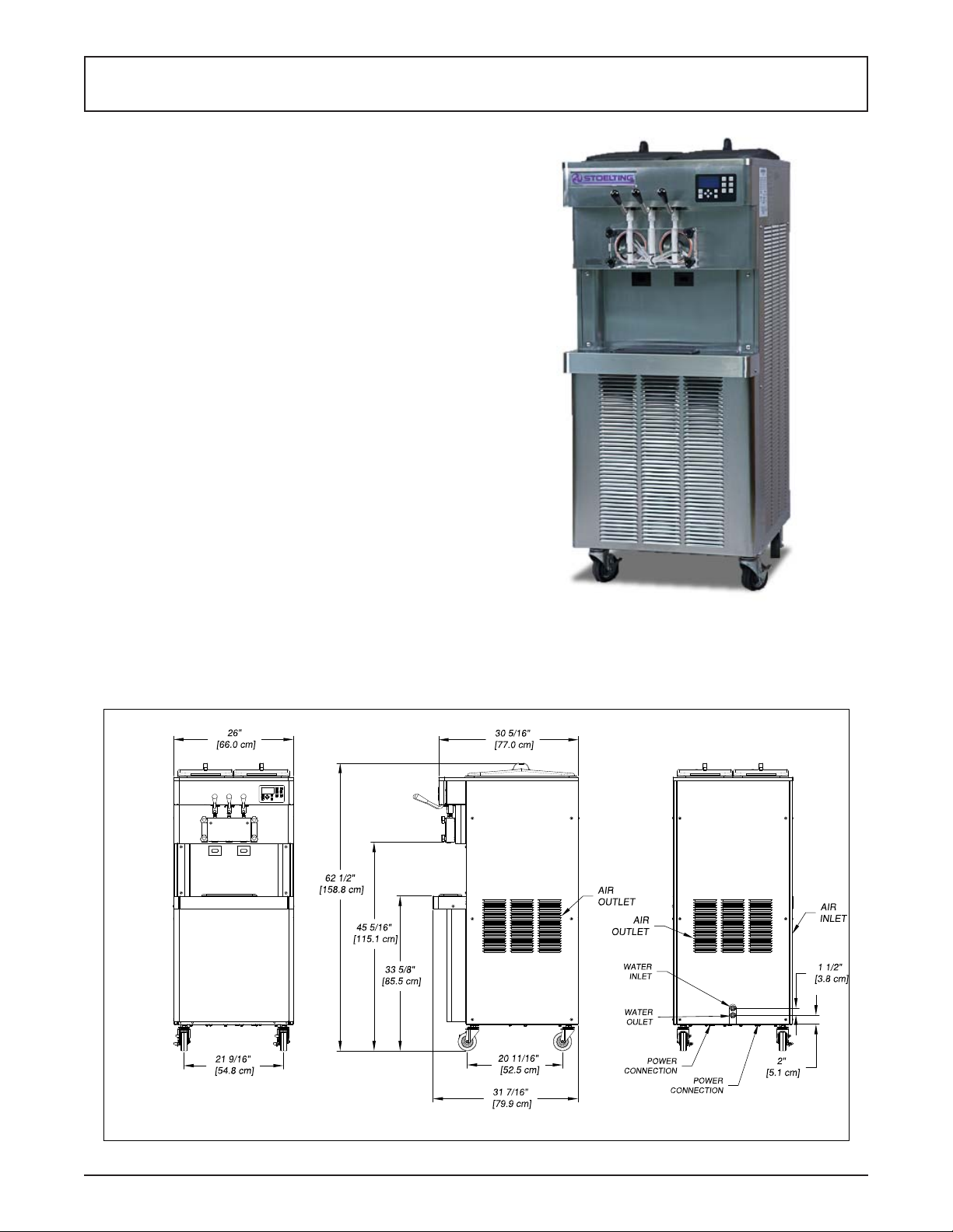
1.1 DESCRIPTION
The Stoelting O231-I2F fl oor machine is gravity fed. The
machine is equipped with the IntelliTec2 control which
provides a uniform product. The O231-I2F is designed to
operate with almost any type of commercial soft serve or
non-dairy mixes available, including: ice milk, ice cream,
yogurt, and frozen dietary desserts.
This manual is designed to assist qualifi ed service per-
sonnel and operators in the installation, operation and
maintenance of the Stoelting O231-I2F gravity machine.
1.2 SPECIFICATIONS
Figure 1-1 Model O231-I2F
Figure 1-2 Specifi cation
Operators Manual #513717 1 O231-I2F Model Machines

1.2 SPECIFICATIONS
O231-I2F Water Cooled O231-I2F Air Cooled
Dimensions Machine with crate Machine with crate
width
height
depth
Weight
Electrical 1 PH 3 PH 1 PH 3 PH
circuit ampacity
(per barrel)
26’’ (66,0 cm) 40-1/4’’ (102,2 cm) 26’’ (66,0 cm) 40-1/4’’ (102,2 cm)
62-1/2’’ (158,8 cm) 64-1/2’’ (163,8 cm) 62-1/2’’ (158,8 cm) 64-1/2’’ (163,8 cm)
31-1/2’’ (80,0 cm) 33-1/4’’ (84,5 cm) 31-1/2’’ (80,0 cm) 33-1/4’’ (84,5 cm)
640 lbs (290,2 kg) 730 lbs (331,1 kg) 640 lbs (290,2 kg) 730 lbs (331,1 kg)
26A minimum 19A minimum 27A minimum 20A minimum
overcurrent protection
device (per barrel)
Compressor
40A maximum 30A maximum 40A maximum 30A maximum
Freezing Cylinders - Two 12,000 Btu/hr (R-404A)
Storage - 1,300 Btu/hr Compressor (R-134a)
Drive Motor Two - 2 hp
Water cooled units require 1/2”
N.P.T. water and drain fi ttings with
2 inlets and 2 outlets or 1/2” N.P.T.
Cooling
water and drain fi ttings with 1 inlet
and 1 outlet.
Air cooled units require 3” (7,6 cm)
air space at back and sides.
Maximum water pressure of 130 psi.
Minimum water fl ow rate of 3 GPM.
Ideal EWT of 50°-70°F
Hopper Volume Two - 6.5 gallon (24,7 liters)
Freezing Cylinder
Volume
Two - 1 gallon (3,79 liters)
Operators Manual #513717 2 O231-I2F Model Machines
SECTION 2
INSTALLATION INSTRUCTIONS
2.1 SAFETY PRECAUTIONS
Do not attempt to operate the machine until the safety
precautions and operating instructions in this manual are
read completely and are thoroughly understood.
Take notice of all warning labels on the machine. The labels have been put there to help maintain a safe working
environment. The labels have been designed to withstand
washing and cleaning. All labels must remain legible for
the life of the machine. Labels should be checked periodically to be sure they can be recognized as warning labels.
If danger, warning or caution labels are needed, indicate
the part number, type of label, location of label, and quantity
required along with your address and mail to:
STOELTING
ATTENTION: Customer Service
502 Hwy. 67
Kiel, Wisconsin 53042
2.2 SHIPMENT AND TRANSIT
The machine has been assembled, operated and inspected
at the factory. Upon arrival at the fi nal destination, the
entire machine must be checked for any damage which
may have occurred during transit.
With the method of packaging used, the machine should
arrive in excellent condition. THE CARRIER IS RESPONSIBLE FOR ALL DAMAGE IN TRANSIT, WHETHER
VISIBLE OR CONCEALED. Do not pay the freight bill
until the machine has been checked for damage. Have
the carrier note any visible damage on the freight bill. If
concealed damage and/or shortage is found later, advise
the carrier within 10 days and request inspection. The
customer must place claim for damages and/or shortages
in shipment with the carrier. Stoelting, Inc. cannot make
any claims against the carrier.
2.3 MACHINE INSTALLATION
WARNING
TOOLS NEEDED
• Level
• Screwdrivers, wrenches, channel locks
• Straight edge
• Thermometer
PRIOR TO INSTALLATION
A. On the startup form, complete the following:
1. Buyer Information
2. Distributor Information
3. Authorized Service Provider Information
4. Verify with Store Operator Checklist
5. Freezer Confi guration Information
B. Prepare a USB fl ash drive with your service
contact information:
1. Locate a copy of the service contact fi le (info.
txt)
2. Modify the info.txt fi le with information from
your service company using the instructions
in the fi le.
3. Save the service contact fi le to the root level
of the USB fl ash drive (do not put the fi le into
any folder).
INSTALLATION
A. Uncrate the machine and install the casters.
Screw the casters into the threaded holes and
tighten them using a pair of channel locks. Set
the machine in place.
B. Accurate leveling is necessary for correct drainage
of the freezing cylinder and to ensure correct
overrun. Place a level on top of the machine
at each corner to check for level condition. If
adjustment is necessary, level the machine by
turning the bottom part of each caster in or out
then tighten the lock nut.
Installation must be completed by a qualifi ed
electrician/refrigeration specialist.
Incorrect installation may cause personal injury,
severe damage to the machine and will void factory warranty.
Installation of the machine involves moving the machine
close to its permanent location, removing all crating, setting in place, assembling parts, and cleaning.
Operators Manual #513717 3 O231-I2F Model Machines
 Loading...