

Stoelting O231 Owner’s Manual

Model O231
OPERATORS MANUAL
Manual No. 513645 May 2010


This manual provides basic information about the machine. Instructions and suggestions are
given covering its operation and care.
The illustrations and specifi cations are not binding in detail. We reserve the right to make
changes to the machine without notice, and without incurring any obligation to modify or provide new parts for machines built prior to date of change.
DO NOT ATTEMPT to operate the machine until instructions and safety precautions in this
manual are read completely and are thoroughly understood. If problems develop or questions
arise in connection with installation, operation, or servicing of the machine, contact Stoelting.
stoeltingfoodservice.com
Stoelting Foodservice Equipment
502 Highway 67
Kiel, WI 53042-1600
U.S.A.
Main Tel: 800.558.5807
Fax: 920.894.7029
Customer Service: 888.429.5920
Fax: 800.545.0662
Email: foodservice@stoelting.com
© 2014 PW Stoelting, LLC

A Few Words About Safety
Safety Information
Read and understand the entire manual before
operating or maintaining Stoelting equipment.
This manual provides the operator with information
for the safe operation and maintenance of Stoelting
equipment. As with any machine, there are hazards
associated with their operation. For this reason safety
is emphasized throughout the manual. To highlight
specifi c safety information, the following safety defi ni-
tions are provided to assist the reader.
The purpose of safety symbols is to attract your attention to possible dangers. The safety symbols, and
their explanations, deserve your careful attention
and understanding. The safety warnings do not by
themselves eliminate any danger. The instructions
or warnings they give are not substitutes for proper
accident prevention measures.
If you need to replace a part, use genuine Stoelting
parts with the correct part number or an equivalent
part. We strongly recommend that you do not use
replacement parts of inferior quality.
Safety Alert Symbol:
This symbol Indicates danger, warning or caution.
Attention is required in order to avoid serious personal injury. The message that follows the symbol
contains important information about safety.
Signal Word:
Signal words are distinctive words used throughout
this manual that alert the reader to the existence and
relative degree of a hazard.
WARNING
The signal word “WARNING” indicates a potentially
hazardous situation, which, if not avoided, may result
in death or serious injury and equipment/property
damage.
CAUTION
The signal word “CAUTION” indicates a potentially
hazardous situation, which, if not avoided, may result
in minor or moderate injury and equipment/property
damage.
CAUTION
The signal word “CAUTION” not preceded by the
safety alert symbol indicates a potentially hazardous
situation, which, if not avoided, may result in equipment/property damage.
NOTE (or NOTICE)
The signal word “NOTICE” indicates information or
procedures that relate directly or indirectly to the
safety of personnel or equipment/property.

TABLE OF
CONTENTS
Section Description Page
1 Description and Specifications
1.1 Description .................................................................................................1
1.2 Specifications.............................................................................................1
2 Installation Instructions
2.1 Safety Precautions.....................................................................................3
2.2 Shipment and Transit .................................................................................3
2.3 Machine Installation....................................................................................3
2.4 Installing Permanent Wiring........................................................................3
3 Initial Set-Up and Operation
3.1 Operator’s Safety Precautions....................................................................5
3.2 Operating Controls and Indicators...............................................................5
3.3 Important Information Regarding Cleaning and Sanitizing............................6
3.4 Disassembly of Machine Parts ...................................................................8
3.5 Cleaning Disassembled Parts.....................................................................8
3.6 Sanitizing Machine Parts............................................................................9
3.7 Cleaning the Machine.................................................................................9
3.8 Assembling the Machine ............................................................................9
3.9 Sanitizing ...................................................................................................10
3.10 Freeze Down and Operation .......................................................................10
3.11 Mix Information...........................................................................................11

Section Description Page
4 Maintenance and Adjustments
4.1 Accessing Control Readings and Settings..................................................13
4.2 Navigation and Modifying Settings ..............................................................13
4.3 User Interface Screens ...............................................................................13
4.4 Performance Screens .................................................................................14
4.5 Settings Screens........................................................................................1 4
4.6 Utilities Screens.........................................................................................16
4.7 Errors & Statistics Screens........................................................................18
4.8 Updating Firmware .....................................................................................20
4.9 Drive Belt Tension Adjustment....................................................................20
4.10 Condenser Cleaning ...................................................................................20
4.11 Preventative Maintenance ...........................................................................21
4.12 Extended Storage.......................................................................................21
5 Troubleshooting
5.1 Error Codes ................................................................................................23
5.2 Troubleshooting ..........................................................................................23
5.3 Troubleshooting - Machine..........................................................................25
6 Replacement Parts
6.1 Decals & Lubrication ..................................................................................27
6.2 Auger Shaft and Faceplate Parts................................................................28

SECTION 1
INTRODUCTION
1.1 DESCRIPTION
The Stoelting O231 floor machine is gravity fed. The
machine is equipped with the IntelliTec2 control which
provides a uniform product. The O231 is designed to
operate with almost any type of commercial soft serve or
non-dairy mixes available, including: ice milk, ice cream,
yogurt, and frozen dietary desserts.
This manual is designed to assist qualified service personnel and operators in the installation, operation and maintenance of the Stoelting O231 gravity machine.
1.2 SPECIFICATIONS
Figure 1-1 Model O231
Figure 1-2 Specification
1

1.2 SPECIFICATIONS
Dimensions
width
height
depth
Weight
Electrical
circuit ampacity
(per barrel)
overcurrent protection
device (per barrel)
Compressor
Drive M otor
Cooling
O231 W ater Cooled
Machine
26'' (66,0 cm)
62-1/2'' (158,8 cm)
31-1/ 2 '' (80, 0 cm)
640 lbs (290,2 kg)
1 PH
26A minimum
Freezin g Cyl in d er s - Tw o 14, 000 Bt u/h r ( R-404 A)
Stor age - 1, 30 0 Btu/hr Com pr ess or ( R - 134 a)
Water c ool e d units r equir e 3/ 8" N . P. T.
water and drain f ittings w ith 2 in lets an d
2 ou t lets or 1/ 2" N . P. T. wat er and dr ain
fit t in g s w it h 1 in l e t and 1 outlet
with crat e
40-1/ 4' ' ( 102 , 2 cm )
64-1/ 2' ' ( 163 , 8 cm )
33-1/ 4' ' ( 84,5 cm)
730 lbs (331,1 kg)
3 PH
19A minimum
30A maximum
Two - 2 hp
O231 A ir Cooled
Machine
26'' ( 6 6,0 cm)
62-1/2'' (158,8 cm)
31-1/ 2' ' ( 80,0 cm)
640 l bs (290, 2 k g)
1 PH
27A minimum
40A maximum
Air cooled units require 3" (7,6 cm) air
space at back and sides.
with cr at e
40-1/4'' (102,2 cm)
64-1/2'' (163,8 cm)
33-1/4'' (84, 5 cm)
730 l bs (331, 1 k g)
3 PH
20A minimum
30A maximum40A maximum
Hopper Volume
Freezing Cylinder
Volume
T w o - 6. 5 g al l on (24,7 l it er s)
Two - 1 gall on (4 quar t ) , 3,7 9 l ite r s
2
SECTION 2
INSTALLATION INSTRUCTIONS
2.1 SAFETY PRECAUTIONS
Do not attempt to operate the machine until the safety
precautions and operating instructions in this manual are
read completely and are thoroughly understood.
Take notice of all warning labels on the machine. The labels
have been put there to help maintain a safe working
environment. The labels have been designed to withstand
washing and cleaning. All labels must remain legible for
the life of the machine. Labels should be checked periodically to be sure they can be recognized as warning labels.
If danger, warning or caution labels are needed, indicate
the part number, type of label, location of label, and
quantity required along with your address and mail to:
STOELTING
A TTENTION: Customer Service
502 Hwy . 67
Kiel, Wisconsin 53042
2.2 SHIPMENT AND TRANSIT
The machine has been assembled, operated and inspected
at the factory. Upon arrival at the final destination, the
entire machine must be checked for any damage which
may have occurred during transit.
With the method of packaging used, the machine should
arrive in excellent condition. THE CARRIER IS RESPONSIBLE FOR ALL DAMAGE IN TRANSIT, WHETHER
VISIBLE OR CONCEALED. Do not pay the freight bill until
the machine has been checked for damage. Have the
carrier note any visible damage on the freight bill. If
concealed damage and/or shortage is found later, advise
the carrier within 10 days and request inspection. The
customer must place claim for damages and/or shortages
in shipment with the carrier. Stoelting, Inc. cannot make
any claims against the carrier.
2.3 MACHINE INSTALLATION
WARNING
Installation must be completed by a qualified
electrician/refrigeration specialist.
Incorrect installation may cause personal injury , severe damage to the machine and will void factory
warranty.
A. Uncrate the machine.
B. Install the four casters. Turn the threaded end into
the machine until no threads are showing. To level,
turn out casters no more than 1/4" maximum, then
tighten all jam nuts.
C. The machine must be placed in a solid level
position.
NOTE
Accurate leveling is necessary for correct drainage
of freezing cylinder and to insure correct overrun.
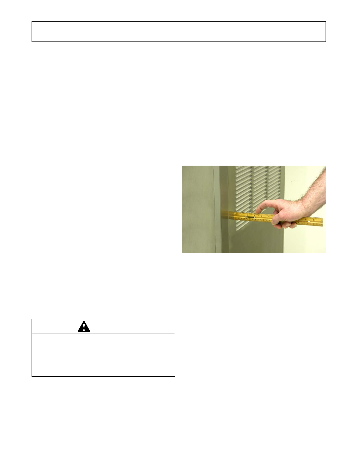
D. Machines with air cooled condensers require a
minimum of 3" (7,5cm) of space on all sides and
10" (25cm) at the top for proper circulation. (Fig. 2-
1)
Figure 2-1 Space and Ventilation Requirements
E. Machines that have a water cooled condenser
require 1/2" NPT supply and drain fittings.
2.4 INSTALLING PERMANENT WIRING
To install wiring follow the steps below:
A. Refer to the nameplate on the side panel of the
machine for specific electrical requirements. Make
sure the power source in the building matches the
nameplate requirements.
B. Remove the back panel and the junction box cover
located at the bottom of the machine.
C. Install permanent wiring according to local code.
Installation of the machine involves moving the machine
close to its permanent location, removing all crating,
setting in place, assembling parts, and cleaning.
3

4

SECTION 3
INITIAL SET-UP AND OPERATION
3.1 OPERATOR’S SAFETY PRECAUTIONS
SAFE OPERATION IS NO ACCIDENT; observe these
rules:
A. Know the machine. Read and understand the
Operating Instructions.
B. Notice all warning labels on the machine.
C. Wear proper clothing. Avoid loose fitting garments,
and remove watches, rings or jewelry that could
cause a serious accident.
D. Maintain a clean work area. Avoid accidents by
cleaning up the area and keeping it clean.
E. Stay alert at all times. Know which switch, push
button or control you are about to use and what
effect it is going to have.
F. Disconnect power for maintenance. Never attempt
to repair or perform maintenance on the machine
until the main electrical power has been
disconnected.
G. Do not operate under unsafe operating conditions.
Never operate the machine if unusual or excessive
noise or vibration occurs.
3.2 OPERATING CONTROLS AND
INDICATORS
Before operating the machine, it is required that the
operator know the function of each operating control. Refer
to Figure 3-1 for the location of the operating controls on the
machine. For the information regarding error codes displayed on the control panel, refer to the troubleshooting
section of this manual.
WARNING
High voltage will shock, burn or cause death. The
OFF-ON switch must be placed in the OFF position
prior to disassembling for cleaning or servicing. Do
not operate machine with panels removed.
Dispense Rate
Adjustor
Figure 3-1 Machine Controls
5
IntelliT ec2 Control
(See Figure 3-2)

A. INTELLITEC2 TOUCHPAD
Main Power On/Off
The Main Power button is used to supply power to the
IntelliTec2 control, the freezing cylinder circuits and the
storage refrigeration system. When the machine is first
plugged in, the control defaults to the On status with power
to the hopper only. If the Main Power On/Off button is
pressed when the machine is on, the machine will turn off
and a status message will be displayed on the screen.
Help
Pressing the Help button will display help information
dependant on the cursor's location. Pressing the Help
button again will exit the help screen.
Selection Button (SEL)
The SEL button is used to select menu options. For details
of the menu options, refer to Section 4.
Set Button (SET)
The SET button is used to save changes when modifying
control settings. Refer to Section 4 for details.
On/Off Button
Power to the freezing cylinders can then be controlled with
the On/Off Left and On/Off Right switches.
Push to Freeze Button
Pressing the PUSH TO FREEZE button initiates "Serve
Mode".
Clean Button
The CLEAN button initiates "Clean Mode".
Arrow Buttons (
The arrow buttons are used to navigate through the control
readings and settings. Section 2 contains details on all the
readings and settings.
B. SPIGOT SWITCH
The spigot switch is mounted to the spigot cam assembly
behind the header panel. When the spigot is opened to
dispense product, the spigot switch opens and the "Serve
Mode" begins.
C. DISPENSE RATE ADJUSTOR
The dispense rate adjustor is located under the header
panel, to the immediate right of the spigot handles. Turning the knob counterclockwise will decrease the dispense
rate.
⇐, ⇑, ⇒, ⇓⇐, ⇑, ⇒, ⇓
⇐, ⇑, ⇒, ⇓)
⇐, ⇑, ⇒, ⇓⇐, ⇑, ⇒, ⇓
3.3 IMPORTANT INFORMATION REGARDING
CLEANING AND SANITIZING
Soft serve machines require special consideration when it
comes to food safety and proper cleaning and sanitizing.
The following information specifically covers issues for
cleaning and sanitizing frozen dessert machines. This
information is meant to supplement a comprehensive food
safety program.
Figure 3-2 IntelliT ec2 Control
SOIL MATERIALS ASSOCIATED WITH FROZEN
DESSERT MACHINES
MILKFAT/BUTTERFAT – As components of ice-cream/
frozen custard mix, these soils will accumulate on the
interior surfaces of the machine and its parts. Fats are
difficult to remove and help attribute to milkstone buildup.
MILKSTONE – Is a white/gray film that forms on equipment and utensils that are exposed to dairy products.
These films will accumulate slowly on surfaces because of
ineffective cleaning, use of hard water, or both. Milkstone is
usually a porous deposit, which will harbor microbial
contaminants and eventually defy sanitizing efforts.
Once milkstone has formed, it is very difficult to remove.
Without using the correct product and procedure, it is
nearly impossible to remove a thick layer of milkstone.
(NOTE: general-purpose cleaners DO NOT remove
milkstone.) This can lead to high bacteria counts and a
food safety dilemma.
IT IS BEST TO CONTROL MILKSTONE ON A DAILY
BASIS BEFORE IT CAN BECOME A SIGNIFICANT FOOD
SAFETY PROBLEM.
In addition to food safety, milkstone can cause premature
wear to machine parts, which can add to costs for replacement parts or possibly more expensive repairs if worn
machine parts are not replaced once they have become
excessively worn.
IMPORTANT DIFFERENCES BETWEEN CLEANING AND
SANITIZING
CLEANING vs. SANITIZING
It is important to distinguish between cleaning and sanitiz-
ing. Although these terms may sound synonymous, they
are not. BOTH are required for adequate food safety and
proper machine maintenance.
6
 Loading...