

Stoelting O212B Service Manual

Model O212B
OPERATORS MANUAL
Manual No. 513705 Rev.0


This manual provides basic information about the machine. Instructions and suggestions are
given covering its operation and care.
The illustrations and specifi cations are not binding in detail. We reserve the right to make
changes to the machine without notice, and without incurring any obligation to modify or provide new parts for machines built prior to date of change.
DO NOT ATTEMPT to operate the machine until instructions and safety precautions in this
manual are read completely and are thoroughly understood. If problems develop or questions
arise in connection with installation, operation, or servicing of the machine, contact Stoelting.
stoeltingfoodservice.com
Stoelting Foodservice Equipment
502 Highway 67
Kiel, WI 53042-1600
U.S.A.
White Glove Service Network
Phone: 888.319.9549
© 2017 Stoelting

A Few Words About Safety
Safety Information
Read and understand the entire manual before
operating or maintaining Stoelting equipment.
This manual provides the operator with information
for the safe operation and maintenance of Stoelting
equipment. As with any machine, there are hazards
associated with their operation. For this reason safety
is emphasized throughout the manual. To highlight
specifi c safety information, the following safety defi ni-
tions are provided to assist the reader.
The purpose of safety symbols is to attract your attention to possible dangers. The safety symbols, and
their explanations, deserve your careful attention
and understanding. The safety warnings do not by
themselves eliminate any danger. The instructions
or warnings they give are not substitutes for proper
accident prevention measures.
If you need to replace a part, use genuine Stoelting
parts with the correct part number or an equivalent
part. We strongly recommend that you do not use
replacement parts of inferior quality.
Safety Alert Symbol:
This symbol Indicates danger, warning or caution.
Attention is required in order to avoid serious personal injury. The message that follows the symbol
contains important information about safety.
Signal Word:
Signal words are distinctive words used throughout
this manual that alert the reader to the existence and
relative degree of a hazard.
WARNING
The signal word “WARNING” indicates a potentially
hazardous situation, which, if not avoided, may result
in death or serious injury and equipment/property
damage.
CAUTION
The signal word “CAUTION” indicates a potentially
hazardous situation, which, if not avoided, may result
in minor or moderate injury and equipment/property
damage.
CAUTION
The signal word “CAUTION” not preceded by the
safety alert symbol indicates a potentially hazardous
situation, which, if not avoided, may result in equipment/property damage.
NOTE (or NOTICE)
The signal word “NOTICE” indicates information or
procedures that relate directly or indirectly to the
safety of personnel or equipment/property.

TABLE OF
CONTENTS
Section Description Page
1 Description and Specifi cations
1.1 Description ..................................................................................................1
1.2 Specifi cations .............................................................................................2
2 Installation Instructions
2.1 Safety Precautions .....................................................................................3
2.2 Shipment and Transit ..................................................................................3
2.3 Machine Installation ....................................................................................3
3 Initial Set-Up and Operation
3.1 Operator’s Safety Precautions ...................................................................5
3.2 Operating Controls and Indicators .............................................................5
3.3 Assembly of Machine .................................................................................6
3.4 Sanitizing ....................................................................................................7
3.5 Freeze Down and Operation ......................................................................8
3.6 Mix Information ...........................................................................................8
3.7 Removing Mix From Machine .....................................................................8
3.8 Cleaning the Machine .................................................................................8
3.9 Disassembly of Machine Parts ...................................................................8
3.10 Cleaning and Sanitizing The Machine Parts ...............................................9
3.11 Sanitize Machine ........................................................................................9
3.12 Routine Cleaning ........................................................................................9
3.13 Preventive Maintenance .............................................................................10
3.14 Extended Storage .......................................................................................10
4 Troubleshooting
4.1 Light Indicators ...........................................................................................11
4.2 Troubleshooting ..........................................................................................11
5 Replacement Parts
5.1 Brushes, Decals, and Lubrication ...............................................................13
5.2 Auger Shaft and Faceplate Parts ...............................................................14
5.3 Hopper Parts ..............................................................................................15

SECTION 1
DESCRIPTION AND SPECIFICATIONS
1.1 DESCRIPTION
The Stoelting O212B fl oor model machine is gravity fed.
The machine is equipped with fully automatic controls to
provide a uniform product. The machine will operate with
almost any type of shake mix. This manual is designed to
help qualifi ed service personnel and operators with the
installation, operation and maintenance of the Stoelting
O212B gravity machine.
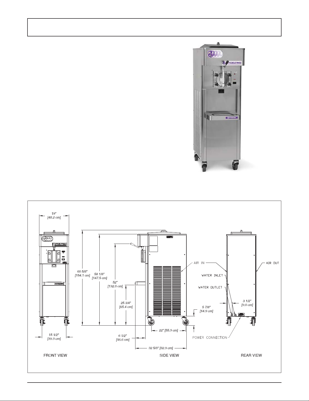
Figure 1-1 Model O212B
Operators Manual #513705 1 O212B Model Machines

1.2 SPECIFICATIONS
Model O212B
Dimensions Machine with crate
width 19’’ (48,3 cm) 25’’ (63,5 cm)
height 60-5/8’’ (154,0 cm) 66’’ (167,6 cm)
depth 32-5/8’’ (82,9 cm) 51’’ (129,5 cm)
Weight 315 lbs (142,8 kg) 500 lbs (226,7 kg)
Electrical 1 Phase, 208-240 VAC, 60Hz
running amps 11A
connection type NEMA6-20P power cord provided
Compressor 12,000 Btu/hr
Drive Motor 3/4 hp
Air Flow Air cooled units require 3” (7,6 cm) air space on both sides
Plumbing Fittings Water cooled units require 3/8” N.P.T. water and drain fi ttings
Hopper Volume 6.5 gallon (24,61 liters)
Freezing Cylinder
Volume
2 gallon (7,57 liters)
Operators Manual #513705 2 O212B Model Machines
 Loading...