

Stoelting O212 Service Manual

Model O212
OPERATORS MANUAL
Manual No. 513589 Rev.2


This manual provides basic information about the machine. Instructions and suggestions are
given covering its operation and care.
The illustrations and specifi cations are not binding in detail. We reserve the right to make
changes to the machine without notice, and without incurring any obligation to modify or provide new parts for machines built prior to date of change.
DO NOT ATTEMPT to operate the machine until instructions and safety precautions in this
manual are read completely and are thoroughly understood. If problems develop or questions
arise in connection with installation, operation, or servicing of the machine, contact Stoelting.
stoeltingfoodservice.com
Stoelting Foodservice Equipment
502 Highway 67
Kiel, WI 53042-1600
U.S.A.
Main Tel: 800.558.5807
Fax: 920.894.7029
Customer Service: 888.429.5920
Fax: 800.545.0662
Email: foodservice@stoelting.com
© 2014 PW Stoelting, LLC
A Few Words About Safety
Safety Information
Read and understand the entire manual before
operating or maintaining Stoelting equipment.
This manual provides the operator with information
for the safe operation and maintenance of Stoelting
equipment. As with any machine, there are hazards
associated with their operation. For this reason safety
is emphasized throughout the manual. To highlight
specifi c safety information, the following safety defi ni-
tions are provided to assist the reader.
The purpose of safety symbols is to attract your attention to possible dangers. The safety symbols, and
their explanations, deserve your careful attention
and understanding. The safety warnings do not by
themselves eliminate any danger. The instructions
or warnings they give are not substitutes for proper
accident prevention measures.
If you need to replace a part, use genuine Stoelting
parts with the correct part number or an equivalent
part. We strongly recommend that you do not use
replacement parts of inferior quality.
Safety Alert Symbol:
This symbol Indicates danger, warning or caution.
Attention is required in order to avoid serious personal injury. The message that follows the symbol
contains important information about safety.
Signal Word:
Signal words are distinctive words used throughout
this manual that alert the reader to the existence and
relative degree of a hazard.
WARNING
The signal word “WARNING” indicates a potentially
hazardous situation, which, if not avoided, may result
in death or serious injury and equipment/property
damage.
CAUTION
The signal word “CAUTION” indicates a potentially
hazardous situation, which, if not avoided, may result
in minor or moderate injury and equipment/property
damage.
CAUTION
The signal word “CAUTION” not preceded by the
safety alert symbol indicates a potentially hazardous
situation, which, if not avoided, may result in equipment/property damage.
NOTE (or NOTICE)
The signal word “NOTICE” indicates information or
procedures that relate directly or indirectly to the
safety of personnel or equipment/property.

TABLE OF CONTENTS
SECTION DESCRIPTION PAGE
1. INTRODUCTION
1.1 Description............................................................................................................. 1
1.2 Specifications ........................................................................................................ 1
2. INSTALLATION INSTRUCTIONS
2.1 Safety Precautions ................................................................................................. 3
2.2 Shipment and Transit.............................................................................................. 4
2.3 Freezer Installation ................................................................................................. 4
2.4 Installing Permanent Wiring .................................................................................... 5
3. INITIAL SET-UP AND OPERATION
3.1 Operator's Safety Precautions................................................................................ 7
3.2 Operating Controls and Indicators........................................................................... 7
3.3 Sanitizing ............................................................................................................... 8
3.4 Freeze Down and Operation................................................................................... 9
3.5 Mix Information ....................................................................................................... 10
3.6 Removing Mix From Freezer .................................................................................. 10
3.7 Cleaning The Freezer............................................................................................. 11
3.8 Disassembly of Freezer Parts ................................................................................ 11
3.9 Cleaning The Freezer Parts.................................................................................... 12
3.10 Sanitize Freezer and Freezer Parts....................................................................... 12
3.11 Assembly of Freezer ............................................................................................. 12
3.12 Routine Cleaning................................................................................................... 13
3.13 Preventive Maintenance ........................................................................................ 15
3.14 Extended Storage ................................................................................................. 16
4. TROUBLESHOOTING CHARTS................................................................................ 17
5. REFERENCE DRAWINGS ......................................................................................... 20
5.1 Auger and Front Door Drawings ............................................................................ 20
5.2 Air Cooled Parts & Wiring Diagram....................................................................... 22
5.3 Water Cooled Parts & Wiring Diagram.................................................................. 29
5.4 General Parts List.................................................................................................. 35

LIST OF ILLUSTRATIONS
FIGURE TITLE PAGE
1 Model Optima 212 Freezer .................................................................................... 1
2 Specifications ........................................................................................................ 1
3 Warning Label Locations ....................................................................................... 3
4 Leveling ................................................................................................................. 4
5 Space and Ventilation Requirements ..................................................................... 4
6 Electrical Plug ....................................................................................................... 4
7 Installing Tray and Cover ........................................................................................ 4
8 Power Cord Connection ......................................................................................... 5
9 Controls ................................................................................................................. 7
10 Mix Inlet Regulator ................................................................................................. 9
11 Clean Control ......................................................................................................... 9
12 Sanitizing Hopper .................................................................................................. 9
13 Draining Solution ................................................................................................... 9
14 Dispensing Product ...............................................................................................10
15 Removing Mix Inlet Regulator.................................................................................10
16 Draining Mix ..........................................................................................................11
17 Removing Front Door .............................................................................................11
18 Auger Shaft Removal .............................................................................................12
19 Removing "O" Ring ................................................................................................12
20 Cleaning Freezer Barrel .........................................................................................12
21 Exploded View of Auger.........................................................................................13
22 Mix Inlet Regulator .................................................................................................13
SECTION 1
DESCRIPTION AND SPECIFICATIONS
1.1 DESCRIPTION
The Stoelting Optima 212 floor model freezer is gravity
fed. The freezer is equipped with fully automatic controls
to provide a uniform product. The freezer is designed to
operate with almost any type of commercial shake mix
available. This manual is designed to assist qualified service personnel and operators in the installation, operation
and maintenance of the Stoelting Model Optima 212
freezer.
1.2 SPECIFICATIONS
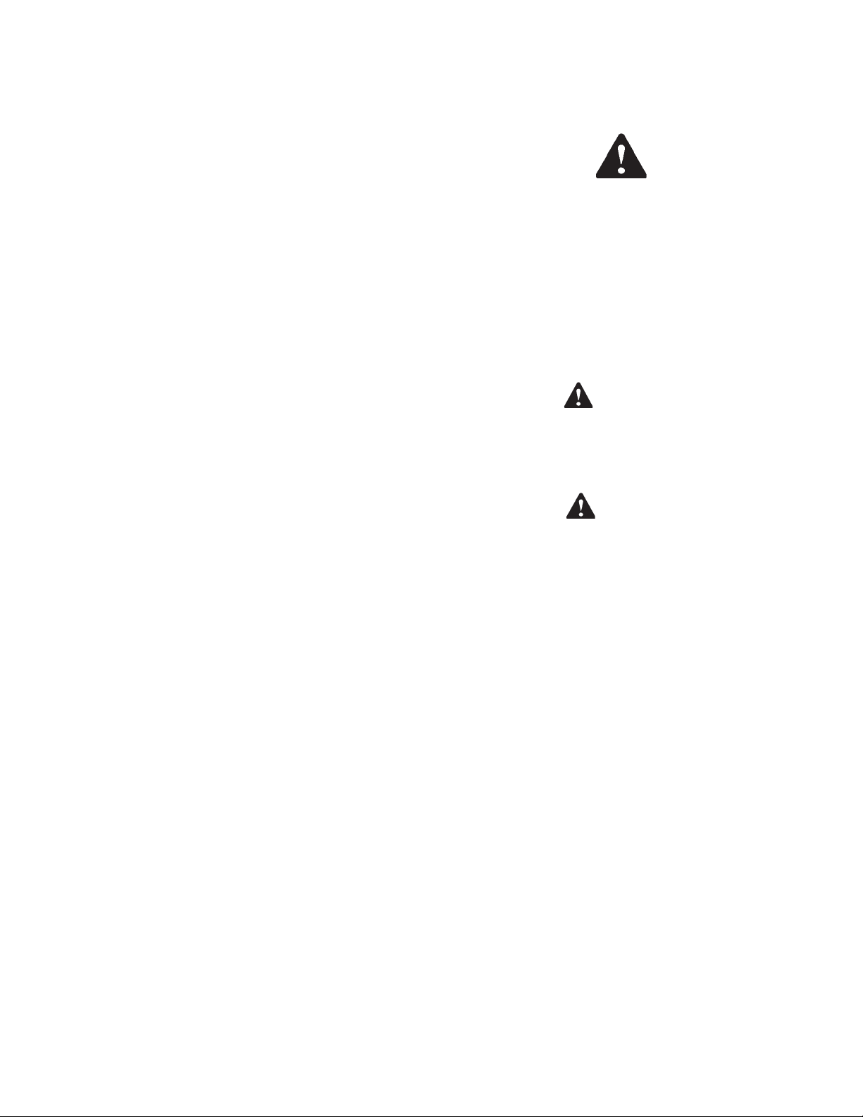
Figure 1. Model Optima 212 Freezer
/,67('5 <6&
Figure 2. Specifications
1

MODEL OPTIMA 212
FLOOR MODEL
GRA VITY SHAKE FREEZER
DIMENSIONS:
Freezer: 17.6" (45cm) wide x 28.6" (73cm) deep x 63.75" (162cm) high
Crated: 19.5" (50cm) wide x 33" (84cm) deep x 40" (102cm) high
WEIGHT:
Freezer: 332 lbs. (150kg) Cra ted : 427 lbs. (193kg)
ELECTRICAL:
Description Optima 212-38
Voltage AC 1 PH 208/230
Total Run Amp s 10.5
Drive Motor 3/4 HP
Compressor 10,760 BTUH (90°F - 0°F)
Use 20 amp HACR circuit breaker .
Automatic safeguard circuit built into electronic control - protects major
freezer components under abnormal operating conditions.
COOLING:
Air cooled requires minimum 3" (7.6cm) air clearance on back side.
No clearance needed on sides.
HOPPER:
6.25 Gallons (23.7 liters) refrigerated and insulated.
2

SECTION 2
INSTALLATION INSTRUCTIONS
2.1 SAFETY PRECAUTIONS
Do not attempt to operate the freezer until the safety
precautions and operating instructions in this manual are
read completely and are thoroughly understood.
Take notice of all warning labels on the freezer. The labels
have been put there to help maintain a safe working
environment. The labels have been designed to withstand
washing and cleaning. All labels must remain legible for
the life of the freezer. Labels should be checked periodically to be sure they can be recognized as warning labels.
If danger, warning or caution labels are needed, indicate
the part number, type of label, location of label, and
quantity required along with your address and mail to:
STOELTING, INC.
ATTENTION: Customer Service
502 Hwy. 67
Kiel, Wisconsin 53042
Figure 3. Warning Label Locations
3
2.2 SHIPMENT AND TRANSIT
The freezer has been assembled, operated and inspected
at the factory. Upon arrival at the final destination, the
complete freezer must be checked for any damage which
may have occurred during transit.
With the method of packaging used, the freezer should
arrive in excellent condition. THE CARRIER IS RESPONSIBLE FOR ALL DAMAGE IN TRANSIT, WHETHER
VISIBLE OR CONCEALED. Do not pay the freight bill until
the freezer has been checked for damage. Have the carrier
note any visible damage on the freight bill. If concealed
damage and/or shortage is found later, advise the carrier
within 10 days and request inspection. The customer must
place claim for damages and/or shortages in shipment
with the carrier. Stoelting, Inc. cannot make any claims
against the carrier.
2.3 FREEZER INSTALLATION
Installation of the freezer involves moving the freezer close
to its permanent location, removing all crating, setting in
place, assembling parts, and cleaning.
A. Uncrate the freezer.
Figure 5. Space and Ventilation Requirements
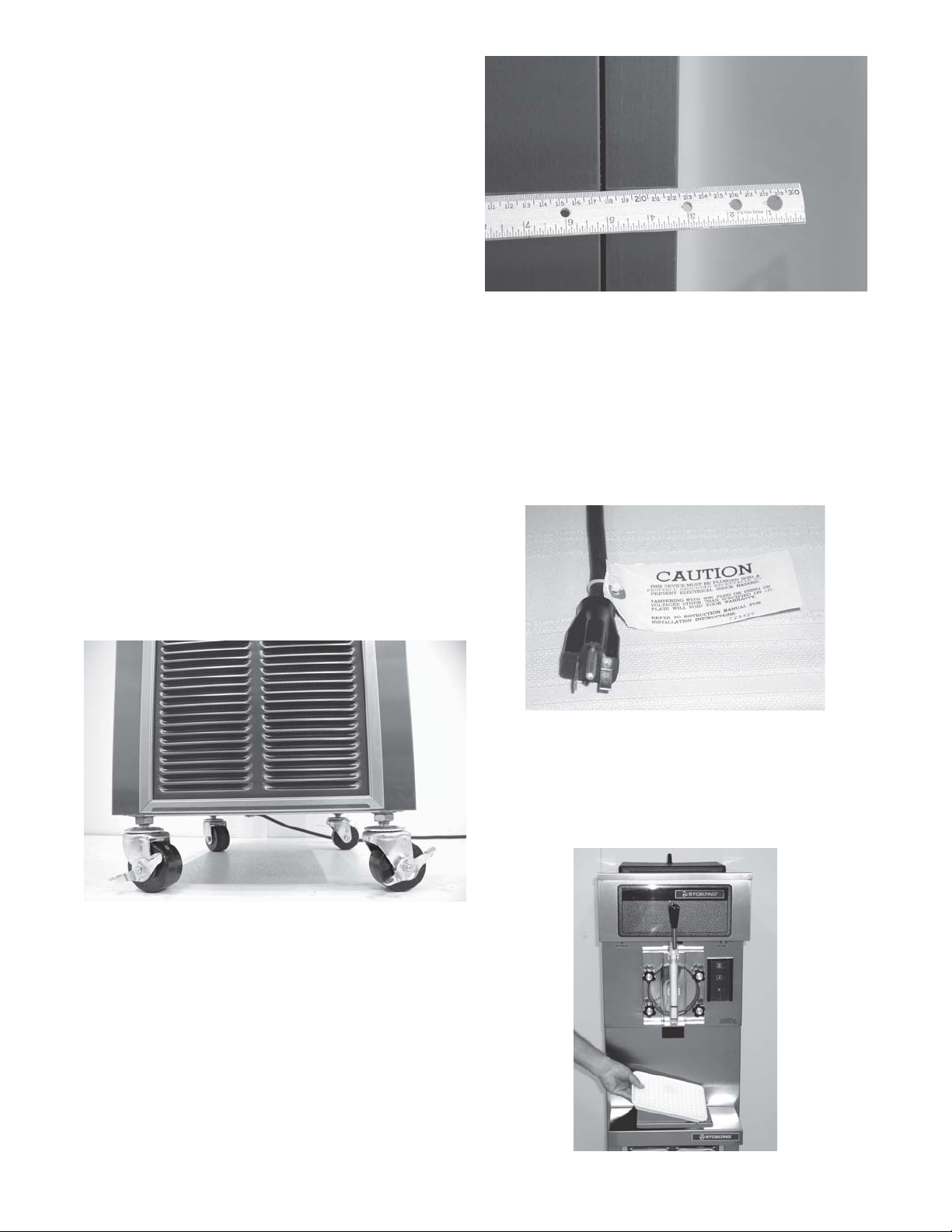
E. Connect the power cord. The plug is designed for 208
or 230 volt/20 amp duty. Check the nameplate on your
freezer for proper supply. The unit must be connected
to a properly grounded receptacle. The electrical cord
furnished as part of the freezer has a three prong
grounding type plug (Fig. 6). The use of an extension
cord is not recommended, if necessary use one with
a size 12 gauge or heavier with ground wire. Do not use
an adapter to get around grounding requirement.
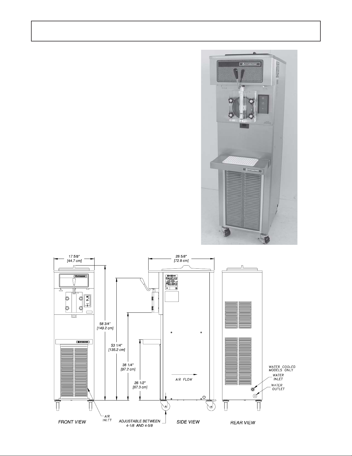
B. Accurate leveling is necessary for correct drainage
of freezer barrel and to insure correct overrun. Place
a spirit level on top of the freezer at each corner to
check for level condition. If adjustment is necessary,
level the freezer by turning the caster in or out and
tighten the locknut. (Fig. 4).
Figure 4. Leveling
Figure 6. Electrical Plug
CAUTION
DO NOT ALTER OR DEFORM PLUG IN ANY WAY!
F. Install the drip tray, drain tray, hopper cover and other
miscellaneous parts on the freezer. (Fig. 7).
C. The freezer is equipped with an air cooled condenser
and requires correct ventilation. The front of the
freezer is the air intake and the back discharge. Both
front and back must have a minimum of 3" of
clearance. (Fig. 5).
CAUTION
FAILURE T O PROVIDE ADEQUA TE VENTILA TION
WILL VOID WARRANTY!
D. Place the OFF-ON switch in the OFF position. (Fig.10).
Figure 7. Installing Tray and Cover
4
 Loading...