

Page 1

Model F231
SERVICE MANUAL
Manual No. 513659 Rev.2
Page 2

Page 3

This manual provides basic information about the machine. Instructions and suggestions are
given covering its operation and care.
The illustrations and specifi cations are not binding in detail. We reserve the right to make
changes to the machine without notice, and without incurring any obligation to modify or provide new parts for machines built prior to date of change.
DO NOT ATTEMPT to operate the machine until instructions and safety precautions in this
manual are read completely and are thoroughly understood. If problems develop or questions
arise in connection with installation, operation, or servicing of the machine, contact Stoelting.
stoeltingfoodservice.com
Stoelting Foodservice Equipment
502 Highway 67
Kiel, WI 53042-1600
U.S.A.
Main Tel: 800.558.5807
Fax: 920.894.7029
Customer Service: 888.429.5920
Fax: 800.545.0662
Email: foodservice@stoelting.com
© 2014 PW Stoelting, LLC
Page 4

A Few Words About Safety
Safety Information
Read and understand the entire manual before
operating or maintaining Stoelting equipment.
This manual provides the operator with information
for the safe operation and maintenance of Stoelting
equipment. As with any machine, there are hazards
associated with their operation. For this reason safety
is emphasized throughout the manual. To highlight
specifi c safety information, the following safety defi ni-
tions are provided to assist the reader.
The purpose of safety symbols is to attract your attention to possible dangers. The safety symbols, and
their explanations, deserve your careful attention
and understanding. The safety warnings do not by
themselves eliminate any danger. The instructions
or warnings they give are not substitutes for proper
accident prevention measures.
If you need to replace a part, use genuine Stoelting
parts with the correct part number or an equivalent
part. We strongly recommend that you do not use
replacement parts of inferior quality.
Safety Alert Symbol:
This symbol Indicates danger, warning or caution.
Attention is required in order to avoid serious personal injury. The message that follows the symbol
contains important information about safety.
Signal Word:
Signal words are distinctive words used throughout
this manual that alert the reader to the existence and
relative degree of a hazard.
WARNING
The signal word “WARNING” indicates a potentially
hazardous situation, which, if not avoided, may result
in death or serious injury and equipment/property
damage.
CAUTION
The signal word “CAUTION” indicates a potentially
hazardous situation, which, if not avoided, may result
in minor or moderate injury and equipment/property
damage.
CAUTION
The signal word “CAUTION” not preceded by the
safety alert symbol indicates a potentially hazardous
situation, which, if not avoided, may result in equipment/property damage.
NOTE (or NOTICE)
The signal word “NOTICE” indicates information or
procedures that relate directly or indirectly to the
safety of personnel or equipment/property.
Page 5

INTELLITEC2™ FIRMWARE
VERSION UPDATE LOG
The list below shows the history of the fi rmware versions in the IntelliTec2™ control. The information in this manual
refers to Version 20.39.
VERSION 20.52
Released on 8/22/11
• Motor Calibration screen now returns to the current status screen after pressing the left arrow.
• Refer Solenoid text changed to Storage Refrigeration.
• When exporting the error log data the fi le name is now the serial number of machine.
• Serial Number can now be changed in the Modify Contact Information screen.
• CutIn Offset changed to 20 (was 30)
• Default Offtime changed to 450 (was 300)
VERSION 20.39
Released on 3/2/11
• Added phase reversal detection for 3 phase machines
• Added Spigot Open Time error Error 21
• Added support for I/O update
• Changed High Torque Error 2 detection to be directly from motor amperage and not from a calculated factor
VERSION 20.27
Released on 12/28/10
• Added Unit Serial Number to Service Contact Information and Modify Contact Information
• Added Clean Warning to Clean Options
VERSION 20.15
Released 11/23/10
• Added Enable Control to Basic Settings
• Removed Enable CutOut Temp from Basic Settings
• Changed CutOut Consistency to CutOut Consistency Offset
• Added CutIn Consistency Offset
• Moved Sleep 1 Drive On and Sleep 1 Drive Off to Factory Settings from Advanced Settings
• Moved Stir On and Stir Off to Advanced Settings from Factory Settings
• Added Storage Refrigeration to Storage Settings
• Storage CutIn changed to 37.5°F (was 37°F)
• Moved Pressure Sensing and Liquid Sensing to Factory Settings
• Added Clean Options to Utilities page 1
• Moved Clean Lockout to Clean Options from Utilities page 1
• Added Clean History Log to Clean Options
Service Manual #513659 iii Model F231
Page 6

VERSION 17.19
Released on 9/8/10
Note: They are few initial machines with 15.19 (8/23/10) where cutout consistency was 70, then pulleys were
changed. T wo machines with 16.19 had 60 as cutout limit, then some minor internal reset timers were changed
and 17.19 released on 9/8/10
• Consistency Limit changed to 60 (was 110 for 1 phase / 80 for 3 phase)
• Moved Stir On and Stir Off to Factory Settings from Basic Settings
• Enable CutOut Temp and CutOut Temp moved to Basic Settings from Factory Settings
• Sleep 1 Drive Off changed to 600 seconds (was 300 seconds)
• Sleep 2 CutIn changed to 33°F (was 38°F)
• Sleep 2 CutOut changed to 30.5°F (was 30°F)
(continued on next page)
VERSION 17.19 (CONTINUED)
• Storage CutOut changed to 32°F (was 31°F)
• Storage Offset changed to 4°F (was 2°F)
• Storage Off Time changed to 13 min (was 2 min)
• Storage On Time changed to 130 sec (was 200 sec)
• Storage Max On changed to 3 min (was 10 min)
• Storage Recovery changed to 4 min (was 1 min)
• Clean Lockout Period moved to Factory Settings from Storage Settings
• Touchpad Lockup moved to Utilities from User Preferences
• Date Format added to Time and Date
• Added second Utilities page
• Changed Utilities page 1 to be accessible to Manager passcode
• Testing and Manual Operation, Restore Factory Defaults, Clear Error Log and Clear Statistics moved to
Utilities page 2 from page 1
• Added Product Selection, Export Machine Stats to Utilities page 1
• Removed Clear EEPROM Map from Utilities
• Added Motor Zero Load Calibration, Restore Motor Table Defaults and Reset Unit Confi guration to Utilities
page 2
Service Manual #513659 iv Model F231
Page 7

TABLE OF
CONTENTS
Section Description Page
1 Description and Specifi cations
1.1 Description .................................................................................................. 1
1.2 Specifi cations ............................................................................................. 2
2 Installation Instructions
2.1 Safety Precautions ..................................................................................... 5
2.2 Shipment and Transit .................................................................................. 5
2.3 Machine Installation .................................................................................... 5
2.4 Installing Permanent Wiring ........................................................................ 5
2.5 Initial Startup of IntelliTec2™ ......................................................................6
3 Initial Set-Up and Operation
3.1 Operator’s Safety Precautions .................................................................... 9
3.2 Operating Controls and Indicators .............................................................. 9
3.3 Disassembly of Machine Parts ................................................................... 10
3.4 Cleaning Disassembled Parts ....................................................................11
3.5 Sanitizing Machine Parts ............................................................................11
3.6 Cleaning the Machine ................................................................................. 11
3.7 Assembling the Machine ............................................................................12
3.8 Sanitizing ....................................................................................................12
3.9 Freeze Down and Operation ......................................................................13
3.10 Fine Consistency Adjustment ..................................................................... 13
3.11 Mix Information ........................................................................................... 14
4 Maintenance and Adjustments
4.1 Accessing Control Readings and Settings .................................................15
4.2 Navigation and Modifying Settings ............................................................. 15
4.3 User Interface Screens ............................................................................... 15
4.4 Performance Screens ................................................................................. 16
4.5 Settings Screens ........................................................................................ 16
4.6 Utilities Screens .......................................................................................... 18
4.7 Errors & Statistics Screens ......................................................................... 21
4.8 Updating Firmware .....................................................................................23
4.9 Drive Belt Tension Adjustment ....................................................................24
4.10 Condenser Cleaning ................................................................................... 25
4.11 Preventative Maintenance .......................................................................... 25
4.12 Extended Storage ....................................................................................... 25
Page 8

Section Description Page
5 Refrigeration System
5.1 Refrigeration System .................................................................................. 27
5.2 Refrigerant Recovery and Evacuation ........................................................ 27
5.3 Refrigerant Charging ..................................................................................28
5.4 Compressor ................................................................................................29
5.5 Condenser ..................................................................................................30
5.6 Valves ......................................................................................................... 30
A. Thermostatic Expansion Valve (TXV) ..................................................................30
B. Automatic Expansion Valve (AXV) .......................................................................31
C. Check Valve .........................................................................................................32
D. High Pressure Cutout ........................................................................................... 32
E. Hot Gas Bypass ...................................................................................................32
F. Evaporator Pressure Regulator (EPR) .................................................................33
G. Water Valve (Water Cooled Models Only) ............................................................ 34
5.7 Solenoid ...................................................................................................... 34
5.8 Filter Drier ................................................................................................... 36
5.9 Capillary Tube .............................................................................................36
6 Electrical and Mechanical Control Systems
6.1 IntelliTec2™ Control ................................................................................... 37
6.2 Contactors .................................................................................................. 37
6.3 Drive Motor .................................................................................................38
6.4 Capacitors .................................................................................................. 39
6.5 Gearbox ...................................................................................................... 39
6.6 Condenser Fan Motor (Air-Cooled Only) .................................................... 39
6.7 Spigot Switch .............................................................................................. 40
6.8 Temperature Control Sensor ......................................................................41
7 Troubleshooting
7.1 Error Codes ................................................................................................ 43
7.2 Troubleshooting .......................................................................................... 44
7.3 Troubleshooting - Machine .........................................................................46
8 Replacement Parts
8.1 Decals and Lubrication ...............................................................................47
8.2 Panels and Screws ..................................................................................... 47
8.3 Auger Shaft and Faceplate Parts ...............................................................48
8.4 Air Plenum Kit ............................................................................................. 49
8.5 Internal Components .................................................................................. 50
8.6 Spigot Assembly ......................................................................................... 52
8.7 Front ........................................................................................................... 52
8.8 Wiring Diagrams ......................................................................................... 53
Page 9

SECTION 1
INTRODUCTION
1.1 DESCRIPTION
The Stoelting F231 fl oor machine is gravity fed. The
machine is equipped with the IntelliTec2™ control which
provides a uniform product. The F231 is designed to
operate with almost any type of commercial soft serve or
non-dairy mixes available, including: ice milk, ice cream,
yogurt, and frozen dietary desserts.
This manual is designed to assist qualifi ed service per-
sonnel and operators in the installation, operation and
maintenance of the Stoelting F231 gravity machine.
Figure 1-1 Model F231
Service Manual #513659 1 Model F231
Page 10

1.2 SPECIFICATIONS
Figure 1-2 Dimension Specifi cations (variations on spigot handles and casters available)
Model F231
Dimensions Machine as shipped
width 19-1/4’’ (48,9 cm) 32’’ (81,3 cm)
height 58-1/4’’ (148,0 cm) 60’’ (152,4 cm)
depth 28’’ (71,1 cm) 39’’ (99,1 cm)
Weight 400 lbs (181,4 kg) 470 lbs (213,1 kg)
Electrical 1 Phase, 208-240 VAC, 60Hz 3 Phase, 208-240 VAC, 60Hz
running amps 12A 10A
connection type NEMA 6-20P power cord provided NEMA L15-20P power cord provided
International Option 1 Phase, 220-240 VAC, 50Hz
Compressor 12,000 Btu/hr (R-404A)
Drive Motor Two - 3/4 hp
Air Flow Air cooled units require 3” (7,6 cm) air space on both sides
Water cooled units require 1/2” N.P.T. water and drain fi ttings.
Plumbing Fittings
Maximum water pressure of 130 psi. Minimum water fl ow rate of 3 GPM. Ideal
EWT of 50°-70°F
Hopper Volume Two - 3 gallon (11,35 liters)
Freezing Cylinder
Volume
Service Manual #513659 2 Model F231
Two - 0.85 gallon (3,22 liters)
Page 11

Menu Display F231
Basic Enable Control Consistency/Consistency
CutOut Consist Offset 7
CutIn Consist Offset 20
CutIn Temp 19.5 °F
CutOut Temperature 19 °F
Cycles In Serve Mode 20
Advanced Standby On Time 10 sec
Standby Off Time 360 sec
Standby Time 120 min
Stir On 15 sec
Stir Off 600 sec
Sleep 2 CutIn 33 °F
Sleep 2 CutOut 30.5 °F
Default Off Time 300 sec
Storage Storage Refrigeration Active
Storage CutIn 37.5 °F
Storage CutOut 32 °F
Storage Offset 4 °F
Storage Off Time 13 min
Storage On Time 130 sec
Storage Max On 3 min
Storage Recovery 4 min
Storage Too Warm 50 °F
Storage Too Warm 2 hr
F231
Refrigerant R-404A
Charge
Suction Pressure
(at 72°F)
Discharge Pressure 225-235 psig
Hot Gas Bypass
Pressure
EPR Valve 68-70 psig
Service Manual #513659 3 Model F231
One Cylinder 18-22 psig
Both Cylinders 22-27 psig
14 psig (only hopper running)
(W/C) 32 oz
(A/C) 42 oz
Hopper Only 14 psig
Page 12
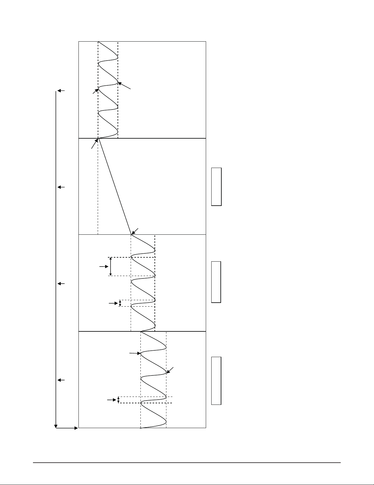
Sleep 2 CutIn
y
Sleep 2 Cutout
PUSH TO FREEZE or Spigot Pull
PUSH TO FREEZE or Spigot Pull
IntelliTec2™ Control Modes of Operation
Sleep 2 CutIn
Standby
Off Time
Standby Mode Sleep 1 Mode Serve Mode / Serve 2 Mode** Sleep 2 Mode
Standby
On Time
Standby
Time
Time* Sleep 2 CutIn*
or
PUSH TO FREEZE or Spigot Pull
CutIn
Consistency
Temperature
Freezing Cycle
CutOut
Consistency
Cycles Until Sleep* Standb
* Resets any time the PUSH TO FREEZE button is pressed or a spigot is pulled. In order for the mode to change, it has to go through its normal
the freezer will start up in the Serve mode.
1) A stir cycle will start in each mode. The cycle is independent of the freezing cycle.
2) Normal start up mode is Sleep 1 when the number of cycles is set below 99. When cycles are set higher than 99,
3) Sensor failure will keep the control in Serve and Standby modes only.
cycles without reset.
** After the Cycles Until Sleep number is met, Serve 2 Mode goes directly into Sleep 2 Mode.
Note:
active for the Consistency/Consistency setting and monitors CutIn Consistency. Both use CutOut Consistency.
4) A freeze cycle will reset the stir cycle.
5) Serve Mode is active for the Temperature/Consistency setting and monitors CutIn Temperature. Serve 2 Mode is
Temperature
Service Manual #513659 4 Model F231
Page 13
SECTION 2
INSTALLATION INSTRUCTIONS
2.1 SAFETY PRECAUTIONS
Do not attempt to operate the machine until the safety
precautions and operating instructions in this manual are
read completely and are thoroughly understood.
Take notice of all warning labels on the machine. The labels have been put there to help maintain a safe working
environment. The labels have been designed to withstand
washing and cleaning. All labels must remain legible for
the life of the machine. Labels should be checked periodically to be sure they can be recognized as warning labels.
If danger, warning or caution labels are needed, indicate
the part number, type of label, location of label, and quantity
required along with your address and mail to:
STOELTING
ATTENTION: Customer Service
502 Hwy. 67
Kiel, Wisconsin 53042
2.2 SHIPMENT AND TRANSIT
The machine has been assembled, operated and inspected
at the factory. Upon arrival at the fi nal destination, the
entire machine must be checked for any damage which
may have occurred during transit.
With the method of packaging used, the machine should
arrive in excellent condition. THE CARRIER IS RESPONSIBLE FOR ALL DAMAGE IN TRANSIT, WHETHER
VISIBLE OR CONCEALED. Do not pay the freight bill
until the machine has been checked for damage. Have
the carrier note any visible damage on the freight bill. If
concealed damage and/or shortage is found later, advise
the carrier within 10 days and request inspection. The
customer must place claim for damages and/or shortages
in shipment with the carrier. Stoelting, Inc. cannot make
any claims against the carrier.
2.3 MACHINE INSTALLATION
WARNING
Installation must be completed by a qualifi ed
electrician/refrigeration specialist.
Incorrect installation may cause personal injury,
severe damage to the machine and will void factory warranty.
A. Uncrate the machine.
B. Install the four casters. Turn the threaded end
into the machine until no threads are showing. To
level, turn out casters no more than 1/4” maximum,
then tighten all jam nuts.
C. The machine must be placed in a solid level
position.
NOTE
Accurate leveling is necessary for correct drainage
of freezing cylinder and to insure correct overrun.
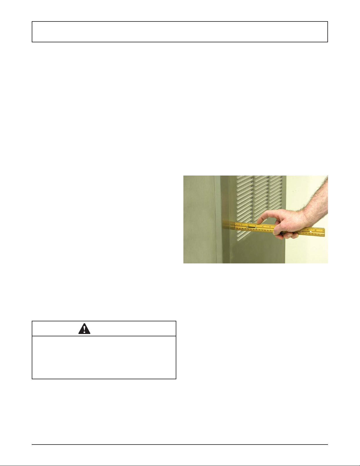
D. Machines with air cooled condensers require a
minimum of 3” (7,5cm) of space on both sides
for proper circulation. (Fig. 2-1)
E. Machines that have a water cooled condenser
require 1/2” NPT supply and drain fi ttings.
Figure 2-1 Space and Ventilation Requirements
2.4 INSTALLING PERMANENT WIRING
To install wiring follow the steps below:
A. Refer to the nameplate on the side panel of the
machine for specifi c electrical requirements. Make
sure the power source in the building matches
the nameplate requirements.
B. Remove the back panel and the junction box
cover located at the bottom of the machine.
C. Install permanent wiring according to local code.
Installation of the machine involves moving the machine
close to its permanent location, removing all crating, setting in place, assembling parts, and cleaning.
Service Manual #513659 5 Model F231
Page 14
2.5 INITIAL STARTUP OF INTELLITEC2™
Before completing the following procedures, follow the
steps in Section 3 to disassemble, clean, lubricate and
sanitize the machine.
NOTE
IntelliT ec2™ startup must be completed by a trained
authorized service provider or Stoelting distributor.
A. Locate a copy of the latest fi rmware fi le (uezimage.
rom) and service contact fi le (info.txt).
B. Modify the info.txt fi le with information from the
service company using the instructions in the fi le.
C. Put the fi rmware fi le and service contact fi le onto
the root level of a USB fl ash drive (do not put the
fi les into any folder).
D. Insert the fl ash drive into the USB port of the
machine.
E. Fill the mix containers in the cabinet with mix.
F. Connect power to the machine and press the
Main Power On/Off button and the Pump On/Off
buttons.
SETTING CONTACT INFORMATION
A. When the Current Status screen is displayed,
press the left arrow button to access the passcode
selection screen. Press the right arrow, SET, then
the SEL button.
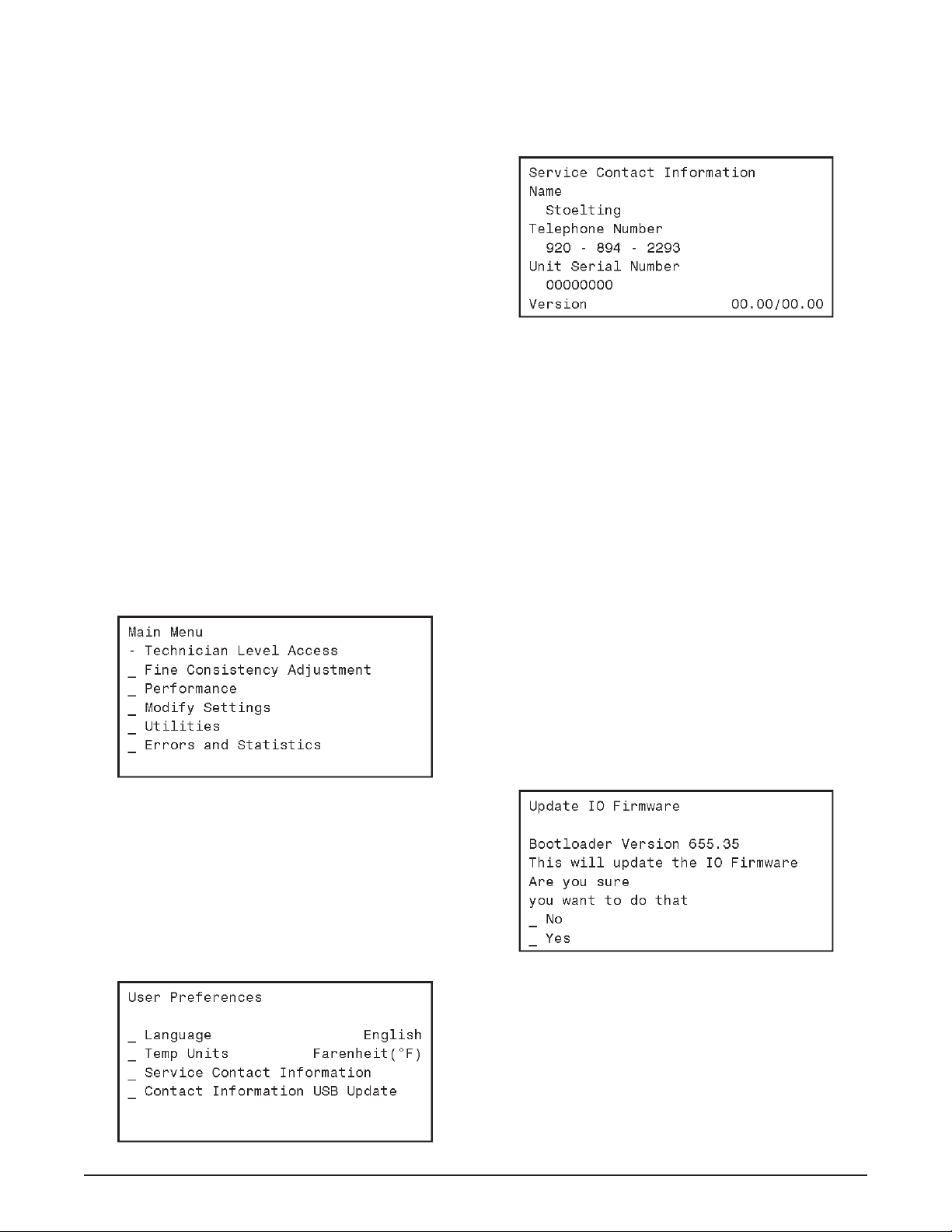
D. The screen will change and show “File Found” for
a quick second while it updates the information.
E. After updating the contact information, the screen
will show the Service Contact Information page.
Figure 2-4
F. Press the left arrow button to go back to the Current
Status screen. Then press the right arrow to go
to the Main Menu.
NOTE
If you press the left arrow from the Current Status
screen it will ask for the password. Press the right
arrow, SET, then the SEL button.
UPDATING FIRMWARE
If the control has the latest fi rmware, skip this section and
go to the Motor Calibration section.
A. Move the cursor to the Utilities option and press
the SEL button. Then move the cursor to the Next
Utilities Menu and press the SEL button.
B. On the Utilities (2 of 2) screen move the cursor
to the Update IO Firmware option and press the
SEL button.
C. On the Update IO Firmware screen select the
Yes option.
Figure 2-2
B. After the password is accepted, use the arrows to
move the cursor to the Modify Settings option and
press the SEL button. Then move the cursor to
the User Preferences and press the SEL button.
C. On the User Preferences screen move the cursor
to the Contact Information USB Update and press
the SEL button.
D. This process will take about 4 minutes. DO NOT
INTERRUPT this upload. The control will go
through several process steps and return to the
Main Menu when the update is completed.
Figure 2-3
Service Manual #513659 6 Model F231
Figure 2-5
Page 15
E. Press the left arrow button to go back to the Current
Status screen. Then press the right arrow to go
to the Main Menu.
NOTE
If you press the left arrow from the Current Status
screen it will ask for the password. Press the right
arrow, SET, then the SEL button.
MOTOR CALIBRATION
Before starting the motor calibration, be sure there is liquid
mix in the freezing cylinder.
A. Select the Utilities option, then the Next Utilities
option. Select the Unit Calibration then the Motor
Calibration option.
B. Move the cursor over the Left side and press the
SEL button then move the cursor over the Right
side and press the SEL button.
Figure 2-6
NOTE
The motor calibration can be done for both sides
simultaneously.
C. After the calibration is complete, press the Main
Power On/Off button to turn the machine off and
remove the USB fl ash drive.
SETTING CONTROL
A. Press the Main Power On/Off button.
B. When the Current Status screen is displayed,
press the left arrow button to access the passcode
selection screen. Press the right arrow, SET, then
the SEL button.
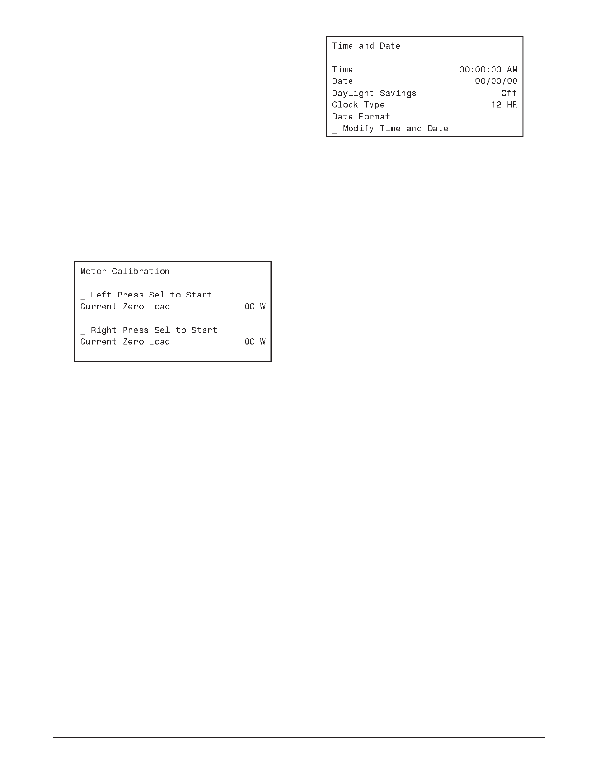
C. Move the cursor to the Modify Settings option
and press the SEL button. Then move the cursor
to the Time and Date option and press the SEL
button and adjust the settings as required.
1. Press the SEL button to enter the Modify Time
and Date screen.
2. Move the cursor to the setting that needs to
be changed and press the SET button.
3. Use the arrow buttons to change the setting
and press the SET button to save the change.
Figure 2-7
D. Press the Push to Freeze button and let the
machine cycle 4-5 times.
E. Draw product from the barrel immediately after
the compressor cycles off after the fi fth time and
test the product for consistency and temperature.
F. Adjust the product consistency by increasing or
decreasing the CutIn Consist Offset setting.
G. If the machine short cycles (short on/off
compressor run times), change the settings as
follows:
1. If the product is too soft, increase the CutOut
Consist Offset.
2. If the product is too fi rm, decrease the CutIn
Consist Offset.
H. Allow the machine to cycle 3-4 more times after
making the adjustment.
I. After 3-4 cycles, draw product from the barrel
immediately after the compressor cycles on.
If the product is servable when the compressor
cycles on but it is too fi rm at the end of the cycle,
reduce the CutOut Consist Offset.
SETTING DISCHARGE PRESSURE ON WATER
COOLED MACHINES
A. Water cooled machines require the water
condenser valves to be adjusted to maintain
a discharge pressure of 225-235 psig. When
adjusting the discharge pressure the machine
must be under a full load with both cylinders
running and the hopper running (if applicable).
Service Manual #513659 7 Model F231
Page 16

Service Manual #513659 8 Model F231
Page 17
SECTION 3
INITIAL SET-UP AND OPERATION
3.1 OPERATOR’S SAFETY PRECAUTIONS
SAFE OPERATION IS NO ACCIDENT; observe these
rules:
A. Know the machine. Read and understand the
Operating Instructions.
B. Notice all warning labels on the machine.
C. Wear proper clothing. Avoid loose fi tting garments,
and remove watches, rings or jewelry that could
cause a serious accident.
D. Maintain a clean work area. Avoid accidents by
cleaning up the area and keeping it clean.
E. Stay alert at all times. Know which switch, push
button or control you are about to use and what
effect it is going to have.
F. Disconnect power for maintenance. Never
attempt to repair or perform maintenance on the
machine until the main electrical power has been
disconnected.
G. Do not operate under unsafe operating conditions.
Never operate the machine if unusual or excessive
noise or vibration occurs.
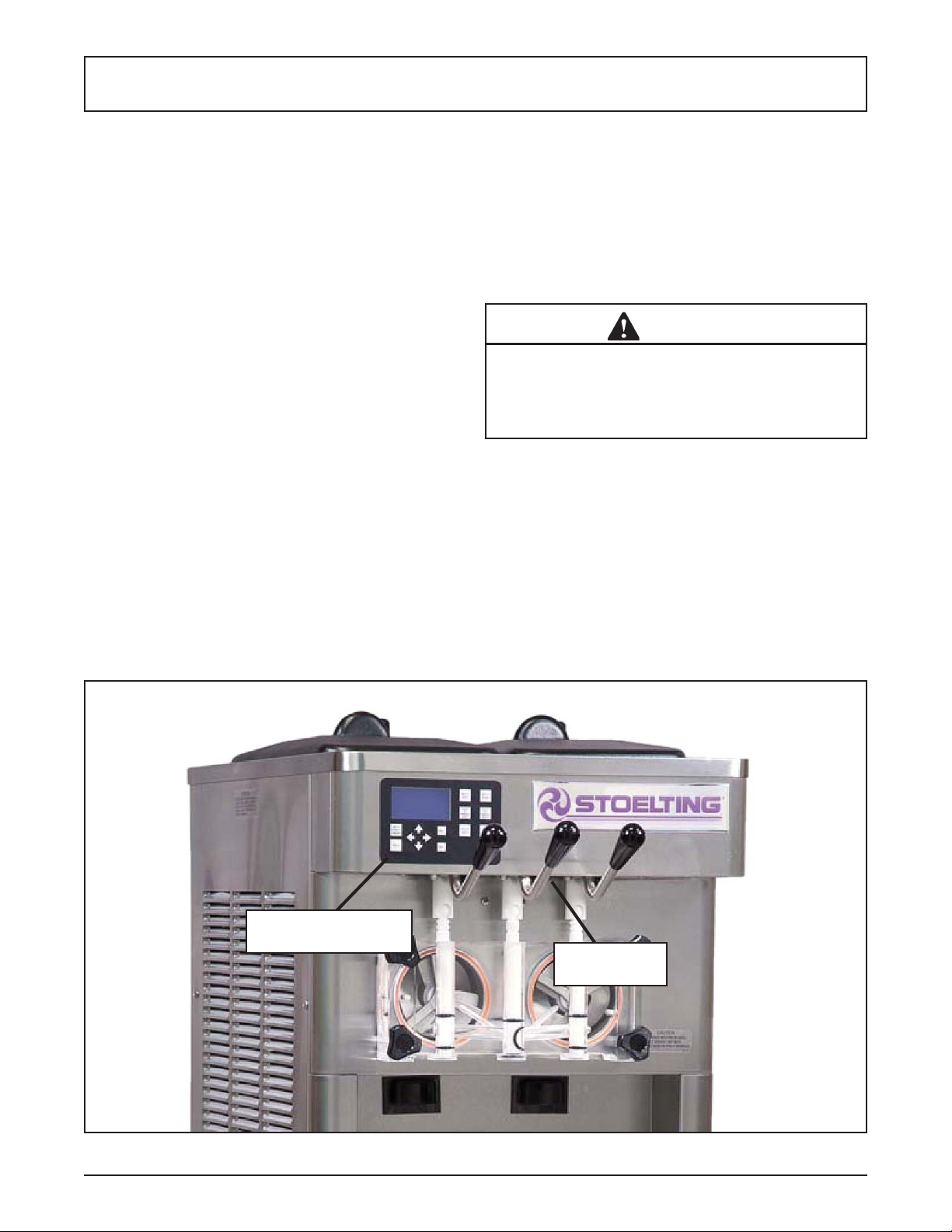
3.2 OPERATING CONTROLS AND INDICATORS
Before operating the machine, it is required that the operator know the function of each operating control. Refer
to Figure 3-1 for the location of the operating controls on
the machine. For the information regarding error codes
displayed on the control panel, refer to the troubleshooting
section of this manual.
A. INTELLITEC2™ TOUCHPAD
WARNING
High voltage will shock, burn or cause death. The
OFF-ON switch must be placed in the OFF position
prior to disassembling for cleaning or servicing. Do
not operate machine with panels removed.
Main Power On/Off
The Main Power button is used to supply power to the
IntelliTec2™ control, the freezing cylinder circuits and
the storage refrigeration system. When the machine is
fi rst plugged in, the control defaults to the On status with
power to the hopper only. If the Main Power On/Off button
is pressed when the machine is on, the machine will turn
off and a status message will be displayed on the screen.
IntelliTec2™ Control
(See Figure 3-2)
Figure 3-1 Machine Controls
Service Manual #513659 9 Model F231
Dispense
Rate Adjustor
Page 18
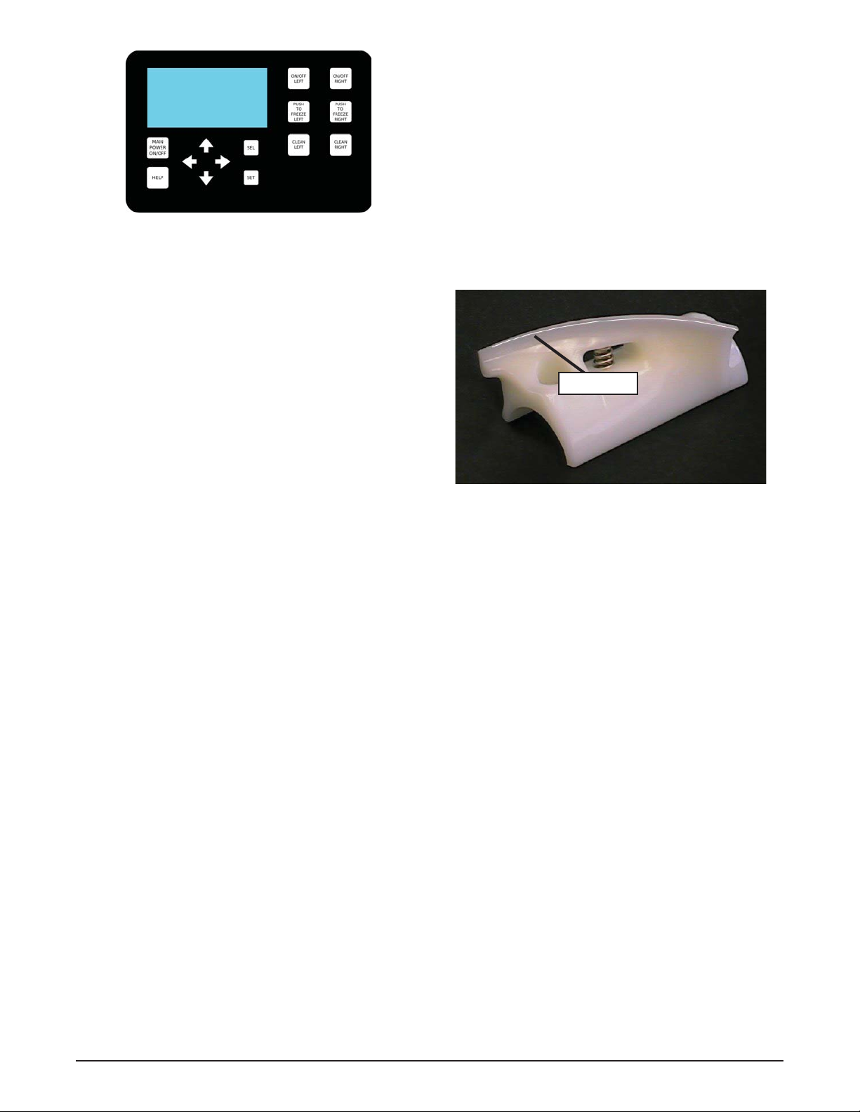
Figure 3-2 IntelliTec2™ Control
Help
Pressing the Help button will display help information
dependant on the cursor’s location. Pressing the Help
button again will exit the help screen.
Selection Button (SEL)
The SEL button is used by technicians to select menu
options.
Set Button (SET)
The SET button is used by technicians to save changes
when modifying control settings.
On/Off Button
Power to the freezing cylinders can then be controlled
with the On/Off Left and On/Off Right switches.
Push to Freeze Button
Pressing the PUSH TO FREEZE button initiates “Serve
Mode”.
Clean Button
The CLEAN button initiates “Clean Mode”.
Arrow Buttons ()
The arrow buttons are used by technicians to navigate
through the control readings and settings.
B. SPIGOT SWITCH
The spigot switch is mounted to the spigot cam assembly
behind the header panel. When the spigot is opened to
dispense product, the spigot switch opens and the “Serve
Mode” begins.
C. DISPENSE RATE ADJUSTOR
The dispense rate adjustor is located under the header
panel, to the immediate right of the spigot handles. Turning
the knob counterclockwise will decrease the dispense rate.
D. MIX LOW LIGHTS
The mix low lights are located at the back of the F231.
There is a light for each freezing cylinder. A steady light
signifi es a low mix condition. A blinking light signifi es an
error. The light will automatically turn off when the condition has been resolved.
E. USB ACCESS PORT
The USB access port is located on the right side panel
of the machine. The port is used by technicians to import
fi rmware and export machine statistics.
3.3 DISASSEMBLY OF MACHINE PARTS
Before using the machine for the fi rst time, complete
machine disassembly, cleaning and sanitizing procedures need to be followed. Routine cleaning intervals
and procedures must comply with the local and state
health codes. Inspection for worn or broken parts should
be made at every disassembly of the machine. All worn
or broken parts should be replaced to ensure safety to
both the operator and the customer and to maintain good
machine performance and a quality product. Check the
wear line on the auger fl ights on a regular basis (Fig.
3-3) and replace as needed. Frequency of cleaning must
comply with the local health regulations.
Wear Line
Figure 3-3 Auger Flight Wear
To disassemble the machine, refer to the following steps:
A. REMOVING MIX
For the fi rst time cleaning the machine, skip to part B.
Disassembly of Front Door.
1. Press the Clean button. After mix has melted
(about 5 minutes) open the spigot to drain the
mix.
2 Fill the hopper with 2 gallons (8 liters) of cool tap
water.
3. Press the Clean button to run the machine. After
30 seconds press the Clean button again to stop
the auger.
4. Drain the water out of the machine.
NOTE
If the water does not drain clear, repeat steps 2-4.
5. Use Stera-Sheen or equivalent sanitizing solution
mixed according to manufacturer’s instructions to
provide a 100 parts per million strength solution.
Mix sanitizer in quantities of no less than 2
gallons of 90° to 110°F (32°C to 43°C) water. Any
sanitizer must be used only in accordance with
the manufacturer’s instructions.
6. Pour the sanitizer into the hopper.
7. Using brushes provided, scrub the hopper.
8. After 5 minutes, drain the sanitizer out of the
freezing cylinder.
Service Manual #513659 10 Model F231
Page 19
B. DISASSEMBLY OF FRONT DOOR
1. Turn the machine off by pressing the Main Freezer
Power Off/On button on the IntelliTec2™ control.
2. Remove the knobs on the front door.
3. Remove the front door by pulling it off the studs.
4. Remove the spigot through the bottom of the front
door.
5. Remove all o-rings from parts by fi rst wiping off
the lubrication using a clean towel. Then squeeze
the o-ring upward to form a loop (Fig. 3-4). Roll
the o-ring out of the groove.
Figure 3-4 Removing O-Ring
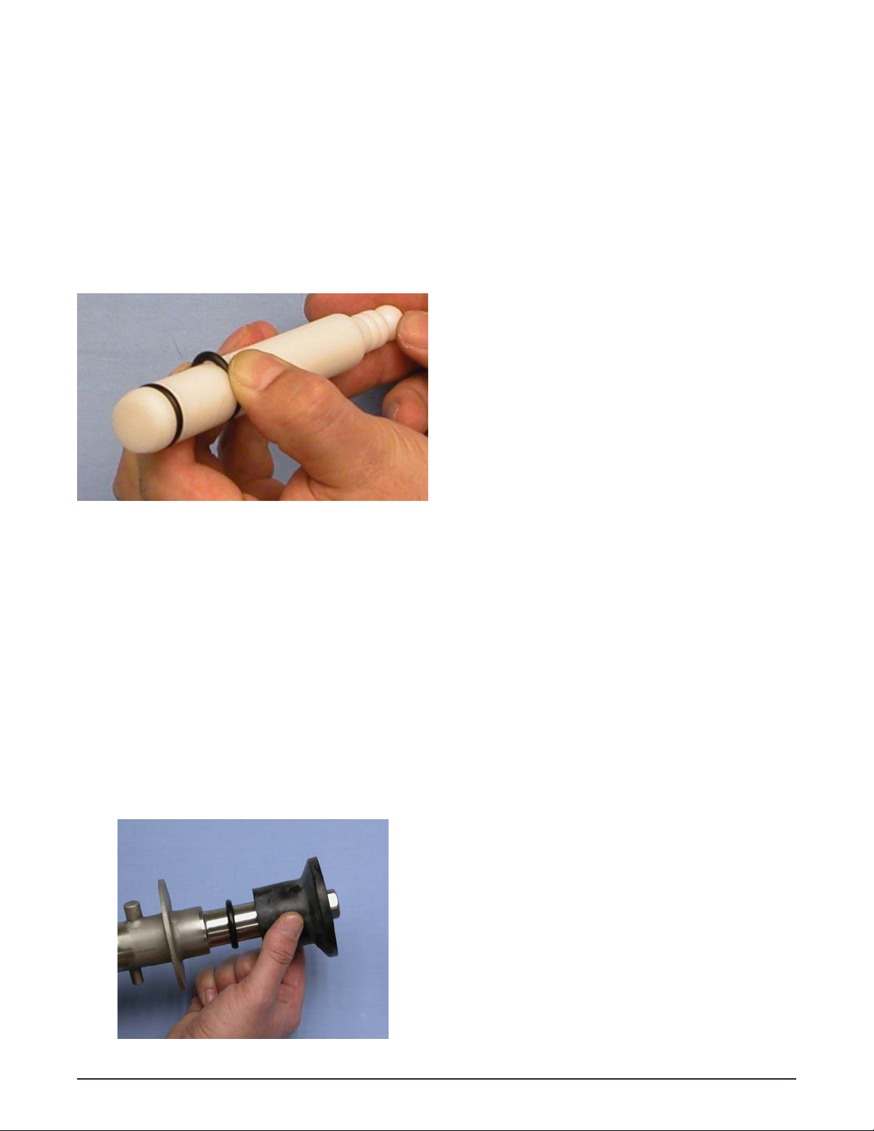
C. DISASSEMBLY OF AUGER
1. Remove the front auger support and bushing.
2. Remove the auger assembly from the machine.
Pull the auger out of the machine barrel slowly.
As the auger is being pulled out, carefully remove
each of the plastic fl ights with springs.
3. Keep the rear of the auger tipped up once it is
clear of the freezing cylinder to prevent the rear
seal assembly from dropping.
4. Wipe the spline lubricant off of the hex end of the
auger with a paper towel. Remove the rear seal
assembly (Fig. 3-5).
5. Unscrew the springs from the auger fl ights.
3.4 CLEANING DISASSEMBLED PARTS
Disassembled machine parts require complete cleaning,
sanitizing and air drying before assembling. Local and state
health codes will dictate the procedure required. Some
state health codes require a four sink process (pre-wash,
wash, rinse, sanitize, air dry), while others require a three
sink process (without the pre-wash step). The following
procedures are a general guideline only. Consult your
local and state health codes for the procedures required
in your location.
A. Prepare Stera-Sheen or equivalent cleaner in
2 gallons of 90° to 110°F (32° to 43°C) water
following manufacturers instructions. Place all
parts in the solution and clean with provided
brushes.
B. Rinse all parts with clean 90° to 110°F (32° to
43°C) water.
C. Wash the hopper and freezing cylinder with the
Stera-Sheen solution and brushes provided.
D. Clean the rear seal surfaces from the inside of the
freezing cylinder with the Stera-Sheen Solution.
3.5 SANITIZING MACHINE PARTS
A. Use Stera-Sheen or equivalent sanitizing solution
mixed according to manufacturer’s instructions to
provide a 100 parts per million strength solution.
Mix sanitizer in quantities of no less than 2
gallons of 90° to 110°F (32°C to 43°C) water. Any
sanitizer must be used only in accordance with
the manufacturer’s instructions.
B. Place all parts in the sanitizing solution for 5
minutes, then remove and let air dry completely
before assembling in machine.
3.6 CLEANING THE MACHINE
The exterior should be kept clean at all times to preserve
the luster of the stainless steel. A high grade of stainless
steel has been used on the machine to ease cleanup. To
remove spilled or dried mix, wash the exterior with 90° to
110°F (32°C to 43°C) Stera-Sheen solution or equivalent
cleaner and wipe dry.
Do not use highly abrasive materials, as they will mar the
fi nish. Use a soft cloth or sponge to apply the solution.
For best results, wipe with the grain of the steel.
A. Clean the rear seal surface from inside of the
freezing cylinder.
Figure 3-5 Rear Seal Assembly
Service Manual #513659 11 Model F231
Page 20

B. Using sanitizing solution and the large barrel
brush provided, sanitize the freezing cylinder by
dipping the brush in the sanitizing solution and
brushing the inside of the freezing cylinder.
NOTE
Do not let sanitizing solution sit overnight in the
freezing cylinder.
C. Remove the drip tray by pulling from the front
panel. Clean and replace the drip tray.
3.7 ASSEMBLING MACHINE
To assemble the machine parts, refer to the following steps:
NOTICE
Petrol-Gel sanitary lubricant or equivalent must be
used when lubrication of machine parts is specifi ed.
NOTICE
The United States Department of Agriculture and
the Food and Drug Administration require that lubricants used on food processing equipment be certifi ed for this use. Use lubricants only in accordance
with the manufacturer’s instructions.
A. Assemble all o-rings onto parts dry, without
lubrication. Then apply a thin fi lm of sanitary
lubricant to exposed surfaces of the o-rings.
B. Lubricate the rear seal area on the auger shaft
with a thin layer of sanitary lubricant. Install the
rear seal o-ring. Lubricate the outside of the rear
seal o-ring with sanitary lubricant.
C. Lubricate the inside metal surface of the rear
seal and install it onto the auger shaft. DO NOT
lubricate the outside of the rear auger seal (Fig.
3-6).
D. Lubricate the hex drive end of the auger with a
small amount of spline lubricant. A small container
of spline lubricant is shipped with the machine.
E. Screw the springs onto the studs in the plastic
fl ights. The springs must be screwed into the
fl ights completely to provide proper compression.
F. Install the two plastic fl ights onto the rear of the
auger and insert it part way into the freezing
cylinder.
G. Install the remaining plastic fl ights, push the auger
into the freezing cylinder and rotate slowly until
the auger engages the drive shaft.
H. Apply a thin layer of sanitary lubricant to the inside
and outside of the auger support bushing. Install
the bushing onto the auger support and install the
auger support into the front of the auger. Rotate
the auger support so that one leg of the support
points straight up.
I. Apply a thin layer of sanitary lubricant to the
o-rings on the spigot body and install the spigot
body through the bottom of the front door.
K. Apply a thin fi lm of sanitary lubricant to the door
seal o-ring and fi t it into the groove on the rear
of the front door.
M. Place the front door assembly on the mounting
studs and the push front door against the machine
carefully.
N. Secure the front door to the machine by placing
the knobs on the studs and tightening until fi nger
tight. Do not overtighten. A proper o-ring seal can
be observed through the transparent front door.
3.8 SANITIZING
Sanitizing must be done after the machine is clean and
just before the machine is fi lled with mix. Sanitizing the
night before is not effective. However, you should always
clean the machine and parts after using it.
NOTE
The United States Department of Agriculture and
the Food and Drug Administration require that all
cleaning and sanitizing solutions used with food
processing equipment be certifi ed for this use.
When sanitizing the machine, refer to local sanitary regulations for applicable codes and recommended sanitizing
products and procedures. The frequency of sanitizing
must comply with local health regulations. Mix sanitizer
according to manufacturer’s instructions to provide a 100
parts per million strength solution. Mix sanitizer in quantities of no less than 2 gallons of 90°F to 110°F (32°C to
43°C) water. Allow sanitizer to contact the surfaces to be
sanitized for 5 minutes. Any sanitizer must be used only
Figure 3-6 Lubricate Rear Seal
Service Manual #513659 12 Model F231
in accordance with the manufacturer’s instructions.
Page 21

A. Prepare 2 gallons of Stera-Sheen sanitizing
solution following the manufacturer’s instructions.
B. Install the mix inlet regulator into the hopper.
C. Pour the sanitizing solution into the hopper.
D. Make sure the display shows the freezing cylinder
is off. If it is not, press the On/Off Left or On/Off
Right button to turn it off.
NOTE
If the freezing cylinder is not off, the control will
not go into Clean mode. This is to protect from accidentally going into Clean mode.
E. Press the CLEAN button.
F. Check for leaks.
1. Check for leaks at the front door seals.
2. Check the drain tray located under the front
door for leaks coming from the rear of the rear
auger seal.
G. Using a sanitized soft bristle brush (or equivalent)
dipped in sanitizing solution, clean the hopper
sides, mix inlet regulator and underside of the
hopper cover.
H. After fi ve minutes, open the spigot to expel
sanitizing solution. Drain all of the solution from
the machine.
I. When the solution has drained, press the CLEAN
button to stop the auger. Allow the freezing cylinder
to drain completely.
The machine is now sanitized and ready for adding mix.
3.9 FREEZE DOWN AND OPERATION
A. Sanitize immediately before use.
B. Make sure the display shows the freezing cylinder
is off. If it is not, press the On/Off Left or On/Off
Right button to turn it off.
C. Fill the hopper with at least 2.5 gallons of mix.
D. Place a container under the spigot and open the
spigot to allow the mix to fl ush out about 8 ounces
(0.23 liters) of sanitizing solution and liquid mix.
E. Press the On/Off button for the cylinder.
F. Press the PUSH TO FREEZE button.
G. When the product is at 75% consistency, the
display will read “SERVE”. Open the spigot to
dispense product.
H. The machine dispenses product at a reasonable
draw rate. If the machine is overdrawn, the result
is a soft product or a product that will not dispense
at all. If this occurs, allow the machine to run for
approximately 30 seconds before dispensing more
product. A dispense rate adjustor is located under
the header panel, to the immediate right of the
spigot handle. Turning the knob counterclockwise
will decrease the dispense rate.
I. Do not operate the machine when the MIX LOW
message is displayed. Refi ll the mix container
immediately.
NOTE
The control has a standby mode for Serve 1 and
a sleep mode for Serve 1 and Serve 2. After a
preset number of freezing cycles in Serve 1, it will
enter the standby mode (followed by sleep mode)
and remain there until someone draws product or
presses the PUSH TO FREEZE button. In Serve 2
the control directly goes into the Sleep 2 mode. In
the sleep mode, the machine will keep the product
below 41°F (5°C). Sleep modes do not take the
place of cleaning and sanitizing. Federal, State,
and local regulatory agencies determine frequency
of cleaning and sanitizing.
3.10 FINE CONSISTENCY ADJUSTMENT
If the product consistency needs to be adjusted, use the
Fine Consistency Adjustment. To access the setting, the
Associate level password must be entered. Follow the
steps below for the Fine Consistency Adjustment.
A. Press the left arrow from the Current Status
screen.
B. Press the right arrow then the SEL button from
the Password screen. After the password is
accepted, move the cursor to the Fine Consistency
Adjustment option and press the SEL button.
C. On the Fine Consistency Adjustment screen, press
the SEL button and use the arrows to modify the
setting. Adjust the Fine Consistency higher to
increase the consistency or lower to decrease
the consistency.
D. Press the SET button to save the changes. Make
adjustments in increments of 5 for best results.
Service Manual #513659 13 Model F231
Page 22

3.11 MIX INFORMATION
Mix can vary considerably from one manufacturer to
another. Differences in the amount of butterfat content
and quantity and quality of other ingredients have a
direct bearing on the fi nished frozen product. A change
in machine performance that cannot be explained by a
technical problem may be related to the mix.
Proper product serving temperature varies from one
manufacturer’s mix to another. Mixes should provide a
satisfactory product in the 20°F to 24°F range. Diet and
low-carb mixes typically freeze to proper consistency at
higher temperatures.
When checking the temperature, stir the thermometer in
the frozen product to get an accurate reading.
Old mix, or mix that has been stored at too high a temperature, can result in a fi nished product that is unsatisfactory.
To retard bacteria growth in dairy based mixes, the best
storage temperature range is between 33° to 38°F (0.5°
to 3.3° C).
Service Manual #513659 14 Model F231
Page 23

SECTION 4
MAINTENANCE AND ADJUSTMENTS
This section is intended to provide maintenance personnel
with a general understanding of the machine adjustments.
It is recommended that any adjustments in this section
be made by a qualifi ed person.
4.1 ACCESSING CONTROL READINGS AND
SETTINGS
The readings and settings on the IntelliTec2™ control are
accessed by using a keypad sequence. Press the left arrow button from the Current Status screen to access the
passcode input screen.
The specifi c readings and parameters available depend
on the keypad sequence entered. The lowest level is
Associate and has limited access. The Manager level
has access to the majority of screens except Utilities (2
of 2). The Technician level has full access to the control
including the Associate and Manager level options.
Following are the keypad sequences for the three levels
available.
Associate Press the right arrow then the SEL button.
Manager Press the right arrow, up arrow then the
SEL button
Technician Press the right arrow, SET, then the SEL
button
4.2 NAVIGATION AND MODIFYING SETTINGS
Navigating through the IntelliTec2™ screens is done with
the arrow keys on the touchpad. After positioning the cursor on a desired menu, press the SEL button to select
that option. If the option is a setting, press the SET button
to change the value. Use the arrow keys to change the
value. Press the SET button to save the changes.
The SEL button changes the cylinder selection on screens
that show the cylinder.
Pressing the left arrow button from any menu will go back
one screen. Pressing the left arrow button at the Main
Menu screen goes to the Current Status screen.
4.3 USER INTERFACE SCREENS
A. Current Status
Current Status 01/01/01
12:34:56
Left Serve
Right Sleep 1
Storage Left On
Storage Right On
The Current Status screen gives an overview of the
machine's operation. It shows the mode of the freezing
cylinders and the storage refrigeration. If there is an error,
the error text description replaces the status information.
The Service Contact Information screen is accessed from
the Current Status screen. Move the cursor to the Service
Contact Information option and press the SEL button.
B. Service Contact Information
Service Contact Information
Name
Stoelting
Telephone Number
920 - 894 - 2293
Unit Serial Number
00000000
Version 00.00/00.00
The Service Contact Information screen provides the
name and telephone number for service. The default is
Stoelting Technical Customer Service. The Manager and
Technician levels can change the default by selecting
the Modify Contact Information option or by uploading
the info.txt fi le.
C. Main Menu
Main Menu
- Technician Level Access
_ Fine Consistency Adjustment
_ Performance
_ Modify Settings
_ Utilities
_ Errors and Statistics
The Main Menu screen provides access to all the readings and settings on the IntelliTec2™ control. To access
the Main Menu, use one of the keypad sequences from
Section 4.1. The example above shows the options available when entering the Manager or Technician keypad
sequence. The Associate will only see the Fine Consistency Adjustment option.
_ Service Company
Service Manual #513659 15 Model F231
Page 24

D. Fine Consistency Adjustment
B. Performance (2 of 2)
Fine Consistency Adjustment
Cylinder Right
Changing the fine consistency
change the firmness of the
product.
Consistency CutIn Limit 00
Consistency CutOut Limit 00
_ Fine Consistency 000
Product consistency can be adjusted by the Associate
level by using the Fine Consistency Adjustment screen.
Increasing the Fine Consistency number increases the
product consistency (fi rmer product).
The Consistency Limits show the Fine Consistency adjustment added to the Consistency number.
4.4 PERFORMANCE SCREENS
A. Performance (1 of 2)
Performance (1 of 2)
Cylinder Right
Consistency 000.00
Cylinder Temp -000.0°F
Motor Amps 00.000A
Input Voltage 000.0V
Performance (2 of 2)
Cylinder Right
Ambient Temp -000.0°F
Storage Temp -000.0°F
Number of Cycles 000
Error Status No Error
The Performance screens display the current status of
the machine. This screen shows the current ambient
temperature, storage temperature and number of cycles
since the Push to Freeze button was pressed or the spigot
was pulled. Press the left arrow to go to the fi rst screen.
4.5 SETTINGS SCREENS
A. Modify Operating Settings
Modify Operating Settings
_ Basic Settings
_ Advanced Settings
_ Storage Settings
_ User Preferences
_ Time and Date
The Performance screens display the current status of
the machine. These screens are available to the Manager
and Technician levels. Press the right arrow to go to the
second screen.
Cylinder
The performance information displayed is for the selected
cylinder. To change cylinders press the SEL button.
Consistency*
This is the current consistency number of the selected
cylinder. The consistency number represents how thick
or thin the product in the freezing cylinder is. A higher
number means the product is thicker. Go to the Modify
Operating Settings menu to change the operating setting.
Cylinder Temperature
This is the current suction line temperature of the selected
cylinder.
Motor Amps*
This is the current motor amps of the selected cylinder.
Input Voltage*
This is the current voltage of the selected cylinder.
* Only shown when the drive motor is running
This menu provides access to view and change the different operating settings on the machine. The Manager and
Technician levels have access to these screens.
B. Basic Settings
Basic Settings
Cylinder Right
_ Enable Control Consist-Consist
_ CutOut Consist Offset 000
_ CutIn Consist Offset 000
_ CutIn Temp 00.0°F
_ CutOut Temp 00.0°F
_ Cycles In Serve Mode 000
This menu contains settings for the control style, CutIn
and CutOut, cycles in serve mode and auger cycle times.
This screen is available to the Technician level.
Service Manual #513659 16 Model F231
Page 25

Cylinder can be changed by pressing the SEL button.
The Enable Control setting determines the cutin and
cutout style. The options are Consistency-Consistency,
Temperature-Consistency or Temperature-Temperature.
Setting the control to Consistency-Consistency enables
Serve 2 Mode (instead of Serve 1 Mode). Serve 2 Mode
extends the post stir to prevent short cycling the compressor and a possible misread of the consistency in the
freezing cylinder.
CutOut Consistency Offset is a number that represents
the point at which a freezing cycle will end in ConsistencyConsistency or Temperature-Consistency style. The
actual cutout value is the sum of this number, the Cutin
Consistency Offset and the Motor Zero Load numbers.
CutIn Consistency Offset is a number that represents
the point at which a freezing cycle will start in ConsistencyConsistency style. The actual cutout value is the sum of
this number and the Motor Zero Load number.
CutIn T emperature is the suction line temperature in the
cylinder when a freezing cycle will start in TemperatureConsistency or Temperature-Temperature style.
CutOut Temperature is the suction line temperature in the
cylinder when a freezing cycle will stop in TemperatureTemperature style.
Cycles In Serve Mode is a count of the number of freez-
ing cycles.
C. Advanced Settings (1 of 2)
Advanced Settings (1 of 2)
Cylinder Right
_ Standby On Time 0000 sec
_ Standby Off Time 0000 sec
_ Standby Time 000 min
_ Stir On 0000 sec
_ Stir Off 0000 sec
The Advanced Settings menu contains standby and
sleep mode adjustments and is available to the Manager
and Technician levels. Press the right arrow to go to the
second screen.
Cylinder can be changed by pressing the SEL button.
The Standby On Time setting determines the length of
the freezing cycle in Standby Mode.
The Standby Off Time setting determines the length
between freezing cycles in Standby Mode.
The Standby Time setting determines the total amount
of time in Standby Mode.
Stir On is the amount of time that the auger rotates during
the stir cycle. Stir cycles occur in Serve Mode, Standby
Mode and Sleep 2 Mode.
Stir Off is the amount of time between stir cycles. Stir
cycles occur in Serve Mode, Standby Mode and Sleep
2 Mode.
D. Advanced Settings (2 of 2)
Advanced Settings (2 of 2)
Cylinder Right
_ Sleep 2 CutIn -00.0°F
_ Sleep 2 CutOut -00.0°F
_ Default Off Time 0000 sec
The Advanced Settings menu contains standby and sleep
mode adjustments and is available to the Manager and
Technician levels. Press the left arrow to go to the fi rst
screen.
Sleep 2 CutIn is the temperature that a freezing cycle
starts in Sleep 2 Mode.
Sleep 2 CutOut is the temperature that a freezing cycle
stops in Sleep 2 Mode.
Default Off Time is the maximum time between freezing
cycles during Serve Mode or Serve 2 Mode.
E. Storage Settings (1 of 2)
Storage Settings (1 of 2)
_ Storage Refirgeration Active
_ Storage CutIn -00.0°F
_ Storage CutOut -00.0°F
_ Storage Degree Offset 00°F
_ Storage Off Time 00 min
_ Storage On Time 0000 sec
This Storage Settings menu contains storage refrigeration
parameters and is available to the Technician level. Press
the right arrow to go to the second screen.
Storage Refrigeration can be set to Active or Suspend.
Active is the normal setting. Suspend is used only for
troubleshooting and setting an AXV. Never have refrigeration set to Suspend during normal operation.
Storage CutIn is the temperature at which the storage
refrigeration cycle starts. This is how warm it will get before
starting a storage refrigeration cycle.
Storage CutOut is the temperature at which the storage
refrigeration cycle stops. This is how low the temperature
will get before ending the storage refrigeration cycle.
The Storage Offset value is added to the storage tem-
perature reading to determine if storage refrigeration
starts with a freezing cycle. This setting helps prevent
short cycling and saves energy.
The Storage Off setting determines the time between
storage refrigeration cycles during a sensor failure.
The Storage On setting determines the length of a stor-
age refrigeration cycle during a sensor failure.
Service Manual #513659 17 Model F231
Page 26

F. Storage Settings (2 of 2)
H. Time and Date
Storage Settings (2 of 2)
_ Storage Max On 00 min
_ Storage Recovery 0 min
_ Storage Too Warm 00.0°F
_ Storage Too Warm 000 min
This Storage Settings menu contains storage refrigeration
parameters and is available to the Manager and Technician levels. Press the left arrow to go to the fi rst screen.
The Storage Max On setting is the maximum time that
a storage refrigeration cycle will run.
The Storage Recovery setting is the minimum time
between storage refrigeration cycles if the Storage Max
On time ends the cycle.
The Storage Too Warm values are the temperature and
amount of time. When the temperature is above the set
temperature for the set period, the Storage too Warm
message will be displayed.
G. User Preferences
Time and Date
Time 00:00:00 AM
Date 00/00/00
Daylight Savings Off
Clock Type 12 HR
Date Format
_ Modify Time and Date
The Time and Date menu shows the time and date settings. The Manager and Technician levels can change the
time and date by using the Modify Time and Date option.
4.6 UTILITIES SCREENS
Utilities (1 of 2)
_ Adjust LCD Contrast
_ Touchpad Lockup
_ Export Machine Stats
_ Clean Options
Next Utilities Menu
User Preferences
_ Language English
_ Temp Units Farenheit(°F)
_ Service Contact Information
_ Contact Information USB Update
The User Preferences menu contains language options,
temperature units, service contact information and touchpad lockup. The screen is available to the Manager and
Technician levels.
The Language setting changes the language displayed.
English and Polish are the only languages currently
available.
The Temperature Units setting changes the units dis-
played to Fahrenheit or Celsius.
The Service Contact Information option is used to change
the service contact details including service company
name and number and machine serial number.
Utilities (2 of 2)
_ Testing and Manual Operation
_ Unit Calibration
_ Clear Log Data
_ Restore Factory Defaults
_ Restore Motor Table Defaults
_ Reset Unit Configuration
The Utilities menu gives access for various settings and
operations in the control. The Utilities menu is available
to the Technician and Manager levels. The Manager level
will only have access to the fi rst screen. The Technician
level has access to both screens.
NOTE
Entering the Utilities (2 of 2) screen automatically
shuts off the freezing cylinders.
A. Product Selection
Product Selection
Cylinder Right
_ Current Product Type 0
CutOut Consistency 000
CutIn Consistency 000
Press Set to change selection
Press Sel to accept selection
Service Manual #513659 18 Model F231
Page 27

The Product Selection screen changes CutIn Consistency and CutOut Consistency to a predetermined value
depending on the product type.
B. Adjust LCD Contrast
Adjust LCD Contrast
0123456789
ABCDEFGHIJKLMNOPQRSTUVWXYZ
ź to change
Press
Ÿ
E. Clean Options
Clean Options
Clean History Log
Clean Warning
Clean Lockout
The Clean Options Menu gives access to the Clean History Log and Clean Lockout options.
The Adjust LCD Contrast screen adjusts the contrast between the background lighting and the text on the screen.
C. Touchpad Lockup
Touchpad Lockup
Touchpad Status: Unlocked
Do you want to lock keys
_ No Unlock Touchpad
_ Yes Lock Touchpad
The Touchpad Lockup is used to lock and unlock the
keypad for self service locations.
D. Export Machine Stats
Export Machine Stats
This will export statistics
data to stats.txt file
Please insert USB flash memory
Are you sure you want to do that
_ No
_ Yes
The Export Machine Stats screen allows you to export
all the data and statistics stored in the control. Connect
a USB fl ash drive to the port on the side of the machine
and select the yes option.
Clean History Log (32 of 32)
Cylinder Right
Clean Log ID 0: 00/00/00
00:00:00
Clean Total Time 000 min
The Clean History Log screen shows the date, time and
duration of the last 32 clean cycles.
Clean Warning
Clean Warning Enabled
This option will
require cylinder cleaning
Are you sure you want to do that
_ No - Cancel Clean Warning
_ Yes - Enable Clean Warning
Clean Lockout
Clean Lockout Disabled
This option will
enforce cylinder cleaning
Are you sure you want to do that
_ No - Cancel Clean Lockout
_ Yes - Enable Clean Lockout
The Clean Warning and Clean Lockout screens are
used to enable the clean warning mode or the clean
lockout mode. When one of the modes is enabled and
the machine is not cleaned within a specifi ed period, the
machine will either display a warning (for warning mode)
or remain in sleep mode and not go into serve mode (for
lockout mode).
Service Manual #513659 19 Model F231
Page 28

F. Testing and Manual Operation
Testing and Manual Operation
Select below for testing
_ Left Output Control
_ Right Output Control
_ Left / Right Monitoring
The Testing and Manual Operation menu provides access
for individual components to be energized to assist with
troubleshooting. There are also test monitoring screens
that provide details of the machine status during testing.
Any energized component will deenergize after leaving
the Testing and Manual Operations menu.
Testing and Manual Ops, Left
_ Drive Motor Off
_ Fan Motor Off
_ Liquid Solenoid Off
_ Compressor Off
_ Refer Solenoid Off
_ Aux Solenoid Off
_ Pump Motor Off
Test Monitoring (1 of 3)
Cylinder Right
CRC Errors Dis/IO 0/6791
Motor Voltage 0.0 V
Motor Current 0.000
I/V Phase Angle 0.0°
Frequency 0.0 Hz
Consistency 0.0
Test Monitoring (2 of 3)
Cylinder Right
CRC Errors Dis/IO 0/12
Ambient Temp +00.0°F
Cylinder Temp +00.0°F
Hopper Temp +00.0°F
Pressure Sensor
Pressure Sw On
Test Monitoring (3 of 3)
Cylinder Right
CRC Errors Dis/IO 0/12
Cabinet Door Closed
Spigot Closed
Door Closed
Hi Pressure No
Liquid Level Low
Selecting Left or Right Output Control goes to a screen
that allows motors, solenoids or the compressor to be
individually activated. Activate by moving the cursor to
the desired component and press the SET button.
Selecting Left/Right Monitoring goes to screens that show
current statistics of the selected cylinder.
The Test Monitoring screens can be used for immediate
feedback when troubleshooting. For example the spigot
switch can be tested by opening the spigot and observing
if the status text changes from "Closed" to "Open".
G. Motor Calibration
Motor Zero Load Calibration
_ Left Press Sel to Start
Current Zero Load 00 W
_ Right Press Sel to Start
Current Zero Load 00 W
The Motor Calibration screen is used when a motor is
replaced or the control fi rmware is updated. Move the
cursor to the correct option and press the SEL button to
calibrate the motor to the control.
Service Manual #513659 20 Model F231
Page 29

I. Clear Log Data
K. Restore Unit Confi guration
Clear Log Data
This will clear the error log
and the statistics.
Are you sure
you want to do that
_ No
_ Yes
The Clear Log Data screen will clear all the errors and
statistics in memory.
J. Restore Factory Defaults / Restore Motor Table
Defaults
Restore Factory Settings
This will reset all machine
settings to the original
factory configurations. Are
you sure you want to do that
_ No
_ Yes
Reset Unit Configuration
This will reset the unit type
and motor types.
Are you sure you want to do that
_ No
_ Yes
The Restore Unit Confi guration screen allows you to
change the motor type default. See section 4.8 for details.
4.7 ERRORS & STATISTICS SCREENS
The Errors & Statistics menu gives the Technician access
to machine statistics and error history.
Errors and Statistics
_ Machine Statistics
_ Error History
Restore Motor Table Defaults
This will reset all motor
tables to the original
factory configurations. Are
you sure you want to do that
_No
_Yes
The Restore Factory Defaults and Restore Motor Table
defaults screens allow you to restore the control to the
factory confi gurations.
A. Machine Statistics (1 of 10)
Machine Statistics (1 of 10)
Cylinder Right
Time in Serve Mode 0000 hr
Last 24hrs 0000 min
Last 7days 0000 hr
Time in Off Mode 0000 hr
Last 24hrs 0000 min
Last 7days 0000 hr
The Machine Statistics screen 1 of 10 shows the time in
serve mode and time in sleep mode. The screen shows
a running total, the total for the previous day and the total
for the previous week for both statistics.
Service Manual #513659 21 Model F231
Page 30

B. Machine Statistics (2 of 10)
E. Machine Statistics (5 of 10)
Machine Statistics (2 of 10)
Cylinder Right
Total Low Mix Run 0000 hr
Last 24hrs 0000 min
Last 7days 0000 hr
The Machine Statistics screen 2 of 10 shows the low mix
running time. This is the total time, including serve mode
and sleep mode, that the freezing cylinder was operating
with a low mix error. The screen shows a running total,
the total for the previous day and the total for the previous week.
C. Machine Statistics (3 of 10)
Machine Statistics (3 of 10)
Cylinder Right
Last Clean Cycle 00/00/00
00:00:00 AM
Last Clean Total Time 0000 min
Machine Statistics (5 of 10)
Cylinder Right
Estimated Serve Amount 0000 gal
Last 24hrs 0000 gal
Last 7days 0000 gal
Last Serve Reset 00/00/00
00:00:00 AM
_ Reset Serve Amount
The Machine Statistics screen 5 of 10 gives the estimated
serve amount of the freezing cylinder based on the time
the spigot is open during serve mode. The estimation is
also calculated for the previous day and the previous week.
The screen gives an option to reset the serve amount and
shows when the last reset was done.
F. Machine Statistics (6 of 10)
Machine Statistics (6 of 10)
Cylinder Right
Compressor Run Time 0000 hr
Compressor Cycles 0000
Last Compressor Reset 00/00/00
00:00:00
_ Reset Compressor Time
The Machine Statistics screen 3 of 10 provides the time
and date that the freezing cylinder was last cleaned. This
value is recorded when the Clean button is pressed on
the touchpad. The screen also shows how long the most
recent clean mode lasted.
D. Machine Statistics (4 of 10)
Machine Statistics (4 of 10)
Cylinder Right
Spigot Open Total 0000 min
Last 24hrs 0000 min
Last 7days 0000 min
Spigot Total Cycles 0000
Average Spigot Open 0000 sec
The Machine Statistics screen 4 of 10 shows the total time
that the spigot has been open during serve mode. The
screen shows a running total, the total for the previous
day and the total for the previous week. The screen also
shows the total times that the spigot has been opened.
The Machine Statistics screen 6 of 10 shows the total
run time for the compressor and counts the total cycles.
There is an option to reset the timer and the screen shows
when the last reset was done. The reset should be used
if the compressor is changed.
G. Machine Statistics (7 of 10)
Machine Statistics (7 of 10)
Cylinder Right
Motor Run Time 0000 hr
Motor Cycles 0000
Last Motor Reset 00/00/00
00:00:00 AM
_ Reset Motor Time
The Machine Statistics screen 7 of 10 shows the total run
time for the drive motor and counts the total cycles. There
is an option to reset the timer and the screen shows when
the last reset was done. The reset should be used if the
drive motor is changed.
Service Manual #513659 22 Model F231
Page 31

H. Machine Statistics (8 of 10)
K. Error History
Machine Statistics (8 of 10)
Cylinder Right
Pump Run Time 0000 hr
Pump Cycles 0000
Last Pump Reset 00/00/00
00:00:00 AM
_ Reset Pump Time
The Machine Statistics screen 8 of 10 shows the total run
time for the pump and counts the total cycles. There is
an option to reset the timer and the screen shows when
the last reset was done. The reset should be used if the
pump is changed.
I. Machine Statistics (9 of 10)
Machine Statistics (9 of 10)
Cylinder Right
Current Hose Usage 0000 hr
Hose Service Limit 100 hr
Last Hose Reposition 00/00/00
00:00:00 AM
_ Reset Hose Service Time
The Machine Statistics screen 9 of 10 shows the amount
of time the pump hose has been in use and when the
last reposition was completed. There is also an option to
reset the hose timer.
J. Machine Statistics (10 of 10)
Machine Statistics (10 of 10)
Last Unit Power Up 00/00/00
00:00:00
Avg Power KWH/Day 0 Watts
The Machine Statistics screen 10 of 10 shows when the
machine was last powered on. The screen also gives an
average power consumption per day.
Error History 25 of 25
Type Cylinder Sensor
Date 00/00/00 00:00:00 AM
Cylinder Right
_ Status At Time of Error
_ Help
The Error History screen shows the last error that occurred.
The screen shows the type of error, the time and date and
the cylinder that had the error. Up to 25 errors are stored.
Press the up or down arrow to scroll through the errors.
Select the Status at Time of Error option to view data for
the time the error occurred. The Help option explains the
error and provides quick troubleshooting tips.
L. Status at Time of Error
Status at Time of Error
Operating Mode Off
Mix Levels Full Level
Consistency 000.00
Input Voltage 000.0V
Motor Amps 00.000A
Ambient Temp -000.0°F
Cylinder Temp -000.0°F
The Status at Time of Error screen gives data for the time
the error occurred.
4.8 UPDATING FIRMWARE
Before starting, make sure there is liquid mix or water in
the freezing cylinder. The calibration steps should not be
completed with frozen product in the freezing cylinders.
Firmware is contained in a .rom fi le which can be down-
loaded from the extranet website or sent via email. Download the .rom fi le onto the top level of a USB drive (don't
put the fi le in a folder and don’t change the name of the
fi le) and follow the instructions below.
A. Unplug the machine from electrical power.
NOTE
On a dual power supply machine, unplug both sides.
Service Manual #513659 23 Model F231
Page 32

B. Connect the USB fl ash drive to the port on the
machine. Depending on the model, the USB port
will be located:
1. On the side of the machine. Remove the plug.
2. Behind the header panel. Remove the panel
and locate the USB connector on the display
module.
E. Connect power to the machine. On a dual power
supply machine, only the left side needs to be
connected.
F. The display should say "Stoelting Foodservice
Equipment" in a large font and the new fi rmware
version will be displayed at the bottom.
NOTE
If the display does not show the "Stoelting Foodservice Equipment" text, make sure the .rom fi le
is in the top level of the USB fl ash drive. The .rom
fi le cannot be in any folders within the fl ash drive.
G. From the Current Status screen, press the left
arrow button to get to the passcode entry screen.
H. Enter the technician password to the control by
pressing the right arrow, SET, then the SEL button.
I. Navigate to the Utilities menu and select the Next
Utilities Menu.
J. Go to the Reset Unit Confi guration option and
press the SEL button.
K. On the Reset Unit Confi guration screen select
the Yes option and press the SEL button.
L. Confi rm the control settings are the same as the
values in the table below:
Machine Machine Type Motor Type
F231-18 2 2
F231-38 2 2
F231-109 2 3
F231-309 2 3
Q. Go to the Motor Zero Load Calibration option and
press the SEL button.
NOTE
Calibration must be done with water or liquid mix
in the freezing cylinder. Do not try to calibrate with
frozen mix in the freezing cylinder.
R. Press the SEL button to calibrate the motors for
both freezing cylinders.
NOTE
If the motors do not start, cycle the power and try
again.
S. Press the left arrow to exit the Utilities menu and
go the Main Menu screen.
T. Go to the Modify Settings screen, scroll to the
User Preferences option and press SEL at the
Service Contact Information screen.
U. Scroll to the serial number and press the SET
button. Enter the serial number for the machine by
scrolling through the numbers. The serial number
is found on the information plate located on the
side or back of the machine. If the last digit is a
blank, scroll past the “z” for the blank space.
4.9 DRIVE BELT TENSION ADJUSTMENT
To check belt tension, refer to Figure 4-1 and follow the
steps below:
WARNING
Hazardous voltage
Make sure the machine is off when disassembling
for servicing. The machine must be disconnected
from electrical supply before removing any access
panel. Failure to disconnect power before servicing
could result in death or serious injury.
Machine & Motor Types
M. Scroll the cursor down to the Accept option
and press the SEL button. The screen will read
“Restoring EEPROM”. This process takes about
three minutes.
N. Once the control has completed this step, it will
automatically restart.
O. Enter the technician password to the control by
pressing the right arrow, SET, then the SEL button.
P. Navigate to the Utilities menu and select the Next
Utilities Menu.
Service Manual #513659 24 Model F231
Tension
Adjustment
Nut
Figure 4-1 Belt Tension Adjustment
Page 33

A. Remove the back panel.
B. Use a Burroughs Belt Tension Gauge to set the
tension for the drive belt. Set the belt tension to
40-45 lbs.
C. If an adjustment is necessary, loosen the four
motor plate retaining nuts, adjust belt tension
then retighten the four nuts.
D. Using a straightedge, check that the drive motor
pulley is aligned with the speed reducer pulley.
Align the pulley if necessary.
NOTE
Belt life will be increased if new drive belts are
tightened after two or three weeks of operation.
4.10 CONDENSER CLEANING (AIR-COOLED
MACHINES)
The F231 has an air-cooled or water-cooled condenser.
The air-cooled condenser is a copper tube and aluminum
fi n type. Condensing is totally dependent upon airfl ow. A
plugged condenser, or restrictions in the louvered panel will
restrict airfl ow. This will lower the capacity of the system
and damage the compressor. The condenser must be
kept clean of dirt and grease. The machine must have a
minimum of 3” (7.6 cm) of ventilation on the sides of the
unit for free fl ow of air. Make sure the machine is not pulling
over 100° F (37° C) air from other equipment in the area.
The water-cooled condenser is a tube and shell type. The
condenser needs a cool, clean supply of water to properly
cool the machine, inlet and discharge lines must be 3/8”
I.D. minimum.
The air-cooled condenser requires periodic cleaning. To
clean, refer to the following procedures.
A. Visually inspect the condenser for dirt.
B. If the condenser is dirty, place a wet towel over
the condenser.
C. Using compressed air or CO2 tank, blow out the
dirt from the back of the condenser. Most of the
dirt will cling to the wet towel.
D. An alternative method is to clean with a condenser
brush and vacuum.
NOTE
If the condenser is not kept clean, refrigeration effi ciency will be lost.
4.11 PREVENTATIVE MAINTENANCE
It is recommended that a preventative maintenance
schedule be followed to keep the machine clean and
operating properly. The following steps are suggested as
a preventative maintenance guide.
The United States department of agriculture and the food
and drug administration require that lubricants used in
food zones be certifi ed for this use. Use lubricants only
in accordance with the manufacturer’s instructions.
A. Daily checks
Check for any unusual noise or condition and
repair immediately.
B. Monthly checks
Check the condenser for dirt and clean if
necessary.
C. Quarterly Checks
Check drive belts for wear and tighten belts if
necessary.
4.12 EXTENDED STORAGE
Refer to the following steps for storage of the machine
over any long period of shutdown time:
A. Clean all the parts that come in contact with mix
thoroughly with a warm detergent water. Rinse
in clear water and dry all parts. Do not sanitize.
NOTE
Do not let cleaning solution stand in the freezing
cylinder or hopper during the shutdown period.
B. Remove, disassemble, and clean the front door,
and auger shaft. Leave disassembled during the
shutdown period.
C. Place the auger fl ights and auger support bushing
in a plastic bag with a moist paper towel. This will
prevent them from becoming brittle if exposed to
dry air over an extended period of time (over 30
days).
Service Manual #513659 25 Model F231
Page 34

Service Manual #513659 26 Model F231
Page 35

SECTION 5
!
!
"
#$!#
"!
%&'()&'
%&'*
%
*
+!
,-
"#
"!
.'-
.'-
,/0123
,-
#$!#
"!
)
!
#$!#
"!
)
4!
%*
%&'*
%
*
+!
,-
.'-
"#
"!
)
4!
)
4!
)
4!
%&'()&'
REFRIGERATION SYSTEM
5.1 REFRIGERATION SYSTEM
The F231 refrigeration systems have two functions:
Medium-Temperature - Maintaining mix
temperature in the hopper.
Low-Temperature - Producing and maintaining
high quality product in the freezing cylinders.
The system is designed for effi cient use with R404A
refrigerant. The proper charge is indicated on the information plate.
5.2 REFRIGERANT RECOVERY AND
EVACUATION
Refer to the following procedures to properly recover and
evacuate the refrigeration system. Do not purge refrigerant into the atmosphere.
NOTE
For qualifi ed service personnel only. Anybody work-
ing with refrigerants must be certifi ed as a T echni-
cian TYPE I as required by 40 CFR 82 Subpart F
and hold all State and/or local refrigerant handling
certifi cations. In addition, all handling, storage, and
disposal of refrigerants must be in accordance with
Environmental Protection Agency (EP A) guidelines
and standards and all State and local guidelines
and standards.
WARNING
Hazardous voltage
Make sure the machine is off when disassembling
for servicing. The machine must be disconnected
from electrical supply before removing any access
panel. Failure to disconnect power before servicing
could result in death or serious injury.
Figure 5-1 Water Cooled Refrigeration System
Service Manual #513659 27 Model F231
Page 36

A. REFRIGERANT RECOVERY
1. Disconnect the machine from electrical supply
before removing any panels for servicing.
2. Remove all panels.
3. Connect the recovery unit to the suction and
discharge service valves of the compressor.
4. Connect power to the machine.
5. Turn the machine on by pressing the Main Power
Off/On button.
6. Press the right arrow, SET, then the SEL button
to access the technician level on the control.
7. Activate the Liquid Solenoid and the Refer
Solenoid on the left side and right side. Activating
the solenoids is done through the Left Output
Control and Right Output Control menus which are
located under Utilities in the Testing and Manual
Operation screen. Refer to Section 4 for details.
CAUTION
The solenoid valves must be energized to allow all
refrigerant to be recovered and to prevent injury
when brazing.
8. Evacuate the system until the gauge reads 300
microns of mercury (300μ Hg) for 5 continuous
minutes.
10. If the system will not maintain a standing vacuum
test with the vacuum pump off (gauge increases
towards atmosphere), fi nd the leak, fi x it, and
evacuate again.
11. After evacuating is complete, deactivate the
solenoids by exiting the Testing and Manual
Operation screens.
5.3 REFRIGERANT CHARGING
Refer to the following procedures to properly charge
the refrigeration system. Stoelting recommends liquid
refrigerant charging.
NOTE
For qualifi ed service personnel only. Anybody work-
ing with refrigerants must be certifi ed as a T echni-
cian TYPE I as required by 40 CFR 82 Subpart F
and hold all State and/or local refrigerant handling
certifi cations. In addition, all handling, storage, and
disposal of refrigerants must be in accordance with
Environmental Protection Agency (EP A) guidelines
and standards and all State and local guidelines
and standards.
8. Operate the recovery unit per manufacturer’s
instructions
9. After recovery is complete, deactivate the
solenoids by exiting the Testing and Manual
Operation screens.
B. EVACUATING THE REFRIGERATION SYSTEM
1. Close any open ports in the refrigeration system.
2. Connect a vacuum gauge to one of the Schrader
valves next to an evaporator.
3. Connect the evacuation unit to the suction and
discharge service valves of the compressor.
4. Connect power to the machine.
5. Turn the machine on by pressing the Main Power
Off/On button.
6. Press the right arrow, SET, then the SEL button
to access the technician level on the control.
7. Activate the Liquid Solenoid and the Refer
Solenoid on the left side and right side. Activating
the solenoids is done through the Left Output
Control and Right Output Control menus which are
located under Utilities in the Testing and Manual
Operation screen. Refer to Section 4 for details.
A. Ensure the electrical supply has been removed
before continuing.
B. If the system has been opened or if there was a
leak, refer to Section 5.2 - Refrigerant Recovery
and Evacuation to evacuate the system prior to
charging.
C. Refer to machine’s information plate for total
charge requirements.
NOTE
The refrigeration systems of F231 is critically
charged. Be sure to charge the system to the weight
listed on the machine’s information plate.
D. For liquid refrigerant charging, connect refrigerant
cylinder to the discharge Schrader valve of the
compressor.
E. Energize all fi ve solenoid valves. There are three
liquid line solenoids and two suction line solenoids.
F. Add the proper amount of refrigerant according
to the machine’s information plate.
Service Manual #513659 28 Model F231
Page 37

5.4 COMPRESSOR
The F231 has a hermetic reciprocating compressor (Refer
to Figure 5-2).
Figure 5-2 Compressor
A. WINDING TEST
To test the compressor motor windings for possible problems, perform the following steps:
A. Disconnect the machine from electrical supply
WARNING
Hazardous voltage
Make sure the machine is off when disassembling
for servicing. The machine must be disconnected
from electrical supply before removing any access
panel. Failure to disconnect power before servicing
could result in death or serious injury.
before removing any panels for servicing.
B. Remove the front panel.
C. Remove the protective cover from the compressor
terminals. Disconnect the three terminals; C
(common), R (run), and S (start).
D. Connect an ohmmeter to the C and R terminals
on the compressor. Resistance through the run
winding should be 1.16±10%.
E. Connect an ohmmeter to the C and S terminals
on the compressor. Resistance through the start
winding should be 3.10±10%.
F. To check if windings are shorted to ground, connect
one ohmmeter lead to a bare metal part on the
compressor (such as any copper line leading to
or from the compressor) and check terminals C,
R, and S.
NOTE
The compressor is equipped with an internal overload protector. If the compressor is warm and ohmmeter readings indicate an open winding, allow up
to one hour for overload to reset.
B. COMPRESSOR REMOVAL
A. Disconnect the machine from electrical supply
before removing any panels for servicing.
B. Remove the front panel.
C. Remove the protective cover from the compressor
terminals and disconnect the wires.
D. Recover refrigerant charge per the instructions
in Section 5.2.
E. Leave the suction and discharge ports open to
prevent pressure buildup during compressor
removal.
F. Remove six inches of insulating tubing on
the suction line going to the compressor and
unsweat the suction and discharge line from the
compressor.
G. Remove the four nuts and washers from the base
of the compressor.
H. Remove the compressor through the front of the
machine.
I. Remove the four rubber compressor mounts from
the compressor.
J. Crimp and braze all open ports of the old
compressor.
NOTE
A compressor returned to Stoelting with any open
ports will void the warranty. ALWAYS crimp and
braze ports on a compressor that has been removed.
C. COMPRESSOR INSTALLATION
A. Make sure the machine is disconnected from the
electrical supply before removing any panels for
servicing.
B. Install the four rubber mounts on the compressor.
C. Install the compressor into the machine, fi tting
the base over the four bolt holes.
D. Install the four washers and nuts onto the bolts
and tighten securely.
Service Manual #513659 29 Model F231
Page 38

E. Remove all tubing plugs from the replacement
compressor.
NOTE
The compressor plugs protect the compressor from
moisture in the air. Do not remove the plugs until
you are ready to install. The compressor must not
be opened to the atmosphere for more than 10
minutes.
F. Leave the suction and discharge ports open to
prevent pressure buildup. Braze the suction and
discharge line to the compressor.
G. Connect the wires to the compressor terminals.
H. Replace the drier per the instructions in Section
5.9.
I. Evacuate the system per the instructions in Section
5.2
J. Recharge the system per the instructions in
Section 5.3.
K. Replace the insulating tubing on the suction line.
5.5 CONDENSER
The F231 comes with either an air-cooled or a watercooled condenser. The capacity of the machine is directly
related to keeping the condenser clean and free of debris.
The air-cooled condenser is a copper tube and aluminum
fi n type. The machine must have a minimum of 3” of clearance on both sides for proper air fl ow.
The water-cooled condenser is a tube and shell type. This
condenser requires cool, clean water to function properly.
Inlet and discharge lines must be 3/8” ID minimum.
CONDENSER TESTING
The condenser can be checked for leaks using the bubble
test or using a leak detector.
5.6 VALVES
A. THERMOSTATIC EXPANSION VALVE (TXV)
The Thermostatic Expansion Valve (TXV) is used to
meter the refrigerant to the freezing cylinder evaporator.
It does so by maintaining constant superheat at the exit
of the evaporator. The self-regulating TXV is preset by
the manufacturer and adjustment is not recommended.
Figure 5-3.
TXV TESTING & ADJUSTMENT
NOTE
The bulb has an indent which must be positioned
against the tubing. Good contact between the
bulb and the suction line is necessary for proper
operation of the valve. The bulb must also be well
insulated.
A. Connect a gauge to the Schrader valve on the
suction line.
B. Connect a thermocouple to the suction line next
to the evaporator.
C. Immediately before the refrigeration cycle ends,
the gauge should read between 18-22 psig. The
superheat should be 7-10°F.
D. If the pressure reading is higher than expected
and the superheat is low, check to see if there is
an overcharge of refrigerant.
E. If the pressure reading is lower than expected and
the superheat is high, check to see if there is a
low refrigerant charge or if there is a restriction
in the system.
NOTE
The TXV is the LAST component to adjust in the
refrigeration system.
F. The TXV can be adjusted after the steps above are
completed. When adjusting, do not turn the valve
over 1/4 turn (90°). Turn the valve stem clockwise
to increase the superheat or counterclockwise to
decrease the superheat.
TXV REMOVAL
A. Disconnect the machine from electrical supply
before removing any panels for servicing. Remove
the front panel.
B. Recover refrigerant charge per instructions in
Section 5.2.
C. Leave the suction and discharge ports open to
prevent pressure buildup during TXV removal.
D. Remove any insulation from the TXV and
immediate surrounding lines.
E. Apply a heat sink (wet cloth) to the valve dome
(Figure 5-4).
F. Unsweat the TXV and remove.
Figure 5-3 TXV Figure 5-4 TXV Removal
Service Manual #513659 30 Model F231
Page 39

TXV REPLACEMENT
To replace the TXV, perform the following procedures:
A. Position the TXV, with a heat sink, into the system.
B. With the suction and discharge ports open, braze
the TXV into the system.
C. Remove the heat sink from the TXV.
E. Replace insulation to the TXV and surrounding
lines.
F. Replace the drier per the instructions in Section
5.9.
G. Evacuate the system per the instructions in Section
5.2.
H. Recharge the system per the instructions in
Section 5.3.
B. AUTOMATIC EXPANSION VALVE (AXV)
The Automatic Expansion Valve (AXV) is in OT2, YG2 and
YG2ME models and is used to meter the refrigerant to the
freezing cylinder evaporator. It does so by maintaining a
constant pressure in the evaporator. The self-regulating
AXV is preset by the manufacturer and adjustment is not
recommended. Figure 5-5.
Figure 5-5 AXV
AXV TESTING & ADJUSTMENT
When testing an AXV, isolate the evaporator from the
other evaporators:
To test the left side AXV, turn the right side freezing cylinder
OFF and turn the Aux Solenoid off in the control under
the Testing and Manual Ops screen.
If checking the right side AXV, turn the left side freezing
cylinder OFF and turn the Aux Solenoid off in the control
under the Testing and Manual Ops screen..
A. Connect a gauge to the Schrader valve on the
suction line next to the evaporator.
B. Connect a thermocouple to the suction line next
to the evaporator.
C. Immediately before the refrigeration cycle ends,
the gauge should read the following:
OT2 Models: 22-24 psig
YG2 Models: 23-25 psig
YG2ME Models: 18-20 psig
This reading is based on a full load in the freezing
cylinder.
D. If the pressure reading is higher than expected,
check to see if there is an overcharge of refrigerant.
E. If the pressure reading is lower than expected,
check to see if there is a low refrigerant charge
or if there is a restriction in the system.
NOTE
The AXV is the LAST component to adjust in the
refrigeration system.
F. The AXV can be adjusted after the steps above
are completed. When adjusting, do not turn the
valve over 1/4 turn (90°). Turn the valve stem
clockwise to decrease the evaporator pressure
or counterclockwise to increase the evaporator
pressure.
AXV REMOVAL
A. Disconnect the machine from electrical supply
before removing any panels for servicing. Remove
the side panels.
B. Recover refrigerant charge per instructions in
Section 5.2.
C. Leave the suction and discharge ports open to
prevent pressure buildup during AXV removal.
D. Remove any insulation from the AXV and
immediate surrounding lines.
E. Apply a heat sink (wet cloth) to the valve dome.
F. Unsweat the AXV and remove.
AXV REPLACEMENT
To replace the AXV, perform the following procedures:
A. Position the AXV, with a heat sink, into the system.
B. With the suction and discharge ports open, braze
the AXV into the system.
C. Remove the heat sink from the AXV.
E. Replace insulation to the AXV and surrounding
lines.
F. Replace the drier per the instructions in Section
5.9.
G. Evacuate the system per the instructions in Section
5.2.
H. Recharge the system per the instructions in
Section 5.3.
Service Manual #513659 31 Model F231
Page 40

C. CHECK VALVE
The machine has 3 magnetic check valves (Refer to
Figure 5-6). Each valve is positioned in the suction line
and prevents backfl ow of refrigerant into the evapora-
tor. If there is reversed fl ow, the product in the freezing
cylinder softens and liquid refrigerant can fl ood into the
compressor on startup.
If a check valve needs to be replaced, use a heat sink (wet
cloth) when installing the new valve to prevent damage.
Figure 5-6 Check Valve
D. HIGH PRESSURE CUTOUT
The high pressure cutout stops the compressor if the
discharge pressure reaches the cutout, 445 psig for the
freezing cylinders. It is an automatic reset when the pressure drops below 350 psig.
C. High pressure cutout should trip when pressure
reaches 445 psig ±9.
HIGH PRESSURE CUTOUT REMOVAL
A. Remove the left side panel.
B. Recover refrigerant charge per instructions in
Section 5.2.
C. Leave the suction and discharge ports open to
prevent pressure buildup during removal.
D. Unsweat capillary tube from suction line.
E. Disconnect terminals from high pressure cutout.
HIGH PRESSURE CUTOUT REPLACEMENT
A. With the suction and discharge ports open, braze
the capillary tube to the discharge line.
C. Replace the drier per the instructions in Section
5.9.
D. Braze bulb into place on suction line.
E. Evacuate the system per the instructions in Section
5.2.
F. Recharge the system per the instructions in
Section 5.3.
G. Connect the terminals to the high pressure cutout.
H. Attach the high pressure cutout using the two
screws with star washers.
E. HOT GAS BYPASS
The hot gas bypass valve is installed parallel to the compressor and helps to regulate the compressor temperature
(Refer to Figure 5-8). When the cab evaporator is the only
part of the system requiring refrigerant, the bypass valve
will allow discharge gas to bypass into the suction line to
prevent liquid refrigerant from entering the compressor.
Figure 5-7 High Pressure Cutout
HIGH PRESSURE CUTOUT TEST
A. Connect a gauge to the Schrader valve on the
discharge line.
B. Disconnect cooling:
In a water-cooled machine, shut off the water
supply.
In an air-cooled machine, shut off the fan motor
in the IntelliTec2™ control. Refer to Section 4.6
for details.
Service Manual #513659 32 Model F231
Figure 5-8 Hot Gas Bypass
Page 41

HOT GAS BYPASS ADJUSTMENT
Adjustment to the hot gas bypass must be made when the
hopper refrigeration is the only part of the system running.
NOTE
Before adjusting the hot gas bypass, check the EPR
valve and adjust if necessary.
A. Turn the machine off by pressing the Main Power
On/Off button.
B. Connect a gauge to the Schrader valve on the
suction line next to the compressor.
C. Wait until the gauge stops moving.
D. Unscrew the seal cap from the top of the valve.
E. Using a 5/16” Allen wrench, adjust the valve
counterclockwise to decrease pressure and
clockwise to increase pressure.
NOTE
Each 360° turn will change the pressure about 6
psig.
F. Adjust the hot gas bypass valve to 14 psig ±1.
G. Wait 2 minutes to ensure pressure remains stable.
H. Hand-tighten seal cap to valve.
HOT GAS BYPASS REMOVAL
A. Remove the left side panel.
B. Recover refrigerant charge per instructions in
Section 5.2.
C. Remove insulation around hot gas bypass and
tubing.
D. Leave the suction and discharge ports open to
prevent pressure buildup during hot gas bypass
removal.
E. Apply a heat sink (wet cloth) to the hot gas bypass.
F. Unsweat the hot gas bypass and remove.
HOT GAS BYPASS REPLACEMENT
To replace the hot gas bypass, perform the following
procedures:
A. Apply a heat sink (wet cloth) to the hot gas bypass.
B. With an open port, braze the hot gas bypass into
the system.
C. Remove the heat sink from the hot gas bypass.
D. Replace the fi lter drier. Refer to Section 5.8 for
details.
E. Evacuate and recharge system per instructions
in Section 5.2.
F. EVAPORATOR PRESSURE REGULATOR (EPR)
There is one EPR in the refrigeration system (Refer to
Figure 5-9). It is located on the suction line of the hopper
evaporators and regulates evaporator refrigerant pressure.
Figure 5-9 EPR Valve
EPR TEST AND ADJUSTMENT
Adjustment to the EPR must be made when the hopper
refrigeration is the only part of the system running
A. Turn the machine off by pressing the Main Power
Off/On button.
B. Connect a gauge to the Schrader valve on the
suction line between the hopper evaporators and
the EPR.
C. Press the Main Power OFF/ON button to turn the
machine power on. Listen for the compressor to
start a cycle for the hopper.
D. If the gauge does not read 69 ±1 then adjustment
is needed.
F. Remove the plastic cap and loosen the locknut
on the EPR. Using a small screwdriver, turn the
adjustment screw counterclockwise 1/2 turn, then
adjust as necessary. Turn the valve stem clockwise
for higher pressure or counterclockwise for lower
pressure.
G. Allow the system to stabilize for 5 minutes to
ensure pressure remains stable.
EPR REMOVAL
A. Remove the left side panel and front panel.
B. Recover refrigerant charge per instructions in
Section 5.2.
C. Leave the suction and discharge ports open to
prevent pressure buildup during EPR removal.
D. Unsweat the EPR and remove.
EPR REPLACEMENT
To replace the EPR, perform the following procedures:
A. Apply a heat sink (wet cloth) to the EPR.
B. With an open port, braze the EPR into the system.
C. Remove the heat sink from the hot gas bypass.
D. Replace the fi lter drier. Refer to Section 5.8 for
details.
E. Evacuate and recharge system per instructions
in Section 5.2.
Service Manual #513659 33 Model F231
Page 42

G. WATER V ALVE (W A TER COOLED MODELS ONLY)
The water valve monitors refrigerant pressure and opens
on an increase of pressure. The opening point pressure
is the refrigerant pressure required to lift the valve disc
off the valve seat. (Figure 5-10)
Figure 5-10 Water Valve
WATER VALVE ADJUSTMENT
A. Remove the right side panel.
B. Connect a gauge to the compressor discharge
Schrader valve.
C. Connect the machine to the electrical supply, start
the refrigeration cycle, and read the pressure.
D. The proper gauge reading should be 225-235 psig.
The exit water temperature should be 95-107°F.
E. If the water temperature and high side pressure
are too low, the opening point pressure should
be increased to slow the water fl ow. Turn the
adjustment screw counterclockwise.
F. If the water temperature and high side pressure
are too high, the opening point pressure should
be decreased to increase the fl ow of water. Turn
the adjustment screw clockwise.
WATER VALVE REMOVAL
The water valve is connected to the refrigeration system
by capillary tube brazed to the discharge line.
A. Turn off and disconnect the water supply. Blow
out the water lines with compressed air or CO
.
2
B. Recover refrigerant charge per instructions in
Section 5.2.
C. Leave the suction and discharge ports open
to prevent pressure buildup during water valve
removal.
D. Unsweat the capillary tube from the discharge
line.
E. Remove the clamps from the water lines at the
valve.
F. Remove the two screws holding the water valve
to the frame and remove the valve.
WATER VALVE REPLACEMENT
To replace the water valve, perform the following procedures:
A. Position the water valve and attach to the frame
using the two screws.
B. Install the water lines onto the valve with hose
clamps.
C. Leave the suction and discharge ports open
to prevent pressure buildup during water valve
installation.
D. Braze the capillary tube into the system.
E. Connect the water supply line and turn on the
water supply.
F. Check for leaks in the water lines. If there are no
leaks, turn off the water supply.
G. Replace the fi lter drier. Refer to Section 5.8 for
details.
H. Evacuate and recharge system per instructions
in Section 5.2.
I. Turn on the water and check for leaks in the water
lines with the refrigeration system running.
J. Adjust the valve as necessary.
5.7 SOLENOID
Solenoid valves are installed on the liquid and suction lines
of each freezing cylinder evaporator and on the liquid line
of the hopper evaporators (Refer to Figure 5-11 and Figure
5-12). A solenoid valve has a magnetic coil that, when
energized, lifts a plunger and allows refrigerant to fl ow.
The solenoids are activated by the IntelliTec2™ control
and determine which evaporator receives refrigeration.
The suction line solenoid prevents refrigerant fl ow in the
evaporator when the suction pressure drops due to the
operation of the other evaporators in the system.
Figure 5-11 Liquid Line Solenoid Valve
Figure 5-12 Suction Line Solenoid Valve
Service Manual #513659 34 Model F231
Page 43

ACTIV ATING A SOLENOID
To open a solenoid, follow these steps:
A. Turn the machine on by pressing the Main Power
Off/On button.
B. Press the right arrow, SET, then the SEL button
to access the technician level on the control.
C. Navigate to the Left Output Control or Right Output
Control menu which is located under Utilities in
the Testing and Manual Operation screen. Refer
to Section 4 for details.
D. Activate the solenoid by moving the cursor to
the Liquid Solenoid option and pressing the SET
button.
NOTE
Any energized component will deenergize after
leaving the Testing and Manual Operations menu.
SUCTION LINE SOLENOID TESTING
To check for leaking valve seats, follow the procedure
outlined below. The liquid line solenoid must remain open
for this test.
NOTE
Machine barrels must NOT contain frozen product
for this test.
A. Turn the machine off by pressing the Main Power
On/Off button.
B. Attach a gauge to the Schrader valve located
after the evaporator of the side being tested.
C. Turn the machine on by pressing the Main Power
Off/On button.
D. Turn the opposite side Freezing Cylinder on by
pressing the On/Off Left or On/Off Right button.
NOTE
If checking the solenoid on the left side, press the
On/Off Right button. For the right side, press the
On/Off Left button.
E. Start a freezing cycle of the opposite side by
pressing the Push To Freeze button or by pulling
the spigot handle.
F. If the pressure drops more than 3 psi in 30 seconds
on the side being tested, the suction line solenoid
valve seat leaks and should be replaced. Repeat
the procedure for the other side.
LIQUID LINE SOLENOID TESTING
The following test will check if a liquid line solenoid has
a leaking valve seat. The power to the solenoid is disconnected and refrigerant fl ow is monitored through the
system. If the valve seat does not leak, the suction pressure during the test will be low.
A. Attach a gauge to the Schrader valve on the
suction line.
B. Turn the machine on by pressing the Main Power
Off/On button.
C. Press the right arrow, SET, then the SEL button
to access the technician level on the control.
D. Navigate to the Left Output Control or Right Output
Control menu which is located under Utilities in
the Testing and Manual Operation screen. Refer
to Section 4 for details.
E. Activate the compressor by moving the cursor
to the compressor option and pressing the SET
button.
F. The gauge should read well below 21 psig after
1 minute.
G. A leaking valve seat may also show frost on the
liquid line tubing just past the solenoid and before
the evaporator.
SOLENOID MAGNETIC COIL REMOVAL
A. Remove the side panel.
B. Disconnect the electrical wires.
C. Remove the retainer screw from the top of the
solenoid and pull the magnetic coil off.
SOLENOID MAGNETIC COIL INSTALLATION
To replace the magnetic coil, perform the following procedures:
A. Connect the two electrical wires to the magnetic
coil.
B. Push the coil on to the solenoid valve stem.
C. Make sure there isn’t any foam insulation between
the valve coil and valve body. Trim any excess
insulation.
D. Install retainer screw onto top of coil.
SOLENOID VALVE REMOVAL
A. Identify and disconnect the two wires from the
solenoid coil.
B. Remove the retainer holding the coil to the solenoid
body and remove the coil.
C. Recover refrigerant charge per instructions in
Section 5.2.
D. Remove insulation around valve and attached
refrigeration lines.
E. Apply heat sinks (wet cloth) to the insulated
refrigerant lines near the valve.
F. Leave a port open to prevent pressure buildup
during solenoid removal
G. Unsweat the solenoid and remove.
SOLENOID VALVE REPLACEMENT
To replace the solenoid, perform the following procedures:
A. Position the new solenoid with the arrow pointing
toward the direction of refrigerant fl ow.
Service Manual #513659 35 Model F231
Page 44

B. Apply a heat sink (wet cloth) to the solenoid valve.
C. With the suction and discharge ports open, braze
the solenoid into the system.
D. Remove the heat sink from the valve.
E. Replace insulation around valve.
F. Replace the fi lter drier. Refer to Section 5.8 for
details.
G. Evacuate and recharge system per instructions
in Section 5.2.
5.8 FILTER DRIER
The fi lter drier must be replaced every time the refrigeration
system is opened for service. A new fi lter drier improves
operation of the entire refrigeration system by stopping
the circulation of moisture and by removing harmful contaminants (Refer to Figure 5-13).
5.9 CAPILLARY TUBE
The capillary tube meters refrigerant fl ow in the mix line
evaporator (Refer to Figure 5-14). The amount of fl ow is
dependent on the length and ID of the capillary tube as
well as the refrigerant charge.
Figure 5-14 Capillary Tube and Drier Assembly
CAPILLARY TUBE REMOVAL
NOTE
The capillary tube assembly contains a drier. The
entire assembly must be removed.
Figure 5-13 Filter Drier
FILTER DRIER REMOVAL
A. Recover refrigerant charge per instructions in
Section 5.2.
B. Cut the refrigeration line as close to the fi lter drier
as possible and remove drier.
C. Cap the ends of the drier using the plugs from
the new drier.
NOTE
The drier must be capped to prevent moisture from
the environment
FILTER DRIER REPLACEMENT
A. Position the fi lter drier so the arrow is pointing
toward the direction of refrigerant fl ow (pointing
away from the condenser).
B. Apply a heat sink (wet cloth) to the fi lter drier.
C. With the suction and discharge ports open, braze
the fi lter drier into the system.
D. Evacuate the system per instructions in Section
5.2.
E. Recharge the system per instructions in Section
5.3.
A. Recover refrigerant charge per instructions in
Section 5.2.
B. Leave a port open to prevent pressure buildup
during capillary tube removal.
C. Remove foam insulation from the capillary tube
at the evaporator inlet.
C. Unsweat the capillary tube and remove.
CAPILLARY TUBE REPLACEMENT
A. Position the capillary tube in the refrigeration
system.
B. Apply a heat sink (wet cloth) to the capillary tube
and drier assembly.
C. With the suction and discharge ports open, braze
the capillary tube into the system.
D.. Replace foam insulation to the capillary tube at
the evaporator inlet.
E. Evacuate the system per instructions in Section
5.2.
F. Recharge the system per instructions in Section
5.3.
Service Manual #513659 36 Model F231
Page 45

SECTION 6
ELECTRICAL AND MECHANICAL CONTROL SYSTEMS
NOTE
The wiring diagram is available in Section 8.
6.1 INTELLITEC2™ CONTROL
The IntelliTec2™ control consists of three main components; a control board, a display board and a membrane
switch (touchpad).
The control board is modular and consists of a program
board and a relay board. The two boards make it easy to
service and replace. The boards are connected by two
screws.
6.2 CONTACTORS
The F231 has a total of three contactors. One for the compressor and one for each drive motor. The contactors are
located in the electrical box behind the right side panel.
The IntelliTec2™ control sends electronic signals to trigger the contactors. Separate signals are used to control
each drive motor contactor and the compressor contactor.
The signals to the contactors are staggered, so the drive
motor will always start three seconds before the compressor. By staggering the starting and stopping of the drive
motor, maximum starting torque is available and voltage
spikes are reduced.
A. CONTACTOR TESTS
The following tests will show if a contactor is working
properly.
Figure 6-2 Display Board
1. Listen for the contactor to close. When the spigot
is opened or the Push To Freeze button is pressed,
the drive motor contactor will close. After three
seconds, the compressor contactor will close.
2. Check to ensure contactor is receiving signal.
Read voltage across the coils of the contactor
during a freezing cycle. Voltage should be about
230V. If there is no voltage reading, refer to Section
7 Troubleshooting.
Figure 6-1 IntelliTec2™ Control Board
Service Manual #513659 37 Model F231
Page 46

6.3 DRIVE MOTOR
The F231 has two drive motors. They are used to rotate
the auger assemblies. An internal, normally closed, centrifugal switch starts the drive motor. The motors have an
internal thermal overload.
A. DRIVE MOTOR TEST
1. Turn the machine off by pressing the Main Power
Off/On button and disconnect the machine from
the electrical supply.
WARNING
Hazardous voltage
Make sure the machine is off when disassembling
for servicing. The machine must be disconnected
from electrical supply before removing any access
panel. Failure to disconnect power before servicing
could result in death or serious injury.
2. Remove the back panel and a side panel.
3. Loosen the belt tension adjustment nut and remove
the belt.
4. Connect power to the machine.
5. Turn the machine on by pressing the Main Power
Off/On button.
6. Press the right arrow, SET, then the SEL button
to access the technician level on the control.
7. Activate the drive motor through the Left Output
Control or Right Output Control menus which are
located under Utilities in the Testing and Manual
Operation screen. Refer to Section 4 for details.
8. Go to the Test Monitoring screen under Utilities.
The motor current should not be above 3.5 on
single phase machines or 3.8 on three phase
machines.
NOTE
The motor amps are based on 230VAC supply
voltage.
9. After the test, stop the motor by exiting the Testing
and Manual Operation section. Turn the machine
off and disconnect from the electrical supply.
10. Install the belt and tighten the tension bolt.
11. Use a Burroughs Belt Tension Gauge to set the
tension for the drive belt. Set the belt tension to
40-45 lbs.
12. Using a straightedge, align the drive motor pulley
with the gearbox pulley. Tighten the two allen
head screws.
Tension
Adjustment
Nut
Figure 6-3 Belt Tension Adjustment
B. DRIVE MOTOR REMOVAL
1. Disconnect machine from electrical supply before
removing any panels for servicing.
2. Remove the back panel and the side panel.
3. Remove the electrical cover plate from the back
of the motor.
4. Identify (mark) wires and remove them from the
motor.
5. Loosen the belt tension adjustment bolt and
remove the belt. (Refer to Figure 6-3)
7. Remove the motor mounting bolts.
8. Loosen the two allen head screws from the pulley.
9. Remove the pulley and key from the motor shaft.
C. DRIVE MOTOR INSTALLATION
1. Place the drive motor in position and install the
four mounting bolts.
2. Place the pulley and key on the motor shaft.
NOTE
Do not tighten the pulley screws until after the belt
tension has been properly adjusted.
3. Install the belt and tighten the tension adjustment
bolt.
4. Use a Burroughs Belt Tension Gauge to set the
tension for the drive belt. Set the belt tension to
40-45 lbs.
5. Using a straightedge, align the drive motor pulley
with the gearbox pulley. Tighten the two allen
head screws.
6. Install wiring according to wiring diagram (located
behind the left side panel). Install electrical cover
plate on the motor.
7. Install back and side panels.
Service Manual #513659 38 Model F231
Page 47

6.4 CAPACITORS
The compressor start and run capacitors are only on single
phase machines. They are accessible by removing the
right side panel.
The start and run capacitors for the drive motors are
mounted directly onto each motor body.
A. CAPACITOR TEST
1. Disconnect machine from electrical supply before
removing any panels for servicing.
WARNING
Hazardous voltage
Make sure the machine is off when disassembling
for servicing. The machine must be disconnected
from electrical supply before removing any access
panel. Failure to disconnect power before servicing
could result in death or serious injury.
2. Remove a lead from one of the capacitor terminals.
3. Using insulated pliers, discharge the capacitor
by connecting a 20K 5W resistor across the
terminals.
NOTE
Discharge the capacitor even if there is a bleeder
resistor across the terminals. There may be an open
in the bleeder resistor preventing it from working
properly.
4. Disconnect the bleeder resistor from the circuit.
5. Measure the capacitance across the terminals.
The results should be as follows:
Rating
Part MFD VAC
Drive Motor Start 231095 500 MFD 125 VAC
Drive Motor Run 231078 50 MFD 370 VAC
Compressor Start 231079 145-174 MFD 220 VAC
Compressor Start 230649 130-156 MFD 250 VAC
Compressor Run 231084 30 MFD 370 VAC
B. CAPACITOR REPLACEMENT
1. Disconnect machine from electrical supply before
removing any panels for servicing.
2. Remove leads from the capacitor terminals.
3. Using insulated pliers, discharge the capacitor
with a 20K 5W resistor across the terminals.
NOTE
Discharge the capacitor even if there is a bleeder
resistor across the terminals. There may be an open
in the bleeder resistor preventing it from working
properly.
4. Pull the capacitor out of its holder and replace.
5. Connect the leads to the terminals of the new
capacitor.
6.5 GEARBOX
A. GEARBOX INSPECTION
Inspect the gearbox and listen for unusual noise. A grinding sound generally indicates a bad gear.
B. GEARBOX REMOVAL
1. Disconnect machine from electrical supply before
removing any panels for servicing.
2. Remove the back panel and the side panel.
3. Remove the four nuts holding the support bracket
and remove the bracket.
4. Remove the belts.
5. Remove the bolts while holding the gearbox
assembly and remove it.
C. GEARBOX INSTALLATION
1. Place the gearbox in position from the rear of the
machine. Fasten the bolts through the gearbox
to the rear of the barrel.
2. Mount the pulley on the gearbox shaft and align
with the motor pulley, then tighten the allen head
screws.
3. Install the belt.
4. Use a Burroughs Belt Tension Gauge to set the
tension for the drive belt. Set the belt tension to
40-45 lbs.
5. Using a straightedge, align the drive motor pulley
with the gearbox pulley. Tighten the two allen
head screws.
6. Install the support bracket to the gearbox.
6.6 CONDENSER FAN MOTOR (AIR-
COOLED ONLY)
A. FAN MOTOR REPLACEMENT
1. Disconnect machine from electrical supply before
removing any panels for servicing.
2. Remove a side panel and the header panel.
3. Trace and disconnect the black and white wires
on the fan motor.
4. Loosen the set screw on the fan blade.
5. Remove the bolts from the fan motor mounting
plate and remove the motor.
Service Manual #513659 39 Model F231
Page 48

Figure 6-4 Air Cooled Condenser
B. FAN MOTOR INSTALLATION
1. Attach motor to the mounting plate with the three
bolts.
2. Place fan blade on motor shaft. Make sure the
motor shaft does not extend past the hub of the
fan blade. Tighten the set screw.
NOTE
The fan blades must be at least 3/8” from the fi ns
on the condenser.
3. Ensure purple wire is terminated.
4. Ensure red wire is terminated with blue wire.
5. Route the white and black wires through the side
panel to the compressor contactor.
6. Connect black wire to the T1 terminal.
7. Connect white wire to the T2 terminal.
6.7 SPIGOT SWITCH
The spigot switch is a normally closed, held open switch.
When a spigot is pulled, the spigot switch sends a signal
to the IntelliTec2™ control to start the auger drive and refrigeration system. This signal moves the control to “Serve
Mode”, or if it already is in “Serve Mode”, it resets the cycle
count. After serving product, the IntelliTec2™ continues
a freezing cycle until the product reaches consistency.
SPIGOT SWITCH TEST - ADJUSTMENT
NOTE
Adjustments to the spigot switch should be done
after the product is at consistency in “Serve Mode”
or when the machine is empty.
NC
COM
Spigot Glide
Figure 6-5 Spigot Cam Assembly (Center Spigot)
1. Open the spigot slowly and listen for a click when
the spigot switch closes.
2. The clicking sound should be within the fi rst 1/2”
of the spigot glide movement (Refer to Figure
6-5). If the switch does not close, an adjustment
may be necessary.
NOTE
The center spigot has two switches; one for each
side. When testing the center spigot, there should
be two audible clicks occurring almost simultaneously.
SPIGOT SWITCH TESTING - ELECTRICAL
1. Disconnect the switch from the circuit by
unplugging the connectors.
2. Check resistance readings across the common
(COM) and normally closed (NC) terminals. When
the spigot is closed, the resistance should show
an open. When the spigot is opened, the switch
will close and the resistance should be 0 ohms.
SPIGOT SWITCH ADJUSTMENT
1. Turn the machine off by pressing the Main Power
On/Off button.
2. Remove the header panel.
3. Loosen the bolts on the spigot switch.
4. Using a pencil, mark the spigot glide 1/4” from
the spigot housing.
5. Adjust the switch to activate when the plastic glide
reaches the mark.
6. Fully tighten the retaining bolts and remove mark
from spigot glide.
Service Manual #513659 40 Model F231
Page 49

6.8 TEMPERATURE CONTROL SENSOR
The temperature control sensor is a thermistor used to
sense the temperature of the suction line. As the suction
line temperature increases, the internal resistance of
the thermistor will decrease. Refer to Figure 6-7 for the
relationship between sensor resistance and temperature.
The IntelliTec control board monitors this value. In “Serve
Mode”, when the temperature of the sensor equals the
Cut In T value on the control, a freezing cycle will start.
When troubleshooting a sensor, refer to the wiring diagram
and remove the wires from the control board. Measure
the resistance of the sensor and compare it with the table
below. If the resistance is not within this range, replace it.
Figure 6-6 Spigot Switch Replacement
SPIGOT SWITCH REPLACEMENT
1. Remove the header panel.
2. Remove the dispense rate adjuster knob located
below the header panel. (Refer to Figure 6-6)
3. Remove the two Phillips head screws that attach
the spigot cam assembly to the panel. Remove
the assembly.
4. Disconnect the connector from the switch and
remove the switch..
5. Install the replacement switch onto the handle
assembly. Do not fully tighten the retaining screws
at this time.
6. Using a pencil, mark the spigot glide 1/4” from
the spigot housing. Adjust the switch to activate
when the spigot handle moves the glide to the
mark.
7. Fully tighten the retaining screws.
8. Attach the connector to the spigot switch.
9. Position the spigot handle assembly in the
electrical box and fasten securely with the two
Phillips head screws.
10. Replace the dispense rate adjuster knob and
tighten.
11. Replace the header panel and secure with the
two Phillips head screws.
°F Resistance °F Resistance
-22 176950 40 26100
-20 165200 42 24725
-18 154300 44 23400
-16 144200 46 22175
-14 134825 48 21000
-12 126125 50 19900
-10 118050 52 18875
-8 110550 54 17900
-6 103550 56 17000
-4 97075 58 16125
-2 91025 60 15325
0 85400 62 14550
2 80150 64 13825
4 75275 66 13150
6 70725 68 12500
8 66475 70 11875
10 62500 72 11300
12 58800 74 10750
14 55325 76 10250
16 52100 78 9750
18 49075 80 9300
20 46250 82 8850
22 43600 84 8450
24 41125 86 8050
26 38800 88 7675
28 36625 90 7325
30 34575 92 7000
32 32675 94 6675
34 30875 96 6375
36 29175 98 6100
38 27600 100 5825
Figure 6-7 Temperature Sensor Resistance
(10K Ohms)
Service Manual #513659 41 Model F231
Page 50

Service Manual #513659 42 Model F231
Page 51

SECTION 7
TROUBLESHOOTING
7.1 ERROR CODES
When the machine experiences a problem, one of the
following error codes will be displayed on the control
panel. Each error code directs you to the system location
of the malfunction.
ERROR CODE MALFUNCTION
2 High Torque
3 Run Time
4 Clean
5 Freezing Cylinder Sensor
6 Hopper Sensor (single hopper machines)
7 Drive Motor
8 Cab Sensor
9 High Pressure Cutout
10 Ambient Sensor
11 Prime (cab units only)
12 Left Storage Sensor
13 Right Storage Sensor
To return the machine to normal operation, any error causing condition must be corrected and the freezing cylinder
must be turned off and on again using the On/Off Left or
On/Off Right button.
7.2 TROUBLESHOOTING
ERROR CODE 2 - HIGH TORQUE
If the control panel displays a High Torque Error
(E2), the drive motor is running at a high load for
10 or more seconds. Very low and/or fl uctuating
supply voltages typically cause this error. The error
can also be caused by faulty motor or starting
components which could produce a high amp
draw.
ERROR CODE 3 - RUN TIME
The Run Time Error (E3) occurs when the
compressor runs continuously for an extended
period. This error could happen if the cutout
parameter is not attained. This error is generally
caused by very low mix levels in the hopper or
from product breakdown. Another common cause
results from a restriction preventing mix from
entering the freezing cylinder. Check the mix on
the affected freezing cylinder. If the level mix is
low, add mix. If there is a possibility that the mix
is broken down, clean and sanitize the machine
and replace the mix with fresh product.
Ice crystals in the hopper can clog the mix
inlet regulator and prevent mix from entering
the freezing cylinder. Thoroughly thaw mix per
manufacturer's recommendations. To check for
ice crystals, pour a small amount of product from
the hopper through a clean and sanitized sieve
or strainer. If ice crystals are in the mix, check
the temperature of the walk-in cooler where the
mix is stored or the temperature of the machine’s
hopper. If the hopper is below 34°F (1°C), adjust
the temperature by raising the Storage Cutout
value in the Storage Settings menu.
The Run Time Error may also occur if airfl ow within
the machine has reduced or stopped. Check the
sides and top of the machine for anything that
would restrict airfl ow. Check the condenser fi lter
and clean if necessary. Check the evaporator for
frost that could restrict airfl ow.
The compressor will run continuously if a solenoid
valve fails to open. This could be due to loose
wiring, magnetic coil failure, a stuck valve or a
faulty control board.
After the cause of the problem is found and
remedied press the On/Off button for the cylinder
to turn it off then back on.
ERROR CODE 4 - CLEAN
If the machine is left in the Clean Mode for more
than 20 minutes, the control panel will display a
Clean Error (E4). This condition does not refl ect a
problem with the machine itself. The Clean Error
has been programmed into the controller as a
safeguard to protect the machine from potential
damage caused by the machine being accidentally
left in "Clean Mode". To clear the Clean Error,
press the On/Off button for the cylinder to turn it
off then back on.
Service Manual #513659 43 Model F231
Page 52

ERROR CODE 5 - FREEZING CYLINDER SENSOR
The Freezing Cylinder Sensor Error (E5) indicates
a failure of the barrel sensor or if the sensor is
out of range. If the control panel displays an E5,
press the On/Off button for the cylinder to turn it off
then back on. If the control panel still displays the
error code, refer to the machine's wiring diagram
and the Temperature Sensor Chart (Figure 7-1).
Check each lead of the sensor to ground for
continuity. If continuity is found, replace the sensor.
To check the resistance of the sensor, place a
thermocouple on the suction line at the exit of
the freezing cylinder. Compare temperature and
sensor resistance with the table as reference. If
measured value does not coincide with a value
on the table (± 500 ohms), replace the sensor.
NOTE
When the machine encounters a Freezing Cylinder
Sensor Error, the machine will continue to run using
preset timers. This mode will allow the operator to
continue serving product until the machine can be
serviced.
°F Resistance °F Resistance
-22 176950 40 26100
-20 165200 42 24725
-18 154300 44 23400
-16 144200 46 22175
-14 134825 48 21000
-12 126125 50 19900
-10 118050 52 18875
-8 110550 54 17900
-6 103550 56 17000
-4 97075 58 16125
-2 91025 60 15325
0 85400 62 14550
2 80150 64 13825
4 75275 66 13150
6 70725 68 12500
8 66475 70 11875
10 62500 72 11300
12 58800 74 10750
14 55325 76 10250
16 52100 78 9750
18 49075 80 9300
20 46250 82 8850
22 43600 84 8450
24 41125 86 8050
26 38800 88 7675
28 36625 90 7325
30 34575 92 7000
32 32675 94 6675
34 30875 96 6375
36 29175 98 6100
38 27600 100 5825
ERROR CODE 6 - HOPPER SENSOR
The Hopper Sensor Error (E6) will not occur on
the F231.
ERROR CODE 7 - DRIVE MOTOR
If the control panel displays a Drive Motor Error
(E7), the control does not sense the drive motor.
Press the On/Off button for the cylinder to turn
it off then back on. If the error returns, use the
machine's wiring diagram and check connections
at the IntelliTec control and at the motor. An E7
may also be the result of a faulty drive motor
contactor.
ERROR CODE 8 - CAB SENSOR
A Cab Sensor Error (E8) will not occur on the
F231.
ERROR CODE 9 - HIGH PRESSURE CUTOUT
High Pressure Cutout Errors (E9) are usually
caused by a dirty or ineffi cient condenser. If the
control panel displays an E9, press the On/Off
button for the cylinder to turn it off. Wait for 8-10
minutes for the machine pressures stabilize and
an the internal timer to expire then press the On/
Off button for the cylinder to turn it back on.
In air cooled condenser models, check the air
fi lter to make sure it is clean. Replace or clean the
fi lter as required. Check for proper air clearance
around the machine. Refer to the machine's
Owner's Manual for clearances. Check the
condenser for blockage, and be sure condenser
fan is functioning.
On water cooled condenser models, check for
proper water fl ow through the condenser coil.
After the cause of the error is determined and
corrected, press the On/Off button for the cylinder
to turn it off then back on.
ERROR CODE 10 - AMBIENT SENSOR
The Ambient Temperature Sensor Error (E10)
indicates a failure of the condenser air inlet
temperature sensor or if the sensor is out of
range. If the control panel displays an E10, press
the On/Off button for the cylinder to turn it off
then back on. If the control panel still displays
the error condition code, refer to the machine's
wiring diagram and the Temperature Sensor Chart
(Figure 7-1). Check each lead of the sensor to
ground for continuity. If continuity is found, replace
the sensor. To check the resistance of the sensor,
place a thermocouple on the suction line at the
exit of the freezing cylinder. Compare temperature
and sensor resistance with the table as reference.
If measured value does not coincide with a value
on the table (± 400 ohms), replace the sensor.
Figure 7-1 Temperature Sensor Resistance
(10K Ohms)
Service Manual #513659 44 Model F231
Page 53

ERROR CODE 11 - PRIME
The Prime Error (E11) will not occur on the F231.
ERROR CODE 12 - LEFT HOPPER SENSOR
The Left Hopper Sensor Error (E12) indicates
a failure of the hopper sensor or if the sensor is
out of range. If the control panel displays an E12,
press the On/Off button for the cylinder to turn it
off then back on. If the control panel still displays
the error condition code, refer to the machine's
wiring diagram and the Temperature Sensor Chart
(Figure 4-1). Check each lead of the sensor to
ground for continuity. If continuity is found, replace
the sensor. To check the resistance of the sensor,
place a thermocouple on the suction line at the
exit of the freezing cylinder. Compare temperature
and sensor resistance with the table as reference.
If measured value does not coincide with a value
on the table (± 400 ohms), replace the sensor.
ERROR CODE 13 - RIGHT HOPPER SENSOR
The Right Hopper Sensor Error (E13) indicates
a failure of the hopper sensor or if the sensor is
out of range. If the control panel displays an E13,
press the On/Off button for the cylinder to turn it
off then back on. If the control panel still displays
the error condition code, refer to the machine's
wiring diagram and the Temperature Sensor Chart
(Figure 4-1). Check each lead of the sensor to
ground for continuity. If continuity is found, replace
the sensor. To check the resistance of the sensor,
place a thermocouple on the suction line at the
exit of the freezing cylinder. Compare temperature
and sensor resistance with the table as reference.
If measured value does not coincide with a value
on the table (± 400 ohms), replace the sensor.
ERROR CODE 14 - NO CURRENT
The No Current Error (E14) occurs during the
refrigeration cycle. The control monitors amperage
of the drive motor. If the amperage reading is too
low, the control will attempt to restart the contactor
and an the error gets logged. There will not be any
interruption to normal operation and there will not
be any notifi cation of this error. If the error does
not clear after 3 attempts, a Drive Motor Error
(E7) will occur.
ERROR CODE 15 - LOW TORQUE
The Low Torque Error (E15) occurs during
the freezing cycle. If the product is above
the Consistency CutIn and doesn't reach the
Consistency CutOut in 20 minutes then the Low
Torque Error will be logged for future analysis.
The Low Torque error is a soft error. There will
not be any interruption to normal operation and
there will not be any notifi cation of this error.
ERROR CODE 21 - SPIGOT OPEN TIME
The Spigot Open Time Error (E21) indicates a
failure of the spigot switch. If the control senses
the spigot is open continuously for 10 minutes, the
machine will go into Sleep 3 mode. If the control
panel displays an E21, test the spigot switch then
press the On/Off button for the cylinder to turn if
off then back on.
Service Manual #513659 45 Model F231
Page 54

7.3 TROUBLESHOOTING - MACHINE
PROBLEM POSSIBLE CAUSE REMEDY
Machine does not
run.
Machine will not
shut off.
Product is too fi rm.
Product is too soft.
Product does not
dispense.
Drive belt slipping
or squealing.
Rear auger seal
leaks.
Front door leaks.
1 Power to machine is off. 1 Supply power to machine.
2 Front door not in place. 2 Assemble front door in place.
1 Drive belt failure. 1 Replace drive belt.
2 Consistency temperature setting is too
fi rm.
3 Refrigeration problem. 3 Check system.
1 CutOut Consistency setting too high 1 Adjust the CutOut Consistency Offset (See
1 No vent space for free fl ow of cooling
air.
2 Condenser is dirty. 2 Clean the condenser. (See Section 4)
3 CutIn Consistency setting too low if
the cycle time is correct
4 CutOut Consistency setting too low if
the cycle time is too short
5 Auger is assembled incorrectly. 5 Remove mix, clean, reassemble, sanitize and
6 Refrigeration problem. 6 Check system.
1 No mix in hopper. 1 Add mix to the hopper.
2 Drive motor overload tripped. 2 Wait for automatic reset. (If condition
3 Drive belt failure. 3 Replace drive belt.
4 Freeze-up (Auger will not turn). 4 Turn off cylinder, wait for 15 minutes, then
1 Worn drive belt. 1 Replace drive belt.
2 Freeze-up (Auger will not turn). 2 Turn off cylinder, wait for 15 minutes, then
3 Not tensioned properly. 3 Adjust belt tension
1 Outside surface of rear auger seal is
lubricated.
2 Rear seal missing or damaged. 2 Check or replace.
3 Seal o-ring missing, damaged or
installed incorrectly.
4 Worn or scratched auger shaft. 4 Replace auger shaft.
1 Front door knobs are loose. 1 Tighten knobs.
2 Spigot parts are not lubricated. 2 See Section 3.
3 Chipped or worn spigot o-rings. 3 Replace o-rings.
4 O-rings or spigot installed wrong. 4 Remove spigot and check o-ring.
5 Inner spigot hole in front door nicked
or scratched.
2 Adjust the CutOut Consistency Offset (See
Section 4)
Section 4)
1 A minimum of 3” of air space on both sides for
proper circulation. (See Section 2)
3 Adjust the CutIn Consistency Offset (See
Section 4)
4 Adjust the CutOut Consistency Offset (See
Section 4)
freeze down.
continues, call distributor for service.)
restart.
restart.
1 Clean lubricant from outside of rear seal,
lubricate inside of seal and reinstall.
3 Check or replace.
5 Replace front door.
Service Manual #513659 46 Model F231
Page 55

SECTION 8
REPLACEMENT PARTS
8.1 DECALS, LUBRICATION AND MISCELLANEOUS
Part Description Quantity
208135 Brush - 4” X 8” X 16” (Barrel) 1
208380 Brush - 1/4” X 3” X 14” 1
208401 Brush - 1” X 3” X 10” 1
208467 Brush - 3/8” X 1” X 5” 1
229158 USB Cable Extension 236059 Card - Cleaning Instructions 1
244052 Caster - Locking (2”) (Each) 2
244053 Caster - Non-Locking (2”) (Each) 2
244138 Caster - Non-Locking (4”) (Each) 2
244139 Caster - Locking (4”) (Each) 2
324065 Decal - Water Inlet 1
324103 Decal - Caution Rotating Shaft 1
324105 Decal - Caution Electrical Shock 1
324106 Decal - Caution Electrical Wiring Materials 1
324107 Decal - Caution Hazardous Moving Parts 1
324125 Decal - Danger Electric Shock Hazard 1
324141 Decal - Caution Rotating Blades 1
324208 Decal - Attention Refrigerant Leak Check 1
324393 Decal - Stoelting Swirl Logo 1
324509 Decal - Cleaning Instructions 1
324566 Decal - Wired According To 1
324584 Decal - Adequate Ventilation 3” 3
324594 Decal - Attention Heat Sensitive 4
324686 Decal - Danger Automatic Start 1
324803 Decal - Domed Stoelting Logo (Large) (Header Panel) 1
324908 Decal - Rear Light 2
324909 Decal - USB Port 1
324910 Decal - Air Defl ector 1
508048 Lubricant - Spline (2 oz Squeeze Tube) 1
508135 Petrol Gel - 4 oz Tube 1
513658 Manual - Owner’s 1
1159501 O-Ring & Bushing Kit 1
2202790 Floor Baffl e (Air Defl ector) 1
2202857 Kit - Mix Low Light 2203790 Sensor Probe Kit -
8.2 PANELS AND SCREWS
Part Description Quantity
647658 Screw - Header Panel 2
647660 Screw - Sides & Rear Panel 649114 Screw - Upper Front Panel 4
2202322 Panel - R.H. Side (Air-Cooled / Water-Cooled) 1
2202323 Panel - L.H. Side (Air Cooled) 1
2202327 Panel - Header 1
2202328 Panel - Front w/Tray Support 1
2202329 Panel - Lower Front 1
2202459 Panel - L.H. Side (Water-Cooled) 1
2202460 Panel - Rear (Air-Cooled / Water-Cooled) 1
Service Manual #513659 47 Model F231
Page 56

8.3 AUGER SHAFT AND FACEPLATE PARTS
381804
149003
4157968
3170644
694255
666786
624678-5
2177428
2187812
2187811
624664-5
625133
2149241
2149243-01
624677-5
624598-5
624614-5
744262
417006
744273
Service Manual #513659 48 Model F231
Page 57

8.3 AUGER SHAFT AND FACEPLATE PARTS (CONTINUED)
Part Description Quantity
149003 Bushing - Front Auger Support 2
232734 Cap - Rosette 3
314453 Cover - Hopper 2
381804 Auger Flight 8
417006 Grid - Drip Tray ( Vinyl Coated Metal) 1
482019 Knob - Front Door (Black) 4
624598-5 O-Ring - Outside Spigot - Black (5 Pack) 4
624614-5 O-Ring - Top & Bottom Center Spigot - Black (5 Pack) 2
624664-5 O-Ring - Middle Center Spigot - Black (5 Pack) 1
624677-5 O-Ring - Mix Inlet - Black (5 Pack) 4
624678-5 O-Ring - Rear Seal - Black (5 Pack) 2
625133 O-Ring - Front Door - Red 2
666786 Seal - Rear Auger - Black 2
694255 Spring - Auger Flight 8
744262 Tray - Drain (Black Plastic) 1
744273 Tray - Drip 1
2149241 Mix Inlet Assembly - 5/16” Hole - Extended Length (2C) 2149243-01 Mix Inlet Assembly - 3/16” Hole - Extended Length (2A) 2
2177072 Extension - Spigot - 1.5” 2177073 Extension - Spigot - 2.5” 2177074 Extension - Spigot - 3.2” 2177428 Door w/Pins 1
2187811 Spigot Body - Center 1
2187812 Spigot Body - Outer 2
3170644 Support - Front Auger 2
4157968 Auger Shaft 2
8.4 AIR PLENUM KIT
Part Description Quantity
324912 Decal - Avoid Spills 1
357037 Axial Fan 1
43 1111 Wiring Harness 1
2202812 Plenum 1
2202922 Bracket - Axial Fan 1
2202989 Control Box Cover 1
2202990 Electrical Box Cover 1
Service Manual #513659 49 Model F231
Page 58

8.5 INTERNAL COMPONENTS
231078
231095
272065
763423
521513
521514
521516
2202316
762454
762490
763422
763482
342004
618142
618157
763017
718794
230649
231079
295112
162077
231084
284084
762978
342020
231107
598540
458003
282032-SV
282033-SV
282050-SV
614237
598032
493115
624717
152234
522858-SV
522859
523345
522291
430119
431088
Service Manual #513659 50 Model F231
Page 59

8.5 INTERNAL COMPONENTS (CONTINUED)
Part Description Quantity
152231 Belt - Gripnotch (AX32) (1 per Side) (Ser. #0 - #33842) 2
152234 Belt - Gripnotch (AX33) (1 per Side) (Ser. #33725, #33737,
#33739 & #33843 Plus) 2
162077 Blade - Fan (Air-Cooled Condenser) 1
229148 Cable - IntelliTec2™ (Control Board to Display Board) 1
230649 Capacitor - Start (#282050 Compressor) 1
231078 Capacitor - Run (#522858 Motor) 1
231079 Capacitor - Start (#282032 Compressor) 1
231084 Capacitor - Run (#282032 or #282050 Compressors) 1
231095 Capacitor - Start (#522858 Motor) 1
231107 Cap Tube 1
272065 Valve Coil - Solenoid (#763423 Valve) 2
282032-SV Compressor - Copeland 1 PH - 60 Hz - R404A (No Capacitors) 1
282033-SV Compressor - Copeland 3 PH (60 Hz) 1
282050-SV Compressor - 1 PH (50 Hz) (No Capacitors) 1
284084 Condenser (Air-Cooled) 1
284104 Condenser (Water-Cooled) 1
295112 Contactor - Compressor / Drive 3
342004 Drier (Liquid Line) 1
342020 Drier (Hopper Liquid Line) (Cap Tube) 1
368140 Filter - Air (Condenser) 1
430119 Cord - Power (1 PH) 1
431088 Cord - Power (3 PH) 1
458003 Sight Glass 1
493115 Light - Red LED (Mix Low) 2
521513 Board - Program (IntelliTec2™) 1
521514 Board - Relay (IntelliTec2™) 1
521516 Board - Program / Relay (IntelliTec2™) 1
522291 Motor - Fan (Air-Cooled Condenser) 1
522858-SV Motor - Drive (1 PH) (60 Hz) 2
522859 Motor - Drive (1 PH) (50 Hz) 2
523345 Motor - Drive (3 PH) (60 Hz) 2
598031 Pulley - Drive Motor (60 Hz) (Ser. #0-33842) 2
598032 Pulley - Speed Reducer (Ser. #33843 Plus) 2
598072 Pulley - Drive Motor (50 Hz) 2
598296 Pulley - Speed Reducer (60 Hz - Ser. #0 - #33842) (50 Hz) 2
598540 Pulley - Drive Motor (60 Hz) (Ser. #33843 Plus) 2
614237 Speed Reducer 2
618142 Relay (#282050 Compressor) 1
618157 Relay (#282032 Compressor) 1
624717 O-Ring - Mix Low Lens 2
718537 Switch - Limit (Door Interlock) 1
718794 Switch - High Pressure Cutout 1
762359 Valve Core (Schrader) 3
762454 Valve - Expansion 2
762490 Valve - Expansion (AXV) 2
762978 Valve - EPR 1
763017 Valve - Hot Gas Bypass 1
763181 Valve - Water 1
763422 Valve - Solenoid (1/4”) (Liquid Line) 3
763423 Valve - Solenoid (1/2”) (Suction Side) 2
763482 Valve Coil - Solenoid (#763422) 3
764385 Valve Kit - Water Valve Repair 2202316 Evaporator / Hopper Assembly 1
2203532 Switch Assembly - Door Interlock 1
Service Manual #513659 51 Model F231
Page 60

8.6 SPIGOT ASSEMBLY
570961
718773
696044
2158082
Part Description Quantity
428045 Knob - Spigot Handle (Black) 3
570961 Pin - Cotterless Clevis (Spigot Cam) 3
696044 Spring - Torsion (Spigot Cam) 3
718773 Switch - Limit (Spigot Cam) 3
2158082 Glide - Spigot Socket 3
2187805 Handle - Spigot (Handle Only) 3
8.7 FRONT
428045
2187805
332563
719128-SV
482004
Part Description Quantity
332563 Board - Display Module (Display Only) 1
482004 Knob (Spigot Adjustment) 3
719128-SV Switch - Membrane Switch (Touchpad & Ribbon) 1
1170826 Switch Assembly - Door Interlock 1
Service Manual #513659 52 Model F231
Page 61

8.8 WIRING DIAGRAMS
Service Manual #513659 53 Model F231
Page 62

Service Manual #513659 54 Model F231
Page 63

DOMESTIC WARRANTY
(Including Mexico)
SOFT SERVE / SHAKE EQUIPMENT
1. Scope:
PW Stoelting, L.L.C. (“Stoelting”) warrants to the first user (the “Buyer”) that the freezing cylinders,
hoppers, compressors, drive motors, speed reducers, and augers of Stoelting soft serve / shake
equipment will be free from defects in materials and workmanship under normal use and proper
maintenance appearing within five (5) years, and that all other components of such equipment
manufactured by Stoelting will be free from defects in material and workmanship under normal use
and proper maintenance appearing within twelve (12) months after the date that such equipment is
originally installed.
2. Disclaimer of Other Warranties:
THIS WARRANTY IS EXCLUSIVE; AND STOELTING HEREBY DISCLAIMS ANY
IMPLIED WARRANTY OF MERCHANTABILITY OR FITNESS FOR PARTICULAR
PURPOSE.
3. Remedies:
Stoelting’s sole obligations, and Buyer’s sole remedies, for any breach of this warranty shall be the
repair or (at Stoelting’s option) replacement of the affected component at Stoelting’s plant in Kiel,
Wisconsin, or (again, at Stoelting’s option) refund of the purchase price of the affected equipment,
and, during the first twelve (12) months of the warranty period, deinstallation/reinstallation of the
affected component from/into the equipment. Those obligations/remedies are subject to the
conditions that Buyer (a) signs and returns to Stoelting, upon installation, the Start-Up and Training
Checklist for the affected equipment, (b) gives Stoelting prompt written notice of any claimed breach
of warranty within the applicable warranty period, and (c) delivers the affected equipment to Stoelting
or its designated service location, in its original packaging/crating, also within that period. Buyer shall
bear the cost and risk of shipping to and from Stoelting’s plant or designated service location.
4. Exclusions and Limitations:
This warranty does not extend to parts, sometimes called “wear parts”, which are generally expected
to deteriorate and to require replacement as equipment is used, including as examples but not
intended to be limited to o-rings, auger flights, auger seals, auger support bushings, and drive belts.
All such parts are sold
AS IS.
Further, Stoelting shall not be responsible to provide any remedy under this warranty with respect to
any component that fails by reason of negligence, abnormal use, misuse or abuse, use with parts or
equipment not manufactured or supplied by Stoelting, or damage in transit.
THE REMEDIES SET FORTH IN THIS WARRANTY SHALL BE THE SOLE LIABILITY
STOELTING AND THE EXCLUSIVE REMEDY OF BUYER WITH RESPECT TO
EQUIPMENT SUPPLIED BY STOELTING; AND IN NO EVENT SHALL STOELTING
BE LIABLE FOR ANY INCIDENTAL OR CONSEQUENTIAL DAMAGES, WHETHER
FOR BREACH OF WARRANTY OR OTHER CONTRACT BREACH, NEGLIGENCE OR
OTHER TORT, OR ON ANY STRICT LIABILITY THEORY.
SFWARR-013
Revision 04
Page 1 of 1
 Loading...