

Page 1

Model AUTOVEND
OPERATORS MANUAL
Manual No. 513698 Rev.1
Page 2

Page 3

This manual provides basic information about the machine. Instructions and suggestions are
given covering its operation and care.
The illustrations and specifi cations are not binding in detail. We reserve the right to make
changes to the machine without notice, and without incurring any obligation to modify or provide new parts for machines built prior to date of change.
DO NOT ATTEMPT to operate the machine until instructions and safety precautions in this
manual are read completely and are thoroughly understood. If problems develop or questions
arise in connection with installation, operation, or servicing of the machine, contact Stoelting.
stoeltingfoodservice.com
Stoelting Foodservice Equipment
502 Highway 67
Kiel, WI 53042-1600
U.S.A.
Main Tel: 800.558.5807
Fax: 920.894.7029
Customer Service: 888.429.5920
Fax: 800.545.0662
Email: foodservice@stoelting.com
© 2016 PW Stoelting, LLC
Page 4

A Few Words About Safety
Safety Information
Read and understand the entire manual before
operating or maintaining Stoelting equipment.
This manual provides the operator with information
for the safe operation and maintenance of Stoelting
equipment. As with any machine, there are hazards
associated with their operation. For this reason safety
is emphasized throughout the manual. To highlight
specifi c safety information, the following safety defi ni-
tions are provided to assist the reader.
The purpose of safety symbols is to attract your attention to possible dangers. The safety symbols, and
their explanations, deserve your careful attention
and understanding. The safety warnings do not by
themselves eliminate any danger. The instructions
or warnings they give are not substitutes for proper
accident prevention measures.
If you need to replace a part, use genuine Stoelting
parts with the correct part number or an equivalent
part. We strongly recommend that you do not use
replacement parts of inferior quality.
Safety Alert Symbol:
This symbol Indicates danger, warning or caution.
Attention is required in order to avoid serious personal injury. The message that follows the symbol
contains important information about safety.
Signal Word:
Signal words are distinctive words used throughout
this manual that alert the reader to the existence and
relative degree of a hazard.
WARNING
The signal word “WARNING” indicates a potentially
hazardous situation, which, if not avoided, may result
in death or serious injury and equipment/property
damage.
CAUTION
The signal word “CAUTION” indicates a potentially
hazardous situation, which, if not avoided, may result
in minor or moderate injury and equipment/property
damage.
CAUTION
The signal word “CAUTION” not preceded by the
safety alert symbol indicates a potentially hazardous
situation, which, if not avoided, may result in equipment/property damage.
NOTE (or NOTICE)
The signal word “NOTICE” indicates information or
procedures that relate directly or indirectly to the
safety of personnel or equipment/property.
Page 5

TABLE OF
CONTENTS
Section Description Page
1 Description and Specifi cations
1.1 Description ..................................................................................................1
1.2 Specifi cations .............................................................................................2
2 Initial Set-Up and Operation
2.1 Operator’s Safety Precautions ...................................................................3
2.2 Operating Controls and Indicators ..............................................................3
2.3 Emptying the Freezing Cylinder .................................................................5
2.4 Disassembly of Machine Parts ...................................................................6
2.5 Cleaning Disassembled Parts ....................................................................8
2.6 Cleaning the Machine .................................................................................8
2.7 Assembling Machine ..................................................................................8
2.8 Sanitizing ....................................................................................................9
2.9 Freeze Down and Operation ......................................................................10
3 Maintenance and Adjustments
3.1 Fine Consistency Adjustment .....................................................................11
3.2 Drive Belt Tension Adjustment ....................................................................11
3.3 Condenser Cleaning (Air-Cooled Machines) ..............................................11
3.4 Coin Changer Maintenance ........................................................................11
3.5 Bill Acceptor ................................................................................................12
3.6 Spoon Dispenser ........................................................................................12
3.7 Preventative Maintenance ..........................................................................12
3.8 Extended Storage .......................................................................................12
4 Troubleshooting
4.1 Out of Order ................................................................................................13
4.2 IntelliTec2™ Error Codes ............................................................................13
4.3 IntelliTec2™ Error Code Troubleshooting ...................................................13
4.4 Troubleshooting Machine ...........................................................................15
5 Replacement Parts
5.1 Decals and Lubrication ...............................................................................17
5.2 Auger Shaft and Faceplate Parts ...............................................................18
5.3 Trays, Bins & Hopper Parts ........................................................................19
Page 6

Page 7
SECTION 1
INTRODUCTION
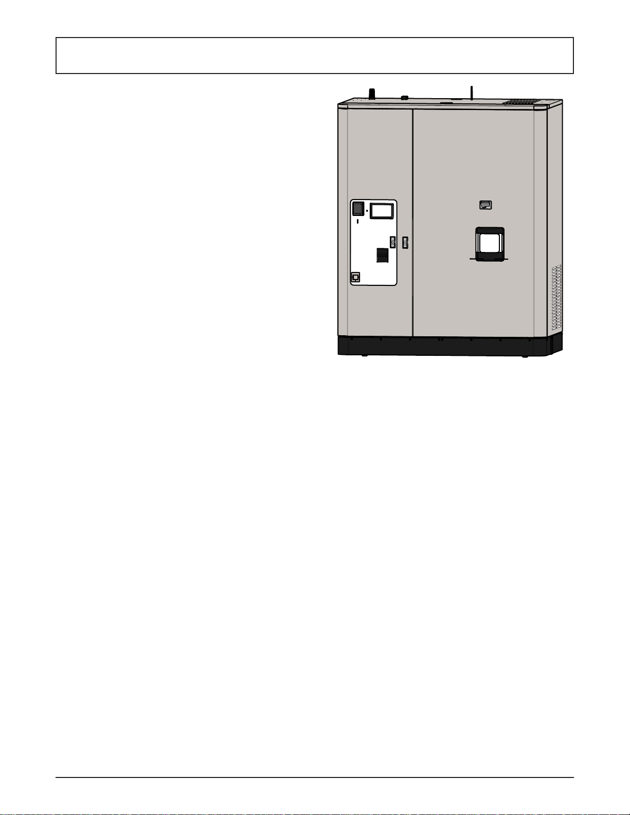
1.1 DESCRIPTION
The Stoelting AUTOVEND machine is a self contained
frozen treat vending machine. The machine takes cash
or credit cards and serves two different fl avors or a twist
along with up to four different toppings.
This manual is designed to assist qualifi ed service per-
sonnel and operators in the installation, operation and
maintenance of the Stoelting AUTOVEND machine.
Figure 1-1 AUTOVEND Machine
Owner’s Manual #513698 Rev.1 1 AUTOVEND Model Machines
Page 8

1.2 SPECIFICATIONS
Model AUTOVEND
Dimensions Machine as shipped
width 66-3/8’’ (168,6 cm) 77’’ (195,6 cm)
height 87-1/4’’ (221,6 cm) 92’’ (233,7 cm)
depth 41-7/8’’ (106,4 cm) 48’’ (121,9 cm)
Weight 1300 lbs (589,6 kg) 2100 lbs (952,5 kg)
Electrical 1 Phase, 208-240 VAC, 60Hz
connection type NEMA L6-30P power cord provided
convenience outlet 1 Phase, 115 VAC, 60Hz
outlet connection type NEMA 5-15P
Compressor 12,000 Btu/hr (R-404A)
Drive Motor Two - 3/4 hp
Air Flow Air cooled units require 6” (15,2 cm) air space on both sides
Hopper Volume Two - 3 gallon (11,35 liters)
Freezing Cylinder
Volume
Topping Bin Four - 9 quart (8,6 liters)
Two - 0.85 gallon (3,22 liters)
Owner’s Manual #513698 Rev.1 2 AUTOVEND Model Machines
Page 9

SECTION 2
INITIAL SET-UP AND OPERATION
2.1 OPERATOR’S SAFETY PRECAUTIONS
SAFE OPERATION IS NO ACCIDENT; observe these
rules:
A. Know the machine. Read and understand the
Operating Instructions.
B. Notice all warning labels on the machine.
C. Wear proper clothing. Avoid loose fi tting garments,
and remove watches, rings or jewelry that could
cause a serious accident.
D. Maintain a clean work area. Avoid accidents by
cleaning up the area and keeping it clean.
E. Stay alert at all times. Know which switch, push
button or control you are about to use and what
effect it is going to have.
F. Disconnect power for maintenance. Never
attempt to repair or perform maintenance on the
machine until the main electrical power has been
disconnected.
G. Do not operate under unsafe operating conditions.
Never operate the machine if unusual or excessive
noise or vibration occurs.
2.2 OPERATING CONTROLS AND INDICATORS
Before operating the machine, it is required that the operator know the function of each operating control. Refer
to Figure 2-1 for the location of the operating controls on
the machine. For the information regarding error codes
displayed on the control panel, refer to the troubleshooting
section of this manual.
WARNING
High voltage will shock, burn or cause death. The
OFF-ON switch must be placed in the OFF position
prior to disassembling for cleaning or servicing. Do
not operate machine with panels removed.
CARD SWIPE READER
The card swipe reader is made by USA Technologies.
An account with USA Technologies is required for it to
operate. The card swipe reader uses cellular towers for
communication and is on a separate network than the
IntelliTec2™.
Vending Interface
Vending Interface
Card Swipe Reader
Card Swipe Reader
Coin Slot
Coin Slot
Pop-Out T-Handle Lock
Pop-Out T-Handle Lock
Bill Acceptor
Bill Acceptor
Change Dispenser
Change Dispenser
Figure 2-1 Machine Controls
Spoon Dispenser
Spoon Dispenser
Dispensing Carousel
Dispensing Carousel
Owner’s Manual #513698 Rev.1 3 AUTOVEND Model Machines
Page 10

A. INTELLITEC2™ TOUCHPAD
Figure 2-3 IntelliTec2™ Control
Figure 2-2 Vending Interface
VENDING INTERFACE
The vending interface is a touch screen used for customer
ordering and technician confi guring. It is also used to
manually open and close the spigots during cleaning.
COIN SLOT
The coin slot accepts nickels, dimes, quarters, and dollar coins.
POP-OUT T-HANDLE LOCK
The machine has two locks which are keyed separately;
one for the main door and one for the vending door.
BILL ACCEPTOR
The bill acceptor can be confi gured to accept any combina-
tion of denominations from $1 to $20. The denomination
settings are changed on the DIP switches located on the
side of the acceptor. Refer to the instructions printed on
the acceptor to change denominations.
NOTE
If the customer inserts more than one bill and
cancels the order, only the last bill inserted will
be returned. The remaining change will be given
in coins. For example: if a customer inserts a $20
then a $1 and then cancels the order, the $1 bill will
be returned along with 20 dollars’ worth of coins.
CHANGE DISPENSER
The change dispenser dispenses change from a sale or
from a canceled order.
SPOON DISPENSER
The spoon dispenser automatically dispenses a spoon
when a product is delivered.
DISPENSING CAROUSEL
The dispensing carousel rotates when a cup of product
is served. The carousel remains open until it senses the
cup has been removed.
The IntelliTec2™ touchpad is located behind the cup
assembly in the machine. The touchpad controls the
machine operation.
NOTE
Adjustments to the dispensing system are done
through the vending interface.
Following is a description of each button on the IntelliTec2™ touchpad.
Main Power On/Off
The Main Power button is used to supply power to the
IntelliTec2 control, the freezing cylinder circuits and the
storage refrigeration system. When the machine is fi rst
plugged in, the control defaults to the On status with power
to the hopper only. If the Main Power On/Off button is
pressed when the machine is on, the machine will turn
off and a status message will be displayed on the screen.
Help
Pressing the Help button will display help information
dependant on the cursor’s location. Pressing the Help
button again will exit the help screen.
Selection Button (SEL)
The SEL button is used by technicians to select menu
options.
Set Button (SET)
The SET button is used by technicians to save changes
when modifying control settings.
On/Off Button
Power to the freezing cylinders can then be controlled
with the On/Off Left and On/Off Right switches.
Push to Freeze Button
Pressing the PUSH TO FREEZE button initiates “Serve
Mode”.
Clean Button
The CLEAN button initiates “Clean Mode”.
Arrow Buttons ()
The arrow buttons are used by technicians to navigate
through the control readings and settings.
Owner’s Manual #513698 Rev.1 4 AUTOVEND Model Machines
Page 11

Main Door Safety Switch
IntelliTec2 Control
IntelliTec2 Control
Cup Assembly
Cup Assembly
Figure 2-4 Internal Machine Assemblies
B. MAIN DOOR SAFETY SWITCH
The main door safety switch is a snap action door interlock switch. When the door is open, there is no power to
the vending system. When the door is shut, or the switch
actuator is pulled outward, the vending system receives
power.
C. CUP ASSEMBLY
The cup assembly has fi ve tubes that hold a maximum of
30 cups each. When refi lling, pull the cups apart before
inserting them into the tube so they are not stuck together.
The assembly dispenses cups until the tube is empty
then automatically rotates counterclockwise to the next
tube. If a tube must be left empty, make sure it is to the
right of the front tube.
D. TOPPING ASSEMBLY
The topping assembly automatically dispenses toppings
based on the customer’s order. The assembly consists
of four bins with covers and the dispensing chutes. When
a customer selects a topping, an auger rotates for a
preselected time.
Be sure the vending interface screen matches the contents
of the topping bins. The bin furthest left includes an agitator for nonuniform sized toppings, such as cookie pieces.
Main Door Safety Switch
Topping Assembly
Topping Assembly
D. Turn off the freezing cylinders by pressing the
On/Off buttons.
E. Press the Clean buttons. Allow the product to
agitate for about 5 minutes.
F . Remove the mix inlet regulators from the hoppers.
G. On the vending interface, press and hold the
screen in the upper left corner until a passcode
screen is displayed.
NOTE
The passcode screen may already be displayed after pulling out the actuator on the door safety switch.
Press Here
Figure 2-5 Accessing Spigot Controls
H. On the passcode screen, enter: 7654. Then press
“ENTER”.
Figure 2-6 Spigot Controls
2.3 EMPTYING THE FREEZING CYLINDER
If the machine is empty, go to Section 2.4.
A. Unlock the T-handle lock on the main door and
open the door.
B. Pull the main door safety switch outwards until it
clicks.
C. On the IntelliTec2™, make sure the Main Freezer
Power is on. If the Current Status Screen is
displayed, then the main power is on.
Owner’s Manual #513698 Rev.1 5 AUTOVEND Model Machines
I. Press “Next” to navigate to the spigot screen.
J. After about 5 minutes press the “Up” buttons to
open the spigots and drain the mix.
NOTE
Press the up button twice to fully open the spigot
K. Press the Clean button on the IntelliTec2™ to
stop the auger and press the “Down” buttons on
the vending interface to close the spigots.
L. Fill the hopper with 2 gallons (8 liters) of cool tap
water.
Page 12

M. Press the Clean button and let the auger rotate
for at least 30 seconds.
N. While the auger is rotating, scrub the hopper with
a clean brush.
O. Drain the water out of the machine.
NOTE
If the water does not drain clear, repeat steps B
through E.
P. Press the Clean button again to stop the auger.
Q. Optional: Fill the hopper with about 2 gallons
of Stera-Sheen solution (prepared following
manufacturers instructions) and follow steps B
through E above.
NOTE
Running the solution through the machine makes
cleaning parts easier after disassembly.
2.4 DISASSEMBLY OF MACHINE PARTS
Before using the machine for the fi rst time, complete
machine disassembly, cleaning, and sanitizing procedures need to be followed. Routine cleaning intervals
and procedures must comply with the local and state
health codes. Inspection for worn or broken parts should
be made at every disassembly of the machine. All worn
or broken parts should be replaced to ensure safety to
both the operator and the customer and to maintain good
machine performance and a quality product. Check the
wear line on the auger fl ights on a regular basis (Fig.
2-7) and replace as needed. Frequency of cleaning must
comply with the local health regulations.
Pull out spigot pinsPull out spigot pins
Figure 2-8 Spigot Pins
2. Pull out the spigot pins.
3. Remove the rosette caps from the bottom of the
front door
4. Remove the knobs on the front door and remove
the front door by pulling it off the studs.
5. Remove the spigots through the bottom of the
front door.
6. Remove all o-rings from parts by fi rst wiping off
the lubricant using a clean towel. Then squeeze
the o-ring upward to form a loop (Fig. 2-9). Roll
the o-ring out of the groove.
Wear Line
Figure 2-9 Removing O-Ring
Figure 2-7 Auger Flight Wear
T o disassemble the machine, refer to the following steps:
A. DISASSEMBLY OF FRONT DOOR
1. On the IntelliTec2™ control, press and hold the
Main Freezer Power button for three seconds to
turn the power off.
Owner’s Manual #513698 Rev.1 6 AUTOVEND Model Machines
B. DISASSEMBLY OF AUGER
1. Remove the front auger supports and bushings.
2. Remove the auger assemblies from the machine.
Pull the augers out of the freezing cylinder slowly .
As the augers are being pulled out, carefully
remove each of the plastic fl ights with springs.
3. Keep the rear of the augers tipped up once they
are clear of the freezing cylinder to prevent the
rear seal assemblies from dropping.
Page 13

Figure 2-10 Rear Seal
4. Wipe lubricant off of the hex end of the augers with
a paper towel. Remove the rear seal assemblies
(Fig. 2-10).
5. Wipe any excess lubricant off the rear seals.
6. Unscrew the springs from the auger fl ights.
C. DISASSEMBLING TOPPING ASSEMBLY
The topping assembly must be disassembled, cleaned and
sanitized prior to use. Frequency of cleaning the topping
assembly must comply with the local health regulations.
Bin Cover
Bin Cover
Tilt to the Right
Tilt to the Right
and Back
and Back
Figure 2-13 Tilt Bin to Remove
3. Tilt the bin to the side and back.
4. Pull bin forward to disengage the motor from the
auger.
5. Each bin has an auger assembly that must be
disassembled for cleaning. Unscrew the ends
and remove the auger.
6. The bin on the far left also has an agitator that must
be removed for cleaning. The agitator consists
of a gear and two springs. To remove, press the
bin ends inwards to bow the sides outward, then
twist the agitator to disengage.
Bin
Bin
Chute Cover
Chute Cover
Chute Cone
Chute Cone
Figure 2-11 Topper Assembly
1. Remove the cones and covers from the topping
chutes.
2. Push the bin backwards so that the pins disengage.
Figure 2-14 Topper Bin Assembly
D. REMOVE TRAYS
The machine has a drip tray and a topping overfl ow that
need to be removed for cleaning.
Drip Tray
Drip Tray
Topping Overflow
Topping Overflow
Push Back to Disengage PinsPush Back to Disengage Pins
Figure 2-12 Disengage Topping Bin Pins
Figure 2-15 Trays
Owner’s Manual #513698 Rev.1 7 AUTOVEND Model Machines
Page 14

2.5 CLEANING DISASSEMBLED PARTS
Disassembled parts require complete cleaning, sanitizing
and air drying before assembling. Local and state health
codes dictate the procedure required. Some state health
codes require a four sink process (pre-wash, wash, rinse,
sanitize, air dry), while others require a three sink process
(without the pre-wash step). The following procedures
are a general guideline only . Consult your local and state
health codes for the procedures required in your location.
A. Disassemble all parts. (Refer to Section 2.4 for
the disassembly of machine parts)
B. Place all parts in 90° to 110°F (32°C to 43°C)
mild detergent water and wash thoroughly. Use
the brushes that shipped with the machine to
clean all holes in the front door, fl ights, mix pickup
assembly, etc.
C. Rinse all parts with clean 90° to 110°F (32°C to
43°C) water.
D. Place all parts in a sanitizing solution for at least
1 minute, then remove and let air dry completely
before assembling in machine.
2.6 CLEANING THE MACHINE
Cleaning the machine includes washing the hoppers,
freezing cylinders, cup assemblies, shadowbox, ramp, and
carousel. T o properly clean the machine, a mild detergent
water, sponges or washcloths, a large brush, and a shop
vac are recommended.
A. CLEANING HOPPER & FREEZING CYLINDER
1. Clean the hoppers with a large brush.
2. Clean the rear seal surfaces on the inside of the
freezing cylinders.
3. Using sanitizing solution and the large barrel
brush provided, sanitize the freezing cylinders by
dipping the brush in the sanitizing solution and
brushing the inside of the freezing cylinders.
4. Wrap the brush in a clean sanitized cloth and
thoroughly dry the freezing cylinders.
B. CLEANING CUP TRANSPORT ASSEMBLIES
1. With the main door open and the power switch
set to the off position (middle position), manually
move the cup assembly so that it can be cleaned.
The assembly will be behind the vending box.
2. Remove the cup shield cover and remove the
cup holder. Do not lose the lock washers when
removing the parts for cleaning.
3. Clean the shield cover and cup holder and clean
the IR sensor.
NOTE
The IR sensor must be cleaned so it can properly
sense when a cup is present.
4. Install the cup holder and shield.
Remove Thumbscrew,
Remove Thumbscrew,
Remove Shield,
Remove Shield,
& Clean
& Clean
Remove Cup Holder
Remove Cup Holder
Thumbscrews &
Thumbscrews &
Clean Cup Holder
Clean Cup Holder
Clean IR Sensors
Clean IR Sensors
Figure 2-16 Cup Assembly
5. Wipe the toppings cup holder clean.
C. CLEANING SHADOWBOX, RAMP , AND CAROUSEL
1. Clean the shadowbox, ramp and carousel.
2. Vacuum the surfaces if any toppings have dropped.
Wipe All Surfaces Clean &
Wipe All Surfaces Clean &
Vacuum Up Toppings
Vacuum Up Toppings
Figure 2-17 Clean Dispensing Assembly
2.7 ASSEMBLING MACHINE
T o assemble the machine parts, refer to the following steps:
NOTICE
Total Blend sanitary lubricant, Petrol-Gel sanitary
lubricant, or equivalent must be used when lubrication of machine parts is specifi ed.
T otal Blend can be used in place of two products. It
is used to lubricate parts and also used in place of
spline lubricant. Do not use more than one packet
of Total Blend per freezing cylinder.
NOTICE
The United States Department of Agriculture and
the Food and Drug Administration require that lubricants used on food processing equipment be certifi ed for this use. Use lubricants only in accordance
with the manufacturer’s instructions.
Owner’s Manual #513698 Rev.1 8 AUTOVEND Model Machines
Page 15

Figure 2-18 Lubricate Rear Seal
A. INSTALLING AUGER
1. Install the rear seal o-rings. Lubricate the outside
of the rear seal o-rings with a generous amount
Total Blend lubricant.
2. Lubricate the inside metal surfaces of the rear
seals (Fig. 2-18) and install them onto the auger
shaft. DO NOT lubricate the outside of the rear
seals.
3. Lubricate the hex drive ends of the auger with a
small amount of Total Blend lubricant.
7. Apply a thin layer of sanitary lubricant to the inside
and outside of the auger support bushings. Install
the bushings onto the auger supports and install
the auger supports into the front of the augers.
Rotate the auger supports so that one leg of the
support points straight up.
B. INSTALLING FRONT DOOR
1. Install the o-rings onto the spigot bodies and apply
a thin layer of sanitary lubricant to the o-rings.
Install the spigot bodies through the bottom of
the front door.
2. Fit the front door o-rings into the grooves on the
rear of the front door.
3. Place the front door assembly on the mounting
studs and the push front door against the machine
carefully.
NOTE
Make sure the pins of the front door do not touch
the legs of the auger support.
4. Secure the front door to the machine by placing
the knobs on the studs and tightening until fi nger
tight. Tighten in a crisscross pattern. Do not
overtighten. Proper o-ring seal can be observed
through the transparent front door.
5. Install the spigot pins through the actuators and
spigots.
6. Install the rosette caps to the bottom of the front
door.
C. INSTALLING TOPPING ASSEMBLY
1. Install the auger assemblies into the topping bins.
Install the agitator into the bin on the far left.
2. Install the canisters into the brackets. When
installing, tilt the canister backwards to engage
the motor shaft, then press downward to lock into
place.
NOTE
The canister with the agitator must be installed
furthest left.
Figure 2-19 Lubricate Auger Spline
4. Screw the springs onto the studs in the plastic
fl ights. The springs must be screwed into the
fl ights completely to provide proper compression.
5. Install the two plastic fl ights onto the rear of the
augers and insert them part way into the freezing
cylinder.
6. Install the remaining plastic fl ights, push the augers
into the freezing cylinders and rotate slowly until
the augers engage the drive shafts.
Owner’s Manual #513698 Rev.1 9 AUTOVEND Model Machines
3. Install the chutes onto the dispense slides.
4. Install the chute cones. Make sure the metal lip
of the chute is inside the cone.
2.8 SANITIZING
Sanitizing must be done after the machine is clean and
just before the machine is fi lled with mix. Sanitizing the
night before is not effective. However , you should always
clean the machine and parts after using it.
NOTE
The United States Department of Agriculture and
the Food and Drug Administration require that all
cleaning and sanitizing solutions used with food
processing equipment be certifi ed for this use.
Page 16

When sanitizing the machine, refer to local sanitary regulations for applicable codes and recommended sanitizing
products and procedures. The frequency of sanitizing
must comply with local health regulations. Mix sanitizer
according to manufacturer’s instructions to provide a 100
parts per million strength solution. Mix sanitizer in quantities of no less than 2 gallons of 90°F to 110°F (32°C to
43°C) water. Allow sanitizer to contact the surfaces to be
sanitized for 5 minutes. Any sanitizer must be used only
in accordance with the manufacturer’s instructions.
A. Prepare 2 gallons of Stera-Sheen sanitizing
solution for each freezing cylinder following the
manufacturer’s instructions.
B. Install the mix inlet regulators into the hoppers
so the bends are towards the right.
C. Install the inserts into the regulators. Turn the
inserts so the fl ow rates are set to the number 3
position.
Set flow rate to the
Set flow rate to the
3 position
3 position
J. On the passcode screen, enter: 7654. Then press
“ENTER”.
K. Press “Next” to navigate to the spigot screen.
L. After about 5 minutes press the “Up” buttons to
open the spigots and drain the mix.
NOTE
Press the open button twice to fully open the spigot
M. On the IntelliT ec2™ touchpad, Press the CLEAN
buttons to stop the augers. Allow the freezing
cylinder to drain completely.
The machine is now sanitized and ready for adding mix.
2.9 FREEZE DOWN AND OPERATION
A. Sanitize immediately before use.
B. Fill each hopper with at least 2.5 gallons of mix.
C. Fill the topping canisters
NOTE
The default settings for toppings are the following:
1. Furthest Left: Oreo
®
Figure 2-20 Mix Inlet Regulator Flow Rate
D. Pour the sanitizing solution into the hoppers.
E. On the IntelliTec2™ control, press the Main
Freezer Power button to turn the power on.
F. Press the CLEAN buttons.
G. Check for leaks at the front door seal.
H. Use a sanitized soft bristle brush dipped in
sanitizing solution to clean the hopper sides, the
mix inlet regulators, and the undersides of the
hopper covers.
I. On the vending interface, press and hold the
screen in the upper left corner until a passcode
screen is displayed.
NOTE
The passcode screen may already be displayed
after pulling out the door safety switch
2. Middle Left: Sprinkled Chocolate Chip
3. Middle Right: Slivered Almonds
4. Furthest Right: M&M’s
®
If changing the topping variety in the bins, make
sure to change the vending interface.
D. Place a container under the spigots and open
the spigots to allow the mix to fl ush out about
8 ounces (0.23 liters) of sanitizing solution and
liquid mix.
E. On the IntelliTec2™ touchpad, press the On/Off
buttons to turn the freezing cylinders On.
F . Allow the freezing cylinders to fi ll. Then press the
PUSH TO FREEZE buttons.
G. When product is ready, the IntelliTec2™ display
reads “SERVE 2”.
NOTE
Make sure the product is ready to serve before allowing customers to place orders.
Owner’s Manual #513698 Rev.1 10 AUTOVEND Model Machines
Page 17

SECTION 3
MAINTENANCE AND ADJUSTMENTS
This section is intended to provide maintenance personnel
with a general understanding of the machine adjustments.
It is recommended that any adjustments be made by a
qualifi ed person.
3.1 FINE CONSISTENCY ADJUSTMENT
If the product consistency needs to be adjusted, use the
Fine Consistency Adjustment. To access the setting, the
Associate level password must be entered. Follow the
steps below for the Fine Consistency Adjustment.
A. Press the left arrow from the Current Status
screen.
B. Press the right arrow then the SEL button from
the Password screen. After the password is
accepted, move the cursor to the Fine Consistency
Adjustment option and press the SEL button.
C. On the Fine Consistency Adjustment screen, press
the SET button and use the arrows to modify the
setting. Adjust the Fine Consistency higher to
increase the consistency or lower to decrease
the consistency. Press the SEL button to toggle
between left and right freezing cylinders.
D. Press the SET button to save the changes. Make
adjustments in increments of 5 for best results.
3.2 DRIVE BELT TENSION ADJUSTMENT
To check belt tension, refer to Figure 4-1 and follow the
steps below:
A. Remove the back right panel.
B. Use a Burroughs Belt Tension Gauge to set the
tension for the drive belt. Set the belt tension to
50-55 lbs.
C. If an adjustment is necessary, adjust belt tension
bolt.
D. Using a straightedge, check that the drive motor
pulley is aligned with the speed reducer pulley.
Align the pulley if necessary.
NOTE
Belt life will be increased if new drive belts are
tightened after two or three weeks of operation.
3.3 CONDENSER CLEANING (AIR-COOLED
MACHINES)
The condenser requires periodic cleaning. T o clean, refer
to the following procedures.
A. Disconnect power to the machine.
B. Remove the right side panel.
C. T o remove the condenser fi lter, grasp the top and
pull off. Visually inspect the fi lter for dirt. If it is
dirty , shake or brush excess dirt off of it and wash
it in warm, soapy water. Once the fi lter is clean,
rinse it thoroughly in warm, clear water and shake
dry, taking care not to damage it in any way.
NOTE
If the condenser is not kept clean, refrigeration effi ciency will be lost.
3.4 COIN CHANGER MAINTENANCE
The coin changer attempts to maintain a certain quantity
of coins in the coin tubes. This quantity is called the "fl oat"
(also known as PAR setting). The ideal fl oat is to have
just enough coins needed to provide change to every
customer between maintenance visits.
FLOAT OPERATION
During maintenance, use the fl oat operation to dispense or
insert coins to bring the coin level to the fl oat setting. The
factory default fl oat setting is full tubes (the fl oat operation
will request coins to be inserted until each coin tube is full)
NOTE
Refer to the MEI Cashfl ow operation guide for in-
formation on how to change the fl oat value.
A. Press the yellow button on the coin manager to
access the menu.
B. Press the A button to select FLOAT
C. After two seconds, the changer dispenses any
excess coins.
D. If a coin tube is low , the display shows the quantity
needed to achieve the fl oat value. Add coins or
press Skip.
E. Press the Finish button.
Owner’s Manual #513698 Rev.1 11 AUTOVEND Model Machines
Page 18

3.5 BILL ACCEPTOR
The bill acceptor has the following confi guration options:
• Bill Direction
• High Acceptance or High Security
• Denominations
The settings are changed on the DIP switches located on
the side of the acceptor. Refer to the instructions printed on
the side of the acceptor to change confi guration options.
3.6 SPOON DISPENSER
The spoon dispenser requires Dixie SmartStock spoons
to operate.
ADDING SPOONS
1. Loosen the knob holding the spoon dispenser to
the door and slide the knob to the right.
2. Rotate the spoon dispenser to access the front
of the unit.
3. Open the top cover of the dispenser and fi ll with
Dixie SmartStock spoons.
NOTE
After fi lling, make sure the clear window at the front
of the dispenser is closed.
4. Rotate the spoon dispenser back into place, slide
the knob to the left, and tighten the knob. Make
sure the washer is between the knob and the
metal bracket.
3.7 PREVENTATIVE MAINTENANCE
It is recommended that a preventative maintenance
schedule be followed to keep the machine clean and
operating properly . The following steps are suggested as
a preventative maintenance guide.
A. Daily checks
Check for any unusual noise or condition and
repair immediately.
T opping Assemblies - Remove chutes and inspect
for blockages.
Splash Panels & Trays - Wipe splash panels and
remove and clean trays.
Cup Holders - Wipe cup holder and splash shields.
Carousel Door - Remove any spilled toppings
and wipe clean.
Mix Hopper - Remove any foam accumulation in
the hoppers.
Mix Inlet Regulator - Some products may require
the mix inlet regulator be removed and cleaned.
B. Monthly checks
Check the condenser for dirt and clean if
necessary.
C. Quarterly Checks
Check drive belts for wear and tighten belts if
necessary.
3.8 EXTENDED STORAGE
Refer to the following steps for storage of the machine
over any long period of shutdown time:
A. Clean all the parts that come in contact with mix
thoroughly with a warm detergent water. Rinse
in clear water and dry all parts. Do not sanitize.
NOTE
Do not let cleaning solution stand in the freezing
cylinder or hopper during the shutdown period.
B. Remove, disassemble, and clean the front door,
and auger shaft. Leave disassembled during the
shutdown period.
C. Place the auger fl ights and auger support bushing
in a plastic bag with a moist paper towel. This will
prevent them from becoming brittle if exposed to
dry air over an extended period of time (over 30
days).
D. Press the Main Power On/Off button to turn the
machine off.
E. Disconnect the machine from the source of
electrical supply.
Owner’s Manual #513698 Rev.1 12 AUTOVEND Model Machines
Page 19

SECTION 4
TROUBLESHOOTING
4.1 OUT OF ORDER
If the vending interface shows an out of order screen,
complete the following checks before contacting a service
technician.
CUP LEVELS
Make sure there is a minimum of three tubes full of cups.
Insert a maximum of 30 cups into each tube. When inserting, pull them apart slightly so they are not stuck together.
Discard any damaged cups.
MIX LEVELS
Make sure the hoppers are at least 3/4 full of liquid mix.
Add mix if necessary.
CAROUSEL DOOR
Make sure there are no objects in the carousel door and
remove them if necessary.
CUP HOLDER ASSEMBLIES
Make sure the thumb screws on the cup holder assemblies
are tight. Tighten as necessary.
INTELLITEC2™ ERROR
Refer to Section 4.2 for troubleshooting error codes on
the IntelliTec2™ control.
4.2 INTELLITEC2™ ERROR CODES
When the machine experiences a problem, one of the
following error codes will be displayed on the control
panel. Each error code directs you to the system location
of the malfunction.
ERROR CODE MALFUNCTION
2 High Torque
3 Run Time
4 Clean
5 Freezing Cylinder Sensor
6 Hopper Sensor (single hopper machines)
7 Drive Motor
8 Cab Sensor
9 High Pressure Cutout
10 Auxiliary Sensor
11 Prime (cab units only)
12 Left Hopper Sensor
13 Right Hopper Sensor
21 Spigot Open Time
To return the machine to normal operation, any error
causing condition must be corrected and the power to
the affected freezing cylinder must be cycled. Turn the
power to the freezing cylinder off then back on using the
On/Off button of the affected freezing cylinder.
4.3 INTELLITEC2™ ERROR CODE
TROUBLESHOOTING
Error Code 2 - High Torque
If the control panel displays a High Torque Error
(E2), the controller has sensed that the drive motor
is running at a high load for 10 or more seconds.
This may be due to the product consistency
adjustment being set too high. Press the On/Off
button for the cylinder to turn it off, wait until the
product in the freezing cylinder thaws and then
turn the cylinder back on. If the error persists,
contact your Authorized Stoelting Distributor for
further assistance.
Error Code 3 - Run Time
The Run Time Error (E3) occurs when the
compressor runs continuously for an extended
period. This error is generally caused by very
low mix levels in the hopper or from product
breakdown. Another common cause results from
a restriction preventing mix from entering the
freezing cylinder. Check the mix in the hopper.
If the level mix is low, add mix. If there is a
possibility that the mix has broken down, clean
and sanitize the machine and replace the mix
with fresh product.
Ice crystals in the hopper can clog the mix inlet
system and prevent mix from entering the freezing
cylinder. Thoroughly thaw mix per manufacturer’s
recommendations. T o check for ice crystals, pour
a small amount of product from the mix container
through a clean and sanitized sieve or strainer.
If ice crystals are in the mix, check temperature
of the walk-in cooler where the mix is stored.
In air cooled machines, the Run Time Error
may indicate that airfl ow within the machine
has reduced or stopped. Check the sides of the
machine for anything that would restrict airfl ow.
If the error persists after attempting to clear it,
contact your Authorized Stoelting Distributor for
further assistance.
Error Code 4 - Clean
If the machine is left in the Clean Mode for more
than 20 minutes, the control panel will display a
Clean Error (E4). This condition does not refl ect a
problem with the machine itself. The Clean Error
has been programmed into the controller as a
safeguard to protect the machine from potential
damage caused by the machine being accidentally
left in "Clean Mode". To clear the Clean Error,
press the On/Off button for the cylinder to turn if
off then back on.
Owner’s Manual #513698 Rev.1 13 AUTOVEND Model Machines
Page 20

Error Code 5 - Freezing Cylinder Sensor
The Freezing Cylinder Sensor Error (E5) indicates
a failure of the barrel sensor or if the sensor is
out of range. If the control panel displays an E5,
press the On/Off button for the cylinder to turn
if off then back on. If the error persists, contact
your Authorized Stoelting Distributor for further
assistance.
NOTE
When the machine encounters a Freezing Cylinder
Sensor Error, the machine will continue to run using
preset timers. This mode will allow the operator to
continue serving product until the machine can be
serviced.
Error Code 7 - Drive Motor
If the control panel displays a Drive Motor Error
(E7), the control does not sense current coming
from the drive motor. Press the On/Off button
for the cylinder to turn if off then back on. If the
error persists, contact your Authorized Stoelting
Distributor for further assistance.
Error Code 8 - Cab Sensor
A Cab Sensor Error (E8) will not occur on the
machine.
Error Code 9 - High Pressure Cutout
High Pressure Cutout Errors (E9) are usually
caused by a dirty or ineffi cient condenser. If the
control panel displays an E9 on an air cooled
machine, check for proper air clearance around
the machine.
If the error persists, contact your Authorized
Stoelting Distributor for further assistance.
Error Code 10 - Auxiliary Sensor
An Auxiliary Temperature Sensor Error (E10)
occurs if the temperature sensor on the control
board fails. Press the On/Off button for the cylinder
to turn if off then back on. If the error persists,
contact your Authorized Stoelting Distributor for
further assistance
Error Code 12 - Left Hopper Sensor
The Left Hopper Sensor Error (E12) indicates
a failure of the hopper sensor or if the sensor is
out of range. If the control panel displays an E12,
press the On/Off button for the cylinder to turn
if off then back on. If the error persists, contact
your Authorized Stoelting Distributor for further
assistance.
Error Code 13 - Right Hopper Sensor
The Right Hopper Sensor Error (E13) indicates
a failure of the hopper sensor or if the sensor is
out of range. If the control panel displays an E12,
press the On/Off button for the cylinder to turn
if off then back on. If the error persists, contact
your Authorized Stoelting Distributor for further
assistance.
Error Code 21 - Spigot Open Time
The Spigot Open Time Error (E21) indicates a
failure of the spigot switch. If the control senses
the spigot is open continuously for 10 minutes, the
machine will go into Sleep 3 mode. If the control
panel displays an E21, press the On/Off button
for the cylinder to turn if off then back on. If the
error persists, contact your Authorized Stoelting
Distributor for further assistance.
Owner’s Manual #513698 Rev.1 14 AUTOVEND Model Machines
Page 21

4.3 TROUBLESHOOTING - MACHINE
PROBLEM POSSIBLE CAUSE REMEDY
Machine does not
run.
Machine will not
shut off.
Product is too fi rm.
Product is too soft.
Product does not
dispense.
Drive belt slipping
or squealing.
Rear auger seal
leaks.
Front door leaks.
1 Power to machine is off. 1 Supply power to machine.
2 Freeze-up (auger will not turn). 2 Turn machine off for 15 minutes, then restart.
3 Front door not in place. 3 Assemble front door in place.
1 Refrigeration problem. 1 Check system. (Call distributor for service)
1 CutOut Consistency setting too high 1 Adjust the CutOut Consistency (See Section 3)
1 No vent space for free fl ow of cooling
air.
2 Condenser is dirty. 2 Clean the condenser. (See Section 4)
3 CutOut Consistency setting too low 3 Adjust the CutOut Consistency (See Section 3)
4 Auger is assembled incorrectly. 4 Remove mix, clean, reassemble, sanitize and
5 Refrigeration problem. 5 Check system. (Call distributor for service)
1 No mix in hopper. 1 Add mix to the hopper.
2 Drive motor overload tripped. 2 Wait for automatic reset. (If condition
3 Drive belt failure. 3 Replace drive belt.
4 Freeze-up (Auger will not turn). 4 Turn off cylinder, wait for 15 minutes, then
1 Worn drive belt. 1 Replace drive belt.
2 Freeze-up (Auger will not turn). 2 Turn off cylinder, wait for 15 minutes, then
3 Not tensioned properly. 3 Adjust belt tension
1 Outside surface of rear auger seal is
lubricated.
2 Rear seal missing or damaged. 2 Check or replace.
3 Seal o-ring missing, damaged or
installed incorrectly.
4 Worn or scratched auger shaft. 4 Replace auger shaft.
1 Front door knobs are loose. 1 Tighten knobs.
2 Spigot parts are not lubricated. 2 See Section 3.
3 Chipped or worn spigot o-rings. 3 Replace o-rings.
4 O-rings or spigot installed wrong. 4 Remove spigot and check o-ring.
5 Inner spigot hole in front door nicked
or scratched.
1 A minimum of 3” of air space on the sides.
(See Section 2)
freeze down.
continues, call distributor for service.)
restart.
restart.
1 Clean lubricant from outside of rear seal and
thoroughly clean rear of freezing cylinder.
Lubricate inside of seal and reinstall.
3 Check or replace.
5 Replace front door.
Owner’s Manual #513698 Rev.1 15 AUTOVEND Model Machines
Page 22

Owner’s Manual #513698 Rev.1 16 AUTOVEND Model Machines
Page 23

5.1 DECALS AND LUBRICATION
Part Description Quantity
208135 Brush - 4” X 8” X 16” (Barrel) 1
208380 Brush - 1/4” X 3” X 14” 1
208401 Brush - 1” X 3” X 10” 1
208467 Brush - 3/8” X 1” X 5” 1
236059 Card - Cleaning Instruction 1
324103 Decal - Caution Rotating Shaft 1
324105 Decal - Caution Electrical Shock 1
324106 Decal - Caution Electrical Wiring Materials 1
324107 Decal - Caution Hazardous Moving Parts 1
324125 Decal - Danger Electric Shock Hazard 1
324141 Decal - Caution Rotating Blades 1
324208 Decal - Attention Refrigerant Leak Check 1
324509 Decal - Cleaning Instructions 1
324566 Decal - Wired According To 1
324584 Decal - Adequate Ventilation 3” 3
324594 Decal - Attention Heat Sensitive 4
324672 Decal - Not Packing Material 1
324686 Decal - Danger Automatic Start 1
324803 Decal - Domed Stoelting Logo (Large) (Header Panel) 1
508048 Lubricant - Spline (2 oz Squeeze Tube) 1
508135 Petrol Gel - 4 oz Tube 1
SECTION 5
REPLACEMENT PARTS
Owner’s Manual #513698 Rev.1 17 AUTOVEND Model Machines
Page 24

5.2 AUGER SHAFT AND FACEPLATE PARTS
381804
381804
482019
482019
149003
149003
2177428
2177428
2205440
2205440
2204242
2204242
625133
625133
2204095
2204095
694255
694255
4157968
4157968
666786
666786
624678
624678
624664
624664
2204096
2204096
624614
624614
Part Description Quantity
149003 Bushing - Front Auger Support 2
381804 Auger Flight 10
482019 Knob - Front Door (Black) 4
624598-5 O-Ring - Outside Spigot - Black (5 Pack) 4
624614-5 O-Ring - Top & Bottom Center Spigot - Black (5 Pack) 2
624664-5 O-Ring - Middle Center Spigot - Black (5 Pack) 1
624678-5 O-Ring - Rear Seal - Black (5 Pack) 2
625133 O-Ring - Front Door - Red 2
666786 Seal - Rear Auger - Black 2
694255 Spring - Auger Flight 8
2177428 Door w/Pins 1
2204095 Spigot Body - Outer 2
2204096 Spigot Body - Center 1
2204242 Pin - Spigot 3
2205440 Support - Front Auger 2
4157968 Auger Shaft 2
624598
624598
Owner’s Manual #513698 Rev.1 18 AUTOVEND Model Machines
Page 25

5.3 TRAYS, BINS & HOPPER PARTS
314453
314453
2205992
2205992
2203352
2203352
624677
744614
744614
624677
230035
230035
230030
230030
90039003
558109
558109
230033
230033
230038
230038
93039303
Part Description Quantity
9003 Tray - Topping Overfl ow 1
9303 Tray - Drip 1
230030 Topping Bin - Right w/Agitator 1
230033 Topping Bin - Left 2
230035 Topping Bin - Right 1
230038 Topping Bin - Left w/Agitator *
314453 Cover - Hopper 2
624677 O-Ring - Mix Inlet Regulator 4
744614 Tray - Drain 1
2203352 Mix Inlet Regulator 2
2205992 Cover - Cup Tubes 1
Owner’s Manual #513698 Rev.1 19 AUTOVEND Model Machines
 Loading...