

Page 1

OPTIMA 111
OWNER'S MANUAL
Manual No. 513588R1 Nov. 2004
Page 2

Page 3
Need Part s or Service?
We stock the parts you need.
Our Technicians are factory
trained and are certified in the
Stoelting Technicare program.
CALL
Distributor: _________________________
Phone No.: _________________________
(fill in or affix label)
Model No.: _______________________
Serial No.: _______________________
Purchase Date: ____________________
Start-Up Date:____________________
Page 4

Page 5

OWNER'S MANUAL
FOR
MODEL OPTIMA - STOELTING SOFT SERVE
COUNTER MODEL GRAVITY FREEZER
This manual provides basic information about the freezer. Instructions and suggestions are given
covering its operation and care.
The illustrations and specifications are not binding in detail. We reserve the right to make changes
to the freezer without notice, and without incurring any obligation to modify or provide new parts for
freezers built prior to date of change.
DO NOT ATTEMPT to operate the freezer until instructions and safety precautions in this manual are
read completely and are thoroughly understood. If problems develop or questions arise in connection
with installation, operation or servicing of the freezer, contact the company at the following location.
STOELTING, LLC Tele: 920-894-2293
502 Hwy 67
Kiel, WI 53042-1600 Fax: 920-894-7029
Page 6

Page 7

TABLE OF CONTENTS
SECTION DESCRIPTION PAGE
1. INTRODUCTION
1.1 Description............................................................................................................. 1
1.2 Specifications ........................................................................................................ 1
2. INSTALLATION INSTRUCTIONS
2.1 Safety Precautions ................................................................................................. 3
2.2 Shipment and Transit.............................................................................................. 4
2.3 Freezer Installation ................................................................................................. 4
2.4 Floor Stand Installation ........................................................................................... 5
2.5 Installing Permanent Wiring .................................................................................... 5
3. INITIAL SET-UP AND OPERATION
3.1 Operator's Safety Precautions................................................................................ 7
3.2 Operating Controls and Indicators........................................................................... 7
3.3 Sanitizing ............................................................................................................... 8
3.4 Freeze Down and Operation................................................................................... 9
3.5 Mix Information ....................................................................................................... 10
3.6 Removing Mix From Freezer .................................................................................. 10
3.7 Cleaning The Freezer............................................................................................. 11
3.8 Disassembly of Freezer Parts ................................................................................ 11
3.9 Cleaning The Freezer Parts.................................................................................... 12
3.10 Sanitize Freezer and Freezer Parts....................................................................... 12
3.11 Assembly of Freezer ............................................................................................. 12
3.12 Routine Cleaning................................................................................................... 13
3.13 Preventive Maintenance ........................................................................................ 14
3.14 Extended Storage ................................................................................................. 16
4. TROUBLESHOOTING CHARTS................................................................................ 17
5. REPLACEMENT PARTS ........................................................................................... 21
Page 8

LIST OF ILLUSTRATIONS
FIGURE TITLE PAGE
1 Model Optima 111 Freezer .................................................................................... 1
2 Specifications ........................................................................................................ 1
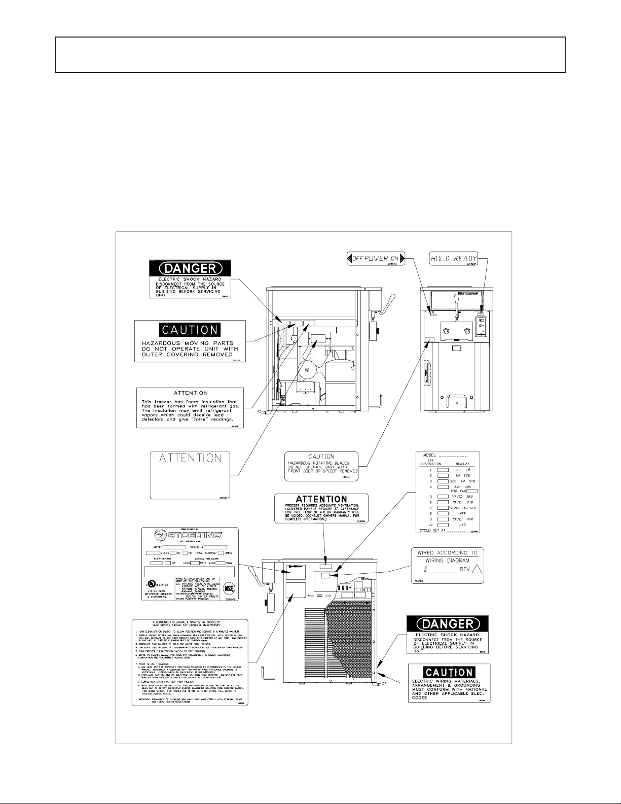
3 Warning Label Locations ....................................................................................... 3
4 Leveling ................................................................................................................. 4
5 Space and Ventilation Requirements ..................................................................... 4
6 Electrical Plug ....................................................................................................... 4
7 Installing Tray and Cover ........................................................................................ 4
8 Floor Stand............................................................................................................ 5
9 Power Cord Connection ......................................................................................... 5
10 Controls ................................................................................................................. 7
11 Mix Inlet Regulator................................................................................................. 9
12 Clean Control......................................................................................................... 9
13 Sanitizing Hopper .................................................................................................. 9
14 Draining Solution ................................................................................................... 9
15 Dispensing Product ...............................................................................................10
16 Removing Mix Inlet Regulator.................................................................................10
17 Draining Mix ..........................................................................................................10
18 Auger Flight Wear & Front Auger Support Bushing Wear.......................................11
19 Removing Front Door ............................................................................................. 11
20 Front Door Disassembly ........................................................................................11
21 Removing Auger Support .......................................................................................11
22 Auger Shaft Removal .............................................................................................12
23 Removing "O" Ring ................................................................................................12
24 Cleaning Freezer Barrel .........................................................................................12
25 Exploded View of Auger.........................................................................................13
26 Exploded View of Front Door.................................................................................. 13
27 Mix Inlet Regulator.................................................................................................13
Page 9

SECTION 1
DESCRIPTION AND SPECIFICATIONS
1.1 DESCRIPTION
The Stoelting Optima 111 counter freezer is gravity fed.
The freezer is equipped with fully automatic controls to
provide a uniform product. The freezer is designed to
operate with almost any type of commercial soft serve or
non-dairy mixer available, including ice milk, ice cream,
yogurt, and frozen dietary desserts. This manual is
designed to assist qualified service personnel and operators in the installation, operation and maintenance of the
Stoelting Model Optima 1 1 1 gravity freezer .
1.2 SPECIFICATIONS
Figure 1. Model Optima 111 Freezer
Figure 2. Specifications
1
FRONT VIEWSIDE VIEW
Page 10

MODEL OPTIMA 1 1 1
COUNTER MODEL
GRA VITY FREEZER
DIMENSIONS:
Freezer: 19-1 1/16" (50 cm) wide x 31-5/8" (80.3 cm) deep x 37-7/16" (95 cm) high
Crated: 28-3/4" (73 cm) wide x 38-3/4" (98.4 cm) deep x 43" (109.2 cm) high
WEIGHT:
Freezer: 310 lbs. (140.6 kg) Crated: 400 lbs. (181.4 kg)
ELECTRICAL:
Description O111
Voltage AC 1 PH 208/230
Total Run Amps 12.70
Drive Motor 2 HP
Use 20 amp HACR circuit breaker .
Automatic safeguard circuit built into electronic control-protects major
freezer components under abnormal operating conditions.
COOLING:
Air cooled, self-contained
Right to left air flow
HFC friendly refrigerant
HOPPER SIZE:
6.5 gallons (24.6 liters)
BARREL SIZE:
1 gallon (3.8 liters)
2
Page 11
SECTION 2
INSTALLATION INSTRUCTIONS
2.1 SAFETY PRECAUTIONS
Do not attempt to operate the freezer until the safety
precautions and operating instructions in this manual are
read completely and are thoroughly understood.
Take notice of all warning labels on the freezer. The labels
have been put there to help maintain a safe working
environment. The labels have been designed to withstand
washing and cleaning. All labels must remain legible for
the life of the freezer. Labels should be checked periodically to be sure they can be recognized as warning labels.
If danger, warning or caution labels are needed, indicate
the part number, type of label, location of label, and
quantity required along with your address and mail to:
STOELTING, INC.
ATTENTION: Customer Service -
Commercial Products Division
502 Hwy. 67
Kiel, Wisconsin 53042
HEAT SENSITIVE THERMISTOR LOCATED
UNDER THIS COVER. TEMPERATUR E
MUST NOT EXCEED 220°F NEAR
THERMISTOR. HEAT SINK MUST BE
USED WHEN BRAZING ON EVAPORATOR
OUTLET. CHECK RESISTANCE BEFORE
REMOVAL OF THERMISTOR.
SEE SERVICE MANUAL.
Figure 3. Warning Label Locations
3
Page 12
2.2 SHIPMENT AND TRANSIT
The freezer has been assembled, operated and inspected
at the factory. Upon arrival at the final destination, the
complete freezer must be checked for any damage which
may have occurred during transit.
With the method of packaging used, the freezer should
arrive in excellent condition. THE CARRIER IS RESPONSIBLE FOR ALL DAMAGE IN TRANSIT, WHETHER
VISIBLE OR CONCEALED. Do not pay the freight bill until
the freezer has been checked for damage. Have the carrier
note any visible damage on the freight bill. If concealed
damage and/or shortage is found later, advise the carrier
within 10 days and request inspection. The customer must
place claim for damages and/or shortages in shipment
with the carrier. Stoelting, Inc. cannot make any claims
against the carrier.
2.3 FREEZER INSTALLATION
Installation of the freezer involves moving the freezer close
to its permanent location, removing all crating, setting in
place, assembling parts, and cleaning.
A. Uncrate the freezer.
B. Accurate leveling is necessary for correct drainage of
freezer barrel and to insure correct overrun. Place a
spirit level on top of the freezer at each corner to
check for level condition. If adjustment is necessary,
level the freezer by turning the bottom part of each leg
in or out. Then separate freezer base gasket and
install with seam to the back and angle to the top. (Fig.
4).
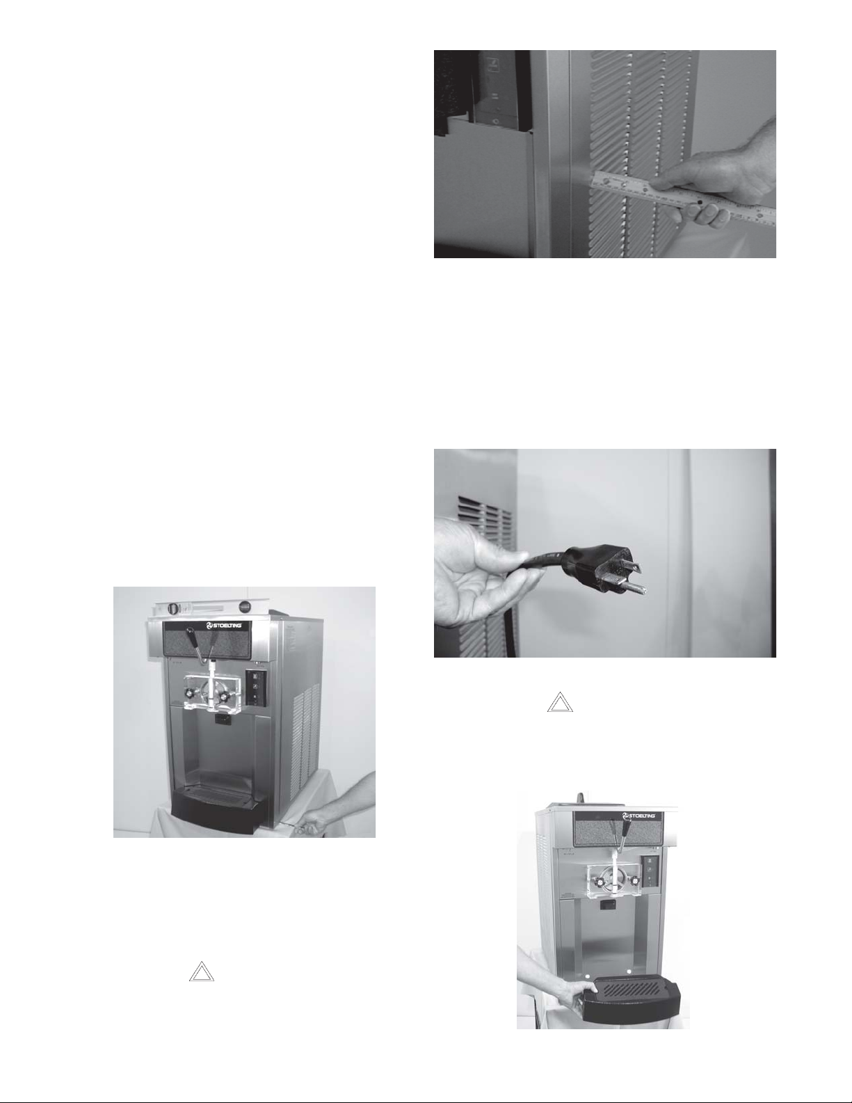
Figure 5. Space and Ventilation Requirements
E. Connect the power cord. The plug is designed for 208
or 230 volt/20 amp duty. Check the nameplate on your
freezer for proper supply. The unit must be connected
to a properly grounded receptacle. The electrical cord
furnished as part of the freezer has a three prong
grounding type plug (Fig. 6). The use of an extension
cord is not recommended, if necessary use one with
a size 12 gauge or heavier with ground wire. Do not use
an adapter to get around grounding requirement.
Figure 4 - Leveling
C. The freezer is equipped with an air cooled condenser
and requires correct ventilation. The right side of the
freezer is the air intake and left side discharge. Both
sides must have 3" clearance. The top requires 10" of
clearance. (Fig. 5).
CAUTION
FAILURE T O PROVIDE ADEQUA TE VENTILA TION
WILL VOID WARRANTY!
D. Place the OFF-ON switch in the OFF position. (Fig.10).
Figure 6. Electrical Plug
CAUTION
DO NOT ALTER OR DEFORM PLUG IN ANY WAY!
F. Install the drip tray, drain tray, hopper cover and other
miscellaneous parts on the freezer. (Fig. 7).
Figure 7. Installing Tray and Cover
4
Page 13

2.4 FLOOR ST AND INST ALLA TION
2.5 INSTALLING PERMANENT WIRING
To install the 0111 onto the floor stand, follow the steps
outlined below:
A. Uncrate the floor stand and place in an upright posi-
tion.
NOTE
Detailed instructions are included with each floor
stand.
B. Place a spirit level across the top of the stand to check
for level condition, side to side and front to back. If
adjustment is necessary , level the stand by turning
the bottom part of each caster in or out, then tighten
the lock nut.
C. Place supports under freezer , then remove the 4 legs
and replace with the rubber stud/plate mounts provided. Mounts must be fully tightened to the freezer .
D. Place the freezer base gasket on the floor stand with
the connected seam to the back and angle side up.
Center the gasket side to side and 1-3/4 inches from
the rear of the floor stand.
E. Place the freezer on the floor stand with the front of
the freezer to the door end. All 4 stud/plate mounts
must engage the holes in the floor stand. Secure the
mounts with the nuts and washers provided. (Fig. 8).
If permanent wiring is required by local codes, the following procedure must be performed.
WARNING
DISCONNECT FREEZER FROM THE SOURCE
OF ELECTRICAL SUPPL Y BEFORE SERVICING.
A. Remove the right side panel.
B. Disconnect the wires from the terminal
block. Disconnect the green ground wire from the
grounding stud. (Fig. 9).
Figure 9. Power Cord Connection
C. Remove the power cord.
D. Install permanent wiring according to local code.
E. Replace the side panel.
Figure 8 - Floor Stand
5
Page 14

6
Page 15

SECTION 3
INITIAL SETUP AND OPERATION
3.1 OPERATOR'S SAFETY PRECAUTIONS
SAFE OPERA TION IS NO ACCIDENT; Observe these
rules:
A. Know the freezer. Read and underst and the
Operating Instructions.
B. Notice all warning labels on the freezer.
C. Wear proper clothing. Avoid loose fitting gar-
ments, and remove watches, rings or jewelry which
could cause a serious accident.
D. Maintain a clean work area. Avoid accidents by
cleaning up the area and keeping it clean.
E. Stay alert at all times. Know which switch, push
button or control you are about to use and what
effect it is going to have.
F. Disconnect electrical cord for maintenance.
Never attempt to repair or perform maintenance on
the freezer until the main electrical power has been
disconnected.
G. Do not operate under unsafe operating condi-
tions. Never operate the freezer if unusual or exces-
sive noise or vibration occurs.
3.2 OPERATING CONTROLS AND INDICATORS
Before operating the freezer, it is required that the
operator know the function of each operating control.
Refer to Figure 10 for the location of the operating
controls on the freezer. For the information regarding
flashing indicator lights, refer to the troubleshooting
section.
WARNING
THE OFF-ON SWITCH MUST BE PLACED IN THE OFF
POSITION WHEN DISASSEMBLING FOR CLEANING
OR SERVICING. THE FREEZER MUST BE DISCONNECTED FROM ELECTRICAL SUPPLY BEFORE REMOVING ANY ACCESS PANEL.
A. SPIGOT SWITCH
The SPIGOT switch will automatically actuate the
auger drive and refrigeration systems when the spigot
is opened to dispense product. When the spigot is
closed, the drive motor and compressor will remain
"on" until the product in the barrel reaches the proper
consistency, or temperature.
High Pressure Cutout
Switch Located Back of
Freezer
(Some Models)
OFF-ON
POWER SWITCH
FRONT DOOR
INTERLOCK
SWITCH
SPIGOT SWITCH
(Behind Panel)
DISPENSE RATE
ADJUSTER
CONSISTENCY/TEMPERATURE
ADJUSTMENT
HOLD READY
SWITCH
PUSH TO FREEZE
CLEAN
MIX LOW
Figure 10. Controls
7
Page 16

B. OFF-ON SWITCH
The OFF-ON switch is a two position toggle switch
used to supply power to the control circuit. When the
switch is in the OFF position, nothing will run. When
the switch is in the ON position the freezer will be in
the idle mode until a switch is activated.
C. PUSH TO FREEZE SWITCH
The PUSH TO FREEZE switch is a "snap" switch used
to start the freezing cycle. During initial freeze down,
the OFF-ON switch is placed in the ON position. Then
the PUSH TO FREEZE switch is pressed until the
drive motor and compressor come "ON".
NOTE
After the gearmotor starts, there is a 3 second delay before the compressor starts.
During the normal operation, the red PUSH TO FREEZE
switch light will illuminate after the freezer has been
idle for the preset cycles. Before drawing product,
press the PUSH TO FREEZE switch if it is illuminated.
Wait until the green light is illuminated before dispensing.
NOTE
If the freezer shuts off and the PUSH TO FREEZE
light flashes, you have an error condition. Turn the
OFF-ON swtich to the OFF position, correct the
problem and turn the freezer back on. (See Troubleshooting.)
D. GREEN LIGHT
The green light is used to indicate that the product has
reached the proper consistency or temperature and is
ready to be dispensed.
G. RED MIX LOW LENS
The red MIX LOW light is designed to alert the operator
to a low mix condition. The lens will illuminate with
approximately one gallon of mix in the hopper. When
the MIX LOW lens is lit, refill hopper immediately.
NOTE
Failure to refill hopper immediately may result in
operational problems. Skim excess foam with a
sanitized utensil. Failure to skim foam can affect
low mix light operation.
H. HOLD READY SWITCH
The HOLD READY switch is a push button switch.
When pushed in and held for 5 seconds, the hold ready
mode will be activated and the word HOLD will illuminate on the touch pad. The product will remain ready
to serve and the freezer will not go to idle. To return to
normal operation push and hold for 5 seconds.
I. DISPENSE RATE ADJUSTERS
The dispense rate adjuster limits the opening of the
spigot. To adjust product dispense rate, turn the
adjusting knob clockwise for slower flow and counterclockwise for faster flow.
J. FRONT DOOR INTERLOCK SWITCH
When the door is securely fastened, the freezer will
operate normally. When the front door is removed, the
drive and compressor will not run.
3.3 SANITIZING
Sanitizing must be done after the freezer is cleaned and
just before the hopper is filled with mix. Sanitizing the night
before is not effective. However, you should always clean
the freezer and parts after using it.
NOTE
If the PUSH TO FREEZE red light is illuminated,
push the PUSH TO FREEZE switch and wait until
the green light illuminates before dispensing.
E. CLEAN SWITCH
The CLEAN switch is a "snap" switch. When the
switch is pushed the refrigeration system will be OFF
and the auger will rotate for cleaning. When the switch
is pushed again, the auger will stop and the CLEAN
light will flash indicating the freezer is in the CLEAN
mode. To exit the CLEAN mode turn the OFF-ON
switch to the OFF position. If the freezer is left in
CLEAN for more than 20 minutes or is pushed three
times in ten seconds, it will go in error. To reset place
the CLEAN-OFF-ON switch in the ON position and
allow the error light to flash a minimum of 10 minutes.
Then turn to off, wait 5 seconds and turn on.
F. DRIVE MOTOR OVERLOAD
The internal DRIVE MOTOR OVERLOAD will trip if the
drive motor is overloaded. It will reset after approximately 10-12 minutes. If the drive motor continues to
trip, refer to Troubleshooting (Sec. 4).
WARNING
THE UNITED ST ATES DEPARTMENT OF AGRICULTURE AND THE FOOD AND DRUG ADMINISTRA TION REQUIRE THA T ALL CLEANING AND
SANITIZING SOLUTIONS USED WITH FOOD
PROCESSING EQUIPMENT BE CERTIFIED FOR
THIS USE.
When sanitizing the freezer, refer to local sanitary regulations for applicable codes and recommended sanitizing
products and procedures. The frequency of sanitizing
must comply with local health regulations. Mix sanitizer
according to manufacturer's instructions to provide a 100
parts per million strength solution. Mix sanitizer in quantities of no less than 2 gallons (7.5 liters) of 120°F water.
Allow sanitizer to contact the surfaces to be sanitized for
5 minutes. Any sanitizer must be used only in accordance
with the manufacturer's instructions.
NOTE
Stoelting, Inc. has found that STERA-SHEEN
GREEN LABEL SANITIZER AND CLEANER does
an effective job of properly sanitizing and cleaning a
soft serve freezer. We therefore include a sample
with each new freezer. Other products may be as
effective. For further information refer to cleaning and
sanitizing information Section 3.13.
8
Page 17

CAUTION
PROLONGED CONTACT OF SANITIZER WITH
FREEZER MA Y CAUSE CORROSION OF ST AINLESS STEEL P ARTS.
In general, sanitizing may be conducted as follows:
A. Push the mix inlet regulator into hopper with air
inlet (long) tube toward the front of the freezer
(Fig.11).
E. After five minutes, place a bucket under the spigot and
open spigot to drain sanitizing solution. When solution
has drained, press the CLEAN snap switch to stop the
auger. Allow the freezer barrel to drain completely
(Fig. 14).
Figure 11. Mix Inlet Regulator
B. Prepare 2 gallons (7.5 liters) of sanitizing solution
following manufacturer's instructions. Pour into hopper with mix inlet regulator in place.
C. Place the OFF-ON toggle switch in the ON position
while pressing the CLEAN switch. Check for leaks.
(Fig. 12.)
Figure 12. Clean Control
D. Clean sides of hopper, mix inlet regulator and under
side of hopper cover using a sanitized soft bristle brush
dipped in the sanitizing solution. (Fig. 13).
Figure 14. Draining Solution
3.4 FREEZE DOWN AND OPERATION
This section covers the recommended operating procedures to be followed for the safe operation of the freezer.
A. Sanitize just prior to use.
B. Place the OFF-ON switch in the OFF position.
C. With spigot open, pour approximately 1 gallon (3.8
liters) of mix into the hopper. Allow the mix to flush out
about 8 ounces (0.23 liters) of sanitizing solution and
liquid mix. Close the spigot.
D. Fill hopper with approximately 6.5 gallons (24.6 liters)
of pre-chilled (40°F or 4°C) mix.
CAUTION
DO NOT OVERFILL THE HOPPER. MIX LEVEL
MUST NOT BE HIGHER THAN THE AIR INLET
TUBE ON THE MIX INLET REGULA TOR.
E. The freezer barrel will automatically fill until it is about
1/2 full. If freezer barrel does not fill, check for obstruction in the mix inlet regulator. If freezer barrel fills over
1/2 full, indicated by low overrun, check for leaks at the
mix inlet regulator "O" Ring or check if the mix inlet
regulator was installed correctly or that the freezer is
level.
Figure 13. Sanitizing Hopper
F. Place the OFF-ON switch in the ON position, then
press the PUSH TO FREEZE switch until the freezer
starts.
NOTE
After the gearmotor starts, there is a 3 second delay before the compessor starts.
9
Page 18

G. After about 6 to 10 minutes the freezer will shut OFF
and the green lens will illuminate. The product is ready
to serve. Freeze down time may be longer for some
frozen diet dessert mixes. High ambient temperatures
may extend freeze down time.
H. For normal dispensing, move the spigot handle fully
open 60° (Fig. 15).
Figure 15. Dispensing Product
Mix does not improve with age. Old mix, or mix that has
been stored at too high temperature, can result in a
finished product that is less than satisfactory from the
appearance and taste standpoint. To retard bacteria growth
in dairy based mixes, the best storage temperature range
is between 36° to 40°F (2.2° to 4.4°C).
Some products tend to foam more than others. If excess
foam should occur, skim off with a sanitized utensil and
discard. Periodically, stir the mix in the hopper with a
sanitized utensil.
3.6 REMOVING MIX FROM FREEZER
To remove the mix from the freezer, refer to the following
steps:
A. Remove the mix inlet regulator from the hopper by
pulling straight up (Fig. 16).
CAUTION
REFRIGERATION IS AUTOMATICALLY ACTIV A TED WHEN THE SPIGOT IS OPENED. CLOSE
THE SPIGOT COMPLETELY AFTER DISPENSING.
I. The freezer is designed to dispense the product at a
reasonable draw rate. If the freezer is overdrawn, the
result is a soft product or a product that will not
dispense at all. If this should occur, allow the freezer
to run for approximately 30 seconds before dispensing
additional product. After a while the operator will sense
or feel when the freezer is beginning to fall behind, and
will slow down on the rate of draw so as not to exceed
the capacity.
J. Do not operate the freezer when the MIX LOW light is
on or with less than 1-3/4 inches (4.4 cm) of mix in the
hopper. Refill the hopper immediately.
3.5 MIX INFORMATION
Mix can vary considerably from one manufacturer to
another. Differences in the amount of butter-fat content and
quantity and quality of other ingredients have a direct
bearing on the finished frozen product. A change in freezer
performance that cannot be explained by a technical
problem may be related to the mix.
Figure 16. Removing Mix Inlet Regulator
B. Place the OFF-ON rocker switch in the ON position
and push the CLEAN switch to rotate the auger. Allow
the mix to agitate in freezer barrel until the mix has
become a liquid, about 5 minutes.
C. Drain the liquid mix by opening the spigot. A bucket or
container should be placed under the spigot to catch
the liquid mix. (Fig. 17).
D. Place the OFF-ON switch in the OFF position.
Proper product serving temperature varies from one
manufacturer's mix to another. Soft serve mixes should
provide a satisfactory product in the 18° to 20°F (-7° to
-6°C) range, shake mixes 24° to 28°F (-4° to -2°C).
When checking the temperature, stir the thermometer in
the frozen product to read the true temperature.
Figure 17. Draining Mix
10
Page 19

3.7 CLEANING THE FREEZER
To disassemble the freezer, refer to the following steps:
NOTE
The frequency of cleaning the freezer and freezer
parts must comply with local health regulations.
After the mix has been removed from the freezer, the
freezer must be cleaned. To clean the freezer, refer to the
following steps:
A. Close the spigot and fill the hopper with 2 gallons (7.5
liters) of cold tap water.
B. Place the OFF-ON switch in the ON position while
pushing the CLEAN switch to rotate the auger.
C. Allow the water to agitate for approximately 5 minutes.
NOTE
If freezer is left in CLEAN for more than 20 minutes,
it will go to error.
D. Open the spigot to drain the water. Remember to place
a bucket or container under the spigot to catch the
water. When the water has drained, turn the OFF-ON
switch to the OFF position. Allow the freezer barrel to
drain completely.
E. Repeat Steps A through D using a mild detergent
solution.
A. Remove hopper cover and drain tray (Fig. 19).
B. Remove the mix inlet regulator from the hopper by
pulling straight up.
C. Remove the front door by turning off the circular knobs
and then pulling the front door off the studs.
Hopper Cover
Drain Tray
Figure 19. Removing Front Door
D. Remove the rosette, then remove the spigot body from
the front door by pushing the spigot body through
the bottom of the front door (Fig. 20).
3.8 DISASSEMBLY OF FREEZER PARTS
CAUTION
PLACE THE OFF-ON TOGGLE SWITCH IN THE
OFF POSITION BEFORE DISASSEMBLING FOR
CLEANING OR SERVICING.
Inspection for worn or broken parts should be made at
every disassembly of the freezer for cleaning or other
purposes. All worn or broken parts should be replaced to
ensure safety to both the operator and the customer and
to maintain good freezer performance and a quality product. Two normal wear areas are the auger flights and front
auger support (Fig.18). Frequency of cleaning must comply with the local health regulations.
Figure 20. Front Door Disassembly
E. Remove the front auger support and bushing (Fig. 21).
Figure 18. Auger Flight Wear and Front Auger
Support Bushing Wear
Figure 21. Removing Auger Support
11
Page 20

F. Remove the auger assembly from the freezer (Fig. 22).
Pull the auger out of the freezer barrel slowly. As the
auger is being pulled out, carefully remove each of the
plastic flights with springs.
Figure 22. Auger Shaft Removal
G. Keep the rear of the auger shaft tipped up once it is
clear of the freezer to avoid dropping rear seal.
3.9 CLEANING THE FREEZER PARTS
Place all loose parts in a pan or container and take to the
wash sink for cleaning. To clean freezer parts refer to the
following steps:
A. Place all parts in warm mild detergent water and clean
with brushes provided. Rinse all parts with clean hot
water.
CAUTION
DO NOT DAMAGE PARTS BY DROPPING OR
ROUGH HANDLING.
B. Wash the hopper and freezer barrel with warm deter-
gent water and brushes provided. (Fig. 24).
H. Remove the rear seal.
I. Wipe socket lubricant from the drive end (rear) of the
auger with a cloth or paper towel.
J. Remove all "O" Rings from parts be first wiping off the
lubricant using a clean paper towel. Then squeeze the
"O" Ring upward with a dry cloth (Fig. 23). When a loop
is formed, roll out of the "O" Ring groove.
WARNING
DO NOT USE ANY TYPE OF SHARP OBJECT TO
REMOVE THE "O" RINGS.
Figure 24. Cleaning Freezer Barrel
C. Clean the drip tray and insert with a soap solution.
Rinse with clean hot water.
3.10 SANITIZE FREEZER AND FREEZER PARTS
A. Use a sanitizing solution of 100 parts per million to
sanitize the parts before assembly.
B. Place all parts in the sanitizing solution, then remove
and let air dry.
C. Using this sanitizing solution and the large barrel
brush provided, sanitize the rear of the barrel by
dipping the brush in the sanitizing solution and
brushing.
3.11 ASSEMBLY OF FREEZER
To assemble the freezer parts, refer to the following steps:
NOTE
Petro-Gel sanitary lubricant or equivalent must be
used when lubrication of parts is specified.
Figure 23. Removing "O" Ring
NOTE
The United States Department of Agriculture and
the Food and Drug Administration require that lubricants used on food processing equipment be certified for this use. Use lubricants only in accordance
with the manufacturer's instructions.
12
Page 21

A. Assemble all "O" Rings onto parts dry, without lubri-
cation. Then apply a thin film of sanitary lubrication to
exposed surfaces of the "O" Rings. Apply a thin film of
sanitary lubricant to metal part of rear seal. Also apply
a thin film of sanitary lubricant inside and outside of the
front auger support bushing.
B. Assemble the rear seal onto the auger with the large
end to the rear. Be sure the "O" Ring is in place before
installing the rear seal.
C. Lubricate the auger drive (rear) with a small amount of
white socket lubricant. A small container of socket
lubricant is shipped with the freezer.
D. Screw the springs onto the studs in plastic flights.
Springs must be screwed into the flights completely to provide proper compression (Fig. 25).
Figure 26. Exploded View of Front Door
I. Install the front door on the freezer studs, then hand
tighten the circular knobs.
CAUTION
FINGER TIGHTEN THE CIRCULAR KNOBS
EVENL Y . DO NOT OVERTIGHTEN KNOBS.
Look for the proper seal between the freezer barrel, "O"
Ring, and front door.
Figure 25. Spring Installation
CAUTION
DO NOT PLACE THE MIX INLET REGULATOR
INTO THE HOPPER BEFORE INST ALLING THE
AUGER.
E. Install the two plastic flights onto rear of the auger and
insert part way into freezer barrel.
F. Install the remaining plastic flights, push the auger into
the freezer barrel and rotate slowly until the auger
engages the drive shaft.
G. Install the bushing and auger support into the front of
the auger with one leg of the support pointing straight
up.
H. Install the spigot body with "O" Rings into the front
door from bottom (Fig. 26). Push straight up until the
spigot is in place.
K. Install the mix inlet regulator into the freezer with the
air tube to the front of the freezer (Fig. 27).
L. Install hopper cover and drain tray.
Figure 27. Mix Inlet Regulator
3.12 ROUTINE CLEANING
To remove spilled or dried mix from the freezer exterior,
simply wash in the direction of the finish with warm soapy
water and wipe dry. Do not use highly abrasive materials
as they will mar the finish.
13
Page 22

3.13 PREVENTIVE MAINTENANCE
It is recommended that a maintenance schedule be followed to keep the freezer clean and operating properly.
A. Cleaning and Sanitizing Information
CLEANING vs. SANITIZING
It is important to distinguish between cleaning and
sanitizing. Although these terms may sound
synonymous, they are not. BOTH are required for
adequate food safety and proper machine
maintenance.
Soft serve freezers require special consideration
when it comes to food safety and proper cleaning
and sanitizing.
The following information has been compiled by
Purdy Products Company, makers of Stera-Sheen
Green Label Cleaner/Sanitizer and specifically
covers issues for cleaning and sanitizing frozen
dessert machines. This information is meant to
supplement a comprehensive food safety program.
Soil Materials Associated with Frozen Dessert
Machines
MILKFAT/BUTTERFAT – As components of icecream/frozen custard mix, these soils will
accumulate on the interior surfaces of the machine
and its parts. Fats are difficult to remove and help
attribute to milkstone build-up.
MILKSTONE – Is a white/gray film that forms on
equipment and utensils that come in contact with
dairy products. These films will accumulate slowly
on surfaces because of ineffective cleaning, use of
hard water, or both. Milkstone is usually a porous
deposit, which will harbor microbial
contaminants and eventually defy sanitizing
efforts.
Once milkstone has formed, it is very difficult to
remove. Without using the correct product and
procedure, it is nearly impossible to remove a thick
layer of milkstone.
(NOTE: general-purpose cleaners DO NOT remove
milkstone.) This can lead to high bacteria counts
and a food safety dilemma.
IT IS BEST TO CONTROL MILKSTONE ON A
DAILY BASIS BEFORE IT CAN BECOME A
SIGNIFICANT FOOD SAFETY PROBLEM.
In addition to food safety, milkstone can cause
premature wear to machine parts which can add to
costs for replacement parts or possibly more
expensive repairs if worn machine parts are not
replaced once they have become excessively worn.
Important Differences Between Cleaning and
Sanitizing
CLEANING
· Is the removal of soil materials from a surface.
· Is a prerequisite for effective sanitizing.
NOTE
An UNCLEAN surface will harbor
bacteria that can defy sanitizing efforts.
Bacteria can develop and resist sanitizing efforts
within a layer of soil material (milkstone). Thorough
cleaning procedures that involve milkstone
removal are critical for operators of frozen
dessert machines.
SANITIZING
· Kills bacteria.
· Can be effective on clean surfaces only.
· DOES NOT clean or remove milkstone.
NOTE
Using a SANTITIZER on an unclean surface will not
guarantee a clean and safe frozen dessert machine.
Proper Daily Maintenance:
The Only Way to Assure Food Safety and
Product Quality
Proper daily maintenance can involve a wide variety
of products and procedures. Overall, the products
and procedures fall into three separate categories.
(Please note that this is a brief overview intended for
informational purposes only.)
1. CLEANING – This involves draining mix from the
freezer barrel and rinsing the machine with
water. Next, a cleaner is run through the
machine. Then, the machine is disassembled
and removable parts are taken to the sink for
cleaning.
2. MILKSTONE REMOVAL – Since almost all
cleaners do not have the ability to remove
milkstone, the use of a delimer becomes
necessary. Although this procedure may not be
needed on a daily basis, it will usually follow the
cleaning procedure. It requires letting a delimer
solution soak in the machine for an extended
period of time. Individual parts are also soaked
in a deliming solution for an extended period of
time (more about delimers in Additional
Information).
14
Page 23

3. SANITIZING – After the machine has been
cleaned and contains no milkstone, the
machine is reassembled. Then a FDA-approved
sanitizing solution is run through the machine to
kill bacteria. The machine is then ready for food
preparation.
As a recommended cleaner and sanitizer for your
frozen dessert machine, STERA-SHEEN has proven
to be one of the best daily maintenance products for:
· CLEANING – Thorough removal of all solids
including butterfat and milk fat.
· MILKSTONE REMOVAL – Complete removal of
milkstone.
THE USE OF CHLORINE TEST STRIPS
“Test strips” are used to determine concentrations of
active chlorine in sanitizing solutions. To use the
strips, tear off a small portion and submerge it into
the sanitizing solution. Then, compare the color
change to the color key on the side of the test strip
dispenser to determine the approximate chlorine
concentration.
The ideal concentration of chlorine needs to be 100
ppm (as stated by the FDA).
NOTE
Follow the directions on the container for proper
concentration.
· SANITIZING – FDA-approved no rinse sanitizer
for food contact surfaces.
Additional Information
THE USE OF DELIMERS
A delimer is a strong acid that has the ability to
dissolve milkstone. This type of chemical may
become necessary once high levels of milkstone
have developed. While these products are very
effective for removing HIGH levels of milkstone, they
are not ideal for two reasons:
1. PRODUCT SAFETY – Strong acids are
dangerous chemicals and handling them
requires safety
2. MACHINE DAMAGE – Strong acids will attack
metal and rubber causing premature wear of
parts. The use of a delimer needs to be closely
monitored to avoid damage to machine surfaces
and parts.
With proper daily use of STERA-SHEEN or it’s
equivalent, there is no need for the use of a
DELIMER.
DO NOT USE BLEACH
· BLEACH HAS ABSOLUTELY NO CLEANING
PROPERTIES.
· BLEACH IS CORROSIVE. It can and will
damage components of the machine causing
premature wear and metal corrosion.
There are two main factors that contribute to falling
chlorine concentrations in a sanitizing solution.
1. PRODUCT USE – As the chlorine in the
solution is being used, chlorine concentrations
fall.
2. TIME – As time passes, small amounts of
chlorine “evaporate” from the solution. (That is
why you can smell it.)
Sanitizing solutions should not be allowed to fall
below 100 ppm chlorine. New solutions should be
mixed once old solutions become ineffective
WARNING
NEVER ATTEMPT TO REPAIR OR PERFORM
MAINTENANCE ON FREEZER UNTIL THE MAIN
ELECTRICAL POWER HAS BEEN DISCONNECTED.
B. DAILY
1. The exterior should be kept clean at all times to
preserve the lustre of the stainless steel. A mild
alkaline cleaner is recommended. Use a soft
cloth or sponge to apply the cleaner.
CAUTION
DO NOT USE ACID CLEANERS, STRONG CAUSTIC COMPOUNDS OR ABRASIVE MA TERIALS TO
CLEAN ANY P ART OF THE FREEZER EXTERIOR
OR PLASTIC P ARTS.
GENERAL PURPOSE CLEANERS
General purpose cleaners do not have the ability to
remove milkstone. Milkstone will become a problem
if not remedied with additional products and
procedures.
C. WEEKLY
1. Check "O" Rings and rear seal for excessive
wear and replace if necessary.
2. Remove the drip tray by gently lifting up to
disengage from the support and pulling out.
Clean behind the drip tray and front of the
freezer with a soap solution.
15
Page 24

D. MONTHLY
CAUTION
THE FREEZER HAS AN AIR COOLED CONDENSER AND MUST HA VE PROPER AIR CIRCULATION. DO NOT PLACE RIGHT SIDE OF
FREEZER ANY CLOSER THAN 3 INCHES FROM
THE WALL. FAILURE TO CLEAN THE CONDENSER FILTER ON A REGULAR BASIS MAY
RESUL T IN SERIOUS FREEZER DAMAGE AN D
COULD VOID FREEZER WARRANTY.
1. Remove the phillips head screws from the lower side
of the right side panel and pull the side panel down and
out.
2. Remove the condenser filter and clean in warm soapy
water. Rinse in clean water and squeeze dry, taking
care not to damage the filter in any way.
3. Replace the condenser filter and side panel.
E. SEMI-ANNUALLY
1. Check drive belt for proper tension. Push belt in with
one finger, belt should deflect about 3/8".
2. Lubricate condenser fan motor with S.A.E. 20 weight
oil. Three to six drops is required.
CAUTION
DO NOT OVER LUBRICA TE; RESUL TING DAMAGE COULD CAUSE MOTOR F AILURE.
3.14 EXTENDED STORAGE
Refer to the following steps for storage of the freezer over
any long period of shutdown time:
A. Turn the OFF-ON switch to the OFF position.
B. Disconnect (unplug) from the electrical supply source.
C. Clean thoroughly with a warm detergent all parts that
come in contact with the mix. Rinse in clean water and
dry parts. Do not sanitize.
NOTE
Do not let the cleaning solution stand in the hopper
or in the freezer barrel during the shutdown period.
D. Remove, disassemble and clean the front door, mix
inlet regulator and auger parts. Place the auger flights
and the front auger support bushing in a plastic bag
with a moist paper towel to prevent them from becoming brittle.
16
Page 25

SECTION 4
TROUBLESHOOTING CHARTS
MELBORP ESUACELBISSOP YDEMER
tonseodrezeerF
.nur
zeerF.3
tonseodrezeerF
OTHSUP,nur
thgilEZEERF
ecneuqesnisehsalf
.ruoffo
tonseodrezeerF
OTHSUP,nur
thgilEZEERF
ecneuqesnisehsalf
.eviffo
tuhstonlliwrezeerF
.ffo
N.1
.setunim
.sdnoces
rreeuqrotwoL.3
mhguonetoN.1
iaflortnoc
.erul
.hgihootsi
.ffosirezeerfotrewoP.1
.deppirtronwolbfitiucricroesuF.2
.)nruttonlliwregua(pu-e
.tratserneht
.deppirttuo-tucerusserphgiH.4
.ecalpnitonroodtnorF.5
lneebsahrezeerF.1
.ro
.reppohniximo
.melborprosneS.3
.eruliaftlebevirD.2
.mrifootsignittes
.wolfriadecudeR.6
ehtnitfe
03nahteromrofedomNAELC
neebsahhctiwsNAELC.2
01nihtiwsemit3detavitca
gniwollatonrotalugertelnixiM.2
.lerrabotniwolfotxim
.reppohnixi
erutarepmetycnetsisnoC.3
erutarepmetycnetsisnoC.4
ximliatkcocnitnetnoclohoclA.5
.melborpnoitaregirfeR.7
teseR.4
.teserot
FFOehtecalP.3
.teserotnoitisop
ohlliF.1
.rezeerfotrewopylppuS.1
I(.teserroecalpeR.2
.)2ro1setonees
.tuo-tucerusserphgih
.ecalpniroodtnorfelbmessA.5
htnihctiwsNO-FFOevaeL.2
.ximhtiwreppohlliF.1
ugertelniximevomeR.2
.ecalperdna,ezitinas
.ecivresrofrotubirtsidllaC.3
.ximhtiwrepp
.tlebevirdecalpeR.2
).ecivresrofrotubirtsidllaC(
frotubirtsidllaC(.ecalpeR.4
,seunitnocnoitidnocf
,setunim51rofFFOothctiwsNO-FFOnruT.3
ecalpneht,setunim01rofhsalfthgilteL.1
noitisopFFOehtothctiwsNO-FFOeht
noitisopNOe
nO-FFOehtecalpneht,setunim01rof
.teserotnoitisopFFOehtothctiws
FFOehtothctiwsNO-
,naelc,rotal
.noitacolrof9egaPotrefeR.tsujdaeR.3
).ecivresro
.tnetnoclohoclafotnecrepecudeR.5
resnednocehturhtwolfriareporprofkcehC.6
ivresrofrotubirtsidllaC(.metsyskcehC.7
)ec
.tfosootsitcudorPdesnepsidgniebsitcudorP.1
.nottubhsupEZEERFOTHSUPehtsserP.1
EZEERFOTHSUPehtnehw
rdetanimullisithgil
.de
fowolfeerfrofecapstnevoN.2
.riagnilooc
gniretneerutarepmetriA.3
c
.ytridsiresnednoC.4
.nwod
.wolfriadecudeR.8
.F°001evobasiresnedno
.tfosootgnittesycnetsisnoC.5
nekorberaximnisrezilibatS.6
.gnorwdelbmessasireguA.7
.melborpnoitaregirfeR.9
17
.gnisnepsid
)3.2hpargarapeeS(.deriuqer
itacolegnahC.3
.rezeerfmorf
)7.3hpargarapeeS(.naelC.4
itinas,naelc,ximevomeR.6
.ximhserfhtiwnwod
,elbmessaer,naelc,ximevomeR.7
.nwodezeerfdnaezitinas
cehturhtwolfriareporprofkcehC.8
erofebsetanimullithgilneergehtlitnutiaW
ecapstnevfosehcni3fomuminimA.2
yawariatohtceridrono
).ecivresrofrotubirtsidllaC(.tsujdaeR.5
ezeerfdnaez
.resnedno
).ecivresrofrotubirtsidllaC(.metsyskcehC.9
Page 26

.mrifootsitcudorP.reppohniximoN.1
.ximhtiwreppohlliF.1
gnieberasnoitropllamS.2
.emittrohsanidesnepsid
erutarepmetycnetsisnoC.3
.mrifootsignittes
erutarepmetycnetsisnoC.4
.eruliaflortnoc
.gnitautculfegatloveniL.5
.gnisnepsiderofeb
tubirtsidllaC
).ecivresrofro
setunim5rofelditisotrezeerfwollA.2
.noitacolrof9egaPotrefeR(.tsujdaeR.3
).ecivresrofrotubirtsidllaC(.ecalpeR.4
).ecivresrofrotubirtsidllaC(.kcehC.5
tonseodtcudorP
.esnepsid
rognippilstlebevirD
.gnilaeuqs
.nurrevowoL.gnissimrotalug
skaelroodtnorF.esoolerasbonkroodtnorF.1
.reppohniximoN.1
.deggulpsiebutrotalugertelnixiM.2
rotalugertelniximlaicepS.3
edeen
.dedeecxe
.eruliaftlebevirD.6
eguA(.pu-ezeerF.7
.tlebevirdnroW.1
ertelnixiM.1
.dekcolb
.nwodkaerbtcudorP.4
odeppihC.3
.dehctarcsrodekcin
.desugniebximrofd
gniebsirezeerffoyticapaC.4
.deppirtdaolrevorotomevirD.5
).nruttonlliwr
.)nruttonlliwreguA(pu-ezeerF.2
gnissimgnir"O"rotalugertelnixiM.2
ebutriarotalugertelnixiM.3
.detacirbultonerastraptogipS.2
roodtnorfnielohtogipsrennI.5
.3
.tratserneht
rezeerflliF.4
T.1
.sgnir"O"togipsnrowr
.gnorwdellatsnitogipsrosgnir"O".4
.ximhtiwreppohlliF.1
.hsurbdezitinasllamsgnisu,gulpnU.2
.rotalugertelniximlaicepsredrO
.etarwardehtnopuwolS.4
.setunim03ot51tiaW.tesercitamotuA.5
.tlebevirdecalpeR.6
sNO-FFOnruT.7
)
ecivresrofrotubirtsidllaC(.1
51rofFFOothctiwsNO-FFOnruT.2
.tratserneht,setunim
.rotalugertelniximecalpeR.1
.gnir"O"rotalugertelniximecalpeR.2
.hsurbdezitinashtiwnaelC.3
.tcudorphserfhtiw
.sbonknethgi
11.3hpargarapeeS.2
.sgnir"O"ecalpeR.3
.gnir"O"kcehcdnatogipsevomeR.4
.roodtnorfecalpeR.5
,setunim51rofFFOothctiw
tonlliwreppoH
ximniatniam
woleberutarepmet
)C°7(F°54
sisnoC.2
draobnolortnocycnetsisnoC.1
.detsujdaebotsdeen
.eruliaflortnocycnet
.tnemtsujdasdeenevlavRPE.3
.melborpnoitaregirfeR.4
.ylreporpdettiftonrevocreppoH.5
otubirtsidllaC(.1
.evlavRPEtsujdA.3
etsyskcehC.4
).ecivresrofr
).ecivresrofrotubirtsidllaC(.ecalpeR.2
.ecivresrofrotubirtsidllaC(.m
.tifreporprofrevocreppohkcehC.5
18
Page 27

ERROR CODE SYSTEM
CODE P.T.F. LIGHT FLASHES MEANING
01
02
03
04
05
06
07
*Refer to Page 17 for Troubleshooting.
Sequence of one
Seque nce o f t wo
Seque nce of three
Seque nce of four
Seque nce o f f iv e
Seque nce of six
Seque nce of sev en
NOTE
*Program board
*Power board
*Low torque error
*Clean error
*Barrel sensor
*Ho pper s enso r
*Drive motor
Flashing CLEAN light is not an error. It indicates the freezer is in the CLEAN mode. To exit, turn the OFF-ON
switch to the OFF position.
19
Page 28

20
Page 29

SECTION 5
REPLACEMENT PARTS
5.1 HOW TO ORDER PARTS
To assure receipt of the proper replacement parts, supply
your dealer or distributor with the following information:
Part Number Description
208401 Brush, 2.54cm (1") diameter
208135 Brush, 10cm (4") diameter
208381 Brush, .95cm (3/8") diameter
208467 Brush, .80cm (5/16") diameter
324107 Decal - Hazardous Moving Parts
324105 Decal - Electrical Shock Hazard
324106 Decal - Applicable Electrical Code
324108 Decal - Caution
324141 Decal - Caution - Rotation Blade
324584 Decal - Adequate Ventilation
368140 Air Filter
508135 Petro-Gel Lubricant
508048 Spline Lubricant
Common Wearable Parts
381804 Auger Flights (5)
694255 Auger Flight Springs (5)
624598 O-Ring - Spigot (2)
625133 O-Ring - Door (1)
624607 O-Ring - Carburetor (2)
624678 O-Ring - Auger Rear Seal (1)
666786 Rear Seal w/insert (1)
149003 Front Auger Bushing (1)
232734 Rosette Cap (1)
152371 V-Belt (2)
A. Model number of equipment.
B. Serial number of model, stamped on nameplate
C. Part number, part name and quantity needed. Com-
mon part names and numbers are listed in this
manual.
21
Page 30

U
17
4
22
Page 31

1 2177698 1 Door w/pins (Gravity)
2 3159696 1 Spigot
3 624598 2 O-Ring 5/8 x 7/8 x 1/8 Minn. Rubber
Item Stoelting P/N Qty Description
4 508135 AsReqd Lubricant, Petro-Gel, 4 Oz. Tubes
5 482019 2 Knob Black
6 625133 1 O-RIng 4.0 x 4.38 x .19 Silicone
Carburetor Assembly - 4A
7 232734 1 Adapter Cap - 6 Point Rosette
8 3170644 1 Front Auger Support
9 149003 1 Bearing Front Auger, Celecon
10 3156795 1 Auger
11 381804 5 Flight Loose Plastic Auger
12 694255 5 Spring Comp
13 624678 1 O-Ring 1-1/2 x 1-1/8 x 3/16 C-S
14 666786 1 Seal, Rear with Insert
15 624607 2 O-Ring 11/16 x 7/8 x 3/32 S pecial
16 1145194 1 Carburetor Assembly - 4B
23
Carburetor Assembly - 4C
Carburetor Tubes available in extended length. 4AL, 4BL, 4CL
17 508048 As Reqd Spline Lube (Special Food Grade)
Page 32

24
Page 33

1 342008 1 Drier
2 458010 1 Indicator, Sight Glass 1/4
3 763452 1 Valve Solenoid
Item Stoelting P/N Qty Description
4 231101-SV 1 Capillary Tube & Drier Replacement
5 762448 1 Valve, Expansion 1/2 Ton
6 762978 1 EPR Valve - Green Label
7 762277 1 Check Valve (Magni-Chek)
8 282032-SV 1 Compressor 208-230/60/1PH
9 284071 1 Condenser 2-Row (serial #0-13365)
9 284084 1 Condenser 3-Row (serial #13366 and up)
10 4177556 1 Evaporator Assembly
11 2171962 1 Thermister Prober Assy
25
Page 34

26
Page 35

Item Stoelting P/N Qty Description
30 766982 4 Washer Shakeproof 3/8 Zinc
31 2147034 1 Pulley, 7.00 PD Machined
32 152371 2 Belt V, 45.20 L, 44.3 Pl
33 3158185 1 Handle
34 766464 2 Washer Rnd .812 OD x .406 ID Stl
35 766081 2 Lock Washer
36 522856 1 Motor 2 HP 208-230/60/1 1740 RPM
37 2177567 1 Motor Platform Assembly
38 1145153 1 Pulley, Machined
39 644339 4 Screw Cap 5/16-18 x 1-1/4 Hx Hd Zp
40 538351 4 Nut Hex 5/16 - 18 Locking Flange
41 M870236 2 Connector, Wire (Orange)
42 1113347 2 Shim, 12 Ga
43 430933 1 WKX48C5B Harness
44 430934 1 WBX62C5B Harness
45 M870237 2 Connector, Wire (Yellow)
46 519008 2 Marker Wire Number L1
47 519009 2 Marker Wire Number L2
48 430255 1 WPP08E2T Harness
49 766948 8 Washer Shakeproof 10 Zinc.
50 4159457 1 Condenser Shroud
51 3156518 1 Fan Bracket
52 538297 4 Nut Hex Full 10-24 Zp
53 284071 1 Condenser Coil 20 x 19.125 x 2-Row
54 162077 1 Fan Blade 16"
55 538305 3 Nut Hex #10-32 x 3/8 Stl Zp
56 522291 1 Fan Motor 115/208-240V 60/50 Hz
57 524091 3 Mount Adhesive Back 1 x 1 Plastic
Item Stoelting P/N Qty Description
1 4177557 1 Frame Weldment
2 538363 4 Nut Hex Jam 3/8-16 x 9/16 Stl Zp
3 628064 6 Rivet Drive 1/4 Dia. x 1/4
4 282032-SV 1 Compressor 208-230/60/1PH
5 2177577 1 Blockoff Panel
6 422156 1 Grommet Kit with Sleeves
7 644371 4 Screw Cap 5/16-18 x 1-3/4 Hx
8 767211 4 Washer Flat 5/16, 7/8 x 3/8 x 14 Ga
9 2100737 2 Motor Mounting Clamp
10 524028 2 Mount Mtr. Hinge Pin
11 221610 2 Bushing Nylon 3/4 OD x 1/2 ID
12 766964 8 Washer Shakeproof 1/4 Zinc
13 644091 8 Screw Cap 1/4-20 x 1/2 Hx Hd
14 3177584 1 Drive Motor Assembly (1 PH)
15 223003 1 Bushing Snap .18ID x .312 Hole
16 644618 1 Screw Cap 3/8-16 x 2-1/2 Hx Hd
17 767216 1 Washer Flat 3/8 x 1 x 7/16 14 Ga. Zp
18 221627 1 Bushing 7/8 x 3/8 x 3/8 Thick
19 M820172 As Reqd Adhesive Loctite 242-31
20 649104 3 Screw Tap 10-24 x 3/8 Rd Hd Ph
21 1157989 1 Access Plate
22 4177564 1 Evaporator Base Plate
23 628046 8 Rivet Blind 1/4
27
24 2157973 1 Drain Tray Support
25 628007 15 Rivet 1/8 Dia. x .232 Lg. Steel
26 4177556 1 Evaporator Weldment & Foamed
27 M940077 As Reqd Epoxy, Adhesive DP 110 Gray 3M
28 614232 1 Speed Reducer 5.2:1 Reduction
29 644605 4 Screw Cap 3/8-16 x 2 Hx Hd Zp
Page 36

28
Page 37

34 766933 8 Washer Shakeproof 6 x 5/16
35 463012 1 Insert Receptacle 1/4 Turn
36 647412 1 Screw Mach 6-32 x 3/8" Lg.
37 324612 1 Decal Control
38 538296 3 Nut Hex #10-24 x 3/8 SS
39 2172828 1 Mix Probe Assembly
Item Stoelting P/N Qty Description
40 M820071 As Reqd Adhesive Loctite 271
41 766430 1 Washer Round
42 1157996 1 Spacer
43 3177573 1 Electrical Panel
44 644091 2 Screw Cap 1/4-20 x 1/2 Hx Hd
45 538335 2 Nut Hex 1/4-20 x 7/16 Stl Zp
46 647658 4 Screw Mach 10-24 x 3/8 Rd Hd
47 1147176 2 Door Stud
48 538359 2 Nut Hex Jam 3/8-16 x 9/16 SS
49 295112 2 Contactor Magnetic 3 Pole
50 647641 4 Screw Mach 10-24 x 1/4 Rd Hd
51 732010 1 Terminal Block
52 647529 1 Screw Mach 8-32 x 1/2 Rd Hd Ph
53 618157 1 Relay Motor Start
54 231084 1 Capacitor Run 30MFD @ 370 VAC
55 231079 1 Capacitor Start 145-174 MFD
56 2156689 2 Capacitor Bracket (2.0 Dia.)
57 732016 1 Terminal Board
58 524091 2 Mount Adhesive Back 1 x 1 Plastic
59 521546 1 Module, Power Supply, 230V
60 521660 1 Logic Board
61 524087 7 Mount Dual Lock Circuit Spacer
62 647409 1 Screw Mach 6-32 x 1/2 Pan Hd
63 223015 3 Bushing Snap 1-1/8 Mtg Hole
64 430611 1 Harness WMP08E2T
65 628007 2 Rivet 1/8 Dia. x .232 Lg. Steel
1 4177572 1 Upper Front Panel
2 3177574 1 Right Front Corner Member
Item Stoelting P/N Qty Description
3 3177575 1 Left Front Corner Member
4 628009 6 Rivet 1/8 Dia. x .232 Lg. Steel
5 463004 4 Insert Threaded #10-24
6 396174 1 Gasket, Front Evaporator
7 647653 13 Screw Mach 10-24 x 3/8 Trs Hd
8 M820309 As Reqd Sealant Dow Corning Aluminum
9 292601 1 Connector Conduit 3/8 x 90 Deg.
10 221545 1 Bushing Insul. Anti-Short 1/2"
11 756053 4" Tubing Shrink 1/2" Black
12 3158263 1 Spigot Handle Assembly
13 644094 2 Screw Cap 1/4-20 x 1/2 Soc Hd
14 482004 1 Knob
15 M820172 As Reqd Adhesive Loctite 242-31
16 718565 1 Switch Toggle
17 766948 1 Washer Shakeproof 10 Zinc
18 156201 1 Bezel
19 718868 1 Switch Limit Single Pole
20 1170693 1 Bracket, Fine Pot Adj.
21 718537 1 Switch, Limit 15 Amp, 1-Pole
22 1110835 1 Actuator Arm - Wide Paddle
29
23 647472 2 Screw Mach 6-32 x 1-3/4 Rd Hd
24 692209 2 Spacer .194 ID x 11/16 Lg. Nylon
25 538267 2 Nut Hex #6-32 Nylock Sstl
26 521547 1 Module, Membrane Switch
27 718866 1 Switch, Membrane Strip
28 2158189 1 Switch Mounting Plate
29 521216 1 Cover Membrane Switch Housing
30 521215 1 Housing, Membrane Switch Black
31 649076 4 Screw Tap 8-32 x 3/8 Pan Hd Ph
32 766940 4 Washer Shakeproof 8 Zinc Plate
33 647393 5 Screw Mach 6-32 x 3/8 Rd Hd Ph
Page 38

30
Page 39

23 324106 1 Decal-Caution Wiring Mat'l
24 M820309 As Reqd Sealant Dow Corning Aluminum
25 266018 1 Clip, Adhesive Backed "J"
26 741505 1 Screwdriver, Tool Alignment
27 324686 1 Decal-Danger Starts Automatically
28 324594 1 Decal-Attention Heat Sensitive
Item Stoelting P/N Qty Description
29 714003 17 Ft. Strip, 3/8 Wide Cork/Rubber
30 324590 1 Decal, Header Panel
31 324593 1 Decal, Power
32 324141 1 Decal, Caution Rotating Blades
33 324592 1 Decal, Hold Ready
34 3177699 1 Door Assembly
35 314462 1 Cover, Hopper Insulated
36 744276 1 Drain Tray, Hooded
37 396243 1 Gasket, Freezer Base
38 1158317 1 Rod, Gasket Connecting
39 490716 4 Leg, Leveler Adjustable
40 538363 4 Nut
41 744260 1 Drip Tray
42 215061 2 Plug, Bumper
43 744271 1 Tray Insert, Drip
Item Stoelting P/N Qty Description
1 3177578 1 Left Side Panel
2 3177579 1 Right Side Panel
3 701002 2 Standoff
4 649000-39 2 Screw, Self Tapping #10
5 3177580 1 Back Panel
6 647653 5 Screw, Mach 10-24 x 3/8 Trs Hd
7 3177583 1 Header Panel
8 756079 4.0 In. Plastic Tubing 3/8 ID Nalgene #380
9 3177576 1 Panel, Lower Front
10 266076 2 Clip, Refrigerator
11 1 Model I.D. Plate
12 324509 1 Decal, Cleaning Instruction
13 324584 2 Decal, Adequate Vent.
14 114068 4 Dot, Hook
15 368140 1 Filter
16 130000 1 Plastic Envelope
17 324566 1 Decal, Wired According to
31
18 4177551-WD 1 Wiring Diagram
19 1157919 1 Decal, Factory Settings
20 324105 4 Decal, Danger Electric Shock Hazard
21 324107 2 Decal, Caution Hazardous Moving Parts
22 324208 1 Decal, Attention Refrig. Leak Check
Page 40

Page 41

WARRANTY
SOFT SERVE / SHAKE FREEZERS
1. Scope:
Stoelting, LLC warrants to the first user (the “Buyer”) that the freezer cylinders, hoppers, compressors,
drive motors, speed reducers, auger and auger flights of Stoelting soft serve / shake freezers will be free
from defects in materials and workmanship under normal use and proper maintenance appearing within
five (5) years, and that all other components of such equipment manufactured by Stoelting will be free from
defects in material and workmanship under normal use and proper maintenance appearing within twelve
(12) months after the date that such equipment is originally installed.
2. Disclaimer of Other Warranties:
THIS WARRANTY IS EXCLUSIVE; AND STOELTING HEREBY DISCLAIMS ANY IMPLIED
WARRANTY OF MERCHANTABILITY OR FITNESS FOR PARTICULAR PURPOSE.
3. Remedies:
Stoelting’s sole obligations, and Buyer’s sole remedies, for any breach of this warranty shall be the repair
or (at Stoelting’s option) replacement of the affected component at Stoelting’s plant in Kiel, Wisconsin, or
(again, at Stoelting’s option) refund of the purchase price of the affected equipment, and, during the first
twelve (12) months of the warranty period, deinstallation/reinstallation of the affected component from/into
the equipment. Those obligations/remedies are subject to the conditions that Buyer (a) signs and returns
to Stoelting, upon installation, the Checklist/Warranty Registration Card for the affected equipment, (b)
gives Stoelting prompt written notice of any claimed breach of warranty within the applicable warranty
period, and (c) delivers the affected equipment to Stoelting or its designated service location, in its original
packaging/crating, also within that period. Buyer shall bear the cost and risk of shipping to and from
Stoelting’s plant or designated service location.
4. Exclusions and Limitations:
This warranty does not extend to parts, sometimes called “wear parts”, which are generally expected to
deteriorate and to require replacement as equipment is used, including as examples but not intended to
be limited to o-rings, auger seals, auger support bushings and drive belts. All such parts are sold
AS IS.
Further, Stoelting shall not be responsible to provide any remedy under this warranty with respect to any
component that fails by reason of negligence, abnormal use, misuse or abuse, use with parts or equipment
not manufactured or supplied by Stoelting, or damage in transit.
THE REMEDIES SET FORTH IN THIS WARRANTY SHALL BE THE SOLE LIABILITY
STOELTING AND THE EXCLUSIVE REMEDY OF BUYER WITH RESPECT TO EQUIPMENT
SUPPLIED BY STOELTING; AND IN NO EVENT SHALL STOELTING BE LIABLE FOR ANY
INCIDENTAL OR CONSEQUENTIAL DAMAGES, WHETHER FOR BREACH OF
WARRANTY OR OTHER CONTRACT BREACH, NEGLIGENCE OR OTHER TORT, OR ON
ANY STRICT LIABILITY THEORY.
 Loading...