

Page 1

Model 4231G & 4231H
OPERATORS MANUAL
Manual No. 513534 Rev.3
Page 2

Page 3

This manual provides basic information about the machine. Instructions and suggestions are
given covering its operation and care.
The illustrations and specifi cations are not binding in detail. We reserve the right to make
changes to the machine without notice, and without incurring any obligation to modify or provide new parts for machines built prior to date of change.
DO NOT ATTEMPT to operate the machine until instructions and safety precautions in this
manual are read completely and are thoroughly understood. If problems develop or questions
arise in connection with installation, operation, or servicing of the machine, contact Stoelting.
stoeltingfoodservice.com
Stoelting Foodservice Equipment
502 Highway 67
Kiel, WI 53042-1600
U.S.A.
Main Tel: 800.558.5807
Fax: 920.894.7029
Customer Service: 888.429.5920
Fax: 800.545.0662
Email: foodservice@stoelting.com
© 2014 PW Stoelting, LLC
Page 4

A Few Words About Safety
Safety Information
Read and understand the entire manual before
operating or maintaining Stoelting equipment.
This manual provides the operator with information
for the safe operation and maintenance of Stoelting
equipment. As with any machine, there are hazards
associated with their operation. For this reason safety
is emphasized throughout the manual. To highlight
specifi c safety information, the following safety defi ni-
tions are provided to assist the reader.
The purpose of safety symbols is to attract your attention to possible dangers. The safety symbols, and
their explanations, deserve your careful attention
and understanding. The safety warnings do not by
themselves eliminate any danger. The instructions
or warnings they give are not substitutes for proper
accident prevention measures.
If you need to replace a part, use genuine Stoelting
parts with the correct part number or an equivalent
part. We strongly recommend that you do not use
replacement parts of inferior quality.
Safety Alert Symbol:
This symbol Indicates danger, warning or caution.
Attention is required in order to avoid serious personal injury. The message that follows the symbol
contains important information about safety.
Signal Word:
Signal words are distinctive words used throughout
this manual that alert the reader to the existence and
relative degree of a hazard.
WARNING
The signal word “WARNING” indicates a potentially
hazardous situation, which, if not avoided, may result
in death or serious injury and equipment/property
damage.
CAUTION
The signal word “CAUTION” indicates a potentially
hazardous situation, which, if not avoided, may result
in minor or moderate injury and equipment/property
damage.
CAUTION
The signal word “CAUTION” not preceded by the
safety alert symbol indicates a potentially hazardous
situation, which, if not avoided, may result in equipment/property damage.
NOTE (or NOTICE)
The signal word “NOTICE” indicates information or
procedures that relate directly or indirectly to the
safety of personnel or equipment/property.
Page 5

TABLE OF CONTENTS
Section Description Page
1 INTRODUCTION .................................................................................................1
1.1 Description...........................................................................................................1
1.2 Specifications.......................................................................................................2
2 OPERATING INSTRUCTIONS............................................................................3
2.1 Safety Precautions...............................................................................................3
2.2 Shipment and Transit ...........................................................................................4
2.3 Freezer Installation ..............................................................................................4
2.4 Electrical Connections .........................................................................................5
3 INTIAL SET-UP AND OPERATION ....................................................................7
3.1 Operator’s Safety Precautions .............................................................................7
3.2 Operating Controls and Indicators .......................................................................7
3.3 Sanitizing .............................................................................................................9
3.4 Freeze Down and Operation................................................................................10
3.5 Mix Information ....................................................................................................11
3.6 Removing Mix from Freezer.................................................................................11
3.7 Cleaning the Freezer ...........................................................................................12
3.8 Disassembly of Freezer Parts..............................................................................12
3.9 Cleaning the Freezer Parts ..................................................................................14
3.10 Sanitize Freezer and Freezer Parts .....................................................................14
3.11 Assembly of Freezer ............................................................................................14
3.12 Routine Cleaning .................................................................................................16
4 MAINTENANCE INSTRUCTIONS.......................................................................17
4.1 Preventative Maintenance ...................................................................................17
4.2 Freeze-up ............................................................................................................18
4.3 Condenser Service ..............................................................................................18
4.4 Extended Storage ................................................................................................18
4.5 Troubleshooting ...................................................................................................19
5 REPLACEMENT PARTS ....................................................................................21
5.1 How to Order Parts ..............................................................................................21
5.2 Push to Freeze Light/Switch Lamp Replacment...................................................21
5.3 Clean-Off-On Rocker Switch Replacement..........................................................21
5.4 Replacement Parts & Reference Drawings..........................................................22
Page 6

LIST OF ILLUSTRATIONS
Figure Description Page
1 Model 4231G Freezer ....................................................................................................... 1
2 Specifications....................................................................................................................1
3 Warning and Label Locations............................................................................................ 3
4 Space and Ventilation Requirements ................................................................................4
5 Leveling Freezer ...............................................................................................................5
6 Caster Adjustment ............................................................................................................ 5
7 Connecting Permanent Wiring ..........................................................................................5
8 Danger Decal.................................................................................................................... 5
9 Controls ............................................................................................................................7
10 Mix Inlet Regulator ............................................................................................................ 9
11 Sanitizing Procedure .........................................................................................................9
12 Clean Control.................................................................................................................... 9
13 Sanitizing Hopper.............................................................................................................. 9
14 Spigot Opened and Solution Draining ...............................................................................10
15 Pouring the Mix .................................................................................................................10
16 Dispensing Product...........................................................................................................10
17 Skimming the Foam .......................................................................................................... 11
18 Removing Mix Inlet Regulator ........................................................................................... 11
19 Draining Mix......................................................................................................................12
20 Auger Flight Wear & Front Auger Support Wear ...............................................................12
21 Removing Front Door........................................................................................................13
22 Removing Spigot...............................................................................................................13
23 Removing Auger Supports ................................................................................................13
24 Auger Shafts.....................................................................................................................13
25 Removing “O” Ring ...........................................................................................................13
26 Cleaning Freezer Barrel....................................................................................................14
27 Exploded View of Auger.................................................................................................... 15
28 Exploded View of Front Door ............................................................................................ 15
29 Installing Mix Inlet Regulators ........................................................................................... 16
30 Drain Trays ....................................................................................................................... 16
31 Skimming Hopper .............................................................................................................17
32 Sanitizing Mix Inlet Regulators (Carburetor)......................................................................17
33 Push to Freezer Light/Switch Assembly............................................................................ 21
34 Spigot, Front Door and Auger Assembly...........................................................................22
Page 7
SECTION 1
INTRODUCTION
1.1 DESCRIPTION
The Stoelting® 4231G freezer is gravity fed. The freezer
is equipped with fully automatic controls to provide a
uniform product. The freezer is designed to operate
with almost any type of commercial soft serve or nondairy mixes available, including ice milk, ice cream,
yogurt, and frozen dietary desserts.
This manual is designed to assist qualified service
personnel and operators in the insulation, operation
and maintenance of the Stoelting Model 4231 gravity
freezer.
Information Packet Location
Model 4231G . . . . . . . RIGHT SIDE
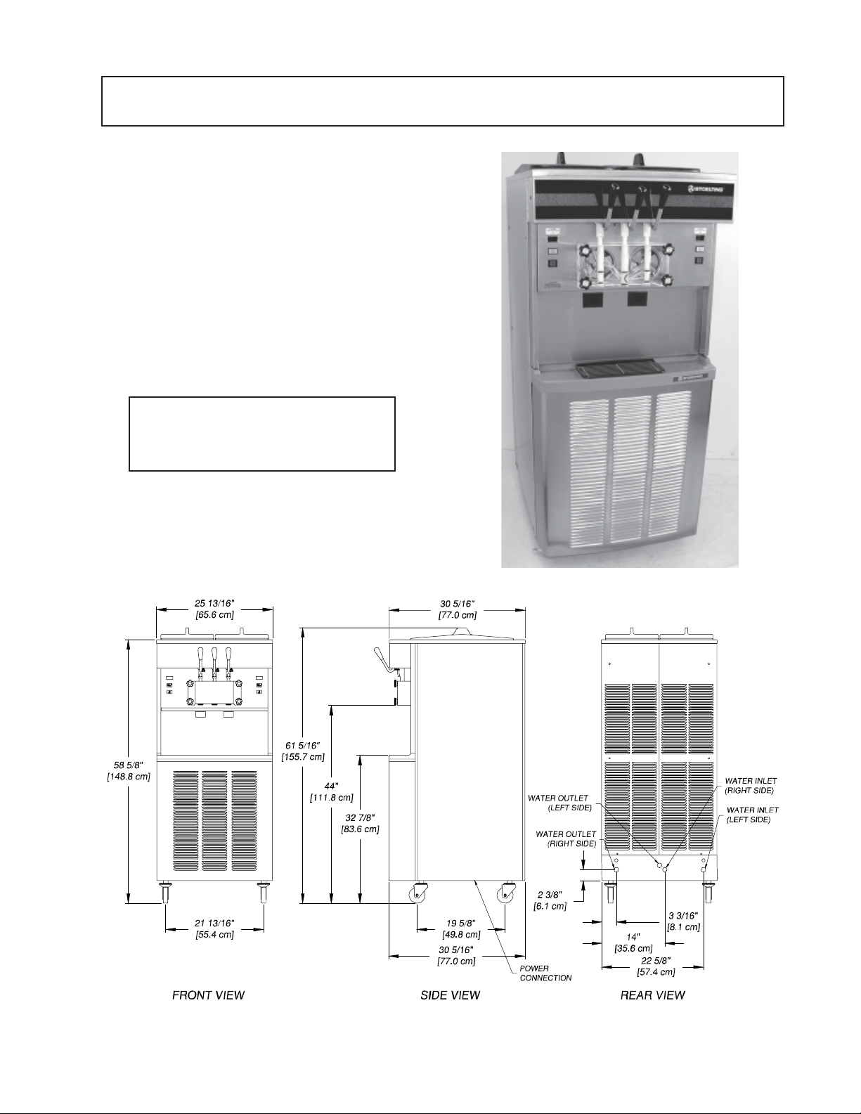
Figure 1. Model 4231G Freezer
Figure 2. Specifications
1
Page 8

1.2 SPECIFICATIONS
MODEL 4231G
FLOOR MODEL
GRAVITY FREEZER
DIMENSIONS
Freezer: 25.90” (65.81 cm) wide x 30.20” (76.7 cm)
deep x 60.80” (154.4 cm) high
Crated: 38.00” (96.5 cm) wide x 64.00” (162.5 cm) deep
x 70.00” (178.0 cm) high
WEIGHT
Freezer: 640 lbs. (291 kg)
Crated: 815 lbs. (370 kg)
ELECTRICAL
Refer to the nameplate located on the rear of the
Freezer.
COOLING
Air-cooled requires 3” (7.6 cm) clearance for all louvered
panels. Water-cooled requires ½” pipe or 5/8” inside
diameter copper water in be installed for adequate
water supply.
HOPPER CAPACITY
Two hoppers, 5.6 gallons (21 liters) each, refrigerated
and insulated.
2
Page 9
SECTION 2
INST ALLA TION INSTRUCTIONS
2.1 SAFETY PRECAUTIONS
Do not attempt to operate the freezer until the safety
precautions and operating instructions in this manual
are read completely and are thoroughly understood.
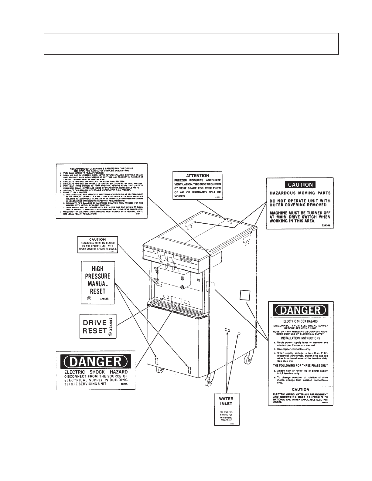
Take notice of all warning labels on the freezer (Fig. 3).
The labels have been put there to help maintain a safe
working environment. The labels have been designed
to withstand washing and cleaning. All labels must
remain legible for the life of the freezer.
Labels should be checked periodically to be sure they
can be recognized as warning labels.
If danger, warning or caution labels are needed, indicate
the part number, type of label, location of label, and
quantity required along with your address and mail to:
STOELTING, LLC
ATTENTION: Customer Service
502 HWY 67
Kiel, Wisconsin 53042-1600
Figure 3. Warning Label Locations
3
Page 10
2.2 SHIPMENT AND TRANSIT
The freezer has been assembled, operated and
inspected at the factory. Upon arrival at the final
destination, the freezer must be checked for any damage
that may have occurred during transit.
With the method of packaging used, the freezer should
arrive in excellent condition. THE CARRIER IS
RESPONSIBLE FOR ALL DAMAGE IN TRANSIT,
WHETHER VISIBLE OR CONCEALED. Do not pay the
freight bill until the freezer has been checked for damage.
Have the carrier note any visible damage on the freight
bill. If concealed damage and/or shortage are found
later, advise the carrier within 10 days and request
inspection. The customer must place claim for damages
and /or shortages in shipment with the carrier. Stoelting,
Inc. cannot make any claims against the carrier.
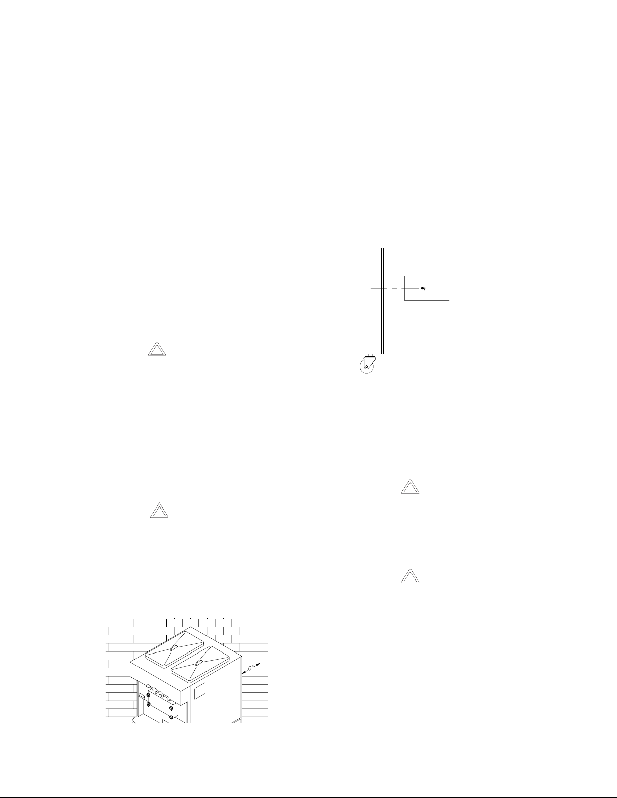
2.3 FREEZER INSTALLATION
NOTE
For Air Cooled Unit Only.
A rear block-off panel has been provided to prevent
recirculation of hot air beneath the freezer. The rear
block-off panel maximizes the efficiency of the freezer.
See the illustration for the installation instructions.
1. Remove both back panel mounting screws below
the bottom most louver.
2. Attach rear block-off panel to the back panel using
the same screws as shown.
ÅÅ
Å
ÅÅ
Bottom Most Louver Of Back Panel
ÅÅ
Å
ÅÅ
Back Panel Mounting Screw
ÇÇ
Ç
ÇÇ
Rear Blockoff Panel
CAUTION
FAILURE TO INST ALL THE FREEZER WITHIN
RECOMMENDED LIMITS WILL RESULT IN
POOR PERFORMANCE OF THE SYSTEM,
PREMATURE COMPONENT FAILURE AND
CANCELLATION OF WARRANTY.
Installation of the freezer involves moving the unit close
to its permanent location, removing all protective
packaging, setting in place and cleaning.
CAUTION
REMOVE LOWER FRONT PANEL BEFORE
REMOVING FREEZER FROM SKID.
A. The freezer requires adequate ventilation. A minimum
of 3” (7.6 cm) of vent space is required for free flow
of cooling air at the front and back (Fig. 4).
A water-cooled freezer requires an adequate water
supply, install 3/8 inch pipe or ½ inch inside diameter
copper water line to each side of the freezer. Connect
water outlet to a drain using a ½ inch inside diameter
line. Automatic washer hoses work well for final
connections. All water connections must comply with
local codes.
CAUTION
FLUSH ALL WATER LINES BEFORE
INSTALLATION. IN NEW STORES WITH
SEDIMENT WATER, ADD SUITABLE FILTER
OR STRAINER TO WA TER INLET.
CAUTION
FAILURE TO PROVIDE ADEQUATE
VENTILATION WILL VOID W ARRANTY .
Figure 4. Space and Ventilation Requirements
B. The unit is shipped without casters installed. To install
the casters, lift and support the unit while screwing
the four casters into the bottom of the frame at each
corner.
4
Page 11
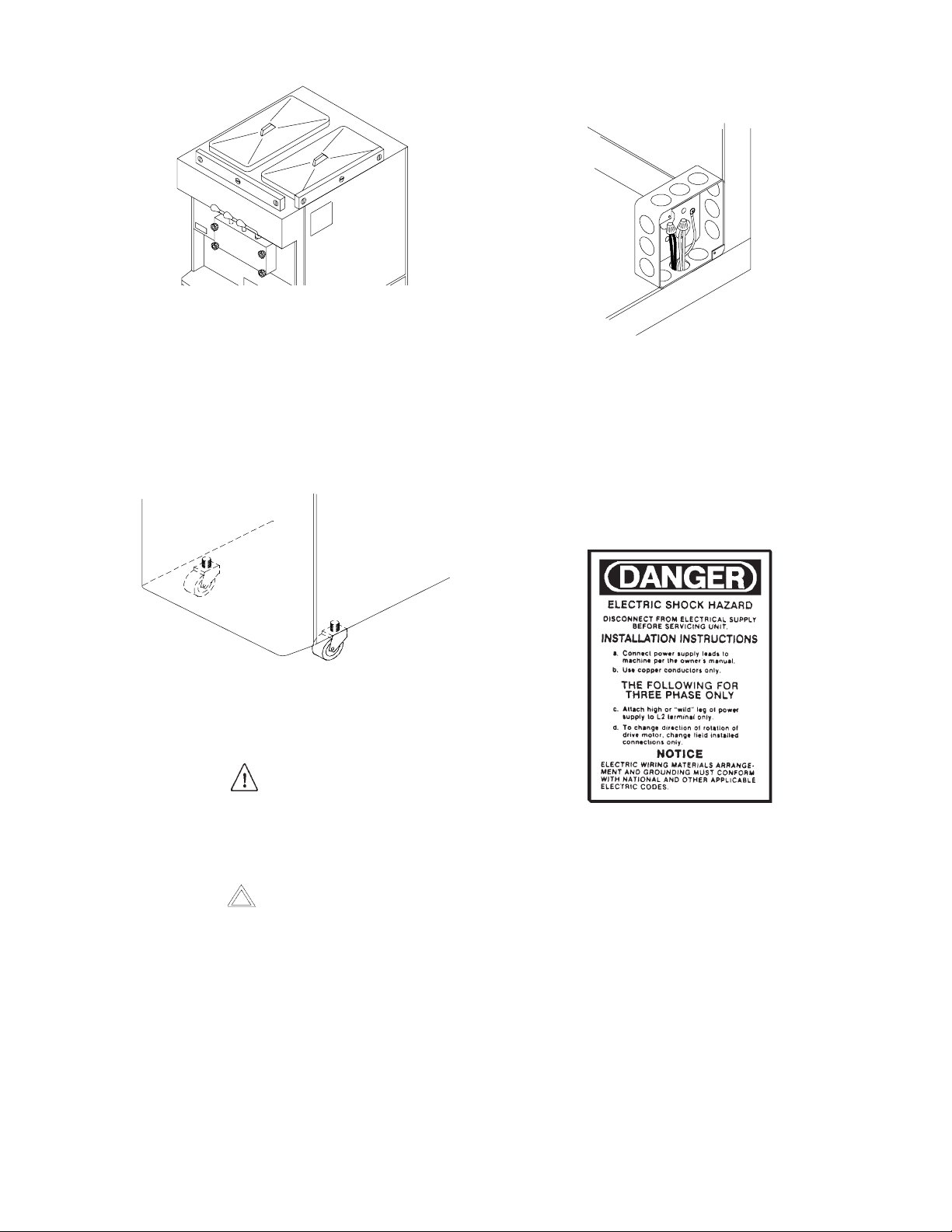
Figure 5. Leveling Freezer
C. For location of proper electrical connections, refer
to Figure 7.
C. Accurate leveling is necessary for correct drainage
of freezer barrel to insure correct over-run and flow.
Place a spirit level on top of the freezer at each
corner to check for level condition (Fig. 5). If
adjustment is necessary , level the freezer by turning
the casters in or out (Fig. 6).
Figure 6. Caster Adjustment
2.4 ELECTRICAL CONNECTIONS
WARNING
BEFORE INSTALLATION OF ANY CABLE IN
THE FREEZER, DISCONNECT THE FREEZER
FROM ITS ELECTRICAL SUPPLY SOURCE.
CAUTION
ROUTE ELECTRICAL CABLE SO THAT IT
CANNOT BE ACCIDENTALLY DAMAGED BY
PINCHING, CRUSHING, ETC.
Figure 7. Connecting Permanent Wiring
NOTE
When supply voltage is less than 218V , reconnect
transformer. Switch orange and red wires from
transformer at the terminal strip and cap blue wire.
D. Please read decal located on lower electrical box
cover (Fig. 8)
Figure 8. Danger Decal
The model 4231 freezer is two individual freezers in a
common enclosure. EACH SIDE MUST BE
CONNECTED INDIVIDUALLY. EACH SIDE MUST
HAVE ITS OWN ELECTRICAL SUPPLY. When making
the electrical supply connections, YOU MUST
MAINTAIN STRAIGHT POLARITY FROM SIDE TO
SIDE.
A. Connect freezer to a properly grounded 208/230 volt
(AC), source of electricity .
B. To access the electrical boxes, remove the two
Phillips head screws on the left and right side panels.
Then pull the panel down and out.
E. Check the auger shaft rotation by placing the MAIN
DRIVE switch in the CLEAN position. Auger shaft
rotation is clockwise as viewed through the clear
plastic front door. If the rotation is not clockwise, turn
the main electrical power OFF . Then reverse L1 and
L3 electrical power lines to the junction box (three
phase only). Re-check auger shaft rotation.
5
Page 12

6
Page 13
SECTION 3
INITIAL SET-UP AND OPERATION
3.1 OPERATOR’S SAFETY
PRECAUTIONS
SAFE OPERATION IS NO ACCIDENT; Observe these
rules:
A. Know the freezer. Read and understand the
Operating Instructions.
B. Notice all warning labels on the freezer.
C. W ear proper clothing. A void loose fitting garments,
and remove watches, rings or jewelry, which
could cause a serious accident.
D. Maintain a clean work area. Avoid accidents by
cleaning up the area and keeping it clean.
E. Stay alert at all times. Know which switch, push
button or control you are about to use and what effect
it is going to have.
Spigot Switch (behind panel)
Activated by Spigot Handles
F. Disconnect electrical cord for maintenance.
Never attempt to repair or perform maintenance on
the freezer until the main electrical power has been
disconnected.
G. Do not operate under unsafe operating
conditions. Never operate the freezer if unusual or
excessive noise or vibration occurs.
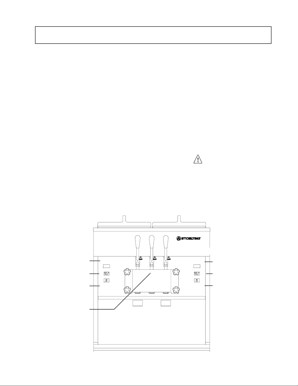
3.2 OPERATING CONTROLS AND
INDICATORS
Before operating the freezer, it is requires the operator
know the function of each operating control. Refer to
Figure 9 for the location of the operating controls on the
freezer.
WARNING
THE OFF-SERVE SWITCH MUST BE PLACED
IN THE OFF POSITION WHEN
DISASSEMBLING FOR CLEANING OR
SERVICING. THE FREEZER MUST BE
DISCONNECTED FROM ELECTRICAL SUPPL Y
BEFORE REMOVING ANY ACCESS PANEL.
Clean-Off-Serve Rocker Switch
Red Light (Push to Freeze)
Green Light (Ready to Serve)
Low Mix Light
Front Door Interlock Switch
Actuator (located between barrels behind stainless steel
panel)
Ì
Æ
Ê
Ì
Figure 9. Controls
È
Ê
7
Ë
ËË
Dispense Rate Adjusters
Ë
Ë
Å
É
Clean-Off-Serve Rocker Switch
Red Light (Push to Freeze)
Green Light (Ready to Serve)
Low Mix Light
High Pressure Reset Button (under lower front panel)
Water Cooled Only
Page 14

A. SPIGOT SWITCH
When the spigot handle is opened the SPIGOT
switch will start the auger drive motor and
refrigeration systems. When the spigot handle is
closed, the auger drive motor and compressor will
remain on until the product in the barrel reaches the
proper consistency.
NOTE
If the freezer shuts off and the PUSH TO FREEZE
light flashes, you have an error condition. Turn
the CLEAN-OFF-SERVE switch to the OFF
position, correct the problem and turn the freezer
back on.
GREEN LIGHT
B. CLEAN-OFF-SERVE SWITCH
The CLEAN-OFF-SERVE switch is a three-position
rocker switch used to control the operation of the
refrigeration system and auger. When the switch is
placed in the CLEAN position, the refrigeration
system will be off and the auger will rotate for
cleaning.
When the switch is placed in the OFF position, the
refrigeration system and auger will not operate.
When the switch is placed in the SERVE position,
the refrigeration system and auger will operate
automatically. The switch should be placed in the
ON position for normal operation.
C. PUSH TO FREEZE SWITCH
The illuminating PUSH TO FREEZE switch is used
to start the freezing cycle. During the initial freeze
down, the CLEAN-OFF-SERVE rocker switch is
placed in the SERVE position. Then the PUSH TO
FREEZE switch is pressed until the drive motor and
compressor comes “ON.”
NOTE
After the gearmotor starts, there is a 3-second
delay before the compressor starts.
The green lens is used to indicate that the product has
reached the proper consistency and is ready to be
dispensed.
NOTE
If the PUSH TO FREEZE lens is illuminated, push
the PUSH TO FREEZE switch and wait until the
green lens illuminates before dispensing.
MIX LOW LIGHT
The MIX LOW light is used to indicate when the hopper
is low on mix. When the light is illuminated fill the hopper
with mix.
CAUTION
FAILURE TO REFILL HOPPER IMMEDIATELY
MA Y RESULT IN OPERA TIONAL PROBLEMS.
D. DISPENSE RATE ADJUSTER
The dispense rate adjuster limits the opening of the
spigot.
To adjust product dispense rate, turn the adjusting
knob clockwise for slower flow and counterclockwise
for faster flow.
E. DOOR INTERLOCK SWITCH
During the normal operation, the red PUSH TO FREEZE
switch will illuminate after the freezer has been in idle for
the pre-set time. Before drawing product, press the red
PUSH TO FREEZE switch if it is illuminated. Wait until
the green lens is illuminated before dispensing.
When the door is securely fastened the freezer will
operate normally. When the door is removed, the
drive and compressor will not run.
8
Page 15

3.3 SANITIZING
Sanitizing must be done after the freezer is clean and
just before the hopper is filled with mix. Sanitizing the
night before is not effective. However, you should
always clean the freezer and parts after using it.
WARNING
THE UNITED STATES DEPARTMENT OF
AGRICULTURE AND THE FOOD AND DRUG
ADMINISTRATION REQUIRE THAT ALL
CLEANING AND SANITIZING SOLUTIONS
USED WITH FOOD PROCESSING EQUIPMENT
BE CERTIFIED FOR THIS USE.
B. Prepare 2 gallons (7.5 liters) of sanitizing solution
following manufacturer’s instructions. Pour into
hopper with mix inlet regulator in place (Fig. 11).
Figure 11. Sanitizing Procedure
When sanitizing the freezer, refer to local sanitary
regulations for applicable codes and recommended
sanitizing products and procedures. The frequency of
sanitizing must comply with local health regulations.
Mix sanitizer according to manufacturer’s instructions
to provide a 100 parts per million strength solution. Mix
sanitizer in quantities of no less than 2 gallons (7.5
liters) of 120°F water. Allow sanitizer to contact the
surfaces to be sanitized for 5 minutes. Any sanitizer
must be used only in accordance with the manufacturer’s
instructions.
CAUTION
PROLONGED CONTACT OF SANITIZER WITH
FREEZER MAY CAUSE CORROSION OF
ST AINLESS STEEL PARTS.
In general, sanitizing may be conducted as follows:
A. Push the mix inlet regulator fully into the hopper (Fig.
10).
C. Place the CLEAN-OFF-SERVE rocker switch in the
CLEAN position. Check for leaks around the front
door seal (Fig. 12).
Figure 12. Clean Control
D. Clean sides of hopper, mix inlet regulator and
underside of hopper cover using a sanitized soft
bristle brush dipped in the sanitizing solution (Fig.
13).
Figure 10. Mix Inlet Regulator
Figure 13. Sanitizing Hopper
9
Page 16

E. After five minutes, place the bucket under the spigots
and open all three spigots to drain the sanitizing
solution. When the solution has drained, place the
CLEAN-OFF-SERVE switch in the OFF position.
Allow the freezer barrel to drain completely (Fig. 14).
Figure 14. Spigot Opened and Solution Draining
3.4 FREEZE DOWN AND OPERATION
CAUTION
DO NOT OVERFILL THE HOPPER. MIX LEVEL
MUST NOT BE HIGHER THAN 2” (5CM) FROM
THE TOP OF THE AIR INLET TUBE ON THE
MIX INLET REGULA TOR.
E. The freezer barrel will automatically fill until it is about
½ full (about 3 min.) If the freezer barrel does not
fill, check for obstruction in the mix inlet regulator
“O” Ring, check for leaks at the mix inlet regulator
was installed correctly, or that the freezer is level.
F. Place the CLEAN-OFF-SERVE rocker switch in the
SERVE position, then press PUSH TO FREEZE
switch until the drive motor and compressor come
ON.
NOTE
After the gearmotor starts, there is a 3-second
delay before the compressor starts.
This section covers the recommended operating
procedures to be followed for the safe operation of the
freezer.
A. Sanitize just prior to use.
B. Place the CLEAN-OFF-SERVE switch in the OFF
position.
C. With spigot s open, pour approximately 1 gallon (3.8
liters) of mix into the hopper. Allow the mix to flush
out about 8 ounces (0.23 liters) of sanitizing solution
and liquid mix. Close the spigot. (Fig.15)
G. After about 6 to 10 minutes the freeze will shut OFF
and the green lens will illuminate. The product is
ready to serve. Freeze down time may be longer for
some frozen diet dessert mixes.
H. For normal dispensing, move the spigot handle open
60° (Fig. 16).
Figure 15. Pouring the Mix
D. Fill hoppers with approximately 6-1/2 gallons (11.4
liters) of pre-chilled (40°F or 4°C) mix.
Figure 16. Dispensing Product
CAUTION
REFRIGERATION IS AUTOMATICALLY
ACTIV ATED WHEN THE SPIGOT IS OPENED.
CLOSE THE SPIGOT COMPLETELY AFTER
DISPENSING.
10
Page 17

I. The freezer is designed to dispense the product at
a reasonable draw rate. If the freezer is overdrawn,
the result is a soft product or a product the will not
dispense at all. If this should occur, allow the freezer
to run for approximately 30 seconds before
dispensing additional product. After a while the
operator will sense or feel the freezer is beginning
to fall behind, and will slow down the rate of draw so
as not to exceed the capacity.
J. Do not operate the freezer when the level indicator
shows the hopper is empty.
NOTE
The freezer has a standby mode sometimes
referred to as a sleep or energy conservation
mode. When the freezer is not used, after a preset
time, it will remain there until someone draws a
product or pushes the PUSH TO FREEZE switch.
In the standby mode, the freezer will keep the
product below 45°F. Standby modes are not to
be used in place of cleaning and sanitizing.
Federal, State, and Local regulatory agencies
determine frequency of cleaning and sanitizing.
Mix does not improve with age. Old mix, or mix that has
been stored at too high a temperature, can result in a
finished product that is less than satisfactory from the
appearance and taste standpoint. To retard bacteria
growth in dairy based mixes; the best storage
temperature range is between 36° to 40°F (2.2° to
4.4°C).
Some products tend to foam more than others do. If
excess foam should occur, skim off with a sanitized
utensil and discard (Fig. 17). Periodically, stir the mix in
the hopper with a sanitized utensil.
Figure 17. Skimming the Foam
3.5 MIX INFORMATION
Mix can vary considerably from one manufacturer to
another. Differences in the amount of butterfat content
and quantity and quality of other ingredients have a
direct bearing on the finished frozen product. A change
in freezer performance that cannot be explained by a
technical problem may be related to the mix. When
changing from one type of mix to another such a yogurt
to Vitari, you may have to change the mix inlet regulator
and/or control settings. Please call your distributor for
further information.
Proper product serving temperature varies from one
manufacturer’s mix to another. Mixes should provide a
satisfactory product in the 18° to 20°F (-7° to -6°C)
range.
When checking the temperature, stir the thermometer
in the frozen product to read the true temperature.
3.6 REMOVING MIX FROM FREEZER
To remove the mix from the freezer, refer to the following
steps:
A. Remove the mix inlet regulator from the hopper by
pulling straight up (Fig. 18).
Figure 18. Removing Mix Inlet Regulator
11
Page 18

B. Place the CLEAN-OFF-SERVE rocker switch in the
CLEAN position. Allow the mix to agitate in freezer
barrel until the mix has become a liquid.
C. Drain the liquid mix by opening the spigot. A bucket
or container should be placed under the spigot to
catch the liquid mix (Fig. 19).
Figure 19. Draining Mix
E. Repeat steps A through D using a mild detergent
solution.
3.8 DISASSEMBLY OF FREEZER
PARTS
CAUTION
PLACE THE CLEAN-OFF-SERVE ROCKER
SWITCHES IN THE OFF POSITION BEFORE
DISASSEMBLING FOR CLEANING OR
SERVICING.
Inspection for worn or broken parts should be made at
every disassembly of the freezer for cleaning or other
purposes. All worn or broken parts should be replaced
to ensure safety to both the operator and the customer
and to maintain good freezer performance and a quality
product. Two normal wear areas are the auger flights
and front auger support bearing (Fig. 20). Frequency of
cleaning must comply with the local health regulation.
D. Place the CLEAN-OFF-SERVE switch in the OFF
position.
3.7 CLEANING THE FREEZER
NOTE
The frequency of cleaning the freezer and freezer
parts must comply with local health regulations.
After the mix has been removed from the freezer, the
freezer must be cleaned. To clean the freezer, refer to
the following steps:
A. Close the spigot and fill the hoppers with 2 gallons
(7.5 liters) of cold tap water.
B. Place the CLEAN-OFF-SERVE switches in the
CLEAN position.
C. Allow the water to agitate for approximately five
minutes.
Figure 20. Auger Flight Wear and Front
Auger Support Wear
To disassemble the freezer, refer to the following steps:
A. Remove the mix inlet regulators from the hoppers
by pulling straight up.
D. Open the spigots to drain the water. Remember to
place a bucket or container under the spigots to catch
the water. When the water has drained, turn the
CLEAN-OFF-SERVE switches to the OFF position.
Allow the freezer barrel to drain completely.
B. Remove the front door by turning off the circular
knobs and then pulling the front door off the studs
(Fig. 21).
12
Page 19

Figure 21. Removing Front Door
C. Remove rosette cap. Push the spigot body through
the bottom of the front door and remove the spigot
body (Fig. 22).
E. Remove the auger assemblies from the freezer. Pull
the augers out of the freezer barrel slowly. As the
augers are being pulled out, carefully remove each
of the plastic flights with springs (Fig. 24).
Figure 24. Auger Shafts
F. Keep the rear of the auger shafts tipped up once
they are clear of the freezer barrels to avoid dropping
rear seals.
Figure 22. Removing Spigot
D . Remove the front auger supports and bearings (Fig.
23).
G. Remove the rear seals.
H. Wipe socket lubricant from the drive end (rear) of
the auger with a cloth or paper towel.
I. Remove all “O” Rings from parts by first wiping off
the lubricant using a clean paper towel. Then
squeeze the “O” Ring upward with a dry cloth. When
a loop is formed, roll out of the “O” Ring groove (Fig.
25).
Figure 25. Removing O-Ring
Figure 23. Removing Auger Supports
WARNING
DO NOT USE ANY TYPE OF SHARP OBJECT
TO REMOVE THE “O” RINGS.
13
Page 20

J. Remove drain trays.
3.9 CLEANING THE FREEZER PARTS
Place all loose parts in a pan or container and take to the
wash sink for cleaning. To clean freezer parts refer to
the following steps:
B. Place all parts in the sanitizing solution, then remove
and let air dry.
C. Using this sanitizing solution and the large barrel
brush provided, sanitize the rear of the barrel and
drive area by dipping the brush in the sanitizing
solution and brushing the rear of the barrel.
A. Place all parts in warm mild detergent water and
clean with brushes provided. Rinse all parts with
clean hot water.
CAUTION
DO NOT DAMAGE PARTS BY DROPPING OR
ROUGH HANDLING.
B. Wash the hopper and freezer barrel with warm
detergent water and brush provided (Fig. 26).
3.11 ASSEMBLY OF FREEZER
To assemble the freezer parts, refer to the following
steps:
NOTE
Petro-Gel sanitary lubricant or equivalent must
be used when lubrication of parts is specified.
NOTE
The United States Department of Agriculture and
the Food and Drug Administration require that
lubricants used on food processing equipment
be certified for this use. Use lubricants only in
accordance with the manufacturer’s instructions.
A. Assemble all “O” Rings onto parts dry, without
lubrication. Then apply a thin film of sanitary
lubrication to exposed surfaces of the “O” Rings.
Apply thin film of sanitary lubricant to metal part of
rear seal. Also apply a thin film of sanit ary lubricant
inside the hole on the front of the auger.
Figure 26. Cleaning Freezer Barrel
C. Clean the drip tray and insert with a soap solution.
Rinse with clean hot water.
3.10 SANITIZE FREEZER AND
FREEZER PARTS
A. Use a sanitizer mixed according to manufacturer’s
instructions to provide a 100 parts per million
strength solution. Mix sanitizer in quantities of no
less then two gallons (7.5 liters) of 120°F water. Allow
the sanitizer to contact the surface for 5 minutes.
Any sanitizer must be used only in accordance with
the manufacturer’s instructions.
B. Assemble the rear seals onto the augers with the
large end to the rear. Be sure the “O” Ring is in place
before installing the rear seal.
C. Lubricate the inside of the auger drive sockets (rear)
with a small amount of white socket lubricant. A small
container of socket lubricant is shipped with the
freezer.
D. Screw the springs onto the studs in plastic flights.
Springs must be screwed into the flights
completely to provide proper tension (Fig. 27).
14
Page 21

Figure 27. Exploded View of Auger
CAUTION
DO NOT PLACE THE MIX INLET REGULA TOR
INTO THE HOPPER BEFORE INST ALLING THE
AUGER.
E. Install the two plastic flights onto rear of the auger
and insert part way into freezer barrel.
F. Install the remaining plastic flights, push the auger
into the freezer barrel and rotate slowly until the
auger engages the drive shaft.
G. Install the auger support and bearing into the front
of the augers with one leg of the support at 9 o’clock.
NOTE
Apply a small amount of Petro-Gel to the surface
of the cam on the spigot handle prior to assembly
of handle to the spigot body.
H. Install the spigot bodies with ”O” Rings into the front
door from the bottom (Fig. 28). Push straight up until
the spigots are in place. Install rosette cap.
I. Install the front door on the freezer.
J. Install the circular knobs on the freezer studs.
Figure 28. Exploded View of Front Door
CAUTION
FINGER TIGHTEN THE CIRCULAR KNOBS
EVENL Y. DO NOT OVERTIGHTEN KNOBS.
Look for the proper seal between the freezer barrel, “O”
Ring, and front doors.
K. Install the mix inlet regulators into the hopper with
the air inlet (long) tube toward the front of the freezer
(Fig. 29).
15
Page 22

Figure 29. Installing Mix Inlet Regulators
NOTE
Refer to Section 3.3 for sanitizing the
assembled freezer before filling with mix.
Figure 30. Drain Trays
L. Install the drain trays (Fig. 30).
CAUTION
DRAIN TRAYS MUST BE IN PLACE BEFORE
OPERATING FREEZER TO PREVENT
DAMAGE FROM POSSIBLE AUGER SEAL
LEAKS.
3.12 ROUTINE CLEANING
To remove spilled or dried mix for the freezer exterior,
simply wash in the direction of the finish with warm
soapy water and wipe dry. Do not use highly abrasive
materials, as they will mar the finish.
16
Page 23

SECTION 4
MAINTENANCE INSTRUCTIONS
4.1 PREVENTIVE MAINTENANCE
It is recommended that a preventive maintenance
schedule be followed to keep the freezer clean and
operating properly. The following steps are suggested
as a preventive maintenance guide.
WARNING
NEVER ATTEMPT TO REPAIR OR PERFORM
MAINTENANCE ON FREEZER UNTIL THE
MAIN ELECTRICAL POWER HAS BEEN
DISCONNECTED.
The United States Department of Agriculture and the
Food and Drug Administration require that lubricants
used on food processing equipment be certified for this
use. Use lubricants only in accordance with the
manufacturer’s instructions.
A. DAILY
3. Run a sanitized brush down mix inlet regulator
(carburetor) tubes (Fig. 32).
Figure 32. Sanitizing Mix Inlet Regulator
(Carburetor)
NOTE
When sanitizing, the skimmer, brush and the hand
that holds the mix inlet regulator (carburetor) must
also be sanitized.
1. The exterior should be kept clean at all times
to preserve the luster of the stainless steel. A
mild alkaline cleanser is recommended. Use a
soft cloth or sponge to apply the cleanser.
2. Using a sanitized one-pint aluminum overrun
container, skim the mix in the hopper to remove
any foam buildup (Fig. 31).
Figure 31. Skimming Hopper
4. Note any unusual noises or operating
conditions upon startup. Repair or rectify
immediately if problems exist.
NOTE
Do not use acid cleaners, strong caustic
compounds or abrasive materials to clean any
part of the freezer exterior or plastic parts.
CAUTION
INSPECTION FOR WORN OR BROKEN PARTS
SHOULD BE MADE AT EACH DISASSEMBLY
OF THE FREEZER.
B. WEEKLY
1. Check all “O” Rings for excessive wear and
replace if necessary .
2. Check scraper blades, front bearing and rear
bearing for wear damage (paragraph 3.8).
17
Page 24

C. MONTHLY
1. Check drive belt for wear.
2. Check condenser for dirt.
D. Blow out the dirt from the back of the condenser.
Most of the dirt will cling to the wet towel.
CAUTION
THIS PROCEDURE EMITS A LOUD NOISE.
4.2 FREEZE-UP
If a freeze-up does occur, use the following steps to
thaw the mix in the freezer barrel:
CAUTION
IF THE DRIVE BELT SQUEALS WHEN THE
CLEAN-OFF-SERVE SWITCH IS PLACED IN
THE SERVE POSITION, OR WHEN THE
SPIGOT IS OPENED TO DISPENSE PRODUCT ,
TURN THE CLEAN-OFF-SERVE SWITCH TO
THE OFF POSITION.
A. Check to make sure the spigot handle is closed
completely, spigot switch is functioning properly,
there is mix in the hopper, or the mix inlet regulator
(carburetor) is not plugged.
B. If drive motor overload was tripped, remove the
middle front panel and push the reset button. If it
will not reset wait 5 minutes and try again.
E. An alternative method is to clean with a condenser
brush and vacuum.
4.4 EXTENDED STORAGE
Refer to the following steps for winterizing the freezer
for winter lay-up or any extended period of storage.
A. Clean thoroughly with a warm mild detergent all
parts that come in contact with mix. Rinse in clear
water and dry all parts. Do not sanitize as prolonged
exposure of metal parts to some sanitizers can
cause corrosion.
NOTE
Do not let cleaning solution stand in freezer barrel
or hopper during the shutdown period.
B. Remove, disassemble, and clean the front door,
auger and mix inlet regulator (carburetor). Leave
disassembled during the shutdown period.
C. Place the CLEAN-OFF-SERVE switch in the SERVE
position and push the PUSH TO FREEZE switch.
D. The product will be ready to serve when the green
light illuminates.
E. If the freezer continues to freeze-up, contact a
qualified refrigeration service technician, local
distributor, or Stoelting, Inc.
4.3 CONDENSER SERVICE
A. Visually inspect the condenser for dirt by shining a
light through the louvers.
B. If the condenser is dirty, vacuum all loose dirt.
C. If using compressed air or CO-2 tank to blow out
the dirt, first place a wet towel over the front of the
condenser.
C. Place plastic auger flights, rear bearing and front
bearing in a plastic bag with a moist paper towel.
This will prevent parts from becoming brittle if
exposed to dry air over an extended period of time
(over 30 days).
CAUTION
BARREL MUST BE EMPTY FOR FOLLOWING
PROCEDURE.
D. On water cooled freezers, shut off and disconnect
water supply at rear of freezer; run compressor for
2 to 3 minutes to open water valve, and blow out all
water first through inlet, then outlet line, using air or
carbon dioxide.
E. Disconnect the freezer from the electrical supply in
the building.
18
Page 25

4.5 TROUBLESHOOTING
WARNING
NEVER ATTEMPT TO REPAIR OR PERFORM MAINTENANCE ON FREEZER UNTIL THE MAIN
ELECTRICAL POWER HAS BEEN DISCONNECTED.
Problem Possible Cause Remedy
Freezer does not run 1. Power to freezer is off. 1. Supply power to freezer
2. Fuse or circuit breaker is blown or tripped. 2. Replace or reset. (If condition continues
See note 1 or 2)
3. Freeze-up 3. See paragraph 4.3.
4. High-pressure cutout tripped 4. Correct problem and reset.
5. Drive motor OFF ON Timer. 5. Place the CLEAN-OFF-SERVE switch to
the OFF position the reset.
Freezer shuts off on error 1. Low or no mix in hopper. 1. Add mix.
2. Low or no overrun. 2. Check mix inlet regulator.
3. Refrigeration problem. 3. Check system. (See note 1.)
Product is too soft 1. No vent space for free flow of cooling air. 1. A minimum of 6 inches of vent space
required. (See paragraph 2.2).
2. Air temperature entering condenser is 2. Change location or direct hot
above 100°F. (Air cooled.) air away from freezer.
3. Condenser is dirty. (Air-cooled) 3. Clean (See paragraph 4.6).
4. Consistency setting too soft 4. Readjust (See paragraph 4.2).
5. Stabilizers in mix are broken down. 5. Remove mix, clean, sanitize and freeze
down with fresh mix.
6. Refrigeration problem. 6. Check system. (See note 1.)
Product is too firm. 1. Consistency setting too firm 1. Readjust. (See paragraph 4.2.)
2. Spigot not fully closed. 2. Fully close spigot.
Product does not 1. No mix in hopper 1. Fill hopper with mix.
Dispense. 2. Mix inlet regulator (carburetor) mix inlet 2. Unplug, using a small sanitized
tube is plugged. brush.
3. Special mix inlet regulator (carburetor) 3. Order special mix inlet
needed for mix being used. regulator (carburetor). (See note 2.)
4. Capacity of freezer is being exceeded. 4. Slow up on the draw rate.
5. Drive motor overloaded. 5. Place reset lever in the ON position. (If
condition continues see note 1 or 2.)
6. Drive belt failure. 6. See paragraph 4.4.
7. Freeze-up 7. See paragraph 4.3.
Drive belt slipping 1. Worn drive belt. 1. Replace drive belt. (See paragraph 4.4.)
2. Freeze-up 2. See paragraph 4.3.
19
Page 26

Low overrun 1. Mix inlet regulator (carburetor) missing. 1. Replace mix inlet regulator (carburetor).
2. Mix inlet regulator (carburetor) “O” Ring 2. Replace mix inlet regulator
missing. (carburetor) “O” Ring.
3. Mix inlet regulator (carburetor) air tube 3. Clean with sanitizer brush.
blocked.
Front door leaks. 1. Front door knobs are loose. 1. Tighten knobs.
2. Spigot parts are not lubricated. 2. See paragraph 3.11.
3. Chipped or worn spigot “O” Rings. 3. Replace “O” Rings.
4. “O” Rings or spigot installed wrong. 4. Remove spigot and check “O” Rings.
5. Spigot hole in front door nicked or 5. Replace front door.
scratched.
Hopper will not 1. EPR valve needs to be adjusted. 1. (See note 1.)
Maintain mix 2. Temperature control failure. 2. Replace. (See notes 1 or 2.)
temperature below 3. Refrigeration problem. 3. Check system. (See note 1.)
45°F (7°C).
1. Must be performed by a qualified service person.
2. The local dealer, distributor or Stoelting, LLC, Service Department should be contacted. Write or call:
Stoelting, LLC
502 Hwy. 67,
Kiel, WI 53042
Phone (920) 894-2293.
20
Page 27

SECTION 5
REPLACEMENT PARTS
5.1 HOW TO ORDER PARTS
To assure receipt of the proper replacement parts, supply
your dealer or distributor with the following information:
A. Model number of equipment.
B. Serial number of model, stamped on nameplate.
Part Number Description
324014 Decal Black Arrow
324141 Decal Caution Rotating Blades
324509 Decal Cleaning
324548 Decal Ventilation
324346 Decal Caution
324393 Decal – Drip Tray
324803 Decal – Header Panel (Stoelting Logo)
324804 Decal - Header Panel (Stoelting Swirl)
324806 Decal - Header Panel (A & W Logo)
324798 Decal – CLEAN/OFF/SERVE
324125 Decal – Elec. Shock Hazard
C. Part number, part name and quantity needed.
Common part names and numbers are listed in this
manual.
5.2 PUSH TO FREEZE LIGHT/SWITCH
LAMP REPLACEMENT
B. Remove the faulty lamp by pulling out the lamp puller
(See Fig. 33).
Figure 33. Push To Freeze Light/Switch Assembly
C. T o install the new lamp, line up the lamp end with the
receptacle and push fully in.
D. Reinstall the lens by pushing firmly in. When installed
“PUSH TO” might be right side up.
NOTE
LED light bulbs require correct polarity . If the bulb
does not illuminate, remove the bulb, turn 180°
and replace.
5.3 CLEAN-OFF-SERVE ROCKER
SWITCH REPLACEMENT
A. Remove side panel.
To change a lamp in the PUSH TO FREEZE switch/light
follow these simple steps:
A. Grasp the lens with your thumb and forefinger and
pull out.
WARNING
DISCONNECT FREEZER FROM ELECTRICAL
SUPPL Y SOURCE BEFORE SERVICING .
21
Page 28

5.4 REPLACEMENT PARTS & REFERENCE DRAWINGS
Rosette Cap
26
34. Spigot, Front Door and Auger Assembly
22
Page 29

1 2177428 1 Door w/pins
Item Stoelting PN Qty Description
2 3159696 2 Spigot, Outside
3 3158086 1 Spigot, Center
4 624598 4 O-Ring, 7/8 OD x 1/8 CS
5 624664 1 O-Ring 1-5/16 OD x 1-1/16 ID x 1/8 CS
6 625133 2 O-Ring 4.00" OD x .1875" CS
7 508135 As Reqd Lube, Petro-Gel
8 482019 4 Knob with 3/8-16 (Black)
9 624614 2 O-Ring, 1 OD x ¾ ID x 1/8 CS
10 482004 3 Knob
11 644094 6 Screw, Cap ¼-20 x 3/8 Hex Hd
12 4158215 3 Glide Bracket Weldment
13 2158260 3 Handle
14 570961 3 Pin, Cotterless Clevis
15 428045 3 Knob, Black Plastic
16 2158082 3 Glide
23
17 1158080 3 Adjusting Bar
18 647995 3 Screw, Machine ¼-20 x 3.50" Long
19 718773 4 Switch
20 647055 8 Screw, Machine #4-40 x .625" Long
21 538235 8 Nut, Hex #4-40
22 766917 8 Washer, Shakeproof #4
23 696048 2 Spring, Torsion (Outside Spigot)
23 696044 1 Spring Torsion (Center Spigot)
24 694247 3 Spring
25 1145194 2 Mix Inlet Reg. (1/4" Hole, Std Length)
25A 1146231 2 Mix Inlet Reg. (5/16" Hole, Std Length)
25B 1150832 2 Mix Inlet Reg. (1/4" Hole, Ext. Length)
25C 1150807 2 Mix Inlet Reg. (5/16" Hole, Ext. Length)
26 232734 3 Rosette Cap
Page 30

242526
Page 31

Page 32

Page 33

29 2172761 2 Water Valve Bracket (W/C Only)
30 644024 4 Screw Mach 8-32 x 1/4 Hx (W/C Only)
31 766941 4 Washer Shakeproof #8 (W/C Only)
32 2172763 2 Pressure Switch Bracket (W/C Only)
Item Stoelting PN Qty Description
33 538335 4 Nut Hex 1/4-20 x 7/16 Stl Zp
34 766456 4 Washer Round 5/8 x 9/32 Steel
35 647393 4 Screw Mach 6-32 x 3/8 Rd Hd Ph
36 766933 4 Washer Shakeproof 6 x 5/16
37 644106 4 Screw Cap 1/4-20 x 5/8 Hx Hd
38 522833 2 Fan Motor (A/C Only)
39 3171824 2 Bracket, Condenser (A/C Only)
40 4154716 1 Condenser Shroud (A/C Only)
41 162067 2 Blade, Fan (A/C Only)
42 284044 1 Condenser (A/C Only)
43 538280 8 Nut, Hex #8-32 (A/C Only)
44 766948 8 Washer, Shakeproof #10 (A/C Only)
45 538297 8 Nut, Hex #10-24 (A/C Only)
46 649000-37 4 Screw, Self Tap 10-24 (A/C Only)
47 732133 2 Wire Nut (Crimp) (A/C Only)
48 524075 4 Mount Motor Ring
49 524074 6 Mount Motor Bushing
50 221637 4 Bushing Support (Shaft End)
51 766566 8 Washer .406 ID x 2.5 OD x 14 GA
52 1145141 2 Motor Adjusting Stud
53 538344 2 Nut Hex 5/16-18 x 1/2 Stl Zp
54 1150893 2 Bushing Support (Opposite Shaft End)
55 649109 4 Screw Tap 10-16 x 1/2 Ind. Hx
56 538395 2 Nut Hex 1/2-13 x 3/4 x 5/16 Zp
57 538360 4 Nut Hex Full 3/8-16 Zp
58 538356 4 Nut Hex Locking Flange Zp
59 231083 2 Start Capacitor
60 231082 2 Run Capacitor
1 152294 4 Belt V, 39.2 O.L. x 38.3 P.L.
2 282021-SV 2 Compressor (4231-18G, -38G)
Item Stoelting PN Qty Description
2A 282020-SV 2 Compressor (4231-109G, -309G)
2B 282030 2 Compressor (4231-102G, -302G)
3 422156 2 Grommet Kit with sleeves
4 644371 8 Screw Cap 5/16-18 x 1-3/4 Hx
5 767211 8 Washer Flat 5/16, 7/8 x 3/8 x 14GA
6 522844 2 Motor, 2HP (1 PH & 3 PH, 60 HZ) (SER.#0 - 16068)
6 522856 2 Motor, 2 HP (1 PH & 3 PH, 60 HZ) (SER.#16069 Plus)
6A 523082 2 Motor, 2HP (50 HZ)
7 1145153 2 Pulley (1 PH & 3 PH, 60 HZ)
7A 1147928 2 Pulley (50 HZ)
8 614232 2 Speed Reducer 5:2:1 Reduction
9 628046 16 Rivet Blind 1/4
10 644091 4 Screw Cap 1/4-20 x 1/2 Hx Hd
11 644605 8 Screw Cap 3/8-6 x 2 Hx Hd Zp
12 714006 36” 1” x 100’ Roll/Rubber
13 766964 4 Washer Shakeproof 1/4 Zinc
14 766982 8 Washer Shakeproof 3/8 Zinc
15 M820072 .001 Sealant-White Adhesive
16 2147034 2 Pulley, 7.00 PD Machined
27
17 4172774 1 Hopper & Evap. Foamed
18 119421 4 Angle (Vertical Extrusion)
19 628038-04 16 Rivet 3/16 Dia. x .62 Lg.
20
21 284104 2 Condenser (W/C Only)
22 644307 8 Screw Cap 5/16-18 x 3/4 (W/C Only)
23 538351 2 Nut Hex 5/16-18 Locking (W/C Only)
24 766073 6 Washer Lock 5/16 (W/C Only)
25 2172762 1 Condenser Joining Bracket (W/C Only)
26 767205 6 Washer Flat 1/4 x 3/4 x 5/16 (W/C Only)
Page 34

28
Page 35

25 718750 2 Switch, Rocker
Item Stoelting PN Qty Description
26 732118 16 Terminal Panel Mount (Red)
27 732119 2 Terminal Housing (Red)
28 223007 4 Bushing Snap 5/8ID 3/4 Mtg.
29 295109 4 Contactor Mag 3-Pole 24V
30 766948 8 Washer Shakeproof 10 Zinc Plate
31 644048 8 Screw Mach 10-24 x 1/2 Hx Hd
32 538913 8 Nut Speed 10-24 x 37/64 x 5/8
33 231084 2 Capacitor, Run (4231-18G,-38G)
34 231079 2 Capacitor, Start (4231-18G,-38G)
35 647513 8 Screw Mach 8-32 x 3/8 Rd Hd Ph
36 2141450 2 Capacitor Bracket 50 HZ
37 766940 34 Washer Shakeproof 8 Zinc Plate
38 618157 2 Relay, Motor Start (4231-18G,-38G)
39 647529 10 Screw Mach 8-32 x 1/2 Rd Hd PH
40 744142 2 Transformer Assy
41 647536 4 Screw Mach 8-32 x 5/8 Rd Hd Ph
42 732019 2 Terminal Block 5 Contacts
43 1141398 2 Varistor Assy 24 Volt
44 4177141 1 Power Box Weldment
45 739527 2 Timer, Interval 24 Vac
46 1170811 1 Decal Clean Timer
47 732020 2 Terminal Block 8 Pole
1 649109 4 Screw Tap 10-16 x 1/2 Ind. Hx
Item Stoelting PN Qty Description
2 524091 2 Mount Adhesive Back 1 x 1 Plastic
3 647885 2 Screw Mach 1/4-20 x 1/2 Trs Hd
4 538922 2 Nut Speed 1/4-20
5 766964 6 Washer Shakeproof 1/4 Zinc
6 644195 4 Screw Cap 1/4-20 x 2 Hx Hd
7 1172773 4 Spacer, 1.47 Long
8 2158124-SV 1 Door Interlock Switch Assy
9 766949 2 Washer Shakeproof #10 Cntsink
10 647671 2 Screw Mach 10-24 x 1/2 Fl Hd
11 458105 2 Indicator, Mix Low
12 1154882 2 Switch, Push-To-Freeze Assembly
13 296179 2 Control Liquid Level 24V
14 524087 8 Mount Dual Lock Circuit Spacer
15 538296 4 Nut Hex #10-24 x 3/8 SS
16 538912 4 Nut Speed 10-24 x 47/64 x 9/16
29
17 2172828 2 Mix Probe Assembly
18 766430 2 Washer Round
19 1157996 2 Spacer
20 3158218 2 Control Board Bracket
21 521721 2 Module, Control Power Board
22 521554 2 Module, Control-Logic Board 608
23 647376 16 Screw, Machine #6-32 x 1/4”Lg.
24 766933 16 Washer, Shakeproof #6
Page 36

Page 37

Item Stoelting PN Qty Description
1 282021-SV 2 Compressor (4231-18G, -38G)
2A 282020-SV 2 Compressor (4231-109G, -309G)
2B 282030 2 Compressor (4231-102G, -302G)
3 4172774 1 Hopper & Evaporator Assembly
4 284104 2 Condenser (W/C Only)
4A 284044 1 Condenser (A/C Only)
5 718686 2 Switch Pressure (W/C Only)
6 342008 2 Drier, Filter
7 762277 2 Check Valve (Magni-Chek)
8 762445 2 Expansion Valve
31
9 342020 2 Drier Refrigeration
10 458010 2 Indicator, Sight Glass
11 763455 2 Valve Solenoid
12 375813 6 Access Fitting Assembly
13 282085 6 Cap Quick Seal
14 762359 6 Valve Core
15 231101-SV 2 Capillary Tube
16 1158278 2 Valve, EPR
Page 38

Page 39

Item Stoelting PN Qty Description
1 282021-SV 2 Compressor (4231-18G, -38G)
2A 282020-SV 2 Compressor (4231-109G, -309G)
2B 282030 2 Compressor (4231-102G, -302G)
3 4172774 1 Hopper & Evaporator Assembly
4 284104 2 Condenser (W/C Only)
4A 284044 1 Condenser (A/C Only)
5 718686 2 Switch Pressure (W/C Only)
6 342008 2 Drier, Filter
7 762277 2 Check Valve (Magni-Chek)
8 762445 2 Expansion Valve
33
9 342020 2 Drier Refrigeration
10 458010 2 Indicator, Sight Glass
11 763455 2 Valve Solenoid
12 375813 6 Access Fitting Assembly
13 282085 6 Cap Quick Seal
14 762359 6 Valve Core
15 231101-SV 2 Capillary Tube
16 1158278 2 Valve, EPR
Page 40

Page 41

WARRANTY
SOFT SERVE / SHAKE FREEZERS
1. Scope:
Stoelting, LLC warrants to the first user (the “Buyer”) that the freezer cylinders, hoppers, compressors, drive motors,
speed reducers, auger and auger flights of Stoelting soft serve / shake freezers will be free from defects in materials
and workmanship under normal use and proper maintenance appearing within five (5) years, and that all other
components of such equipment manufactured by Stoelting will be free from defects in material and workmanship
under normal use and proper maintenance appearing within twelve (12) months after the date that such equipment is
originally installed.
2. Disclaimer of Other Warranties:
THIS W ARRANTY IS EXCLUSIVE; AND STOEL TING HEREBY DISCLAIMS ANY IMPLIED W ARRANTY OF MERCHANTABILITY OR FITNESS FOR PA RTICULAR PURPOSE.
3.
Remedies:
Stoelting’s sole obligations, and Buyer ’s sole remedies, for any breach of this warranty shall be the repair or (at
Stoelting’s option) replacement of the affected component at Stoelting’s plant in Kiel, Wisconsin, or (again, at
Stoelting’ s option) refund of the purchase price of the affected equipment, and, during the first twelve (12) months of
the warranty period, deinstallation/reinstallation of the affected component from/into the equipment. Those obligations/remedies are subject to the conditions that Buyer (a) signs and returns to Stoelting, upon installation, the
Checklist/Warranty Registration Card for the affected equipment, (b) gives Stoelting prompt written notice of any
claimed breach of warranty within the applicable warranty period, and (c) delivers the affected equipment to Stoelting
or its designated service location, in its original packaging/crating, also within that period. Buyer shall bear the cost
and risk of shipping to and from Stoelting’ s plant or designated service location.
4. Exclusions and Limitations :
This warranty does not extend to parts, sometimes called “wear parts”, which are generally expected to deteriorate
and to require replacement as equipment is used, including as examples but not intended to be limited to o-rings,
auger seals, auger support bushings and drive belts. All such parts are sold
AS IS.
Further, Stoelting shall not be responsible to provide any remedy under this warranty with respect to any component
that fails by reason of negligence, abnormal use, misuse or abuse, use with parts or equipment not manufactured or
supplied by Stoelting, or damage in transit.
THE REMEDIES SET FORTH IN THIS W ARRANTY SHALL BE THE SOLE LIABILITY STOEL TING
AND THE EXCLUSIVE REMEDY OF BUYER WITH RESPECT TO EQUIPMENT SUPPLIED BY
STOEL TING; AND IN NO EVENT SHALL STOEL TING BE LIABLE FOR ANY INCIDENT AL OR
CONSEQUENTIAL DAMAGES, WHETHER FOR BREACH OF W ARRANTY OR OTHER CONTRACT BREACH, NEGLIGENCE OR OTHER T ORT, OR ON ANY STRICT LIABILITY THEORY .
 Loading...