

Stoelting 217R-109G Service Manual

Challenger Series
OPERATORS MANUAL
Manual No. 513562 Rev.2


This manual provides basic information about the machine. Instructions and suggestions are
given covering its operation and care.
The illustrations and specifi cations are not binding in detail. We reserve the right to make
changes to the machine without notice, and without incurring any obligation to modify or provide new parts for machines built prior to date of change.
DO NOT ATTEMPT to operate the machine until instructions and safety precautions in this
manual are read completely and are thoroughly understood. If problems develop or questions
arise in connection with installation, operation, or servicing of the machine, contact Stoelting.
stoeltingfoodservice.com
Stoelting Foodservice Equipment
502 Highway 67
Kiel, WI 53042-1600
U.S.A.
Main Tel: 800.558.5807
Fax: 920.894.7029
Customer Service: 888.429.5920
Fax: 800.545.0662
Email: foodservice@stoelting.com
© 2014 PW Stoelting, LLC
A Few Words About Safety
Safety Information
Read and understand the entire manual before
operating or maintaining Stoelting equipment.
This manual provides the operator with information
for the safe operation and maintenance of Stoelting
equipment. As with any machine, there are hazards
associated with their operation. For this reason safety
is emphasized throughout the manual. To highlight
specifi c safety information, the following safety defi ni-
tions are provided to assist the reader.
The purpose of safety symbols is to attract your attention to possible dangers. The safety symbols, and
their explanations, deserve your careful attention
and understanding. The safety warnings do not by
themselves eliminate any danger. The instructions
or warnings they give are not substitutes for proper
accident prevention measures.
If you need to replace a part, use genuine Stoelting
parts with the correct part number or an equivalent
part. We strongly recommend that you do not use
replacement parts of inferior quality.
Safety Alert Symbol:
This symbol Indicates danger, warning or caution.
Attention is required in order to avoid serious personal injury. The message that follows the symbol
contains important information about safety.
Signal Word:
Signal words are distinctive words used throughout
this manual that alert the reader to the existence and
relative degree of a hazard.
WARNING
The signal word “WARNING” indicates a potentially
hazardous situation, which, if not avoided, may result
in death or serious injury and equipment/property
damage.
CAUTION
The signal word “CAUTION” indicates a potentially
hazardous situation, which, if not avoided, may result
in minor or moderate injury and equipment/property
damage.
CAUTION
The signal word “CAUTION” not preceded by the
safety alert symbol indicates a potentially hazardous
situation, which, if not avoided, may result in equipment/property damage.
NOTE (or NOTICE)
The signal word “NOTICE” indicates information or
procedures that relate directly or indirectly to the
safety of personnel or equipment/property.

TABLE OF CONTENTS
SECTION 1 - DESCRIPTION AND SPECIFICA TIONS
1.1 Description ......................................................................................................................1
1.2 Specifications ..................................................................................................................1
SECTION 2 - INST ALLATION
2.1 Shipment and T ransit........................................................................................................3
2.2 Installation ........................................................................................................................ 3
2.3 Remote Condenser.......................................................................................................... 5
2.4 Mix Pump Installation and Checkout (Remote Models)......................................................7
SECTION 3 - OPERA TING INSTRUCTIONS
3.1 Safety Information............................................................................................................. 9
3.2 Safety Precautions ...........................................................................................................10
3.3 Operating Controls ...........................................................................................................11
3.4 Spigot Switch...................................................................................................................11
3.5 Drive Motor Overload .......................................................................................................11
3.6 Power Switch (CLEAN-OFF-SERVE) ..............................................................................11
3.7 Freezing Switch................................................................................................................11
3.8 Door Interlock Switch........................................................................................................ 11
3.9 Remote Pump Switch.......................................................................................................11
3.10 Dispense Rate Adjuster .................................................................................................11
3.1 1 High Pressure Cut Out....................................................................................................11
3.12 Sanitizing Procedures ....................................................................................................11
3.13 Initial Freeze Down and Operation.................................................................................. 12
3.14 Removing Mix From the Freezer..................................................................................... 13
3.15 Disassembly and Assembly of Front Door (Model 217 and 238R) ..................................14
3.16 Disassembly and Assembly of Auger ............................................................................. 16
3.17 Disassembly and Assembly of Mix Line Adaptor (Remote Models) ................................17
3.18 O-Ring Removal and Care .............................................................................................17
3.19 Cleaning of Freezer and Freezer Parts...........................................................................17
3.20 Sanitize Freezer Parts....................................................................................................18
SECTION 4 - MAINTENANCE INSTRUCTIONS
4.1 Freezer Adjustments ........................................................................................................ 19
4.2 Product Temperature Adjustment...................................................................................... 19
4.3 Drive Belt T ension Adjustment ..........................................................................................19
4.4 Condenser Cleaning (Air-Cooled Freezers) .....................................................................19
4.5 Preventative Maintenance ................................................................................................ 20
4.6 Extended Storage ............................................................................................................20
4.7 Troubleshooting................................................................................................................ 20
SECTION 5 - HOW TO ORDER REPLACEMENT PARTS
5.1 How T o Order Replacement Part s ....................................................................................23
5.2 Parts List and Reference Drawings ..................................................................................23

LIST OF ILLUSTRATIONS
Figure Title Page
1 Caster Options ...................................................................................................... 3
2 Water Connections................................................................................................ 4
3 Electrical Connections........................................................................................... 4
4 Auger Shaft Rotation ............................................................................................. 5
5 Remote Condenser ............................................................................................... 6
6 Mix Transfer Line & Pump Installation .................................................................... 8
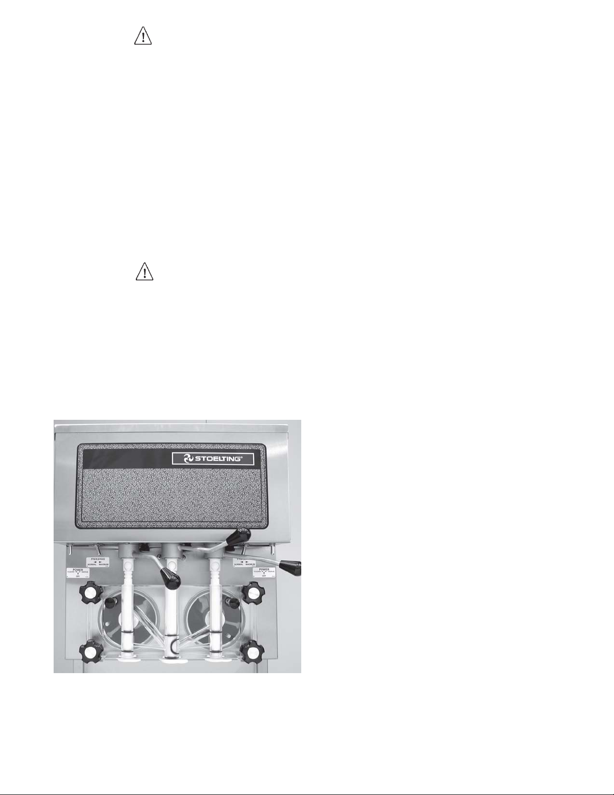
7 Warning Label Locations....................................................................................... 10
8 Operating Controls ................................................................................................ 11
9 Air Bleed............................................................................................................... 12
10 Pump Switch ......................................................................................................... 12
11 Front Door Disassembly........................................................................................ 14
12 Spinner Assembly ................................................................................................. 15
13 Auger with Rubber Rear Seal ................................................................................ 16
14 Auger Disassembly ............................................................................................... 16
15 Plastic Parts.......................................................................................................... 16
16 Auger Assembly.................................................................................................... 16
17 Auger Flight Spring ............................................................................................... 17
18 Mix Line Adapter ................................................................................................... 17
19 Removing O-rings ................................................................................................. 17
20 Potentiometer........................................................................................................ 19
21 Belt Adjustment ..................................................................................................... 19
SECTION 1
DESCRIPTION AND SPECIFICATIONS
1.1 DESCRIPTION
The Stoelting Challenger pressurized freezers are available in water cooled or air cooled versions (completely selfcontained or with remote condensers). Some models are available with built-in hoppers or remote mix pump feed.
Freezers are equipped with fully automatic controls to provide for consistent temperature and uniformity of product.
Refer to Mix Pump Manual for complete information on the operation of the mix pump.
1.2 SPECIFICATIONS
LEDOM NOITPIRCSED
712elytSpmuPreppoH-evreStfoS-lerraBelgniS
R712elytSpmuPetomeR-evreStfoS-lerraBniwT
R522elytSpmu
R832elytSpmuPetomeR-evreStfoS-tsiwThtiwlerraBniwT
LEDOM
71283/515.99/52.93361/52.467.381/504
R71283/515.99/52.935.451/57.061.071/573
R52283/515.99/52.935.451/5
R8326.04/617.99/52.933.451/57.06223/017
HTDIW
mc/ni
:STNEMERIUQERLACIRTCELE
mc/ni
PetomeR-ekahS-rennipShtiwlerraBelgniS
ekahsPH0.2dnaevrestfosPH5.2ahtiw,rotomevirdPH2aedulcnisledomevobaehT
isrepreppoh)retil7.42(nollag5.6evahsrezeerfdeniatnoc
HTPED
THGIEH
mc/ni
7.065.471/583
-fleS.rosserpmoc
.pmupxim912ledomgnitleotSahtiw,ed
.TWTEN
gk/bl
.elbaliavaeraztreh06,stlov032/802,esahp3rotlov032,esahP1-citsemoD
.stnemeriuqercificepsrofrezeerfehtforaerehttaetalpemanlacirtceleotrefeR-
acoltekcapnoitamrofninisimargaidgniriW-
1
.lenapredaehtnorfro,lenapedistfeldnihebdet

2
SECTION 2
INSTALLATION
2.1 SHIPMENT AND TRANSIT
The freezer has been assembled, operated, and inspected
at the factory . For shipment, the freezer is placed on skids,
with small parts placed separately in boxes. Upon arrival
at the final destination, the freezer must be checked for
any damage which may have occurred during final transit.
With the sturdy packaging used, the equipment should
arrive in satisfactory condition. THE CARRIER IS RESPONSIBLE FOR ALL DAMAGE IN TRANSIT , WHETHER
VISIBLE OR CONCEALED. Do not pay the freight bill until
you have checked the equipment. Have the carrier note
any visible damage on the freight bill. If concealed damage and or shortage is found later advise the carrier within
ten days and request inspection. The customer must place
claim for damage and/or shortages in shipment with the
carrier. Stoelting, Inc. cannot make any claims against
the carrier.
2.2 INSTALLA TION
Installation of the freezer involves moving the freezer close
to its permanent location, removing all protective packaging, setting in place and cleaning.
A. Remove all protective packaging. Remove the hold
down bolts from the wooden pallet, and walk freezer
off the pallet.
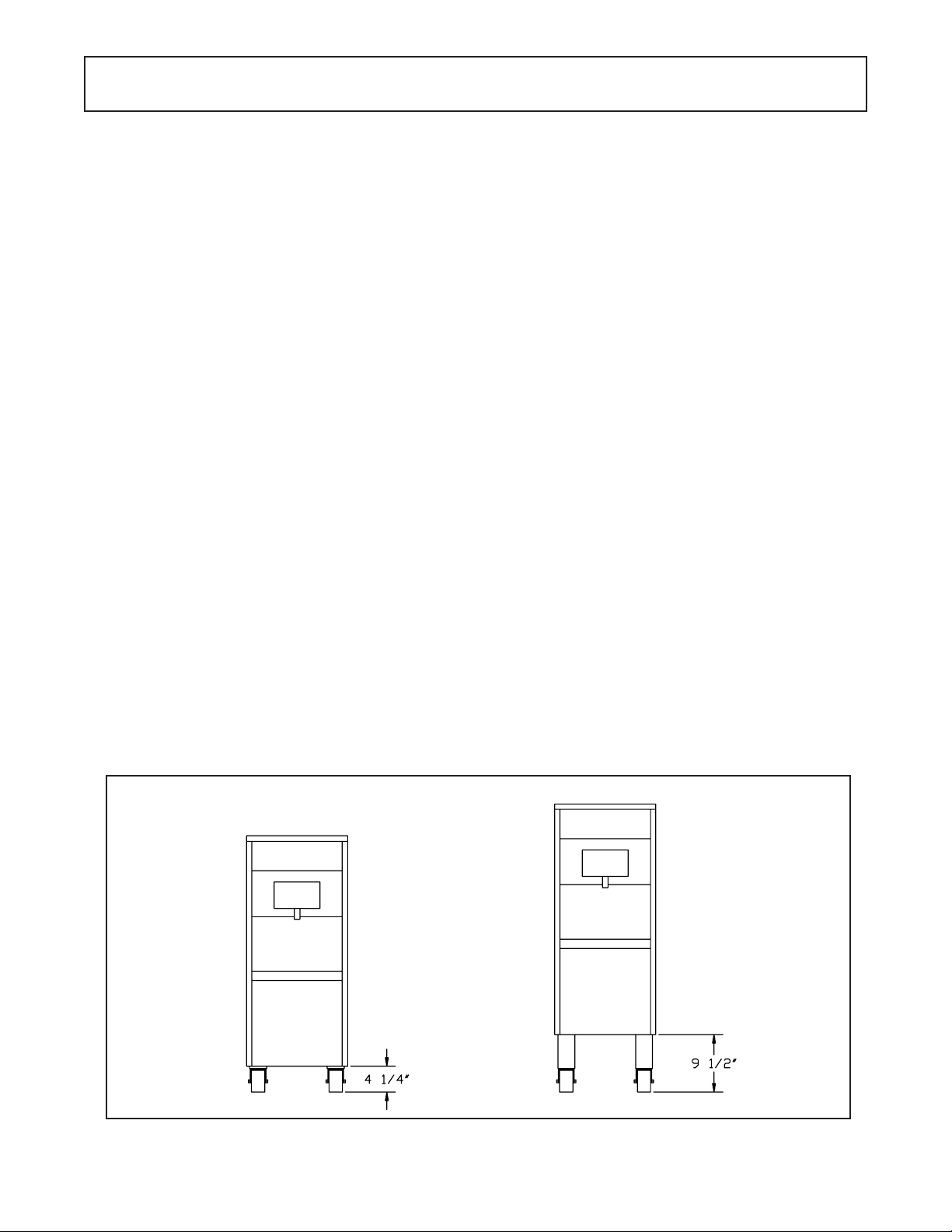
B. The freezer is shipped without legs. To install legs,
lift freezer and screw caster , extension, or leg into
the bottom of frame at each corner. Refer to caster
and leg options in Figure 1.
Warning
FREEZER MUST NOT BE ALLOWED TO TIP
MORE THAN 10°. FAILURE TO HEED THIS WARNING COULD RESUL T IN THE FREEZER FALLING
ON IT’S SIDE CAUSING SERIOUS DAMAGE OR
INJURY.
C. T o level turn the top p art of the caster or the bottom
part of the leg in or out. Then level by placing a level
on top of the freezer at each corner.
NOTE
Leveling is necessary for correct freezer drainage.
D. For all freezers allow a minimum of 6 inches of space
at the front and rear for air circulation. For efficient
operation, the room temperature should not be be
low 60° F (16° C) or above 90° F (32° C).
E. For water cooled freezers, install a minimum of 1/2
inch pipe or 5/8 inch inside diameter copper water
line to the freezer . The water line must be connected
in a manner that will comply with local codes and
allow adequate room for servicing.
NOTE
All external plumbing is to be supplied by the customer.
Water lines connect to fittings at the rear of the freezer.
(See Fig.2) Connect the clean, potable, water inlet to water
source using flexible high water pressure line. Ordinary
garden hose is not recommended. Connect the water outlet to flexible plastic tubing. The outlet can be secured to
floor drain, as the outlet is clean, warm water.
Option B - Casters & ExtensionsOption A - Casters
Figure 1. Caster Options
For Models 217, 217R, 225R, 238R
3
Water Out
Water In
Figure 2
Water Connections
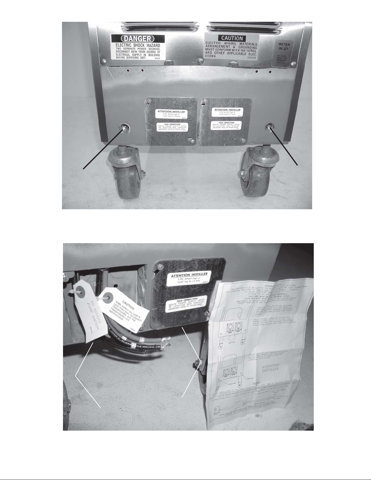
Access Holes
Electrical Connections
Figure 3
4
CAUTION
FLUSH ALL WA TER LINES BEFORE INST ALLATION. IN NEW STORES WITH SEDIMENT IN
WA TER, ADD SUIT ABLE FIL TER OR STRAINER
TO WATER INLET. FAILURE TO FLUSH ALL
WATER LINES MAY RESULT IN EQUIPMENT
F AILURE AND EQUIPMENT DAMAGE.
G. Check the auger shaft rotation by placing the MAIN
DRIVE switch in the CLEAN position. Auger shaft
rotation is clockwise as viewed through the clear plastic front door. If the rotation is not clockwise, turn
main electrical power OFF . Then reverse any two
electrical power lines in the junction box (three phase
only). Recheck auger shaft rotation. (Fig.4)
F. Refer to nameplate at the side of the freezer for
specific electrical requirements. Connect electrical
power to the junction box at the rear of the freezer.
Bring wires into junction box through access hole in
bottom rear of freezer. (Fig.3).
ATTENTION
The 24V AC pilot circuit is wired for a 240V supply.
If this freezer is installed in a location with a 208V
supply the transformer must be rewired. Remove
the left and right side panel to access.
CAUTION
ELECTRICAL TECHNICIANS MUST BE CONTINUOUSL Y ALERT TO THE PRACTICE OF ALL NECESSARY SAFETY RULES AND PRECAUTIONS
WHEN SERVICING THIS EQUIPMENT AS VOL T AGES ARE PRESENT WHICH CAN CAUSE SERIOUS OR FA T AL INJURY.
ELECTRICAL WIRING MA TERIALS, ARRANGEMENT AND GROUNDING MUST CONFORM WITH
NA TIONAL AND OTHER APPLICABLE ELECTRICAL CODES.
NOTE
Three phase freezers in areas of unbalanced electrical loads require special attention when connecting input electrical power. The unbalanced leg of
power (called wild or high) must be connected to L2
in the junction box.
H. Remote fed freezers require an approved 1/2 inch
(12.7 mm) I.D. refrigerated mix transfer tube from
mix pump in walk in cooler to mix inlet at top of
freezer. Clamp both ends of tubing. Support to
prevent sagging and to promote total drainage when
not in use.
NOTE
Refer to the mix pump manual for complete information on the operation of the mix pump.
2.3 REMOTE CONDENSER
The remote condenser can be installed either indoors or
outdoors without additional protection required. Horizontal installation requires the liquid line connection to be
made at the bottom of the coil. There should be no obstructions to the fan within five feet of the discharge.
Figure 4
Auger Shaft Rotation
NOTE
There must be an adequate supply of ambient air
below 120° F (49° C). Operating above this temperature will result in loss of capacity . Guard against
recirculation due to discharge into an overhang roof
or the side of the building.
A. Connect 230VAC, 60HZ, 1-PH to run the 1/6 HP,
2.8 AMP fan motor.
B. Connect refrigerant lines. Use 3/8 inch (9.52 cm)O.D.
copper line only. Trap hot gas line as shown (Fig.5).
Do not trap liquid line at all. If condenser is below
the freezer, no trap s are required. (Fig.5)
NOTE
Maximum line length is 50 feet (15.24 meters).
5
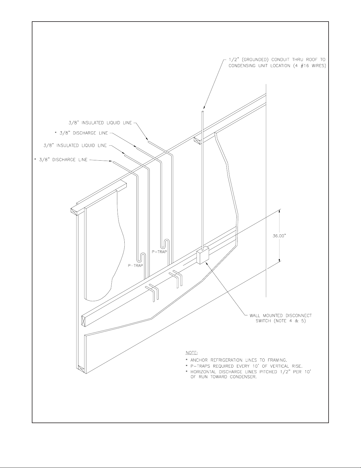
Figure 5
Remote Condenser
6
 Loading...