

Stoelting 100CA Installation Manual

Model 100FA / 100CA / 2217GA
OPERATORS MANUAL
Manual No. 513653 Mar. 2010


This manual provides basic information about the machine. Instructions and suggestions are
given covering its operation and care.
The illustrations and specifi cations are not binding in detail. We reserve the right to make
changes to the machine without notice, and without incurring any obligation to modify or provide new parts for machines built prior to date of change.
DO NOT ATTEMPT to operate the machine until instructions and safety precautions in this
manual are read completely and are thoroughly understood. If problems develop or questions
arise in connection with installation, operation, or servicing of the machine, contact Stoelting.
stoeltingfoodservice.com
Stoelting Foodservice Equipment
502 Highway 67
Kiel, WI 53042-1600
U.S.A.
Main Tel: 800.558.5807
Fax: 920.894.7029
Customer Service: 888.429.5920
Fax: 800.545.0662
Email: foodservice@stoelting.com
© 2014 PW Stoelting, LLC
A Few Words About Safety
Safety Information
Read and understand the entire manual before
operating or maintaining Stoelting equipment.
This manual provides the operator with information
for the safe operation and maintenance of Stoelting
equipment. As with any machine, there are hazards
associated with their operation. For this reason safety
is emphasized throughout the manual. To highlight
specifi c safety information, the following safety defi ni-
tions are provided to assist the reader.
The purpose of safety symbols is to attract your attention to possible dangers. The safety symbols, and
their explanations, deserve your careful attention
and understanding. The safety warnings do not by
themselves eliminate any danger. The instructions
or warnings they give are not substitutes for proper
accident prevention measures.
If you need to replace a part, use genuine Stoelting
parts with the correct part number or an equivalent
part. We strongly recommend that you do not use
replacement parts of inferior quality.
Safety Alert Symbol:
This symbol Indicates danger, warning or caution.
Attention is required in order to avoid serious personal injury. The message that follows the symbol
contains important information about safety.
Signal Word:
Signal words are distinctive words used throughout
this manual that alert the reader to the existence and
relative degree of a hazard.
WARNING
The signal word “WARNING” indicates a potentially
hazardous situation, which, if not avoided, may result
in death or serious injury and equipment/property
damage.
CAUTION
The signal word “CAUTION” indicates a potentially
hazardous situation, which, if not avoided, may result
in minor or moderate injury and equipment/property
damage.
CAUTION
The signal word “CAUTION” not preceded by the
safety alert symbol indicates a potentially hazardous
situation, which, if not avoided, may result in equipment/property damage.
NOTE (or NOTICE)
The signal word “NOTICE” indicates information or
procedures that relate directly or indirectly to the
safety of personnel or equipment/property.

TABLE OF CONTENTS
SECTION DESCRIPTION PAGE
SECTION 1 INTRODUCTION .............................................................................................................. 1
1.1 Description ...................................................................................................................... 1
1.2 Specifications.................................................................................................................. 1
SECTION 2 INSTALLATION INSTRUCTIONS...................................................................................... 3
2.1 Safety Precautions.......................................................................................................... 3
2.2 Shipment and Transit ...................................................................................................... 3
2.3 Freezer Installation.......................................................................................................... 3
2.4 Adjusting Cup Dispensers ............................................................................................... 7
SECTION 3 INITIAL SET-UP AND OPERATION ................................................................................. 9
3.1 Operator's Safety Precautions ......................................................................................... 9
3.2 Operating Controls and Indicators.................................................................................... 9
3.3 Draining the Freezer For Disassembling and Cleaning..................................................... 10
3.4 Disassembly and Cleaning of Freezer Parts .................................................................... 10
3.5 Sanitizing The Freezers and Freezer Parts...................................................................... 15
3.6 Assembly of Freezer ....................................................................................................... 15
3.7 Mix Information................................................................................................................ 17
3.8 Freeze Down and Operation ............................................................................................ 17
3.9 Dispensing Product ......................................................................................................... 17
3.10 Routine Cleaning ............................................................................................................. 17
3.11 Preventative Maintenance ................................................................................................ 17
3.12 Extended Storage............................................................................................................ 18
SECTION 4 DECALS AND TAGS....................................................................................................... 21
4.1 How to Order Decals and Tags........................................................................................ 21

LIST OF ILLUSTRATIONS
Figure Illustration Page
1 Model 100C - Front.................................................................................................................... 2
2 Model 100C - Side..................................................................................................................... 2
3 Model 100F/2217G - Front......................................................................................................... 2
4 Model 100F/2217G - Side.......................................................................................................... 2
5 Adjustable Leg .......................................................................................................................... 3
6 Warning Label Locations - 100C ................................................................................................ 4
7 Warning Label Locations - 100F/2217G ..................................................................................... 5
8 Space & Ventilation Requirements ............................................................................................ 6
9 Electrical Plug........................................................................................................................... 6
10 Installing Sani-tray and Cover .................................................................................................... 6
1 1 Adjusting Cup Dispensers ......................................................................................................... 7
12 Operating Controls..................................................................................................................... 9
13 Remove Sani-tray and Cover...................................................................................................... 11
14 Draining Product ........................................................................................................................ 11
15 Removing Spigot Assembly....................................................................................................... 12
16 Removing Spigot O-RIng from Spigot Body................................................................................ 12
1 7 Cut-away View of Spigot Assembly ........................................................................................... 12
18 Removing Drive Cap and O-Ring ................................................................................................ 13
19 Removing Sealer Ring ............................................................................................................... 13
2 0 Removing Agitator Assembly and Lower Bushing ...................................................................... 13
21 Removing Divider Plate from Agitator Fingers............................................................................. 14
22 Removing Drive Shaft ................................................................................................................. 14
2 3 Exploded View of Divider plate and Agitator Assembly .............................................................. 14
24 Lubricating Drive Shaft ............................................................................................................... 15
2 5 Installing Divider Plate and Agitator Assembly........................................................................... 16
2 6 Proper Installation of Sealer Ring............................................................................................... 16
2 7 Correct and Incorrect Alignment of Vertical Center Post Guide Hole .......................................... 16
2 8 External Parts To Be Cleaned ................................................................................................... 19
SECTION 1
INTRODUCTION
1.1 DESCRIPTION
Models 100CA, 100FA, and 2217GA freezers are gravity
fed. The freezers are equipped with fully automatic controls
to provide a uniform product. The freezers are designed to
operate with Slush Puppie neutral bases and concentrated
flavors.
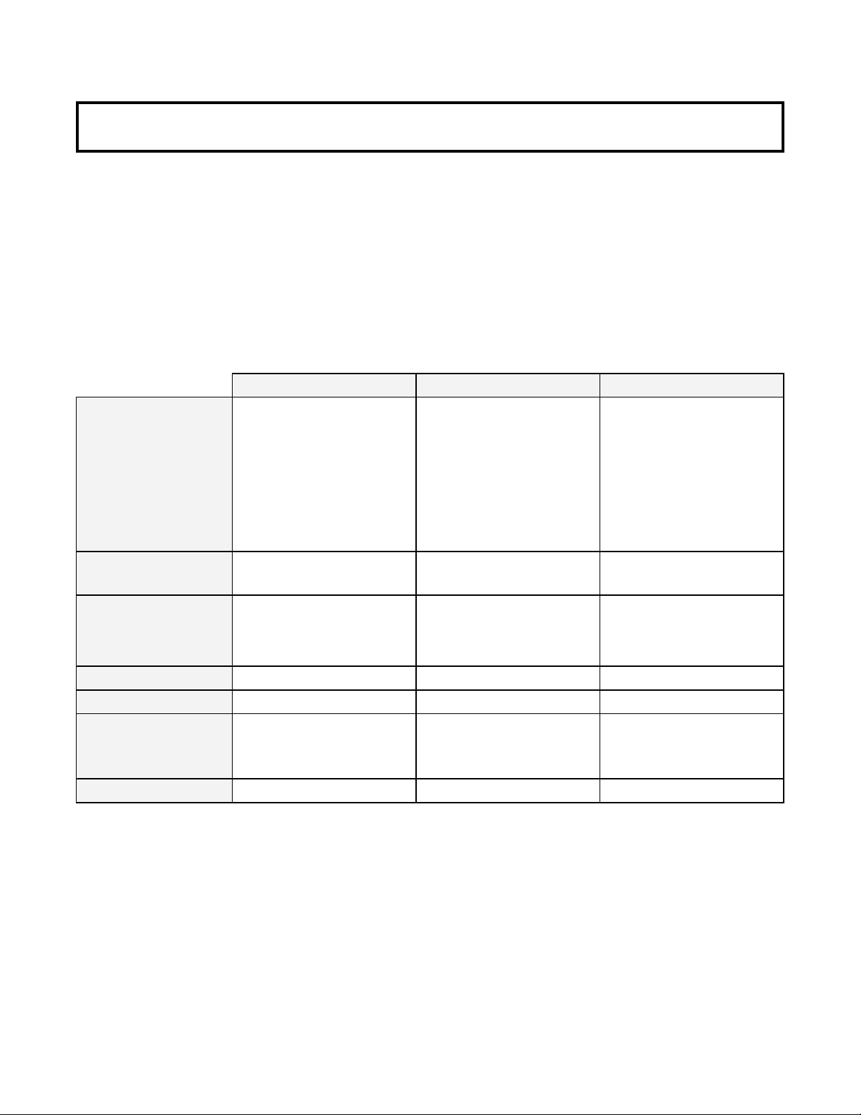
1.2 SPECIFICATIONS
This manual is designed to assist qualified service
personnel and operators in the installation, operation
and maintenance of the Models 100CA, 100FA, and
2217GA freezers.
Dimensions
width
height
depth
Weight
Electrical
running amps
connection type
Compressor
Drive Moto r
Cooling
Hopper Vol u m e
Model 100CA
Ma ch i n e w i th crate Ma chine wi th crate Ma ch i ne with cra te
15'' (38,1 c m ) 28'' (71,1 cm) 15'' (38,1 cm) 17'' (43,2 cm ) 15'' (38,1 c m ) 17'' (43,2 c m )
32'' (81,3 c m )
29-1/2'' (74,9
cm)
142 lbs (64, 4
kg)
40-1/4'' (102,2
cm)
35-1/2'' (90,2
cm)
200 lbs (90,7
kg)
Model 100FA Model 2217GA
58'' (147,3 c m ) 66'' (167,6 cm) 58'' (147, 3 cm ) 66'' (167,6 cm )
15'' (38,1 cm ) 21'' (53, 3 c m ) 15'' (38,1 cm ) 21'' (53,3 cm)
140 lbs (63,5
kg)
165 lbs (74,8
kg)
160 lbs (72, 5
kg)
185 lbs (83,9
kg)
1 Phase, 115 VAC, 60Hz1 Phase, 115 VAC, 60Hz 1 Phase, 115 VAC, 60Hz
approximate l y 7A
NEM A5- 15P included
2,250 Bt u/hr
1/12 hp
Air cool ed un its r equire 6"
(15, 2 cm ) air spa ce an
sides and back
10 gal l o n (37 , 85 liter s)
approximat el y 7A
NEM A5-15 P inc l uded NEMA5- 15P in cl uded
2,250 Btu/h r 2,250 Bt u/hr
1/12 h p
Air cool ed un it s r eq uire 6"
(15,2 cm) air space at
front an d back.
10 gallon ( 37, 85 l it er s)
approximately 9A
1/12 hp
Air cooled un its require 6"
(15, 2 cm ) air spa ce at
fr ont an d back .
10 gal l on (37,85 liters )
1
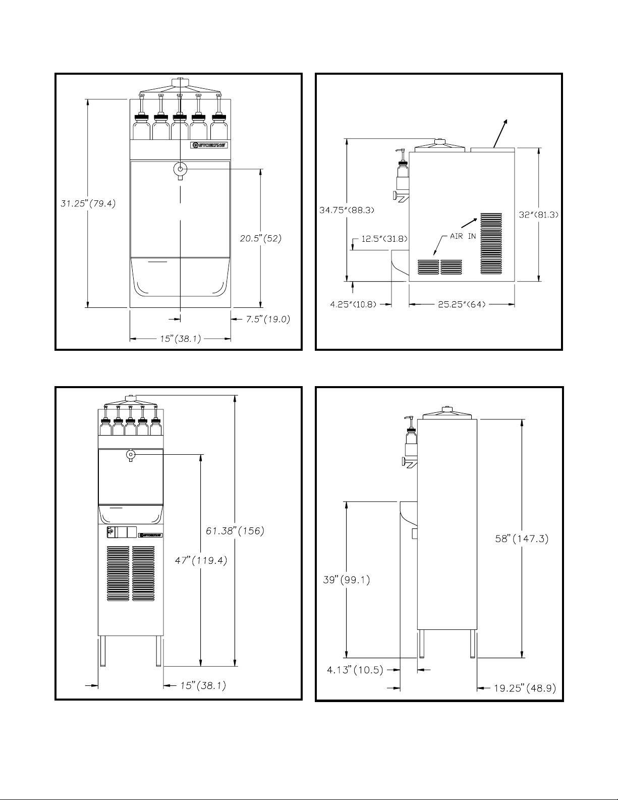
AIR OUT
Figure 1
Model 100CA - Front
Figure 2
Model 100CA - Side
Figure 3
Model 100FA/2217GA - Front
NOTE: Figures in parenthesis are in centimeters.
Figure 4
Model 100FA/2217GA - Side
2
SECTION 2
INSTALLATION INSTRUCTIONS
2.1 SAFETY PRECAUTIONS
Do not attempt to operate the freezer until the safety
precautions and operating instructions in this manual are
read and completely understood.
Take notice of all warning labels on the freezer (Figures 6
& 7). The labels have been put there to help maintain a safe
working environment. The labels have been designed to
withstand washing and cleaning. All labels must remain
legible for the life of the freezer. Labels should be checked
periodically to be sure they can be recognized as warning
labels.
If danger, warning, or caution labels are needed, indicate
the part number, type of label, location of label, and
quantity required along with your address and advise your
distributor.
2.2 SHIPMENT AND TRANSIT
The freezer has been assembled, operated and
inspected at the factory. Upon arrival at the final destination, the complete freezer must be checked for any
damage which may have occurred during transit.
With the method of packaging used, the freezer should
arrive in excellent condition. THE CARRIER IS
RESPONSIBLE FOR ALL DAMAGE IN TRANSIT,
WHETHER VISIBLE OR CONCEALED.
NOTICE
Accurate leveling is necessary to insure proper operation
and correct drainage of freezer barrel.
W ARNING
Lifting hazard
Do not attempt to lift freezer manually . Use proper lifting equipment such as a forklift, lift table, or pallet
jack, with lifting device positioned beneath the freezer’s
base. Ensure that personnel remain clear of suspended
load. Failure to do so may result in personal injury
and/or damage to the freezer that will void any factory
warranties.
Do not pay the freight bill until the freezer has been
checked for damage. Have the carrier note any visible
damage on the freight bill. If concealed damage and/or
shortage is found later, advise the carrier within 10 days
and request inspection. The customer must place claim
for damages and/or shortages in shipment with the carrier.
2.3 FREEZER INSTALLATION
Installation of the freezer involves moving the freezer close
to its permanent location, removing all crating, setting in
place, assembling parts, and cleaning.
A. Uncrate the freezer.
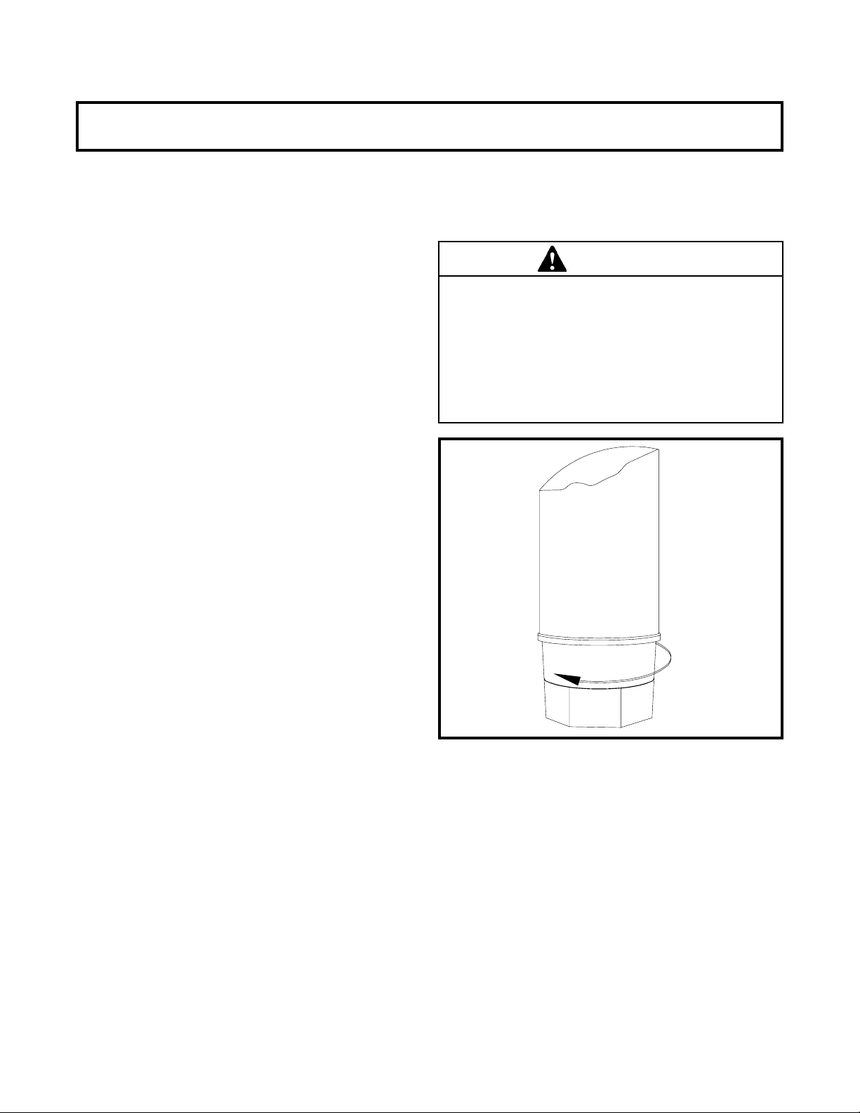
B. The floor model freezers must be placed in a
solid level position. To level the freezer, turn the bottom
part of each leg in or out. Place a level on top of the
hopper, with the cover removed, to check whether or not
the freezer islevel (Fig. 5).
Figure 5
Adjustable Leg
C. The counter model freezer must be placed on a solid
level surface. Place the rubber pad furnished under the
freezer to create a seal to that surface. The counter
model freezer is air-cooled and discharges at the top.
AL LOUVERED PANELS MUST have 3" of clearance
on sides of unit, 10" of clearance at the top, and 1"
clearance at rear of unit for proper cooling.
3
 Loading...