

Page 1

Models 100F & C, 2217G
SERVICE MANUAL
Manual No. 513554
Page 2

Page 3

SERVICE MANUAL
MODELS 100 F & C AND 2217G SLUSH FREEZERS
This manual provides basic information about the freezer. Instructions and suggestions are given
covering its operation and care.
The illustrations and specifications are not binding in detail. We reserve the right to make
changes to the freezer without notice, and without incurring any obligation to modify or provide
new parts for freezers built prior to date of change.
DO NOT ATTEMPT to service or operate the freezer until instructions and safety precautions in
this manual are read completely and are thoroughly understood. If problems develop or questions
arise in connection with installation, operation or servicing of the freezer, contact your distributor.
STOELTING, LLC Tele: 920-894-2293
502 HWY. 67
KIEL, WI 53042-1600 Fax: 920-894-7029
Page 4

Page 5

TABLE OF CONTENTS
SECTION DESCRIPTION PAGE
SECTION 1 INTRODUCTION .............................................................................................................. 1
1.1 Descriptions .................................................................................................................... 1
1.2 Specifications.................................................................................................................. 1
SECTION 2 INSTALLATION INSTRUCTIONS...................................................................................... 3
2.1 Safety Precautions.......................................................................................................... 3
2.2 Shipment and Transit ...................................................................................................... 3
2.3 Freezer Installation .......................................................................................................... 3
2.4 Adjusting Cup Dispensers ............................................................................................... 7
SECTION 3 INITIAL SET-UP AND OPERATION ................................................................................. 9
3.1 Operator's Safety Precautions ......................................................................................... 9
3.2 Operating Controls and Indicators.................................................................................... 9
3.3 Draining the Freezer For Disassembling and Cleaning..................................................... 10
3.4 Disassembly and Cleaning of Freezer Parts .................................................................... 10
3.5 Sanitizing The Freezers and Freezer Parts...................................................................... 15
3.6 Assembly of Freezer ....................................................................................................... 15
3.7 Mix Information................................................................................................................ 17
3.8 Freeze Down and Operation ............................................................................................ 17
3.9 Dispensing Product ......................................................................................................... 17
3.10 Routine Cleaning ............................................................................................................. 17
3.11 Preventative Maintenance ................................................................................................ 17
3.12 Extended Storage............................................................................................................ 18
SECTION 4 DECALS AND TAGS....................................................................................................... 21
4.1 How to Order Decals and Tags........................................................................................ 21
SECTION 5 REFRIGERATION COMPONENTS AND ADJUSTMENTS ............................................... 23
5.1 Refrigeration System ....................................................................................................... 23
5.2 Compressor..................................................................................................................... 23
5.3 Condenser ....................................................................................................................... 23
SECTION 6 ELECTRICAL SYSTEM OPERATION AND ADJUSTMENTS ........................................... 27
6.1 24 Hour Timer.................................................................................................................. 27
6.2 Electronic Torque Control ................................................................................................ 27
SECTION 7 MAJOR COMPONENT REMOVAL AND INSTALLATION................................................. 29
7.1 Introduction ..................................................................................................................... 29
7.2 Condenser Fan Removal.................................................................................................. 29
7.3 Drive Motor Removal ........................................................................................................................... 29
7.4 Compressor Removal ...................................................................................................... 29
7.5 Compressor Installation ................................................................................................... 30
7.6 Drive Motor Installation .................................................................................................... 31
7.7 Condenser Fan Installation .............................................................................................. 31
SECTION 8 TROUBLESHOOTING ..................................................................................................... 33
8.1 Compressor Run Capacitor Open, Shorted or Blown........................................................ 34
8.2 Compressor Relay Defective or Burned Out ..................................................................... 34
8.3 Compressor Starts and Runs, But Short Cycles On Overload Protector .......................... 34
8.4 Compressor Runs Continuously ...................................................................................... 34
8.5 Unit Noisy ....................................................................................................................... 34
8.6 Compressor Will Not Start............................................................................................... 34
8.7 Compressor Will Not Start - Hums But Trips On Overload Protector................................ 35
8.8 Compressor Starts, But Does Not Switch Off of Start Winding ........................................ 35
Page 6

TABLE OF CONTENTS
8.9 Compressor Start Capacitor Open, Shorted or Blown ...................................................... 35
8.10 Freezer Will Not Start...................................................................................................... 35
8.11 Drive Motor Overload Trips (Freezer Shuts Down When Running) .................................... 35
8.12 Compressor Will Not Run, But Drive Motor Runs ............................................................. 35
8.13 Product Dispenses Incorrectly......................................................................................... 35
8.14 Product is Too Thin ......................................................................................................... 36
8.15 Agitator Does Not Rotate................................................................................................. 36
8.16 No Ice Crystals On Initial Freeze Down ........................................................................... 36
8.17 Excessive Ice Crystals Above Divider Plate ..................................................................... 36
8.18 Spigot Leaking or Stuck .................................................................................................. 36
SECTION 9 REPLACEMENT PARTS AND REFERENCE DRAWINGS .............................................. 37
9.1 How to Order Parts.......................................................................................................... 37
9.2 Spigot Assembly Parts.................................................................................................... 37
9.3 Model 100C Parts List..................................................................................................... 39
9.4 Model 100F Parts List ..................................................................................................... 41
9.5 Model 2217G Parts List................................................................................................... 43
Page 7

LIST OF ILLUSTRATIONS
Figure Title Page
1 Model 100C - Front......................................................................................................................... 2
2 Model 100C - Side.......................................................................................................................... 2
3 Model 100F/2217G - Front.............................................................................................................. 2
4 Model 100F/2217G - Side............................................................................................................... 2
5 Adjustable Leg ............................................................................................................................... 3
6 Warning Label Locations - 100C..................................................................................................... 4
7 Warning Label Locations - 100F/2217G.......................................................................................... 5
8 Space & Ventilation Requirements ................................................................................................. 6
9 Electrical Plug................................................................................................................................ 6
10 Installing Sani-tray and Cover ......................................................................................................... 6
11 Adjusting Cup Dispensers .............................................................................................................. 7
12 Operating Controls ......................................................................................................................... 9
13 Remove Sani-tray and Cover........................................................................................................... 11
14 Draining Product............................................................................................................................. 11
15 Removing Spigot Assembly............................................................................................................ 12
16 Removing Spigot O-Ring from Spigot Body..................................................................................... 12
17 Cut-away View of Spigot Assembly ................................................................................................ 12
18 Removing Drive Cap and O-Ring ..................................................................................................... 13
19 Removing Sealer Ring .................................................................................................................... 13
20 Removing Agitator Assembly and Lower Bushing ........................................................................... 13
21 Removing Divider Plate from Agitator Fingers ................................................................................. 14
22 Removing Drive Shaft...................................................................................................................... 14
23 Exploded View of Divider plate and Agitator Assembly ................................................................... 14
24 Lubricating Drive Shaft.................................................................................................................... 15
25 Installing Divider Plate and Agitator Assembly................................................................................16
26 Proper Installation of Sealer Ring.................................................................................................... 16
27 Correct and Incorrect Alignment of Vertical Center Post Guide Hole............................................... 16
28 External Parts To Be Cleaned ........................................................................................................ 19
Page 8

LIST OF ILLUSTRATIONS
30 Removing Compressor Terminal Cover............................................................................................ 23
31 Check Winding............................................................................................................................... 23
32 Check Winding To Ground.............................................................................................................. 23
33 Check Condenser........................................................................................................................... 24
34 Remove Cap ................................................................................................................................... 24
35 Install Gauge .................................................................................................................................. 25
36 Adjust A.X.V. ................................................................................................................................. 25
37 Filter Drier Replacement................................................................................................................. 26
38 Torque Control ................................................................................................................................27
39 Tension Spring ............................................................................................................................... 27
40 Removing Torque Control ................................................................................................................ 28
41 Fan Removal .................................................................................................................................. 29
42 Disconnect Wire............................................................................................................................. 29
43 Drive Motor Removal....................................................................................................................... 29
44 Compressor Removal ..................................................................................................................... 30
45 Install Compressor ......................................................................................................................... 30
46 Remove Filter Drier......................................................................................................................... 31
47 Tension Spring ............................................................................................................................... 31
48 Fan Installation............................................................................................................................... 31
49 Exploded View of Spigot Assembly ................................................................................................ 37
50 Model 100C Exploded View............................................................................................................ 38
51 Model 100F Exploded View ............................................................................................................ 40
52 Model 2217G Exploded View.......................................................................................................... 42
Page 9
SECTION 1
INTRODUCTION
1.1 DESCRIPTION
Models 100C, 100F, and 2217G freezers are gravity fed.
The freezers are equipped with fully automatic controls to
provide a uniform product. The freezers are designed to
operate with most neutral bases and concentrated flavors.
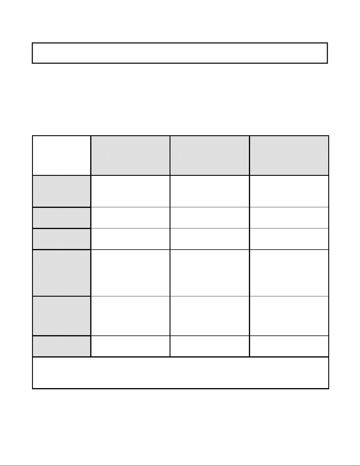
1.2 SPECIFICATIONS
This manual is designed to assist qualified service personnel and operators in the installation, operation and maintenance of the Models 100C, 100F, and 2217G freezers.
DIMENSIONS
WEIGHT
ELECTRICA L
COMPRESSOR
COOLING
100C COUNTER
MODEL FREEZER
widt h: 15" (38.1 cm)
depth: 29.5" (74.8 cm)
heig ht : 34. 75 " (88 . 3 cm)
130 lbs. (58.9 kg) 140 lbs. (63.5 kg) 140 lbs. (63.5 kg)
1 Phase, 115 VA C*
1/12 HP Drive Motor
2500 BTUH**
(frozen product output)
- Approx. 11 total running
amps. Use 15 A mp circuit breaker
Air cooled requires minimum
3" (7.6 cm) air clearance on
sides and 1" (2.5 cm) at rear
of unit.
100F FLOOR
MODEL FREEZER
width: 15" (38.1 cm)
depth: 19.25" (48.9 cm)
height: 61.38" (156 cm)
1 Phase, 115 VAC*
1/12 HP Dri v e M ot or
2500 BTUH**
(frozen product output)
- Approx. 11 total running
amps. Use 15 Amp circui t breaker
Requires unobstructed front
and 6" minimum (15.2 cm)
clearanc e at ba ck of uni t . No
clearance need ed on side of
unit.
2217G FLOOR
MODEL FREEZER
widt h: 15" (38.1 cm)
depth: 19.25" (48.9 cm)
height: 61.38" (156 cm)
1 Phase, 115 VA C*
1/12 HP Drive Motor
5200 BTUH**
(frozen product output)
- Approx. 9 total running
amps. Use 15 Amp cirucit breaker
Requires unobstructed front
and 6" mini mum (15.2 cm)
clearance at back of unit. No
clearance needed on side of
unit.
HOPPER
10 gallons (37.9 liters) 10 gallons (37. 9 li t er s ) 10 gallons (37.9 liters)
* A transformer is required if voltage is over 126.5 volts or under 103 volts.
** Under normal operating conditions.
1
Page 10
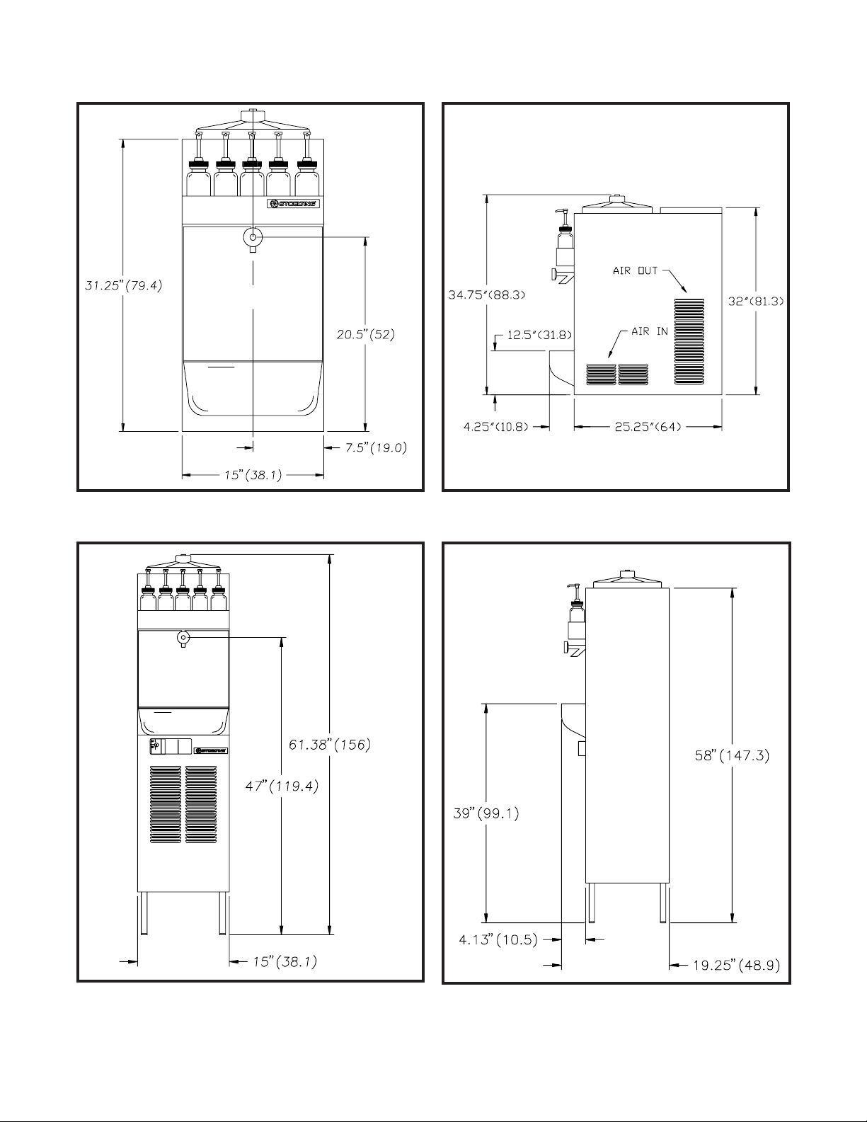
Figure 1
Model 100C - Front
Figure 2
Model 100C - Side
Figure 3
Model 100F/2217G - Front
NOTE: Figures in parenthesis are in centimeters.
Figure 4
Model 100F/2217G - Side
2
Page 11
SECTION 2
INSTALLATION INSTRUCTIONS
2.1 SAFETY PRECAUTIONS
Do not attempt to operate the freezer until the safety
precautions and operating instructions in this manual are
read and completely understood.
Take notice of all warning labels on the freezer (Figures 6
& 7). The labels have been put there to help maintain a safe
working environment. The labels have been designed to
withstand washing and cleaning. All labels must remain
legible for the life of the freezer. Labels should be checked
periodically to be sure they can be recognized as warning
labels.
If danger, warning, or caution labels are needed, indicate
the part number, type of label, location of label, and
quantity required along with your address and advise your
distributor.
2.2 SHIPMENT AND TRANSIT
The freezer has been assembled, operated and
inspected at the factory. Upon arrival at the final destination, the complete freezer must be checked for any
damage which may have occurred during transit.
With the method of packaging used, the freezer should
arrive in excellent condition. THE CARRIER IS
RESPONSIBLE FOR ALL DAMAGE IN TRANSIT,
WHETHER VISIBLE OR CONCEALED.
NOTE
Accurate leveling is necessary for correct
drainage of freezer barrel and to insure proper
operation.
C. The counter model freezer must be placed on a solid
level surface. Place the rubber pad furnished under the
freezer to create a seal to that surface. The counter
model freezer is air-cooled and discharges at the top.
AL LOUVERED PANELS MUST have 3" of clearance
on sides of unit, 10" of clearance at the top, and 1"
clearance at rear of unit for proper cooling.
Do not pay the freight bill until the freezer has been
checked for damage. Have the carrier note any visible
damage on the freight bill. If concealed damage and/or
shortage is found later, advise the carrier within 10 days
and request inspection. The customer must place claim
for damages and/or shortages in shipment with the carrier.
2.3 FREEZER INSTALLATION
Installation of the freezer involves moving the freezer close
to its permanent location, removing all crating, setting in
place, assembling parts, and cleaning.
A. Uncrate the freezer.
B. The floor model freezers must be placed in a
solid level position. To level the freezer, turn the bottom
part of each leg in or out. Place a level on top of the
hopper, with the cover removed, to check whether or not
the freezer islevel (Fig. 5).
Figure 5
Adjustable Leg
3
Page 12
IMPORTANT NOTICE TO OPERATOR
BEFORE INSTALLING EQUIPMENT, READ THE OWNER'S MANUAL CAREFULLY. TAKE NOTE OF ALL INSTRUCTIONS AND CAUTION
DECALS ON THIS EQUIPMENT.
GO OVER THE MANUAL THOROUGHLY AND POINT OUT ALL DECALS TO YOUR EMPLOYEES, SO THEY UNDERSTAND HOW TO SAFELY
OPERATE THIS EQUIPMENT.
DO NOT REMOVE, DEFACE, OR PAINT OVER ANY DECALS. THEY ARE THERE FOR YOUR SAFETY.
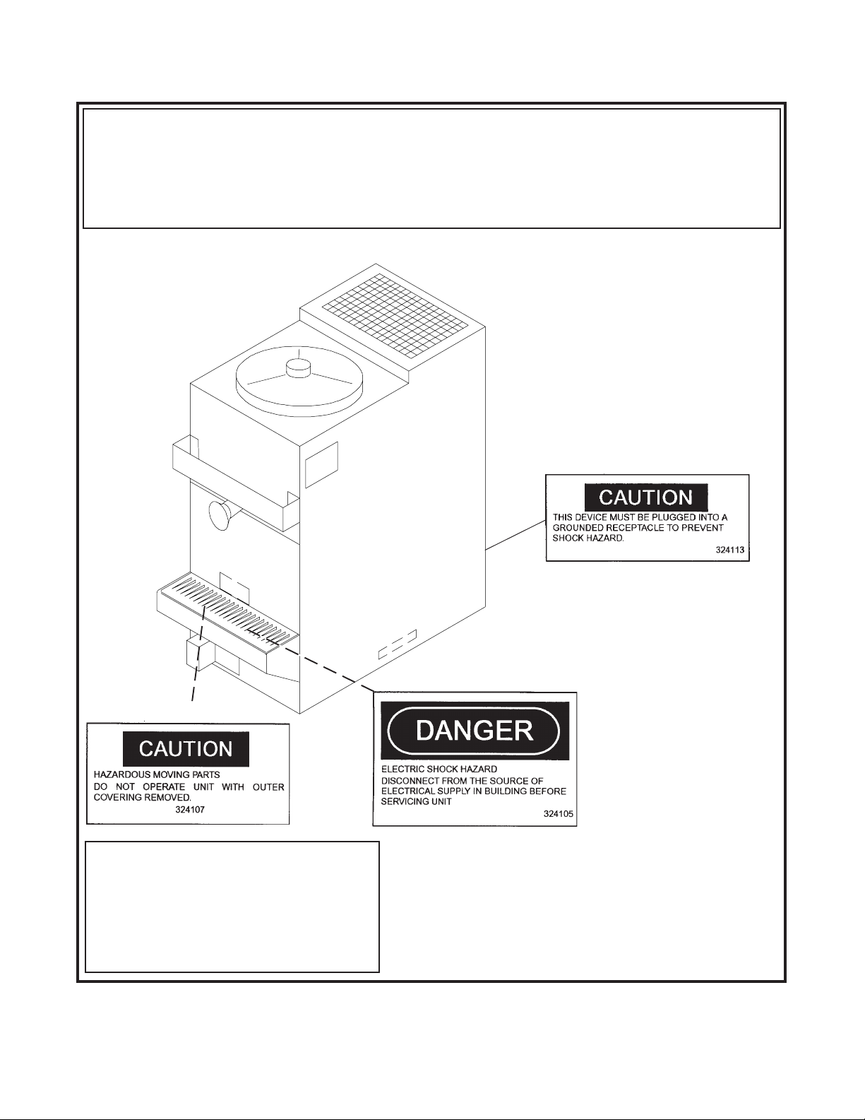
(Behind Sani-tray)
CAUTION
THIS DEVICE MUST BE PLUGGED INTO A PROPERLY GROUNDED
RECEPTACLE TO PREVENT ELECTRICAL SHOCK HAZARD.
TAMPERING WITH THE PLUG OR USING VOLTAGES OTHER THAN
THE SPECIFICATIONS ON I.D. PLATE WILL VOID YOUR WARRANTY.
REFER TO OWNER'S MANUAL FOR INSTALLATION
INSTRUCTIONS.
723529
Warning Label Locations - 100C
(Behind Sani-tray)
Figure 6
4
Page 13
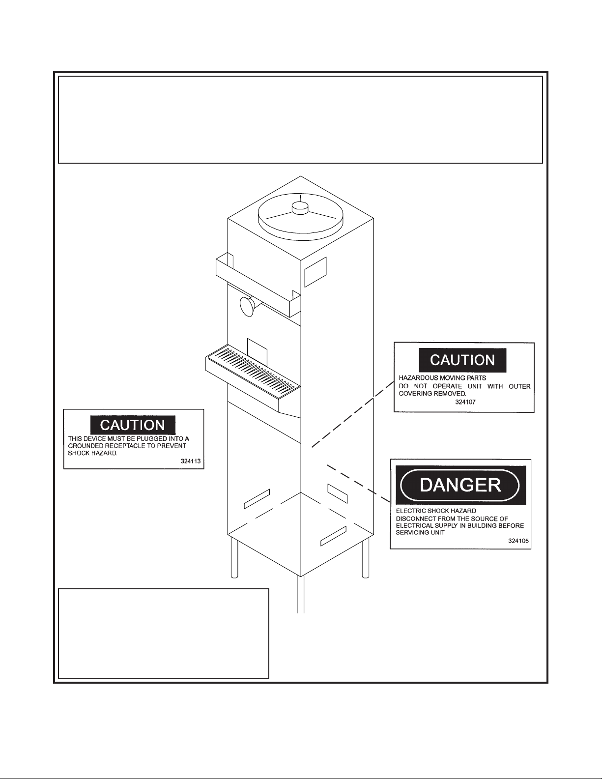
IMPORTANT NOTICE TO OPERATOR
BEFORE INSTALLING EQUIPMENT, READ THE OWNER'S MANUAL CAREFULLY. TAKE NOTE OF ALL INSTRUCTIONS AND CAUTION
DECALS ON THIS EQUIPMENT.
GO OVER THE MANUAL THOROUGHLY AND POINT OUT ALL DECALS TO YOUR EMPLOYEES, SO THEY UNDERSTAND HOW TO SAFELY
OPERATE THIS EQUIPMENT.
DO NOT REMOVE, DEFACE, OR PAINT OVER ANY DECALS. THEY ARE THERE FOR YOUR SAFETY.
(Affixed to condenser shroud)
THIS DEVICE MUST BE PLUGGED INTO A PROPERLY GROUNDED
RECEPTACLE TO PREVENT ELECTRICAL SHOCK HAZARD.
TAMPERING WITH THE PLUG OR USING VOLTAGES OTHER THAN THE
SPECIFICATIONS ON I.D. PLATE WILL VOID YOUR WARRANTY.
REFER TO OWNER'S MANUAL FOR INSTALLATION
INSTRUCTIONS.
723529
Warning Label Locations - 100F/2217G
CAUTION
Figure 7
5
(Affixed to condenser shroud)
Page 14
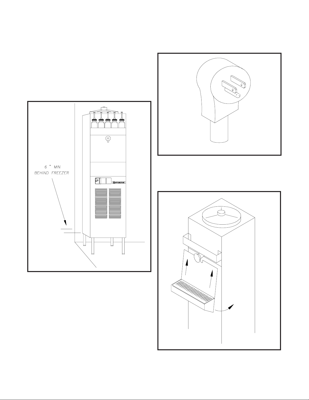
D. The floor model freezers are equipped with air-cooled
condensers and require correct ventilation. The front of
the freezer is the air intake and must be unobstructed.
Air discharges out of the rear of the unit. Do not obstruct
the discharge. Allow a 6" (15.2 cm) clearance behind
the unit (Fig. 8).
CAUTION
FAILURE TO PROVIDE ADEQUATE VENTILATION WILL
VOID WARRANTY!
CAUTION
DO NOT ALTER OR DEFORM PLUG IN ANY WAY!
Figure 9
Electrical Plug
G. Install the sani-tray, cover and miscellaneous parts
on the freezer (Fig. 10).
Figure 8
Space and Ventilation Requirements
E. Place the ON-OFF-STIR ONLY toggle switch in the
OFF position. This switch is located on the lower left of
the freezer, under the drip tray and cover.
F. Connect the power cord. The plug is designed for 115
volt/15 amp duty. The unit must be connected to a
properly grounded receptacle. The electrical cord
furnished as part of the freezer has a three prong
grounding type plug (Fig.9). The use of an extension
cord is not recommended. If one must be used, use one
with a wire, size 12 gauge or heavier, with a ground. Do
not use an adaptor to avoid grounding equipment.
Figure 10
Installing Sani-tray and Cover
6
Page 15

2.4 ADJUSTING CUP DISPENSERS
To adjust the cup dispensers, install the size cup desired
into the dispenser and turn the wing nuts on the dispenser
mounting bracket until enough tension is applied to the rim
of the cup to keep it from dropping out (Fig. 11). Do not overtighten the wing nuts.
WING NUTS
Figure 11
Adjusting Cup Dispensers
7
Page 16

8
Page 17

SECTION 3
INITIAL SET-UP AND OPERATION
3.1 OPERATOR'S SAFETY PRECAUTIONS
A. Know the freezer. Read and understand the Operating
Instructions.
B. Notice all warning labels on the freezer.
C. Wear proper clothing. Avoid loose fitting garments,
and remove watches, rings or jewelry which could
cause a serious accident.
D. Maintain a clean work area. Avoid accidents by
cleaning up the area and keeping it clean.
E. Stay alert at all times. Know which switch, push-
button or control you are about to use and what
effect it is going to have.
F. Disconnect electrical cord for maintenance. Never
attempt to repair or perform maintenance on the
freezer until the main electrical power has been
disconnected.
G. Do not operate under unsafe operating conditions.
Never operate the freezer if unusual or excessive
noise or vibration occurs.
3.2 OPERATING CONTROLS AND INDICATORS
Before operating the freezer, it is required that the operator
know the function of each operating control and indicator.
Refer to Figure 12 for the locations of the operating controls
and indicators.
WARNING
THE STIRRING ONLY-OFF-STIRRING & FREEZING
SWITCH MUST BE PLACED IN THE OFF POSITION
WHEN DISASSEMBLING FOR CLEANING OR SERVICING. THE FREEZER MUST BE DISCONNECTED FROM
ELECTRICAL SUPPLY BEFORE REMOVING ANY ACCESS PANELS. ONLY A QUALIFIED SERVICE TECHNICIAN MAY REMOVE ACCESS PANELS.
STIRRING ONLY-OFFSTIRRING & FREEZING
TOGGLE SWITCH
RESET
SWITCH
SEVEN DAY TIMER
Figure 12
Operating Controls
9
HIGH PRESSURE MANUAL
RESET SWITCH
Page 18

A. STIRRING ONLY-OFF-STIRRING & FREEZING
SWITCH
The STIRRING ONLY-OFF-STIRRING & FREEZING switch is a three-position toggle switch used to
control the operation of the refrigeration system and
agitator. When the switch is placed in the STIRRING ONLY position, the refrigeration system will
be off and the agitator will rotate for cleaning, or if
stirring is required when the store is closed. When the
switch is placed in the OFF position, the refrigeration
system and agitator will be off. The switch should be
placed in the STIRRING & FREEZING position for
normal operation.
B. RESET SWITCH
The reset switch is a two-position breaker switch. This
switch is used to protect the freezer from mechanical
damage. The switch must be in the NORMAL
OPERATING POSITION (up) before the freezer will
operate.
Any time a condition occurs which causes the
agitator drive motor to draw excessive current, the
reset switch will automatically switch to the
OVERLOAD CUT-OUT FREEZER NOT OPERATING position. This will shut down the freezing and
agitation action of the freezer to protect the agitator
drive motor from burning out.
Should the reset switch ever trip out, move
the STIRRING ONLY-OFF-STIRRING & FREEZING toggle switch to the STIRRING ONLY position.
Then move the reset switch back to NORMAL
OPERATING POSITION (up) and allow the freezer
to stir, without refrigeration, for five minutes. After
five minutes of stirring, return the STIRRING
ONLY-OFF-STIRRING & FREEZING switch to the
STIRRING & FREEZING position.
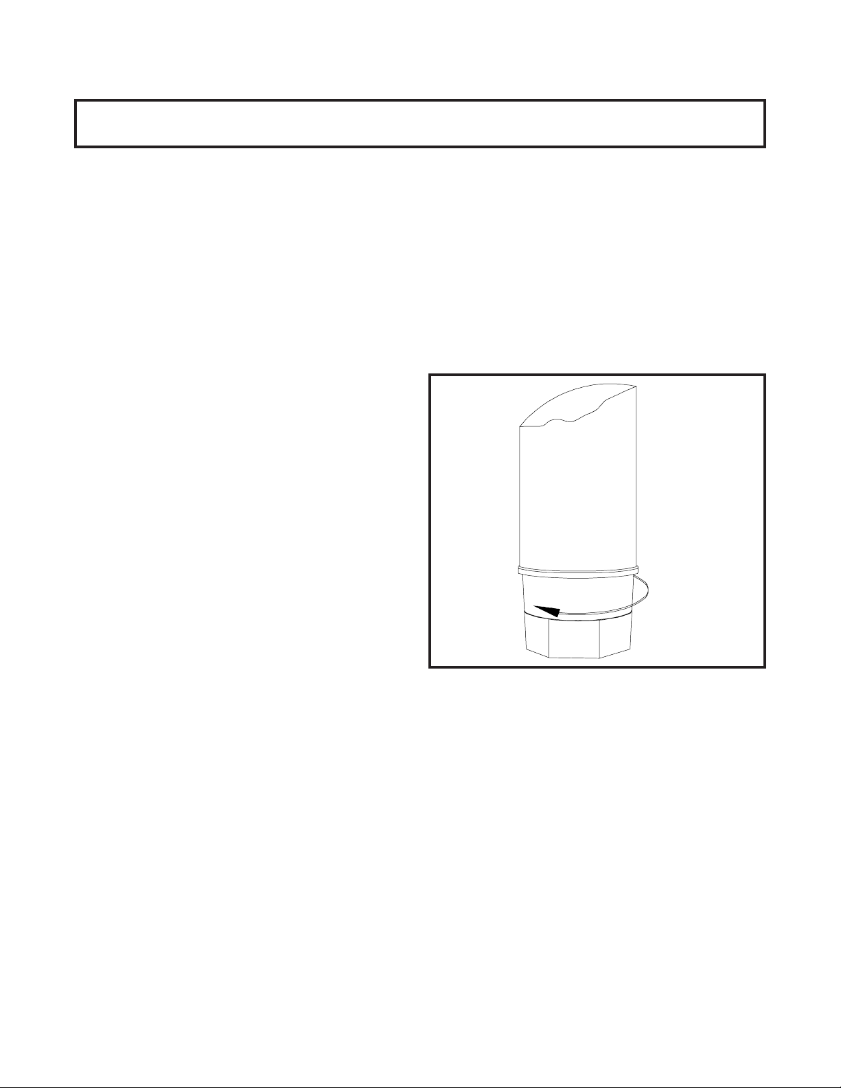
C. 24 HOUR TIMER
To program the timer, rotate program disc in the
direction of the arrows to align the correct day/time
with the time of day mark. Then pull out for Off time
or push in for On time. Each actuator is equivalent
to 15 minutes time. Check for AM/PM centered
between 12 and 12 on rotating disc. At a 6:00 setting the
indicator will point to AM or PM.
D. HIGH PRESSURE MANUAL RESET SWITCH
The HIGH PRESSURE MANUAL RESET SWITCH is a
safety switch designed to protect the compressor from
damage due to excessive head pressure. When tripped,
the lever will be out; push to reset.
E. SPIGOT ASSEMBLY
Dispensing of frozen mix is done by the SPIGOT
ASSEMBLY. By pulling the spigot plunger out, mix
in the form of ice crystals is dispensed through the
port on the bottom of the SPIGOT ASSEMBLY. To
stop dispensing, push the spigot plunger in.
F. FLAVOR BOTTLES
The FLAVOR BOTTLES are operated by a spring
loaded, push-button pump. By pushing down, 1/4
ounce (7.39 ml) of flavor is dispensed.
3.3 DRAINING THE FREEZER FOR DISASSEMBLING
AND CLEANING
After installation and initial set-up, the freezer exterior
must be cleaned and the freezer parts must be disassembled, cleaned and sanitized. Cleaning and sanitizing
MUST be done before the initial freeze down and operation.
Subsequent cleaning and sanitizing, after the freezer has
been operated and product has been dispensed, will
require the freezer to be completely drained of all unused
mix. Perform the following steps to drain the freezer of any
unused mix:
A. Set the STIRRING ONLY-OFF-STIRRING &
FREEZING switch to the STIRRING ONLY position
well in advance of cleaning and sanitizing to assure
complete defrosting and draining of the product
cylinder.
B. While the freezer is in the STIRRING ONLY mode,
remove the unused flavoring from the flavor bottles.
All unused flavoring should be poured into the
containers from which they came.
C. Remove the Sani-tray and cover by gently pushing
up to disengage from the support pins and pulling
out and down (Fig. 13).
D. With a bucket placed below the drain spigot, pull the
spigot to dispense (Fig. 14).
E. When liquid product is completely drained, empty
the bucket into the sink. Any remaining ice can be
removed by circulating warm water through barrel.
3.4 DISASSEMBLY AND CLEANING OF FREEZER
PARTS
CAUTION
PLACE THE ON-OFF-STIR ONLY SWITCH IN THE OFF
POSITION AND DISCONNECT THE FREEZER FROM
ELECTRICAL SUPPLY SOURCE BEFORE SERVICING
OR CLEANING.
10
Page 19

Figure 13
Removing Sani-tray and Cover
Inspection for worn or broken parts should be made during
every disassembly of the freezer for cleaning or other
purposes. All worn or broken parts should be replaced to
ensure safety to both the operator and the customer, and
to maintain good freezer performance as well as a quality
product.
NOTE
Frequency of cleaning MUST comply with local health
regulations.
The exterior of the freezer must be kept clean at all times
to preserve the luster of the stainless steel. A mild alkaline
cleanser is recommended. Use a soft cloth or sponge to
apply the cleanser.
NOTE
Do not use acid cleaners, strong caustic compounds or
abrasive materials to clean any plastic or stainless steel
parts of the freezer exterior.
A. Remove the dispensers from the side of the freezer
by pulling straight up. Clean the cup dispensers
and dispenser lids with a mild alkaline cleanser and
soft cloth or sponge.
B. Remove the sani-tray and insert by gently pushing
up to disengage from the support pins and pulling
out and down. Clean the sani-tray in the same
manner as the cup dispenses.
Figure 14
Draining Product
C. Remove the two-piece cover and mix level probe
assembly and clean.
D. Remove the flavor pumps from the bottles and
pump warm soapy water through them. Then clean
the bottles and pumps normally.
E. To remove the upper and lower spigot assemblies,
remove the retaining clip and pull the spigot assemblies straight out of the product outlet (Fig.15).
11
Page 20

È
È
Figure 15
Removing Spigot Assembly
O-RING
#624607
SPLASH DEFLECTOR
#1120918
SHAFT & PLUG
ASSEMBLY
#1147688
Figure 16
Removing Spigot O-Ring from Spigot body
SPRING
#694400
KNOB
#482024
RETAINER CAP
#232002
Figure 17
Cut-away View of Spigot Assembly
12
Page 21

1. With a clean, dry towel, wipe excess lubricant from the
spigot assembly and O-ring. Firmly grasp the spigot
assembly with both hands and squeeze the O-ring
upward (Fig 16). When a loop is formed, roll the O-ring
out of the groove toward the end of the spigot assembly.
(See Fig. 17 for a cutaway view of the spigot assembly.)
CAUTION
DO NOT USE ANY TYPE OF SHARP OBJECT TO
REMOVE ANY O-RINGS.
2. Place all loose parts in a pan or container and take
them to the wash sink, filled with warm, soapy water, for
cleaning.
3. Wash the product outlet with warm soapy water
using the brush provided.
G. For removal and disassembly of the divider plate
and agitator assembly, refer to the following steps:
WARNING
PLACE THE ON-OFF-STIR ONLY SWITCH IN THE OFF
POSITION AND DISCONNECT THE FREEZER
FROM ELECTRICAL SUPPLY SOURCE.
1. Remove the drive cap and O-ring from the agitator
tube (Fig.18).
Figure 19
Removing Sealer Ring
3. To remove the divider plate and agitator assembly, the
divider plate must be first rotated counterclockwise to
unlock and lift out of the product cylinder.
4. Once the divider plate and agitator assembly are
lifted off the vertical product cylinder center post and
out of the product cylinder, remove the divider plate
assembly and anti-lift disc. Remove the plastic
agitator bushing from the bottom of the product
cylinder center post by lifting up and out of the
product cylinder (Fig. 20). - Refer to Figure 23 for an
exploded view.
Figure 18
Removing Drive Cap and O-Ring
2. Remove the sealer ring by squeezing the looped
section and lifting out of the product cylinder (Fig. 19).
Figure 20
Removing Agitator Assembly and Lower Bushing
13
Page 22

5. Unscrew the divider plate from the agitator fingers
and remove (Fig.21).
Figure 21
Removing Divider Plate from Agitator Fingers
6. Remove the drive shaft by pulling straight up and
out of the vertical center post (Fig.22).
Figure 22
Removing Drive Shaft
Figure 23
Exploded View of Divider Plate and Agitator
Assembly
7. Place all loose parts in a pan or container and take
them to the wash sink, filled with warm, soapy
water, for cleaning.
CAUTION
DO NOT DAMAGE PARTS BY DROPPING OR ROUGH
HANDLING.
NOTE
Do not attempt to wash the inside of the vertical
product cylinder center post.
8. Wash the inside of the product cylinder with warm,
soapy water, using the brush provided.
14
Page 23

3.5 SANITIZING THE FREEZER AND FREEZER
PARTS
After the freezer parts have been soaked and washed in
warm, soapy water, they should be rinsed thoroughly in
clean water.
All parts must be sanitized before assembling with a
USDA certified food grade sanitizing solution (50 parts per
million of free available chlorine or equivalent is acceptable).
A. Mix a sanitizing solution of 50 parts per million to
sanitize all loose parts before assembling.
When sanitizing the freezer, refer to local sanitary regulations for applicable codes and recommended disinfecting
products and procedures. The frequency of sanitizing
must comply with local health regulations.
CAUTION
PROLONGED CONTACT OF SANITIZING SOLUTION
WITH FREEZER MAY CAUSE CORROSION OF STAINLESS STEEL PARTS.
3.6 ASSEMBLY OF FREEZER
To assemble the freezer and freezer parts, refer to the
following steps:
B. Place all loose parts in this solution, then remove
and let air dry.
C. Using this sanitizing solution and the brushes pro-
vided, sanitize the product cylinder and product
outlet by dipping the brush in the sanitizing solution
and scrubbing these areas.
D. After assembling the freezer (Section 3.6), mix approx-
imately 3 gallons (11.3 liters) of sanitizing solution and
pour into the product cylinder. Brush the walls of the
cylinder above the divider plate, with brushes provided
to sanitize this reservoir area.
E. Set the STIRRING ONLY-OFF-STIRRING &
FREEZING switch in the STIRRING ONLY position
and allow to stir for five minutes. Drain the solution
in the same manner as draining the product.
F. Pour approximately one pint (1/2 liter) of mixed
neutral base into the product cylinder. Wait one minute,
then drain the neutral base and remaining sanitizing
solution through the drain spigot.
Sanitizing must be done after the freezer is clean and just
before the product cylinder is filled with mixed neutral
base. Sanitizing the night before is not effective. However,
you should always clean the freezer and parts after use.
WARNING
THE UNITED STATES DEPARTMENT OF
AGRICULTURE AND THE FOOD AND DRUG ADMINISTRATION REQUIRE THAT ALL CLEANING AND SANITIZING SOLUTIONS USED WITH FOOD PROCESSING
EQUIPMENT BE CERTIFIED FOR THIS USE.
NOTE
Petro-Gel sanitary lubricant or equivalent must be
used when lubrication of parts is specified.
The United States Department of Agriculture and the
Food and Drug Administration require that lubricants
used on food processing equipment be certified for
this use. Use lubricants only in accordance with
manufacturers instructions.
A. Assemble the divider plate and agitator
assembly as follows:
1. Before installing the drive shaft, lubricate the
bottom with Petro-Gel or any other type of sanitary
lubricant. Enough lubricant must be applied to
create approximately a 1/8 inch bulge at the bottom
of the drive shaft (Fig.24).
PETRO-GEL
15
Figure 24. Lubricating Drive Shaft
Page 24

2. Install the drive shaft into the center post by
rotating and pressing down lightly on the shaft until
the shaft drops down and engages with the gear
box shaft.
3. Replace the plastic lower bushing to the bottom of
the vertical center post.
4. Assemble the divider plate to the stationary fingers.
5. Assemble the anti-lift disc onto the agitator
(See Fig.23).
6. Slide the divider plate down from the top of the
agitator tube, until it is seated properly, allowing the
agitator fingers clearance for rotation.
BACK
7. Assemble the divider plate and agitator assembly
onto the vertical center post, making sure the
indicator arrow on the divider plate is in position to
line up with the upper spigot. Grasp the agitator
tube and slide the assembly down the vertical
center post and lock (Fig. 25).
Figure 26
Proper Installation of Sealer Ring
9. Roll the agitator tube "O"-Ring completely down
the agitator tube until it seals tightly to the divider
plate.
10.Rotate the agitator tube clockwise until the guide hole
at the top of the agitator tube forms a complete circle
with the hole at the top of the vertical center post
(Fig.27).
Figure 25
Installing Divider Plate and Agitator Assembly
8. Install the sealer ring by squeezing the looped
section and sliding down into the product cylinder.
NOTE
For proper operation of the freezer, the looped
section of the sealer ring MUST be positioned to the
back of the product cylinder (Fig.26).
Figure 27
Correct and Incorrect Alignment
of Vertical Center Post Guide Hole
11. Assemble the drive cap onto the agitator tube, aligning
the guide pin in the drive cap with the guide hole in
the vertical center post and pressing down.
16
Page 25

B. Assemble O-rings onto the spigot plungers
without lubricant. Then apply a thin film of
sanitary lubricant to the exposed surfaces of the
O-rings.
1. Insert the spigot assembly into the product outlet.
2. Slide the spigot retaining clip into position.
divider plate has been removed. Pour the contents of the
container back into the product cylinder.
3.8 FREEZE DOWN AND OPERATION
A. With mixed Slush Puppie neutral base in the product
cylinder, start the freezing process by setting the
STIRRING ONLY-OFF-STIRRING & FREEZING switch
in the STIRRING & FREEZING position.
C. Assemble the flavor bottles as follows:
1. Replace the bottles in the flavor rack.
D. Install sani-tray and cover.
E. Replace the cup dispensers on the side of the
freezer by positioning the bracket on the dispenser
above the bracket on the side of the freezer and sliding
down.
3.7 MIX INFORMATION
It is essential to follow the mixing instructions on the
neutral base container carefully. The concentration of
ingredients in the product, which determines the "Brix"
(sugar level), is very important to the operation of the
freezer and the quality of the drink. When the proper
amount of neutral base is mixed with the proper amount of
water, the mixture should have a "Brix" reading between 11
and 13.
CAUTION
DO NOT POUR THE INDIVIDUAL INGREDIENTS (WATER OR NEUTRAL BASE) DIRECTLY INTO THE FREEZER
AND DEPEND ON THE AGITATOR TO DO THE MIXING.
THIS DOES NOT PROVIDE FOR ADEQUATE MIXING
AND MAY CAUSE DAMAGE TO THE FREEZER.
Refer to the following steps for filling the freezer:
A. Follow instructions on the Slush Puppie neutral base
containers to mix neutral base with water. Then pour
into the freezer.
B. The product cylinder has a 10 gallon capacity, when
filled approximately 1" (2.54 cm) from the top of the
cylinder. When filling the cylinder, it is necessary to
remove all trapped air from below the divider plate.
Fill the product cylinder with mix to within 1" (2.54 cm)
from the top. Place a sanitary container under the
serving spigot and dispense small amounts of liquid by
pulling out and pushing in the spigot in a series of short
bursts. Each time the spigot is closed, bubbles will rise
to the top of the liquid in the product cylinder. When no
morebubbles rise to the top, the air trapped under the
B. Although servable product can be obtained after the
freezer has been run for 1 hour, the best quality ice
crystals will develop after the freezer has been
running for several more hours.
3.9 DISPENSING PRODUCT
To dispense product correctly, refer to the following steps:
A. Select the desired cup size.
B. Dispense flavor concentrate into the cup first, by
pushing the flavor pump down. Use one squirt of
flavor for small cups, two squirts for medium cups and
three squirts for large cups.
C. Place cup under and against the spigot.
D. Pull the spigot out.
E. Fill the cup. The gravity flow from the spigot will
automatically mix the flavor concentrate with the
neutral base mixture as it is dispensed.
F. When the cup is full, push the spigot in.
3.10 ROUTINE CLEANING
To remove spilled or dried mix from the freezer exterior,
simply wash in the direction of the finish with warm soapy
water or a mild alkaline cleanser and a soft cloth or sponge.
Do not use abrasive materials as they will mar the finish of
the freezer.
Refer to Figure 28 for all external parts of the freezer to be
cleaned.
3.11 PREVENTATIVE MAINTENANCE
It is recommended that the following maintenance schedule be followed to keep the freezer clean and operating
properly.
CAUTION
NEVER ATTEMPT TO REPAIR OR PERFORM MAINTENANCE ON THE FREEZER UNTIL THE MAIN ELECTRICAL POWER HAS BEEN DISCONNECTED.
17
Page 26

A. DAILY
1. The exterior should be kept clean at all times to
preserve the lustre of the stainless steel. A mild
alkaline cleanser is recommended. Use a soft
cloth or sponge to apply the cleanser.
CAUTION
DO NOT USE ACID CLEANERS, STRONG CAUSTIC
COMPOUNDS OR ABRASIVE MATERIALS TO CLEAN
ANY PART OF THE FREEZER EXTERIOR OR PLASTIC
PARTS.
2. Clean the sani-tray by lifting up,out,and rinsing and
replacing.
3.12 EXTENDED STORAGE
Refer to the following steps for storage of the freezer over
any long period of time:
A. Place the STIRRING ONLY-OFF-STIRRING &
FREEZING switch in the OFF position.
B. Disconnect (unplug) the freezer from the electrical
supply source.
C. With a warm detergent solution, thoroughly clean all
parts that come in contact with neutral base mix or
flavors. Rinse in clear water and dry all parts. Do not
sanitize.
B. WEEKLY
1. Remove the sani-tray and cover. Clean behind the
drip tray with a soap solution.
2.Check all "O" Rings for excessive wear and replace if
necessary.
C. MONTHLY
CAUTION
THE FREEZER HAS AN AIR COOLED CONDENSER AND
MUST HAVE PROPER AIR CIRCULATION.
DO NOT PLACE THE E257 FLOOR MODEL FREEZER
ANY CLOSER THAN SIX (6) INCHES (15.2 CM) FROM
THE WALL.
THE COUNTER MODEL FREEZER REQUIRES A 3" (7.6
CM) CLEARANCE ON THE SIDES, A 1" (2.5CM) CLEARANCE AT THE REAR, AND A 10" (25.4 CM) CLEARANCE
AT THE TOP.
FAILURE TO CLEAN THE CONDENSER FILTER MAY
RESULT IN SERIOUS FREEZER DAMAGE AND COULD
VOID THE WARRANTY.
NOTE
Do not let cleaning solution or products stand in the
product cylinder during shutdown period.
D. Remove, disassemble and clean the spigot assem-
blies and lower bushing. Place these parts in a
plastic bag with a moist paper towel to prevent them
from becoming brittle.
CONDENSER CLEANING
1. For the floor models, remove the sani-tray and
insert. Remove the two phillips head screws from
the lower front panel and pull panel down and out.
Blow the dirt out from the opposite side of the
condenser using an air tank, CO2 tank, or vacuum.
2. For the counter model, remove the six phillips head
screws from the back panel. Then clean the condenser using the same method as on the floor model.
18
Page 27

LIQUID LEVEL INDICATOR
CUP DISPENSERS AND LIDS
COVERS
FLAVOR BOTTLES
SANI-TRAY AND INSERT
ALL PANELS
Figure 28
External Parts To Be Cleaned
19
Page 28

20
Page 29

SECTION 4
DECALS AND TAGS
4.1 HOW TO ORDER DECALS AND TAGS
To assure receipt of the proper warning decals, supply your dealer or distributor with the following information:
A. Model number of equipment.
B. Serial number of model, stamped on nameplate.
C. Part number, decal description and quantity needed. Common warning decal names and numbers are
listed below.
DECALS A ND TAGS FOR
MODELS 100C, 100F & 2217G
PA RT NUMBER DESCRI P TION
324105 DECAL CAUTI ON: ELEC TRIC SHOCK
324107 DECAL CAUTI ON: MOV I NG PA RTS
324113 DECAL CAUTION: GROUNDED PLUG
324135 DECAL TOGGLE & SAFETY SWITCH
324200 DECAL MANUAL RESET
324393 DECAL STOE LTING S WIRL
324548 DECAL ADEQUATE VENTILATION - 100F Floor Model
324585 DECAL REFRIGERATION CHARGE
324649 DECAL ADE QUAT E VE NTILA TI ON - 100C - Counte r Mod el
723516 TAG A TTN : S E T TI M E R
723526 TAG READ MANUAL
723529 TAG CAUTION
723537 TAG SANITARY CLEAN
21
Page 30

22
Page 31

SECTION 5
REFRIGERANT COMPONENTS AND ADJUSTMENTS
5.1 REFRIGERATION SYSTEM
This section is intended to provide qualified refrigeration
technicians with a general understanding of the refrigeration system, it's components and adjustments. It is recommended that any work done on the freezer be performed by
a qualified refrigeration technician.
5.2 COMPRESSOR
A. Winding Test
To test the compressor motor windings for possible problems, perform the following steps:
W ARNING
DISCONNECT FREEZER FROM ELECTRICAL
SUPPL Y BEFORE SERVICING.
ÅÅ
Å
ÅÅ
Meter Leads
ËË
Ë
ËË
Volt Ohm
1. Remove the two Philips head screws from the
bottom of the back panel and slide the side panel
down, back and out.
2. Remove the compressor terminal cover by inserting a standard screwdriver under the terminal
cover and retaining frame, pry out side then hold
with your hand while prying the other side. (Figure
30)
Figure 31. Check Windings
NOTE
Check your compressor handbook for proper values. (Available from compressor manufacturer. )
7. To check if windings are shorted to ground, connect one ohmmeter lead to a bare metal part on the
compressor and check terminals C, R, and S.
(Fig. 32)
ÇÇ
Ç
ÇÇ
Volt Ohm
Meter Leads
ËË
Ë
ËË
Figure 30. Removing Compressor Terminal Cover
3. Remove retaining clip and cover.
4. Remove the three wires from the compressor
terminals.
5. Set your ohmmeter at X1 and connect the ohmmeter to terminals C and R to check resistance
through run windings. Refer to Figure 31 for com-
pressor terminals.
6. Set your ohmmeter at X1 and connect the ohmmeter to terminals C and S to check resistance
through the start windings.
Figure 32. Check Winding to Ground
5.3 CONDENSER
The condenser is a air-cooled copper tube and aluminum
fin type. Condensing is totally dependent upon air flow. A
plugged condenser or restrictions in the louvered side
panel will restrict air flow.
23
Page 32

CAUTION
AIR RESTRICTIONS WILL LOWER THE CAP ACITY OF THE SYSTEM AND DAMAGE THE COMPRESSOR.
The condenser must be kept free of dirt and grease. The
freezer MUST have a minimum of 6" (15.2 cm) of ventilation
at all louvered panels for free flow of air. Make sure the
freezer is not pulling over 100°F (37°C) air from other
equipment in the area.
NOTE
Slush Freezers can not operate at temperatures over
120°F ambient.
The optional condenser filter and condenser require periodic cleaning. To clean, refer to the following procedures:
1. Remove the condenser filter from the lower front panel
and visually inspect for dirt. If the filter is dirty, shake or
brush excess dirt off the filter and wash in warm soapy
water. Once the filter is clean, rinse thoroughly in warm,
clean water and shake excess water out taking care not
to damage the filter in any way. Install the filter back
onto the front panel.
6. An alternative method of cleaning the condenser is to
use a condenser brush and vacuum.
NOTE
If the condenser is not kept clean, loss of refrigeration efficiency will result, causing extended run time
or inadequate product consistency .
7. For the Model 100C, remove the phillips head screws
from the back panel and remove the panel. Clean the
condenser following steps 4 - 6 above.
PRODUCT CYLINDER (EVAPORATOR)
An automatic expansion valve (A.X.V.) is used to control
the refrigerant flow to the freezing area of the product
cylinder. The adjustable A.X.V. is preset at the factory. If
the product is too thick or too thin, an A.X.V. adjustment
may be necessary.
A. A.X.V. Adjustment
To adjust the A.X.V., refer to the following procedures:
1. Remove the two philips head screws from the back side
panel and pull panel down and out (Model 100F).
Remove the left side and back panel (Model 100C).
2. For Model 100F, remove the sani-tray and insert.
Remove the two phillips head screws from the lower
front panel and pull panel down and out.
3. Visually inspect the condenser for dirt by shining a light
through the coil from the back of the condenser (Fig.
33.)
2. Remove the cap from the Schrader valve on the compressor (Fig. 34).
ÅÅ
Å Cap
ÅÅ
Figure 34. Remove Cap
3. Install a 0-100 P.S.I.G. gauge onto the Schrader valve
(Fig. 35).
4. Start the refrigeration cycle and read the pressure
Figure 33. Check Condenser
4. If the condenser is dirty, place a damp towel over the
condenser.
5. Using compressed air or CO2 tank, blow out the dirt
from the back of the condenser. Most of the dirt will cling
to the wet towel.
NOTE
Freezer must be full of product and past initial freeze
down.
24
Page 33

Figure 35. Install Gauge
5. Pressure gauge reading should be:
Model 100C 100F 100C 100F 2217 2217G
1. Assuming the side and rear panels have been removed,
perform the following procedures for removing the A.X.V.
Refrig. R12 R12 R22 R22 R502 R404A
Head 110 110 160 160 170 190
Pressure
Suction See See 33 33 28 42
Pressure Chart Chart
Below Below
6. If the pressure gauge reading does not fall within those
specifications, proceed with the following steps:
7. Remove the cap the the A.X.V. and, using a small
wrench, turn the adjusting screw 1/4 turn (90°) counterclockwise for more cooling or 1/4 turn (90°) clockwise
for less cooling (Fig. 36.)
8. Allow the system to level out for three to five minutes
before taking another pressure reading.
9. Should the reading still not fall within specifications,
repeat steps 8 and 9 until the correct reading is
obtained.
10.Once the correct reading is obtained, replace the cap.
Remove the pressure gauge from the Schrader valve
and replace the Schrader valve cap.
Figure 36. Adjust A.X.V.
WARNING
DISCONNECT FREEZER FROM ELECTRICAL SUPPL Y
SOURCE BEFORE SERVICING.
2. Recover the refrigerant charge, then leave a port open
to prevent pressure build-up during A.X.V. removal.
3. Remove foam insulation from surrounding lines.
4. Apply a heat sink (wet cloth) to the A.X.V.
5. Unsweat the A.X.V. from it s connecting lines.
6. Remove the A.X.V . with the heat sink.
C. T.X.V. Replacement
T o replace the A.X.V ., perform the following procedures:
CAUTION
WHEN REPLACING THE A.X.V., A HEAT SINK
(WET CLOTH) MUST BE USED TO PREVENT
DAMAGE TO THE V AL VE.
1. Position the A.X.V . with heat sink, so the refrigeration
line correspond with the proper valve ports.
11.Replace the rear panel.
B. A.X.V. Removal
CAUTION
IF IT IS NECESSARY T O REPLACE THE A.X.V ., A HEA T
SINK (WET CLOTH) MUST BE USED TO PREVENT
DAMAGE TO THE V AL VE.
2. Braze lines to the A.X.V . using the appropriate brazing
material.
3. Remove the heat sink from the A.X.V .
4. Replace any foam insulation to the surrounding lines.
5. Once the A.X.V . is installed, the refrigeration system
must be purged and evacuated to 50 microns of mercury for approximately 30 minutes.
25
Page 34

6. Break the vacuum to (0 P .S.I.G .) with dry nitrogen, then
with an open port, replace the filter drier using the
appropriate brazing material. (Fig.37).
7. Once the filter drier has been replaced, repeat the
evacuation and recharging procedures.
Open
ËË
Ë
ËË
Port
Figure 37. Filter Drier Replacement
26
Page 35

SECTION 6
ELECTRICAL SYSTEM OPERATION AND ADJUSTMENTS
6.1 24 HOUR TIMER
The 24 hr. timer is used to eliminate refrigeration during
non-use hours. When properly set it will prevent build-up of
large ice crystals and/or build-up of ice on the agitator. The
timer is located behind the lower front panel. To program
the timer, rotate program disc in the direction of the arrows
to align the correct time with the time of day. Then pull out
for OFF time or push in for ON time. Each actuator is
equivalent to 15 minutes. Check for AM/PM centered
between 12 and 12 on rotating disc. At a 6:00 setting, the
indicator will point to AM or PM.
6.2 ELECTRONIC TORQUE CONTROL
The electronic torque control is a time delay that controls
the operation of the compressor. The electronic torque
control operates in unison with two micro switches (ON
and OFF) and the agitator drive motor. If the control is
viewed from the back of the freezer while the freezer is
operating, the following conditions of normal operation will
be evident:
Left Hand Control
Bracket Arm
Left Hand (OFF)
Micro Switch
Ì
Right Hand Control
Å
Bracket Arm
Ê
É
Right Hand (ON)
Micro Switch
(Viewed from Back)
Figure 38. Torque Control
W ARNING
VIEWING THE FREEZER WITH ANY SIDE P ANEL REMOVED DURING OPERATION IS NOT RECOMMENDED, AS THE POSSIBILITY OF ELECTRICAL
SHOCK HAZARD IS GREA TL Y INCREASED. THIS PROCEDURE HAS BEEN ADDED ONL Y TO CLARIFY THE
THEORY OF OPERA TION.
1. When the right hand arm of the control bracket contacts
the right hand micro switch, the compressor will start.
2. As the compressor continues to run, ice crystals are
being formed in the product cylinder. As the drive motor
torque increases due to the formation of ice crystals,
the left-hand arm of the control bracket will gradually
move to the right and contact the left-hand micro
switch. The compressor will SHUT OFF approximately
71 to 81 seconds after the arm maintains contact with
the micro switch. This prevents eratic freeze down and
rapid recycling of the compressor.
See Figure 38 for a visual description of the components involved in this operation.
A. Consistency Adjustment
The tension spring (Fig.39), located on the right side of the
freezer, is used to adjust the product consistency. To
increase product consistency, increase the spring tension
by turning the eyebolt nut clockwise one turn. To decrease
product consistency, decrease the spring tension by
turning the eyebolt nut counterclockwise one turn.
3-1/16"
3-1/8"
(3-5/8" F257)
(Viewed from Right Side)
Figure 39. Tension Spring
NOTE
The tension spring is adjusted at the factory to
3-1/8 inches, (3-5/8 for the 2217G). If further adjustment is necessary , turn the eyebolt nut one turn at
a time in the desired direction.
B. Micro Switch Removal
Should either the right or the left micro switch be found to
be defective, either switch can be replaced by performing
the following procedures:
WARNING
DISCONNECT FREEZER FROM ELECTRICAL
SUPPL Y SOURCE BEFORE SER VICING .
27
Page 36

1. Remove the necessary panels. Model 100F back
panel, Model 100C left side panel.
2. Using a 5/16" wrench, remove the two nuts and star
washers from the torque control mounting bracket
(Fig.40).
Remove Nuts
ËË
Ë
ËË
ËË
Ë
ËË
Figure 40. Removing T orque Control
3. Remove the torque control from the mounting bracket
by pushing the assembly toward the left side of the
freezer until the mounting studs are clear of the mounting bracket. Then pull the assembly down and towards
you.
4. Using a 1/4" wrench, remove the two nuts from the rear
of the defective micro switch.
5. Remove the micro switch from the mounting studs and
disconnect from the connector.
C. Micro Switch Replacement
1. Connect a serviceable micro switch to connector.
2. Install micro switch onto the mounting studs and
fasten with the two hex nuts. Tighten nuts snugly with
1/4" wrench. Do not over tighten.
3. Position torque control behind the mounting bracket
and allow the two studs to be pushed through the holes
in the mounting bracket.
4. Install the two star washers and nuts onto the mounting studs. Tighten nuts snugly with a 5/16" wrench. Do
not over tighten.
5. Replace the back panel.
28
Page 37

SECTION 7
MAJOR COMPONENT REMOVAL AND INSTALLATION
7.1 INTRODUCTION
This section covers the removal and installation of the
condenser fan, drive motor and compressor. It is extremely
important to follow each step accurately and completely.
Failure to do so could result in further problems later.
7.2 CONDENSER FAN REMOVAL
To remove a condenser fan which has been found to be
defective, refer to the following procedures:
W ARNING
DISCONNECT FREEZER FROM ELECTRICAL
SUPPL Y SOURCE BEFORE SER VICING .
1. Remove the necessary panels: Model 100F back and
side panels, Model 100C back panel and back shroud.
2. Disconnect the condenser fan lead wires.
3. Using a 5/16" nut driver or a phillips screwdriver, remove
the four fastening screws from the fan mounting brackets (Fig.41).
2. Disconnect the lead wire from the drive motor capacitor.
3. Disconnect the wire leading from the drive motor to the
reset switch on the front of the freezer (Fig.42),
4. Remove the three socket head cap screws securing the
mounting flange to the bearing (Fig.43). Remove the
drive motor from either side.
ÅÅ
Å Connector
ÅÅ
Figure 42. Disconnect Wire
ÉÉ
É
ÉÉ
Fastening Screws
ËË
Ë
ËË
Figure 41. Fan Removal
4. Remove the fan and its supports through the side of the
freezer taking care not to damage the fan blade.
7.3 DRIVE MOTOR REMOVAL
To remove a defective drive motor, perform the following
procedures:
W ARNING
DISCONNECT FREZER FROM ELECTRICAL
SOURCE BEFORE SERVICING.
1. Remove the necessary panels. Model 100F back and
side panels. Model 100C front sides and bottom panels.
Socket
Head
Screws
Figure 43. Drive Motor Removal
If the drive motor failure is due to a defective drive motor
mount bearing, replace the bearing assembly as follows:
1. Remove snap ring.
2. Slide bearing down and off.
3. Slide new bearing on and replace snap ring. Bearing
must turn freely when assembled.
7.4 COMPRESSOR REMOVAL
To remove a defective compressor, perform the following
procedures:
29
Page 38

W ARNING
DISCONNECT FREEZER FROM ELECTRICAL
SUPPL Y SOURCE BEFORE SER VICING .
7.5 COMPRESSOR INSTALLATION
To install a serviceable compressor, perform the following
procedures:
1. Remove the necessary panels. Model 100F back and
side panels. Model 100C back panel and back shroud.
2. Disconnect lead wires at the compressor.
3. Recover refrigerant charge, then leave a port open to
prevent pressure build-up during compressor removal.
4. Unsweat the suction line and discharge line from the
compressor (Fig.44).
ÇÇ
Ç
ÇÇ
ÇÇ
Ç
ÇÇ
Suction Line
Discharge
Line
WARNING
DISCONNECT FREEZER FROM ELECTRICAL
SUPPL Y SOURCE BEFORE SER VICING .
ASSUMING THE SIDE AND BACK P ANELS HA VE
BEEN REMOVED FOR COMPRESSOR REMOV AL
AND THE ENTIRE REFRIGERATION SYSTEM
PURGED THOROUGHLY, YOU CAN BEGIN INST ALLING A NEW COMPRESSOR.
WARNING
IF ACID IS FOUND IN THE SYSTEM, CLEAN OUT
PER COMPRESSOR MANUFACTURER’S INSTRUCTIONS.
1. Install the four rubber compressor mounts on the
replacement compressor.
2. Remove all plugs from the replacement compressor.
3. Braze the access fitting line to the correct compressor
port, using the appropriate brazing material.
4. Install the compressor into the freezer, from the left
side, fitting the base over the four mounting studs.
Figure 44. Compressor Removal
5. Remove the four nuts and four washers from the base
of the compressor.
6. Remove compressor through left side of the freezer.
7. Remove the four rubber compressor mounts from the
old compressor.
NOTE
Rubber mounts are not always furnished with replacement compressors.
8. Unsweat the access fitting line from the compressor.
9. Check the compressor for a burn-out condition using an
acid test kit. If acid is found, clean out the system
per the compressor manufacturer’s instructions.
10.Sweat shut all open ports of the old compressor.
NOTE
A compressor returned to the company with any
open ports will void the warranty . ALWA YS plug any
open ports on a compressor that has been removed.
5. Install the four washers and four nuts onto the mounting
studs and tighten securely.
6. Leaving a port open to prevent pressure build-up, braze
the suction line and discharge line to the compressor
(Fig.45).
NOTE
Cap and valve must be removed.
Open
ËË
Ë
ËË
Port
Figure 45. Install Compressor
7. Connect the lead wires to the compressor. Replace the
terminal cover and retaining clip.
8. Evacuate the refrigeration system to 50 microns of
mercury for approximately 30 minutes.
30
Page 39

9. Break the vacuum (0 P.S.I.G.) through the Schrader
valve with the dry nitrogen.
10.Leaving a port open to prevent pressure build-up,
remove the filter drier and install a new filter drier using
the appropriate brazing material (Fig.46).
Filter Drier
3-1/16"
3-1/8"
(3-5/8" F257)
Figure 47. Tension Spring
6. Replace necessary panels.
7.7 CONDENSER FAN INST ALLA TION
T o install a serviceable condenser fan, perform the following procedures:
Figure 46. Remove Filter Drier
11.Purge and evacuate the refrigeration system to 50
microns of mercury for approximately 30 minutes.
12.Accurately charge the system with the amount and
type of refrigerant indicated on the freezer Model I.D.
plate.
13.Leak check all fittings and connections.
7.6 DRIVE MOTOR INSTALLATION
To install a serviceable drive motor, perform the following
procedures:
W ARNING
DISCONNECT FREEZER FROM ELECTRICAL
SUPPL Y SOURCE BEFORE SER VICING .
1. With the necessary panels removed for removal of a
defective drive motor, install the drive motor through
either side of the freezer and position mounting flange
over the bearing and line up the three holes.
2. Install the three socket head screws securing the
mounting flange to the freezer and tighten.
WARNING
DISCONNECT FREEZER FROM ELECTRICAL
SUPPL Y SOURCE BEFORE SER VICING .
1. Assuming the necessary panels have been removed
to remove a defective condenser fan, install a new condenser fan bracket through the side of the freezer and
align the holes in the fan brackets with the holes in the
condenser fan shroud attached to the freezer frame
(Fig.48).
Fastening Screws
3. Connect the wire leading from the drive motor to the
reset switch.
4. Connect the lead wire to the drive motor capacitor.
5. Connect tension spring and adjust to 3 1/16"-3 1/8"
(Fig.47).
Figure 48. Fan Installation
2. Using a 5/16" nut driver or a phillips head screwdriver,
install the four screws securing the fan supports to the
mounting brackets.
3. Connect the condenser fan lead wires.
31
Page 40

32
Page 41

SECTION 8
TROUBLESHOOTING
Troubleshooting can be difficult. The TROUBLESHOOTING INDEX on the preceding page gives a list of possible
problems. To make a repair to a problem, make reference to the cause and correction on the page indicated.
This list of problems causes and corrections will only give an indication of where a possible problem can be and what
repairs are needed. Normally, more or other repair work is needed beyond the recommendations in the list.
Remember that a problem is not normally caused by only one part, but by the relation of one part with other parts. This
list is only a guide and cannot give all possible problems and corrections. The technician must find the problem and its
source, then make the necessary repairs.
In the event the Troubleshooting Guide does not help to correct the service problem, the factory Service Department
should be contacted. Write or call:
STOELTING, INC. Tele: 920-894-2293
502 HWY. 67 800-558-5807
KIEL, WI 53042 Fax: 920-894-7029
INDEX
DESCRIPTION PAGE
8.1 Compressor run capacitor open, shorted or blown..................................................................................35
8.2 Compressor relay defective or burned out ..............................................................................................35
8.3 Compressor starts and runs, but short cycles on overload protector ......................................................35
8.4 Compressor runs continously.................................................................................................................35
8.5 Unit Noisy ..............................................................................................................................................35
8.6 Compressor will not start .......................................................................................................................35
8.7 Compressor will not start - hums but trips on overload protector ............................................................36
8.8 Compressor starts, but does not switch off of start winding ...................................................................36
8.9 Compressor start capacitor open, shorted or blown ...............................................................................36
8.10 Freezer will not start...............................................................................................................................36
8.11 Drive motor overload trips (freezer shuts down when running).................................................................36
8.12 Compressor will not run, but drive motor runs.........................................................................................36
8.13 Product dispenses incorrectly ................................................................................................................36
8.14 Product is too thin ..................................................................................................................................37
8.15 Agitator does not rotate..........................................................................................................................37
8.16 No ice crystals on initial freeze down ..................................................................................................... 37
8.17 Excessive ice crystals above divider plate..............................................................................................37
8.18 Spigot leaking or stuck...........................................................................................................................37
33
Page 42

8.1 COMPRESSOR RUN CAPACITOR OPEN, SHORTED, OR BLOWN
CAUSE CORRECTION
Improper capacitor ........................................................... Determine correct size and replace.
Excessively high line voltage ........................................... Contact your local power company
(1 10% of rated max.)
8.2 COMPRESSOR RELAY DEFECTIVE OR BURNED OUT
Incorrect relay .................................................................. Check and replace.
Incorrect mounting angle.................................................. Remount relay in correct position.
Line voltage too high or too low ........................................ Contact your local power company .
(+/- 10%)
Excessive short cycling ................................................... Determine reason and correct.
Relay being influenced by loose vibrating mounting ......... Remount rigidly.
Incorrect run capacitor ..................................................... Replace with proper capacitor.
8.3 COMPRESSOR STARTS AND RUNS, BUT SHORT CYCLES ON OVERLOAD PROTECTOR
Low voltage to unit ........................................................... Determine reason and correct.
Overload protector defective ............................................. Replace overload.
Excessive discharge pressure ......................................... Check ventilation, restrictions in cooling medium,
restrictions in refrigeration system.
Suction pressure too high ................................................ Check for overcharge. Adjust or replace expansion valve.
Compressor too hot - return gas hot ................................ Check refrigerant charge (fix leak), add refrigerant if
necessary.
Compressor motor has a winding shorted ........................ Replace compressor.
8.4 COMPRESSOR RUNS CONTINUOUSLY
Shortage of refrigerant...................................................... Fix leak, add refrigerant.
T orque control defective.................................................... Check and replace torque control.
Mix in hopper too warm.................................................... Refrigerant mix before adding to hopper .
T ension spring on torque .................................................. Spring length should be 3-1/8" long. Adjust if necessary.
Restriction in refrigeration system.................................... Determine location and remove.
Restricted air flow to freezer ............................................ Louvered panels require 6" (15.2 cm) clearance for air
intake and 10" (25.4 cm) clearance for discharge.
Filter dirty ........................................................................ Clean or replace filter.
Fan not running................................................................ Check fan and replace if necessary .
Dirty condenser ............................................................... Clean condenser.
Mix too rich...................................................................... Take "Brix" reading. Fill with properly mixed product.
8.5 UNIT NOISY
Drive cap will not stay in place......................................... Check locking pin inside of drive shaft and slot in agitator
for excessive wear and replace if necessary.
Loose parts or mountings ................................................ Find and tighten.
Agitator drive shaft not lubricated ..................................... Lubricate agitator drive shaft.
Tubing rattles ................................................................... Reform to be free of contact.
Mix too lean..................................................................... Fill product cylinder with properly mixed neutral base.
Bent fan causing vibration ................................................ Replace fan.
Fan motor bearings worn.................................................. Replace motor.
Agitator fingers are bent................................................... Realign or replace agitator and stationary fingers.
Internal compressor spring broken ................................... Replace compressor.
Lower agitator bushing is missing .................................... Install lower bushing.
8.6 COMPRESSOR WILL NOT ST ART
Line disconnect switch open............................................ Close start or disconnect switch
Overload protector tripped ................................................ Will reset after cooling.
T orque control defective.................................................... Check and replace torque control.
Contactor defective .......................................................... Replace contactor.
Wiring improper or loose .................................................. Check wiring against diagram.
24 Hour Timer not set for compressor operation .............. Reset timer.
34
Page 43

8.7 COMPRESSOR WILL NOT ST ART - HUMS BUT TRIPS ON OVERLOAD PROTECTOR
Improperly wired............................................................... Check wiring against diagram.
Low voltage to unit ........................................................... Determine reason and correct.
Start capacitor defective .................................................. Replace start capacitor.
Relay failing to close........................................................ Determine reason and correct. Replace relay if necessary.
Compressor motor has a winding open or shorted ........... Replace compressor.
Internal mechanical trouble in compressor....................... Replace compressor.
8.8 COMPRESSOR ST ARTS, BUT DOES NOT SWITCH OFF OF ST ART WINDING
Inproperly wired................................................................ Check wiring against diagram.
Low voltage to unit ........................................................... Determine reason and correct.
Excessive high discharge pressure.................................. Check for restrictions.
Compressor motor has a winding open or shorted ........... Replace compressor.
Internal mechanical trouble in compressor....................... Replace compressor.
8.9 COMPRESSOR START CAP ACITOR OPEN, SHORTED OR BLOWN
Relay failure..................................................................... Replace relay.
Prolonged operation on start cycle due to low
voltage to unit ............................................................... Determine reason and correct.
Prolonged operation on start due to improper relay .......... Replace relay.
Excessive short cycling ................................................... Determine reason and correct.
Improper capacitor ........................................................... Determine correct size and replace.
Loose wires ..................................................................... Locate and correct.
8.10 FREEZER WILL NOT ST ART
Freezer is unplugged ....................................................... Plug in freezer .
T oggle switch in OFF position.......................................... Place toggle switch in ON or STIR ONLY position.
Blown fuse or tripped circuit breaker in building ............... Check for blown fuse or tripped circuit in building & replace.
Reset switch is in the cut-out (down) position.................. Put reset switch in normal operating position (up).
ON-OFF-STIR ONL Y switch has a loose wire or
defective ....................................................................... Check, repair, or replace switch.
8.1 1 DRIVE MOTOR OVERLOAD TRIPS (FREEZER SHUTS DOWN WHEN RUNNING)
Dirty condenser ............................................................... Clean condenser.
Improper Brix readings ..................................................... Refill with product that has Brix reading between 1 1-13.
Consistency setting is too firm ........................................ Adjust tension spring.
Improper refrigerant charge .............................................. Adjust charge.
Large voltage changes ..................................................... Check supply voltage.
T orque control not stopping compressor........................... Check torque control.
8.12 COMPRESSOR WILL NOT RUN, BUT DRIVE MOTOR RUNS
Voltage is too low............................................................. Check voltage (See Nameplate).
No power to compressor .................................................. Check wire harness, terminal and switches in compressor
circuit and replace or repair.
Compressor start capacitor is defective ........................... T est capacitor and replace if necessary.
Overload protector is tripped ............................................ Check&test overload. If amps are normal, replace overload.
Compressor relay if defective ........................................... Test relay and replace if necessary .
T oggle switch is in STIR ONL Y position ........................... Place toggle switch in ON (the stirring & freezing)position.
Compressor problem........................................................ Refer to Subsections 8.1 through 8.9.
Compressor is defective ................................................... Check compressor and replace if necessary.
T orque control defective.................................................... Check and replace torque control.
24 Hour Timer not set for compressor operation .............. Reset timer.
8.13 PRODUCT DISPENSES INCORRECTL Y
Trapped air under divider plate.......................................... Remove trapped air.
Lower half of cylinder is frozen to agitator ........................ Mix too lean. Thaw and refill with correct mix.
Freezer is being overdrawn .............................................. Slow down rate of draw.
Upper half of cylinder is frozen ......................................... Mix too lean in upper cylinder. Thaw/fill with correct mix.
35
Page 44

8.14 PRODUCT IS TOO THIN
Ambient temperature is above 100°F (37.7°C) ................. Move or direct hot air away from freezer.
Freezer is being overdrawn .............................................. Slow down the rate of draw.
Condenser is dirty............................................................ Clean condenser.
Fan is stuck or motor is defective .................................... Check, repair or replace.
T emperature adjusting tension spring too loose ............... Adjust tension spring.
Refrigerant is low or leaking ............................................. Check refrigerant charge. Add if necessary .
Expansion valve is defective............................................. Check, adjust or replace expansion valve.
8.15 AGITA T OR DOES NOT ROTA TE
Drive cap pin not engaged or cap missing........................ Align half-holes in drive shaft and agitator tube.
Drive motor overload tripped off ........................................ Turn freezer off for 5 minutes, then reset.
Agitator stuck or frozen.................................................... Check for locked or bent fingers. Thaw product in freezer if
frozen.
No power to drive motor ................................................... Check wire harness and switches in drive circuit and repair
or replace.
Drive motor is defective .................................................... Check and replace if necessary .
8.16 NO ICE CRYST ALS ON INITIAL FREEZE DOWN
T oggle switch in OFF or STIR ONL Y position................... Place toggle switch in the stirring & freezing position.
Reset switch is in the cut-out (down) position.................. Place reset switch in normal operating position.
Blown fuse in building or no input power to freezer........... Check for blown fuse or input power to freezer.
Broken wire, loose connection or defective switch ........... Check and test, repair or replace as necessary.
Mix too rich...................................................................... Take "Brix" reading. Fill with properly mixed product.
Fan not running................................................................ Check fan and replace if necessary .
Restricted air flow to freezer ............................................ Louvered side panel required 6" (15.2 cm) clearance for air
intake and top requires 10" (25.4 cm) clearance for
discharge.
Dirty condenser filter ........................................................ Clean filter .
Dirty condenser ............................................................... Clean condenser.
T ension spring on torque control not set correctly............ Spring length should be 3-1/16" - 3-1/8" long, 3-5/8" for
the 2217G. Adjust if necessary.
Micro switch on torque control defective .......................... Check and replace micro switch.
Shortage of refrigerant...................................................... Fix leak and add refrigerant.
24 Hour Timer not set for compressor operation .............. Reset timer.
8.17 EXCESSIVE ICE CRYST ALS ABOVE DIVIDER PLATE
Sealer ring not installed or installed incorrectly................ Install sealer ring correctly .
Frozen product being poured into cylinder ....................... Do Not pour frozen product into cylinder.
Lean mix ........................................................................ Drain mix. Refill with properly mixed product.
8.18 SPIGOT LEAKING OR STUCK
Spigot "O" rings defective or missing ............................... Drain mix to below spigot level. Remove spigot, clean,
replace o-rings as needed, lubricate and install.
Dried mix in spigot assembly........................................... Drain mix to below spigot level. Remove spigot retainer and
spigot. Disassemble/clean with hot water and brush. Lubricate, reassemble and install. Fill with liquid mix.
36
Page 45

SECTION 9
REPLACEMENT PARTS AND REFERENCE DRAWINGS
The parts and wiring diagrams illustrated on the following
pages pertain to models current with the printing of this
manual.
For your convenience, a wiring diagram decal has been
affixed to the electrical box or electrical box cover for
your model.
If the wiring decal on your model is missing or has been
damaged, please contact Stoelting, Inc. Service
Department for a replacement.
9.2 SPIGOT ASSEMBLY PARTS
Ref. No. Part No. Description
1 1147688 Shaft & Plug Assembly (SM-813A)
2 1120265 Shaft Spacer
3 232002 Retainer Cap for Spigot Valve
4 624607 O-Ring
5 482024 Knob
6 694400 Spring
7 1120918 Splash Deflector for Spigot
9.1 HOW TO ORDER PARTS
To assure receipt of the proper replacement parts,
supply your dealer or distributor with the following
information:
A. Model number of equipment.
B. Serial number of model, stamped on nameplate.
C. Part number, part name and quantity needed.
Common parts names and numbers are listed in
this manual.
Figure 49. Exploded View of Spigot Assembly
37
Page 46

Figure 50. Model 100C Exploded View
38
Page 47

9.3 MODEL 100C PARTS LIST
Ref. No. Part No. Description
1 232086 Drive Cap
2 624737 O-Ring, Agitator
3 5276 S.S. Sealer Ring
4 5309-12 Wing Nut
5 41 11592 Divider Plate
6 2121522 Stationary Finger (Baffle Assembly)
7 767519 Anti-Lift Disc
8 4109212 Three Blade Agitator
9 2 211 64 Bushing, Agitator (Bottom Center Post)
10 2171810 Drive Shaft
1 1 1 127494 Bushing (Top Center Post)
12 3113940 Flavor Rack
13 2159570 Left Lower Panel
14 696130 Horseshoe Clip Lock Pin
15 324107 Decal
16 2159683 Right Lower Panel
17 3146277-01 Evaporator Assembly with Logo
18 618164 Copeland Relay
18 231092 Copeland Start Capacitor
19 282012 Compressor - Copeland
20 522031 Drive Unit Assembly
21 1133960 Torque Tension S pring & Eyebolt Assy.
22 231062 Capacitor, Drive Motor-current (97F 4287)
23 200037 Motor Mounting Plate
24 571016 Roll Pin (Bottom)
25 1171812 Drive Motor Extension
26 625456 Tru Arc Ring
27 766539 Washer (See #2149065 Bearing)
28 2149065 Bearing (See #766539 Washer)
29 294482-T Electronic T orque control (Patented)
30 718149 Micro Switch for Electronic Torque Control
31 3158351 Back Panel
32 284010 Condenser
33 4158331 Fan Shroud
34 162070 Fan Blade
35 522833 Fan Motor
36 3156682 Fan Bracket
37 3159569 Front Panel
38 423013 Toggle Switch Cover (snap on)
39 3159478 Side Panel
40 3158345 Condenser Support
41 1170735 Capacitor Bracket
42 571020 Roll Pin (top)
43 739533 24 Hour Timer
44 3159479 Top Enclosure
45 718702 High Pressure Manual Reset Switch
46 718561 Toggle Switch
47 202002-T Reset Switch (Circuit Breaker)
48 762411 Expansion Valve
39
Page 48

Figure 51. Model 100F Exploded View
40
Page 49

9.4 MODEL 100F PARTS LIST
Ref.No. Part Number Description
1 232086 Drive Cap
2 624737 O-Ring, Agitator
3 5276 S.S. Sealer Ring
4 5309-12 Wing Nut
5 41 11592 Divider Plate
6 2121522 Stationary Finger (Baffle Assembly)
7 767519 Anti-Life Disc
8 4109212 Three Blade Agitator
9 2 211 64 Bushing, Agitator (Bottom Center Post)
10 2171810 Drive Shaft
1 1 1 127494 Bushing (current - top of center post)
12 3113940 Flavor Rack
13 5332 R. and L. Side Panel, Lower - Floor Model
14 696130 Horseshoe Clip Lock Pin
15 490701 Leg Tip - Die Cast Aluminum
16 718561 Toggle Switch
17 3146277-01 Evaporator Assembly
18 231092 Copeland Start Capacitor
18 618164 Copeland Relay
19 282012-SV Compressor - Copeland
20 522031 Drive Unit Assembly (WSM) cannot be used on Counter Model
21 5691 T orque Tension Spring & Mounting Hardware
22 231062 Capacitor, Drive Motor-current (97F 4287)
23 200037 Motor Mounting Plate
24 571016 Roll Pin (Bottom)
25 1171812 Drive Motor Extension
26 625456 Tru Arc Ring
27 766539 Washer (See #2149065 Bearing)
28 2149065 Bearing (See #766539 Washer)
29 294482-T Electronic T orque Control (Patented)
30 718149 Micro Switch for Electronic Torque Control
31 649175 Panel Screw
32 3149024 Rear Lower Panel
33 284010 Condenser
34 4158331 Metal Fan Shroud
35 162070 Fan Blade, Condenser
36 522833 Fan Motor, Condenser
37 3156682 Fan Bracket
38 3159575 Front Lower Panel with Slots
39 423013 Toggle Switch Cover (snap on)
40 739533 24 Hour Timer
41 718702 High Pressure Manual Reset Switch
42 1170735 Capacitor Bracket
43 571020 Roll Pin (top)
44 744038 Transformer
45 202002-T Reset Switch, Circuit Breaker
41
Page 50

Figure 52. Model 2217G Exploded View
42
Page 51

9.5 MODEL 2217G PARTS LIST
Ref. No. Part No. Description
1 232086 Drive Cap
2 624737 O-Ring, Agitator
3 5276 S.S. Sealer Ring
4 5309-12 Wing Nut
5 4111592 Divider Plate
6 2146244 Stationary Finger (Baffle Assembly)
7 2146251 Anti-Lift Disc
8 4146238 Three Blade Agitator
9 1142520 Bushing, Agitator (Bottom Center Post)
10 2171810 Drive Shaft
11 1127494 Bushing (Current - Top Center Post)
12 3113940 Flavor Rack
13 5332 R. and L.Side Panel, Lower - Floor Model
14 696130 Horseshoe Clip Lock Pin
15 490701 Leg Tip - Die Cast Aluminum
16 718561 Toggle Switch
17 3146277-01 Evaporator Assembly (w/logo)
18 230624 Start Capacitor (Ser.#1519 Plus)
18 618530 Relay (Ser.#1519 Plus)
18 231073 Start Capacitor (Ser.#1357 - #1518)
18 231044 Run Capacitor (Ser. #0 - #1356)
18 231060 Start Capacitor (Ser. #0 - #1356)
18 231022 Start Capacitor (50 Hz.)
18 231072 Run Capacitor (50 Hz.)
18 618488 Relay Overload (Ser. #1519 Plus)
18 618145 Relay (Ser. #1357 - #1518)
18 618446 Relay Overload (Ser. #1357 - #1518)
18 618146 Relay (50 Hz.)
19 282022 Compressor Tecumseh (w/Caps.)(Ser.#1519 Plus)(60 Hz.)
19 282209-01 Compressor Copeland (Ser.#1357 - #1518)(60 Hz.)
19 282284-01 Compressor Tecumseh (Ser. #0 - #1356)(60 Hz.)
19 282210 Compressor Copeland (No Caps.)(50 Hz.)
20 522031 Drive Unit Assembly (WSM) cannot be used on Counter Model
21 5691 Torque Tension Spring & Mounting Hardware
22 231062 Capacitor, Drive Motor - current (97F 4287)
23 200037 Motor Mounting Plate
24 571016 Roll Pin (Bottom)
25 1171812 Drive Motor Extension
26 625456 Tru Arc Ring
27 766539 Washer (See #2149065 Bearing)
28 2149065 Bearing (See #766539 Washer)
29 294482-T Electronic Torque Control (Patented)
30 718149 Micro Switch for Electronic Torque Control
31 649175 Panel Screw (Ser. #1519 Plus)
31 647886 Panel Screw (Ser. #0 - #1518)
32 3149024 Rear Lower Panel (Ser. #1519 Plus)
32 3149015 Rear Lower Panel (Ser. #0 - #1518)
33 284010 Condenser (Ser. #1519 Plus)
33 284013 Condenser (Ser. #0 - #1518)
34 4158331 Metal Fan Shroud
35 162070 Fan Blade, Condenser
36 522833 Fan Motor, Condenser
37 3156682 Fan Bracket
38 3159575 Front Lower Panel with Slots
39 423013 Toggle Switch Cover (snap on)
40 739533 24 Hour Timer
43
Page 52

Ref. No. Part No. Description
42 1170735 Capacitor Bracket
43 571020 Roll Pin (top)
45 202002-T Reset Switch, Circuit Breaker
46 295019 Contactor
47 762411 Expansion Valve
44
 Loading...