

Page 1
SD6
Commissioning Instructions
442537.0101/2015en
Page 2

Table of contents
Commissioning Instructions SD6
Table of contents
1 General Information . . . . . . . . . . . . . . . . . . . . . . . . . . . . . . .. . . . .4
1.1 About this documentation . . . . . . . . . . . . . . . . . . . . . . . . . . . . . . 4
1.2 Other manuals .. . . . . . . . . . . . . . . . . . . . . . . . . . . . . . . . . . . . . . 4
1.3 Further support . . . . . . . . . . . . . . . . . . . . . . . . . . . . . . . . . . . . . . 5
1.4 Abbreviations, symbols, indexes . . . . . . . . . . . . . . . . . . . . . . . . . 5
1.5 Symbols, identifiers, marks . . . . . . . . . . . . . . . . . . . . . . . . . . . . . 6
2 Notes on safety .. . . . . . . . . . . . . . . . . . . . . . . . . . . . . . . . . . .. . . . .7
2.1 Operation in accordance with its intended use . . . . . . . . . . . . . . 7
2.2 Component part of the product . . . . . . . . . . . . . . . . . . . . . . . . . . 7
2.3 Risk assessment . . . . . . . . . . . . . . . . . . . . . . . . . . . . . . . . . . . . . 7
2.4 Qualified personnel . . . . . . . . . . . . . . . . . . . . . . . . . . . . . . . . . . . 7
2.5 Working on the machine . . . . . . . . . . . . . . . . . . . . . . . . . . . . . . . 8
2.6 Disposal .. . . . . . . . . . . . . . . . . . . . . . . . . . . . . . . . . . . . . . . . . . . 8
2.7 Presentation of notes on safety .. . . . . . . . . . . . . . . . . . . . . . . . . 8
3 Technical data . . . . . . . . . . . . . . . . . . . . . . . . . . . . . . . . . . . . .. . . . .9
3.1 Notes on safety . . . . . . . . . . . . . . . . . . . . . . . . . . . . . . . . . . . . . . 9
3.2 Nameplate . . . . . . . . . . . . . . . . . . . . . . . . . . . . . . . . . . . . . . . . . . 9
3.3 Type designation . . . . . . . . . . . . . . . . . . . . . . . . . . . . . . . . . . . . 10
3.4 Sizes . . . . . . . . . . . . . . . . . . . . . . . . . . . . . . . . . . . . . . . . . . . . . 11
3.5 Electrical Data . . . . . . . . . . . . . . . . . . . . . . . . . . . . . . . . . . . . . . 11
3.5.1 Control board . . . . . . . . . . . . . . . . . . . . . . . . . . . . . . . 11
3.5.2 Power board . . . . . . . . . . . . . . . . . . . . . . . . . . . . . . . . 12
3.6 Mechanical Data . . . . . . . . . . . . . . . . . . . . . . . . . . . . . . . . . . . . 15
3.6.1 Device features . . . . . . . . . . . . . . . . . . . . . . . . . . . . . 15
3.6.2 Dimensions .. . . . . . . . . . . . . . . . . . . . . . . . . . . . . . . . 16
4Installation . . . . . . . . . . . . . . . . . . . . . . . . . . . . . . . . . . . . . . . . . . . .18
4.1 Notes on safety . . . . . . . . . . . . . . . . . . . . . . . . . . . . . . . . . . . . . 18
4.2 Drive controller .. . . . . . . . . . . . . . . . . . . . . . . . . . . . . . . . . . . . . 18
4.3 Terminal modules .. . . . . . . . . . . . . . . . . . . . . . . . . . . . . . . . . . . 19
4.4 Communication modules . . . . . . . . . . . . . . . . . . . . . . . . . . . . . . 20
4.5 Quick DC-Link . . . . . . . . . . . . . . . . . . . . . . . . . . . . . . . . . . . . . . 21
4.6 Bottom brake resistor .. . . . . . . . . . . . . . . . . . . . . . . . . . . . . . . . 22
4.7 EMC shroud .. . . . . . . . . . . . . . . . . . . . . . . . . . . . . . . . . . . . . . . 24
5 Connecting . . . . . . . . . . . . . . . . . . . . . . . . . . . . . . . . . . . . . . . . . . . .25
5.1 Notes on safety . . . . . . . . . . . . . . . . . . . . . . . . . . . . . . . . . . . . . 25
5.2 General information . . . . . . . . . . . . . . . . . . . . . . . . . . . . . . . . . . 26
5.2.1 EMC connection . . . . . . . . . . . . . . . . . . . . . . . . . . . . . 26
5.2.2 Selecting the cables . . . . . . . . . . . . . . . . . . . . . . . . . . 26
5.3 Wiring .. . . . . . . . . . . . . . . . . . . . . . . . . . . . . . . . . . . . . . . . . . . . 27
5.4 Protective measures . . . . . . . . . . . . . . . . . . . . . . . . . . . . . . . . . 27
ID 442537.01 2WE KEEP THINGS MOVING
Page 3
Table of contents
Commissioning Instructions SD6
5.4.1 Line fuse .. . . . . . . . . . . . . . . . . . . . . . . . . . . . . . . . . . 27
5.4.2 Residual current safety device .. . . . . . . . . . . . . . . . . 28
5.4.3 Housing ground . . . . . . . . . . . . . . . . . . . . . . . . . . . . . 29
5.5 Drive controller . . . . . . . . . . . . . . . . . . . . . . . . . . . . . . . . . . . . . 30
5.5.1 Overview of terminals .. . . . . . . . . . . . . . . . . . . . . . . . 30
5.5.2 X1: Enable and relay 1 .. . . . . . . . . . . . . . . . . . . . . . . 35
5.5.3 X2: Motor temperature sensor . . . . . . . . . . . . . . . . . . 36
5.5.4 X3A, X3B: PC, IGB . . . . . . . . . . . . . . . . . . . . . . . . . . 37
5.5.5 X4: Encoder . . . . . . . . . . . . . . . . . . . . . . . . . . . . . . . . 38
5.5.6 X5, X6: Motor holding brake .. . . . . . . . . . . . . . . . . . . 41
5.5.7 X10: 230 V/400 V power . . . . . . . . . . . . . . . . . . . . . . 42
5.5.8 X11: 24 V power .. . . . . . . . . . . . . . . . . . . . . . . . . . . . 43
5.5.9 X12: Safety technology . . . . . . . . . . . . . . . . . . . . . . . 44
5.5.10 X20: Motor .. . . . . . . . . . . . . . . . . . . . . . . . . . . . . . . . 45
5.5.11 X30: Quick DC-Link, braking resistor . . . . . . . . . . . . . 47
5.6 Terminal modules . . . . . . . . . . . . . . . . . . . . . . . . . . . . . . . . . . . 48
5.6.6 X103C . . . . . . . . . . . . . . . . . . . . . . . . . . . . . . . . . . . . 55
5.6.7 X120 . . . . . . . . . . . . . . . . . . . . . . . . . . . . . . . . . . . . . . 55
5.6.8 X140 . . . . . . . . . . . . . . . . . . . . . . . . . . . . . . . . . . . . . . 58
5.7 Communication modules . . . . . . . . . . . . . . . . . . . . . . . . . . . . . . 60
5.7.1 X200, X201: EtherCAT .. . . . . . . . . . . . . . . . . . . . . . . 60
5.7.2 X200: CANopen . . . . . . . . . . . . . . . . . . . . . . . . . . . . . 60
5.8 Drive controller wiring . . . . . . . . . . . . . . . . . . . . . . . . . . . . . . . . 61
5.8.1 Examples of connections . . . . . . . . . . . . . . . . . . . . . . 62
6 Commissioning . . . . . . . . . . . . . . . . . . . . . . . . . . . . . . . . . . . . . . . .63
6.1 Drive controller – control unit . . . . . . . . . . . . . . . . . . . . . . . . . . . 63
6.1.1 Menu structure and navigation . . . . . . . . . . . . . . . . . . 64
6.2 Wiring and function test . . . . . . . . . . . . . . . . . . . . . . . . . . . . . . . 65
6.2.1 Schematic test sequence . . . . . . . . . . . . . . . . . . . . . . 65
6.2.2 Practical test sequence . . . . . . . . . . . . . . . . . . . . . . . 66
6.3 Additional parameter information .. . . . . . . . . . . . . . . . . . . . . . . 67
5.6.1 X100 .. . . . . . . . . . . . . . . . . . . . . . . . . . . . . . . . . . . . . 48
5.6.2 X101 .. . . . . . . . . . . . . . . . . . . . . . . . . . . . . . . . . . . . . 49
5.6.3 X102 .. . . . . . . . . . . . . . . . . . . . . . . . . . . . . . . . . . . . . 52
5.6.4 X103A . . . . . . . . . . . . . . . . . . . . . . . . . . . . . . . . . . . . 53
5.6.5 X103B . . . . . . . . . . . . . . . . . . . . . . . . . . . . . . . . . . . . 54
ID 442537.01 3WE KEEP THINGS MOVING
Page 4
1
General Information
Commissioning Instructions SD6
1 General Information
The new SD6 drive controller offers maximum precision and productivity
for automation technology and machine manufacturing despite ever
more complex functions. Highly dynamic drives ensure the shortest
recovery times from fast changes in reference value and load jumps.
You also have the option of connecting the drive controllers in a DC
intermediate circuit, which improves the energy footprint of the entire
system.
Properties
• Wide power range thanks to 4 sizes
• Quick DC-Link: Innovative installation concept for the DC link
connection
• Very good control performance
• Easy to service
• Real-time cross-communication (in preparation)
• Modular safety technology (in preparation)
• Free, graphical programming in accordance with IEC 61131-3 CFC
(in preparation)
To ensure proper functionality, we recommend using cables from
STOBER (see SD6 manual). In case of use of unsuitable connection
cables, we reserve the right to reject claims under the warranty.
What is new?
Index Date Changes
01 01/2015 • General corrections
Additions
• Technical Data
• Installation
• Connection
• Commissioning
1.2 Other manuals
The documentation listed in the following table provides relevant
information on the SD6 drive controller.
You can find the latest document versions at www.stoeber.de.
1.1 About this documentation
This documentation provides support for you in the assembly of the SD6
drive controller together with associated components such as terminal
and communication modules, EMC shrouds, chassis brake resistors
and a quick DC link.
You will also find information for wiring the drive controller correctly and
checking its functionality in the group with an initial test.
For technical data and more detailed information regarding braking
resistors and chokes, projecting a quick DC link as well as assembly
and wiring of the LA6 adapter box, please refer to the SD6 manual.
ID 442537.01 4WE KEEP THINGS MOVING
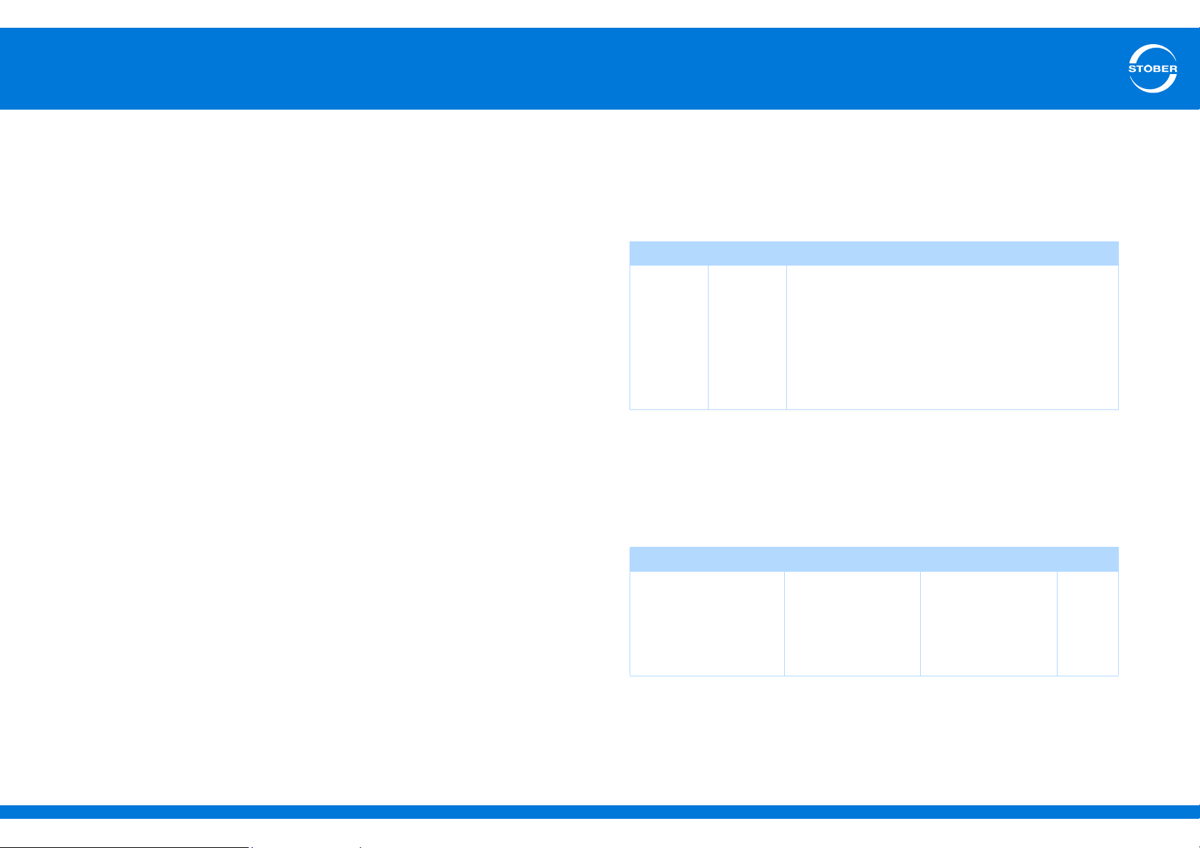
Device/software Documentation Contents ID
SD6 drive controllers Manual Technical data,
442426
installation,
connection, setup,
commissioning and
customer service
Page 5
1
General Information
Commissioning Instructions SD6
1.3 Further support
If you have technical questions that are not answered by this document,
please contact:
• Phone: +49 7231 582-3060
• E-mail: [email protected]
1.4 Abbreviations, symbols, indexes
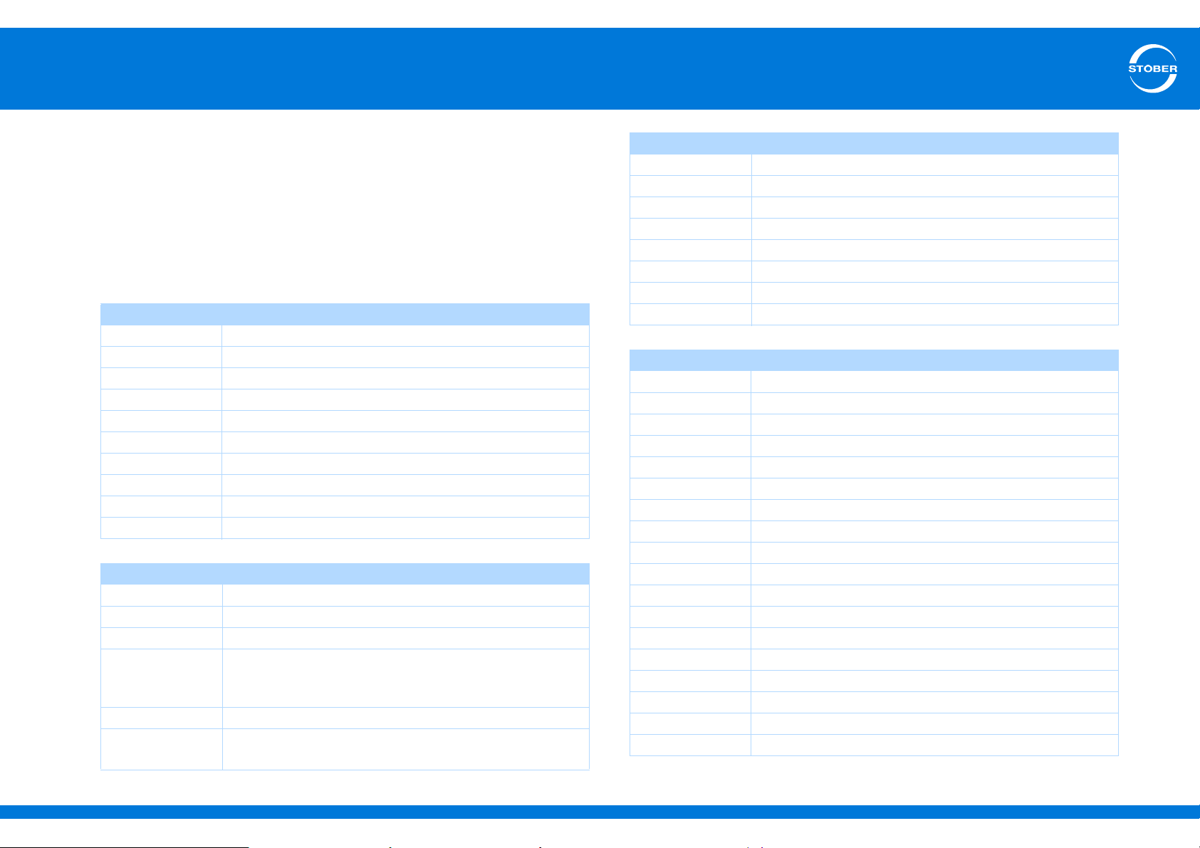
Abbreviations
AES Absolute Encoder Support
BG Size
CAN Controller Area Network
CiA Can in Automation
CNC Computerized Numerical Control
DC Direct Current
EMC Electromagnetic Compatibility
RCD Residual Current protective Device
UL Underwriters Laboratories
ZK DC link
Formula symbol
CCapacity
D Derating
f Frequency
K Ratio of the DC link circuit capacity being charged in the
compound DC link system to the max. charging capacity
of the drive controllers that are supplied with power
I Current
λ (lambda) Power factor; equivalent to cos φ between the effective
and apparent power
Formula symbol
n Speed
p Number of pole pairs
P (Effective) power
R Resistance
T Temperature
τ (tau) Thermal time constant
tTime
UVoltage
Indices
1 Input
2 Output
amb Ambient
BBrake
BAT Battery
BR Braking resistor
CH Brake chopper
Supply Supply current
hHeight
max Maximum
min Minimum
N Nominal
Mains Mains power supply
off Off
on On
PWM Pulse Width Modulation
T Temperature
VLoss
ID 442537.01 5WE KEEP THINGS MOVING
Page 6
1
General Information
Commissioning Instructions SD6
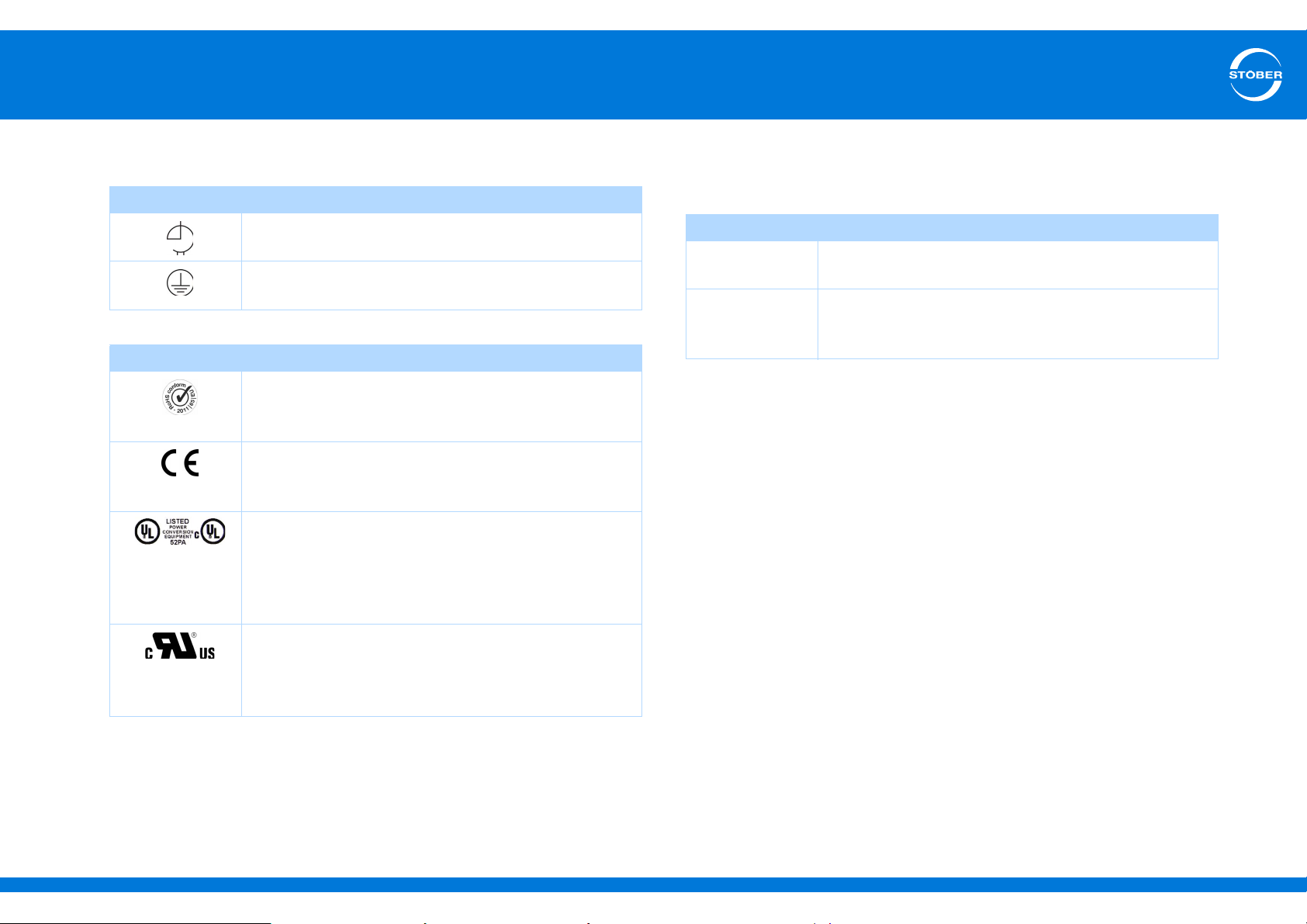
1.5 Symbols, identifiers, marks
Symbols
EN 61558-2-20
Choke without overload protection.
Grounding symbol according to IEC 60417-5019
(DB:2002-10).
Identification and test symbols
Lead-free identifier for RoHS
Lead-free identifier according to RoHS directive 2011-65-
EU.
CE mark
Manufacturer's self declaration: The product meets the
requirements of EU directives.
UL test mark
This product is listed by UL for the USA and Canada.
Representative samples of this product have been
evaluated by UL and meet the requirements of applicable
standards.
UL test marks for recognized component
This component or material is recognized by UL.
Representative samples of this product have been
evaluated by UL and meet applicable requirements.
The following names that are used in conjunction with the device, its
optional equipment and its accessories are trademarks or registered
trademarks of other companies:
Trademarks
CANopen,
CiA
EtherCAT EtherCAT and the EtherCAT logo are registered
CANopen and CiA are registered Community trademarks
of CAN in Automation e.V., Nuremberg, Germany.
trademarks of Beckhoff Automation GmbH, Verl,
Germany.
All other trademarks that are not listed here are the property of their
respective owners.
ID 442537.01 6WE KEEP THINGS MOVING
Page 7
2
Notes on safety
Commissioning Instructions SD6
2 Notes on safety
The devices can represent a source of danger. Therefore observe
• the safety guidelines, technical rules and regulations given in the
following sections
• and points.
STOBER shall assume no liability for damage resulting from failure to
comply with the instruction manual or relevant regulations. We reserve
the right to make technical changes for the purpose of improving the
devices.
2.1 Operation in accordance with its intended
use
As defined by DIN EN 50178 (previously VDE 0160), the drive
controllers are electrical equipment operating as power electronics to
control the flow of energy in high voltage systems. They are designed
exclusively for installation in switching cabinets, protection class at least
IP54, and for supplying
• synchronous servo motors and
• asynchronous motors.
Designated use does not include connecting other electrical loads!
2.2 Component part of the product
The technical documentation is a component part of a product.
• Since the technical documentation contains important information,
always keep it handy in the vicinity of the device until the machine is
disposed of.
• If the product is sold, disposed of, or rented out, always include the
technical documentation with the product.
2.3 Risk assessment
Before the manufacturer may bring a machine onto the market, he must
conduct a risk assessment according to Machine Directive 06/42/EC.
As a result, the risks associated with the use of the machine are
determined. The risk assessment is a multi-stage and iterative process.
On no account can sufficient insight into the Machine Directive be given
as part of this documentation. For this reason, seek detailed information
about the norms and legal position. When installing the drive controller
in machines, commissioning is forbidden until it has been determined
that the machine meets the requirements of EC Directive 06/42/EC.
2.4 Qualified personnel
Devices may cause residual risks. For this reason, all work on the
devices as well as operation and disposal must only be performed by
qualified personnel who are aware of the possible dangers.
Qualified personnel are persons who have acquired the authorisation to
perform these activities by
• Training from specialists and/or
• Instruction from specialists
In addition, they must have
• read,
• understood and
• observed the applicable regulations, legal provisions, rules and
standards and existing technical documentation including the safety
information contained in it.
ID 442537.01 7WE KEEP THINGS MOVING
Page 8
2
Notes on safety
Commissioning Instructions SD6
2.5 Working on the machine
Apply the 5 safety rules in the order stated before performing any work
on the machine:
1. Disconnect.
Also ensure that the auxiliary circuits are disconnected.
2. Protect against being turned on again.
3. Check that voltage is not present.
4. Ground and short circuit.
5. Cover or block off adjacent live parts.
Information
Note that the discharge time of the DC link capacitors is up to 5
minutes. You can only determine the absence of voltage after this
time period.
2.6 Disposal
Please comply with the latest national and regional regulations! Dispose
of the individual parts separately depending on their nature and
currently valid regulations such as, for example:
• Electronic scrap (PCBs)
•Plastic
• Sheet metal
• Copper
• Aluminum
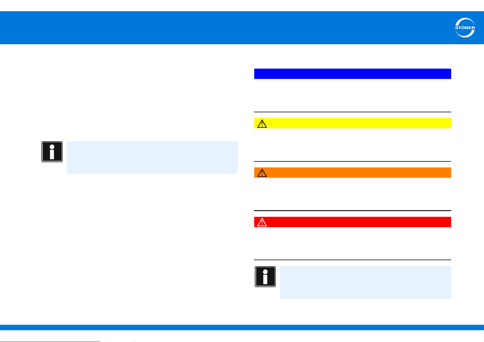
2.7 Presentation of notes on safety
NOTICE
Notice
means that property damage may occur
if the stated precautionary measures are not taken.
CAUTION!
Caution
with warning triangle means that minor injury may occur
if the stated precautionary measures are not taken.
WARNING!
Warning
means that there may be a serious danger of death
if the stated precautionary measures are not taken.
DANGER!
Danger
means that serious danger of death exists
if the stated precautionary measures are not taken.
Information
refers to important information about the product or serves to
emphasize a section in the documentation to which the reader
should pay special attention.
ID 442537.01 8WE KEEP THINGS MOVING
Page 9
3
Technical data
Commissioning Instructions SD6
3 Technical data
3.1 Notes on safety
Drive controllers are products subject to sales restrictions in accordance
with IEC 61800-3.
The drive controllers are not designed for use in a public low frequency
network that supplies residential areas.
In a residential environment this product may cause high-frequency
interference. If this occurs the user may be asked to take suitable
measures.
The drive controllers are not designed for use in a public low frequency
network that supplies residential areas. High-frequency interference
can be expected if the drive controllers are used in a network of this
type.
Always operate the devices within the limits specified in the technical
data.
The following applications are prohibited:
• Use in areas subject to explosion hazard
• Use in environments with harmful substances as specified by EN
60721, for example oils, acids, gases, vapors, dust and radiation
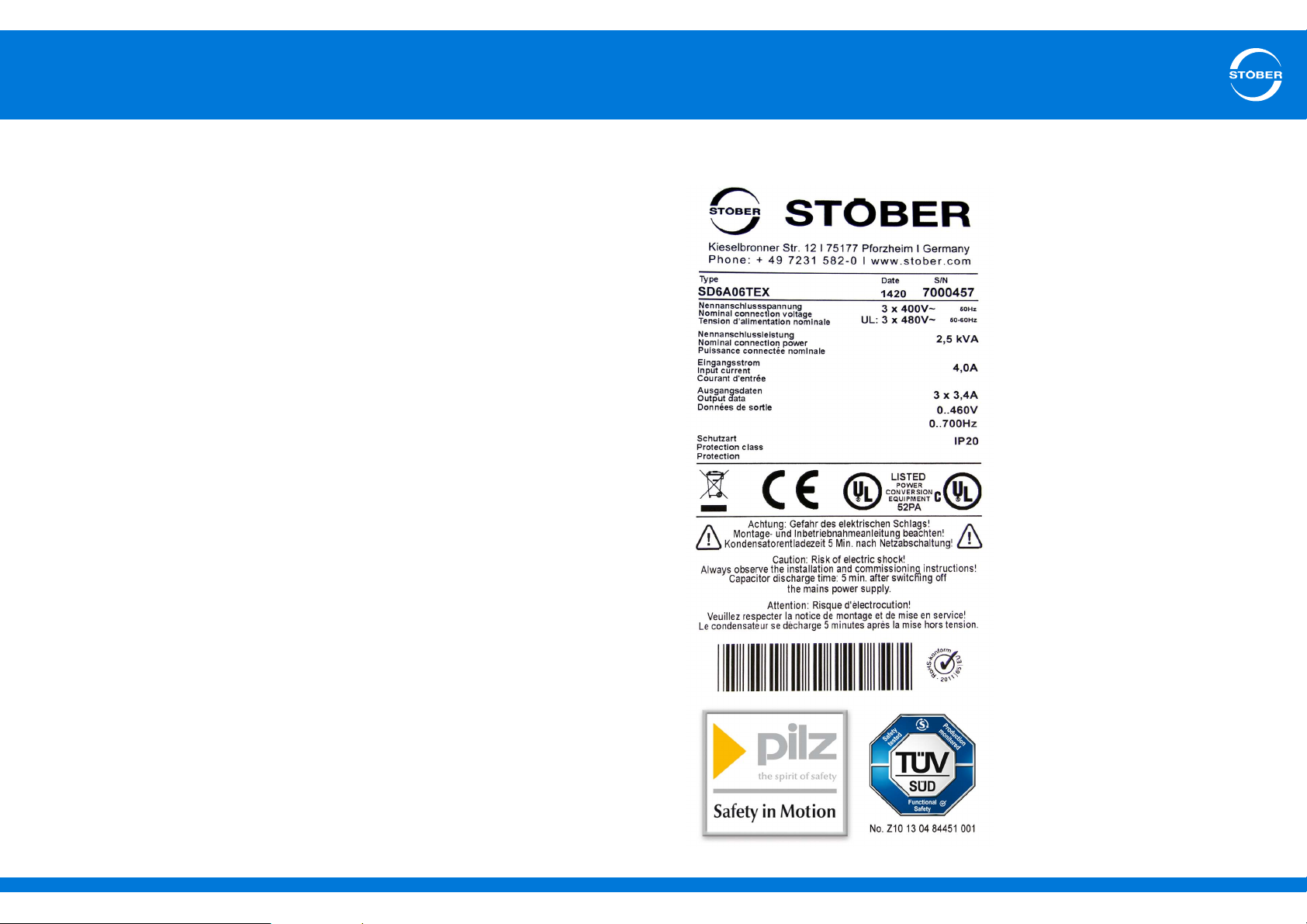
3.2 Nameplate
Implementation of the following applications is only permitted after
approval is obtained from STOBER:
• Use in non-stationary applications
ID 442537.01 9WE KEEP THINGS MOVING
Page 10
3
Technical data
Commissioning Instructions SD6
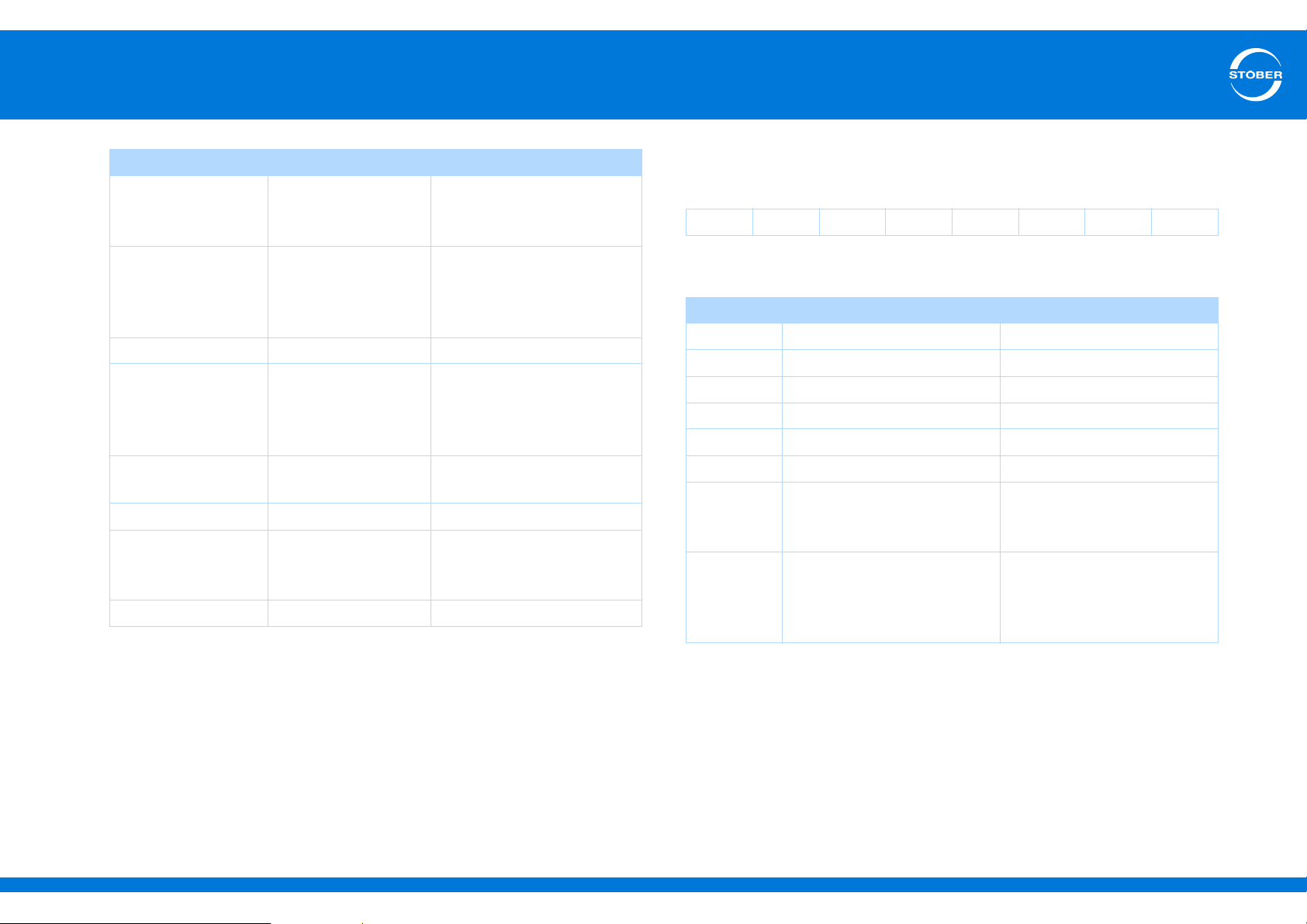
Designation Value in the example Meaning
Type SD6A06TEX Drive controller type
according to the type
designation
Date 1318 Production week in format
YYWW, in the example
shown here year 2013, week
18
S/N 7000204 Serial number
Nominal connection
voltage
Nominal connection
power
Input current 4.0 A Input current
Output data 3 x 3.4 A
Protection class IP20 Protection class
3 x 400 V ~
50 Hz
UL: 3 x 480 V ~ 50–
60 Hz
2.5 kVA Nominal connection power
0...460 V
0...700 Hz
Nominal connection voltage
Output data
3.3 Type designation
Sample code
SD 6 A 0 6 T E X
Explanation
Code Designation Design
SD Type Servo Drive
6 Generation 6th generation
A, B Version
0 – 3 Size
0 – 9 Power output stage (Within the size)
T Safety module ST6: Safe Torque Off (STO)
N
E
C
N
X
R
I
Communication module Empty
EC6: EtherCAT
CA6: CANopen
Terminal module Empty
XI6: Extended I/O
RI6: Resolver I/O
IO6: Standard I/O
UL test mark
UL and cUL (CSA-UL) certified drive controllers with corresponding test
mark meet the requirements of standards UL 508C and UL 840.
ID 442537.01 10WE KEEP THINGS MOVING
Page 11
3
Technical data
Commissioning Instructions SD6
3.4 Sizes
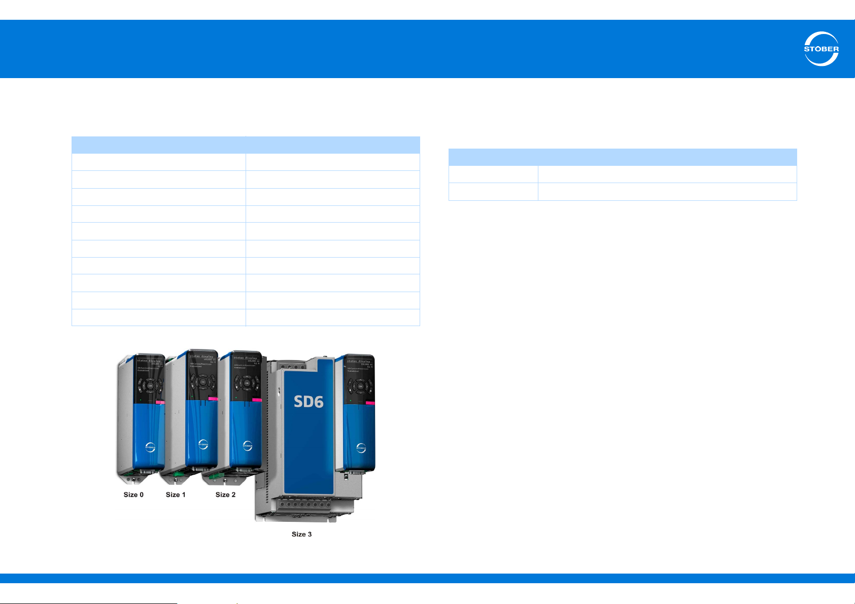
The drive controller SD6 includes the following types and sizes:
Type Size
SD6A02 0
SD6A04 0
SD6A06 0
SD6A14 1
SD6A16 1
SD6A24 2
SD6A26 2
SD6A34 3
SD6A36 3
SD6A38 3
3.5 Electrical Data
3.5.1 Control board
Control board
U
20.4 – 28.8 V
1
a)
I
1max
a) Depending on the accessories used.
1.5 A
ID 442537.01 11WE KEEP THINGS MOVING
Page 12
3
Technical data
Commissioning Instructions SD6
3.5.2 Power board
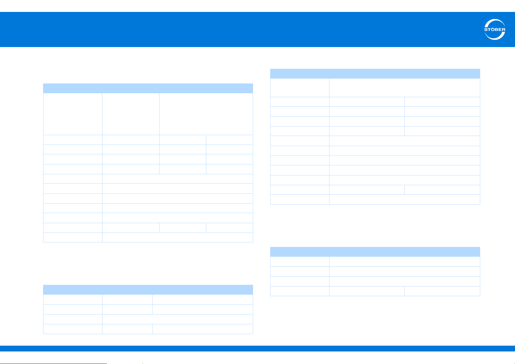
3.5.2.1 Size 0: SD6A0x
Type SD6A02 SD6A04 SD6A06
U
1
(L1 – N) 1 x 230 V,
+20 % / -40 %,
50/60 Hz;
(L1 – N) 1 x 240 V,
50/60 Hz
I
(f
1N
I
1N
I
2N
I
2N
I
2max
I
2max
f
PWM
f
2
U
2
= 4 kHz) 8.3 A 2.8 A 5.4 A
PWM
(f
= 8 kHz) 6 A 2.2 A 4 A
(f
(f
PWM
= 4 kHz)
PWM
= 8 kHz)
PWM
(f
= 4 kHz) 180 % for 5 s; 150 % for 30 s
PWM
(f
= 8 kHz) 250 % for 2 s; 200 % for 5 s
PWM
a)
b)
4 A 2.3 A 4.5 A
3 A 1.7 A 3.4 A
Adjustable: 4, 8, 16 kHz
PV (I2 = IN) 80 W 65 W 90 W
P
(I2 = 0 A) Max. 30 W
V
a) Note the derating for 4 kHz.
b) Note the derating for 8 kHz.
c) Note the details for the nominal output current and derating for 16 kHz.
d) Depending on the option modules and encoders connected.
Properties of the brake chopper
Type SD6A02 SD6A04 SD6A06
U
400 – 420 V 780 – 800 V
CHon
U
CHoff
R
BRmin
P
BRmax
360 – 380 V 740 – 760 V
1.8 kW 6.4 kW
(L1 – L3) 3 x 400 V,
+32 % / -50 %,
50/60 Hz;
(L1 – L3) 3 x 480 V,
50/60 Hz
0 – 700 Hz
0 – U
1
d)
100 Ω
c)
3.5.2.2 Size 1: SD6A1x
Type SD6A14 SD6A16
U
1
I
(f
1N
I
1N
I
2N
I
2N
I
2max
I
2max
f
PWM
f
2
U
2
= 4 kHz) 12 A 19.2 A
PWM
(f
= 8 kHz) 9.3 A 15.8 A
(f
(f
PWM
= 4 kHz)
PWM
= 8 kHz)
PWM
(f
= 4 kHz) 180 % for 2 s; 150 % for 30 s
PWM
(f
= 8 kHz) 250 % for 2 s; 200 % for 5 s
PWM
a)
b)
PV (I2 = IN) 170 W 200 W
P
(I2 = 0 A) Max. 30 W
V
a) Note the derating for 4 kHz.
b) Note the derating for 8 kHz.
c) Note the details for the nominal output current and derating for 16 kHz.
d) Depending on the option modules and encoders connected.
Properties of the brake chopper
Type SD6A14 SD6A16
U
780 – 800 V
CHon
U
CHoff
R
BRmin
P
BRmax
(L1 – L3) 3 400 V, +32 % / -50 %, 50/60 Hz;
(L1 – L3) 3 480 V, 50/60 Hz
10 A 16 A
6 A 10 A
Adjustable: 4, 8, 16 kHz
c)
0 – 700 Hz
0 – U
1
d)
740 – 760 V
47 Ω
6.4 kW 13.6 kW
ID 442537.01 12WE KEEP THINGS MOVING
Page 13
3
Technical data
Commissioning Instructions SD6
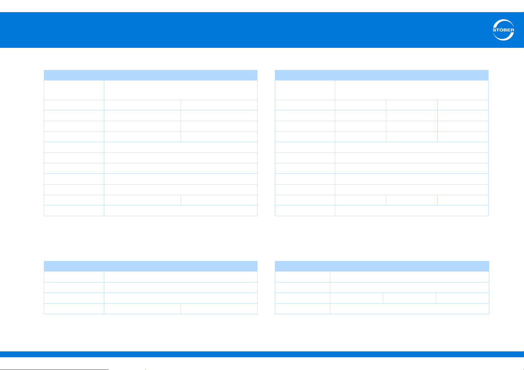
3.5.2.3 Size 2: SD6A2x
Type SD6A24 SD6A26
U
1
I
(f
1N
I
1N
I
2N
I
2N
I
2max
I
2max
f
PWM
f
2
U
2
= 4 kHz) 26.4 A 38.4 A
PWM
(f
= 8 kHz) 24.5 A 32.6 A
PWM
(f
(f
= 4 kHz)
PWM
= 8 kHz)
PWM
(f
= 4 kHz) 180 % for 5 s; 150 % for 30 s
PWM
(f
= 8 kHz) 250 % for 2 s; 200 % for 5 s
PWM
a)
b)
PV (I2 = IN) 220 W 280 W
P
(I2 = 0 A) Max. 30 W
V
a) Note the derating for 4 kHz.
b) Note the derating for 8 kHz.
c) Note the details for the nominal output current and derating for 16 kHz.
d) Depending on the option modules and encoders connected.
(L1 – L3) 3 400 V, +32 % / -50 %, 50/60 Hz;
(L1 – L3) 3 480 V, 50/60 Hz
22 A 32 A
14 A 20 A
Adjustable: 4, 8, 16 kHz
c)
0 – 700 Hz
0 – U
1
d)
3.5.2.4 Size 3: SD6A3x
Type SD6A34 SD6A36 SD6A38
U
1
I
(f
1N
I
1N
I
2N
I
2N
I
2max
I
2max
f
PWM
f
2
U
2
= 4 kHz) 45.3 A 76 A 76 A
PWM
(f
= 8 kHz) 37 A 62 A 76 A
PWM
(f
(f
= 4 kHz)
PWM
= 8 kHz)
PWM
(f
= 4 kHz) 180 % for 5 s; 150 % for 30 s
PWM
(f
= 8 kHz) 250 % for 2 s; 200 % for 5 s
PWM
a)
b)
PV (I2 = IN) 350 W 600 W 1000 W
P
(I2 = 0 A) Max. 55 W
V
a) Note the derating for 4 kHz.
b) Note the derating for 8 kHz.
c) Note the details for the nominal output current and derating for 16 kHz.
d) Depending on the option modules and encoders connected.
(L1 – L3) 3 x 400 V, +32 % / -50 %, 50/60 Hz;
(L1 – L3) 3 x 480 V, 50/60 Hz
44 A 70 A 85 A
30 A 50 A 60 A
Adjustable: 4, 8, 16 kHz
c)
0 – 700 Hz
0 – U
1
d)
Properties of the brake chopper
Type SD6A24 SD6A26
U
780 – 800 V
CHon
U
CHoff
R
BRmin
P
BRmax
ID 442537.01 13WE KEEP THINGS MOVING
29.1 kW 29.1 kW
740 – 760 V
22 Ω
Properties of the brake chopper
Type SD6A34 SD6A36 SD6A38
U
CHon
U
CHoff
R
BRmin
P
BRmax
780 – 800 V
740 – 760 V
15 Ω
42 kW
Page 14
3
Technical data
Commissioning Instructions SD6
3.5.2.5 Derating
When dimensioning the drive controller, observe the derating of the
output current depending on the clock frequency, surrounding
temperature, and installation altitude. There is no restriction for a
surrounding temperature from 0° C to 45° C and an installation altitude
of 0 m to 1000 m. The details given below apply to values outside these
ranges.
3.5.2.5.1 Effect of the clock frequency
Changing the clock frequency f
produced by the drive. However, increasing the clock frequency results
in increased losses. During project configuration, define the highest
clock frequency and use it to determine the nominal output current I
for dimensioning the drive controller.
Type Nominal output current I2N [A]
4 kHz 8 kHz 16 kHz
SD6A02 4 3 2
SD6A04 2.3 1.7 1.1
SD6A06 4.5 3.4 2.3
SD6A14 10 6 4
SD6A16 16 10 5.7
SD6A24 22 14 8.1
SD6A26 32 20 12
SD6A34 44 30 18
SD6A36 70 50 31
SD6A38 85 60 37.8
affects the amount of noise
PWM
2N
3.5.2.5.2 Effect of surrounding temperature
Derating depending on the ambient temperature is determined as
follows:
• 0° C to 45° C: No restrictions (D
= 100 %)
T
• 45° C to 55° C: Derating -2.5 % / K
Example
The drive controller will be operated at 50° C.
The resulting derating factor D
for DT = 100 % - 5 2.5 % = 87.5 %.
T
3.5.2.5.3 Effect of installation altitude
Derating depending on the installation altitude is determined as follows:
• 0 m to 1000 m above sea level: No restrictions (D
• 1000 m to 2000 m above sea level: Derating -1.5 % / 100 m
= 100 %)
h
Example
The drive controller will be installed at an altitude of 1500 m above sea
level.
The resulting derating factor D
for Dh = 100 % - 5 1.5 % = 92.5 %.
h
3.5.2.5.4 Calculating the derating
Follow these steps for the calculation:
1. Determine the highest clock frequency (f
during operation and use it to determine the nominal current I
) that will be used
PWM
(see
N
section 3.5.2.5.1).
2. Determine the derating factors for installation altitude and
surrounding temperature (see section 3.5.2.5.3 and 3.5.2.5.2).
3. Calculate the output current I
I
= I2N DT D
2
h
according to the following formula:
2
Information
Enter the defined clock frequency for setting up the drive controller
in B24.
ID 442537.01 14WE KEEP THINGS MOVING
Page 15

3
Technical data
Commissioning Instructions SD6
Example
A drive controller of type SD6A06 will be operated at a clock frequency
of 8 kHz at an altitude of 1500 m above sea level and an surrounding
temperature of 50° C.
The nominal current of the SD6A06 at 8 kHz is 3.4 A (see 3.5.2.5.1).
The resulting derating factor D
(see 3.5.2.5.3).
The resulting derating factor D
(see 3.5.2.5.2).
The output current to be observed for project configuration is:
I
= 3.4 A 0.875 0.925 = 2.75 A
2
for DT = 100 % - 5 2.5 % = 87.5 %
T
for Dh = 100 % - 5 1.5 % = 92.5 %
h
3.6 Mechanical Data
3.6.1 Device features
Protection class of the
device
Protection class of the
control cabinet
Radio interference
suppression
Overvoltage category III to EN 61800-5-1
Size Weight
Without packaging [kg] With packaging [kg]
0 2,53 3.52
1 3.7 5.47
2 5.05 6.49
3 13.3 14.8
IP 20
At least IP 54
EN 61800-3, interference emission class C3
If you order a drive controller with accessory parts, the weight is
increased as follows:
• Communication module: 50 g
• Terminal module: 135 g
ID 442537.01 15WE KEEP THINGS MOVING
Page 16
3
d2
d1
h2
h1
h3
e
f
a
b
w
Technical data
Commissioning Instructions SD6
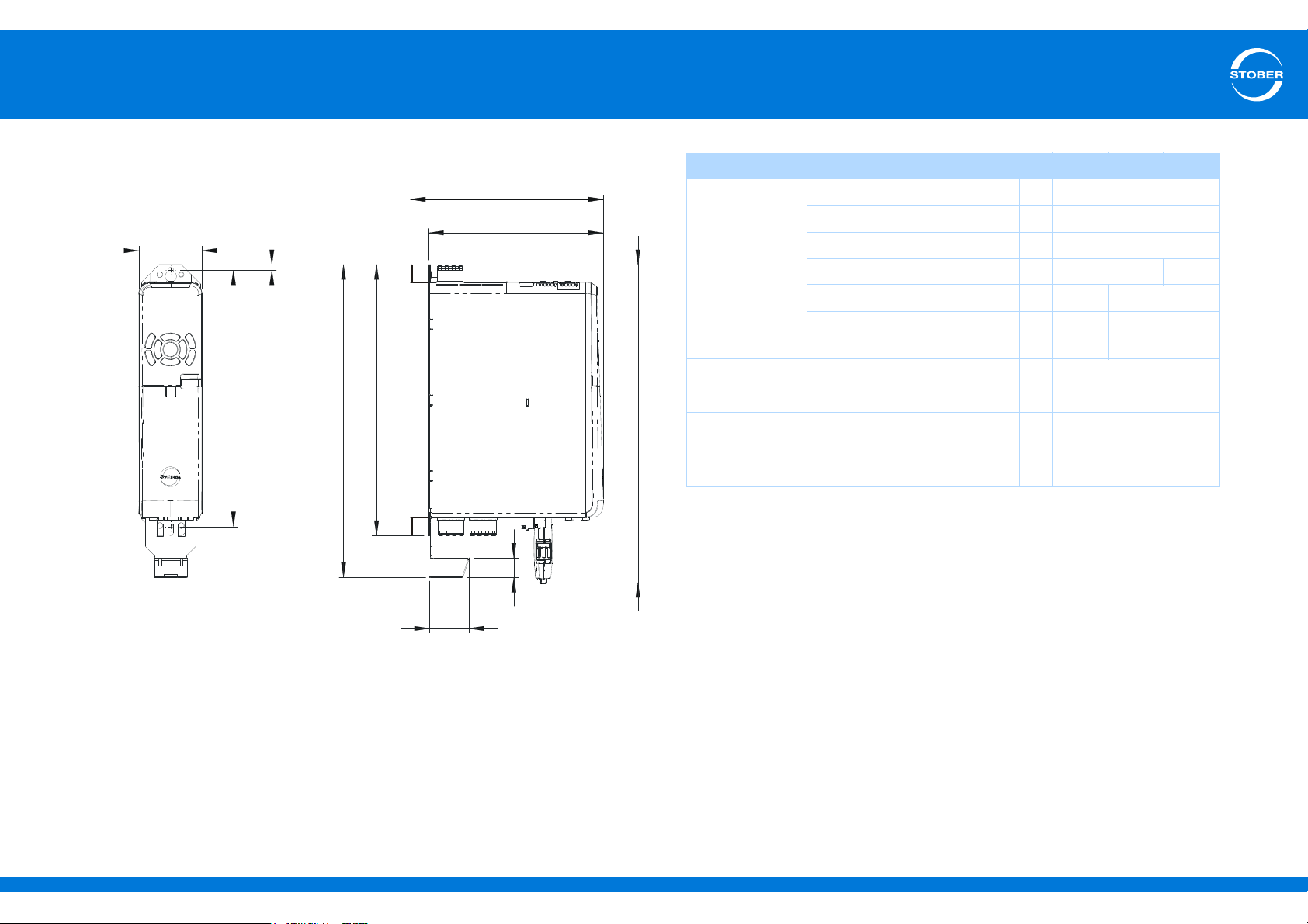
3.6.2 Dimensions
Dimensions [mm] Size 0 Size 1 Size 2
Drive controller Height h
Height incl. EMC shroud h
Height incl. AES h
Width w 70 105
Depth d
Depth incl. braking resistor
RB 5000
EMC shroud Height e 27
Depth f 40
Fastening holes Vertical distance a 283+2
Vertical distance
to upper edge
1
2
3
194 284
1
d
212 302
2
b6
300
355
367
ID 442537.01 16WE KEEP THINGS MOVING
Page 17
3
Technical data
Commissioning Instructions SD6
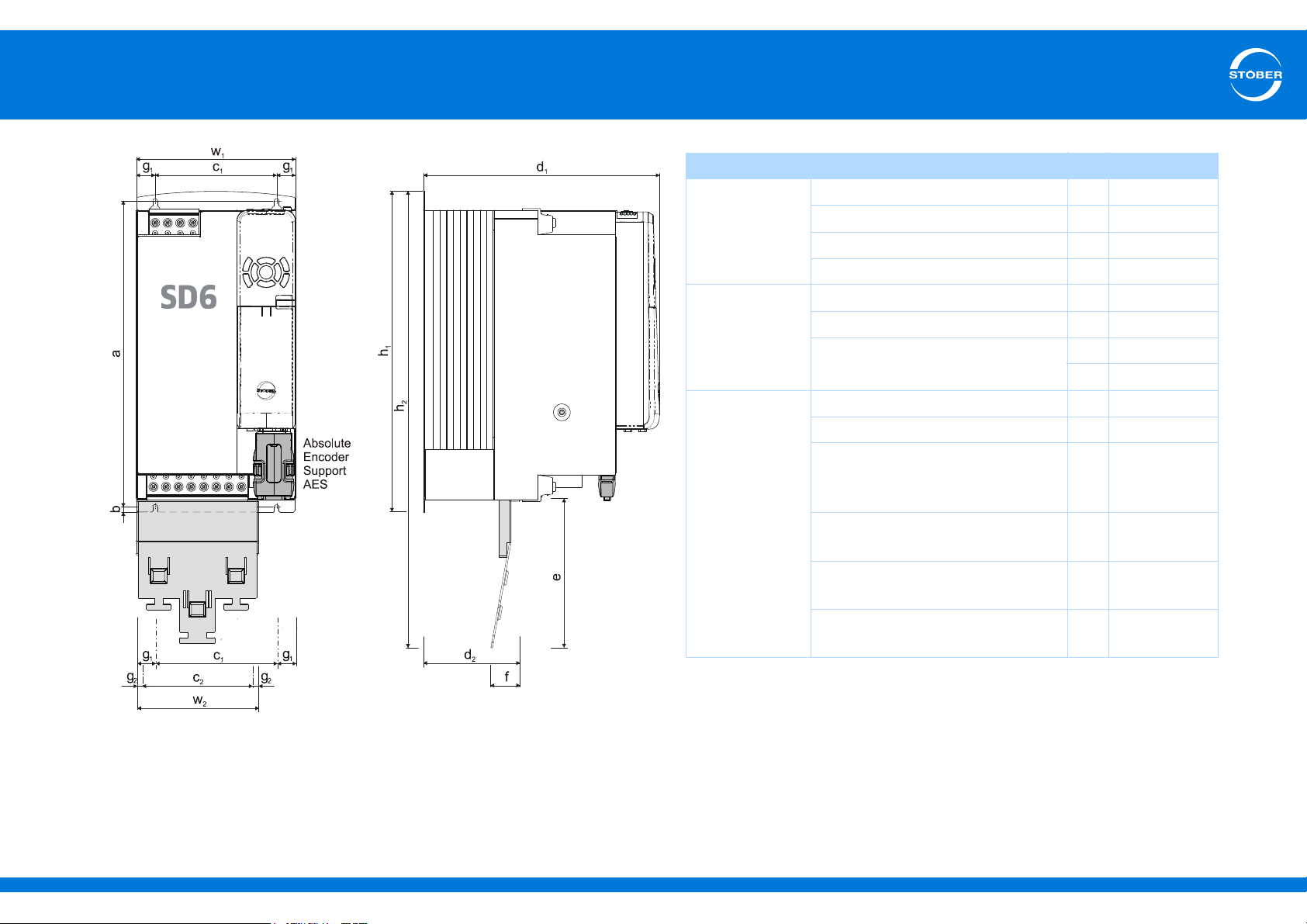
Dimensions [mm] Size 3
Drive controller Height h
Height incl. EMC shroud h
Width w
Depth d
1
2
1
1
382.5
540
190
305
EMC shroud Height e 174
Width w
2
147
Depth f 34
Fastening
holes
d
2
113
Vertical distance a 365+2
Vertical distance from bottom edge b 6
Horizontal distance from the
fastening holes of the drive
c
1
150+0.2/-0.2
controller
Horizontal distance from the side
edge of the drive controller
Horizontal distance from the
g
1
c
2
20
132
fastening holes of the EMC shroud
Horizontal distance from the side
g
2
7.5
edge of the EMC shroud
ID 442537.01 17WE KEEP THINGS MOVING
Page 18
4
Installation
Commissioning Instructions SD6
4Installation
4.1 Notes on safety
Installation work is only admissible when no voltage is present. Observe
the 5 safety rules (see chapter 2.5 Working on the machine).
Remove the additional covers before commissioning so that the device
will not overheat.
Note the minimum open areas specified in the technical data during
installation to prevent the drive controller from overheating.
Protect the device against falling parts (bits or strands of wire, pieces of
metal, etc.) during installation or other work in the control cabinet. Parts
with conductive properties may result in a short circuit or device failure
within the drive controller.
4.2 Drive controller
WARNING!
Electrical voltage!
Danger to life caused by touching live parts!
Activate the control cabinet according to the 5 safety rules.
Requirements:
• Prevent condensation, for example with anti-condensation heating
elements.
• Note that drive controllers in storage must be used annually or no
later than before commissioning.
• For reasons related to EMC, use mounting plates with a conductive
surface (unpainted, etc.).
• Fasten the devices onto the mounting plate with M5 screws.
• Attach the devices vertically.
• Avoid installation above or in the immediate vicinity of heatgenerating devices
such as output deraters or braking resistors.
• To ensure there is sufficient air circulation in the control cabinet,
observe the minimum clearances.
• A contact plan of the system in which the connection of the drive
controller is described must be present.
You need:
• a tool to drill the tapped holes in the mounting plate.
• a tool to tighten the fastening screws.
Drive controller installation
1. If present, install both a terminal module and a communication
module (see section
modules
2. Prepare the mounting plate according to the separately enclosed
drilling diagram.
3. Install the drive controller on the mounting plate. Make certain chips
and oil are cleaned from the mounting plate.
4. Connect the housing ground (see section
5. Connect the drive controller, terminal module and communication
module according to the contact plan.
).
4.3 Terminal modules and 4.4 Communication
5.4.3 Housing ground).
ID 442537.01 18WE KEEP THINGS MOVING
Page 19
4
Installation
Commissioning Instructions SD6
4.3 Terminal modules
WARNING!
Danger of personal injury and material damage due to electric
shock!
Always switch off all power supply voltage before working on the
drive controller! Note that the discharge time of the DC link
capacitors is 5 minutes. You can only determine the absence of
voltage after this time period.
CAUTION!
Danger of property damage due to electrostatic discharge, among
others!
Provide suitable protective measures while handling open PCBs
(e.g., ESD clothing, environment free of dirt and grease).
Do not touch the contact surfaces.
Analog and binary signals can only be connected via one of terminal
modules XI6, RI6 or IO6. Installation is identical for all terminal modules.
You need:
• A Torx screwdriver TX10.
• The accessory enclosed with the terminal module.
Terminal module installation
1. Press the spring lock on the front cover lightly to unlock it.
2. Push the front cover down as far as it will go.
3. Remove the cover towards the front.
4. Insert the terminal module so that the recesses on the module and
the holding down mechanisms on the drive controller can be guided
past one another. The rear of the plug-in card must be resting
against the drive controller.
5. Push the terminal module up so that the pin contacts are pushed
into the female connector strip.
6. Fasten the terminal module onto the drive controller with the
fastening screw.
ID 442537.01 19WE KEEP THINGS MOVING
Page 20
4
Installation
Commissioning Instructions SD6
4.4 Communication modules
WARNING!
Danger of personal injury and material damage due to electric
shock!
Always switch off all power supply voltage before working on the
drive controller! Note that the discharge time of the DC link
capacitors is 5 minutes. You can only determine the absence of
voltage after this time period.
CAUTION!
Danger of property damage due to electrostatic discharge, among
others!
Provide suitable protective measures while handling open PCBs
(e.g., ESD clothing, environment free of dirt and grease).
Do not touch the contact surfaces.
You need:
• A Torx screwdriver TX10.
• The cover and screw included with the communication module.
Installation of the communication module
1. Loosen the fastening screw for the dummy cover on the top of the
drive controller.
2. Push the communication module into the drive controller on the
guide rails.
3. Push the module in so that the pin contacts are pushed into the
female connector strip.
4. Insert the tips of the cover included with the communication module
into the recess in the front at an angle.
5. Set the cover down on the drive controller so that the tips are
resting under the edge.
6. Fasten the cover with the two screws.
You will need the EC6 or CA6 communication module to connect
EtherCAT or CANopen. EC6 is installed on the upper slot, the same as
CA6. The installation is identical for both communication modules.
ID 442537.01 20WE KEEP THINGS MOVING
Page 21
4
Installation
Commissioning Instructions SD6
4.5 Quick DC-Link
WARNING!
Danger of personal injury and material damage due to electric
shock!
Always switch off all power supply voltage before working on the
drive controller! Note that the discharge time of the DC link
capacitors is 5 minutes. You can only determine the absence of
voltage after this time period.
Quick DC-Link – installation of DL6 modules
Requirements:
• For reasons related to EMC, use mounting plates with a conductive
surface (unpainted, etc.).
• You have tapped holes for threaded bolts on the mounting plate at
the installation location, taking into consideration the different device
dimensions.
• Avoid installation above or in the immediate vicinity of heatgenerating devices
such as output deraters or braking resistors.
• To ensure there is sufficient air circulation in the control cabinet,
observe the minimum clearances.
• The copper rails must be straight, smooth, free of burrs and cleaned.
You need:
• Copper rails (cross-sectional dimension: 5 x 12 mm).
• The threaded bolts enclosed with the DL6 modules as well as the
corresponding screws and washers.
• The insulation inserts and holding clamps enclosed with the DL6
modules.
• A PH2 Phillips screwdriver.
• An 8 mm hexagonal socket wrench.
Installation of DL6 modules
1. Fasten the DL6 modules onto the mounting plate with the threaded
bolts.
2. Insert the insulation inserts between the modules and on both ends.
3. Clean the copper rails, especially on the contact points.
4. Insert the two copper rails one after the other and fasten them in
place with two holding clamps per module. Make certain the contact
points of the copper rails do not become contaminated.
5. Pull the X30 clamps off the relevant drive controllers.
6. Connect the brown cables D+ to X30 terminals D+ and the black
cables D- to X30 terminals D-.
7. Size 3:
Mount the EM6A3 EMC shrouds as described in section
shroud
8. Place the drive controllers on the respective guides.
9. Press the drive controllers down on the respective guides.
10. Sizes 0 – 2:
Mount the EM6A0 EMC shrouds as described in section
shroud
11. Attach each drive controller to the corresponding threaded bolt with
the enclosed screws and washers.
12. Fasten the X30 terminals to the bottoms of the corresponding drive
controllers.
.
.
4.7 EMC
4.7 EMC
ID 442537.01 21WE KEEP THINGS MOVING
Page 22
4
Installation
Commissioning Instructions SD6
4.6 Bottom brake resistor
WARNING!
Danger of personal injury and material damage due to electric
shock!
Always switch off all power supply voltage before working on the
drive controller! Note that the discharge time of the DC link
capacitors is 5 minutes. You can only determine the absence of
voltage after this time period.
Requirements:
• You have tapped holes for threaded bolts on the mounting plate in
the control cabinet at the installation location, taking into
consideration the different device dimensions. The threaded bolts
are included with the submounting braking resistor.
You need:
• The threaded bolts included with the submounting brake resistor.
• The screws and washers included with the submounting brake
resistor.
• A PH2 Phillips screwdriver.
• An 8 mm hexagonal socket wrench.
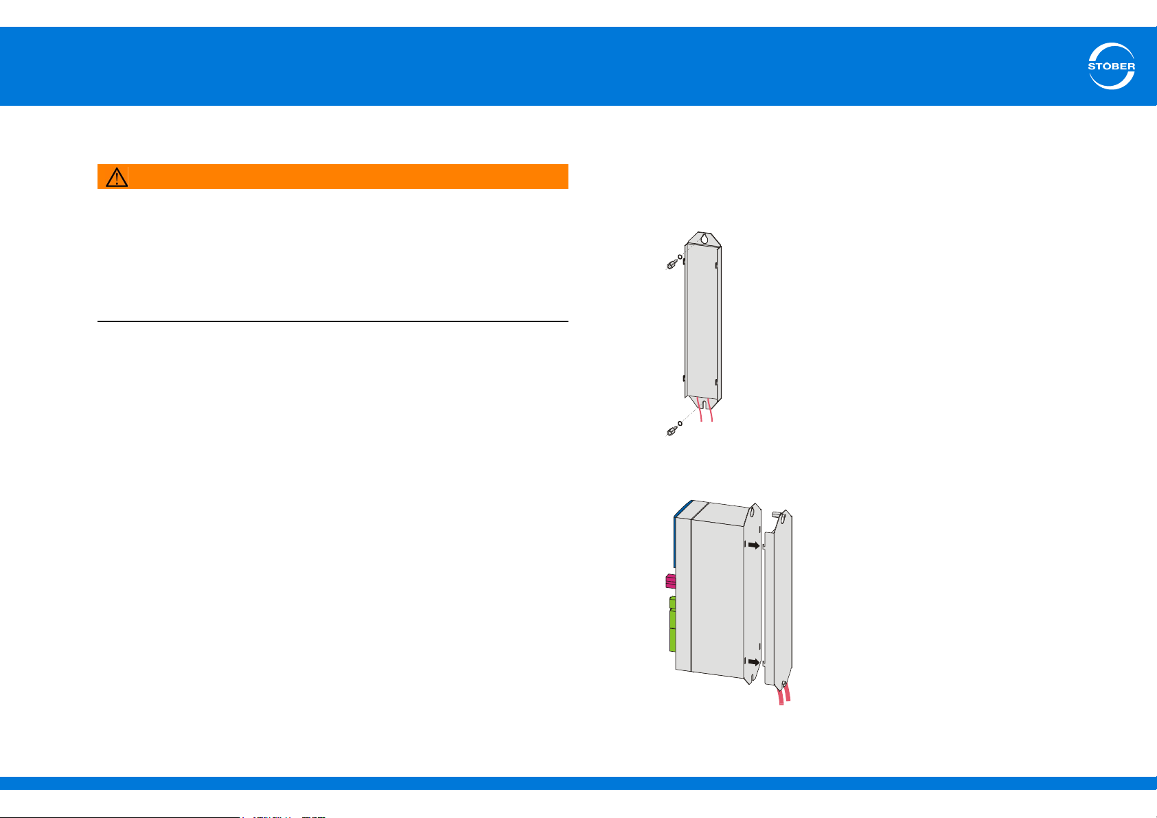
Installation of the submounting brake resistor
1. Attach the bottom brake resistor to the mounting plate with the
studs:
2. Place the device on the guides:
ID 442537.01 22WE KEEP THINGS MOVING
Page 23
4
Installation
Commissioning Instructions SD6
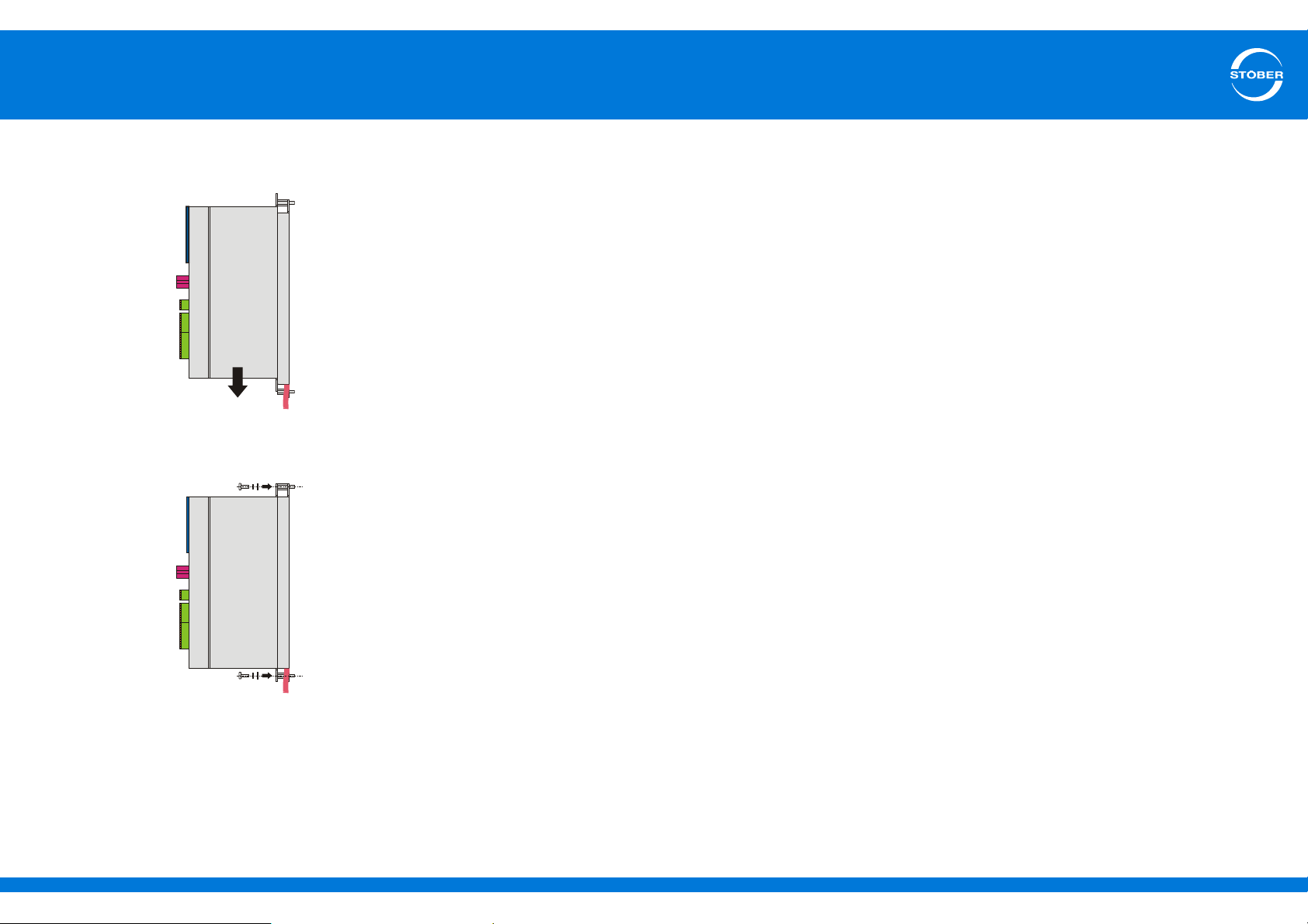
3. Press the device down on the guides:
4. Attach the device to the studs with the screws and washers:
5. Connect the braking resistor.
Refer to the terminal description for X30 (R+ and R-) for proper
connection of the cable, see section
6. Parameterize the braking resistor in the drive controller.
5.5.11.
You have installed the submounting brake resistor.
ID 442537.01 23WE KEEP THINGS MOVING
Page 24
4
Installation
Commissioning Instructions SD6
4.7 EMC shroud
WARNING!
Danger of personal injury and material damage due to electric
shock!
Always switch off all power supply voltage before working on the
drive controller! Note that the discharge time of the DC link
capacitors is 5 minutes. You can only determine the absence of
voltage after this time period.
You can use the EM6 EMC shroud to connect the cable shield of the
power cable. Different designs are available for sizes 0 to 2 and also for
size 3. Attachment of this accessory part accordingly differs on drive
controllers sizes 0 to 2 compared to attachment on drive controllers size
3.
Preconditions:
• Sizes 0 – 2: You have already installed the drive controller in the
control cabinet, if necessary in combination with a Quick DC-Link or
a bottom brake resistor.
Attaching the EMC shroud EM6A0 to a drive controller size 0, 1 or 2
1. Undo the lower fastening screw and washers of the drive controller.
2. Insert the shroud into the openings on the bottom of the drive
controller at a slight angle.
3. Press the back of the shroud either directly on the mounting plate
or on the stud in the bottom.
4. Attach the shroud to the drive controller and mounting plate or studs
with the fastening screw and washers.
Attaching the EMC shroud EM6A3 to a drive controller size 3
1. Fasten the shroud onto the bottom of the drive controller with the
enclosed fastening screws in the tapped holes provided for that
purpose (max. tightening torque: 2.4 Nm).
You need:
• A PH2 Phillips screwdriver.
• Size 3: The two enclosed screws and washers (combination screws
with toothed lock washer, M4x8).
ID 442537.01 24WE KEEP THINGS MOVING
Page 25
5
Connecting
Commissioning Instructions SD6
5 Connecting
5.1 Notes on safety
Connection work is only admissible when no voltage is present.
Observe the 5 safety rules (see chapter 2.5 Working on the machine).
Make note of the following points:
• The drive controller housing must be closed before you turn on the
power supply voltage.
• When the power supply voltage is turned on, hazardous voltages
may be present on the connection terminals and the cables
connected to them.
• The device is not reliably free of voltage simply because all the
displays are blank!
The following actions are prohibited while the power supply voltage is
turned on:
• Opening the housing
• Connecting or disconnecting connection clamps
• Connecting or disconnecting connection wiring
• Removing or installing accessories.
The protection class is protective grounding. Because of this, operation
is only admissible if the protective ground wire is connected according
to requirements.
The essential protective ground connections are identified by "PE" or
the international symbol for grounding (IEC 60417, symbol 5019 ).
Drive controllers are products subject to sales restrictions in accordance
with IEC 61800-3.
The drive controllers are not designed for use in a public low frequency
network that supplies residential areas.
In a residential environment this product may cause high-frequency
interference. If this occurs the user may be asked to take suitable
measures.
For information regarding use under UL conditions (UL – Underwriters
Laboratories) please pay close attention to section 2 in the SD6 manual
(see section 1.2 Other manuals).
Protect the device against falling parts (bits or strands of wire, pieces of
metal, etc.) during installation or other work in the control cabinet. Parts
with conductive properties may result in a short circuit or device failure
within the drive controller.
Use only copper conductors. For the corresponding lead cross-sections
consult standards DIN VDE 0298-4 or DIN EN 60204-1 (appendices D,
G) as well as the relevant terminal specifications in this documentation.
ID 442537.01 25WE KEEP THINGS MOVING
Page 26
5
Connecting
Commissioning Instructions SD6
5.2 General information
5.2.1 EMC connection
Information
This section provides general information on EMC-compliant
installation. This involves recommendations. Depending on the
application, ambient conditions as well as the legal requirements,
measures beyond these recommendations may be required.
• Lay the power line, motor cable and signal lines separately from
each other, e.g. in separate cable channels.
• Only use shielded, low-capacitance cables as motor cables.
• If the brake line is carried in the motor cable, it must be separately
shielded.
• Connect the shield of the motor cable with large contact areas and
in the immediate vicinity of the drive controller. Use the EM6 EMC
shroud to do this.
• Shield the cable for connection to a braking resistor if it exceeds a
length of 30 cm. In this case, connect the shield with large contact
areas and in the immediate vicinity of the drive controller.
• For motors with terminal boxes, connect the shield to the terminal
box with large contact areas. For example, use EMC cable screw
connections.
• Connect the shield of the control lines on one side with the reference
ground of the source, e.g. the PLC or CNC.
5.2.2 Selecting the cables
Note that the motor, cables and drive controller each have electrical
properties which influence one another. Unfavorable combinations
could possibly result in impermissible voltage peaks on the motor and
drive controller and therefore to increased wear.
Take into consideration the following instructions when selecting
suitable leads:
• Lead cross-sections for the cables to the motor:
Make certain you choose the permissible continuous open-circuit
current for the motor.
• Lead cross-sections for the power connection of the drive controller:
When choosing the mains fuse, make certain to select the maximum
admissible conductor cross-section of terminal X10. Be careful of
how the cables are laid and the surrounding temperature.
• Pay attention also to the trailability and torsional strength of the
leads.
• When using a motor brake, pay attention to the voltage drop in the
supply voltage on the lead.
ID 442537.01 26WE KEEP THINGS MOVING
Page 27
5
Connecting
Commissioning Instructions SD6
5.3 Wiring
Observe the regulations applicable for your machine or system when
installing the electrical equipment, e.g. DIN IEC 60364 or
DIN EN 50110.
5.4 Protective measures
The drive controllers are only suitable for operation on TN networks and
only for use in supply current networks that are able to provide a
maximally symmetrical nominal short circuit current at 480 volts
according to the following table.
Size Max. symmetrical nominal short-circuit current
Size 0 – size 2 5000 A
Size 3 10,000 A
5.4.1 Line fuse
The mains fuse ensures line and power protection in the drive controller.
You can use the following protective devices:
• Full range safety melt fuses for cable and circuit protection to IEC
60269-2-1/DIN VDE 0636, part 201 NH fuses (operating class gG in
accordance with IEC operating class specification or slow blow in
accordance with VDE)
• Circuit breaker with trigger characteristics C in accordance with
EN 60898
• Power circuit breaker
Type Input current
I
(8 kHz)
1N
SD6A02 5.9 A 8.3 A 10 A
SD6A04 2.2 A 2.8 A 10 A
SD6A06 4 A 5.4 A 10 A
SD6A14 9.3 A 12 A 16 A
SD6A16 15.8 A 19.2 A 20 A
SD6A24 24.5 A 26.4 A 35 A
SD6A26 32.6 A 38.4 A 50 A
SD6A34 37 A 45.3 A 50 A
SD6A36 62 A 76 A 80 A
SD6A38 76 A 76 A 80 A
Input current
I
(4 kHz)
1N
Recommended
max. mains fuse
The following applies to size 3 (SD6A34, SD6A36, SD6A38):
Operation is permitted exclusively with network commutation reactors
and line fuses for operating class gG (see paragraph "Line fuses" > "Full
range safety melt fuses").
Information
Note that these values apply only to the drive controllers that are
connected to the mains individually. Different parameters apply to
drive controllers in a Quick DC-Link system.
ID 442537.01 27WE KEEP THINGS MOVING
Page 28
5
Connecting
Commissioning Instructions SD6
UL-compliant mains fuse
Use the following fuses for UL-compliant operation:
• Fuses of class RK1, for example Bussmann KTS-R-xxA/600 V.
• For drive controllers sizes Size 0 and Size 1 you can also use fuses
of class CC.
• For drive controllers sizes 0 to 2 you can also use type E motor
starters from Eaton Industries, consisting of a motor protection
switch and supply terminal.
See the table below for suitable fuses:
Type Class CC Class RK1 Type E motor starters
(Eaton Industries)
SD6A02 10 A 10 A PKZM0-10/SP + BK25/3-PKZ0-E
SD6A04 10 A 10 A PKZM0-10/SP + BK25/3-PKZ0-E
SD6A06 10 A 10 A PKZM0-10/SP + BK25/3-PKZ0-E
SD6A14 15 A 15 A PKZM0-16/SP + BK25/3-PKZ0-E
SD6A16 20 A 20 A PKZM0-25/SP + BK25/3-PKZ0-E
SD6A24 – 35 A PKZM0-32/SP + BK25/3-PKZ0-E
SD6A26 – 50 A PKZM4-50 + BK50/3-PKZ4-E
SD6A34 – 50 A –
SD6A36 – 80 A –
SD6A38 – 80 A –
5.4.2 Residual current safety device
STOBER devices can be protected with a Residual Current protective
Devices (RCD) to detect residual currents. Residual current protective
devices prevent electrical accidents, especially ground fault through the
body. They are generally distinguished according to their triggering limit
and suitability for
detecting different types of residual current.
Depending on the function, stray currents may occur when operating
drive controllers. Stray currents are interpreted as residual currents by
residual current protective devices and may therefore lead to false
triggering. Depending on the relevant power supply connections,
residual currents may occur with or without a DC current component.
Because of this, you should take into consideration both the height and
also the shape of the possible stray or residual current when selecting
a suitable RCD.
DANGER!
Electric shock hazard!
The combination of single-phase drive controllers and residual current
protective devices type A or AC can lead to false triggering of the RCDs.
Stray currents with a DC current component may occur in 3-phase drive
controllers.
Always protect single-phase drive controllers with residual current
protective devices type B, sensitive to all currents, or with type F,
sensitive to mixed currents.
Always protect 3-phase drive controllers with residual current
protective devices type B, sensitive to all currents.
ID 442537.01 28WE KEEP THINGS MOVING
Page 29
5
1
43652
Connecting
Commissioning Instructions SD6
False triggering – causes
Depending on stray capacitances and asymmetries, stray currents up to
40 mA may occur during operation. Undesirable false triggering occurs
• ... when drive controllers to the supply voltage.
This false triggering can be rectified by using short-time delayed
(super-resistant), selective (delayed switch-off) residual current
protective devices or RCDs with increased trigger current
(for example 300 or 500 mA).
• ... Due to higher frequency stray currents for long motor cables
under normal operating conditions:
This false triggering can be rectified for example using lowcapacitance cables or output deraters.
• ... due to unbalances in the supply network.
This false triggering can be rectified for example using an isolating
transformer.
Information
Check whether the use of residual current protective devices with
increased trigger current as well as with short-time delayed or
delayed switch-off trigger characteristics are permitted in your
application.
Installation
DANGER!
Electric shock hazard!
Stray and residual currents with a DC current component can restrict the
functionality of residual current protective devices types A and AC.
Always follow the installation instructions for the protective devices
you are using.
5.4.3 Housing ground
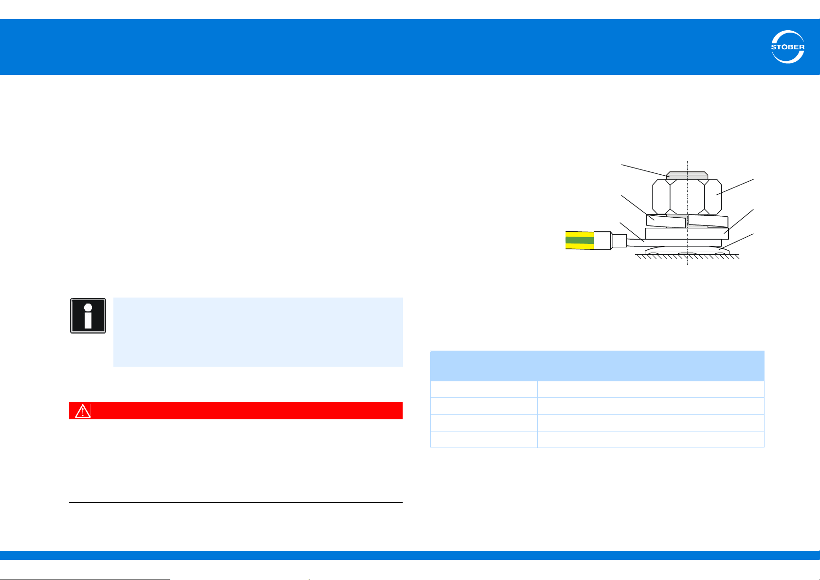
Note the following information on the connection of the protective earth
to ground the housing correctly:
• Note the assembly sequence:
• 1 M6 earth bolt
• 2 Contact disk
• 3 Cable socket
• 4 Washer
• 5 Return spring
(optional)
•6 Nut
Contact disk, washer,
return spring and nuts are supplied with the drive controller.
• Tightening torque: 4 Nm
• Stray currents > 10 mA can arise in normal operation. To fulfill DIN
EN 61800-5-1 and EN 60204-1, connect the earth bolts with a
copper conductor according to the following table:
Cross-section S
Feeder
S ≤ 2.5 mm
2.5 < S ≤ 16 mm
16–35 mm
> 35 mm
2
2.5 mm2
2
≥16 mm2
2
S/2
2
S
Minimum cross-section SP
Earth conductor at earth bolts
ID 442537.01 29WE KEEP THINGS MOVING
Page 30
5
Connecting
Commissioning Instructions SD6
5.5 Drive controller
5.5.1 Overview of terminals
The terminal overview described in this section show the SD6 drive
controller with the following equipment in the pictures:
• Safety technology ST6
• Terminal module XI6
• Communication module EC6 (EtherCAT)
The following equipment is also optionally available as an alternative:
• Terminal module RI6 or IO6
• Communication module CA6 (CANopen)
ID 442537.01 30WE KEEP THINGS MOVING
Page 31
5
Connecting
Commissioning Instructions SD6
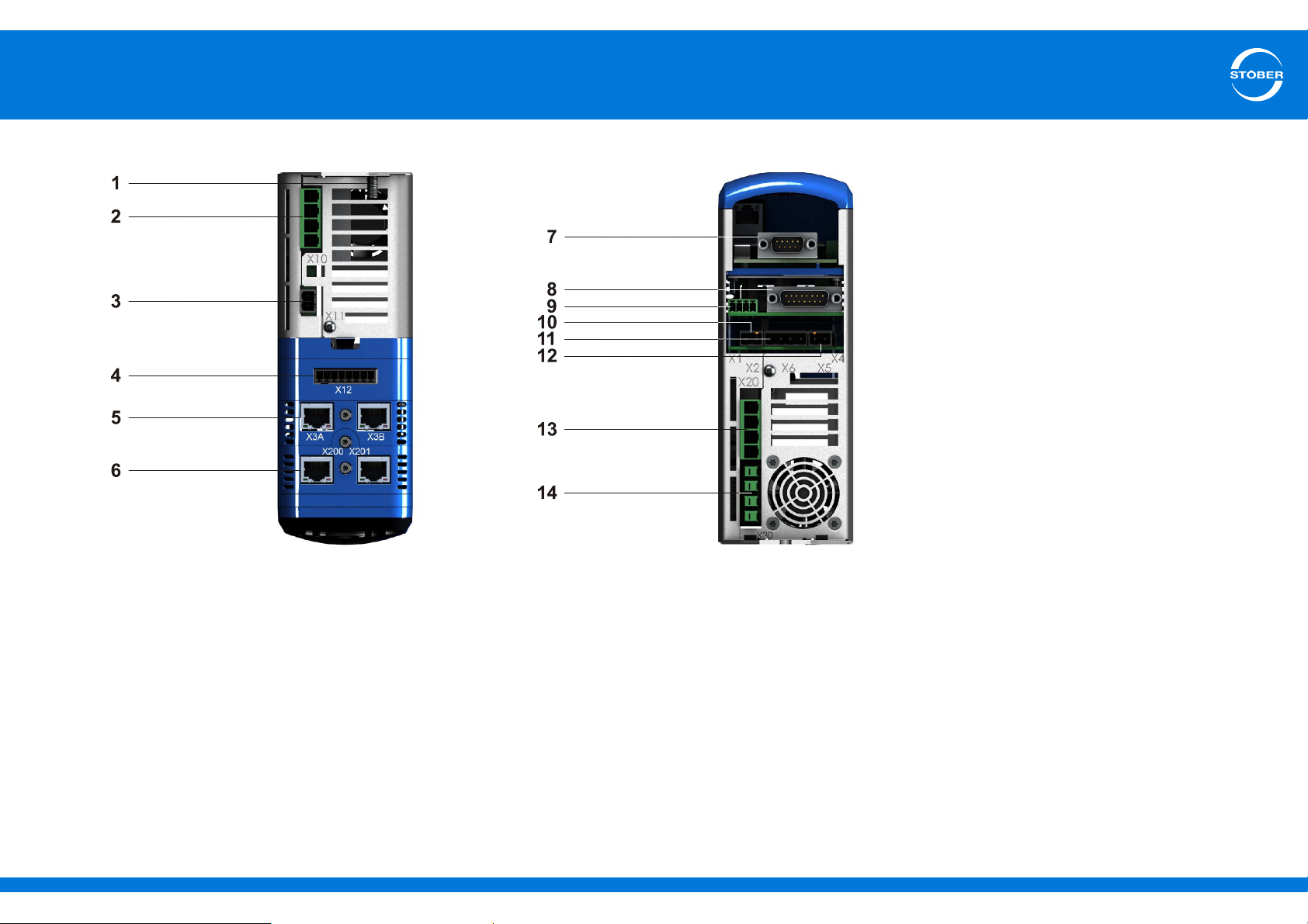
5.5.1.1 Size 0
1 Housing grounding
2 X10: 230 V/400 V power supply
3 X11: 24-V power supply
4 X12: Safety technology (ST6)
5 X3A and X3B: PC, IGB
6 X200 and X201: Optional communication module EtherCAT (EC6)
(X200: CANopen DS-301 (CA6), alternatively available)
7 X120: Encoder connection to optional terminal module XI6
(X120 and X140: Encoder connections to terminal module RI6,
alternatively available)
(Without encoder connection: Terminal module IO6, alternatively available)
ID 442537.01 31WE KEEP THINGS MOVING
8 X4: Encoder
9 X1: Enable and relay 1
10 X2: Motor temperature sensor
11 X6: Motor holding brake (feedback and supply)
12 X5: Motor holding brake (control)
13 X20: Motor
14 X30: Quick DC-Link, braking resistor
Page 32
5
Connecting
Commissioning Instructions SD6
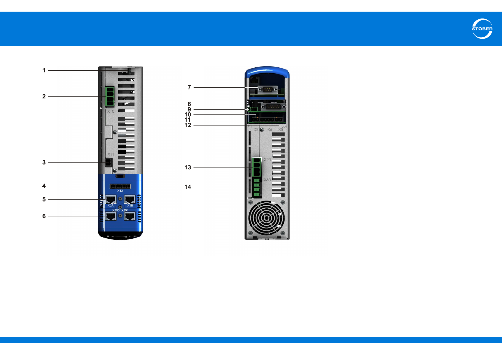
5.5.1.2 Size 1
1 Housing grounding
2 X10: 400 V power supply
3 X11: 24-V power supply
4 X12: Safety technology (ST6)
5 X3A and X3B: PC, IGB
6 X200 and X201: Optional communication module EtherCAT (EC6)
(X200: CANopen DS-301 (CA6), alternatively available)
7 X120: Encoder connection to optional terminal module XI6
(X120 and X140: Encoder connections to terminal module RI6,
alternatively available)
(Without encoder connection: Terminal module IO6, alternatively available)
ID 442537.01 32WE KEEP THINGS MOVING
8 X4: Encoder
9 X1: Enable and relay 1
10 X2: Motor temperature sensor
11 X6: Motor holding brake (feedback and supply)
12 X5: Motor holding brake (control)
13 X20: Motor
14 X30: Quick DC-Link, braking resistor
Page 33
5
Connecting
Commissioning Instructions SD6
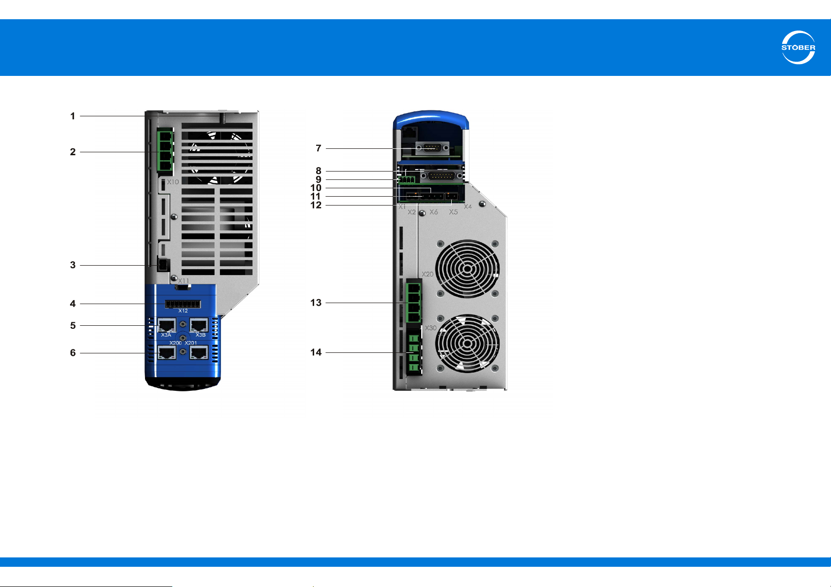
5.5.1.3 Size 2
1 Housing grounding
2 X10: 400 V power supply
3 X11: 24 V power supply
4 X12: Safety technology (ST6)
5 X3A and X3B: PC, IGB
6 X200 and X201: Optional communication module EtherCAT (EC6)
(X200: CANopen DS-301 (CA6), alternatively available)
7 X120: Encoder connection to terminal module XI6
(X120 and X140: encoder connections to optional terminal module RI6,
alternatively available)
(Without encoder connection: Terminal module IO6, alternatively available)
ID 442537.01 33WE KEEP THINGS MOVING
8 X4: Encoder
9 X1: Enable and relay 1
10 X6: Motor holding brake (feedback and supply)
11 X2: Motor temperature sensor
12 X5: Motor holding brake (control)
13 X20: Motor
14 X30: Quick DC-Link, braking resistor
Page 34
5
Connecting
Commissioning Instructions SD6
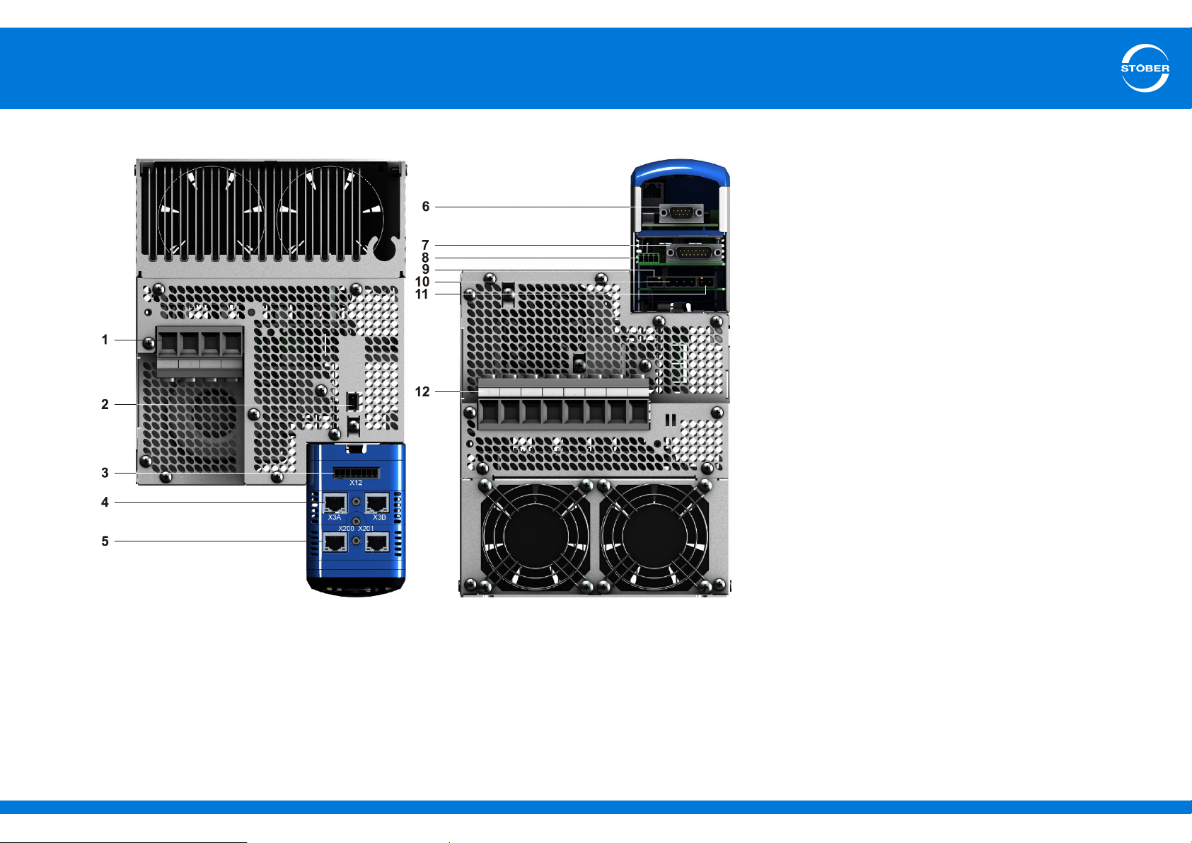
5.5.1.4 Size 3
1 X10: 400 V power supply
2 X11: 24 V power supply
3 X12: Safety technology (ST6)
4 X3A and X3B: PC, IGB
5 X200 and X201: Optional communication module EtherCAT (EC6)
(X200: CANopen DS-301 (CA6), alternatively available)
6 X120: Encoder connection to terminal module XI6
(X120 and X140: encoder connections to optional terminal module RI6,
alternatively available)
(Without encoder connection: Terminal module IO6, alternatively available)
ID 442537.01 34WE KEEP THINGS MOVING
7 X4: Encoder
8 X1: Enable and relay 1
9 X2: Motor temperature sensor
10 X6: Motor holding brake (feedback and supply)
11 X5: Motor holding brake (control)
12 X20: Motor, Quick DC-Link, braking resistor
Page 35
5
12
3
4
Connecting
Commissioning Instructions SD6
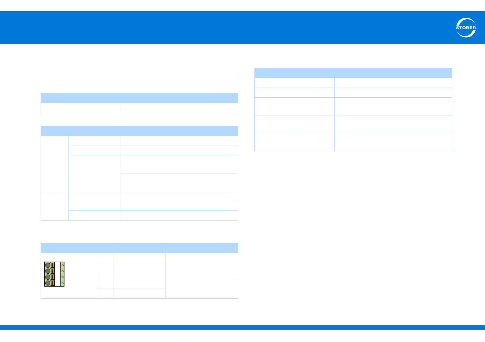
5.5.2 X1: Enable and relay 1
Use the enable signal to enable the power pack of the drive controller.
The function of relay 1 can be adjusted in parameter F75.
General specification
Maximum cable length 30 m
Electrical Data
Relay 1
Enable
U
2max
I
2max
Life expectancy Mechanical: min. of 5,000,000 switching
High level 12 – 30 V
Low level 0 – 8 V
I
16 mA
1max
30 V
1.0 A
operations
At 24 V/1A (ohmic load): 300,000 switching
operations.
Maximum conductor cross-section
Connection type Maximum conductor cross-section [mm2]
Rigid 1.5
Flexible 1.5
Flexible with cable end,
without plastic sleeve
Flexible with cable end, with
plastic sleeve
2 leads with the same cross-
section with double cable end
1.5
0.5
—
Terminal description
Pin Designation Function
1 Contact 1 Relay 1
2 Contact 2
3GND
4 Input
a) Use a 1 A fuse (delayed-action) upstream from relay 1 for fuse protection. Make certain for ULcompliant operation that the fuse has been approved for the requirements of UL 248.
ID 442537.01 35WE KEEP THINGS MOVING
Recommended fuse: max.
a)
1 AT
Enable
Page 36
5
78
Connecting
Commissioning Instructions SD6
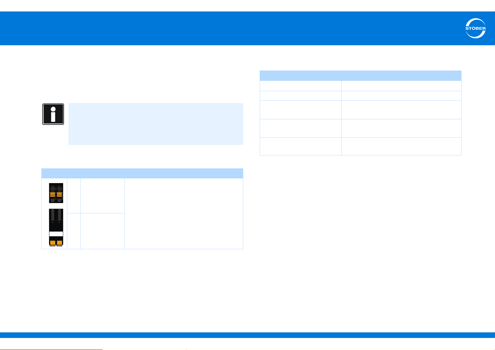
5.5.3 X2: Motor temperature sensor
Terminal X2 is provided for connecting motor temperature sensors. This
means you can connect either one KTY 84 in one winding, one PTC per
winding or up to two PTC drillings for operation with multiple motors.
Information
Note that evaluation of the temperature sensors is always active. If
operation without temperature sensor is permitted, the connections
must be bridged on X2. Otherwise a fault will be triggered when the
device is switched on.
Terminal description X2
Pin Designation Function
7 1TP1/1K1 + Connection of PTC or KTY
8 1TP2/1K2 -
Maximum conductor cross-section
Connection type Maximum conductor cross-section [mm2]
Rigid 2.5
Flexible 2.5
Flexible with cable end,
without plastic sleeve
Flexible with cable end, with
plastic sleeve
2 leads with the same cross-
section with double cable end
2.5
2.5
—
ID 442537.01 36WE KEEP THINGS MOVING
Page 37
5
Connecting
Commissioning Instructions SD6
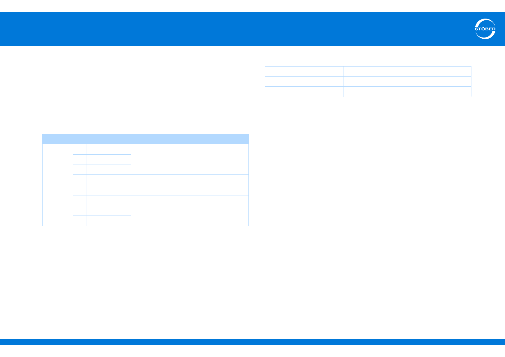
5.5.4 X3A, X3B: PC, IGB
You can implement the functions of the IGB (Integrated Bus) with the
X3A and X3B interfaces:
• Direct connection to the PC
• IGB Motionbus
• Remote maintenance
Terminal description X3A and X3B
Pin Designation Function
1 TxData+ Ethernet communication
2 TxData3 RecvData+
4 — Not used
5—
6 RecvData- Ethernet communication
7 — Not used
8—
It is also possible to use cables with the following specification:
Plug wiring Patch or crossover
Quality CAT5e
Shielding SFTP or PIMF
Cable specification
STOBER provides ready-made cables for
• direct connection of PC drive controllers and
• to set up the integrated bus.
These cables must be used to ensure proper functionality. On this
aspect, pay attention to the section on Accessories.
ID 442537.01 37WE KEEP THINGS MOVING
Page 38
5
Connecting
Commissioning Instructions SD6
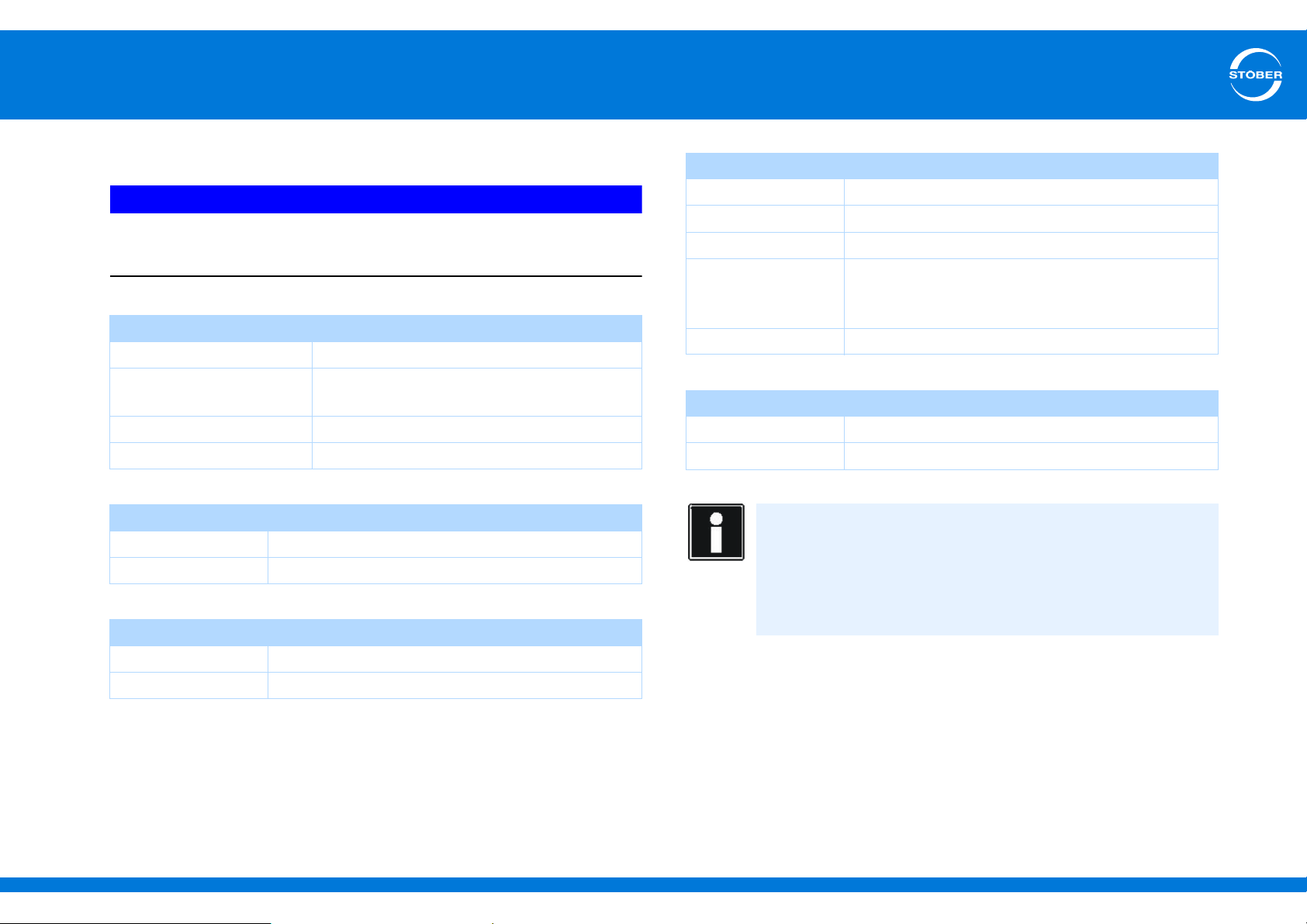
5.5.5 X4: Encoder
NOTICE
Danger of encoder destruction!
X4 may not be connected or disconnected when the device is on!
General specification
U
2
I
2max
I
2min
Maximum cable length 100 m
EnDat 2.1 specification
Encoder type Single and multiturn, not suitable for linear encoders
Clock frequency 2 MHz
EnDat 2.2 specification
Encoder type Single and multiturn
5-15 V (see encoder supply)
X4: 250 mA
Total of X4, X120, X140: 500 mA
13 mA
SSI specification
Clock frequency 250 kHz
Sampling rate 250 µs
Code Binary or Gray
Encoder type and
format
Transfer Double (default setting) or single
Specification for incremental signals
Limit frequency ≤ 1 MHz (evaluation and simulation)
Signal level TTL and HTL
Calculation example – limit frequency
... for encoder with 2,048 pulses per revolution:
3000 revolutions per minute (equivalent to 50 revolutions per
second) * 2048 pulses per revolutions
= 102,400 pulses per second
= 102.4 kHz << 1 MHz
Multiturn: 24 or 25 bits
Single-turn: 13 bits short or 13 bits tree
(13 bits of data in a 25-bit telegram)
Clock frequency 4 MHz
ID 442537.01 38WE KEEP THINGS MOVING
Page 39
5
9
15
1
8
Connecting
Commissioning Instructions SD6
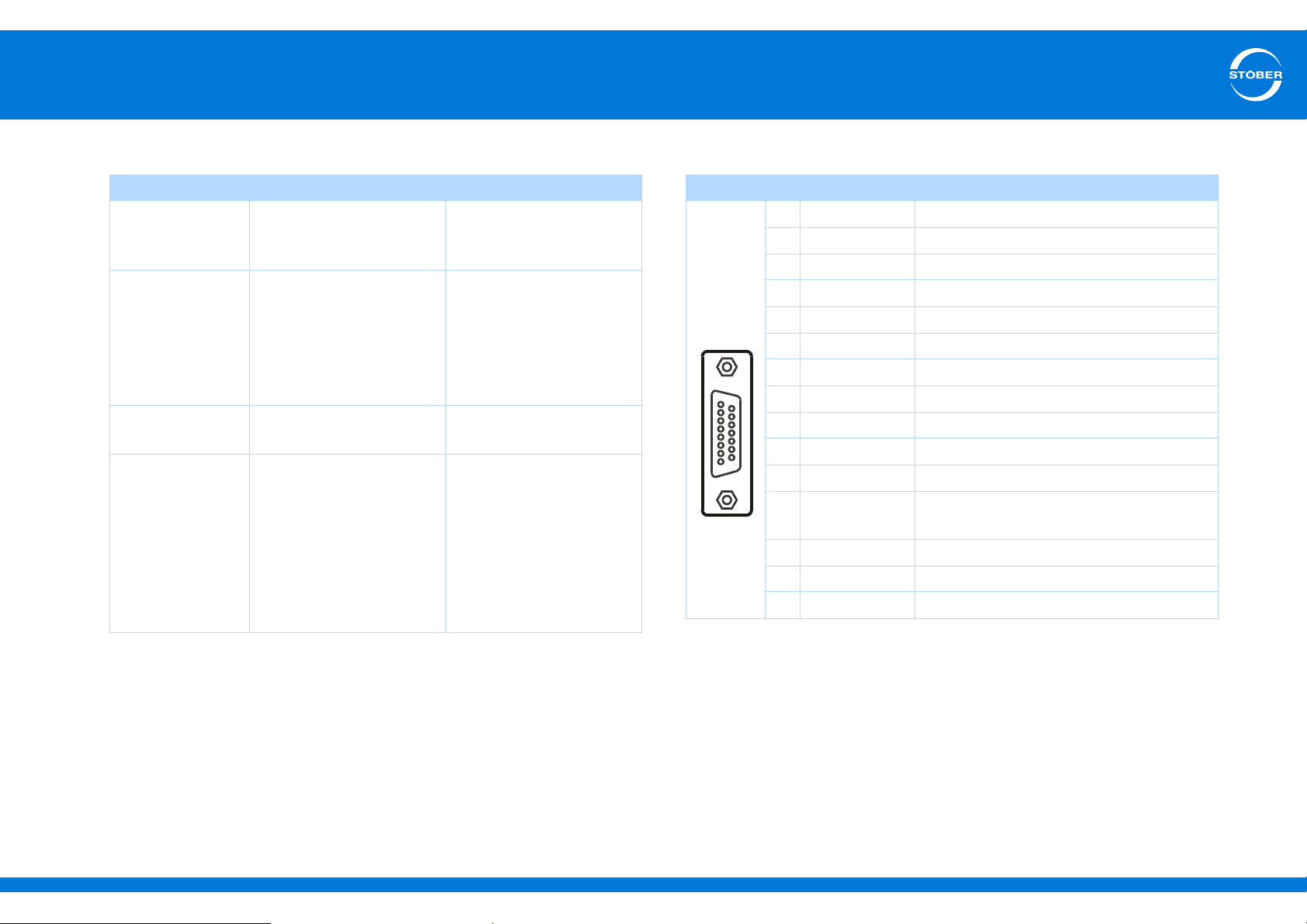
Encoder supply Terminal description X4 – EnDat and SSI encoders
U
2
5 V
(controlled at the
encoder)
5 V
(controlled at X4)
10 V
(unregulated)
15 V
(controlled at X4)
Through
Encoder sense line
connected to pin 12 (sense)
Pin 12 (sense) bridged with
pin 4 (UB+)
Pin 12 (sense) bridged with
pin 2 (GND)
STOBER synchronous
servo motors
Standard: EnDat 2.1/2.2
STOBER asynchronous
motors
TTL (for customer-specific
solutions),
without cable
compensation
Pin 12 (sense) not used
STOBER asynchronous
motors
HTL encoder: Bridge
created in the cable plug
that is connected to X4
SSI encoder: Bridge for
UB+ is created in the
bracket flange socket
Pin Designation Function
1— —
Socket
2 GND Reference for encoder power on pin 4
3— —
4U
2
Encoder power
5 DATA+ Differential input for DATA
6— —
7— —
8 CLK+ Differential input for CLOCK
9— —
10 — —
11 — —
12 Sense Sensor lead for power supply to settle the
encoder power
13 DATA- Inverse, differential input for DATA
14 — —
15 CLK- Inverse, differential input for CLOCK
ID 442537.01 39WE KEEP THINGS MOVING
Page 40
5
9
15
1
8
9
15
1
8
Connecting
Commissioning Instructions SD6
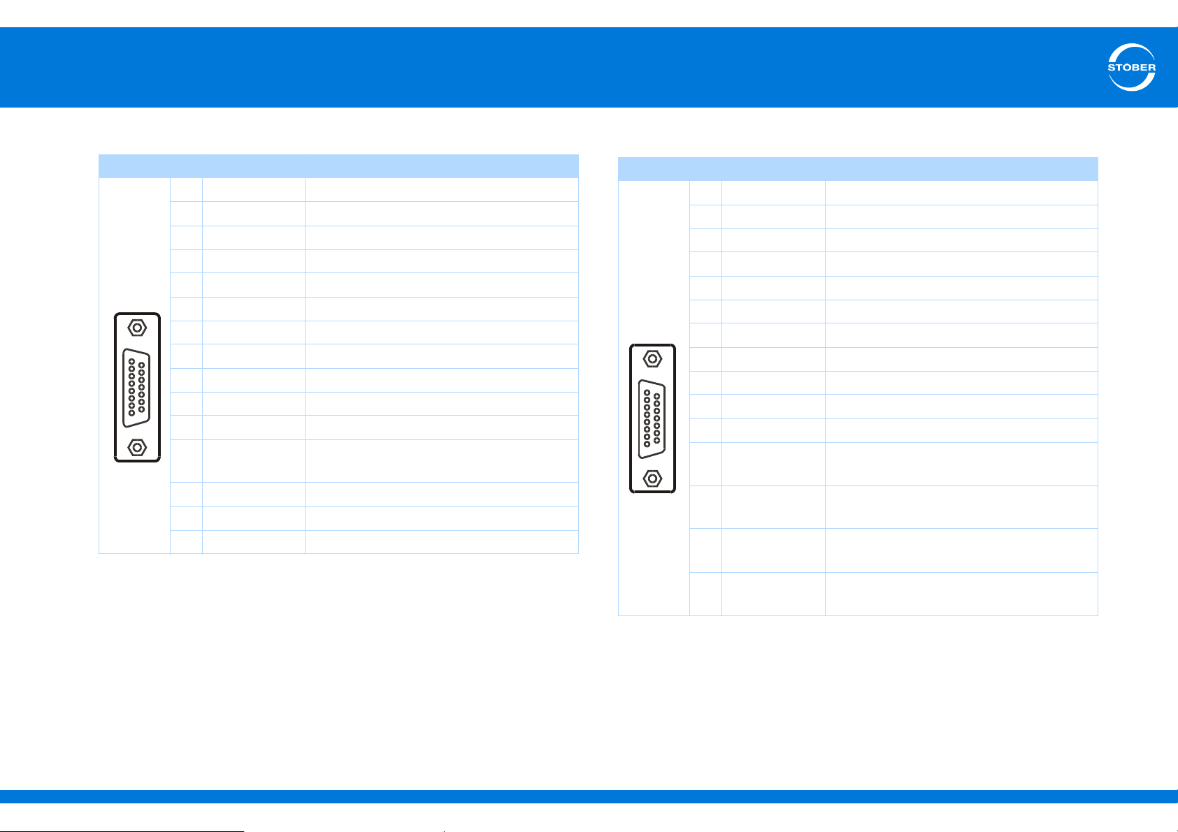
Terminal description X4 for HTL encoder
Pin Designation Function, data
Socket
1 B+ Differential input for B-track
2 GND Reference for encoder power on pin 4
3 N+ Differential input for N-track
4U
2
Encoder power
5— —
6 A+ Differential input for A-track
7— —
8— —
9 B- Inverse, differential input for B-track
10 N- Inverse, differential input for N-track
11 A- Inverse, differential input for A-track
12 Sense Sensor lead for power supply to settle the
encoder power
13 — —
14 — —
15 — —
Terminal description X4 for TTL encoder
Pin Designation Function, data
1— —
Socket
2 GND Reference for encoder supply to pin 4
3— —
4U
2
Encoder supply
5 B+ Differential input for B channel
6— —
7 N+ Differential input for N channel
8 A+ Differential input for A channel
9— —
10 — —
11 — —
12 Sense Sensor line for the supply voltage to adjust
the encoder supply
13 B- Inverse, differential input for
B channel
14 N- Inverse, differential input for
N channel
15 A- Inverse, differential input for
A channel
ID 442537.01 40WE KEEP THINGS MOVING
Page 41
5
56
1_+2
Connecting
Commissioning Instructions SD6
5.5.6 X5, X6: Motor holding brake
Information
Note that motor holding brakes from other manufacturers may only
be connected after consultation with STOBER.
Electrical data
U
1
I
Bmax
Brake
Maximum
switching
frequency
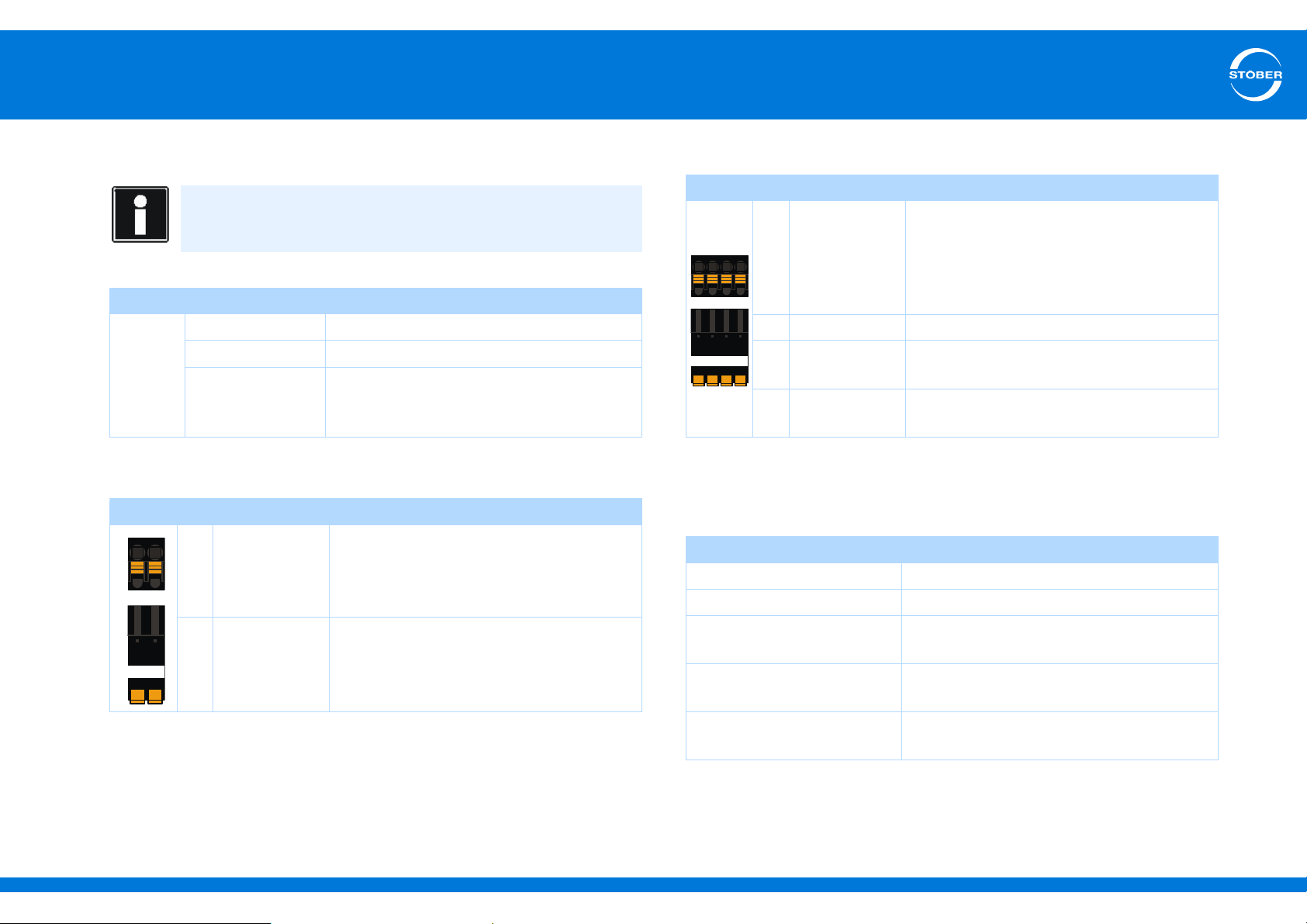
Terminal description X5
Pin Designation Function
5 1BD1 Control brake
6 1BD2 Reference potential
24 – 30 V
3.0 A
1 Hz
Terminal description X6
Pin Designation Function
1 Acknowledge-
ment
2 GND Reference potential for acknowledgement
+ + 24 V Power supply voltage for the brake
- GND Reference potential for power supply voltage
a) Use of a 4 A fuse (slow-blow) is mandatory for a UL-compliant application. The fuse must be
approved according to UL 248.
Maximum conductor cross-section
Connection type Maximum conductor cross-section [mm2]
Rigid 2.5
Flexible 2.5
Flexible with cable end,
without plastic sleeve
Acknowledgement input of an optional
switching amplifier for brake diagnostics –
provided the holding brake is connected to
the SD6 indirectly (for example via a coupling
contactor)
Recommended fuse: max. 6 AT
of the brake
2.5
a)
Flexible with cable end, with
plastic sleeve
2 leads with the same crosssection with double cable end
ID 442537.01 41WE KEEP THINGS MOVING
2.5
—
Page 42
5
L1
N
PE
L1 L2
L3
PE
L1 L2
L3
PE
L1 L2
L3
PE
L1L2
L3
PE
Connecting
Commissioning Instructions SD6
5.5.7 X10: 230 V/400 V power
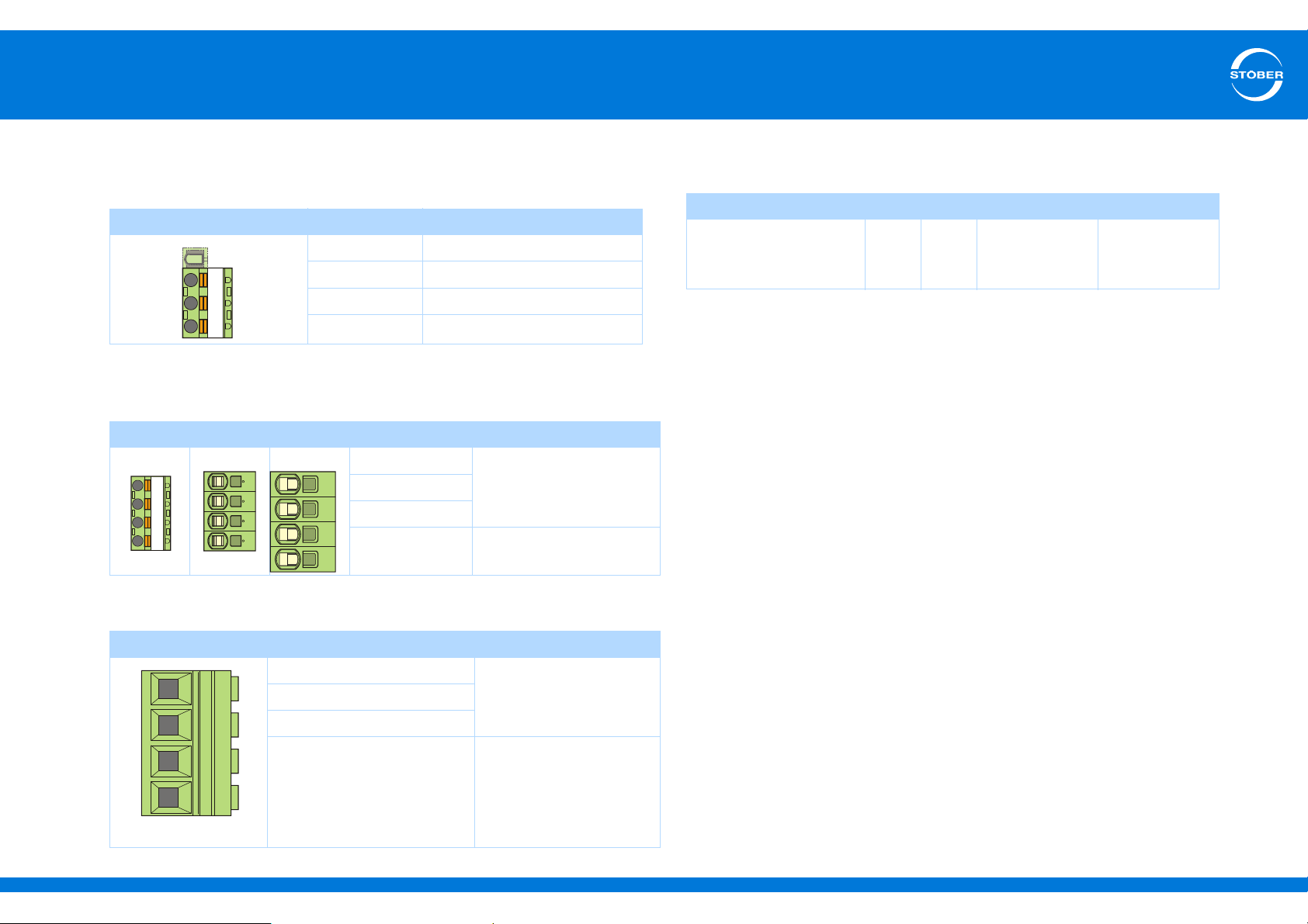
Terminal description – single-phase power connection size 0
Pin Designation Function
— Plastic dummy plug
L1 Input voltage
N Neutral conductor
PE Protective ground
Terminal description – three-phase power supply connection
size 0, size 1 and size 2
Pin Designation Function
Size 0 Size 1 Size 2 L1
Input voltageL2
L3
PE Protective ground
Maximum conductor cross-section of power supply connection
terminals
Size Size 0 Size 1 Size 2 Size 3
Max. cross-section for
conductor with ferrule
2
[mm
]
2.5 4
6
(10 for rigid
conductors)
25
(35 for rigid
conductors)
Terminal description – three-phase power supply connection size 3
Pin Designation Function
L1
Input voltageL2
L3
PE Protective ground
ID 442537.01 42WE KEEP THINGS MOVING
Page 43
5
+
_
Connecting
Commissioning Instructions SD6
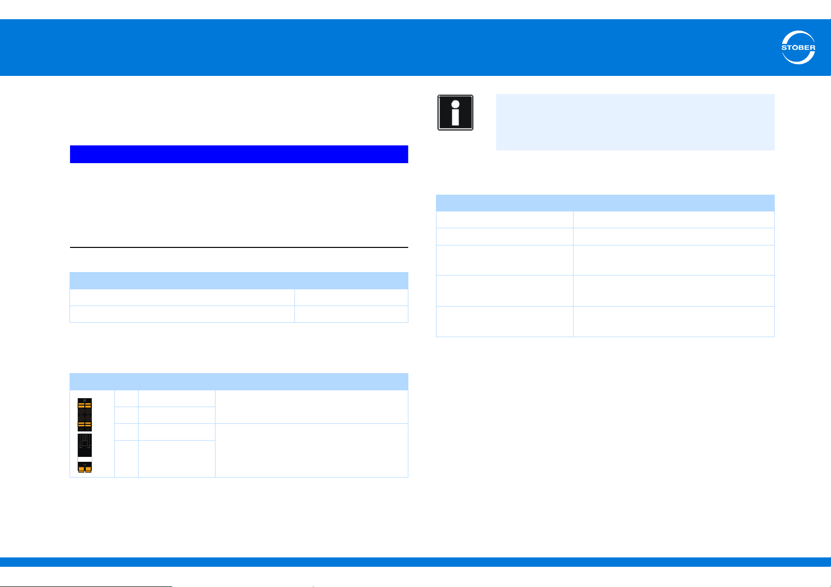
5.5.8 X11: 24 V power
Connection of 24 V to X11 is required for powering the control part.
NOTICE
Device damage due to overload!
If the 24-V supply is looped to multiple devices via terminal X11, the
device may be damaged by a current that is too high.
Make certain that the current via terminal X11 does not exceed 15 A
(UL: 10 A).
Control board
U
1
a)
I
1max
a) depending on the accessories used
Terminal description X11
Pin Designation Function
++ 24 V
++ 24 V
–GND
–GND
Auxiliary voltage (PELV) for control
electronics supply; bridged in the terminal
Reference potential for + 24 V; bridged in
the terminal
20.4 – 28.8 V
1.5 A
Information
The drive controller must not be connected to a DC mains power
supply. Supply the drive controller instead with a local 24 V DC
power supply.
Maximum conductor cross-section
Connection type Maximum conductor cross-section [mm2]
Rigid 2.5
Flexible 2.5
Flexible with cable end,
without plastic sleeve
Flexible with cable end, with
plastic sleeve
2 leads with the same cross-
section with double cable end
2.5
2.5
—
ID 442537.01 43WE KEEP THINGS MOVING
Page 44
5
1
2345678
Connecting
Commissioning Instructions SD6
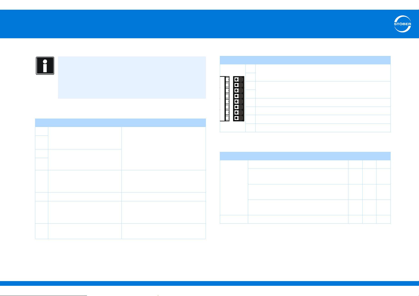
5.5.9 X12: Safety technology
Information
Please note:
If you will be using the safety function, make certain to read the ST6
manual (see section 1.2 Other manuals).
If you do not want to use the safety function, connect 24 V to
X12.STO
Electrical data
Pin Designation/function Data
1
STO
(bridged internally)
2
3
4
5GND for STO
6STO
7GND for STO
8 Power supply of STO
a
(bridged internally)
STO
b
(bridged internally with terminal
7)
status
(bridged internally with terminal
5)
and X12 STOb, for example by connecting X11.
a
U
1max
High level = 12–30 V
Low level = 0–8 V
I
1max
I
Max terminal
C
= 100 nF
1
and STOb
a
—
U2 = U1 - (200 mΩ * I1)
and STOb
a
status
—
U1 = 18–28.8 V
I
1max
= 30 VDC (PELV)
= 100 mA (< 30 mA at 24 V)
= 4 A
DC
= 100 mA
Terminal description X12
Pin Designation/function
1
STO
(bridged internally)
2
a
3
STO
(bridged internally)
4
5GND for STO
6STO
b
Status
and STOb (bridged internally with terminal 7)
a
7GND for STOa and STOb (bridged internally with terminal 5)
8 Supply of STO
Status
Cable requirements
Feature Line type Unit Min Max
mm
mm
2
0.14 1
2
0.2 1
2
0.2 1
Crosssection
Fine wire line without cable end sleeve mm
Fine wire line
with cable end sleeve without plastic collar
Fine wire line
with cable end sleeve and plastic collar
according to AWG AWG26 18
Length — m — 30
ID 442537.01 44WE KEEP THINGS MOVING
Page 45
5
UV
W
PE
UV
W
PE
UV
W
PE
R- R+ W V U D- D+ PE
Connecting
Commissioning Instructions SD6
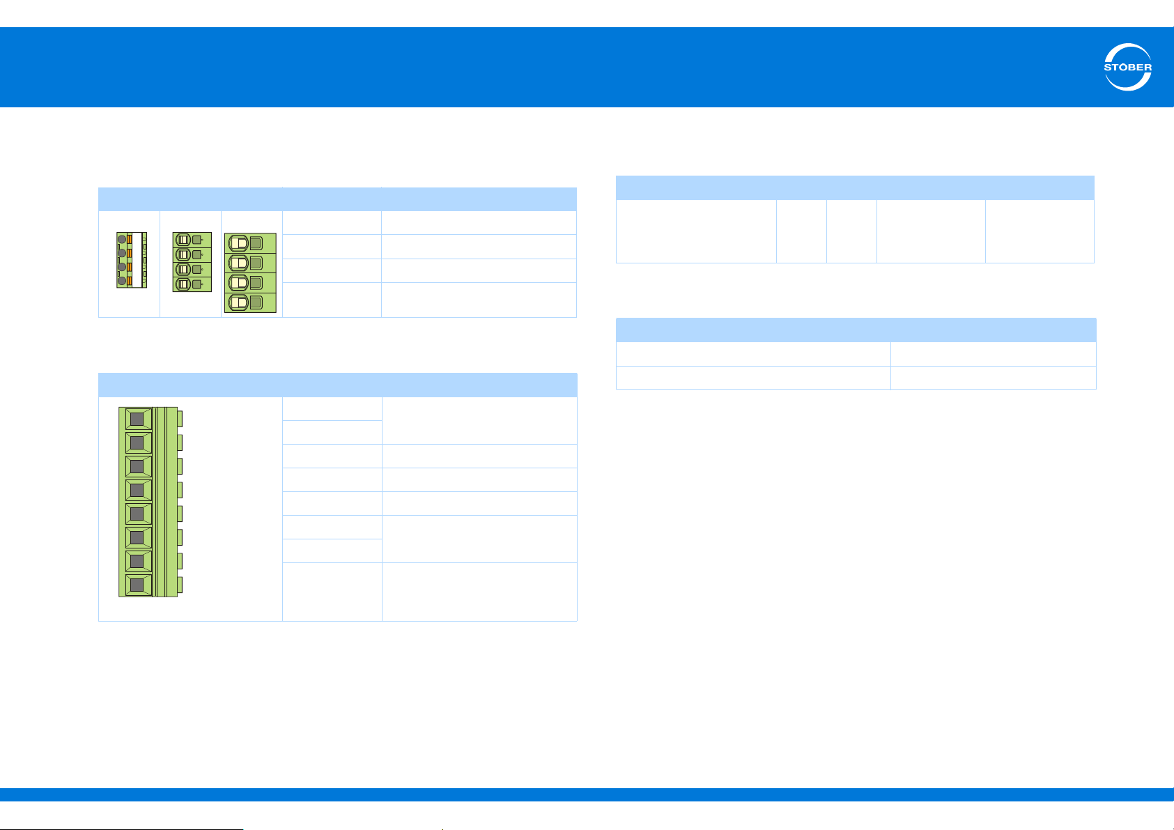
5.5.10 X20: Motor
Terminal description X20 – size 0, size 1, size 2
Pin Designation Function
Size 0 Size 1 Size 2 U Motor connection phase U
V Motor connection phase V
W Motor connection phase W
PE Protective ground
Terminal description X20 – size 3
Pin Designation Function
RR+
W Motor connection phase W
V Motor connection phase V
U Motor connection phase U
DD+
PE Protective ground
Brake resistor
DC link (Ger. Zwischenkreis)
Maximum conductor cross-section of power supply connection
terminals
Size Size 0 Size 1 Size 2 Size 3
Max. cross-section for
conductor with ferrule
2
[mm
]
2.5 4
6
(10 for rigid
conductors)
25
(35 for rigid
conductors)
Maximum motor cable length
Size Size 0 to Size 2
Without output derater 50 m
With output choke 100 m
Connection without output choke
Observe the following points when connecting the motor without the
output choke:
• Ground the shield of the motor cable with the shield connection
clamp on the EMC shroud.
• Keep the exposed conductor as short as possible. All devices and
circuits that are sensitive to EMC must be kept at a distance of at
least 0.3 m.
ID 442537.01 45WE KEEP THINGS MOVING
Page 46
5
Pin 7 and
8 are
bridged at
the output
derator
1U1 1U2 1V1 1V2
1W1
1W2
7PE8
PE
Connecting
Commissioning Instructions SD6
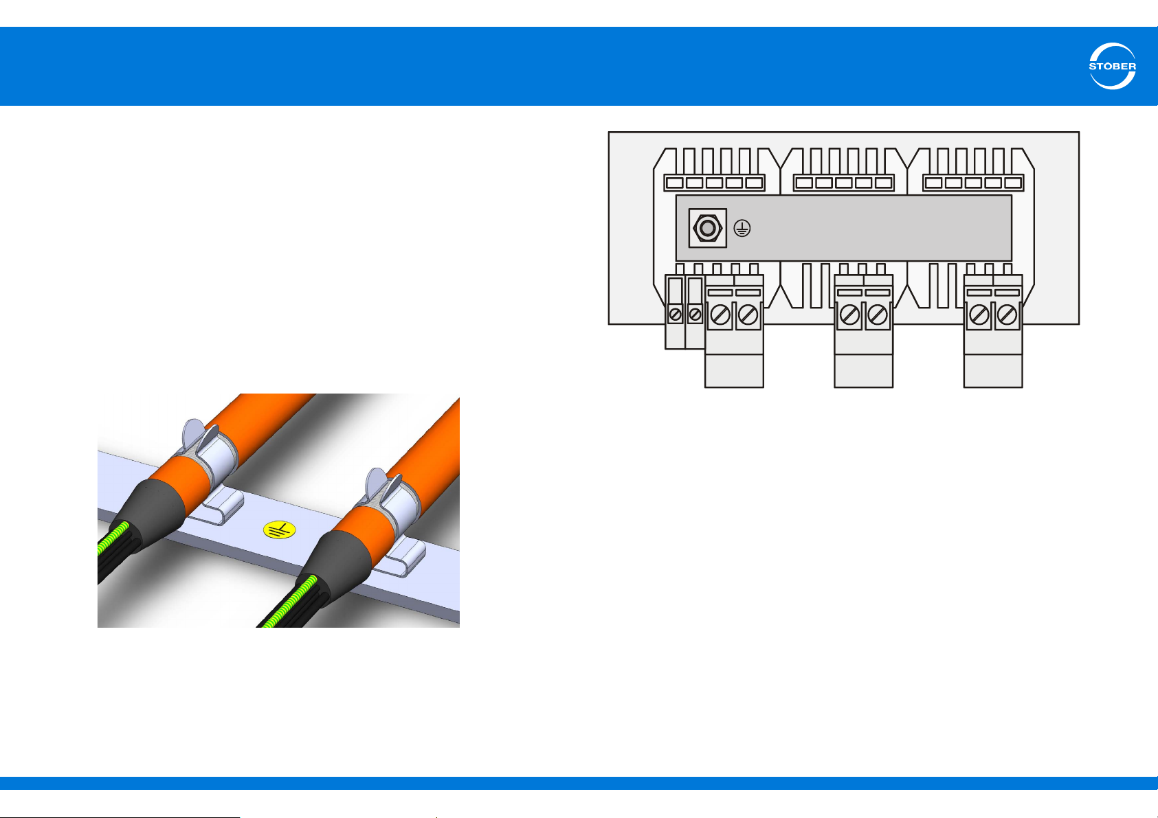
Connection with output choke
Observe the following points when connecting the motor to the output
choke:
• Ground the shield of the motor cable with large area contacts in the
immediate vicinity of the output choke, for example with electrically
conductive metal cable terminals on a grounded connection rail.
• Keep the exposed conductor as short as possible. All devices and
circuits that are sensitive to EMC must be kept at a distance of at
least 0.3 m.
Example of the shield connection of the motor cable when connecting
the motor with an output choke (graphic: icotek GmbH):
ID 442537.01 46WE KEEP THINGS MOVING
Page 47
5
D- D+
R+
R-
D-
D+
R+
R-
D- D+
R+
R-
Connecting
Commissioning Instructions SD6
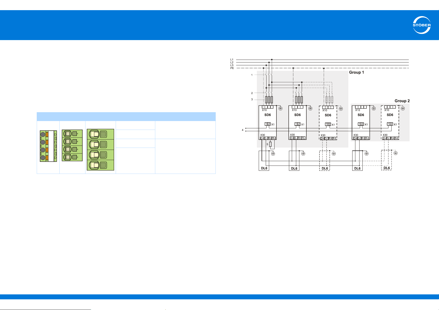
5.5.11 X30: Quick DC-Link, braking resistor
Terminal X30 is available for connecting a braking resistor and – in the
case of a Quick DC-Link – for connecting a drive controller with module
DL6.
Regarding the structure of Quick DC-Link, please refer to the SD6
manual (see section 1.2 Other manuals).
Terminal description X30
Pin Designation Function
Size 0 Size 1 Size 2 D-
DC link
D+
R+
R-
Braking resistor
Principal circuit diagram
Caption
1 Power contactor
2 Circuit breaker
3 Short circuit protection
4 Relay 1:
Must be integrated into the control unit! Note the parameterization of the
relay in F75.
5 Braking resistor: Dimension the braking resistor according to the braking
output of the Quick DC-Link and the technical data of the drive controller.
ID 442537.01 47WE KEEP THINGS MOVING
Page 48
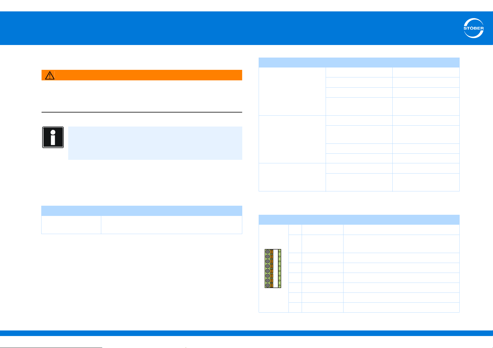
5
1
2
3
4
5
6
7
8
Connecting
Commissioning Instructions SD6
5.6 Terminal modules
WARNING!
Danger of faulty machine behavior due to EMC faults!
Use exclusively cables up to 30 m in length for analog and binary
inputs and outputs (AE, AA, BE, BA)!
Information
Note that the sampling time and refresh rate T
and outputs depend on parameter A150 cycle time (corresponding
values: at least 1 ms).
5.6.1 X100
X100 specification
General specification
Maximum cable
length
30 m, shielded
of the inputs
a_min
Electrical data
Analog inputs
AE1 and AE2
Analog input
AE1 as current input
(AE1+ and AE1- shunt
bridged)
Analog outputs
AA1 and AA2
Level ±10 V
Resolution 16 bits
Internal resistance > 40 kΩ
Refresh rate Cycle time of the
Level ±20 mA
Resolution IO6: 12 bits
Internal resistance 492 Ω
Wire break monitoring Parameterizable in F15
Level ±10 V
Maximum output current XI6: 10 mA
Terminal description X100
Pin Designation Function
1 AE1+ + Input of the analog input AE1
2 AE1-Shunt Current input; shunt connection Pin 2 must
be jumpered with pin 1.
3 AE1- Inverted input of analog input AE1
4 AE2+ + Input of analog input AE2
application
XI6, RI6: 16 bits
IO6, RI6: ± 20 mA
5 AE2- Inverted input of analog input AE2
6 AA1 Analog output 1
7 AA2 Analog output 2
ID 442537.01 48WE KEEP THINGS MOVING
8 AGND Reference ground
Page 49
5
Connecting
Commissioning Instructions SD6
Maximum conductor cross-section
Connection type Maximum conductor cross-section [mm2]
Rigid 1,5
Flexible 1,5
Flexible with cable end,
without plastic sleeve
Flexible with cable end, with
plastic sleeve
2 leads with the same cross-
section with double cable end
1,5
0,5
—
5.6.2 X101
X101 specification
General specification
Maximum cable length 30 m, shielded
Electrical data
Binary inputs
BE1 to BE3
Binary inputs
BE4 and BE5
Binary outputs
BA1 and BA2
Low level 0–8 V
High level 12–30 V
Input voltage Max. 30 V
Input current Max. 16 mA
Input frequency Max. 10 kHz
Low level 0–8 V
High level 12–30 V
Input voltage Max. 30 V
Input current Max. 16 mA
Input frequency XI6: max. 100 kHz
Maximum output current XI6: 50 mA
Typical voltage drop < 2 V
Refresh rate Cycle time of the
Output frequency Max. 250 kHz
IO6, RI6: max. 250 kHz
IO6, RI6: 100 mA
application (at least 1
ms)
24 vdc power supply Input voltage 18–28.8 V
ID 442537.01 49WE KEEP THINGS MOVING
Page 50
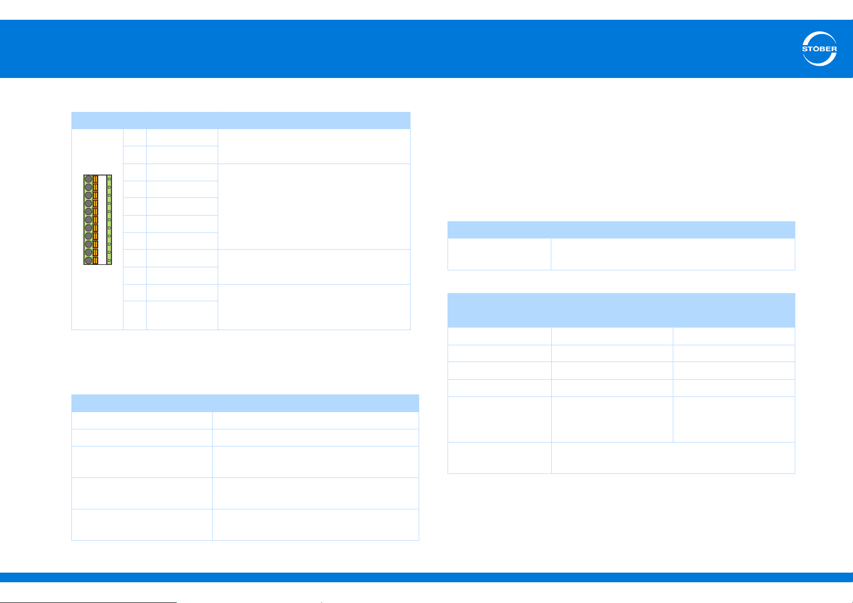
5
9
10
11
12 13 14 15 16 17 18 19
Connecting
Commissioning Instructions SD6
Terminal description X101 for binary signals BE encoder and BA encoder simulation
Pin Designation Function
9DGND
10 DGND
11 BE1
12 BE2
13 BE3
14 BE4
15 BE5
16 BA1
17 BA2
18 24 V-In 24-V supply for all binary outputs and
19 24 V-In
a) Use a 1 A fuse (delayed-action) upstream from relay 1 for fuse protection. Make certain for
UL-compliant operation that the fuse has been approved for the requirements of UL 248.
Maximum conductor cross-section
Connection type Maximum conductor cross-section [mm2]
Rigid 1.5
Flexible 1.5
Flexible with cable end,
without plastic sleeve
Flexible with cable end, with
plastic sleeve
2 leads with the same cross-
section with double cable end
Reference ground
Binary input
Binary output
binary inputs BE6 to BE13.
Recommended fuse: max. 1 AT
1.5
0.5
—
a)
To be able to simulate or evaluate encoders on binary interfaces, you
must place one of the terminal modules XI6, RI6 or IO6 in operation.
To evaluate single-ended incremental encoder or stepper motor signals,
use binary inputs BE3, BE4 and BE5. If you would like to simulate them,
use outputs BA1 and BA2.
Hall encoders are connected to binary inputs BE1, BE2 and BE3.
General specification
Maximum cable
length
Evaluation – incremental and stepper motor signals
High level 12–30 V 2–6 V
Low level 0–8 V 0– 0.8 V
U
E max
I
E max
Limit frequency 100 kHz if High level > 15
T
a_min
30 m, shielded
HTL TTL
30 V 6 V
16 mA 13 mA
250 kHz
V and external push pull
configuration
Cycle time of the application with time stamp
correction (resolution 1 µs)
ID 442537.01 50WE KEEP THINGS MOVING
Page 51
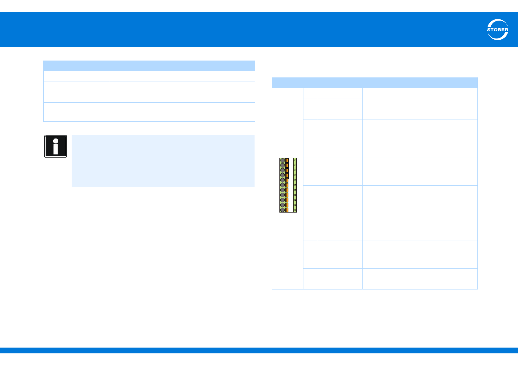
5
9
10
11
12 13 14 15 16 17 18 19
Connecting
Commissioning Instructions SD6
Simulation – incremental and stepper motor signals
I
2max
Eff. update rate 4 kHz
Limit frequency 250 kHz
Extrapolation
frequency
Calculation example – limit frequency
... for encoder with 2,048 pulses per revolution:
3000 revolutions per minute (equivalent to 50 revolutions per
second) * 2048 pulses per revolution
= 102,400 pulses per second
= 102.4 kHz
XI6: 50 mA, RI6 and IO6: 100 mA
66 MHz
Terminal description X101 incremental encoders and stepper
motor signals
Pin Designation Function
9DGND
Reference ground, bridged internally
10 DGND
11 BE1 —
12 BE2 —
13 BE3 Evaluation
Incremental encoder: N
Stepper motor signals: –
14 BE4 Evaluation
Incremental encoder: A
Stepper motor signals: Frequency
15 BE5 Evaluation
Incremental encoder: B
Stepper motor signals: direction
16 BA1 Simulation
Incremental encoder: A
Stepper motor signals: Frequency
17 BA2 Simulation
Incremental encoder: B
Stepper motor signals: direction
18 24 V-In
19 24 V-In
ID 442537.01 51WE KEEP THINGS MOVING
24-V supply, bridged internally
Page 52
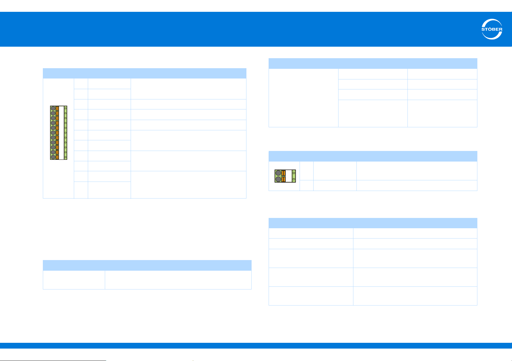
5
9
10
11
12 13 14 15 16 17 18 19
12
Connecting
Commissioning Instructions SD6
Terminal description X101 for Hall sensor signals
a)
Pin
a) Connection to LA6, terminal X302.
b) Use a 1 A fuse (delayed-action) upstream from relay 1 for fuse protection. Make certain for
UL-compliant operation that the fuse has been approved for the requirements of UL 248.
Designation Function
9DGND
10 DGND
11 BE1 HALL A
12 BE2 HALL B
13 BE3 HALL C
14 BE4
15 BE5
16 BA1
17 BA2
18 24 V-In 24-V supply for all binary outputs and
19 24 V-In
Reference ground
Binary input
Binary output
binary inputs BE6 to BE13.
Recommended fuse: max. 1 AT
b)
5.6.3 X102
X102 specification
General specification
Maximum cable
length
30 m, shielded
Electrical data
Analog input AE3 Level ±10 V
Resolution 16 bits
Internal resistance > 40 kΩ
Refresh rate Cycle time of the
application (at least 1
ms)
Terminal description X102
Pin Designation Function
1 AE3+ + input of analog input AE3
Differential input voltage
2 AE3- Inverted input of analog input AE3
Maximum conductor cross-section
Connection type Maximum conductor cross-section [mm2]
Rigid 1.5
Flexible 1.5
Flexible with cable end,
without plastic sleeve
Flexible with cable end, with
plastic sleeve
2 leads with the same cross-
section with double cable end
1.5
0.5
—
ID 442537.01 52WE KEEP THINGS MOVING
Page 53
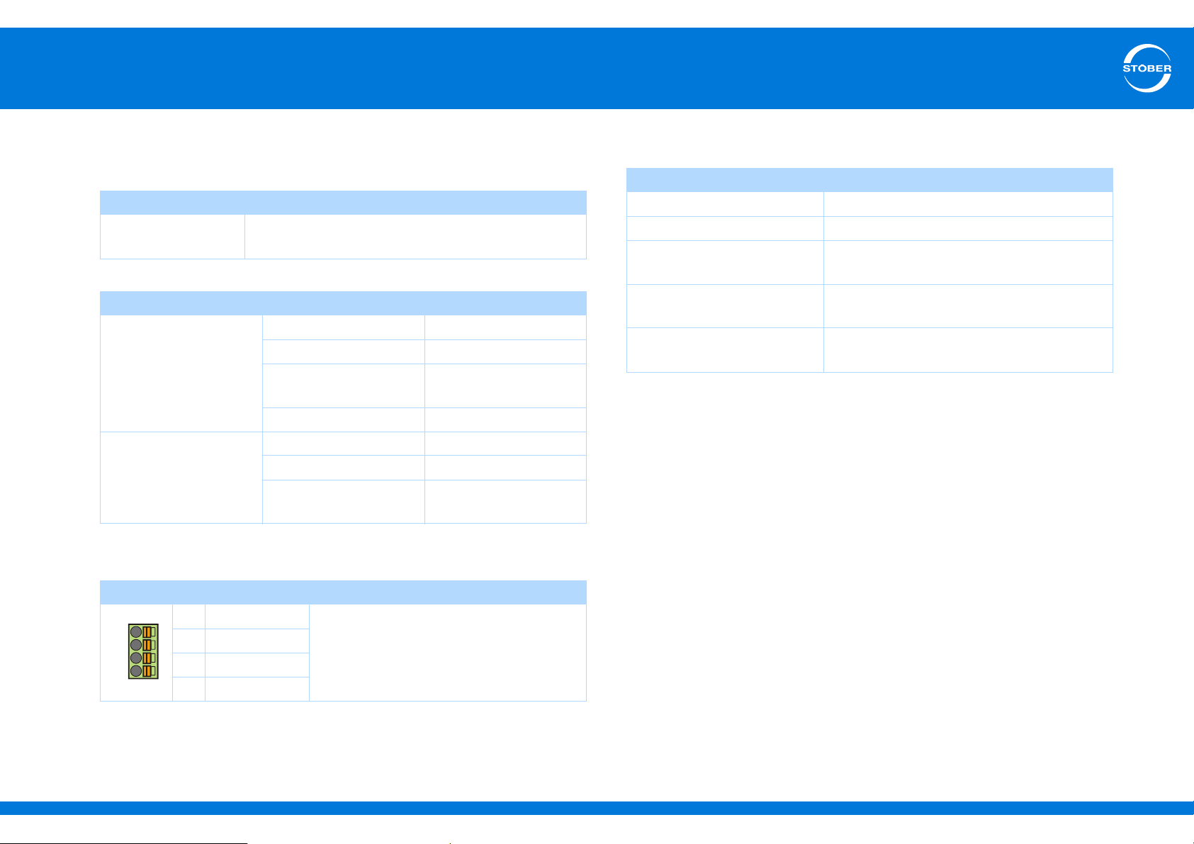
5
4
1
2
3
Connecting
Commissioning Instructions SD6
5.6.4 X103A
X103A specification
General specification
Maximum cable
length
Electrical data
Binary outputs
BA3 and BA4
Binary outputs
BA5 and BA6
30 m, shielded
Maximum output current 50 mA
Typical voltage drop < 2 V
Refresh rate Cycle time of the
application
Inductive load Max. 1.2 VA
Maximum output current 50 mA
Typical voltage drop < 2 V
Refresh rate Cycle time of the
application
Maximum conductor cross-section
Connection type Maximum conductor cross-section [mm2]
Rigid 1.5
Flexible 1.5
Flexible with cable end,
without plastic sleeve
Flexible with cable end, with
plastic sleeve
2 leads with the same cross-
section with double cable end
1.5
0.75
—
Terminal description X103A
Pin Designation Function
1 BA3
2 BA4
3 BA5
4 BA6
ID 442537.01 53WE KEEP THINGS MOVING
Binary output
Page 54
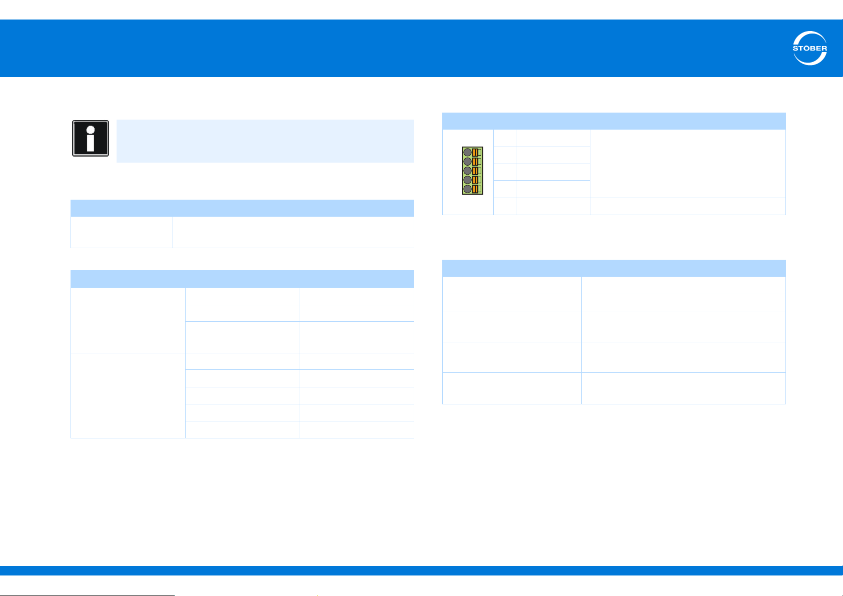
5
9
7
8
5
6
Connecting
Commissioning Instructions SD6
5.6.5 X103B
Information
When the 24 V power fails, binary inputs BE6 to BE13 have signal
status 0 (regardless of the physical signal state).
X103B specification
General specification
Maximum cable
length
Electrical data
Binary outputs
BA7 to BA10
Binary input BE6 Low level 0–8 V
30 m, shielded
Maximum output current 50 mA
Typical voltage drop < 2 V
Refresh rate Cycle time of the
application
High level 12–30 V
Input voltage Max. 30 V
Terminal description X103B
Pin Designation Function
5 BA7
6 BA8
7 BA9
8 BA10
9 BE6 Binary input
Maximum conductor cross-section
Connection type Maximum conductor cross-section [mm2]
Rigid 1.5
Flexible 1.5
Flexible with cable end,
without plastic sleeve
Flexible with cable end, with
plastic sleeve
2 leads with the same cross-
section with double cable end
Binary output
1.5
0.75
—
Input current Max. 16 mA
Input frequency Max. 3 kHz
ID 442537.01 54WE KEEP THINGS MOVING
Page 55
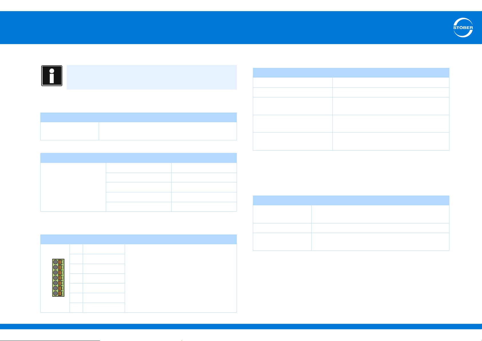
5
10
11
12
13
14
15
16
Connecting
Commissioning Instructions SD6
5.6.6 X103C
Information
When the 24 V power fails, binary inputs BE6 to BE13 have signal
status 0 (regardless of the physical signal state).
X103C specification
General specification
Maximum cable
length
Electrical data
Binary inputs
BE7 to BE13
30 m, shielded
Low level 0–8 V
High level 12–30 V
Input voltage Max. 30 V
Input current Max. 16 mA
Input frequency Max. 3 kHz
Maximum conductor cross-section
Connection type Maximum conductor cross-section [mm2]
Rigid 1.5
Flexible 1.5
Flexible with cable end,
without plastic sleeve
Flexible with cable end, with
plastic sleeve
2 leads with the same cross-
section with double cable end
1.5
0.75
—
5.6.7 X120
Encoder connection X120 is an integral part of terminal modules XI6
and RI6.
General specification
U
2
15 V (see encoder supply)
Terminal description X103C
Pin Designation Function
10 BE7
11 BE8
12 BE9
13 BE10
14 BE11
15 BE12
ID 442537.01 55WE KEEP THINGS MOVING
16 BE13
Binary input
I
2max
Maximum cable
length
250 mA, sum X4, X120, X140: 500 mA
50 m
Page 56
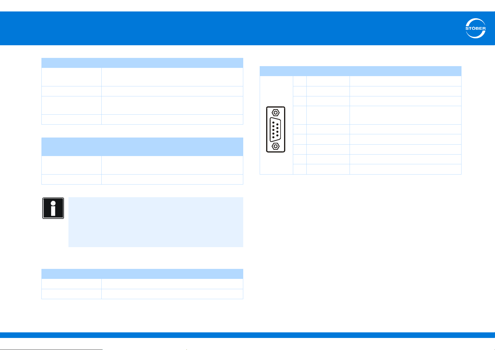
5
5
1
9
6
Connecting
Commissioning Instructions SD6
Specification SSI (evaluation and simulation)
Cycle frequency (SSI
master)
Code Binary or Gray
Encoder type Multiturn: 24 or 25 bits
Transfer Double transmission, can be switched off
Specification incremental and stepper motor signals
(evaluation and simulation) and Hall signals (evaluation only)
Limit frequency Evaluation: ≤ 1 MHz
Signal level TTL
Calculation example – limit frequency
... or encoder with 2048 pulses per revolution:
3000 revolutions per minute (equivalent to 50 revolutions per
second) * 2048 pulses per revolution
= 102,400 pulses per second
= 102.4 kHz
592 kHz (motor encoder) or 250 kHz (position
encoder)
Single-turn: 13 bit short or 13 bit tree
Simulation: 500 kHz
Terminal description X120 for SSI encoder
Pin Designation Function
1 GND-ENC Reference potential for pin 4 to pin 7
Connector
2— —
3— —
4 CLK- Inverse differential input/output for
CLOCK
5 CLK+ Differential input/output for CLOCK
6 DATA+ Differential input/output for DATA
7 DATA- Inverse differential input/output for DATA
8U
2
9 GND Reference for pin 8
Encoder supply
Encoder supply
U
2
Pin 8 (U
External Pin 1 (GND-ENC) to GND of external supply
ID 442537.01 56WE KEEP THINGS MOVING
) Pin 1 (GND-ENC) to pin 9 (GND)
2
Bridge
Page 57
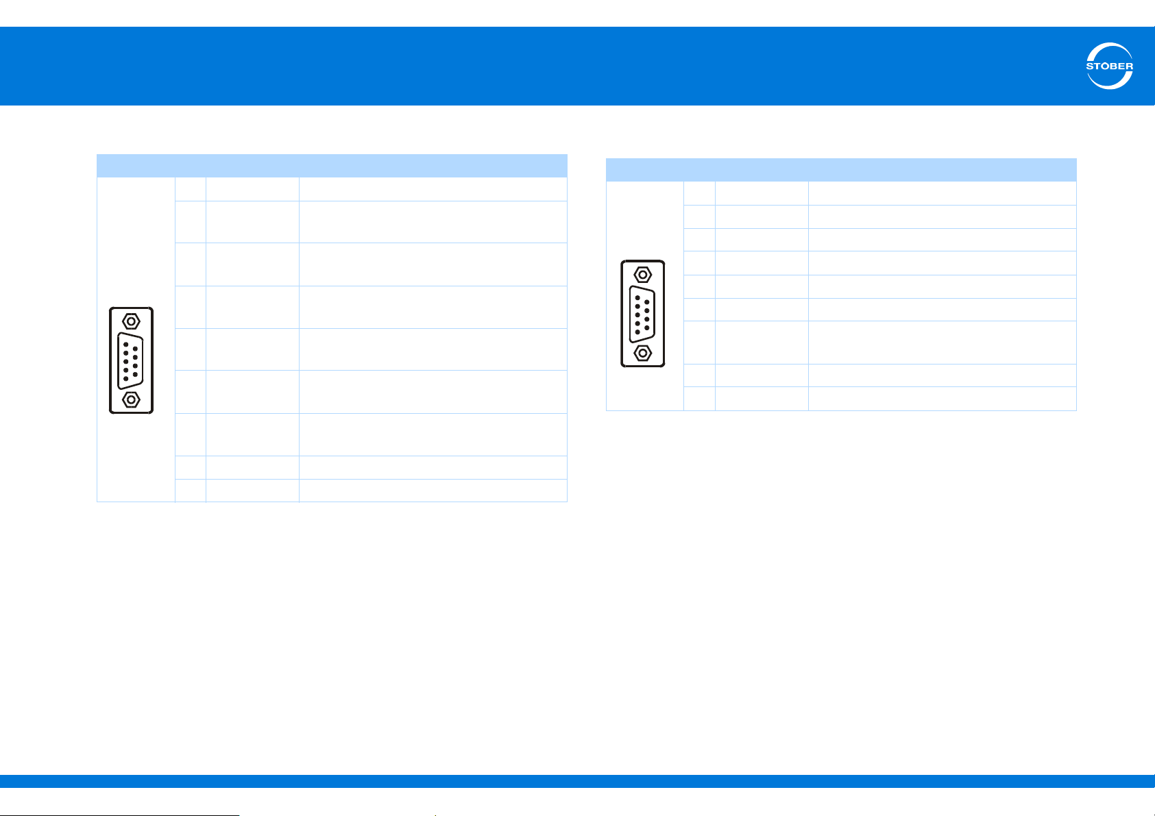
5
5
1
9
6
5
1
9
6
Connecting
Commissioning Instructions SD6
Terminal description of X120 for incremental signals
Pin Designation Function
1 GND-ENC Reference potential for pin 2 to pin 7
Connector
2 N+ Differential input/output for the
N channel
3 N- Inverse differential input/output for the N
channel
4 A- Inverse differential input/output for the A
channel
5 A+ Differential input/output for the
A channel
6 B+ Differential input/output for the
B channel
7 B- Inverse differential input/output for the B
channel
8U
2
Encoder supply
9 GND Reference for pin 8
Terminal description of X120 for stepper motor signals
Pin Designation Function
1 GND-ENC Reference potential for pin 2 to pin 7
Connector
2— —
3— —
4 Imp- Inverse differential input/output for pulses
5 Imp+ Differential input/output for pulses
6 Direction+ Differential input/output for the direction
7 Direction- Inverse differential input/output for the
direction
8U
2
Encoder supply
9 GND Reference for pin 8
ID 442537.01 57WE KEEP THINGS MOVING
Page 58
5
Connecting
Commissioning Instructions SD6
5.6.8 X140
Encoder connection X140 is an integral part of terminal module RI6.
Resolver specification (evaluation)
U
2
I
2
f
2
P
max
Transfer ratio 0.5 ± 5 %
Number of poles 2, 4 and 6
Phase shift ± 20 el.°
Maximum cable
length
EnDat 2.1 specification with and without sin-cos channels (evaluation)
U
2
I
2 max
I
2 min
Limit frequency 225 kHz
Encoder type Single and multiturn
-10 V ... +10 V
80 mA
7-9 kHz
0.8 W
100 m
5–12 V, see encoder supply
250 mA,
total of X4, X120 and X140 (EnDat): 500 mA
13 mA
Calculation example – limit frequency
... for encoder with 2,048 pulses per revolution:
3000 revolutions per minute (equivalent to 50 revolutions per
second) * 2048 pulses per revolution
= 102,400 pulses per second
= 102.4 kHz
Specification for EnDat 2.2
Encoder type Single and multiturn
Clock frequency 4 MHz
Encoder supply
U
2
5 V
(controlled at
cable end)
5 V
(controlled at
X4)
10 V
(unregulated)
Through
Encoder sense line connected to pin
12 (sense)
Pin 12 (sense) bridged with pin 4
(UB+)
STOBER servo
motors
EnDat 2.1/2.2
TTL
(for customerspecific solutions)
Pin 12 (sense) not
used
Maximum cable
length
ID 442537.01 58WE KEEP THINGS MOVING
100 m
Page 59
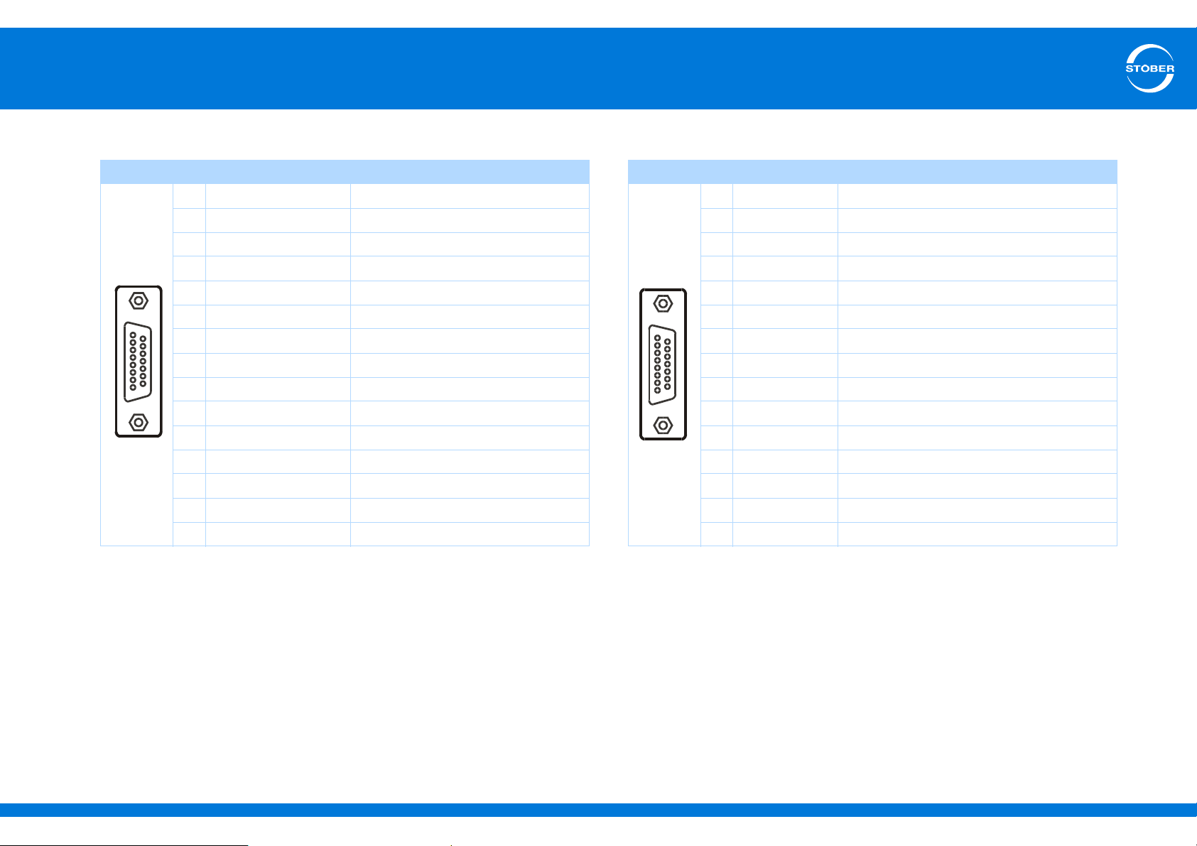
5
9
15
1
8
9
15
1
8
Connecting
Commissioning Instructions SD6
Terminal description X140 resolver Terminal description X140 EnDat sin/cos
a)
Pin
Socket
a) View of sub-D
Designation Function
1 Sin+ Sin input
2 R1 Ref- Resolver excitation signal
3 Cos+ Cos input
4— —
5— —
6 R2 Ref+ Resolver excitation signal
7— —
8— —
9 Sin- Sin input (inverse)
10 — —
11 Cos- Cos input (inverse)
12 — —
13 — —
14 — —
15 — —
a)
Pin
Socket
a) View of sub-D
Designation Function
1 Sin+ Sin input
2 GND Reference for encoder supply to pin 4
3 Cos+ Cos input
4U
2
Encoder supply
5 DATA+ Differential input for DATA
6— —
7— —
8 CLK+ Differential input for CLOCK
9 Sin- Inverse sin input
10 — —
11 Cos- Inverse cos input
12 Sense Sense signals for voltage control
13 DATA- Inverse differential input for DATA
14 — —
15 CLK- Inverse differential input for CLOCK
ID 442537.01 59WE KEEP THINGS MOVING
Page 60
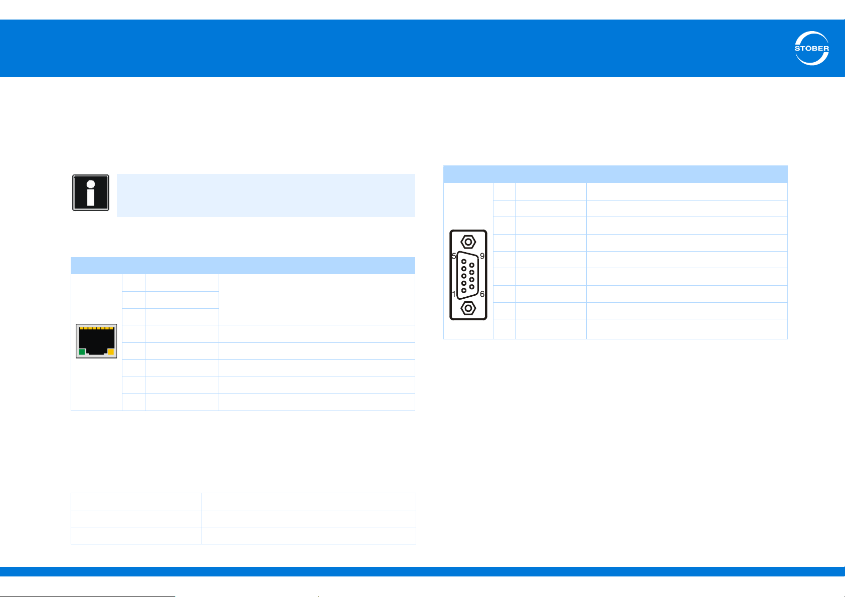
5
Connecting
Commissioning Instructions SD6
5.7 Communication modules
5.7.1 X200, X201: EtherCAT
Accessory part EC6 is required for an accessory part.
Information
For more extensive information about EtherCAT consult the
EtherCAT operating instructions (see section 1.2 Other manuals)!
X200 and X201 terminal description
Pin Designation Function
1 TxData+ EtherCAT communication
2 TxData3 RecvData+
4— —
5— —
6 RecvData- EtherCAT communication
7— —
8— —
Cable specification
STOBER provides ready-made cables for the EtherCAT connection.
These cables must be used to ensure proper functionality.
It is also possible to use cables with the following specification:
5.7.2 X200: CANopen
Accessory part EC6 is required for a CANopen connection.
Terminal description X200
Pin Designation Function
Connec-
tor
Cable specification
To ensure error-free operation, especially at high baud rates, we
recommend a shielded fieldbus cable that meets all necessary technical
requirements (for example a ripple resistor or sufficiently low cable
capacitance – about 60 nF/km) for CANopen communication (in
accordance with ISO 11898).
1— —
2 CAN-Low CAN-Low lead
3 GND Reference ground
4— —
5— —
6— —
7 CAN-High CAN-High lead
8— —
9— —
Plug wiring Patch or crossover
Quality CAT5e
Shielding SFTP or PIMF
ID 442537.01 60WE KEEP THINGS MOVING
Page 61
5
Connecting
Commissioning Instructions SD6
5.8 Drive controller wiring
WARNING!
Danger of personal injury and material damage due to electric
shock!
Always switch off all power supply voltage before working on the
drive controller! Note that the discharge time of the DC link
capacitors is 5 minutes. You can only determine the absence of
voltage after this time period.
Requirements
• You have a system contact plan describing the connection of the
drive controller.
You need
• a tool to mount the accessory and tighten the fastening screws.
Bottom of the device
1. Disconnect all the terminals on the bottom of the drive controller.
2. Attach the EMC shroud (see
3. Optional:
Connect a braking resistor and the DL6 module for Quick DC-Link
to terminal X30 and attach the terminal.
4. To connect the motor temperature sensor, control of the motor
holding brake and the motor itself with the drive controller, wire the
conductors of the power cable with terminals X2, X5 and X20.
5. Attach the power cable to the EMC shroud.
6. Attach terminal X20.
4.7 EMC shroud).
7. Connect the power supply voltage for the holding brake to terminal
X6 and attach it.
8. Attach terminals X2 and X5.
9. Optional:
Connect an encoder to terminal X4.
10. Wire the enable signal and relay 1 to terminal X1 and attach them.
Top of the device
11. Connect the protective ground (see section
12. Connect the power supply to terminal X10.
13. Connect the 24 vdc power supply for the control electronics to
terminal X11.
14. If you do not need any safety technology, connect 24 V to terminal
X12.
If you need the STO safety function, proceed as described in the
ST6 manual.
15. Optional:
To use IGB motion bus functionality, connect additional drive
controllers, PCs or Internet connections to an IGB network via
sockets X3A and X3B.
16. Optional:
Connect EtherCAT or CANopen fieldbuses to sockets X200 and
X201 via EC6 or CA6 modules.
The drive controller is connected. Use an appropriate function test
to check to ensure the wiring and functionality of the individual
components are correct.
5.4.3 Housing ground).
ID 442537.01 61WE KEEP THINGS MOVING
Page 62
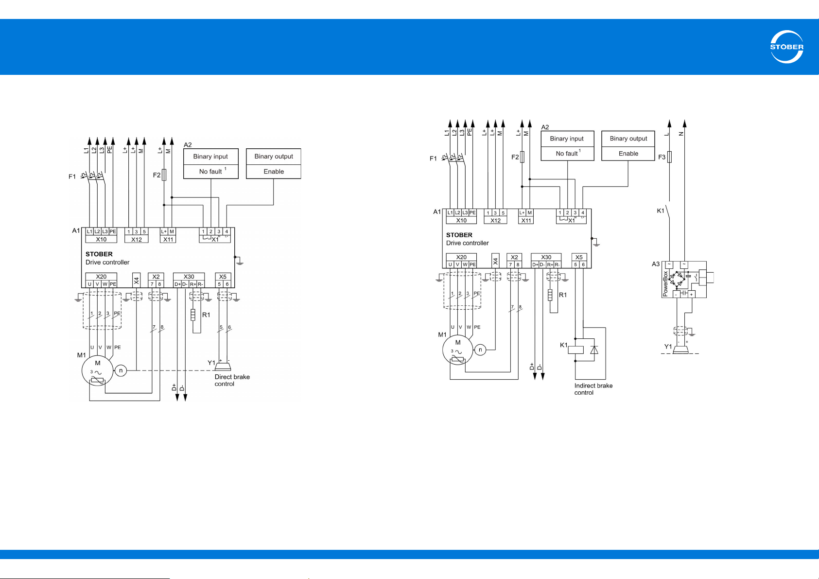
5
Connecting
Commissioning Instructions SD6
5.8.1 Examples of connections
The graphic below shows wiring connection examples with direct brake
control.
The graphic below shows wiring connection examples with indirect
brake control.
Legend
A1 Drive controller M1 Motor
A2 Control system n Speed
F Fuse R Resistance
L1 – L3 Three-phase supply Y Brake
L+ 24 vdc power supply
M Reference ground
ID 442537.01 62WE KEEP THINGS MOVING
1
Signal (variable)
Legend
A1 Drive controller M Reference ground
A2 Control system M1 Motor
A3 Brake rectifier n Speed
F Fuse N Neutral conductor
K Contactor R Resistance
L 230 vdc power supply Y Brake
L1 – L3 Three-phase supply
L+ 24 vdc power supply
1
Signal (variable)
Page 63
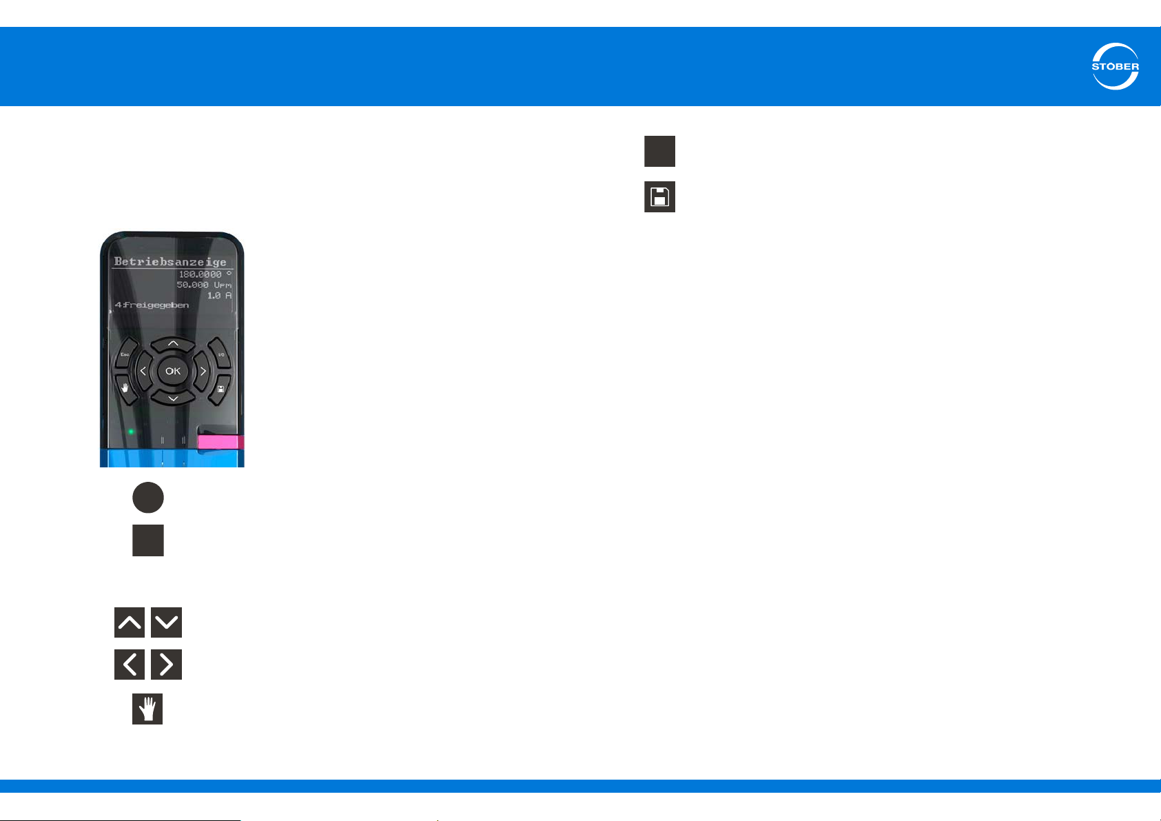
6
OK
Esc
I/0
Commissioning
Commissioning Instructions SD6
6 Commissioning
6.1 Drive controller – control unit
The control unit consists of a graphical display (LCD) and sensor keys.
• Select the level, parameter groups and parameters.
• Accept modified parameter values.
• Display parameters of the start display.
• Navigate one level back.
• Reject modified parameter values.
• Acknowledge fault.
• Enable drive in local mode if parameterized.
• To save data with protection against power failure: Press
the key and hold it for 3 seconds.
• Select parameter within a parameter group.
• Change parameter values.
• Select parameter group.
• Select character position of a parameter.
• Activate/deactivate local mode (deactivation causes the
enable to be deleted).
ID 442537.01 63WE KEEP THINGS MOVING
Page 64
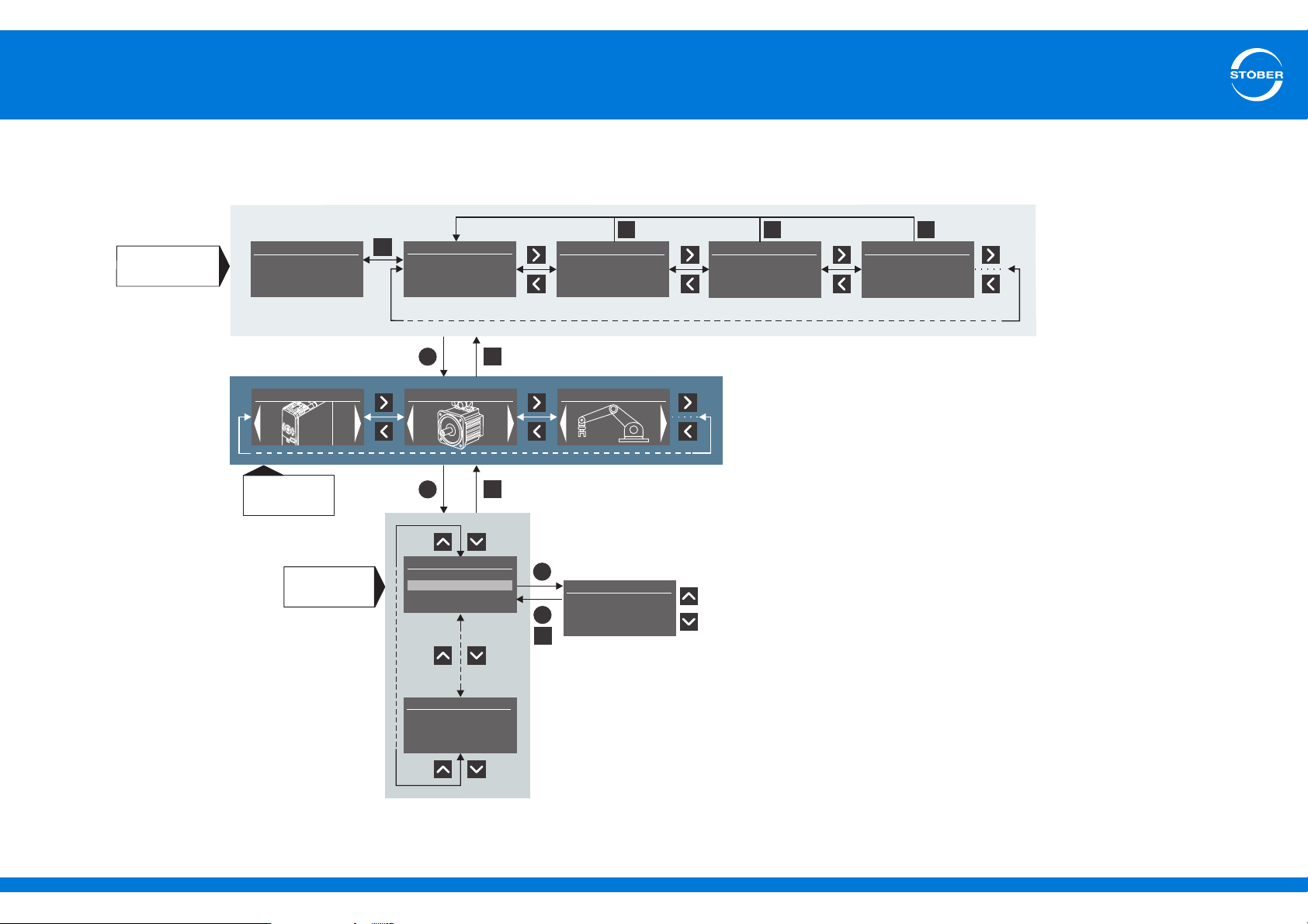
6
OK
Esc
Parameter
groups
A:Drive controller
OK
C:Machine
B:Motor
Esc
B:Motor
B41 Autotuning
B40 Phase test
B24 Switching freq.
Esc
Esc
OK
OK
B26 Motor encoder
2:X4-encoder
Change parameter value
B26 Motor encoder
B:Motor
B04 El. nameplate
B02BackEMF
B00 Motor type
B310 Brake management
Parameters
Quick access
to parameters
Status display
123.567°
0.000 Upm
0.0 A
3:SwitchOnDis.
0.0 A
0.0 A
Status display 1
E49 Inhibit reason
01000011
E47 Inhibit reason
1:Enable
0.0 A
Status display 2
E19 Binary inputs
0000000000000000
E27 Binary outputs
0000000000000001
Esc
Status display
I80 Current position
E08 N-motor filtered
E00 I-Motor
E80 Oper. Cond.
START DISPLAY
Esc
Esc
Esc
0.0 A
Status display 3
E52 DriveCtrlrInfo
[0] SD6A06
[1] 999
[2] 7000043
Commissioning
Commissioning Instructions SD6
6.1.1 Menu structure and navigation
ID 442537.01 64WE KEEP THINGS MOVING
Page 65
6
Commissioning
Commissioning Instructions SD6
Parameters – quick access
Quick access gives you direct access to the status of the most important
(diagnostic) parameters. This level consists of a start display and four
overviews of specific content:
Status display 1
switch on disable; status display 2
analog and binary inputs and outputs; status display 3
controller data including type, firmware, integrated option modules, etc.
You can navigate within this level with the right and left arrow keys.
Press "ESC" to reach the parameters associated with the values that
appear in the start display. These parameters are individually
configurable.
Parameter groups
Parameters are combined together in groups based on their functional
properties, for example "Drive controller," "Motor," "Machine,"
"Terminals", etc.You can navigate within this level with the right and left
arrow keys; Select one of the possible groups with "OK.
Parameters
You can navigate in a parameter group with the upper and lower arrow
keys. Select one of the possible parameters with "OK." To change a
parameter value, choose the corresponding character position with the
right and left arrow keys, then select the new value with the upper and
lower arrow keys. Accept changes with "OK" or reject them with "Esc.
provides information about the causes of a possible
provides information about the
for general drive
6.2 Wiring and function test
You have connected the SD6 drive controller together with accessory
and you would like to check whether the wiring is correct and test the
functionality of the components as a group.
You can perform an initial function test with STOBER standard
parameterization if you are operating the drive controller together with a
STOBER synchronous servo motor and an EnDat encoder.
In this case the electronic nameplate of the motor is read when the
device starts and the corresponding data is transferred to the drive
controller.
6.2.1 Schematic test sequence
The diagram below shows the schematic sequence of the wiring and
function test. A detailed description follows.
Information
Note that a modified parameter value can only be saved so it will be
retained through a power failure with the save key on the control
unit.
ID 442537.01 65WE KEEP THINGS MOVING
Page 66
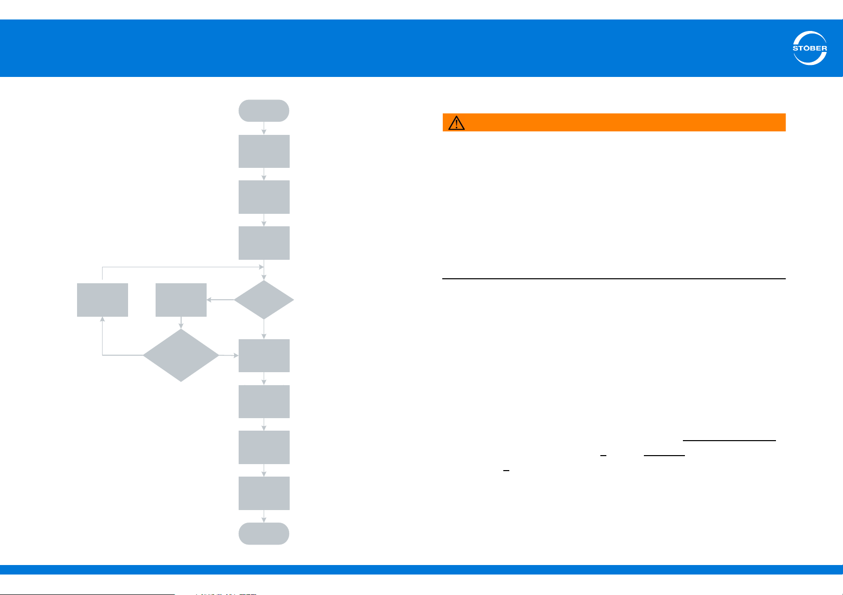
6
Switch on disable?
(E48)
Turn on 24 vdc
brake power suppy
Turn on 24 vdc drive
controller power
suppy
Turn on mains
power suppy
Beginning of test
Determine cause
(E47, E49)
Rectify cause
Yes
No
Single cause:
Application enable missing?
(E47, E49.x)
No
Activate local
operation
Yes
Ready to
switch on
Enable drive
controller
Move motor
End of test
Commissioning
Commissioning Instructions SD6
6.2.2 Practical test sequence
WARNING!
Danger due to moving parts!
The motor shaft is turning in the wiring and function test described
below!
Clear the danger zone before the test.
Do not connect any mechanical systems to the motor or gear unit
until the function test is completed.
Make certain the components fastened to the motor, such as feather
keys or coupling elements, are sufficiently secured against
centrifugal forces.
Perform each step in the specified order.
Test preparations
1. Switch on the 24 vdc power supply of the brake.
2. Switch on the 24 vdc power supply of the drive controller.
3. Switch on the power supply.
4. Deactivate the STO safety function by connecting 24 V to terminal
X12.
ID 442537.01 66WE KEEP THINGS MOVING
The drive controller switches either to the Ready to switch on
state (continue with step 5
step 6
).
) or the disabled state (continue with
Page 67
6
Commissioning
Commissioning Instructions SD6
Performing the test
5. The drive controller is ready to switch on
5.1 Activate local mode with the manual button.
5.2 Enable the drive controller with the I/O key.
5.3 Turn the motor axis with the right and left arrow keys at the
velocity and acceleration configured in parameter I12.
You have wired all components correctly. The function test
was completed successfully.
6. Drive controller is disabled
(Display = 3: switchOnDis, parameter E48).
6.1 Determine the causes for the switch on disable and rectify them:
Parameter E49 contains a coded version of the possible causes
and parameter E47 shows them in plain text.
6.2 Next proceed as described in step 5.
Note:
If the missing enable for the CBM application is the only cause
for the switch on disable, switch directly to local mode and
continue with the test as described in step 5.
Finishing the test
7. Disable the drive controller with the I/O key.
8. Switch to normal mode with the manual key.
6.3 Additional parameter information
You can use to parameters to
• adjust the functionality of the drive controller to your application,
• display current values such as actual speed or actual torque and
• trigger actions such as "Save values" or "autotuning."
Parameter group I controls all movements, while group E is used for
device and application display.
You can use parameter I10 to control the maximum velocity of the motor
axis. E47 and E49 provide information about the device state of the
drive controller as well as possible causes for a switch on disable.
E 47: Cause for the "Switch on disable" state
This parameter contains the causes for the "Switch on disable" state in
plain text. Multiple causes appear in the display successively for 1.5
seconds each.
0 Inactive
1 Enable
2 Network/DC link
3Axis
4 IGB motion bus
5 STO active
6 Quick stop
7 Control word
ID 442537.01 67WE KEEP THINGS MOVING
Page 68
6
Commissioning
Commissioning Instructions SD6
E 49 – "Switch on disable" state
This parameter contains the causes for the "Switch on disable" state in
coded format (each bit encodes one cause).
0 Enable The following rules apply, depending on the relevant
device state machine:
• CiA 402:
X1 enable is inactive ("Low");
X1 enable must always be active.
• Standard device state machine:
A34 auto-start is inactive and X1.Enable is active.
X1 Enable must be Low
(protection against automatic restart).
1Network/DC
link
2 Axis • No axis is active or
3 Motion bus The IGB motion bus is projected, but:
4 STO The STO safety function is active (Safe Torque Off).
• There is no/not sufficient network voltage
• A38 DC power-input is not active.
• axis switchover is running.
• A124 IGB exception state is not activated or
• A155 IGB-state is not equal to 3 or
• The IGB motion bus is not synchronized (see A182
IGB motion bus conditions)
I10 – Maximum velocity
Maximum velocity as a limit for
• CiA 402 Homing mode: A587
• CiA 402 Jog: I12
Information
The limit is set without event 54:following error occurring.
5 Quick stop CiA 402 only:
The quick stop signal to block 191 must be "Low" and no
quick stop command is permitted via A515 Controlword
6 Control word CiA 402 only:
The value of A515 Controlword is not "Stop".
7 Reserved —
ID 442537.01 68WE KEEP THINGS MOVING
Page 69

Global presence
STOBER subsidiaries
Technical offices
for advice and marketing in Germany
Global presence
for advice and marketing in about 25
countries
Service network
Germany
Service network
international
Austria
STÖBER ANTRIEBSTECHNIK
GmbH
Hauptstraße 41a
4663 Laakirchen
Fon +43 7613 7600-0
Fax +43 7613 7600-2525
E-Mail: [email protected]
www.stoeber.at
Switzerland
STÖBER SCHWEIZ AG
Rugghölzli 2
5453 Remetschwil
Fon +41 56 496 96 50
Fax +41 56 496 96 55
E-Mail: [email protected]
www.stoeber.ch
Great Britain
STOBER DRIVES Ltd.
Centrix House
Upper Keys Business Village
Keys Park Road
Hednesford, Cannock
STAFFORDSHIRE WS12 2HA
Fon +44 1543 458 858
Fax +44 1543 448 688
E-Mail: [email protected]
www.stober.co.uk
France
STÖBER S.a.r.l.
131, Chemin du Bac à Traille
Les Portes du Rhône
69300 Caluire et Cuire
Fon +33 4 78989180
Fax +33 4 78985901
E-Mail: [email protected]
www.stober.fr
USA
STOBER DRIVES INC.
1781 Downing Drive
Maysville, KY 41056
Fon +1 606 7595090
Fax +1 606 7595045
E-Mail: [email protected]
www.stober.com
China
STOBER CHINA
German Centre Beijing
Unit 2010, Landmark Tower 2,
8 North Dongsanhuan Road
Chaoyang District
100004 Beijing
Fon +86 10 65907391
Fax +86 10 65907393
E-Mail: [email protected]
www.stoeber.cn
Singapore
STOBER Singapore
50 Tagore Lane
#05-06B Entrepreneur Centre
Singapore 787494
Fon +65 65112912
Fax +65 65112969
E-Mail: [email protected]
www.stober.sg
Italy
STÖBER TRASMISSIONI S. r. l.
Via Italo Calvino, 7 Palazzina D
20017 Rho (MI)
Fon +39 02 93909-570
Fax +39 02 93909-325
E-Mail: [email protected]
www.stoeber.it
Japan
STOBER Japan
P.O. Box 113-002, 6 chome
15-8, Hon-komagome
Bunkyo-ku
Tokyo
Fon +81 3 5395-6788
Fax +81 3 5395-6799
E-Mail: [email protected]
www.stober.co.jp
ID 442537.01 WE KEEP THINGS MOVING 69
Page 70
STÖBER ANTRIEBSTECHNIK GmbH & Co. KG
Technische Änderungen vorbehalten
Errors and changes excepted
ID 442537.01
01/2015
442537.01
Kieselbronner Str. 12
75177 PFORZHEIM
GERMANY
Tel. +49 7231 582-0
Fax +49 7231 582-1000
E-Mail: [email protected]
www.stober.com
24h Service Hotline +49 180 5 786 323
 Loading...