

Page 1

CAN 5000 and DP 5000
Commissioning Instructions
Installation
Connecting
V 5.6-E or later
04/2012 en
Page 2

Table of contents
Commissioning Instructions CAN 5000 and DP 5000
Table of contents
1 Overview . . . . . . . . . . . . . . . . . . . . . . . . . . . . . . .
2 Notes on Safety. . . . . . . . . . . . . . . . . . . . . . . . . .
2.1 Component part of the product . . . . . . . . . . . . . . . . . . . . . . . . 4
2.2 Operation in accordance with its intended use. . . . . . . . . . . . 4
2.3 Qualified personnel. . . . . . . . . . . . . . . . . . . . . . . . . . . . . . . . . 4
2.4 Installation and connection . . . . . . . . . . . . . . . . . . . . . . . . . . . 5
2.5 Commissioning, operation and service. . . . . . . . . . . . . . . . . . 6
2.6 Disposal . . . . . . . . . . . . . . . . . . . . . . . . . . . . . . . . . . . . . . . . . 6
2.7 Presentation of notes on safety. . . . . . . . . . . . . . . . . . . . . . . . 7
3 Installation. . . . . . . . . . . . . . . . . . . . . . . . . . . . . .
3.1 Installation in the MDS 5000 and SDS 5000. . . . . . . . . . . . . . 8
3.2 Installation in the FDS 5000 . . . . . . . . . . . . . . . . . . . . . . . . . . 10
4 Connection . . . . . . . . . . . . . . . . . . . . . . . . . . . . .
4.1 CAN 5000 . . . . . . . . . . . . . . . . . . . . . . . . . . . . . . . . . . . . . . . . 13
3
4
8
13
4.2 DP 5000 . . . . . . . . . . . . . . . . . . . . . . . . . . . . . . . . . . . . . . . . . 14
WE KEEP THINGS MOVING
ID 442148.032
Page 3
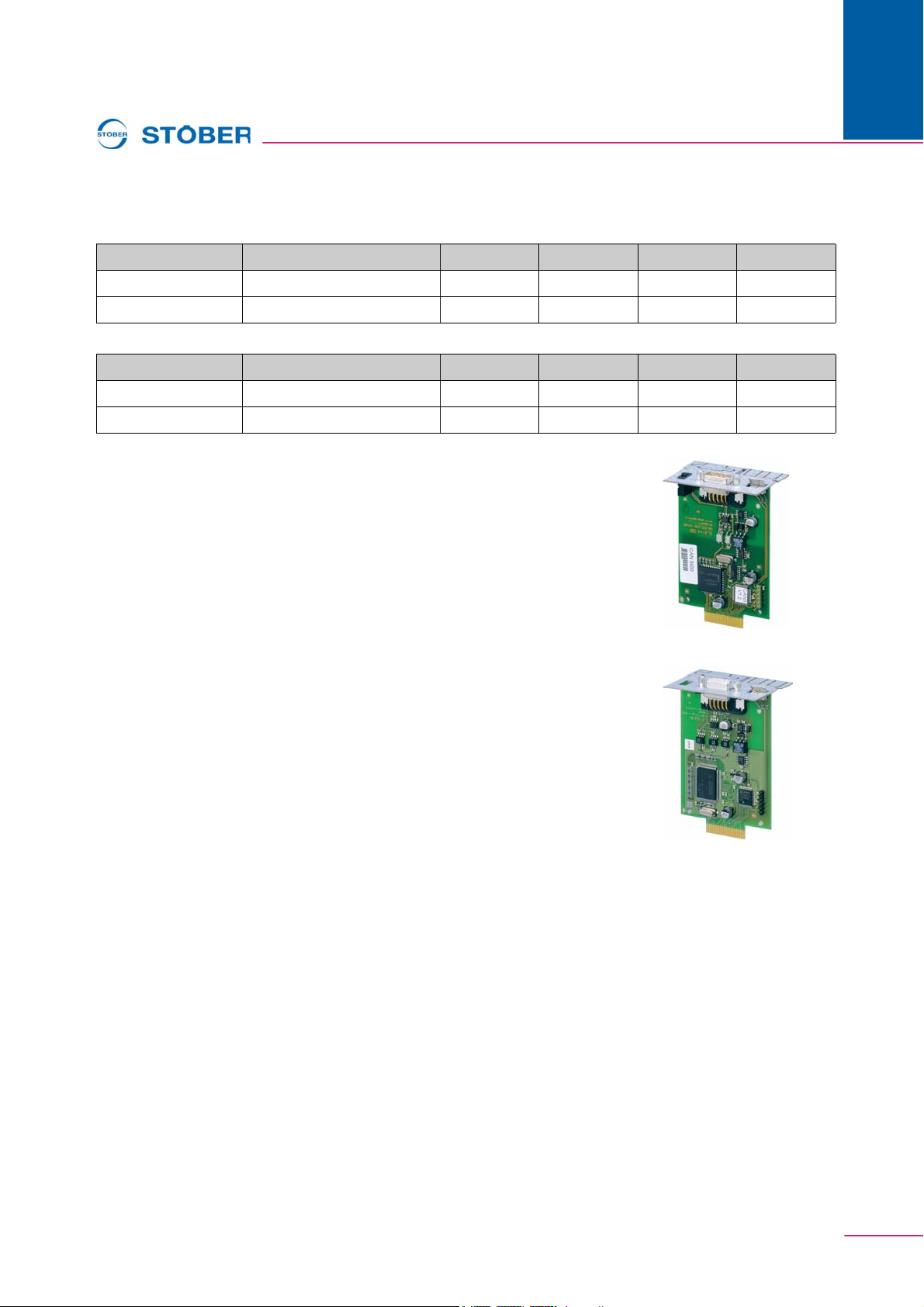
Overview
Commissioning Instructions CAN 5000 and DP 5000
1Overview
Inverter HW status of the inverter CAN 5000 DP 5000 ECS 5000 PN 5000
FDS 5000A 200 or higher Yes Yes Yes Yes
FDS 5000 up to 199 Yes Yes Yes No
Inverter HW status of the inverter CAN 5000 DP 5000 ECS 5000 PN 5000
MDS 5000A 200 or higher Yes Yes Yes Yes
MDS 5000 up to 199 Yes Yes Yes No
Fieldbus module CANopen® DS-301 CAN 5000
ID No. 44574
1
Description: Accessory part for coupling of CAN-Bus
Fieldbus module PROFIBUS DP-V1 DP 5000
ID No. 44575
Description: Accessory part for coupling of PROFIBUS DP-V1
WE KEEP THINGS MOVING
3ID 442148.03
Page 4
2
Notes on Safety
Commissioning Instructions CAN 5000 and DP 5000
2 Notes on Safety
The devices may cause risks. For these reasons, comply with the following:
• The safety notes listed in the following sections and points
• The technical rules and regulations.
In addition, always read the appropriate documentation. STÖBER ANTRIEBSTECHNIK GmbH + Co. KG
accepts no liability for damages caused by non-adherence to the instructions or applicable regulations.
Subject to technical changes to improve the devices without prior notice. This documentation is purely a
product description. It does not represent promised properties in the sense of warranty law.
2.1 Component part of the product
The technical documentation is a component part of a product.
• Since the technical documentation contains important inform ation, always ke ep it handy in the vicinity of
the device until the machine is disposed of.
• If the product is sold, disposed of, or rented out, always include the technical documentation with the
product.
2.2 Operation in accordance with its intended use
The CAN 5000 accessory is only intended for establishing communication between devices from the 5th
generation of STÖBER inverters and a CANopen® network.
Improper use includes integration in other communication networks.
The DP5000 accessory is only intended for establishing communication between devices from the 5th
generation of STÖBER inverters and a PROFIBUS network.
Improper use includes integration in other communication networks.
2.3 Qualified personnel
Since the devices may harbor residual risks, all configuration, transport ation, installation and commissioning
tasks including operation and disposal may only be performed by trained personnel who are aware of the
possible risks.
Personnel must have the qualifications required for the job. The fol lowing table lists examples of occupational
qualifications for the jobs:
Activity Possible occupational qualifications
Transportation and storage Worker skilled in storage logistics or comparable
training
Configuration - Graduate engineer (electro-technology or
electrical power technology)
- Technician (m/f) (electro-technology)
WE KEEP THINGS MOVING
ID 442148.034
Page 5
Commissioning Instructions CAN 5000 and DP 5000
Activity Possible occupational qualifications
Installation and connection Electronics technician (m/f)
2
Notes on Safety
Commissioning
(of a standard application)
Programming Graduate engineer (electro-technology or
Operation - Technician (m/f) (electro-technology)
Disposal Electronics technician (m/f)
Tab. 2-1: examples of occupational qualifications
In addition, the valid regulations, the legal requirements, the reference books, this technical documentation
and, in particular, the safety information contained therein must be carefully
•read
• understood and
• complied with
- Technician (m/f) (electro-technology)
- Master electro technician (m/f)
electrical power technology)
- Master electro technician (m/f)
2.4 Installation and connection
Installation and connection work are only permitted after the device has been isolated from the power!
The accessory installation instructions allow the following actions during the installation of accessories:
• The housing in the upper slot can be opened
• The housing in the bottom slot can be opened.
Opening the housing in another place or for other purposes is not permitted.
The accessory installation instructions allow the following actions during the installation of accessories:
• The housing in the upper slot can be opened.
Opening the housing in another place or for other purposes is not permitted.
Use only copper lines. For the line cross sections to be used, refer to DIN VDE 0298-4 or DIN EN 60204-1
Appendix D and Appendix G.
Protect the device from falling parts (pieces of wire, leads, metal parts, and so on) during installation or other
tasks in the switching cabinet. Parts with conductive proper ties inside the inverter can ca use short circuit s or
device failure.
The motor must have an integrated temperature monitor with basic isolation in acc. with EN 61800- 5-1 or
external motor overload protection must be used.
The permissible protection class is protective ground. Operation is not permitted unless the protective
conductor is connected in accordance with the regulations.
Comply with the applicable instructions for installation and commissioning of motor and brakes.
WE KEEP THINGS MOVING
5ID 442148.03
Page 6
2
Notes on Safety
Commissioning Instructions CAN 5000 and DP 5000
2.5 Commissioning, operation and service
Remove additional coverings before commissioning so that the device cannot overheat. During installation,
provide the free spaces specified in the projecting manuals to prevent the inverter from overheating.
The housing of the drive controller must be closed before you turn on the supply voltage. When the supply
voltage is on, dangerous voltages can be present on the connection terminals and the cables and motor
terminals connected to them. Remember that the device is not necessarily de-energized after all indicators
have gone off.
When network voltage is applied, the following are prohibited:
• Opening the housing
• Connecting or disconnecting the connection terminals
• Installing accessories
Before carrying out any work on the machine, observe all the following five safety regulations in the abovementioned sequence:
1. Enable. Ensure that you also activate the auxiliary circuits.
2. Secure against switching on.
3. Ensure that the parts are de-energized.
4. Earth and short-circuit.
5. Cover or isolate any live neighboring parts.
Information
Please note that the discharge time for the intermediate circuit capacitors is
5 min. You can only ensure that the parts are de-energized after this time.
You can then start your work on the drive controller. Repairs may only be performed by STÖBER
ANTRIEBSTECHNIK GmbH + Co. KG.
Send defective devices together with a fault description to:
STÖBER ANTRIEBSTECHNIK GmbH + Co. KG
Department VS-EL
Kieselbronner Str.12
75177 Pforzheim
GERMANY
2.6 Disposal
Please comply with the latest national and regional regulations! Dispose of the individual parts separately
depending on their nature and currently valid regulations such as, for example:
• Electronic scrap (PCBs)
• Plastic
• Sheet metal
• Copper
•Aluminum
WE KEEP THINGS MOVING
ID 442148.036
Page 7
Commissioning Instructions CAN 5000 and DP 5000
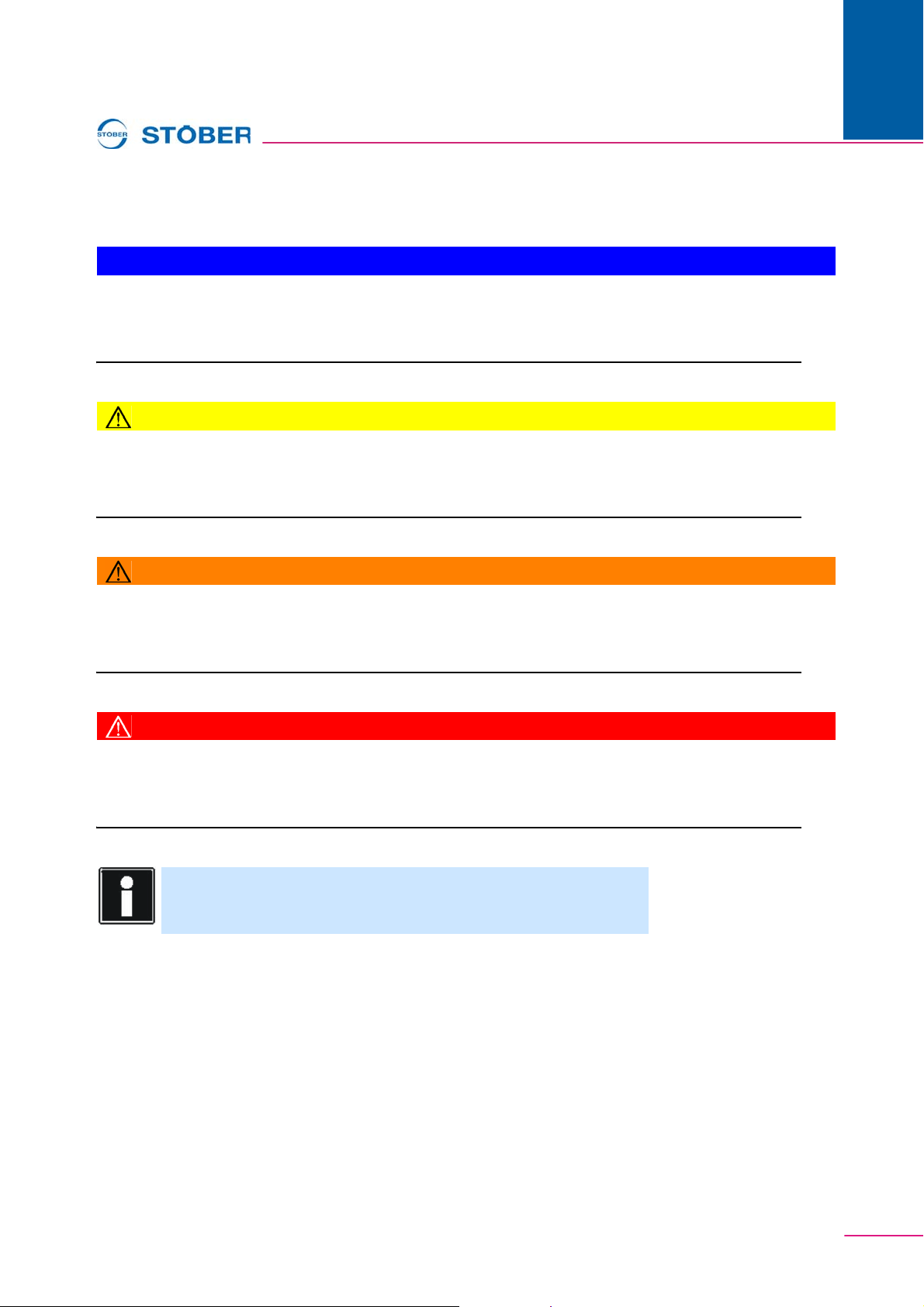
2.7 Presentation of notes on safety
NOTICE
Notice
means that property damage may occur
X if the stated precautionary measures are not taken.
CAUTION!
Caution
with warning triangle means that minor injury may occur
X if the stated precautionary measures are not taken.
2
Notes on Safety
WARNING!
Warning
means that there may be a serious danger of death
X if the stated precautionary measures are not taken.
DANGER!
Danger
means that serious danger of death exists
X if the stated precautionary measures are not taken.
Information
indicates important information about the product or a highlighted
portion of the documentation which requires special attention.
WE KEEP THINGS MOVING
7ID 442148.03
Page 8
3
Installation
Commissioning Instructions CAN 5000 and DP 5000
3 Installation
3.1 Installation in the MDS 5000 and SDS 5000
Y o u will need the following accessories for the connection of CANopen® or PROFIBUS. The accessory part
is installed above the inverter's display.
• CANopen®: CAN 5000
• PROFIBUS: DP 5000
You will need the following for installation of CAN 5000 or DP 5000.
• A TX10 Torx screwdriver
• A pair of pliers
• Hexagon socket wrench, 4.5 mm
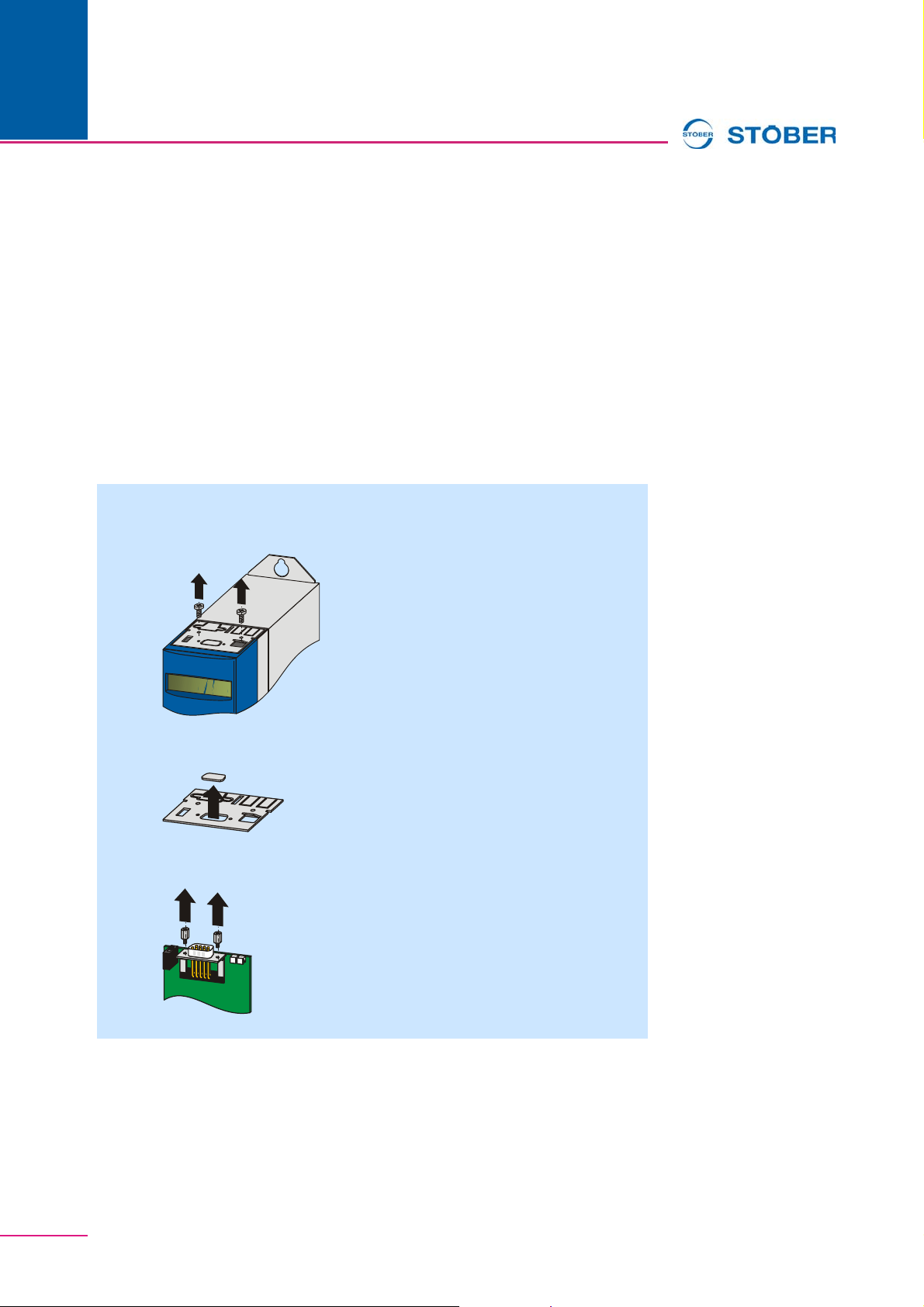
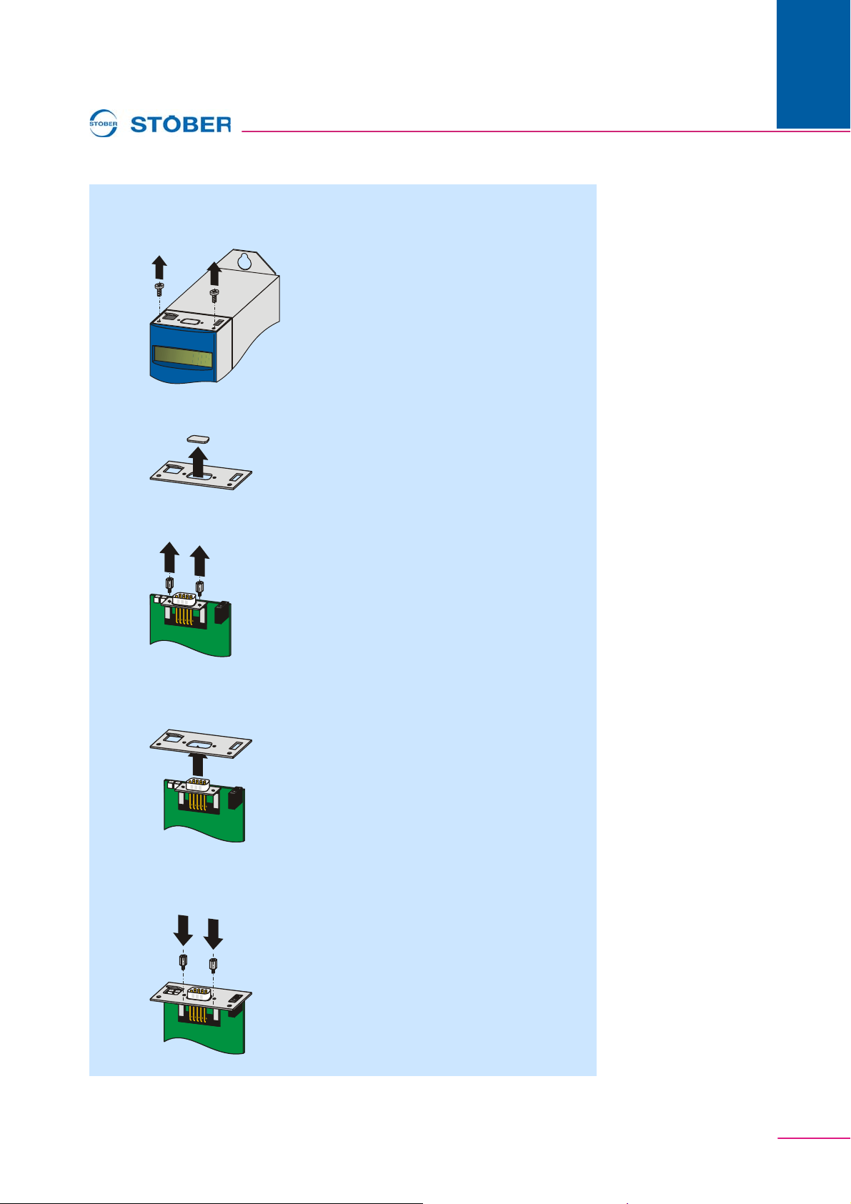
Installation of a CAN 5000 or DP 5000 in an inverter
1 Remove the mounting screws and take off the cover plate:
2 Remove the metal plate punch-out with a p air of pliers:
3 Remove the screws from the option board:
WE KEEP THINGS MOVING
ID 442148.038
Page 9
Commissioning Instructions CAN 5000 and DP 5000
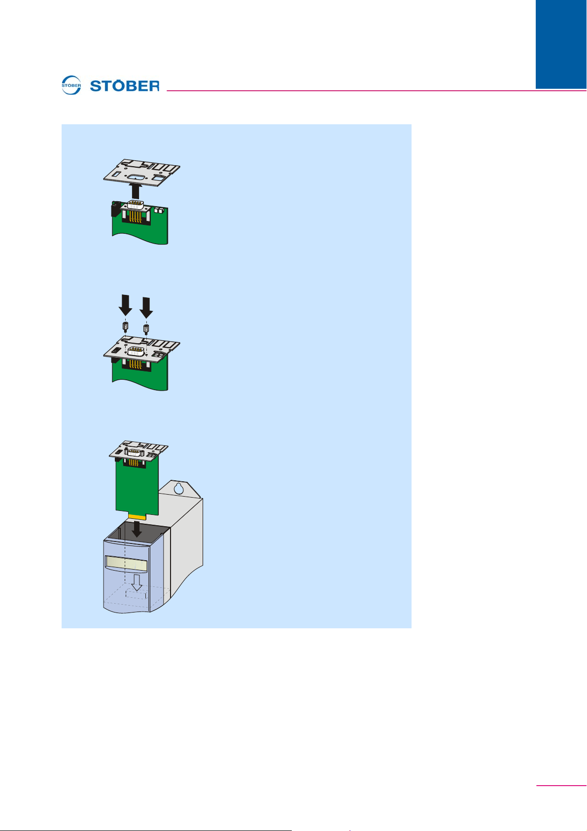
4 From below, thread the sub D plug connector of the PCB through the metal
plate:
5 Secure the PCB to the metal plate with the screws which you removed in
step 3:
3
Installation
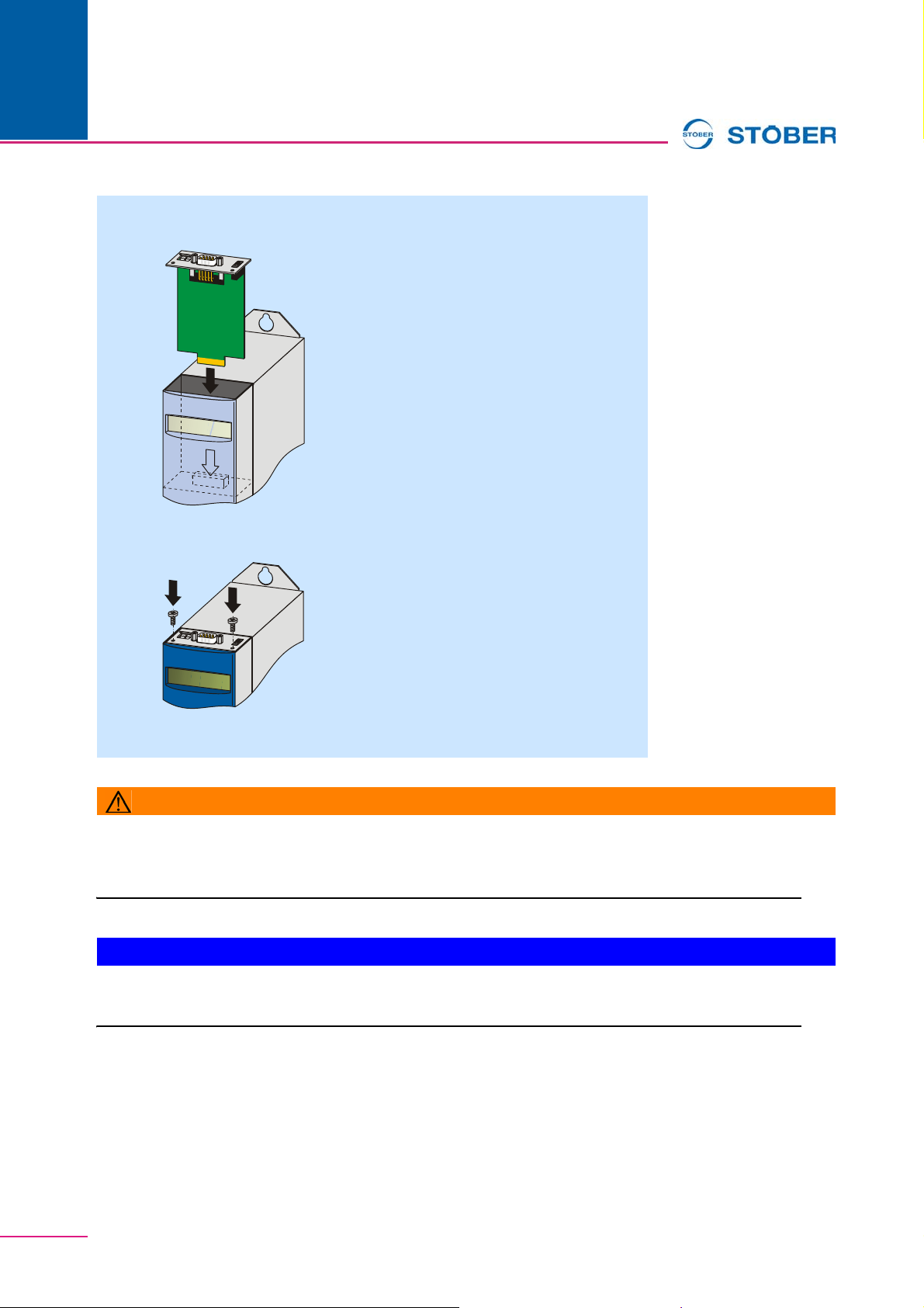
6 Guide the option board into the inverter so that the gold contacts slide into
the black connector:
WE KEEP THINGS MOVING
9ID 442148.03
Page 10
3
Installation
Commissioning Instructions CAN 5000 and DP 5000
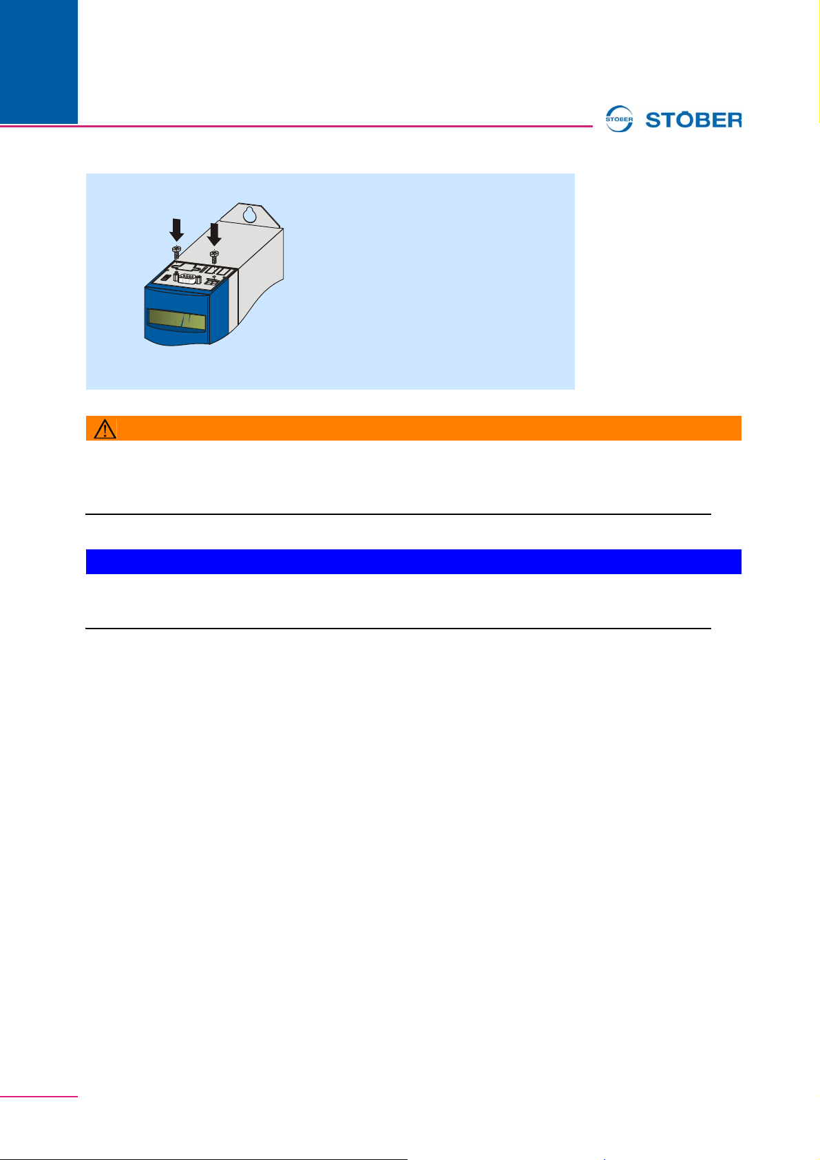
7 Secure the metal plate to the inverter with the mounting screws:
Ö You have now installed the accessory.
WARNING!
Danger of injury/death and property damage due to electric shock!
X Be fore inst alling accessories, turn off all vo ltag e supplies! Then wait 5 minutes for the DC link capacitors
to discharge. Never begin with accessory installation until after this!
NOTICE
Danger of property damage from incorrect installation of the devices!
X It is essential to comply with the following installation instructions to avoid damage to the devices.
3.2 Installation in the FDS 5000
Y o u will need the following accessories for the connection of CANopen® or PROFIBUS. The accessory part
is installed above the inverter's display.
• CANopen®: CAN 5000
• PROFIBUS: DP 5000
You will need the following for installation of CAN 5000 or DP 5000.
• A TX10 Torx screwdriver
• A pair of pliers
• Hexagon socket wrench, 4.5 mm
WE KEEP THINGS MOVING
ID 442148.0310
Page 11
Commissioning Instructions CAN 5000 and DP 5000
Installation of a CAN 5000 or DP 5000 in an inverter
1 Remove the mounting screws and take off the cover plate:
2 Remove the metal plate punch-ou t with a pair of pliers:
3
Installation
3 Remove the screws from the option board:
4 From below, thread the sub D plug connector of the PCB through the metal
plate:
5 Secure the PCB to the metal plate with the screws which you removed in
step 3:
WE KEEP THINGS MOVING
11ID 442148.03
Page 12
3
Installation
Commissioning Instructions CAN 5000 and DP 5000
6 Guide the option board into the inver ter so that the gold contacts slide into
the black connector:
7 Secure the metal plate to the inverter with the mounting screws:
Ö You have now installed the accessory.
WARNING!
Danger of injury/death and property damage due to electric shock!
X Before installing accessories, turn off all voltag e supplies! Then wait 5 minutes for the DC link capacitors
to discharge. Never begin with accessory installation until after this!
NOTICE
Danger of property damage from incorrect installation of the devices!
X It is essential to comply with the following installation instructions to avoid damage to the devices.
WE KEEP THINGS MOVING
ID 442148.0312
Page 13
Commissioning Instructions CAN 5000 and DP 5000
5
1
9
6
off
on
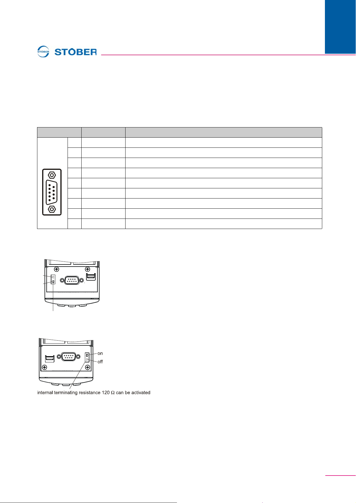
Internal terminating resistance 120 can be activated
Ω
4 Connection
4.1 CAN 5000
Terminal description X200
Pin Designation Function
1nc —
plug
2 CAN-low CAN-low line
3 GND Signal Ground
4nc —
5nc —
6 CAN-low CAN-low line connected internally with pin 2
4
Connection
7 CAN-high CAN-high line
8nc —
9 CAN-high CAN-high line connected internally with pin 7
MDS 5000, SDS 5000
FDS 5000
WE KEEP THINGS MOVING
13ID 442148.03
Page 14
4
Connection
Commissioning Instructions CAN 5000 and DP 5000
4.2 DP 5000
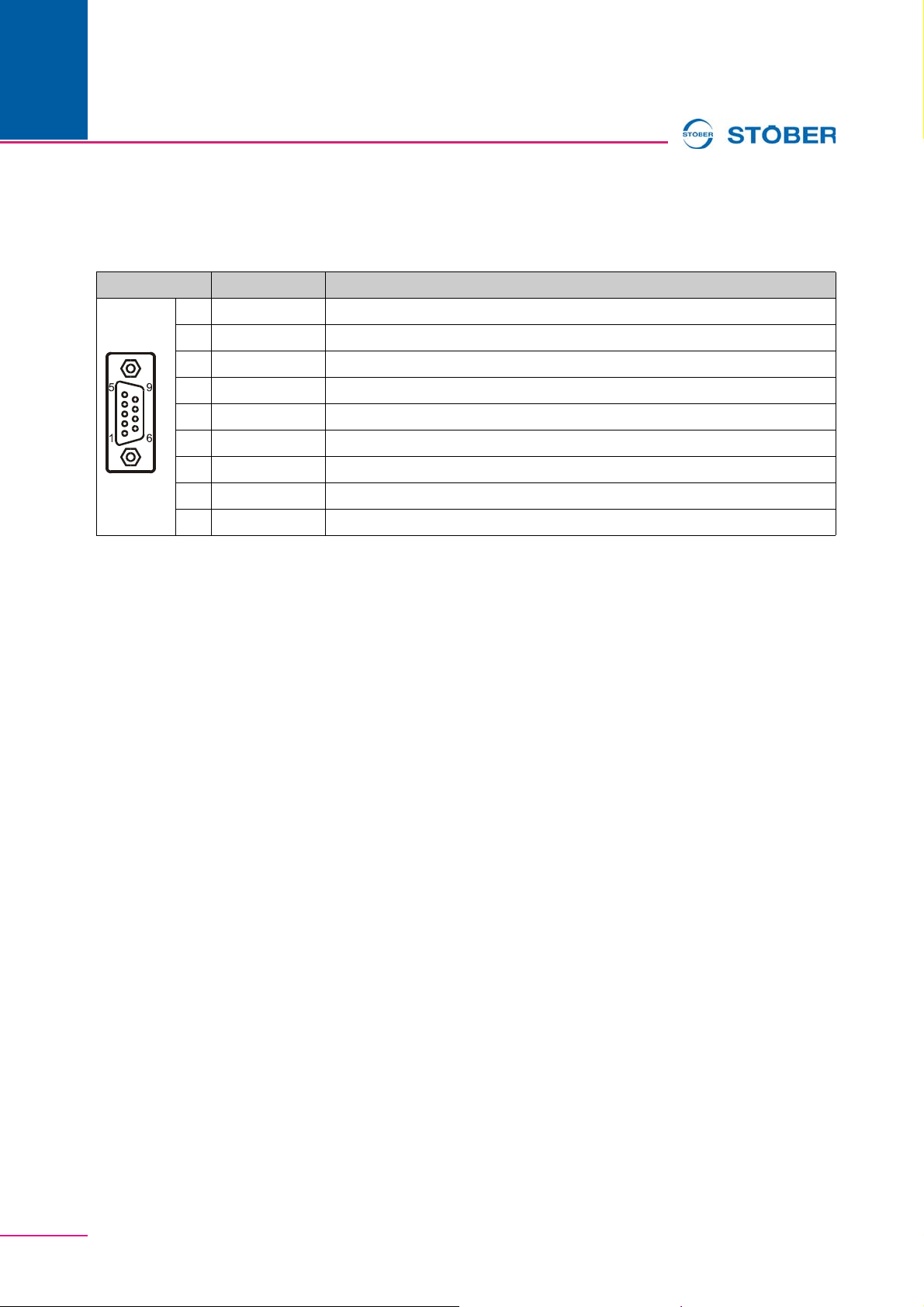
Terminal description X200
Pin Designation Function
1nc —
socket
2nc —
3 B RxD / TxD-P (send/receive data +)
4 RTS Direction control for repeater +
5 GND Ground to + 5 V
6 +5 V Power for terminating resistors
7nc —
8 A RxD / TxD-N (send/receive data -)
9nc —
WE KEEP THINGS MOVING
ID 442148.0314
Page 15

Address registers
Global Presence
Always up to date on the internet: www.stober.com
→ contact
• Technical Offices (TB) for advice and marketing in Germany
• Global presence for advice and marketing in about 25 countries
• Service Network Germany
• Service Network International
• STÖBER Subsidiaries:
Austria
STÖBER ANTRIEBSTECHNIK GmbH
Hauptstraße 41a
4663 Laakirchen
Fon +43 7613 7600-0
Fax +43 7613 7600-2525
E-Mail: [email protected]
www.stoeber.at
USA
STOBER DRIVES INC.
1781 Downing Drive
Maysville, KY 41056
Fon +1 606 7595090
Fax +1 606 7595045
eMail: [email protected]
www.stober.com
France
STÖBER S.a.r.l.
131, Chemin du Bac à Traille
Les Portes du Rhône
69300 Caluire et Cuire
Fon +33 4 78989180
Fax +33 4 78985901
eMail: [email protected]
www.stober.fr
Switzerland
STÖBER SCHWEIZ AG
Rugghölzli 2
5453 Remetschwil
Fon +41 56 496 96 50
Fax +41 56 496 96 55
eMail: [email protected]
www.stoeber.ch
China
STOBER CHINA
German Centre Beijing
Unit 2010, Landmark Tower 2,
8 North Dongsanhuan Road
Chaoyang District
100004 Beijing
Fon +86 10 65907391
Fax +86 10 65907393
eMail: [email protected]
www.stoeber.cn
Great Britain
STOBER DRIVES LTD.
Upper Keys Business Village
Keys Park Road, Hednesford
Cannock WS12 2HA
Fon +44 (0) 1543 458 858
Fax +44 (0) 1543 448 688
E-Mail: [email protected]
www.stober.co.uk
Japan
STOBER Japan
P.O. Box 113-002, 6 chome
15-8, Hon-komagome
Bunkyo-ku
Tokyo
Fon +81 3 5395-6788
Fax +81 3 5395-6799
eMail: [email protected]
www.stober.co.jp
Italy
STÖBER TRASMISSIONI S. r. l.
Via Risorgimento, 8
20017 Mazzo di Rho (Milano)
Fon +39 02 93909-570
Fax +39 02 93909-325
eMail: [email protected]
www.stoeber.it
Singapore
STOBER Singapore
50 Tagore Lane
#05-06B
Entrepreneur Centre
Singapore 787494
Fon +632 241 89 - 01/02/03/04/05
Fax +632 241 40 - 40/60
E-Mail: [email protected]
www.stober.sg
www.stober.com
Page 16
STÖBER ANTRIEBSTECHNIK GmbH + Co. KG
Kieselbronner Str. 12
75177 PFORZHEIM
GERMANY
Tel. +49 (0)7231 582-0
Fax. +49 (7231) 582-1000
E-Mail: [email protected]
24/h service hotline +49(0) 180 5 786 323
www.stober.com
Technische Änderungen vorbehalten
Errors and changes excepted
ID 442148.03
04/2012
442148.03
 Loading...