

Page 1

STMicrolectronics
ST7 Assembler
Linker
UM0144
User manual
Rev 2
June 2005
Page 2

BLANK
Page 3
Introduction
Thanks for choosing ST7! This manual describes how to use the ST7 Assembler-Linker to
develop applications for ST7 microcontrollers. The assembly tools described in this book form a
development system that assembles, links and formats your source code.
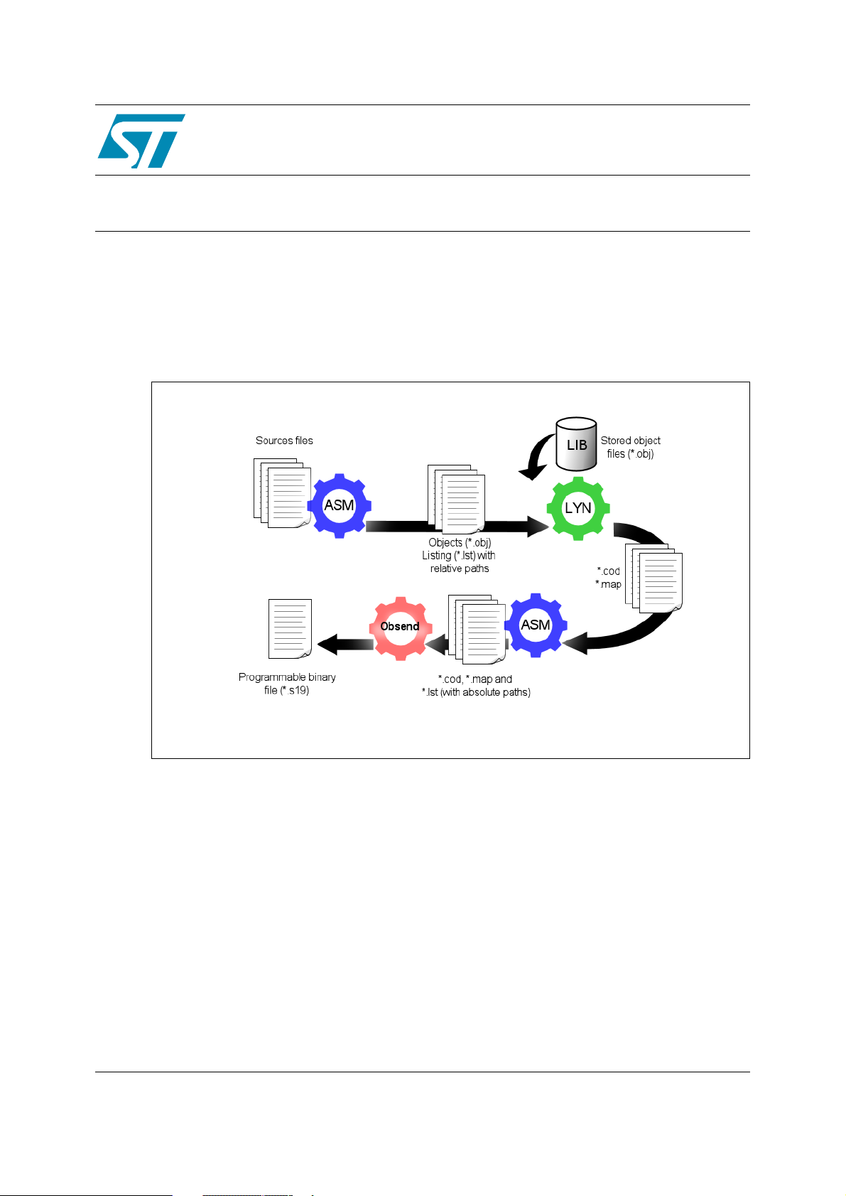
Figure 1. Schematic overview of the ST7 assembler toolset
UM0144
User Manual
ST7 Assembler Linker
The ST7 Assembler-Linker includes the following tools:
● Assembler (ASM): translates your source code (.ASM) written in assembly language, into
object code (.OBJ) specific to the target machine and an optional listing file (.LST).
● Linker (LYN): processes the object files (.OBJ) produced by the assembler, resolves all
cross-references between object files and locates all the modules in memory. The
resulting code is output in an object code file (.COD). In a second pass, the Assembler
uses these files to produce an object code file, map and listing with absolute paths.
● Obsend (OBS): translates the object code file to produce the final executable in a default
format (.FIN) or other format that you specify (e.g. ST S-record, Motorola S-record, Intel
Hex...).
● LIB (Librarian): The librarian enables you to store frequently used subroutines in one
location for use with any number of ST7 applications.
Rev 2
June 2005 UM0144 3/92
www.st.com
4
Page 4
ST7 Assembler Linker
Note: The utility file asli.bat automatically runs ASM, LYN, and OBSEND one after the other for you. Use this batch file only
if you have only one assembly source file ".ASM".
About the user manuals...
This manual provides information about producing an application executable for ST7 from your
application source code in Assembly language. Here, you will find:
● An overview of Assembly language for ST7
● Instructions for running the ST7 Assembler-Linker
● Descriptions of the Assembler output
For information on related subjects refer to the following documentation:
ST7xxxx Datasheet
ST7 Programming Manual
– full description of your ST7.
– a complete reference to ST7 Assembly language
Host PC system requirements
This tool has been designed to operate on a PC that meets the following:
● One of the following operating systems: Microsoft
®
or XP
● Intel
● Minimum RAM of 32 MB (64 MB recommended).
● 60 MB of free hard disk space to install all of the ST7 tools.
.
®
Pentium (or compatible) processor with minimum speed of 133 MHz.
®
Windows® 98, 2000, Millennium, NT®
Getting assistance
For more information, application notes, FAQs and software updates for all the ST
microcontroller development tools, check out the CD-ROM or our website:
www.st.com/mcu
For assistance on all ST microcontroller subjects, or for help developing applications that use
your microcontroller’s MSCI peripheral, refer to the contact list provided in
page 108. We’ll be glad to help you.
Product Support
on
4/92 UM0144
Page 5
ST7 Assembler Linker
Contents
1 Getting Started . . . . . . . . . . . . . . . . . . . . . . . . . . . . . . . . . . . . . . . . . . . . . . . . 7
2 ST7 Addressing Modes . . . . . . . . . . . . . . . . . . . . . . . . . . . . . . . . . . . . . . . . . 8
2.1 Overview of ST7 addressing modes . . . . . . . . . . . . . . . . . . . . . . . . . . . . . . . . 8
2.2 General instruction syntax . . . . . . . . . . . . . . . . . . . . . . . . . . . . . . . . . . . . . . . 8
2.3 Short and long addressing modes . . . . . . . . . . . . . . . . . . . . . . . . . . . . . . . . . 9
2.4 Inherent addressing mode . . . . . . . . . . . . . . . . . . . . . . . . . . . . . . . . . . . . . . . 9
2.5 Immediate operands . . . . . . . . . . . . . . . . . . . . . . . . . . . . . . . . . . . . . . . . . . . 10
2.6 Direct and indirect modes . . . . . . . . . . . . . . . . . . . . . . . . . . . . . . . . . . . . . . . 10
2.7 Indexed modes . . . . . . . . . . . . . . . . . . . . . . . . . . . . . . . . . . . . . . . . . . . . . . . .11
2.8 Relative mode . . . . . . . . . . . . . . . . . . . . . . . . . . . . . . . . . . . . . . . . . . . . . . . . .11
2.9 High, low addressing modes . . . . . . . . . . . . . . . . . . . . . . . . . . . . . . . . . . . . . .11
3 ST7 Assembler . . . . . . . . . . . . . . . . . . . . . . . . . . . . . . . . . . . . . . . . . . . . . . . 13
3.1 Overview . . . . . . . . . . . . . . . . . . . . . . . . . . . . . . . . . . . . . . . . . . . . . . . . . . . . 13
3.2 Source files . . . . . . . . . . . . . . . . . . . . . . . . . . . . . . . . . . . . . . . . . . . . . . . . . . 13
3.3 Assembly source code format . . . . . . . . . . . . . . . . . . . . . . . . . . . . . . . . . . . . 13
3.4 Segmentation . . . . . . . . . . . . . . . . . . . . . . . . . . . . . . . . . . . . . . . . . . . . . . . . 22
3.5 Macros . . . . . . . . . . . . . . . . . . . . . . . . . . . . . . . . . . . . . . . . . . . . . . . . . . . . . 26
3.6 Conditional assembly . . . . . . . . . . . . . . . . . . . . . . . . . . . . . . . . . . . . . . . . . . 29
3.7 Running the assembler . . . . . . . . . . . . . . . . . . . . . . . . . . . . . . . . . . . . . . . . . 30
4 Linker . . . . . . . . . . . . . . . . . . . . . . . . . . . . . . . . . . . . . . . . . . . . . . . . . . . . . . 35
4.1 What the linker does . . . . . . . . . . . . . . . . . . . . . . . . . . . . . . . . . . . . . . . . . . . 35
4.2 Invoking the linker . . . . . . . . . . . . . . . . . . . . . . . . . . . . . . . . . . . . . . . . . . . . . 35
4.3 Command line . . . . . . . . . . . . . . . . . . . . . . . . . . . . . . . . . . . . . . . . . . . . . . . . 35
4.4 Linking in detail . . . . . . . . . . . . . . . . . . . . . . . . . . . . . . . . . . . . . . . . . . . . . . . 36
4.5 The linker in more detail . . . . . . . . . . . . . . . . . . . . . . . . . . . . . . . . . . . . . . . . 39
5 OBSEND . . . . . . . . . . . . . . . . . . . . . . . . . . . . . . . . . . . . . . . . . . . . . . . . . . . . 41
5.1 What OBSEND does for you . . . . . . . . . . . . . . . . . . . . . . . . . . . . . . . . . . . . . 41
5.2 Invoking OBSEND . . . . . . . . . . . . . . . . . . . . . . . . . . . . . . . . . . . . . . . . . . . . 41
UM0144 5/92
Page 6
ST7 Assembler Linker
6 Librarian . . . . . . . . . . . . . . . . . . . . . . . . . . . . . . . . . . . . . . . . . . . . . . . . . . . . 45
6.1 Overview . . . . . . . . . . . . . . . . . . . . . . . . . . . . . . . . . . . . . . . . . . . . . . . . . . . . 45
6.2 Invoking the librarian . . . . . . . . . . . . . . . . . . . . . . . . . . . . . . . . . . . . . . . . . . . 45
6.3 Adding modules to a library . . . . . . . . . . . . . . . . . . . . . . . . . . . . . . . . . . . . . 46
6.4 Deleting modules from a library . . . . . . . . . . . . . . . . . . . . . . . . . . . . . . . . . . 46
6.5 Copying modules from a library . . . . . . . . . . . . . . . . . . . . . . . . . . . . . . . . . . 47
6.6 Getting details in your library . . . . . . . . . . . . . . . . . . . . . . . . . . . . . . . . . . . . 47
Appendix A Assembler Directives . . . . . . . . . . . . . . . . . . . . . . . . . . . . . . . . . . . . 48
Appendix B Error Messages . . . . . . . . . . . . . . . . . . . . . . . . . . . . . . . . . . . . . . . . . 78
Appendix C Revision History. . . . . . . . . . . . . . . . . . . . . . . . . . . . . . . . . . . . . . . . . 86
Appendix D Product Support. . . . . . . . . . . . . . . . . . . . . . . . . . . . . . . . . . . . . . . . . 87
6/92 UM0144
Page 7
ST7 Assembler Linker 1 Getting Started
1 Getting Started
Installing the ST7 Assembler-Linker
The ST7 Assembler-Linker is delivered as part of the ST7 toolset. A free installation package is available
at www.st.com/mcu. To install it:
1. Select
Tools” CD-ROM, or...
2. Run the installation executable that you have downloaded from the internet.
Note: Windows® 2000, NT® and XP®users must have administrator privileges to install certain
software components.
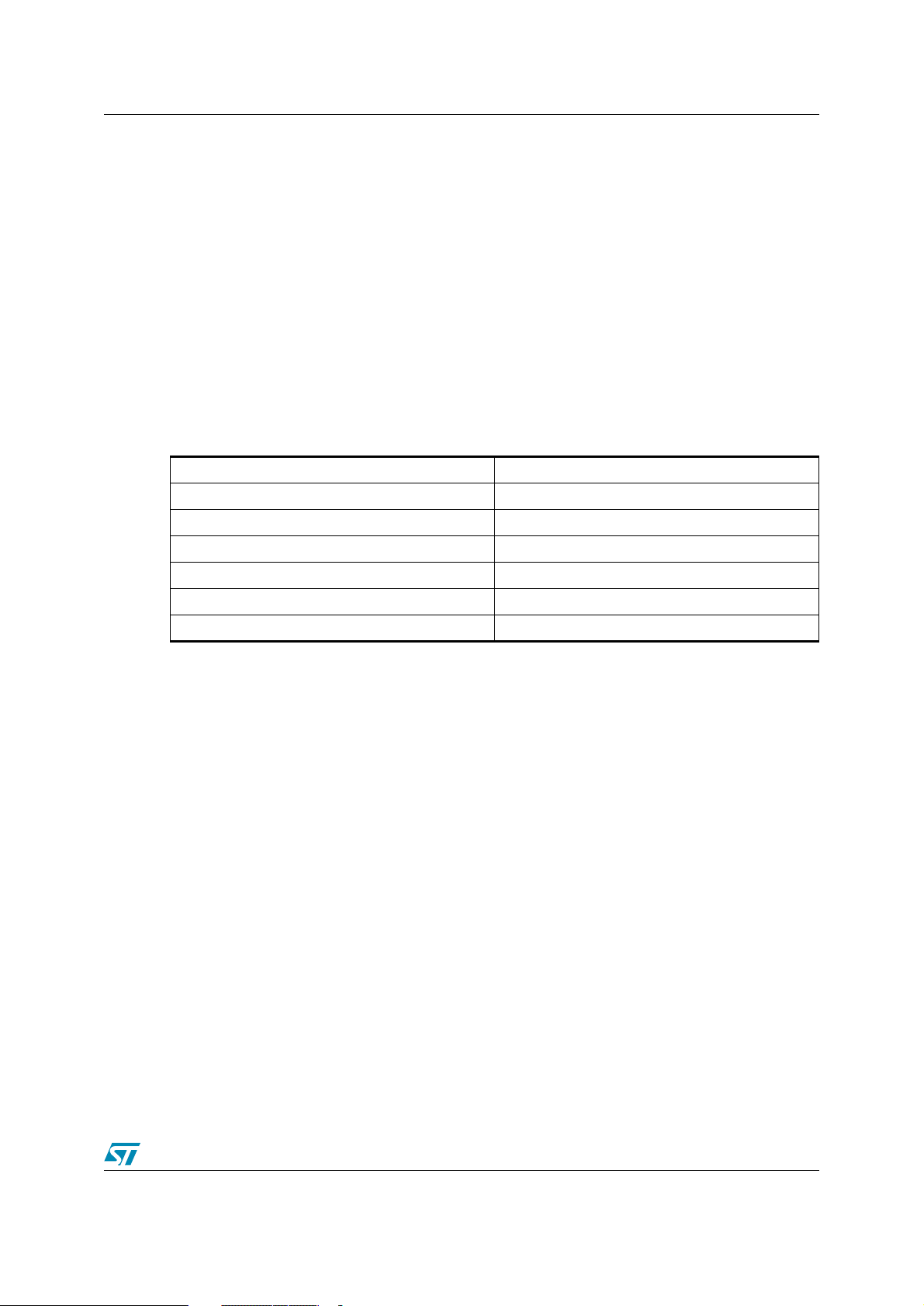
After installation, the installation directory should contain the following (
Table 1. Description of installed files
ASM.EXE ST7 Assembler
LYN.EXE ST7 Linker
OBSEND.EXE output file formatter
LIB.EXE librarian
ST7>ST7 toolchain
from the main menu of the “Microcontroller Development
Table 1
):.
ST7.TAB ST7 description files
ASLI.BAT batch file ASM+LYN+OBSEND
RELEASE_NOTES.PDF release notes
Up-to-date release notes are provided in PDF format. An additional file contains demonstration examples.
UM0144 7/92
Page 8
2 ST7 Addressing Modes ST7 Assembler Linker
2 ST7 Addressing Modes
2.1 Overview of ST7 addressing modes
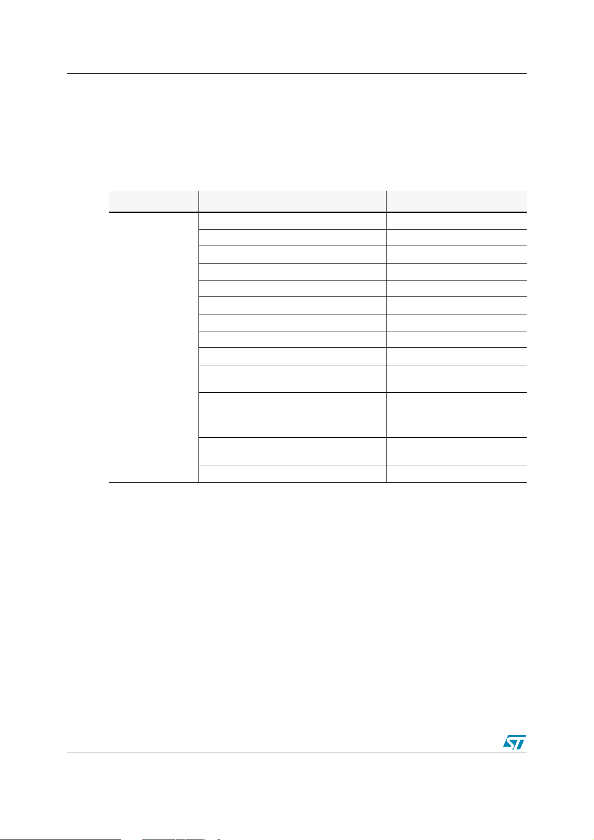
The ST7 assembler instruction set incorporates the following different addressing modes:
Table 2. ST7 Addressing modes
Instruction Set Addressing Mode Example
Inherent nop
Immediate ld A,#$F5
Direct (short address) ld A,$F5
Direct (long address) ld A,$F5C2
X or Y Indexed (no offset) ld A,(X)
X or Y Indexed (short offset) ld A,($F5,X)
X or Y Indexed (long offset) ld A,($F5C2,X)
ST7
Short Pointer Indirect (short pointed data) ld A,[$F5]
Short Pointer Indirect (long pointed data) ld A,[$F5.w]
Short Pointer Indirect (short pointed data) X
or Y Indexed
Short Pointer Indirect (long pointed data) X or
Y Indexed
Direct Relative (short offset) jrt $F5
Short Pointer Indirect Relative (short pointed
data)
Bit operation bset byte, #5
All ST7 addressing modes are described in full detail, with specific examples, in the
8-bit MCUs Programming Manual
. This chapter seeks only to give a brief explanation of the
main addressing mode types.
2.2 General instruction syntax
The ST7 instruction set provide a single source-coding model regardless of which components
are operands—the accumulator (A), an index register (X or Y), an 8-bit stack pointer (S) for
ST7, the condition code register (CC), or a memory location. For example, a single instruction,
ld, originates register to register transfers as well as memory to accumulator data movements.
ld A,([$F5],X)
ld A,([$F5.w],X)
jrt [$F5]
ST7 Family
8/92 UM0144
Page 9
ST7 Assembler Linker 2 ST7 Addressing Modes
Two-operand instructions are coded with destination operand appearing at first position. For
example:
lab01 ld A,memory ; load accumulator A with memory contents
lab02 ld memory,A ; load memory location with A contents
ld X,A ; load X with accumulator contents
2.3 Short and long addressing modes
For ST7 there are two addressing modes that differ in memory address size (i.e. one byte for
short mode and two bytes for long mode).
Because of these different addressing modes, the target address range of the operands will
depend upon the addressing mode chosen:
0-$FF for short addressing mode
$100-$FFFF for long addressing mode
Some instructions accept both long and short addressing modes, while others only accept one
or the other.
For example:
lab10 add A,memory ; accepts both types of addressing modes
lab11 inc memory ; accepts only short addressing mode
For ST7 instructions supporting both short and long formats, when external symbols are
referenced, long mode is chosen by the Assembler. For example:
EXTERN symb3 ;
symb1 equ $10 ;
...
ld A,symb1 ; short mode
ld A,symb3 ; long mode chosen
2.4 Inherent addressing mode
This concept is hardware-oriented, meaning that instruction operands are coded inside the
operation code. At the source coding level, operands are written explicitly.
Examples:
lab06 push A ; put accumulator A onto the stack
lab07 mul X,A ; multiply X by A
UM0144 9/92
Page 10
2 ST7 Addressing Modes ST7 Assembler Linker
2.5 Immediate operands
Immediate operands permit you to input a specific value for use with an instruction. They are
signaled by the use of a sharp sign (#) before the value.
Examples:
lab08 ld A,#1 ; load A with immediate value 1
lab09 bset memory,#3 ; set bit #3 in memory location
btjt memory,#3,label ;
The range for an 8-bit immediate operand is from 0 to 255.
2.6 Direct and indirect modes
A direct addressing mode means that the data byte required to do the operation is found by
its memory address, which follows the op-code.
An indirect addressing mode means that the data byte required to do the operation is found
by its memory address which is located in memory (pointer). The pointer address follows the
op-code.
This last group consists of memory indirect variants:
● short indirect (short pointed data),
● long indirect (long pointed data),
● short indirect indexed (short pointed data),
● long indirect indexed (long pointed data),
For ST7 devices, the address specified must always be in page 0 (i.e. its address must be less
than $100). Examples:
ld A,[80] ; short indirect
test bit #3 of memory and
jump if true (set)
ld A,[80.b] ; short indirect
ld A,[80.w] ; long indirect
lab12 equ 80
ld A,([lab12],X) ; short indirect X-indexed
ld A,([lab12.b],X) ; short indirect X-indexed
ld A,([lab12.w],Y) ; long indirect Y-indexed
To make the distinction between short and long indirect addressing mode, the suffix.w is
specified to indicate that you want to work in long indirect mode (this is also true for indexed
addressing mode). Implicitly, if nothing is specified, the short indirect addressing mode is
assumed.
For ST7 devices, you can also use.b to specify short indirect addressing mode (as with the
indexed addressing mode).
10/92 UM0144
Page 11
ST7 Assembler Linker 2 ST7 Addressing Modes
2.7 Indexed modes
The ST7 hardware supports four types of indexed mode:
● indexed without offset,
● indexed with a 8-bit unsigned offset (range [0 ,255]),
● indexed with a 16-bit offset,
The source coding syntax is:
(X) or (Y) for no-offset indexing.
(offset,X) or (offset,Y)for indexed with offset.
Some instructions (such as ld A or add) support the first three types of indexed mode. Some
ST7 instructions (such as inc) only support the first two types (i.e. indexed without offset and
indexed with 8-bit unsigned offset). Examples:
ld A,(X) ; no-offset mode
ld A,(0,X) ; 8-bit offset mode
ld A,(127,X) ; 8-bit offset mode
ld A,(259,X) ; 16-bit offset mode
2.8 Relative mode
This addressing mode is used to modify the Program Counter (PC) register value by adding an
8-bit signed offset to it (i.e. in the range -128 to +127). The relative addressing mode is made
up of two sub-modes:
● relative (direct)—where the offset is following the op-code.
● relative (indirect)—where the offset is defined in memory, whose address follows the op-
code.
Relative mode is used by the instructions JRxx, CALLR, and BTJx.
At source coding level, the target label is specified (and the assembler computes the
displacement).
2.9 High, low addressing modes
In some instances, it may be necessary to access the highest part of an address (8 highest
bits) or the lowest part of an address (8 lowest bits) as well. For this feature, the syntax is the
following one:
<expression>
where expression is:
symbol.H (highest part) , or
symbol.L (lowest part).
UM0144 11/92
Page 12
2 ST7 Addressing Modes ST7 Assembler Linker
Examples:
lab12 equ $0012
nop
ld A,#lab12.h ; load A with $00
ld A,#lab12.l ; load A with $12
For more information about each instruction and the various addressing modes, refer to the
ST7 Programming Manual
, which can be downloaded from the Internet at www.st.com/mcu.
12/92 UM0144
Page 13
ST7 Assembler Linker 3 ST7 Assembler
3 ST7 Assembler
3.1 Overview
The ST7 Assembler program is a cross-assembler, meaning that it produces code for a target
machine—an ST7 microprocessor—which is different from the host machine.
The assembler turns your source code files into relocatable object modules ready for linking.
During the process, it checks for many different types of errors. These errors are recorded in an
ASCII file called cbe.err. (Note that the linker also writes to this file.) Error messages are
explained in on page 78.
To produce code ready for execution, you must run the assembler (ASM), the linker (LYN), and
the object code formatter (OBSEND).
3.2 Source files
Source program code is written in the ST7 Assembler language and is saved in an ASCII text
file named source file. A source file has the extension .asm. It is made up of lines, each of
which is terminated by a new line character.
For a complete reference to the ST7 Assembler language, refer to the
Manual
.
3.3 Assembly source code format
The first line of an assembly source code file is reserved for specifying the *.tab file for the
target processor. You cannot put other instructions or comments in this line.
Use this line to specify the directory location of the *.tab file. If the directory is not specified, by
default the Assembler searches first in the current directory, then in the directory where the
Assembler’s executable is located.
The '.tab' suffix may be left out—as the assembler only looks for this file type.
For example, the first line of your source code might look like:
c:\st7tools\asm\st7\
If the file st7.tab can't be found in the specified or default directories, then an error is
produced and assembly is aborted.
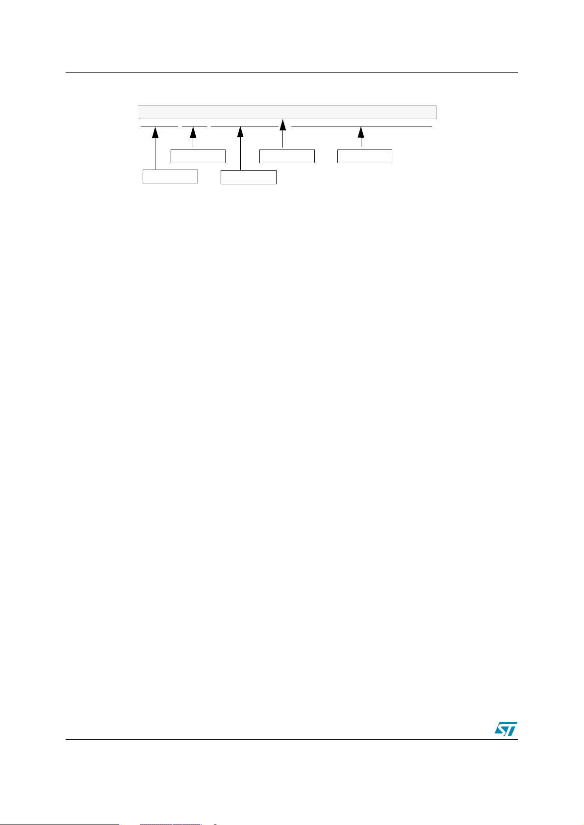
The rest of the source code lines have the following general format:
[label[:]]<space>[opcode]<space>[operand]<space>[;comment]
where <space> refers to either a SPACE ($20) or a TAB ($09) character.
ST7 Programming
All four fields may be left blank, but the <space> fields are mandatory unless:
● the whole line is blank, or
● the line begins as a comment, or
● the line ends before the remaining fields.
UM0144 13/92
Page 14
3 ST7 Assembler ST7 Assembler Linker
For example:
examp ld A,$ffff ; long addressing mode
label
The next sections describe the main components of a source code file.
3.3.1 About labels
Label structure
Labels must start in column one. A label may contain up to 30 of any of the following
characters:
● Upper Case letters (A-Z)
● Lower case letters (a-z)
● Digits (0-9)
● Underscore (_)
The first letter of a label must be a letter or an underscore. Note that upper and lower case are
treated differently because the assembler is case sensitive.
Upon assembly, any label that exceeds 30 characters is truncated and a warning alerts the
user that this has occurred. When truncated, if two of more labels have the same name, a
phase inconsistency error is generated.
When labels are defined, several attributes are defined along with the value.
opcode
operand
separator
comments
These are:
● Size (Byte, Word or Long)
● Relativity (Linker Relative or Absolute)
● Scope (Internally or Externally defined)
The function of each attribute is explained in the following sections.
Label size
Defining a label’s size allows the assembler to determine what kind of addressing mode to
choose even if the value associated with the label is undefined.
The default size of the memory location for a label is word (2 bytes). Whenever the label has no
suffix, then the default size is assumed. The directives BYTES, WORDS and LONGS (4
bytes) allow you to change the default.
Regardless of the default size, you can define the size for a specific label by adding a suffix to
it: .b for byte, .w for word and .l for long. The suffix is not used when the label is referred to.
Using of any suffixes other than .b, .w and .l will result in an error upon assembly.
14/92 UM0144
Page 15
ST7 Assembler Linker 3 ST7 Assembler
For example:
lab equ 0
label1.b equ 5
label2.l equ 123
segment byte at: 80 ‘ram’
bytes
count ds.b
pointer ds.w
; word-size label (default)
; byte-size label
; long label
; force the size of the label to
; bytes
; byte-size label
; byte-size label with a word-size
; space reserved at this address
Label relativity
There are two sorts of labels:
●
Absolute
labels are usually assigned to constants, such as IO port addresses, or common
values used within the program.
●
Relative
labels are defined as (or derived from) an
the position of some program code. They are exclusively used for labels defined within
pieces of program or data.
For example:
absolute
labels and
relative
labels.
external
label or a label derived from
lab equ 0 ; absolute label ‘count’
ioport equ $8000 ; absolute word label ‘ioport’
segment ‘eprom’
start ld X,#count
ld A,#’*’
loop ld ioport,A
dec X
jrne loop
stop jp stop ; then loop for ever
Only the linker can sort out the actual address of the code, as the assembler has no idea how
many segments precede this one in the class. At assembly time, labels such as 'start' or 'loop'
are actually allocated 'blank' values ($0000). These values will be filled later by the linker.
Labels such as 'count' or 'ioport', which were defined absolutely will be filled by the assembler.
Source code lines that have arguments containing relative labels are marked with an 'R' on the
listing, showing that they are 'linker relative'. Segments are discussed in
Section 3.4
on
page 22.
UM0144 15/92
Page 16
3 ST7 Assembler ST7 Assembler Linker
Label scope
Often, in multi-module programs, a piece of code will need to refer to a label that is actually
defined in another module. To do this, the module that exports the label must declare it
PUBLIC, and the module which imports the label must declare it EXTERN. The two directives
EXTERN and PUBLIC go together as a pair.
Most labels in a program will be of no interest for other pieces of the program—these are
known as 'internal' labels since they are only used in the module where they are defined.
Labels are 'internal' by default.
Here are two incomplete example modules that pass labels between them:
module 1
EXTERN _sig1.w ; import _sig1
EXTERN _sig2.w ; import _sig2
PUBLIC _handlers ; export _handlers
segment byte ‘P’
_handlers: ; define _handlers
jp _sig1 ; refer to _sig1
jp _sig2 ; refer to _sig2
end
module 2
EXTERN _handlers.w ; import _handlers (addr. is a word)
PUBLIC _sig2 ; export _sig2
segment byte ‘P’
_sig2: ; define _sig2
...
call _handlers ; refer to _handlers
...
ret
end
As you can see, module 1 refers to the '_sig2' subroutine which is defined in module 2. Note
that when module 1 refers to the '_sig2' label in an EXTERN directive it specifies a WORD size
with the '.w' suffix. Because the assembler cannot look up the definition of '_sig2' it has to be
told its address size explicitly. It doesn't need to be told relativity: all external labels are
assumed to be relative.
Absolute labels declared between modules should be defined in an INCLUDE file that is called
by all modules in the program; this idea of using INCLUDE files is very important since it can
reduce the number of PUBLIC symbols—and therefore the link time—significantly.
Lines in the source code listing which refer to external labels are marked with an X and given
'empty' values for the linker to fill.
16/92 UM0144
Page 17
ST7 Assembler Linker 3 ST7 Assembler
As a short cut, labels may be declared as PUBLIC by preceding them with a '.' at their
definition. If this is done the label name need not be given in a PUBLIC directive. For example,
the following code fragment declares the label 'lab4' as PUBLIC automatically:
lab3 ld A,#0
ret
.lab4 nop
ret
3.3.2 About opcodes
The Opcode field may serve three different purposes. It may contain:
● The opcode mnemonic for an assembly instruction,
● The name of a directive,
● The name of a macro to be invoked.
Opcodes must be separated from the preceding field (i.e. label, if there is one) by a space or a
tab.
A comprehensive Opcode description can be found in the
Macros are discussed in
Directives are discussed in on page 48.
3.3.3 About operands
Operands may be any of the following:
● Numbers and addresses,
● String and character constants,
● Program Counter references,
● Expressions.
The following paragraphs explain how to use these types of operands.
Number and address representation
By default, the representation of numbers and addresses follows the MOTOROLA syntax.
When you want to use hexadecimal number with instructions or labels, they must be preceded
by $. When nothing is specified, the default base is decimal.
For example:
lab03 equ 10 ; decimal 10
Section 3.5
on page 26.
ST7 Programming Manual
.
lab04 equ $10 ; hexadecimal 10
ld A,$ffff ; long addressing mode
ld A,#$cb ; immediate addressing mode
ld A,#100 ; decimal representation
UM0144 17/92
Page 18
3 ST7 Assembler ST7 Assembler Linker
You can change the Motorola format representation by using directives (.INTEL, .TEXAS) to
indicate the new setting format. For more information, refer to on page 48.
Caution: Addresses for SEGMENT definition are always given in hexadecimal:
segment byte at: 100-1FF 'test'
The segment 'test' is defined within the 256-511 address range.
Numeric constants and radix
Constants may need special characters to define the radix of the given number.
The assembler supports the MOTOROLA format by default. INTEL, TEXAS, ZILOG formats
are also available if the format is forced by .INTEL .TEXAS or .ZILOG directives.
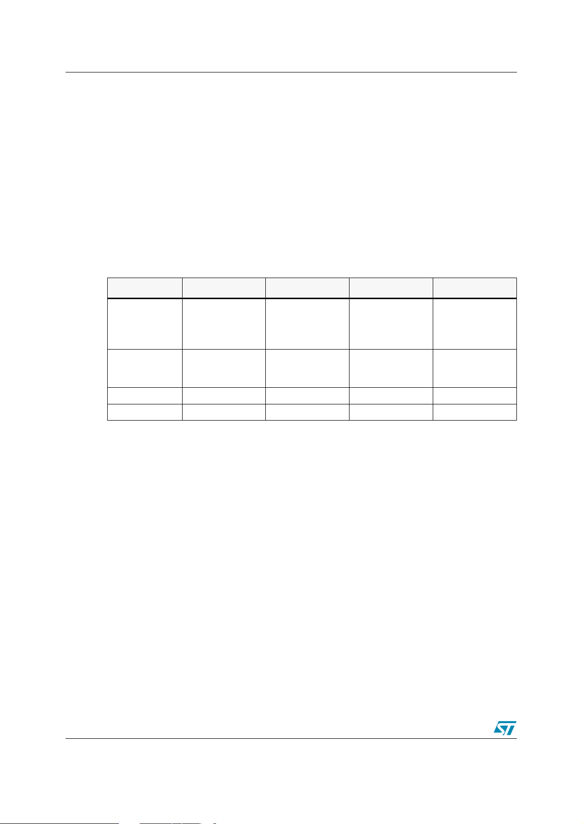
page 18 shows a summary of these formats.
Note: Decimal constants are always the default, and require no special characters.
Table 3. Numeric constants and radix formats
Format Hex Binary Octal Current PC
Motorola $ABCD or &ABCD %100 ~665 *
Ta bl e 3
(use MULT for
MU LTIPLY)
on
Intel 0ABCDh 100b 665o
or
665q
Texas >ABCD ?100 ~665 $
Zilog %ABCD %(2)100 %(8)665 $
$
String constants
String constants are strings of ASCII characters surrounded by double quotes.
For example:
“This is an ASCII string”
ASCII character constants
The assembler's arithmetic parser also handles ASCII characters in single quotes, returning
the ASCII of the given character(s).
For example:
‘A’ $41
‘6’ $06
‘AB’ $4142
18/92 UM0144
Page 19
ST7 Assembler Linker 3 ST7 Assembler
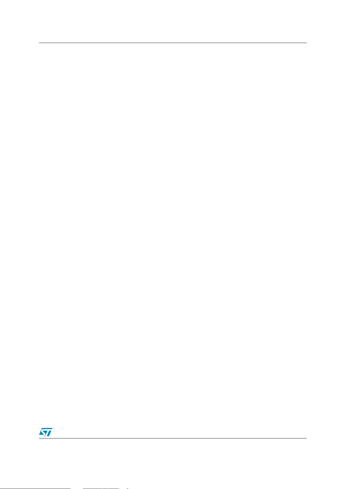
Up to 4 characters may be used within a single pair of quotes to give a long constant. The
following special sequences are used to denote special characters:
‘\b’ $7F backspace
‘\f’ $0C formfeed
‘\n’ $0A linefeed
‘\r’ $0D carriage return
‘\t’ $09 tabulation
‘\\’ $5C slash
‘\’ $27 single-quote
‘\0’ $00 null
‘\”’ $22 double-quote
Program counter reference
The current value of the program counter (PC) can be specified by an asterisk "*".
For example:
lab05 jra *
Expressions and operators
Expressions are numeric values that may be made up from labels, constants, brackets and
operators.
Labels and constants have been discussed in previous paragraphs.
Arithmetic brackets are allowed up to 8 nested levels—the curly braces {} are used instead
of the common “()” because instructions may use a parenthesis to denote indexed addressing
modes.
UM0144 19/92
Page 20
3 ST7 Assembler ST7 Assembler Linker
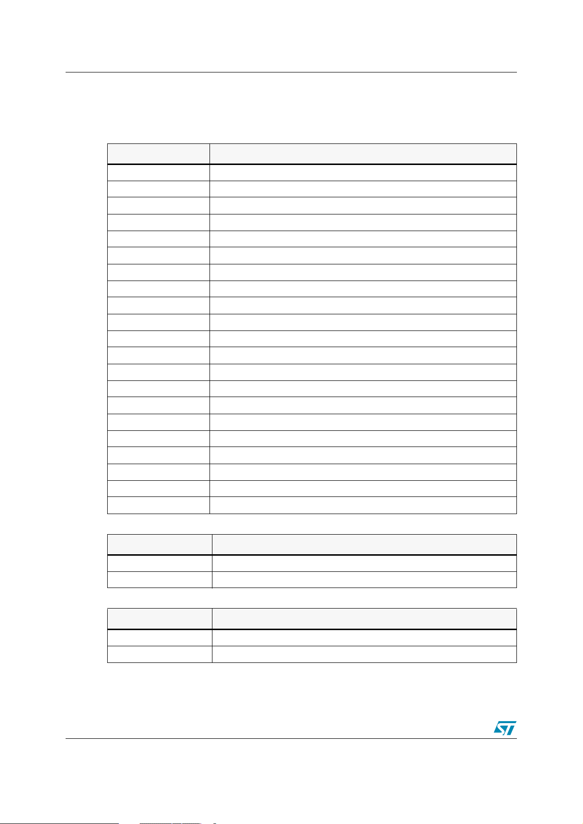
Operators have 4 levels of precedence. Operators in level #1 (listed in
precedence over operators in level #2 (listed in
Ta bl e 5
), and so on. In each level, operators
have same precedence—they are evaluated from left to right.
Table 4. Level 1 operators
Operation Result, level #1
-a negated a
a and b logical AND of A and B
a or b logical OR of A and B
a xor b logical XOR of A and B
a shr b a shifted right b times
a shl b a shifted left b times
a lt b 1 if a<b, else 0
a gt b 1 if a>b, else 0
a eq b 1 if a=b, else 0
a ge b 1 if a>=b, else 0
a ne b 1 if a unequal b, else 0
high a a/256, force arg to BYTE type
low a a MOD 256, force arg to BYTE type
offset a a MOD 65536, force arg to WORD*16 type
Ta b le 4
) take
seg a a/65536, force arg to WORD*16 type
bnot a invert low 8 bits of a
wnot a invert low 16 bits of a
lnot a invert all 32 bits of a
sexbw a sign extend byte to 16 bits
sexbl a sign extend byte a to 32 bits
sexwl a sign extend word to 32 bits
Table 5. Level 2 operators
Operation Result, level #2
a/b a divided by b
a div b a divided by b
Table 6. Level 3 operators
Operation Result, level #3
a * b a multiplied by b
a mult b as above for motorola (character * is reserved)
20/92 UM0144
Page 21
ST7 Assembler Linker 3 ST7 Assembler
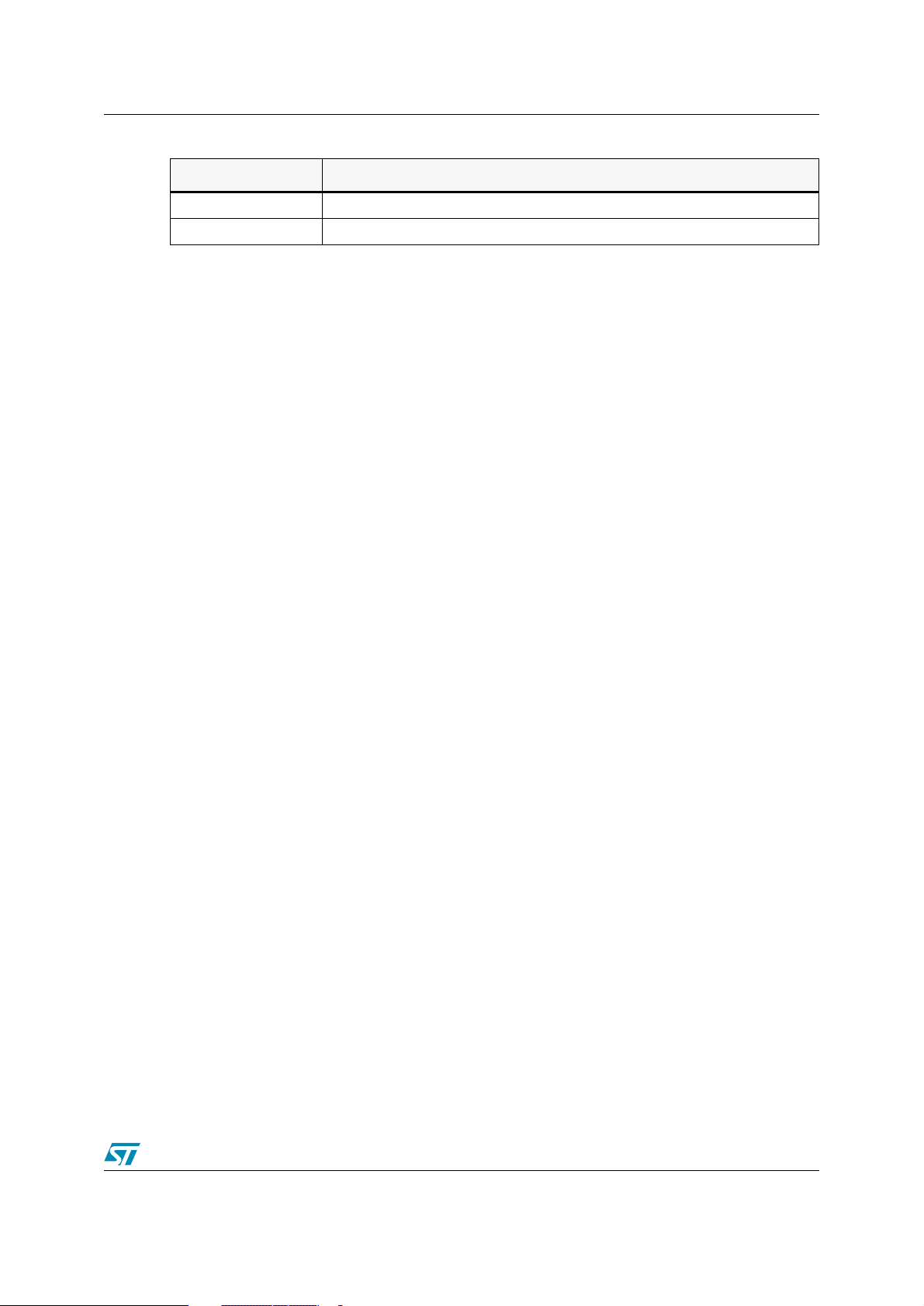
Table 7. Level 4 operators
Operation Result, level #4
a-b a minus b
a+b a plus b
Operator names longer than one character must be followed by a space character. For
example, '1 AND 2' is correct, '1AND2' is not.
Place the curly braces { } around arithmetic expressions.
Also, always use curly braces at the top-level, when defining a numeric expression. Not doing
so may produce unexpected results.
Wrong syntax:
#define SIZE 128
DS.W SIZE+1
#IF SIZE eq 1
#ENDIF
Correct syntax:
#define SIZE 128
DS.W {SIZE+1} ; OK
#IF {SIZE eq 1} ; OK
#ENDIF
3.3.4 Comments
Comments are preceded by a semicolon. Characters following a semicolon are ignored by the
assembler.
3.3.5 A source code example
Below is an example of a short source code.
st7/
; Wrong, syntax error
; Wrong, same as #IF SIZE
; small example module showing source formats
ioport equ $8000 ; 8 bit I0 port A
handshake equ $9000 ; write xx here to strobe
segment 'program'
start ld a,#0 ; zero counter
loop ld ioport,x ; store into ioport
UM0144 21/92
Page 22
3 ST7 Assembler ST7 Assembler Linker
segment word at: FFFC 'code'
WORD start
end
Don't worry if some directives don't make sense yet; they will be covered soon. Also, take
special notice of the SEGMENT directive.
3.4 Segmentation
Segments are very important. You have to understand segments before you can use the
assembler. Take the time to understand them now and you'll save yourself a lot of puzzling
later.
Segmentation is a way of 'naming' areas of your code and making sure that the linker collates
areas of the same name together in the same memory area, whatever the order of the
segments in the object files. Up to 128 different segments may be defined in each module.
The segment directive itself has four arguments, separated by spaces:
[<name>] SEGMENT [<align>] [<combine>] '<class>' [cod]
For example:
FILE1:
st7/
BYTES
segment byte at: 80-FF ‘RAM0’
counter.b ds.b ; loop counter
address.b ds.w ; address storage
ds.b 15 ; stack allocation
stack ds.b ; stack grows downward
segment byte at: E000-FFFF ‘eprom’
ld A,#stack
ld S,A ; init stack pointer
end
22/92 UM0144
Page 23
ST7 Assembler Linker 3 ST7 Assembler
FILE2:
st7/
segment ‘RAM0’
serialtemp ds.b
serialcou ds.b
WORDS
segment ‘eprom’
serial_in ld A,#0
end
In the preceding example, FILE1 and FILE2 are two separate modules belonging to the same
program. FILE1 introduces two classes: 'RAM0' and 'eprom'. The class-names may be any
names you choose up to 30 characters.
The first time a class is used—introduced—you have to declare the default alignment, the start
and the end addresses of the class, and of course, the name of the class.
Users generally specify a new class for each 'area' of their target system.
In the examples above, the user has one class for the 128 bytes of on-chip RAM from 0080 to
00FF ('RAM0') and another for the 'eprom'.
The code is stored from E000 to FFFF ('eprom'). You have to supply all this information the
very first time you use a new class, otherwise only the class-name is necessary, as in FILE2.
3.4.1 Parameters
The following paragraphs describe each argument in detail.
Name
The <name> argument is optional; it can contain a name of up to 12 characters. If it does, then
all segments with the same name are grouped together within their class, in the order that new
names are defined.
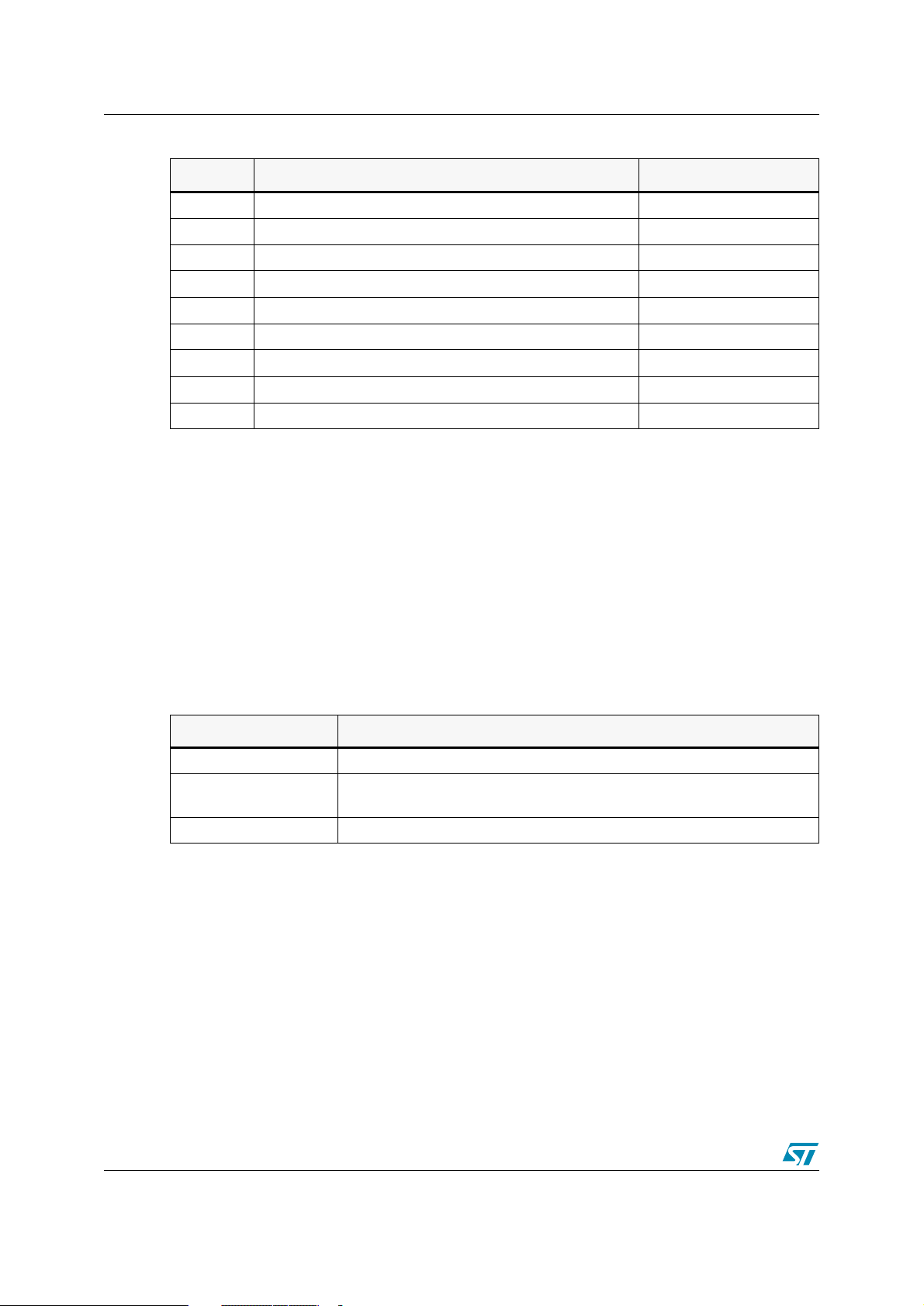
Align
The <align> argument defines the threshold on which each segment must start. The default
is the alignment specified at the introduction of the class (if none is specified in the class
introduction then para alignment is assumed), although the alignment types described in
Ta bl e 8
are allowed to be specified overriding the default.
UM0144 23/92
Page 24
3 ST7 Assembler ST7 Assembler Linker
Table 8. Alignment types
Type Description Examples
byte Any address
word Next address on boundary 1001->1002
para Next address on 16-byte boundary 1001->1010
64 Next address on 64-byte boundary 1001->1040
128 Next address on 128-byte boundary 1001->1080
page Next address on 256-byte boundary 1001->1100
long Next address on 4-byte boundary 1001->1004
1k Next address on 1k-byte boundary 1001->1400
4k Next address on 4K-byte boundary 1001->2000
Looking back to our example on
page 22
, you should now be able to see that the 'RAM0'
class will allocate 80 to counter, 81 to address, 92 to stack in FILE1, and when the linker
meets the segment in FILE2 of the same class, serialtemp will be allocated 93, and
serialcou 94. The same processing happens to the two 'eprom' class segments—the
second, in FILE2, will be tacked on to the end of the first in FILE1. If the FILE2 'eprom' class
segment had specified, say, the long align type instead of the default byte, then that segment
would have been put on the next long-word boundary after the end of the FILE1 'eprom'
class segment.
Combine
The <combine> argument tells the assembler and linker how to treat the segment. There are
three types to handle it:
Table 9. Combine types
Type Description
at:X[-Y] Starts a new class from address X [to address Y]
common All common segments that have the same class name will start at the same
address. This address is determined by the linker.
<none> Follows on from end of last segment of this class.
The at-type <combine> must be used at the introduction of a class, only once.
The at-type <combine> must have one argument: the start address of the class, and may
optionally be given the end address (or limit) of the class too. If given, the linker checks that no
items in the class have gone over the limit address; if this does occur, a warning is issued at link
time. The hexadecimal numbers X and Y should not have radix specifiers.
All common-type <combine> segments that have the same class name will start at the same
address. The linker keeps track of the longest segment. common segments can be used for
sharing data across different applications.
24/92 UM0144
Page 25
ST7 Assembler Linker 3 ST7 Assembler
For example:
st7/
dat1 segment byte at: 10 'DATA'
ds.w
com1 segment common 'DATA'
.lab1 ds.w 4
com1 segment common 'DATA'
.lab2 ds.w 2
com2 segment common 'DATA'
.lab3 ds.w
com2 segment common 'DATA'
.lab4 ds.w 2
dat2 segment 'DATA'
.lab5 ds.w 2
end
The values for labels lab1, lab2, lab3, lab4, and lab5 are 12, 12, 1A, 1A and 1E,
respectively.
Note: Since you can't specify both
the exact location of commons is to insert an empty
common
declaration.
For example:
com1 segment byte at: 10 'DATA'
com1 segment common 'DATA'
...
com1 segment common 'DATA'
...
cod parameter, output file control
The last field of a SEGMENT directive controls where the linker places the code for a given
class. When introducing a class, if this field is not specified, the code for this class will be sent
to the normal, default.COD file by the linker. If the [cod] file is given a number between 0 and
9 then all code generated under the class being introduced will be sent to a different '.COD' file
by the linker.
at
and
common
combines simultaneously, the only way to specify
at
combine segment before the first
If the linker produces a file called 'prog.cod', for example, then all code produced under
classes with no [cod] field will go into that file, as normal.
UM0144 25/92
Page 26
3 ST7 Assembler ST7 Assembler Linker
If one class is introduced with a [cod] field of 1, though, then all code produced under that
class is sent instead to a file prog_1.cod. The code produced under the other classes is sent
on as usual to prog.cod.
Using this scheme, you can do bank switching schemes quickly and directly, even when
multiple EPROMs share the same addressing space. Simply allocate each EPROM class of its
own, and introduce each class with a different [cod] field. This will result in the linker collating
EPROM's contents into a different .COD file for you to OBSEND independently.
For example:
segment byte at:8000-BFFF 'eprom1' 1
segment byte at:8000-BFFF 'eprom2' 2
3.4.2 Copying code
It sometimes happens that you need to copy a block of code from EPROM to RAM. This
presents some difficulties because all labels in that piece of code must have the RAM
addresses, otherwise any absolute address references in the code will point back to the
EPROM copy.
In this case, it helps to specify a class for execution, and use a different class for storage, as
in the following example:
label1: nop
The code starting from 'label1' will be stored in the 'code' class as usual, but all the labels in
that special segment will be given addresses in the 'ram' class, and memory will also be
reserved in the ram class for the contents of the special segment.
3.5 Macros
Macros are assembly-time subroutines.
When you call an execution-time subroutine you have to go through several time-consuming
steps: loading registers with the arguments for the subroutine, having saved and emptied out
the old contents of the registers if necessary, pushing registers used by the subroutine (with its
attendant stack activity) and returning from the subroutine (more stack activity) then popping off
preserved registers and continuing.
Although macros don't get rid of all these problems, they can go a long way toward making your
program execute faster than using subroutines—at a cost. The cost is program size.
Each time you invoke a macro to do a particular job, the whole macro assembly code is
inserted into your source code.
segment byte at: 0 'code'
segment byte at: 8000 'ram'
segment 'ram>code'
This means there is no stacking for return addresses—your program just runs straight into the
code; but it's obviously not feasible to do this for subroutines above certain size.
26/92 UM0144
Page 27
ST7 Assembler Linker 3 ST7 Assembler
The true use of macros is in small snippets of code that you use repeatedly— perhaps with
different arguments—which can be formalized into a 'template' for the macros' definition.
3.5.1 Defining macros
Macros are defined using three directives: MACRO, MEND and LOCAL.
The format is:
<macro-name>MACRO [parameter-1][, parameter-2 ...]
[LOCAL] <label-name>[, label-name ...]]
<body-of-macro>
MEND
For example:
add16 MACRO first,second,result
ld A,first
adc A,second
ld result,A
MEND
The piece of code of the example might be called by:
add16 index,offset,index
which would add the following statements to the source code at that point:
ld A,index
adc A,offset
ld index.X,A
Note that the formal parameters given in the definition have been replaced by the actual
parameters given on the calling line. These new parameters may be expressions or strings
as well as label names or constants. Because they may be complex expressions, they are
bracketed when there is any extra numeric activity; this is to make sure they come out with the
precedence correctly parsed.
Macros do not need to have any parameters. You may leave the MACRO argument field blank
(and, in this case, give no parameters on the calling line).
There is one further problem: because a macro may be called several times in the same
module, any labels defined in the macro will be duplicated. The LOCAL directive gets around
this problem:
UM0144 27/92
Page 28
3 ST7 Assembler ST7 Assembler Linker
For example:
getio MACRO
LOCAL loop
loop ld A,$C000
jra loop
MEND
This macro creates the code for a loop to await IO port at $C000 to go low. Without the LOCAL
directive, the label 'loop' would be defined as many times as the macro is called, producing
syntax errors at assembly time.
Because it's been declared LOCAL at the start of the MACRO definition, the assembler takes
care of it. Wherever it sees the label 'loop' inside the macro, it changes the name 'loop' to
'LOCXXXX' where XXXX is a hex number from 0000 to FFFF.
Each time a local label is used, XXXX is incremented. So, the first time the getio macro is
called, 'loop' is actually defined as 'LOC0', the second time as 'LOC1' and so on, each of these
being a unique reference name. The reference to 'loop' in the 'if' statement is also detected
and changed to the appropriate new local variable.
The directives in
Ta bl e 1 0
are very useful, in conjunction with macros:
Table 10. Some useful directives
Directive Usage
#IFB To implement macro optional parameters.
#IFDEF To test if a parameter is defined.
#IFLAB To test if a parameter is a label.
#IFIDN To compare a parameter to a given string.
3.5.2 Parameter substitution
The assembler looks for macro parameters after every space character. If you want to embed a
parameter, for example, in the middle of a label, you must precede the parameter name with an
ampersand '&' character, to make the parameter visible to the preprocessor. For example, if we
have a parameter called 'param'.,
dc.w param
it works as expected, but the ampersand is necessary on:
label¶m:nop
label¶m&_¶m:nop
Otherwise 'labelparam' would be left as a valid label name; If the macro parameter 'param'
had the value '5', then 'label5' and 'label5_5' would be created.
28/92 UM0144
Page 29
ST7 Assembler Linker 3 ST7 Assembler
3.6 Conditional assembly
Conditional assembly is used to choose to ignore or select whole areas of assembler code.
This is useful for generating different versions of a program by setting a particular variable in an
INCLUDE file that forces the use of certain pieces of code instead of others.
3.6.1 #IF, #ELSE and #ENDIF directives
There are three main directives used to perform conditional assembly, as shown in
Ta bl e 1 1
.
Table 11. Summary of assembly directives
Directive Usage
#IF marks the start of the conditional and decides whether the following zone will be
assembled or not.
#ELSE optionally reserves the condition of the previous #IF for the following zone.
#ENDIF marks the end of the previous #IF's.
The condition given with the '#IF' may take the form of any numeric expression. The rule for
deciding whether it resolves to 'true' or 'false' is simple: if it has a zero value then it's false, else
it's true. These directives should NOT start at column 1 of line, reserved for labels. For
example:
#IF {count eq 1}
%OUT 'true'
#ELSE
%OUT 'false'
#ENDIF
This sequence would print 'true' if the label 'count' did equal 1, and ‘false’ if it didn't. For
example:
#IF {count gt 1}
%OUT count more than one
#IF {count gt 2}
%OUT ...and more of TWO !
#ELSE
%OUT ...but not more than two!
#ENDIF
#ELSE
%OUT count not more than one
#ENDIF
UM0144 29/92
Page 30
3 ST7 Assembler ST7 Assembler Linker
As you can see, conditionals may be nested—the #ELSE and #ENDIF directive are assumed
to apply to the most recent unterminated #IF.
Other special #IF directives are available as shown in
Table 12. Special #If directives
Directive Usage
#IF1 and #IF2 require no conditional argument. If the appropriate pass is. being assembled, the
condition is considered 'true'; for instance #IF1 will be considered true while the
assembler is in first pass, #IF2 while in the second pass.
#IFDEF checks for label definition.
#IFB checks for empty argument (i.e., empty, or containing spaces / tabs), useful for
testing macro parameter existence.
#IFF (IF False) is similar to #IF, but checks the negation of the condition argument.
#IFIDN tests for string equality between two arguments separated by a space. This is
useful for testing macro parameters against fixed strings.
#IFLAB checks if the argument is a predefined label.
3.7 Running the assembler
3.7.1 Command line
The assembler needs the following arguments:
Ta bl e 1 2
.
ASM <file to assemble>, <listing file>, <switches> [;]
If any or all the arguments are left out of the command line, you'll be prompted for the remaining
arguments.
For example:
ASM
STMicroelectronics - Assembler - rel. 4.44
File to Assemble: game
In the example above, no parameters were given on the command line, so all the parameters
were prompted for.
The <file to assemble> parameter assumes a default suffix ".ASM". For example, if you
type 'game' then 'game.asm' is the actual filename used.
The listing file is the file to which the assembly report is sent if selected. The default filename
(which is displayed in square brackets), is made from the path and base-name of the file to
assemble. The default filename suffix for the assembly report file is ".LST". For instance, if you
type 'game', then 'game.lst' is the actual filename used.
Note that unless the assembler is told to create either a pass-1 or pass-2 complete listing by
the options argument, the listing file will not be created.
30/92 UM0144
Page 31
ST7 Assembler Linker 3 ST7 Assembler
3.7.2 About options
Options are always preceded with a minus sign '-'. Upper and lower cases are accepted to
define options. Supported options are listed in
Table 13. Command line options
Option Function
-SYM enable symbol table listing
-LI
-LI=<listfile>
-OBJ=<path> specify .OBJ file
-FI=<mapfile> specify 'final' listing mode
-D <1> <2> #define <1> <2>
-I specify paths for included or loaded files
-M output make rule
-PA enable pass-1 listing
-NP disable phase errors
enable pass-2 listing
enable listing and specify name of .LST file
Ta bl e 1 3
.
SYM option
Description: This option allows the generation of a symbol table.
Format: ASM <file> -sym
Example: ASM prog -sym
The output is the file prog.sym
LI option
Description: Request to generate a complete listing file.
Use the option -li=<pathname> to specify the pathname for the generated .LST
file.
Format: ASM <file> -li
or
ASM <file> -li=<pathname>
Example: ASM prog -li
The output is the file prog.lst in the current directory
ASM prog -li=obj\prog
The output is the file obj\prog.lst
UM0144 31/92
Page 32
3 ST7 Assembler ST7 Assembler Linker
OBJ option
Description: You can specify the pathname for the generated .OBJ file, using the following
option:
Format: ASM <file> -obj=<pathname>
Example: ASM prog -obj=obj\prog
Forces the assembler to generate the object file obj\prog.obj.
FI option
Description: One side effect of using a linker is that all modules are assembled separately,
leaving inter modules' cross-references to be fixed up by the linker. As a result the
assembler listing file set all unresolved references to 0, and displays a warning
character.
The '-fi' option enables you to perform an absolute patch on the desired listing.
Therefore, you must have produced a listing file (.LST) and linked your application
to compute relocations and produce a .COD file and a map file.
When you want a full listing to be generated, you must not have made any edits
since the last link (otherwise the named map-file would be 'out of date' for the
module being assembled). This is not usually a problem since full listings are only
needed after all the code has been completed. -fi automatically selects a complete
listing.
Format: ASM <file> -fi=<file>.map
The output <file>.lst contains the absolute patches.
Note: When assembling in '
-fi
' mode, the assembler uses the map file produced by the linker, and
no object files are generated.
Example: ASM -li ex1 (produces ex1.lst)
ASM -li ex2 (produces ex2.lst)
LYN ex1+ex2,ex (produces ex.map, ex.cod)
Chapter : Linker
(see
ASM ex1 -fi=ex.map (produces new ex1.lst)
ASM ex2 -fi=ex.map (produces new ex2.lst)
on page 35)
Note: When using the option -fi=<file>.map, the assembler step may fail under certain
circumstances:
If there are empty segments (Error 73). To avoid this, comment out any empty segments.
If you try to assemble a file that has not been used to produce the .map file (Error 73).
Some EXTERN labels are never used (Warning 80). To avoid this, comment the unused
EXTERN labels out.
32/92 UM0144
Page 33
ST7 Assembler Linker 3 ST7 Assembler
D option
Description: The -D option allows you to specify a string that is to be replaced by another during the assembly.
A blank space or = is required between the string to be replaced and the replacement
string. For example -D <string> 2 is the same as -D <string>=2.
It is possible to specify only one argument (-D <string>). In which case, <string> is
replaced with 1.
This is extremely useful for changing the assembly of a module using #IF directives,
because you can change the value of the #IF tests from the assembler's command line. It
means that you can run the assembler with different -D switches on the same source file,
to produce different codes.
Format: ASM <file> -D <string> <string>
or
ASM <file> -D <string>=<string>
or
ASM <file> -D <string>
Example: ASM ex1 -D EPROM 2 -D RAM 3
ASM ex1 -D EPROM=2 -D RAM=3
In both cases the string EPROM is replaced with 2. The string RAM is replaced with 3.
ASM ex1 -D EPROM
In this case EPROM is replaced with 1.
Note: If you specify multiple -D switches, they should always be separated by a space.
I option
Description: The -I option is used to specify the list of search paths for files that are included (with
#include) or loaded (with #load).
The different paths can be separated by the ; character and the path list must be
enclosed within double quotes. You can also enter multiple include paths by using theI option more than once and separating each with a blank space.
The current working directory is always searched first. After that, the ST7 assembler
searches directories in the same order as they were specified (from left to right) in the
command line.
Format: ASM -I="<path1>;<path2>;...;<pathN>" call
or
ASM -I="<path1>" -I="<path2>"... -I="<pathN>" call
Example: ASM -I="include;include2" call
or
ASM -I="include" -I="include2" call
UM0144 33/92
Page 34
3 ST7 Assembler ST7 Assembler Linker
M option
Description: The -M option tells the ST7 assembler to output a rule suitable for make, describing
the dependencies to make an object file.
For a given source file, the ST7 assembler outputs one make rule whose target is
the object file name for that source file and whose dependencies are all the included
(#include) source files and loaded (#load) binary files it uses. The rule is printed on
the standard output.
Format: -M <source file name>
Example: ASM -I="include;include2" -M call
The output appears on the screen as the rule:
call.obj: call.asm include\map.inc include2\map2.inc include\map3.inc
include\code.bin
PA option
Description: Request to generate a pass-1 listing. In this listing internal forward references are
not yet known. They are marked as undefined with a 'U' in the listing file.
Format: ASM <file> -pa
Example: ASM file1 -pa
The output file is file1.lst
NP option
Description: This option disables the error generation.
Format: ASM <file> -np
Example: ASM file1 -np
34/92 UM0144
Page 35
ST7 Assembler Linker 4 Linker
4 Linker
4.1 What the linker does
After having separately assembled all the component modules in your program, the next step is to link
them together into a .COD file which can then be sent on to its final destination using OBSEND.
This linking process is not just as a simple concatenation of the object modules. It resolves all the external
references. If a referenced label is not defined as PUBLIC, an error is detected. It also checks the type of
relocation to do, places the segment according to your mapping, and checks if any of them is overrun.
4.2 Invoking the linker
4.3 Command line
The linker needs the following arguments:
LYN <.OBJ file>[+<.OBJ file>...],
[<.COD file>],[<lib>][+<lib>...]
If all or any arguments are left out of the command line, you'll be prompted.
For example:
LYN
STMicroelectronics - Linker - rel 3.00
.OBJ files: begin
.COD file [begin.cod]: begin
Libraries:
The .OBJ files are simply a list of all the object files that form your program. The .OBJ suffix may be left
out, and if more than one is specified they should be separated by '+' characters, for example
game+scores+keys would tell the linker to link 'game.obj', 'scores.obj' and 'key.obj'. Object file
path names should not include '-' or ';' characters. Character '.' should be avoided, except for suffixes.
The .COD file has a default name formed of the first object file's name with forced suffix of '.COD'. This will
be the name of the file produced at the end of the link session. It contains all the information from the link
session in a special format: however, OBSEND must be used on the .COD file before it is ready to use. If the
default filename is not what you want, the filename given at the prompt is used instead. The suffix will be
forced to .COD if left blank. The default is selected by leaving this argument blank at the command line, or
pressing <ENTER> at the prompt.
The 'Libraries' prompt asks for a list of library files generated by the lib utility that should be searched
in case of finding unresolved external references. The format for giving multiple libraries is the same as for
the .OBJ list, except the suffix .LIB is assumed.
Some examples:
Linking together the modules game.obj, scores.obj, key.obj, game1.obj, game2.obj and
game3.obj without using any libraries and generating a .COD file named game.cod,
requires the following command line:
LYN game+scores+keys+game1+game2+game3;
UM0144 35/92
Page 36
4 Linker ST7 Assembler Linker
Linking the same modules in the same environment, but generating a .cod file named
prog.cod requires:
LYN game+scores+keys+game1+game2+game3,prog;
4.3.1 Response files
Response files are text files that replace the command line to generate the arguments required. Although
they can be used on the assembler and linker, it only really makes sense to use them on the linker.
The command line given with the name of the program to execute (here LYN) can only take up to 128
characters as its argument. For most programs this is fine, but the linker allows up to128 modules to be
linked in one run; all their names have to be declared to the linker in its first argument.
This is where response files come in—they allow you to redirect the command line parser to a file
instead of expecting arguments to come from the command line or the keyboard. A response file is
invoked by giving an ‘@’ sign and a filename in response to the first argument you want to come from the
response file.
The filename is assumed to have a suffix '.RSP' if none is supplied. Repeating our example used as
earlier, but this time with a response file called game.rsp:
LYN @game.rsp
is all that needs to be typed, and the file game.rsp must contain:
game+scores+keys+
game1+
game2+game3
prog
Which echoes what would have been typed at the keyboard. If the response file ends prematurely, the
remaining arguments are prompted for at the keyboard. In very large session, the .OBJ files argument
won't fit on one line: it can be continued to the next by ending the last .OBJ file on the first line with a '+'.
Note that when using response files, there must be at least two carriage returns at the end of the file.
4.4 Linking in detail
4.4.1 PUBLICs and EXTERNs
All labels declared external in the modules being linked together must have a corresponding PUBLIC
definition in another module. If it doesn't, it may be an error. Similarly, there must only be one PUBLIC
definition of a given label.
The bulk of the linker's job is filling those relative or external blanks left by the assembler in the .OBJ files;
to a lesser extent, it also handles special functions such as DATE or SKIP directives. Equally important, it
has to collate together and allocate addresses to segments.
36/92 UM0144
Page 37
ST7 Assembler Linker 4 Linker
4.4.2 Segments in the linker
A typical system may look like the diagram alongside: a good candidate for four different segments,
perhaps named 'RAM0', 'RAM1', 'EPROM' and 'ROM'.
If the reset and interrupt vectors live at the end of the map, perhaps from FFEE-FFFF then we might mark
a fifth segment called 'vectors' at those addresses and truncate 'ROM' to end at FFED; that way the linker
will warn us if 'ROM' has so much code in it that it overflows into where the vectors live.
These classes would be introduced as follows:
segment byte at: 0-FF'RAM0'
segment byte at: 100-027F'RAM1'
segment byte at: 8000-BFFF'EPROM'
segment byte at: C000-FFDF'ROM'
segment byte at: FFE0-FFFF'VECTORS'
After their full introduction that needs only be done once in the whole program, the rest of the program can
refer to the classes just by giving the class names in quotes, for example:
segment 'RAM0'
xtemp ds.w ; temp storage for X register
time ds.b ; timer count index
segment 'ROM'
hex ld A,#1
add A,#10
nop
If this example followed immediately after the class instruction the 'xtemp' label would be given the value
0, time would be given 2 and hex C000. If, however, the code was several modules away from the
introduction with segments of the classes 'RAM0' or 'ROM', then the value allocated to all the labels will
depend on how much space was used up by those modules.
The linker takes care of all this allocation. This is the way the linker handles the problems of relocatability;
keep in mind that this link system is going to have to handle compiled code from high level languages and
you'll perhaps begin to understand why things have to be generalized so much.
So far the segments we've looked at have had no <name> field, or, more accurately, they all had a null
name field. You can ensure that related segments of the same class, perhaps scattered all over your
modules with segments of the same class are collated together in a contiguous area of the class memory
by giving them the same name.
UM0144 37/92
Page 38
4 Linker ST7 Assembler Linker
For example:
grafix segment byte at: 100-027F 'RAM1'
cursor_buf ds.b 64 ; buffer for map under cursor
segment byte at: 8000-BFFF 'ROM'
show_page nop
segment 'RAM1'
field-buf ds.b {{256 mult 256}/8}
segment 'ROM'
dump_buf ld A,field_buffer
grafix segment 'RAM1'
cursor_temp ds.b 64
This complex sequence of segments shows now instances of the class 'RAM1' being used with a segment
name of 'grafix'. Because the first instance of the class 'RAM1' had the name 'grafix' the two 'grafix'
RAM1 segments are placed in memory first followed by the null-name RAM1 segment (which defines
'field_buf'). Note this is not the order of the segments in the code—segments with the same name are
collated together (even from separate .OBJ files), and the lumps of segments of the same name are put
into memory in the order that the names are found in the .OBJ files.
As explained in
code is sent into a new cod-file named file_x.cod, where file is the name of the first cod file, and x is
the cod-file suffix (1-9).
Section
on page 25, if x is your cod file suffix when introducing a class, all code for that
4.4.3 Symbol files
At the end of a successful link, one or more .OBJ files will have been combined into a single .COD file. A
.MAP file will have been produced, containing textual information about the segments, classes and
external labels used by the .OBJ module(s). Finally a compact .SYM file is generated, containing all
PUBLIC symbols found in the link with their final values.
The linker supports a special feature—you can link in .SYM files from other link sessions. This means that
with big programs, you cannot only partition your code at assembler level, but divide the code up into
'lumps' which are linked and loaded separately, but have access to each other's label as EXTERNs.
You can 'link in' a symbol table simply by giving its name with the suffix .SYM. Always give symbol tables
at the start of the object file list.
OBJ File Example:
LYN prog1.sym+prog2,vectors,irq;
Once this is done, all the PUBLIC symbols from prog1.sym are now available as PUBLICs to
prog2.obj, vectors.obj and irq.obj.
Because changes in one link will not automatically update references to the changed link code in other
links, it's necessary when using this technique to 'fix' each link in an area of memory, and have a 'jump
table' at the top of each area. This means that all 'function' addresses are permanently fixed as jump table
offset, and changes to each link will result in automatic redirection of the jump targets to the new start of
38/92 UM0144
Page 39
ST7 Assembler Linker 4 Linker
each routine. Put another way, each link must have entry fixed points to all its routine, otherwise re-linking
one 'lump' of a program could make references to its addresses in other modules out of date.
4.5 The linker in more detail
4.5.1 The composition of the .OBJ files
The .OBJ files produced by the assembler contain an enormous amount of overhead, mostly as coded
expressions describing exactly what needs to go into the 'blank spaces' the assembler has been so liberal
with. The linker contains a full arithmetic parser for 'working out' complex expressions that include external
labels: This means (unlike most other assemblers) there are few restrictions on where external labels may
appear.
The assembler also includes line-number information with the .OBJ file, connecting each piece of
generated object code with a line number from a given source file.
OBJ files also contain 'special' markers for handling SKIP and DATE type directive.
4.5.2 The composition of the .COD files
.COD files, on the other hand, contain very little overhead; there are six bytes per segment that describe
the start address and length of that segment. Besides that, the rest of the code is in its final form. A
segment of zero length marks the end of the file. It only remains for OBSEND to take the code segment by
segment and send it on to its destination.
4.5.3 Reading a mapfile listing
The linker also generates files with the suffix .SYM and .MAP in addition to the .COD file we have already
discussed. The .SYM file contains a compact symbol table list suitable with the debuggers and simulators.
The .MAP file listing shows three important things: a table of segments with their absolute address, a table
of all classes in the program, and a list of all external labels with their true values, modules they were
defined in and size.
Here is an example MAPFILE, where one of the class, ROM, has gone past its limit, overwriting (or more
correctly, having part of itself overwritten by) VECTORS.
The [void] on some segments in the segment list says that these segments were not used to create
object code, but were used for non-coding-creating tasks such as allocating label values with ds.b etc.
The number in straight brackets on the segment as true address list shows how many segments 'into' the
module this segment is, i.e., the 1
addresses. The def (line) field on the external labels list shows the source code file and line number
that his label was defined in. The number at the start of each class list line is the cod-file that the class
contents were sent to (default is 0).
s
nd
t
, 2
etc. of the given module. The first x-y shows the range of
UM0144 39/92
Page 40
4 Linker ST7 Assembler Linker
Segment Address List:
prog [1] 10- 86 0- 6 ‘RAM0' [void]
prog [2] 88- 278 100- 138 'RAM1' [void]
main [1] 8- 563 8000- 875B 'eprom'
prog [4] 282- 889 C000- C508 'rom'
main [2] 568- 1456 C509- F578 'rom'
monitor [1] 8- 446 F579- FFF9 'rom'
monitor [2] 448- 467 FFEE- FFFF 'vectors’
Class List:
0 ‘RAM0' byte from 0 to 78 (lim FF) 45% D
0 ‘RAM1' byte from 100 to 138 (lim 27F) 50% D
0 ‘eprom' byte from 8000 to 875B (lim BFFF) 21% C
0 ‘rom' byte from C000 to FFF9 (lim FFDF) C*Overrun*
0 ‘vectors' byte from FFEE to FFFF (lim FFFF) 100% D
External Label List:
Symbol Name Value Size Def(line)
char 64 BYTE game.obj(10)
char1 66 BYTE game.obj(11)
label ABCD WORD game.obj(25)
3 labels
The external label list only includes labels that were declared PUBLIC: labels used internally to the
module are not included. This table is most useful for debugging purposes, since the values of labels are
likely to be relocated between assemblies. The labels are given in first-character-alphabetic order.
40/92 UM0144
Page 41
ST7 Assembler Linker 5 OBSEND
5 OBSEND
5.1 What OBSEND does for you
After your program has been assembled and linked to form a '.COD' file it needs to be sent on
to the place where it will be executed. Right now, your code is just stored as a file on a disk
where the target system can't get at it.
OBSEND is a general purpose utility for .COD files in various ways using various formats.
5.2 Invoking OBSEND
OBSEND follows the same standard formats as the rest of the assembler / linker; arguments
can be given from the command line, keyboard or response file. The general syntax is:
OBSEND <file>,<destination>[,<args>],<format>
where <file> is the name of the .COD file to be formatted (default extension .COD). If the
filename is not given on the command line, you're prompted at the keyboard with:
OBSEND
STMicroelectronics - Obsend - rel. .2.00
File to Send: test
Destination Type (<f>ile,<v>ideo): f
Final Object code Filename [test.fin]: test.s19
Object Format <ENTER>=Straight Binary, ...,
ST REC <2>, ST REC <4>: s
5.2.1 Destination type
<destination> can be "f" (file) or "v" (video). Only a single character is required.
5.2.2 Destination arguments
When the destination type is "f" (file) the argument <filename> tells OBSEND where to send
the code. The default suffix '.FIN' is assumed if none is given.
For example:
OBSEND test,f,image.s19,s
The command generates the file 'image.s19' containing the code from 'test.cod', in Srecord s format.
When the destination code is "v" (video), this field is void.
UM0144 41/92
Page 42
5 OBSEND ST7 Assembler Linker
5.2.3 Format definitions
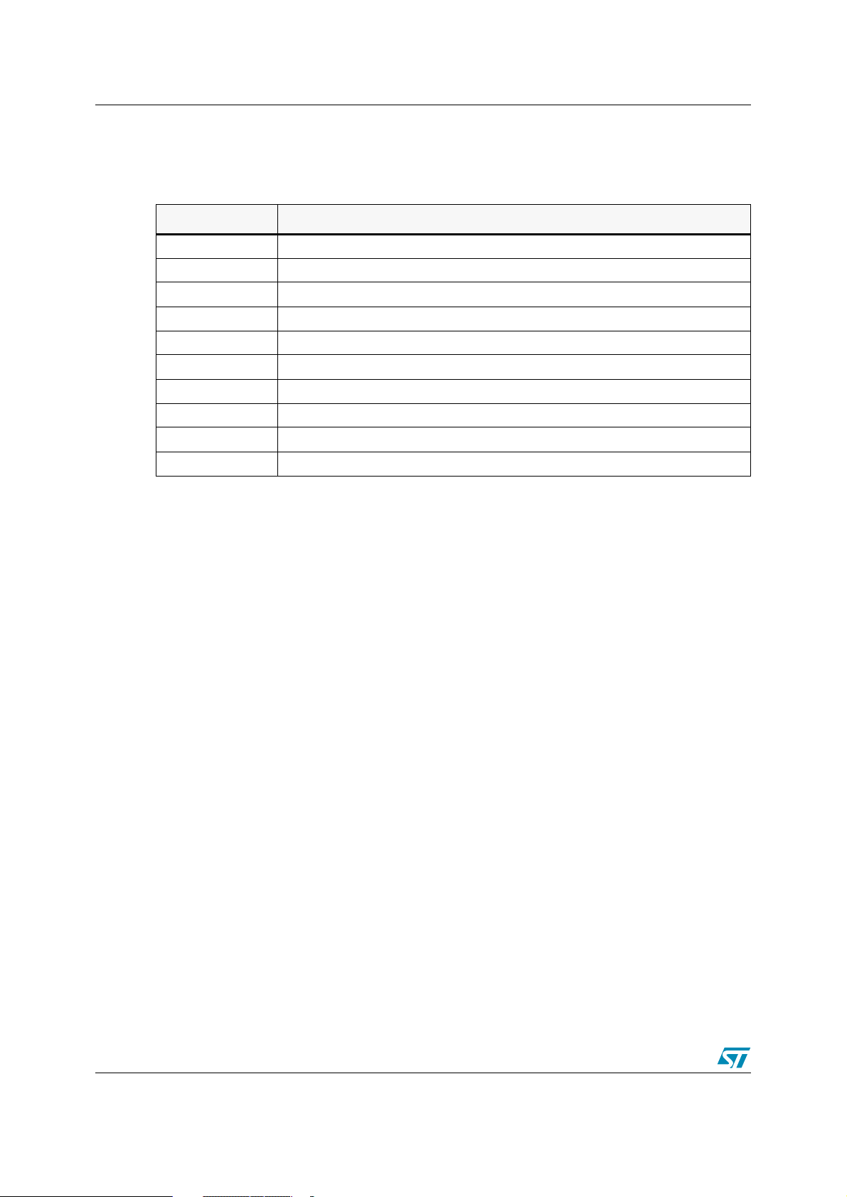
<format> specifies the output format. Output format options are listed in
Ta bl e 1 4
.
Table 14. Output formats
<format>
<none>
i
i32
ix
s
x
2
4
f
g
straight binary, i.e., a bit for bit image
Intel Hex
Intel Hex with 32-byte data per line
Intel Hex extended
Motorola S-record (1 byte per address, e.g. ST7)
Motorola S-record extended with symbol file
ST S-record 2 (2 bytes per address, e.g. D950)
ST S-record 4 (4 bytes per address, e.g. ST18932 program space)
'Filled' straight binary format
GP Industrial binary format
Output Format
5.2.4 Straight binary format
<format>= <none>
This is the simplest of the formats. It's nothing but a bit-for-bit copy of the original file. This the
usual mode for sending to the EPROM Emulators, etc., and is the default if no format argument
is given.
Note: When the destination is the screen (the destination code is "v"), don't use this format; otherwise you will only get weird
control codes.
<format>= <f>
This is the ‘filled’ straight binary format where gaps between adjacent segments are filled with
$FF.
5.2.5 Intel Hex format
<format>= i
This format is very much more complex. Intel Hex bears similarities to S-record that we'll be
looking at later. Let's look at a line of the Intel Hex format in detail:
:10190000FFFFFFFFFFC00064FFC0006462856285E0
10 number of data bytes (16 in decimal)
1900 address
00 record type
... data bytes
E0 checksum
42/92 UM0144
Page 43
ST7 Assembler Linker 5 OBSEND
The first thing to note is that every thing is in printable ASCII. Eight bit numbers are converted
into two-characters hexadecimal representation.
Each line begins with an ASCII ':' ($3A) character.
The next two characters form a byte that declares how many data bytes follow in the data byte
section little further along. The next four characters form a 16-bit high-byte first number that
specifies the address for the first byte of this data; the rest follows on sequentially.
The next two characters are the record type for this line: 00 is a data line, and 01 signals EOF.
The following characters until the last two are up the 16 data bytes for this line and, the last two
are a checksum for the line, calculated by starting with $00 subtracting the real value of all
characters sent after the ':' until the checksum itself. 'Real value' means that for example, the
two characters 3 and 0 should subtract $30 from the checksum, not 51 and 48. Every line ends
with a CR-LF combination, $0A and $0D.
The last line sent must be an END-OF-FILE line, which is denoted by a line with no data bytes
and a record type of 01 instead of 00.
Giving I32 or i32 instead of intel as the argument uses the same format, but sends 32 bytes of
data per line.
5.2.6 Motorola S-record format
<format>= s
This is another complex method for sending data. Again it cuts the data into 16-byte 'records'
with overhead either sides. S-record come in four types: S0, known as a header record, S1 and
S2 data records with 16 and 24-bit address fields, and S9and S8 EOF records with 16 and 24bit address fields.
Note: The convention is to close a S1 16-bit data record with the S9 16-bit EOF record, and to close a S2 24-bit data record
with the S8 24-bit EOF record.
S10D0010E0006285E000628562856D
S1 record type
0D number of bytes left, address, data and
checksum (13 in decimal)
0010 address
.... data bytes
6D checksum
The first two characters define the record type: S0, S1, S2, S8 or S9.
The next two characters form a hexadecimal representation of the numbers of bytes left in the
record (i.e., numbers of characters /2) This count must include the checksum and addresses
bytes that follow. The address field is four characters wide in S0, S1, S9 and six characters
wide in S2 and S8. The most significant character always comes first.
OBSEND will always use S1 type records wherever possible (i.e., when the address is less
than $10000) and use S2 type data records where it has to (i.e., address > $FFFF).
Up to 16 data bytes then follow, with the checksum appended on the end. The checksum is
calculated by starting with $FF and subtracting the 'real value' of all bytes sent from and
UM0144 43/92
Page 44

5 OBSEND ST7 Assembler Linker
including the byte count field until the checksum itself. In this context, 'real value' means the
value of the byte before it is expanded into two ASCII characters.
The record is concluded by a CR-LF combination $0A, $0D. The S0, S8 and S9 (i.e., header
and EOF) records are always the same:
S00600004844521B
and:
S804000000FB
S9030000FC
a complete example of S-record transmission may look like:
S00600004844521B
S113001AFF120094FF130094D08AFF390094FF1250
S20801C004FFC0000073
<format>= x
The extended S-record format, selected by format x, sends code as described above, except
that after the S9, it sends a list of SX records, one after the other, in the format:
SX 0000 LABEL
where 0000 are four ASCII zeroes, and LABEL is five ASCII characters. There are two spaces
after the SX and one space after the 0000. 0000 represents the hexadecimal value of the label.
LABEL may extend to 31 characters, and end with a carriage return.
5.2.7 ST 2 and ST 4 S-record formats
<format>= 2
<format>= 4
These are industrial formats defined for specific needs.
2: This format allows to specify 2-byte words for one address.
4: This format allows to specify 4-byte words for one address.
5.2.8 GP binary
<format>= g
This format is simple. It has a 16-byte count at the beginning low-byte first, calculated by
starting at 0, and adding the value of each byte until the end of the data is reached. If there are
any 'gaps' in your code, obsend will fill them in with $FF, and adjust the checksum accordingly.
After that four bytes of header information, the data follows in one big block.
44/92 UM0144
Page 45
ST7 Assembler Linker 6 Librarian
6 Librarian
6.1 Overview
If you do a lot of work on similar boards especially those with the same processor, it makes a great deal of
sense to reuse lumps of code you've already written to do the same task in a different program. At the
simplest level, you could just copy the source code as a block of text into the new program. This works
fine, but has a subtle disadvantage: if you update the subroutine, you have to hunt around all the usages
of it, performing the update on each.
To get around this problem, many people have the source for common routines in one place, and link the
.OBJ module with each program needing routine. Then you only need to update the source code once,
reassemble it to get a new .OBJ file, then link again all the users of the routine, who will now have the new
.OBJ file.
While this scheme works well, it generates some problems of its own. For example, each routine needs its
own .OBJ file. By nature, these common routines tend to be small, so you end up giving dozens of extra
.OBJ modules to the linker, and having the .OBJ modules scattered around your hard disk.
The base concept of a librarian is to combine all these small, useful .OBJ modules into one large .LIB
library file. You could then tell the linker about the library, and it would take care of sorting out which .OBJ
modules to pull into link. It would know which ones to pull by the fact that the main code being linked would
have undefined externals, for example, to call the missing library routines. The librarian simply takes each
undefined external in turn, and checks it against all the modules in the library. If any of the modules
declares a PUBLIC of the same name, it knows you need that .OBJ module and it includes it
automatically.
6.2 Invoking the librarian
The librarian is called LIB, and takes one command line argument that is the name of the library to
operate on. If not given, you'll be prompted for it.
LIB [library name]
.LIB is added if the suffix is left off.
If the library you indicate doesn't exist, LIB asks you if it's a new library.
For example:
LIB LIB1
STMicroelectronics - Librarian - rel 1.00
Couldn't open Library file 'LIB1.LIB'
is it a new file? (y/n): y
If the answer is 'n', LIB aborts. If the library exists, LIB prints up a report on the library.
Library LIB1.LIB is 2K long.
16/1024 Public labels used in 2/128 modules.
Next you're faced with the main prompt:
LIB1.LIB: Operation (<ENTER> for help):
UM0144 45/92
Page 46
6 Librarian ST7 Assembler Linker
Pressing ENTER gives you access to the options shown in
Table 15. Library file options
Operation Description
+filename
-filename
!filename
*filename copy object module to separate file from library
? list contents of library
x Exit to DOS
add/update object module to/in library
delete object module from library
update object module in library
6.3 Adding modules to a library
Typing for example:
+user1\board
would look for a file, called user1\board.obj, and add it to the library.
If LIB can't find the named file, LIB reports the fact and returns to the operations prompt. Else LIB issues
the following message:
Table 15
.
Adding new board.obj ...
15 labels added
Done.
If the library already contained a file board.obj, it would prompt you with:
board.obj already in library LIB1.LIB,
replace with board.obj (Y/N):
Responding with 'N’ returns you to the operations prompt, while 'Y' first removes the old board.obj then
continues as above.
6.4 Deleting modules from a library
This is done by, for example:
-board
If LIB cannot find board.obj in the current library, it reports an error and aborts back to the operation
prompt. If it can find it, it makes sure you know what you are doing with:
board.obj to be deleted from library LIB1.LIB: Are you sure (Y/N):
N’ aborts to operation prompt. 'Y' continues, reporting:
Removing old board.obj ...
Done.
46/92 UM0144
Page 47
ST7 Assembler Linker 6 Librarian
6.5 Copying modules from a library
To make a copy of a .OBJ module located in a library back to your hard disk, use, for example:
*board
This will check the existence of board.obj in the current library, if not it'll report the failure and abort the
operation prompt. If it does find it, it invites you to give it the name of the hard disk file to create to contain
the copy of the .OBJ module.
Copy into .obj file [board.obj]:
if you type <ENTER>, it'll select the original name of the object module as the copy's name. Otherwise, give
it a path spec. If the file you give already exists, LIB says:
File board.obj already exists; overwrite? (Y/N):
Again, responding 'N' aborts to the operations prompt, while 'Y' does the copy with the message:
Copying board.obj to disk...
Done.
6.6 Getting details in your library
The last operation:
?
causes LIB to print out details on the current library.
Library LIB1.LIB is 2K long
16/1024 Publics labels used on 2/128 modules
0: z1.obj (z1.asm) length 2DE
1: board.obj (board.asm) length 7FFF
The name in brackets is the source module from which the named object module was assembled.
UM0144 47/92
Page 48
ST7 Assembler Linker
Appendix A Assembler Directives
A.1 Introduction
Each directive has been given a new section to itself, and an entry in the index. The name of the directive,
which will always appear in the second field is given in the heading at the top of the section.
Next there is a line showing arguments allowed (if any) for this directive. The penultimate section
describes the action of the directive and the format and nature of the argument specified in the previous
section, and the last section gives one or more example of the directive in use.
There is a 'see also' cross reference at the bottom of the page.
All the directives must be placed in the second, OPCODE, field, with any arguments one tab away in the
argument field.
A.2 .BELL
Purpose: Ring bell on console.
Format: .BELL
Description: This directive simply rings the bell at the console; it can be used to signal the
end of pass-1 or pass-2 with #IF1 or #IF2. This directive does not generate
assembly code or data.
Example: .BELL
See Also:
48/92 UM0144
Page 49
ST7 Assembler Linker
A.3 BYTE
Purpose: Define byte in object code.
Format: BYTE <exp or “string”>,[,<exp or “string”>...]
Description: This directive forces the byte(s) in its argument list into the object code at the
current address. The argument may be composed of complex expressions,
which may even include external labels. If the argument was an expression and
had a value greater than 255 then the lower 8 bits of the expression are used
and no errors are generated. String argument(s) must be surrounded by double
quotes: theses are translated into ASCII and processed byte by byte. It's
generally used for defining data tables. Synonymous with STRING and DC.B.
Example:
See Also: DC.B, STRING, WORD, LONG, DC.W, DC.L
A.4 BYTES
Purpose: Label type definition where type = byte.
Format: BYTES
Description: When a label is defined, 4 separate attributes are defined with it: scope (internally
BYTE 1,2,3 ; generates 01,02,03
BYTE “HELLO” ; generates 48,45,4C,4C,4F
BYTE “HELLO”,0 ; generates 48,45,4C,4C,4F,0
0
or externally defined), value (actual numerical value of the label), relativity (absolute or relative), and length, (BYTE, WORD and LONG).
All of these attributes, except length, are defined explicitly before or at the definition. You can force the label to be a certain length by giving a dot suffix—eg.
'label.b' forces it to be byte length.
You may also define a default state for label length: labels are created to this length
unless otherwise forced with a suffix. The default is set to WORD at the start of the
assembly, but may be changed by BYTES, WORDS or LONGS to the appropriate
length.
Example:
lab1 EQU 5 ; byte length for lab1
See Also: LONGS, WORDS
BYTES
UM0144 49/92
Page 50
ST7 Assembler Linker
A.5 CEQU
Purpose: Equate pre-existing label to expression.
Format: label CEQU <exp>
Description: This directive is similar to EQU, but allows to change the label's value. Used in
macros and as counter for REPEAT / UNTIL.
Example:
See Also: EQU, REPEAT, UNTIL
A.6 .CTRL
Purpose: Send control codes to the printer.
Format: .CTRL <ctrl>[,<ctrl>]...
Description: This directive is used to send printing and non printing control codes to the selected
Example:
See Also: .LIST, .NOLIST, .BELL
A.7 DATE
lab1 CEQU {lab1+1} ; inc lab1
listing device. It's intended for sending control codes to embolden or underline, etc.
areas of listing on a printer. The arguments are sent to the listing device if the listing
is currently selected. This directive does not generate assembly code or data.
.CTRL 27,18
Purpose: Define 12-byte ASCII date into object code.
Format: DATE
Description: This directive leaves a message for the linker to place the date of the link in a 12-byte
block the assembler leaves spare at the position of the DATE directive. This means
that every link will leave its date in the object code, allowing automatic version control. The date takes the form (in ASCII) DD_MMM_YYYY where character '_' represents a space; for example 18 JUL. 1988. The date is left for the linker to fill instead
of the assembler since the source code module containing the DATE directive may
not be reassembled after every editing session and it would be possible to lose track.
Example:
See Also:
50/92 UM0144
DATE
Page 51
ST7 Assembler Linker
A.8 DC.B
Purpose: Define byte(s) in object code.
Format: DC.B <exp or "string">,[,<exp or "string">]
Description: This directive forces the byte(s) in its argument list into the object code at the cur-
rent address. The argument may be composed of complex expressions, which may
even include external labels. If the argument was an expression and had a value
greater than 255 then the lower 8 bits of the expression are used and no errors are
generated. String argument(s) must be surrounded by double-quotes: these are
translated into ASCII and processed byte by byte.
It's generally used for defining data tables. Synonymous with BYTE and STRING.
Example:
A.9 DC.W
Purpose: Define word(s) in object code.
Format: DC.W<exp>[, <exp>...]
Description: This directive forces the word(s) in its argument list into the object code at the current
Example:
See Also: DC.B, BYTE, STRING, WORD, LONG, DC.L
DC.B 1,2,3 ; generates 01,02,03
DC.B “HELLO” ; generates 48,45,4C,4C,4F
DC.B “HELLO”,0 ; generates 48,45,4C,4C,4F,00
address. The arguments may be composed of complex expressions, which may
even include external labels. If the argument was an expression and had a value
greater than FFFF then the lower 16 bits of the expression are used and no errors
are generated. DC.W sends the words with the most significant byte first.
It's generally used for defining data tables. Synonymous with WORD, except that
DC.W places the words in High / Low order.
DC.W 1,2,3,4,$1234 ;0001,0002,0003,0004,1234
UM0144 51/92
Page 52
ST7 Assembler Linker
A.10 DC.L
Purpose: Define long word(s) in object code.
Format: DC.L <exp>[,<exp>...]
Description: This directive forces the long word(s) argument list into the object code at the current
address. The arguments may be composed of complex expressions, which may
even include external labels. If the argument was an expression and had a value
greater than FFFFFFFF then the 32 bits of the expression are used and no errors
are generated. DC.L sends the words with the most significant byte first.
It's generally used for defining data tables. Synonymous with LONG, except that
DC.L stores the long-words in High / Low order.
Example:
See Also: DC.B, DC.W, BYTE, STRING, WORD, LONG
A.11 #DEFINE
Purpose: Define manifest constant.
Format: #DEFINE <CONSTANT ID> <real characters>
Description: The benefits of using labels in assembler level programming are obvious and well
DC.L 1,$12345678 ; 0000,0001,1234,5678
LONG 1,$12345678 ; 0100,0000,7856,3421
known. Sometimes, though, values other than the straight numerics allowed in labels
are used repeatedly in programs and are ideal candidates for special labelling.
The #DEFINE directive allows you to define special labels called 'manifest constants'. These are basically labels that contain strings instead of numeric constants.
During the assembly, wherever a manifest ID is found in the source code, it is
replaced by its real argument before the assembly proceeds. The #DEFINE is not
the definition of a label, so a space must precede the declaration.
The number of defines that the Assembler can manage is limited to 4096. However,
this depends on the number of characters in the statements. Depending on their
length, you may reach this limit sooner.
Example:
See Also:
52/92 UM0144
#define value 5
ld a,#value ; ld a,#5
Page 53
ST7 Assembler Linker
A.12 DS.B
Purpose: Define byte space in object code.
Format: DS.B [optional number of bytes]
Description: This directive is used to 'space out' label definitions. For example let's say we need a
set of byte-sized temporary storage locations to be defined in RAM, starting at
address $4000. We could write:
segment byte at 4000 'RAM'
temp1 equ $4000
temp2 equ $4001
which would work fine, however, we recommend you to write:
segment byte at 4000 'RAM'
temp1 DS.B
temp2 DS.B
which does the same job. The advantage is that the PC increments automatically.
There are two other types of DS instructions available for doing WORD and LONG
length storage areas: DS.W and DS.L. Note that the areas in question are not initialized to any value; it's merely a way of allocating values to labels.
The optional argument specifies how many bytes to allocate; the default is 1.
Because no code is generated to fill the space, you are not allowed to use DS.B in
segments containing code, only for segments with data definitions.
Example:
See Also: DS.W, DS.L
labl DS.B
UM0144 53/92
Page 54
ST7 Assembler Linker
A.13 DS.W
Purpose: Define word space in object code.
Format: DS.W [optional number of words]
Description: This directive is used to 'space out' label definitions. For example let's say we need a
set of word-sized temporary storage locations to be defined in RAM, starting at
address $4000. We could write:
segment byte at 4000 'RAM'
temp1 equ $4000
temp2 equ $4002
which would work fine, however, we recommend you to write:
segment byte at 4000 'RAM'
temp1 DS.W
temp2 DS.W
which does the same job. The advantage is that the PC increments automatically.
There are two other types of DS instructions available for doing BYTE and LONG
length storage areas: DS.B and DS.L. Note that the areas in question are not initialized to any value; it's merely a way of allocating values to labels.
The optional argument specifies how many bytes to allocate; the default is 1.
Because no code is generated to fill the space, you are not allowed to use DS.W in
segments containing code, only for segments with data definitions.
Example:
See Also: DS.B, DS.L
labl DS.W
54/92 UM0144
Page 55
ST7 Assembler Linker
A.14 DS.L
Purpose: Define long space in object code.
Format: DS.L [optional number of long words]
Description: This directive is used to 'space out' label definitions. For example let's say we need a
set of long-word-sized temporary storage locations to be defined in RAM, starting at
address $4000. We could write:
segment byte at 4000 'RAM'
temp1 equ $4000
temp2 equ $4004
which would work fine, however, we recommend you to write:
segment byte at 4000 'RAM'
temp1 DS.L
temp2 DS.L
which does the same job. The advantage is that the PC increments automatically.
There are two other types of DS instructions available for doing BYTE and WORD
length storage areas: DS.B and DS.W. Note that the areas in question are not initialized to any value; it's merely a way of allocating values to labels.
The optional argument specifies how many bytes to allocate; the default is 1.
Because no code is generated to fill the space, you are not allowed to use DS.L in
segments containing code, only for segments with data definitions.
Example:
See Also: DS.B, DS.W
A.15 END
Purpose: End of source code.
Format: END
Description: This directive marks the end of the assembly on the main source code file. If no END
Example:
See Also:
labl DS.L
directive is supplied in a source-code file then an illegal EOF error will be generated
by the assembler. Include files do not require an END directive.
END
UM0144 55/92
Page 56
ST7 Assembler Linker
A.16 EQU
Purpose: Equate the label to expression.
Format: label EQU <EXPRESSIONS>
Description: Most labels created in a program are attached to a source code line that generates
object code, and are used as a target for jumps or memory references. The rest are
labels used as 'constants', used for example, to hold the IO port number for the system keyboard: a number that will remain constant throughout the program.
The EQU directive allocates the value, segment type and length to the label field.
The value is derived from the result of the expression, the relativity (absolute or segment-relative derived from the most recent segment), the length is BYTE, WORD or
LONG, derived from the size default (starts off as WORD and may be changed by
directives BYTES, WORDS or LONGS).
Example:
See Also:
A.17 EXTERN
Purpose: Declare external labels.
Format: EXTERN
Description: When your program consists of several modules, some modules need to refer to
labl END 5
labels that are defined in other modules. Since the modules are assembled separately, it is not until the link stage that all the necessary label values are going to be
known.
Whenever a label appears in an EXTERN directive, a note is made for the linker to
resolve the reference.
Declaring a label external is a way of telling the assembler not to expect the label to
be defined in this module, although it will be used. Obviously, external labels must
be defined in other modules at link stage, so that all the gaps left by the assembler
can be filled with the right values.
Because the labels declared external are not actually defined, the assembler has no
way of knowing the length, i.e., (byte, word or long) of the label. Therefore, a suffix
must be used on each label in an EXTERN directive declaring its type; if the type is
undefined, the current default label scope (set by BYTES, WORDS, LONGS directives) is assumed.
Example:
See Also: PUBLIC
56/92 UM0144
EXTERN label.w, label1.b, label2.l
Page 57
ST7 Assembler Linker
A.18 #ELSE
Purpose: Conditional ELSE.
Format: #ELSE
Description: Forces execution of the statements until the next #ENDIF if the last #IF statement
was found false or disables execution of the statements until the next #ENDIF if the
last #IF statement was found true.
The #ELSE is optional in #IF / #ENDIF structures. In case of nested #ELSE state-
ments, a #ELSE refers to the last #IF.
Example:
See Also: #IF, #ENDIF
A.19 #ENDIF
Purpose: Conditional terminator.
Format: #ENDIF
Description: This is the non optional terminator of a #IF structure. If there is only one level of #IF
Example:
#IF {1 eq 0} ;
; block A ... not assembled
#ELSE
; block B ... assembled
#ENDIF
nesting in force, then the statements after this directive will never be ignored, no
matter what the result of the previous #IF was. In other words, the #ENDIF ends the
capability of the previous #IF to suppress assembly. When used in a nested situation
it does the same job, but if the last #IF / #ENDIF structure was in a block of source
suppressed by a previous #IF still in force, the whole of the last #IF / #ENDIF structure will be ignored no matter what the result of the previous #IF was.
#IF {count gt 0}
...
#ENDIF
See Also: #IF, #ELSE
UM0144 57/92
Page 58
ST7 Assembler Linker
A.20 FCS
Purpose: Form constant string.
Format: FCS <"string"> |<bytes> [<“string”> |<bytes>]...
Description: This directive works in the same way as the common STRING directive, except that
the last character in any string argument has bit 7 (e.g. MSB) forced high. Numeric
arguments in the same list are left untouched.
Example:
See Also: STRING
A.21 .FORM
Purpose: Set form length of the listing device.
Format: .FORM <exp>
Description: The assembler paginates the listing (when selected) with a default of 66 lines per
Example:
See Also: TITLE, SUBTTL, %OUT, .LALL, .XALL, .SALL, .LIST,.NOLIST
A.22 GROUP
FCS “ALLO” ; 41,4C,4C,CF
STRING “ALLO” ; 41,4C,4C,4F
page. This directive changes the page length from the default. This directive does
not generate assembly code or data.
.FORM 72
Purpose: Name area of source code.
Format: GROUP <exp>
Description: All source code following a GROUP directive until the next GROUP directive or the
end of the file - 'belongs' to the named group. Source code not included inside a
group is allocated to a special group called 'Default'.
Example:
See Also:
58/92 UM0144
GROUP mainloop
Page 59
ST7 Assembler Linker
A.23 #IF
Purpose: Start conditional assembly.
Format: #IF <exp>
Description: Sometimes it is necessary to have different versions of a program or macro. This
can be achieved by completely SEPARATE programs / macros, but this solution has
the associated problem that changes to any part of the program common to all the
versions requires all of them being changed, which can be tedious.
Conditional assembly offers the solution of controlled 'switching off' assembly of the
source code, depending on the value of the numeric expressions.
The structure is known as 'IF/ELSE/ENDIF': see the example for the format.
The #ELSE statement is optional. If the expression resolves to 0 the expression is
assumed to have a 'false' result: the source code between the false #IF and the next
#ENDIF (or #ELSE if supplied) will not be assembled.
If the #ELSE is supplied, the code following the #ELSE will be assembled only if the
condition is false.
Conditionals may be nested up to 15 levels: when nesting them, keep in mind
that each #IF must have a #ENDIF at its level, and that #ENDIFs and #ELSEs refer
to the last unterminated #IF.
Example:
See Also: #ENDIF, #ELSE, #IF1, #IF2
A.24 #IF1 Conditional
Purpose: Conditional on being in pass #1.
Format: #IF1
Description: This directive works just like #IF except it has no argument and only evaluates itself
as true if the assembler is on its first pass through the source code. Can use #ELSE
and requires #ENDIF.
Example:
See Also: #IF2, #ELSE, #IF, #ENDIF
#IF {1 eq 1}
%out true
#FALSE
%out false
#ENDIF
#IF1
%OUT “Starting Assembly”
#ENDIF
UM0144 59/92
Page 60
ST7 Assembler Linker
A.25 #IF2
Purpose: Conditional on being in pass #2.
Format: #IF2
Description: This directive works just like #IF except it has no argument and evaluates itself as
true only if the assembler is on its second pass through the source code.
Example:
See Also: #IF1, #IF, #ENDIF, #ELSE
A.26 #IFB
Purpose: Conditional on argument being blank.
Format: #IFB <arg>
Description: This directive works just like #IF except it doesn't evaluate its argument: it simply
Example:
#IF2
%OUT “GONE through PASS-1 OK”
#ENDIF
checks to see if it is empty or blank. Spaces count as blank.
check MACRO param1
#IFB param1
%OUT “No param1”
#ELSE
%OUT param1
#ENDIF
MEND
...
check ,
check 5
See Also: #IF2, #ELSE, #IF, #END
60/92 UM0144
Page 61
ST7 Assembler Linker
A.27 #IFIDN
Purpose: Conditional on arguments being identical.
Format: #IFIDN <arg-1> <arg-2>
Description: This directive works just like #IF except it compares two strings separated by a
space. If identical, the result is true.
Example:
See Also: #IF2, #ELSE, #IF, #END
A.28 #IFDEF
Purpose: Conditional on argument being defined.
Format: #IFDEF <exp>
Description: This directive works just like #IF except it tests for its argument being defined.
Example:
check MACRO param1
#IFIDN param1 HELLO
%OUT “Hello”
#ELSE
%OUT “No Hello”
#ENDIF
MEND
check MACRO param1
#IFDEF param1
%OUT “Arg is OK”
#ELSE
%OUT “Arg is undefined”
#ENDIF
MEND
See Also: #IF2, #ELSE, #IF, #END
UM0144 61/92
Page 62
ST7 Assembler Linker
A.29 #IFLAB
Purpose: Conditional on argument being a label.
Format: #IFLAB <arg>
Description: This directive works just like #IF except it tests that its argument is a valid, pre-
defined label.
Example:
See Also: #IF2, #ELSE, #IF, #END
A.30 #INCLUDE
Purpose: Insert external source code file.
Format: #INCLUDE “<filename>”
Description: INCLUDE files are source code files in the same format as normal modules but with
check MACRO param1
#IFLAB param1
%OUT “LABEL”
#ENDIF
MEND
two important differences: the first line usually reserved for the processor name is
like any other source line, and they have no END directive. They are used to contain
#DEFINE and macro definitions that may be used by many different modules in your
program.
Instead of having each module declare its own set of #DEFINE and macro definitions, each module just includes the contents of the same #INCLUDE file. The
assembler goes off to the named INCLUDE file and assembles this file before
returning to the line after the #INCLUDE directive in the former source code file.
The benefit is that any alterations made to a macro must be done once, in the
include file; but you'll still have to reassemble all modules referring to the changed
entry.
NOTE that the filename must be inside double-quotes.
Example:
See Also:
62/92 UM0144
st7/
#include “defst7.h”
...
END
Page 63
ST7 Assembler Linker
A.31 INTEL
Purpose: Force Intel-style radix specifier.
Format: INTEL
Description: The Intel style:
0ABh Hexadecimal
17o or 17q Octal
100b Binary
17 Decimal (default)
$ Current program counter
This directive forces the Intel format to be required during the assembly.
Example:
See Also: MOTOROLA, TEXAS, ZILOG
A.32 INTERRUPT
Purpose: Specifies to the debugger that a routine is an interrupt rather than a function.
Format: INTERRUPT <string>
Description: This directive is used with interrupt handlers and so aids the debugger in correctly
Example:
See Also: NEAR
A.33 .LALL
INTEL
ld X,0FFFFh
searching the stack for return address of the interrupted function.
PUBLIC trap_handler
INTERRUPT trap_handler
trap_handler IRET
Purpose: List whole body of macro calls.
Format: .LALL
Description: This directive forces the complete listing of a macro expansion each time a macro is
invoked. This is the default. This directive does not generate assembly code or data.
Example:
See Also: .XALL, .SALL
.LALL
UM0144 63/92
Page 64
ST7 Assembler Linker
A.34 .LIST
Purpose: Enable listing (default).
Format: .LIST
Description: This directive switches on the listing if a previous .NOLIST has disabled it. The -'pa'
or -'li' options must also have been set from the command line to generate a listing.
This directive, in conjunction with the directive .NOLIST, can be used to control the
listing of macro definitions. This directive does not generate assembly code or data.
Example:
See Also: .NOLIST
A.35 #LOAD
Purpose:
Format: #LOAD “pathname\filename[.ext]”
Description: This directive leaves a message for the linker to load the contents of the named file
Example:
See Also:
.LIST
Load named object file at link time.
at the current position in the current segment. The file should be in 'straight binary'
format, i.e., a direct image of the bytes you want in the object code. It should not be
in Motorola (.s19) or Intel (.hex) format.
segment byte at 8000-C000 'EPROM1'
#LOAD “table.bin”
64/92 UM0144
Page 65
ST7 Assembler Linker
A.36 LOCAL
Purpose: Define labels as local to macro.
Format: LOCAL <arg>
Description: A macro that generates loop code gives rise to an assembly problem since the loop
label would be defined as many times as the macro is called. The LOCAL directive
enables you to overcome this difficulty.
Consider the following piece of code:
waiter MACRO ads
loop ld A,ads
jrne loop
MEND
If this macro is called twice, you will be creating two labels called 'loop'. The answer
is to declare very early in the MACRO all labels created by the macro as LOCAL.
This has the effect of replacing the actual name of a local label (here 'loop') with
LOCXXXX where XXXX starts from 0 and increments each time a local label is
used. This provides each occurrence of the labels created inside the macro with a
unique identity.
Example:
See Also: MACRO, MEND
A.37 LONG
Purpose: Define long word in object code.
Format: LONG <exp>[,<exp>...]
Description: This directive forces the long word(s) in its argument list into the object code at the
Example:
waiter MACRO ads
LOCAL loop
loop led Aids
drone loop
MEND
current address. The arguments may be composed of complex expressions, which
may even include external labels. If the argument was an expression and had a
value greater than FFFFFFFF then the 32 bits of the expression are used and no
errors are generated. LONG sends long words with the least significant byte first.
It's generally used for defining data tables. Synonymous with DC.L, except that
LONG sends the low-byte first.
DC.L 1,$12345678 ; 0000,0001,1234,5678
LONG 1,$12345678 ; 0100,0000,7856,3421
See Also: DC.B, DC.L, DC.W, BYTE, STRING, WORD
UM0144 65/92
Page 66
ST7 Assembler Linker
A.38 LONGS
Purpose: Default new label length long.
Format: LONGS
Description: When a label is defined, four SEPARATE attributes are defined with it: scope (inter-
nally or externally defined), value (actual numerical value of the label), relativity
(absolute or relative), and lastly, length (BYTE, WORD or LONG).
All these attributes except length are defined explicitly before or at the end of the
definition: you can force a label to be a certain length by giving a dot suffix, e.g.
'label.b' forces it to be byte length.
You may also define a default state for label length: labels are created to this length
unless otherwise forced with a suffix. The default is set to WORD at the start of the
assembly, but may be changed by BYTES, WORDS or LONGS to the appropriate
length.
Example:
See Also: BYTES, WORDS
A.39 MACRO
Purpose: Define macro template.
Format: <macro> MACRO [param-1][,param-2]...
Description: This directive defines a macro template that can be invoked later in the program.
Example:
LONGS
lab1 EQU 5 ; long length for lab1
The label field holds the name of the macro: this name is used to invoke the rest of
the macro whenever it is found in the opcode field. The arguments are dummy
names for parameters that will be passed to the macro when it is used: these
dummy names will be replaced by the actual calling line's arguments.
Note: If you don't want the definition of the macro to be listed, insert directive
.NOLIST before the macro definition, and append directive .LIST after the macro
definition.
cmp16 MACRO first,second,result
LOCAL trylow
ld A,first
add A,second
cp A,#0
jreq trylow
cpl A
trylow ld result,A
MEND
See Also: MEND, .LALL, .SALL, .XAL
66/92 UM0144
Page 67
ST7 Assembler Linker
A.40 MEND
Purpose: End of macro definition.
Format: MEND
Description: End of macro definition.
Example:
See Also: MACRO
A.41 MOTOROLA
Purpose: Force Motorola-style radix specifier.
Format: MOTOROLA
Description: The Motorola style:
cmp16 MACRO first,second,result
LOCAL trylow
ld A,first
add A,second
cp A,#0
jreq trylow
cpl A
trylow ld result,A
MEND
$AB Hexadecimal
~17 Octal
%100 Binary
17 Decimal (default)
* Current program counter
This directive forces the Motorola format to be required during the assembly. The
default format is MOTOROLA.
Example:
See Also: INTEL, TEXAS, ZILOG
MOTOROLA
ld X,$FFFF
UM0144 67/92
Page 68
ST7 Assembler Linker
A.42 NEAR
Purpose: Specifies to debuggers that the return address in the stack for functions using this
directive is written over two bytes.
Format: NEAR <"string">
Description: This directive is used with functions called by CALL or CALLR, whose return stack
address spans two bytes. Every function called by CALL or CALLR must be classified as NEAR.
Example:
See Also: INTERRUPT
A.43 .NOCHANGE
Purpose: List original #define strings.
Format: .NOCHANGE
Description: Strings named in the first argument of a #DEFINE directive will be changed to the
Example:
See Also: #DEFINE
PUBLIC func
NEAR func
func ret
second argument of the #DEFINE: the default is that the changed strings will be
listed. If you want the original source code to be listed instead, place a .NOCHANGE
directive near the start of your source code. This directive does not generate assembly code or data.
.NOCHANGE
A.44 .NOLIST
Purpose: Turn off listing.
Format: .NOLIST
Description: Certain parts of your modules may not be required on a listing; this directive disables
the listing until the next .LIST directive. The default is for the listing to be enabled.
This directive, in conjunction with the directive .LIST, can be used to control the list-
ing of macro definitions. This directive does not generate assembly code or data.
Example:
See Also: LIST
68/92 UM0144
.NOLIST
Page 69
ST7 Assembler Linker
A.45 %OUT
Purpose: Output string to the console.
Format: %OUT string
Description: This directive prints its argument (which does not need to be enclosed in quotes) to
the console. This directive does not generate assembly code or data.
Example:
See Also:
A.46 .PAGE
Purpose: Perform a form feed.
Format: .PAGE
Description: Forces a new page listing. This directive does not generate assembly code or data.
Example:
See Also:
A.47 PUBLIC
Purpose: Make labels public.
%OUT hello!
.PAGE
Format: PUBLIC <arg>
Description: This directive marks out given labels defined during an assembly as 'PUBLIC', i.e.,
accessible by other modules. This directive is related to EXTERN; if one module
wants to use a label defined in another, then the other module must have that label
declared PUBLIC.
A label may also be declared PUBLIC as its definition by preceding the label name
with a dot; it won't need to be declared in a PUBLIC directive then.
Example:
See Also: EXTERN
module1.asm
EXTERN print.w, print1.w
...
call print
...
jp print1
module2.asm
PUBLIC print
print nop
.print1 nop
UM0144 69/92
Page 70
ST7 Assembler Linker
A.48 REPEAT
Purpose: Assembly-time loop initiator.
Format: REPEAT
Description: Used together with UNTIL to make assembly-time loops; it is useful for making
tables etc. This directive should not be used within macros.
Example:
See Also: CEQU, UNTIL
A.49 .SALL
Purpose: Suppress all body of called macro.
Format: .SALL
Description: This directive forces the complete suppression of the listing of a macro expansion
Example:
See Also: .LALL, .XALL
REPEAT
each time a macro is invoked. This instruction is never listed.
Note:This directive may produce confusing listings.
.SALL
70/92 UM0144
Page 71

ST7 Assembler Linker
A.50 SEGMENT
Purpose: Start of new segment.
Format: [<name>] SEGMENT <align> <combine> '<class>' [cod]
Description: The SEGMENT directive is very important: every module in your program will need at
least one.
The <name> field may be up to 11 characters in length, and may include underscores. The <align> field is one of the following:
Align Type: byte no alignment; can start on any byte boundaries
word aligned to next word boundaries if necessary, i.e., 8001=8002
para aligned to the next paragraph (=16 bytes) boundary, i.e., 8001=8010
64 aligned to the next 64-byte boundary, i.e., 8001=8040
128 aligned to the next 128-byte boundary, i.e., 8001=8080
page aligned to the next page (=256 bytes) boundary, i.e., 8001=8100
long aligned to the next long-word(=4 bytes) boundary, i.e., 8001=8004
1K aligned to next 1K boundaries, i.e., 8001=8400
4K aligned to next 4K boundaries, i.e., 8001=9000
Combine: at X[-Y] Introduces new class that starts from X and goes through to address
Y. Address Y is optional.
<none> Tack this code on the end of the last segment of this class.
common Put the segment at the same address than other common segments
that have the same name, and note the longest length segment.
The optional [cod] suffix is a number from 0 to 9 - it decides into
which. COD file the linker sends the contents of this class. 0 is the default and is chosen if the suffix is left off. A suffix of 1-9 will cause the
linker to open the [cod] suffix, and send the contents of this class into
the cod file instead of the default. This allows bank switching to be
supported directly at link level- different code areas at the same address can be separated out into different .cod files.
See Also: For more information, see
UM0144 71/92
Section 3.4
on page 22.
Page 72
ST7 Assembler Linker
A.51 .SETDP
Purpose: Set base address for direct page.
Format: .SETDP <base address>
Description: If you have used an ST7 processor, you'll be aware of its 'zero-page' or 'direct'
addressing modes. These use addresses in the range 00..FF in shorter, faster
instructions than the more general 0000..FFFF versions. Other processors use the
same scheme, but with a twist: you can choose the 'base page' where the direct
mode does not have to be in range 0000 00FF but can be from nn00..nnFF where
nn00 is the 'base page', loaded into a register at run-time. Because the assembler
cannot track what's in the base page register at run-time, you need to fill it in about
the current 'base page' with the .SETDP directive. At the start of the assembly,
SETDP defaults to 0000.
Example:
See Also:
A.52 SKIP
Purpose: Inserts given number of bytes with an initialization value.
Format: SKIP <number of bytes>,<value to fill>
Description: This directive leaves a message for the linker that you want X number of Y bytes to
Example:
See Also:
.SETDP $400
ld A,$401 ; direct mode chosen
be inserted into the object code at this point. Both the arguments must be absolute
values rather than external or relative values.
SKIP 100,$FF ; insert 100 bytes all $FF
72/92 UM0144
Page 73
ST7 Assembler Linker
A.53 STRING
Purpose: Define a byte-level string.
Format: STRING <exp or “string”>,[,<exp or “string”>...]
Description: This directive forces the byte(s) in its argument list into the object code at the current
address. The arguments may be composed of complex expressions, which may
even include external labels. If the argument was an expression and had a value
greater than 255 the lower 8 bits of the expression are used and no errors are generated. String argument(s) must be surrounded by double-quotes: these are translated
into ASCII and processed byte by byte. It's generally used for defining data tables.
Synonymous BYTE and DC.B.
Example:
See Also: DC.B, BYTE, WORD, LONG, DC.W, DC.L, FCS
A.54 SUBTTL
Purpose: Define a subtitle for listing heading.
Format: SUBTTL “<Subtitle string>”
Description: This directive is related to the TITLE directive: its argument is used as a subtitle at
Example:
See Also: TITLE
STRING 1,2,3 ; generates 01,02,03
STRING “HELLO” ; generates 48,45,4C,4C,4F
STRING “HELLO”,0 ; generates 48,45,4C,4C,4F,00
the beginning of each page on a listing. We recommend that individual subtitles are
generated for each module in a program, while the TITLE is defined once in the
include file called by all the modules. This directive does not generate assembly
code or data.
SUBTTL “A/D control routines”
UM0144 73/92
Page 74
ST7 Assembler Linker
A.55 .TAB
Purpose: Set listing field lengths.
Format: .TAB <label>,<Opcode>,<operand>,<comment>
Description: Sets the size of the four source code fields for listings. The defaults of 0, 8, 16, 24 are
for 80-column printer; if yours can go wider, you need to tell the assembler using this
directive. The four fields are the width of the label field, the opcode field, operand and
comment. This directive does not generate assembly code or data.
Example:
See Also: .LIST, .NOLIST
A.56 TEXAS
Purpose: Texas Instruments-style radix specifier.
Format: TEXAS
Description: The Motorola style:
Example:
.tab 10,6,16,40
>AB Hexadecimal
~17 Octal
?100 Binary
17 Decimal (default)
$ Current program counter
This directive forces the Texas Instruments format to be required during the assembly.
TEXAS
ld X,>FFFF
See Also: INTEL, MOTOROLA, ZILOG
74/92 UM0144
Page 75
ST7 Assembler Linker
A.57 TITLE
Purpose: Define main title for listing.
Format: TITLE “<Title string>”
Description: The first fifty-nine characters of the argument (which must be enclosed in double-
quotes) will be included on the first line of each page in a listing as the main title for
the listing. We suggest you set the title in the include file called by each module in
your program, and give each module a separate subtitle (see SUBTTL section). This
directive does not generate assembly code or data.
Example:
See Also: SUBTTL
A.58 UNTIL
Purpose: Assembly time loop terminator.
Format: UNTIL <exp>
Description: Related to REPEAT directive: if the expression in the argument resolves to a non
Example:
See Also: CEQU, REPEAT
TITLE “ST7 controller program”
zero value then the assembler returns to the line following the last REPEAT directive.
This directive cannot be used inside macros.
val CEQU 0
REPEAT
DC.L {10 mult val}
val CEQU {val+1}
UNTIL {val eq 50}
UM0144 75/92
Page 76
ST7 Assembler Linker
A.59 WORD
Purpose: Define word in object code.
Format: WORD <exp>[, <exp>...]
Description: This directive forces the word(s) in its argument list into the object code at the cur-
rent address. The arguments may be composed of complex expressions that may
even include external labels. If the argument was an expression and had a value
greater than FFFF then the lower 16 bits of the expression are used and no errors
are generated. WORD sends the words with the least significant byte first.
It's generally used for defining data tables. Synonymous with DC.W.
Example:
See Also: DC.B, BYTE, STRING, DC.W, LONG, DC.L
A.60 WORDS
Purpose: Default new label length word.
Format: WORDS
Description: When a label is defined, four SEPARATE attributes are defined with its scope (inter-
Example:
WORD 1,2,3,4,$1234 ;0001,0002,0003,0004,1234
nal or external defined) value (actual numerical value of the label) relativity (the label
is ABSOLUTE or RELATIVE), and lastly length (BYTE, WORD, or LONG).
All these attributes except length are defined explicitly before or at the definition: you
can force the label to be of a certain length by giving a dot suffix, e.g. 'label.b' forces
it to byte length.
You may also define a default state for label length: the label is created to this length
unless otherwise forced with a suffix. The default is set to WORD at the start of the
assembly, but may be CHANGED by BYTES, WORDS or LONGS to the appropriate
length.
WORDS
lab1 EQU 5 ; word length for lab1
See Also: BYTES, WORDS
76/92 UM0144
Page 77
ST7 Assembler Linker
A.61 .XALL
Purpose: List only code producing macro lines.
Format: .XALL
Description: This directive forces a reduced listing of a macro expansion each time a macro is in-
voked. Only those lines of the macro that generated object code are listed. This instruction itself is not listed. This directive does not generate assembly code or data.
Example:
See Also: .LALL,.SALL
A.62 ZILOG
Purpose: Force Zilog-style radix specifiers.
Format: ZILOG
Description: The Motorola style:
Example:
.XALL
%AB Hexadecimal
%(8)17 Octal
%(2)100 Binary
17 Decimal (default)
$ Current program counter
This directive forces the Zilog format to be required during the assembly.
ZILOG
ld X,%FFFF
See Also: INTEL, MOTOROLA, TEXAS
UM0144 77/92
Page 78
ST7 Assembler Linker
Appendix B Error Messages
B.1 Format of error messages
There are two classes of errors trapped by the assembler: fatal and recoverable.
A fatal error stops the assembly there and then, returning you to the caller (which may or may not be DOS;
CBE can also invoke the assembler) with a message and error number describing the problem.
The actual format of the error messages is as follows:
file.asm(line): as<pass> : Error <errno> : <message> '<text>'
For Example:
prog.asm(10): as2 : Error 50 : Doubly defined label 'fred'
error number
name of the program that handled the error
line number in the file
name of the file where the error was found
string describing the error
Note: The name of the program that handled the error (third field), can be as1 or as2 depending on
the pass in progress when the error was found.
The error number (fourth field) can be used as an index to find a more complete description of
the error in the next section (fatal errors read 'FATAL nn', instead of 'ERROR nn').
B.2 File CBE.ERR
Fatal and recoverable errors both are copied into the file CBE.ERR as they occur. CBE can use this
error file to give automatic error-finding. Most linker errors are also copied into CBE.ERR.
LINKER errors are described
page 84
.
B.3 Assembler errors
1 Empty file
The assembler couldn't read even the first line of the given source code file.
2 EOF while in Macro Definition
The file ended while a macro was being defined; you should end the last macro definition
properly with a MEND statement.
3 Couldn't return to old place in source file 'X.asm'
78/92 UM0144
Page 79
ST7 Assembler Linker
This error should never occur; it implies you have a disk fault of some kind. After a
#include, the assembler returns to the line after the #include itself. If it cannot return to that
line this error is produced.
4 Illegal Source EOF
Main source code files must end with an END directive and a carriage-return.
5 EOF before line terminator
The END directive must have at least one CR after it: for example <TAB> END <EOF> will
generate this error while <TAB> END <EOF> will work fine.
6 Code produced outside Segment
Any code produced by the assembler is going to have to be placed on a given address in
the target system at the end of the day. Since segments are the assemblers way of
allocating addresses to lumps of code, any code generated before the first SEGMENT
directive is nonsense.
^T 55 Move to top line of current window
^V 56 Move to last line of current window
^U 57 Undo changes to last edited line
^[ 58 Drop start of black marker
^] 59 Drop end of black marker
^F 60 Find Source Code for Hex address
^J 61 Report value of given label
^N 62 Report address of current Editor line
These functions mostly explain themselves; the Alternate functions do the same job as
the original functions of the same name: having two indexes for the same job allows
the cursor keys and control codes to move the cursor, whichever the user prefers. Some
indexes are not used by the default key sequence matrix; these allow some WordStar-like
commands to be implemented with more meaning.
Multiple-key sequences, such as those found in WordStar format control codes need to be
implemented as follows: take the sequence <^Y><L>, i.e., CTRL-Y followed by the letter L
should be coded as ^Y+L where the + denotes that the following character needs no CTRL
or SHIFT.
18 File capture Error
#Include had problems finding the named file.
19 Can't find position in Source File
Again to do with #include, another 'impossible' error reporting that it couldn't find the
current position of the source file to remember it for after the #include.
20 Can't have more than 4096 #defines
Each #define has to be checked for in each possible position in each source line: having
too many of them slows the assembly noticeably. Although you can have up to 4096
#defines, there are also limits on the storage space for both the arguments (error 23); an
average of eight characters for both arguments is recommended.
UM0144 79/92
Page 80
ST7 Assembler Linker
21 Run out of #define storage space (1)
See Error 20.
22 #define has no second argument
#define requires a space between the two parts of its argument to delimit it.
23 Run out of #define storage space (2)
See Errors 20 and 21 above; you've reached the limit of the storage space set aside for
the second argument of #defines.
24 No strings in DC.W
Strings are only allowed as parts of BYTE, DC.B or STRING directives.
25 No strings in DC.L
Strings are only allowed as parts of BYTE, DC.B or STRING directives.
26 Illegal External Suffix
Only the suffixes .b, .B, .w, .W, .l, .L are legal after an external label in an external
directive. If the suffix is left out then the default label size is used (as set by BYTES,
WORDS or LONGS; default is WORDS).
27 Bad Character in public line
28 More than four characters in single quotes
This assembler uses double-quotes to surround string items and single-quotes to
surround character constants. See
29 Uneven Single Quotes
Section 3.3
on page 13.
Single-quoted items must have a closing quote to delimit.
30 Sequential operator error
It does not allow arithmetic operators to be hard up against each other.
31 No lvalue in Expression.
An lvalue is the left-hand argument of an operator: a + b has 'a' as its lvalue. +b would
cause this error.
32 Divide by zero
Attempt to divide a number by zero, in a numeric expression.
33 Ifs nested past 15 levels
Exceeded maximum number of nested #IF statements.
34 Spurious ELSE
An ELSE was discovered when no active IF was in force.
35 Spurious ENDIF
An ENDIF was discovered when no active IF was in force.
36 Only allowed inside Macros
A LOCAL directive was attempted outside a Macro definition.
37 No strings in Word
See Error 24.
38 No string in Long
See Error 25.
80/92 UM0144
Page 81
ST7 Assembler Linker
39 No REPEAT for this UNTIL
An UNTIL directive is found with no matching REPEAT directive.
40 Couldn't return to old place in Source
Similar to Error 3 but generated by UNTIL instead of #include.
43 Syntax Error in SKIP arguments
SKIP expects two numeric arguments, separated by a comma.
44 First SKIP argument is extern/relative; SKIP aborted
SKIP arguments must be known to the assembler absolutely. Extern or relative arguments
are not allowed, although arithmetic is. If you need to move up to a new page, for example,
use a new SEGMENT of the same class with a page align type.
45 Second SKIP argument is extern/Relative; SKIP aborted
See Error 44.
46 Undefined label
This error happens when a reference is made to an undefined label.
47 Out of label space
A maximum of 1024 labels are allowed per module, and 10k is set aside to contain their
names. If either of these limits is exceeded, this error results. Cut the module into two
smaller ones; the assemblies will happen twice as fast and you'll only have to reassemble
the half you've made changes to, speeding things up.
48 Label more than 30 characters
Labels longer than 30 characters are not allowed.
49 Label defined as PUBLIC twice
This warning occurs if the same label appears more than once in a PUBLIC statement. It's
trapped because the second appearance may be a typographical error of a slightly
different label you wanted declared as public.
50 Doubly Defined label
This happens when a label is defined twice or more.
51 Phase Inconsistency (P1=X,P2=Y) 'label'
Reports that the named label was allocated different values from pass-1 and pass-2,
implies awful things. It's generally caused when for some reason the assembler has
generated different lengths for the same instruction between pass-1 and pass-2.
Sometimes if the assembler has problems identifying which addressing mode you wanted
for a particular instruction because of typographical errors, or labels that are discovered to
be undefined during the second pass it may give an error (see Error 54) and create no
object code for that line. All labels after that line will then be allocated different values
seeing as the object code is now that many bytes shorter, causing tons of Phase
Inconsistency errors. Because this mass of Error 51s can sometimes hide the real cause
of the error, a special assembler switch /np for 'no phase [errors]' can be used to switch
them off. We strongly suggest that you don't always use /np on all your assemblies; only
use it when you need it or you might miss critical phase errors.
52 Public Symbol Undefined
You defined a symbol in a PUBLIC directive that was not defined in the module.
53 Missing Hex Number
The assembler was led to expect a hex number but found one of zero length.
UM0144 81/92
Page 82
ST7 Assembler Linker
54 Can't match Addressing Mode
This error is a catchall for the assembler if it cannot see anything wrong with your line but
cannot match it to a known addressing mode either.
There are two main causes of errors: significant ordering and numeric range errors. The
significant ordering error is a simple typographical error: what should have been (val),y
was coded as (valy, or whatever. All the components of the addressing mode are properly
formed; it's just that the ordering is wrong. The numeric range errors can be harder to
detect. For example, an 8-bit relative branch branching out of range would be trapped as
an addressing mode error.
To aid diagnostics of what went wrong the assembler dumps out its model of the line to the
screen just before the error. Numerics are printed as a hex value followed by an attribute
string: INTernal, EXTernal, ABSolute, RELative and .b, .w, .l. Significands are printed as
the characters they represent, and strings are printed with their string.
Numeric range errors are also trapped at the link stage (See
55 Bad PSIG Index
Section 4.1
on page 35).
An 'impossible' error that could only occur through corruption of the .TAB file.
56 Un-recognized Opcode
The Opcode (second field) could not be matched against any opcode names for this
instruction set, nor could it be matched against any macro names or directives.
57 No closing quote
String must have closing double-quote before the end of the line.
58 No more than 12 Numerics allowed on one line
These's a limit of 12 Numeric units allowed on one line: this usually only matters on long
DC.B-type directives where data tables are being defined. If it's a problem, simply cut the
offending long line into two shorter lines.
59 Out of space for Macro Definition
The Macro Storage area (ca 64K) has been overflowed. You must have some really big
macros!
60 Too many Macros Attempted
There is a limit of 128 Macros allowed per source code module.
61 Mend only allowed in Macro
MEND directive found with no matching MACRO directive.
62 No closing single Quote
See error 29.
63 Bad Ending
Another 'impossible' error, saying that the CR on the end of a source code line was
missing.
64 Bad Character in line
As each source code line is read into the assembler it's checked for non-ASCII characters
(i.e., >128).
65 Parameter Mismatch
The macro definition implies that there is a different number of parameters than there
actually were in this calling line.
82/92 UM0144
Page 83
ST7 Assembler Linker
66 Currently Unknown Numeric type
An error in your Tabgen File, or a corrupted .TAB file: the numeric handler was asked to
check a number against an undefined numeric type. Are you using the latest version of
ASM.EXE and your .TAB file?
67 Improper Characters
Unusual characters have been spotted in the source file, of value >127.
68 Label used before its EXTERN definition
Labels must be declared EXTERNAL before their use, preferably in a group at the top of
the file.
69 Ambiguous Label Name
The label name in the single-quotes at the end of the error-line can be confused with a
register name in this instruction set. Change the name.
70 Cannot have DS.X in segments containing code/data! (only for [void] segs!)
DS.X does not produce any code; it simply advances the assembler's notional Program
Counter. It cannot be used in the same segment as real 'code' or data.
71 Cannot have code in segments previously containing DS.X (only for non-void segs!)
DS.X does not produce any code; it simply advances the assembler's notional Program
Counter. It cannot be used in the same segment as real 'code' or data.
72 Constant too large for directive 'value'
A DC.B cannot be given an argument >255, for example. Use LOW or OFFSET operators
to truncate any wild arguments.
73 Couldn't find entry for segment in mapfile
This is for listings produced with '-fi' option. Complex include file structures and empty
segments can sometimes throw the assembler off the track.
74 COD index only allowed on Introduction
When you're using the multiple linker output file scheme, you can only specify the linker
output file number for a particular class at the time of that class's introduction.
75 #LOAD before Segment!
The #load has to be but at a given address! Before the first segment the assembler won't
know what address to put it at! Shift the #load after a SEGMENT directive.
76 #LOAD before Segment!
The assembler had problems finding the file you've named in a #LOAD directive.
77 All EQUs Involving External args must be before first segment!
78 Cannot nest #includes > 5 levels
79 Couldn't find label list in mapfile
Happens with option '-fi' - Implies problem with the mapfile itself, or unsuccessful previous
link, etc.
80 Couldn't find label in mapfile
As above. Is the Mapfile up to date with your Edits? A label may be declared EXTERN, but
never used.
81 Couldn't find label in mapfile
The date info has to be stored at a given address - before a SEGMENT there is no
address information for the assembler to work on.
UM0144 83/92
Page 84
ST7 Assembler Linker
82 No string given on FCS line?
FCS is used for defining strings. Why is there no string on this line? Did you intend that? If
so, use DC.B or BYTE.
83 Address not on WORD boundary
For 68000 and certain other genuine 16-bit, Opcodes must be on word boundary. This
error occurs if you have assembled an instruction at an odd address. Your processor
would crash!
84 Byte size label has value >255 (need WORDS?)
85 Word size label has value > 65535 (need LONGS?)
86 Over 250 Macline Pull
Internal Error.
87 Run out of Source File
Internal Error.
88 TAB arguments incorrect
Must be in order num, num, num, num for example, TAB 8, 8, 12, 32.
89 Illegal suffix
An unknown suffix has been used with a label. Recognized suffixes are .b, .w and .l.
101 Label defined as NEAR and INTERRUPT
103 Label defined as NEAR twice
105 Label defined as INTERRUPT twice
B.4 Linker errors
The following is a list of linker error numbers and their definitions:
1 File List must be supplied
2, 3, 11, 13 Incomplete Object File
Fatal error - the linker has identified that the given object file has been truncated. How are
you for disk space?
4, 23 Size mismatch on EXTERN from F1 says .X, PUBLIC from F2 says .Y.
When declared PUBLIC in file F2 the label L was given size attribute Y. However, when
you came to use it in file F1, the EXTERN statement named L as being of size .X - they
didn't tally. They must. Find out which is incorrect and alter it.
5 No info on start address of class 'class'
The first time the linker sees a class (remember it goes through the object files in the order
given on the link command line), it must be given the full 'introduction' to the class, with
start and stop addresses. See
6 Too many secondary externals (32)
Secondary Externals ought to occur only rarely in your code - If you're using >32 then your
structure has something seriously wrong with it. Hint - all your labels that are used all over
the place, like constants, addresses of IO, and the like: make a module just for them, just
containing EQUs and/or DS.Xs, all declared public. Any arithmetic needs doing more than
Section 3.4
on page 22.
84/92 UM0144
Page 85
ST7 Assembler Linker
once throughout your code, do it there, and declare the result with its own public label.
Then refer to these PUBLICs using simple EXTERNs in each module.
7, 19 Corrupted Object File
Disk Nastiness. Reassemble. There may be an object code inconsistency: re-assemble all
the files, and link again.
8 Public of same name as secondary EXTERN already exists!
This error cannot be seen until link time. Rename one or the other.
9 To many XREFs to link (12048)
10 Undefined EXTERN L (from F1)
12 Couldn't seek back in file 'F1'
Internal Error. Should never occur.
14 Unexpected 7f
Disk nastiness. Reassemble.
15 Byte size exp >Offh 'value'
Needs looking at. If it is what you intended, either use the LOW operator to saw off upper
bits, or change the size attribute.
UM0144 85/92
Page 86
ST7 Assembler Linker
Appendix C Revision History
Date Revision Description of changes
1-Jul-2001 1 • Initial release
30-Jun-2005 2 • Updated
• Updated
• Added
Revision History
Introduction
Getting Started
installation procedure
86/92 UM0144
Page 87
ST7 Assembler Linker
Appendix D Product Support
If you experience any problems with this product, or contact the distributor or the
STMicroelectronics sales office where you purchased the product. Phone numbers for major
sales regions are provided in the
In addition, at our Internet site www.st.com/mcu, you will find a complete listing of ST sales
offices and distributors, as well as documentation, software downloads and user discussion
groups to help you answer questions and stay up to date with our latest product developments.
D.1 Software updates
3. All our latest software and related documentation are available for download from the ST
Internet site, www.st.com/mcu.
Contact List
Contact List
North America
, below.
Canada and East Coast
STMicroelectronics
Lexington Corporate Center
10 Maguire Road, Building 1, 3rd floor
Lexington, MA 02421
Phone: (781) 402-2650
West coast
STMicroelectronics, Inc.
1060 E. Brokaw Road
San Jose, CA 95131
Phone: (408) 452-8585
Mid West
STMicroelectronics
1300 East Woodfield Road, Suite 410
Schaumburg, IL 60173
Phone: (847) 585-3000
Note: For American and Canadian customers seeking technical support the US/Canada
is split in 3 territories. According to your area, contact the appropriate sales office
from the list above and ask to be transferred to an 8-bit microcontroller Field
Applications Engineer.
Europe
France +33 (0)1 47 40 75 75
Germany +49 89 46 00 60
U.K. +44 162 889 0800
Asia/Pacific Region
Japan +81 3 3280 4120
Hong-Kong +85 2 2861 5700
Shanghai +86 21 52574828
Sydney +61 2 9580 3811
Taip ei +88 6 2 2378 8088
UM0144 87/92
Page 88

ST7 Assembler Linker
Index
Symbols
.asm ....................................................................................13
.cod .....................................................................3, 25, 35, 41
.fin ...................................................................................3, 41
.lib........................................................................................ 45
.map ....................................................................................38
.obj ..................................................................................3, 35
.rsp ......................................................................................36
.s19 .....................................................................................41
.sym..................................................................................... 38
.tab ......................................................................................13
/np assembler switch........................................................... 81
‘@’ sign (linker) ...................................................................36
’&’ character ........................................................................28
’.’ in labels ...........................................................................17
Numerics
128-byte boundary .............................................................. 24
16-byte boundary ................................................................ 24
1k-byte boundary ................................................................ 24
256-byte boundary .............................................................. 24
30 characters ......................................................................81
4-byte boundary .................................................................. 24
4K-byte boundary................................................................ 24
64-byte boundary ................................................................ 24
80-column printer................................................................74
A
address representation .......................................................17
align
128 .............................................................................. 71
1K.......................................................................... 24, 71
4K.......................................................................... 24, 71
64 .......................................................................... 24, 71
byte .......................................................................24, 71
long .......................................................................24, 71
page ......................................................................24, 71
para....................................................................... 24, 71
word ......................................................................24, 71
Align argument in segments................................................ 23
ampersand (’&’) character................................................... 28
asli.bat...................................................................................4
ASM ....................................................................................30
assembler options
-d.................................................................................31
-fi .................................................................................31
-i ..................................................................................31
-li .................................................................................31
-li= ............................................................................... 31
-m................................................................................31
-np...............................................................................31
-obj .............................................................................. 31
-pa...............................................................................31
-sym ............................................................................ 31
attributes
byte ............................................................................. 14
externally..................................................................... 14
internally...................................................................... 14
linker relative or absolute............................................14
long ............................................................................. 14
relativity.................................................................14, 15
scope..................................................................... 14, 16
size..............................................................................14
word ............................................................................ 14
C
cbe.err...........................................................................13, 78
class-names........................................................................23
combine
at ........................................................................... 24, 71
common ................................................................24, 71
Combine argument in a segment........................................24
comments............................................................................21
conditional assembly........................................................... 29
conditionals (nesting) .......................................................... 59
constants............................................................................. 18
copied code......................................................................... 26
cross-references ...................................................................3
D
directives
#DEFINE..................................................................... 52
#ELSE.........................................................................57
#ENDIF ....................................................................... 57
#IF...............................................................................59
#IF1.............................................................................59
#IF2.............................................................................60
#IFB.............................................................................60
#IFDEF........................................................................ 61
#IFIDN......................................................................... 61
#IFLAB ........................................................................ 62
#INCLUDE ..................................................................62
#LOAD ........................................................................ 64
%OUT ......................................................................... 69
.BELL .......................................................................... 48
.CTRL.......................................................................... 50
.FORM.........................................................................58
.LALL........................................................................... 63
.LIST............................................................................64
.NOCHANGE .............................................................. 68
.NOLIST ......................................................................68
.PAGE ......................................................................... 69
.SALL .......................................................................... 70
.SETDP ....................................................................... 72
.TAB ............................................................................ 74
.XALL .......................................................................... 77
BYTE........................................................................... 49
BYTES ........................................................................ 49
CEQU.......................................................................... 50
DATE...........................................................................50
DC.B............................................................................51
DC.L............................................................................52
DC.W...........................................................................51
DS.B............................................................................ 53
88/92 UM0144
Page 89
ST7 Assembler Linker
DS.L ............................................................................ 55
DS.W........................................................................... 54
END.............................................................................55
EQU ............................................................................ 56
EXTERN..........................................................16, 36, 56
FCS.............................................................................58
GROUP....................................................................... 58
INTEL..........................................................................63
INTERRUPT................................................................ 63
LOCAL ..................................................................27, 65
LONG.......................................................................... 65
LONGS........................................................................66
MACRO.................................................................27, 66
MEND.................................................................... 27, 67
MOTOROLA................................................................ 67
NEAR .......................................................................... 68
PUBLIC ........................................................... 16, 36, 69
REPEAT...................................................................... 70
SEGMENT ..................................................................71
SKIP............................................................................72
STRING....................................................................... 73
SUBTTL ......................................................................73
TEXAS ........................................................................74
TITLE ..........................................................................75
UNTIL.......................................................................... 75
WORD.........................................................................76
WORDS ......................................................................76
ZILOG ......................................................................... 77
E
errors
#define has no second argument................................ 80
#LOAD before Segment!............................................. 83
Address not on WORD boundary................................ 84
All EQUs Involving External args must... .................... 83
Ambiguous Label Name.............................................. 83
Bad Character in line...................................................82
Bad Character in public line ........................................80
Bad Ending..................................................................82
Bad PSIG Index .......................................................... 82
Byte size exp >Offh ’value’..........................................85
Byte size label has value >255 ...................................84
Can’t find position in Source File................................. 79
Can’t have more than 180 #defines ............................ 79
Can’t match Addressing Mode.................................... 82
Cannot have code in segments previously containing
DS.X............................................................83
Cannot have DS.X in segments containing code/data!...
83
Cannot nest #includes > 5 levels ................................ 83
COD index only allowed on Introduction ..................... 83
Code produced outside Segment................................79
Constant too large for directive ’value’........................83
Corrupted Object File ..................................................85
Couldn’t find entry for segment in mapfile................... 83
Couldn’t find label in mapfile .......................................83
Couldn’t find label list in mapfile..................................83
Couldn’t return to old place in Source......................... 81
Couldn’t return to old place in source file ’X.asm’ ....... 78
Couldn’t seek back in file ’F1’......................................85
Currently Unknown Numeric type ............................... 83
Divide by zero ............................................................. 80
Doubly Defined label ...................................................81
Empty file ....................................................................78
EOF before line terminator..........................................79
EOF while in Macro Definition..................................... 78
File capture Error ........................................................79
File List must be supplied............................................ 84
First SKIP argument is extern/relative......................... 81
Ifs nested past 15 levels.............................................. 80
Illegal External Suffix................................................... 80
Illegal Source EOF ...................................................... 79
Illegal suffix .................................................................84
Improper Characters ...................................................83
Incomplete Object File ................................................ 84
Label defined as PUBLIC twice...................................81
Label more than 30 characters ...................................81
Label used before its EXTERN definition.................... 83
Mend only allowed in Macro........................................ 82
Missing Hex Number................................................... 81
More than four characters in single quotes................. 80
No closing quote ......................................................... 82
No closing single Quote ..............................................82
No info on start address of class ’class’...................... 84
No lvalue in Expression...............................................80
No more than 12 Numerics allowed on one line .........82
No REPEAT for this UNTIL.........................................81
No string given on FCS line? ......................................84
No string in Long.........................................................80
No strings in DC.L.......................................................80
No strings in DC.W......................................................80
No strings in Word.......................................................80
Only allowed inside Macros ........................................80
Out of label space ....................................................... 81
Out of space for Macro Definition................................ 82
Over 250 Macline Pull.................................................84
Parameter Mismatch ...................................................82
Phase Inconsistency (P1=X,P2=Y) ’label’................... 81
Public of same name as secondary EXTERN already
exists!..........................................................85
Public Symbol Undefined ............................................81
Run out of #define storage space (1) .......................... 80
Run out of #define storage space (2) .......................... 80
Run out of Source File ................................................84
Second SKIP argument is extern/Relative.................. 81
Sequential operator error ............................................ 80
Size mismatch on EXTERN... .....................................84
Spurious ELSE............................................................80
Spurious ENDIF..........................................................80
Syntax Error in SKIP arguments .................................81
TAB arguments incorrect ............................................84
To many XREFs to link (12048) .................................. 85
Too many Macros Attempted ...................................... 82
Too many secondary externals (32)............................ 84
Undefined EXTERN L (from F1) .................................85
Undefined label ...........................................................81
Uneven Single Quotes................................................80
Unexpected 7f............................................................. 85
Un-recognized Opcode ............................................... 82
Word size label has value > 65535 ............................. 84
executables
ASM ............................................................................ 30
LIB...............................................................................45
LYN ............................................................................. 35
OBSEND..................................................................... 41
UM0144 89/92
Page 90
ST7 Assembler Linker
expressions.........................................................................19
extended S-record format ................................................... 44
external label list .................................................................40
F
files
asli.bat........................................................................... 4
cbe.err...................................................................13, 78
response files ..............................................................36
G
GP binary ............................................................................ 44
GP Industrial binary format .................................................42
I
INCLUDE files..................................................................... 16
INTEL hex format................................................................ 42
L
label structure...................................................................... 14
labels with ’.’........................................................................ 17
LIB.......................................................................................45
librarian .........................................................................45, 48
library files...........................................................................35
linker.................................................................................... 35
linker (segments in).............................................................37
linking modules ...................................................................36
LOCXXXX .....................................................................28, 65
LYN .....................................................................................35
M
macro parameters............................................................... 28
macros ................................................................................ 26
mapfile listing ......................................................................39
module (segments in).......................................................... 22
modules to be linked ...........................................................36
MOTOROLA S-record format..............................................43
N
Name of a segment............................................................. 23
nested levels .......................................................................19
nesting conditionals............................................................. 59
number representation ........................................................ 17
numbers
$ABCD ........................................................................18
%100...........................................................................18
&ABCD........................................................................ 18
~665............................................................................ 18
f ...................................................................................42
g ..................................................................................42
i ...................................................................................42
i32 ............................................................................... 42
ix..................................................................................42
s ..................................................................................42
x ..................................................................................42
Opcodes.............................................................................. 17
Operands ............................................................................ 17
operators .............................................................................20
{}..................................................................................19
-a.................................................................................20
a*b...............................................................................20
a+b ..............................................................................21
a/b ............................................................................... 20
a-b...............................................................................21
and .............................................................................. 20
bnot .............................................................................20
div................................................................................20
eq ................................................................................ 20
ge ................................................................................ 20
gt .................................................................................20
high ............................................................................. 20
lnot .............................................................................. 20
low............................................................................... 20
lt ..................................................................................20
mult ............................................................................. 20
ne ................................................................................ 20
offset ........................................................................... 20
precedence ................................................................. 20
seg .............................................................................. 20
sexbl............................................................................ 20
sexbw..........................................................................20
sexwl ........................................................................... 20
shl................................................................................20
shr ............................................................................... 20
wnot.............................................................................20
xor ............................................................................... 20
P
pass-1,-2 ............................................................................. 81
pass-1,-2 listing...................................................................30
precedence (operators).......................................................20
program counter..................................................................19
PUBLIC labels..................................................................... 16
R
radix ....................................................................................18
representation of addresses................................................ 17
representation of numbers ..................................................17
response files ...................................................................... 36
S
O
OBSEND .............................................................................35
obsend formats
2 ..................................................................................42
4 ..................................................................................42
90/92 UM0144
segment .............................................................................. 22
segment address list ........................................................... 40
Segment name....................................................................23
segmentation.......................................................................22
example.......................................................................22
segments in the linker ......................................................... 37
Page 91
ST7 Assembler Linker
SKIP aborted.......................................................................81
software updates................................................................. 87
source files..........................................................................13
ST S-record......................................................................... 42
ST S-record format.............................................................. 44
straight binary format ..........................................................42
string constants...................................................................18
suffixes
.asm ............................................................................ 13
.cod .............................................................3, 25, 35, 41
.fin ........................................................................... 3, 41
.lib................................................................................45
.map ............................................................................ 38
.obj ....................................................................3, 35, 45
.rsp .............................................................................. 36
.s19 ............................................................................. 41
.sym.............................................................................38
.tab .............................................................................. 13
support
for programming board................................................ 87
web support...................................................................4
system requirements ............................................................. 4
T
table of segments................................................................39
tool-chain............................................................................... 4
U
utilities
asli.bat........................................................................... 4
UM0144 91/92
Page 92
ST7 Assembler Linker
nformation furnished is believed to be accurate and reliable. However, STMicroelectronics assumes no responsibility for the consequences
of use of such information nor for any infringement of patents or other rights of third parties which may result from its use. No license is granted
by implication or otherwise under any patent or patent rights of STMicroelectronics. Specifications mentioned in this publication are subject
to change without notice. This publication supersedes and replaces all information previously supplied. STMicroelectronics products are not
authorized for use as critical components in life support devices or systems without express written approval of STMicroelectronics.
The ST logo is a registered trademark of STMicroelectronics.
All other names are the property of their respective owners
© 2005 STMicroelectronics - All rights reserved
STMicroelectronics group of companies
Australia - Belgium - Brazil - Canada - China - Czech Republic - Finland - France - Germany - Hong Kong - India - Israel - Italy - Japan -
Malaysia - Malta - Morocco - Singapore - Spain - Sweden - Switzerland - United Kingdom - United States of America
www.st.com
92/92 UM0144
 Loading...