

STMicroelectronics TPI8011N, TPI12011N Technical data
TPI8011N
®
Application Specific Discretes
A.S.D.™
FEATURES
BIDIRECTIONAL TRIPLE CROWBAR
■
PROTECTION.
PEAK PULSE CURRENT :
■
= 30 A , 10/1000 µs.
I
PP
BREAKDOWN VOLTAGE:
■
TPI80xxN : 80V
TPI120xxN : 120V.
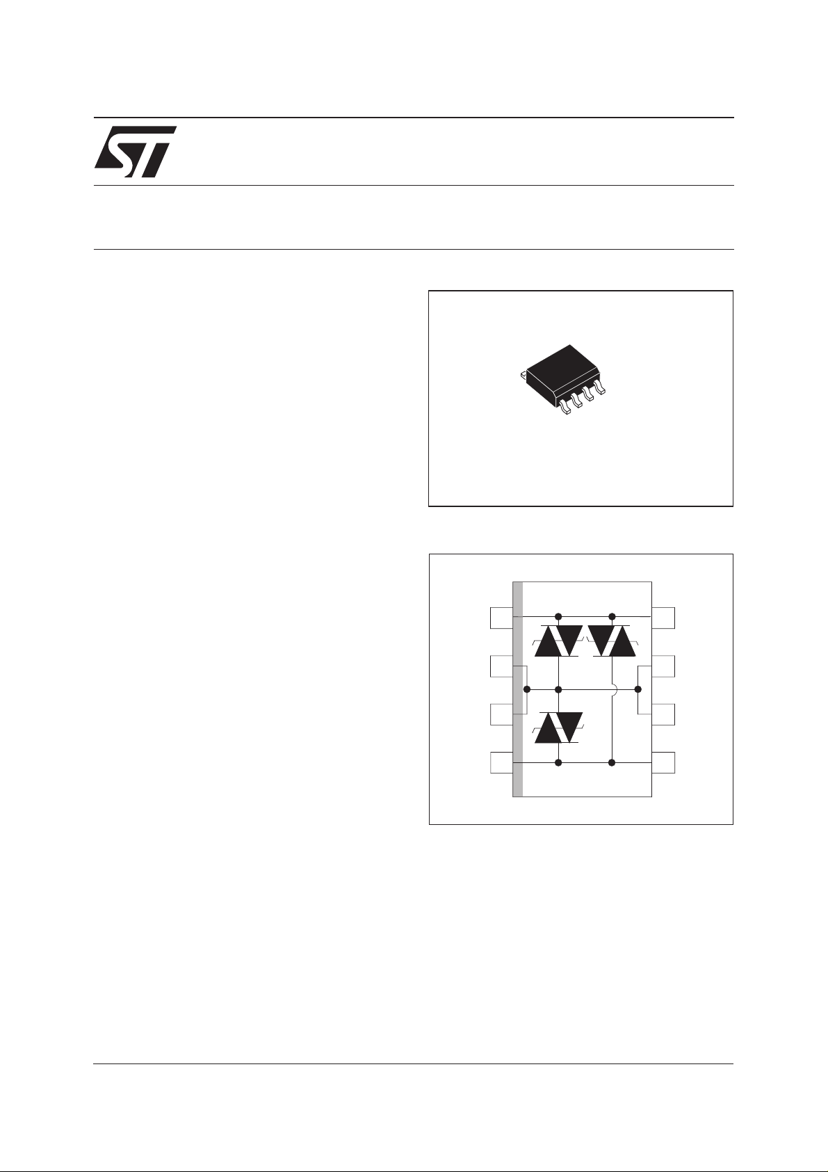
AVAILABLE IN SO-8 PACKAGES.
■
LOW DYNAMIC BREAKOVER VOLTAGE :
■
TPI80N : 150V
TPI120 : 200V
DESCRIPTION
Dedicated devices for ISDN interface and high
speed data telecom line protection. Equivalent to
a triple TRISIL with low capacitance.
These devices provide :
- low capacitance from lines to ground, allowing
high speed transmission without signal
attenuation.
-
good capacitance balance between lines in
order to ensure longitudinal balance.
-
fixed breakdown voltage in both common and
differential modes.
-
the same surge current capability in both
common and differential modes.
-
A particular attention has been given to the
internal wire bonding. The “4-point”
configuration ensures a reliable protection,
eliminating overvoltages introduced by the
parasitic inductances of the wiring (Ldi/dt),
especially for very fast transient overvoltages.
TPI12011N
TRIPOLAR PROTECTION
FOR ISDN INTERFACES
SO-8
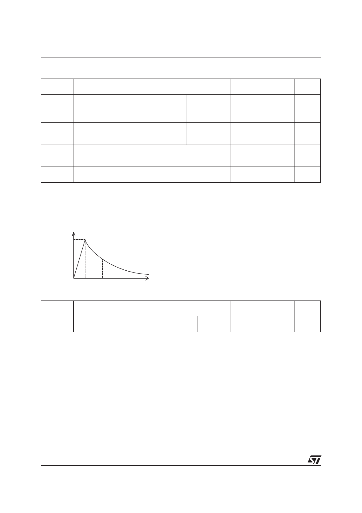
SCHEMATIC DIAGRAM
Tip
GND
GND
Ring
1
2
3
4
8
Tip
7
GND
GND
6
5
Ring
COMPLIES WITH THE FOLLOWING STANDARDS :
CCITT K17 - K20 10/700 µs 1.5 kV
5/310 µs38A
VDE 0433 10/700 µs2kV
5/310 µs50A
VDE 0878 1.2/50 µs 1.5 kV
1/20 µs40A
CNET 0.5/700 µs 1.5 kV
0.2/310 µs38A
TM: ASDisa trademark of STMicroelectronics.
August 2001- Ed : 3A
1/7
TPI8011N/TPI12011N
ABSOLUTE MAXIMUM RATINGS (T
amb
=25°C)
Symbol Parameter Value Unit
I
I
TSM
PP
Peak pulse current (see note 1)
Non repetitive surge peak on-state
current (F = 50 Hz).
T
stg
T
j
T
L
Note 1 : Pulse waveform :
Storage temperature range
Maximum junction temperature
Maximum lead temperature for soldering during 10s
10/1000µst
5/310µst
2/10µst
%I
PP
100
=10µst
r
=5µst
r
=2µst
r
=1000µs
p
=310µs
p
=10µs
p
10/1000 µs
5/320 µs
2/10 µs
tp=10ms
t=1s
30
40
90
8
3.5
-55to+150
150
260 °C
A
A
°C
50
0
t
t
p
r
t
THERMAL RESISTANCES
Symbol Parameter Value Unit
R
th (j-a)
Junction to ambient
SO-8 170 °C/W
2/7
TPI8011N/TPI12011N
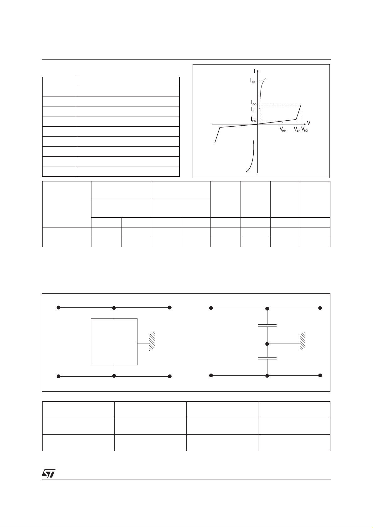
ELECTRICAL CHARACTERISTICS (
Symbol Parameter
V
RM
I
RM
V
BR
V
BO
I
H
I
BO
I
PP
V
F
C
Types
Stand-off voltage
Leakage current
Breakdown voltage
Breakover voltage
Holding current
Breakover current
Peak pulse current
Forward Voltage Drop
Capacitance
@V
I
RM
RM
max. min. max. typ. max. min.
µAV VmAV VmAmA
TPI8011N
TPI12011N
10 70 80 1 120 150 800 150
10 105 120 1 180 200 800 150
Tamb
=25°C)
VBR@I
R
V
BO
VBO
dyn.
I
BO
I
H
note1 note2 note1 note3
Note 1 : See the reference test circuit 1.
Note 2 : Surge test according to CCITT 1.5kV,10/700 µs between Tip or Ring and ground.
Note 3 : See functional holding current test circuit 2.
CAPACITANCES CHARACTERISTICS
LINE A
LINE A
TPIxx
LINE B
CONFIGURATION
=1V
V
A
=56V
V
B
= 56V
V
A
=1V
V
B
C
(pF)
A
max
70 50 30
50 70 30
LINE B
CB(pF)
max
C
A
C
B
CA-CB(pF)
max
3/7
 Loading...