


UM2587
User manual
Getting started with the P-NUCLEO-LRWAN2 and P-NUCLEO-LRWAN3
starter packs
Introduction
This user manual describes how to get started with the P-NUCLEO-LRWAN2 and P-NUCLEO-LRWAN3 starter packs.
Hardware and software setups are discussed in detail, together with the setup of supported network and application servers.
The P-NUCLEO-LRWAN2 starter pack supports the higher frequency bands (868 MHz and 915 MHz). It includes:
•
A sensor node based on STMicroelectronics NUCLEO-L073RZ Nucleo board and USI® I-NUCLEO-LRWAN1 LoRa
expansion board with antenna
•
A LoRaWAN® gateway based on STMicroelectronics NUCLEO-F746ZG Nucleo board and RisingHF LRWAN_GS_HF1
expansion board with antenna
The P-NUCLEO-LRWAN3 starter pack supports the lower frequency bands (433 MHz and 470 MHz). It includes:
•
A sensor node based on STMicroelectronics NUCLEO-L073RZ Nucleo board and RisingHF LRWAN_NS1 LoRa
expansion board
•
A LoRaWAN® gateway based on STMicroelectronics NUCLEO-F746ZG Nucleo board and RisingHF LRWAN_GS_LF1
expansion board
• Antennas
This user manual also describes the I-CUBE-LRWAN STM32Cube Expansion Package for the sensor node, and the gateway
binary software.
®
®
Figure 1. P-NUCLEO-LRWAN2 and P-NUCLEO-LRWAN3 - LoRaWAN® sensors and gateways
P-NUCLEO-LRWAN2 P-NUCLEO-LRWAN3
Sensor
Pictures are not contractual.
Gateway
Gateway
Sensor
UM2587 - Rev 2 - April 2021
For further information contact your local STMicroelectronics sales office.
www.st.com

1 P-NUCLEO-LRWAN2 starter pack overview
Figure 2 shows an overview of the P-NUCLEO-LRWAN2 starter pack, which includes a LoRaWAN® sensor
device and gateway as well as the antennas.
Instructions at the back of the insert card guide the users on how to power up and configure the sensor device
and gateway and setup the network.
The starter pack is configured to use the EU868 frequency band with the sensor device in OTAA mode and
the gateway forwarding the packets to Loriot EU1 server. The pack is user configurable by firmware and by AT
commands.
Figure 2. STM32 Nucleo LoRaWAN® development kit (P-NUCLEO-LRWAN2 starter pack)
UM2587
P-NUCLEO-LRWAN2 starter pack overview
UM2587 - Rev 2
The antennas in this product are assembled and locked with the boards, which was not the case in earlier
versions. They do not have to be removed by users to comply with FCC regulations. The current product
packaging is adapted to this configuration. Visuals and illustrations in the related technical documents may differ
from the current product version.
page 2/51

1.1 Sensor hardware overview
The P-NUCLEO-LRWAN2 LoRaWAN® sensor device has the following key features:
Main board
• NUCLEO-L073RZ development board (from STMicroelectronics)
– STM32L073RZT6 Arm® Cortex®-M0+ ultra-low-power MCU at 32 MHz with 192-Kbyte Flash memory,
20-Kbyte SRAM and 6-Kbyte data EEPROM
– 1 user LED
– 1 user and 1 reset push-buttons
– 32.768 kHz crystal oscillator
– On-board ST-LINK/V2-1 debugger/programmer with USB re-enumeration capability: mass storage,
Virtual COM port, and debug port
– Board connectors
◦ Mini-AB USB connector for the ST-LINK
◦
ARDUINO® Uno V3 expansion connector
◦ ST morpho extension pin headers for full access to all STM32 I/Os
RF module and sensor expansion board
UM2587
Sensor hardware overview
•
I-NUCLEO-LRWAN1 LoRa® HF band (868/915/923 MHz) sensor expansion board (from USI®)
– USI® WM-SG-SM-42 low-power long-range LoRaWAN® module, based on the STM32L052 MCU and
Semtech SX1272 transceiver
– STMicroelectronics HTS221 temperature and humidity sensor
– STMicroelectronics LPS22HB pressure sensor
– STMicroelectronics LSM303AGR accelerometer and gyroscope sensor
Note: Arm is a registered trademark of Arm Limited (or its subsidiaries) in the US and/or elsewhere.
All other trademarks are the property of their respective owners.
Figure 3 shows the two boards in the P-NUCLEO-LRWAN2 LoRaWAN® sensor device.
UM2587 - Rev 2
page 3/51

ST-LINK
®
Arm
Mbed™
removable
storage
USB VCOM
STM32L073RZT6
microcontroller
Sensor hardware overview
Figure 3. STM32 Nucleo LoRaWAN® sensor device (P-NUCLEO-LRWAN2)
®
USI
module
UM2587
Sensors:
LSM303AGR
LPS22HB
HTS221
NUCLEO-L073RZ
main board
I-NUCLEO-LRWAN1
expansion board
UM2587 - Rev 2
page 4/51

XTAL
32 MHz
SX1272
(860 M Hz – 1020 MHz)
STM32L052T8Y6
64-Kbyte Flash
8-Kbyte RAM
2-Kbyte EEPROM
SPI1
RESET
DIO 0-4
Antenna
RFI
VR_PA
RF SWITCH
PA_BOOST
U.FL
XTAL
32.768 kHz
ANT TX/RX
ADC 1 – 3
UM2587
Sensor hardware overview
1.1.1
I-NUCLEO-LRWAN1 LoRa® HF band and sensor expansion board
The I-NUCLEO-LRWAN1 is supplied by a third party (USI®). For complete and latest information, refer to the third
party GitHub page https://github.com/USILoRaModule/USI_I-NUCLEO-LRWAN1.
Figure 4. I-NUCLEO-LRWAN1 block diagram and connectors
Note: The Nucleo board communicates with the expansion board via the STM32 UART (PA2, PA3). The following
modifications are applied to the Nucleo board:
• SB62 and SB63 are closed
• SB13 and SB14 are opened to disconnect the STM32 UART from ST-LINK
UM2587 - Rev 2
page 5/51

1.2 Gateway hardware overview
The P-NUCLEO-LRWAN2 LoRaWAN® gateway shown in Section 1.2 has the following key features:
Gateway main board
• NUCLEO-F746ZG development board (from STMicroelectronics)
– STM32F746ZGT6 Arm® Cortex®-M7 high-performance MCU at 216 MHz with 1-Mbyte Flash memory
and 320-Kbyte SRAM
– 3 user LEDs
– 1 user and 1 reset push-buttons
– Ethernet compliant with IEEE-802.3-2002
– USB OTG full speed or device only
– 32.768 kHz crystal oscillator
– On-board ST-LINK/V2-1 debugger/programmer with USB re-enumeration capability: mass storage,
Virtual COM port, and debug port
– Board connectors
◦ Micro-AB USB connector for the ST-LINK
◦
ST Zio expansion connector including ARDUINO® Uno V3
◦ ST morpho extension pin headers for full access to all STM32 I/Os
◦ USB with Micro-AB
◦ Ethernet RJ45
UM2587
Gateway hardware overview
Gateway expansion board
• LRWAN_GS_HF1 LoRa® HF band (868/915/923 MHz) gateway expansion board (from RisingHF)
– SX1301/SX1257 HF baseband data concentrator and transceiver
◦ Automatically adaptive to spreading factor from SF12 to SF7 in each of 8 channels
◦ High sensitivity down to -140 dBm at 300 bit/s
◦ 6 dBm output power
◦ Support LoRaWAN® protocol Class A and Class C
◦ Support Semtech packet forwarder
◦ Support DNS and NTP
UM2587 - Rev 2
page 6/51

Gateway hardware overview
Figure 5. STM32 Nucleo LoRaWAN® gateway (P-NUCLEO-LRWAN2)
UM2587
Gateway additional features
• Programmable parallel demodulation paths
• LoRa® demodulators and 1 GFSK demodulator embedded
• Single +5 V supply
• AT command interface to re-configure the parameters of the gateway
– change frequency plan
– change IP of the gateway
– change MAC address and ID of the gateway
– change network server that supports Semtech packet forwarder
– set to use public server or private server
– change DNS address
– change NTP server address
UM2587 - Rev 2
page 7/51

1.2.1 Gateway expansion board
The LRWAN_GS_HF1 gateway expansion board shown in Figure 6 is designed by RisingHF (www.risinghf.com).
It includes a Semtech SX1301 digital baseband circuit integrating the LoRa® concentrator, Semtech SX1257 HF
front-end transceiver module, and two SAW filters to achieve a wider bandwidth range (868 MHz to 915 MHz).
The expansion board is controlled by the NUCLEO-F746ZG via the SPI interface.
The gateway expansion board includes also an external +5 V power supply circuitry, which powers both the
gateway expansion board and NUCLEO-F746ZG development board. The NUCLEO-F746ZG is powered via pin
VIN (Pin 15 of connector CN8 on the Nucleo board).
For more details, refer to [3].
Figure 6. Gateway expansion board (P-NUCLEO-LRWAN2)
ANT connector
(with protection cap)
LF/HF identification
VIN
PF5 – GPIO4
PF10 – GPIO3
UM2587
Gateway hardware overview
PA5 – SCK (optional)
PA6 – MISO (optional)
PA6 – MOSI (optional)
PD14 – CSN (optional)
PD15 – Band Set1
PF12 – RST
PF13 – GPIO0
PE9 – Band Set2
PE11 – CSN
PF14 – GPIO1
PE13 – MISO
PF15 – GPIO2
PE12 – SCK
PE14 – MOSI
USB for external 5 V supply
Table 1. P-NUCLEO-LRWAN2 gateway expansion board pins description
Pin name
VIN Power supply to NUCLEO-F746ZG from external 5 V
PF5/PD12/PC4/PB9 -GPIO4 GPIO4 from SX1301
PF10/PD13/PC5/PB8 -GPIO3 GPIO3 from SX1301
PF15-GPIO2 GPIO2 from SX1301
PF14-GPIO1 GPIO1 from SX1301
PF13-GPIO0 GPIO0 from SX1301
PE11-CSN CSN of SPI for SX1301
Pin description
UM2587 - Rev 2
page 8/51

Pin name Pin description
PE13-MISO MISO of SPI for SX1301
PE12-SCK SCK of SPI for SX1301
PE14-MOSI MOSI of SPI for SX1301
PE15-RST Reset for SX1301
PD15-Band Set1 ST Nucleo LoRa GW HF
PE9-Band Set2
PA5-SCK (optional)
PA6-MISO (optional)
PA7/PB5-MOSI (optional)
PD14-CSN (optional)
• PE9=0, PD15=1: Band EU868
• PE9=1, PD15=0: Band US915/AS915/AU915
Backup SCK of SPI for SX1301
(no connection on board in default)
Backup MISO of SPI for SX1301
(no connection on board in default)
Backup MOSI of SPI for SX1301
(no connection on board in default)
Backup CSN of SPI for SX1301
(no connection on board in default)
UM2587
Gateway hardware overview
Figure 7 presents the architecture of the LRWAN_GS_HF1 gateway expansion board.
Figure 7. Hardware architectures of the P-NUCLEO-LRWAN2 gateway expansion board
Balun LTCC LPF
Transceiver
SX1257
SAW
868 MHz
Baseband
SX1301
LNA
SW
SAW
Transceiver
915 MHz
SX1257
Legend:
HF specific
SW
Emission
SW
Reception
UM2587 - Rev 2
page 9/51

P-NUCLEO-LRWAN3 starter pack overview
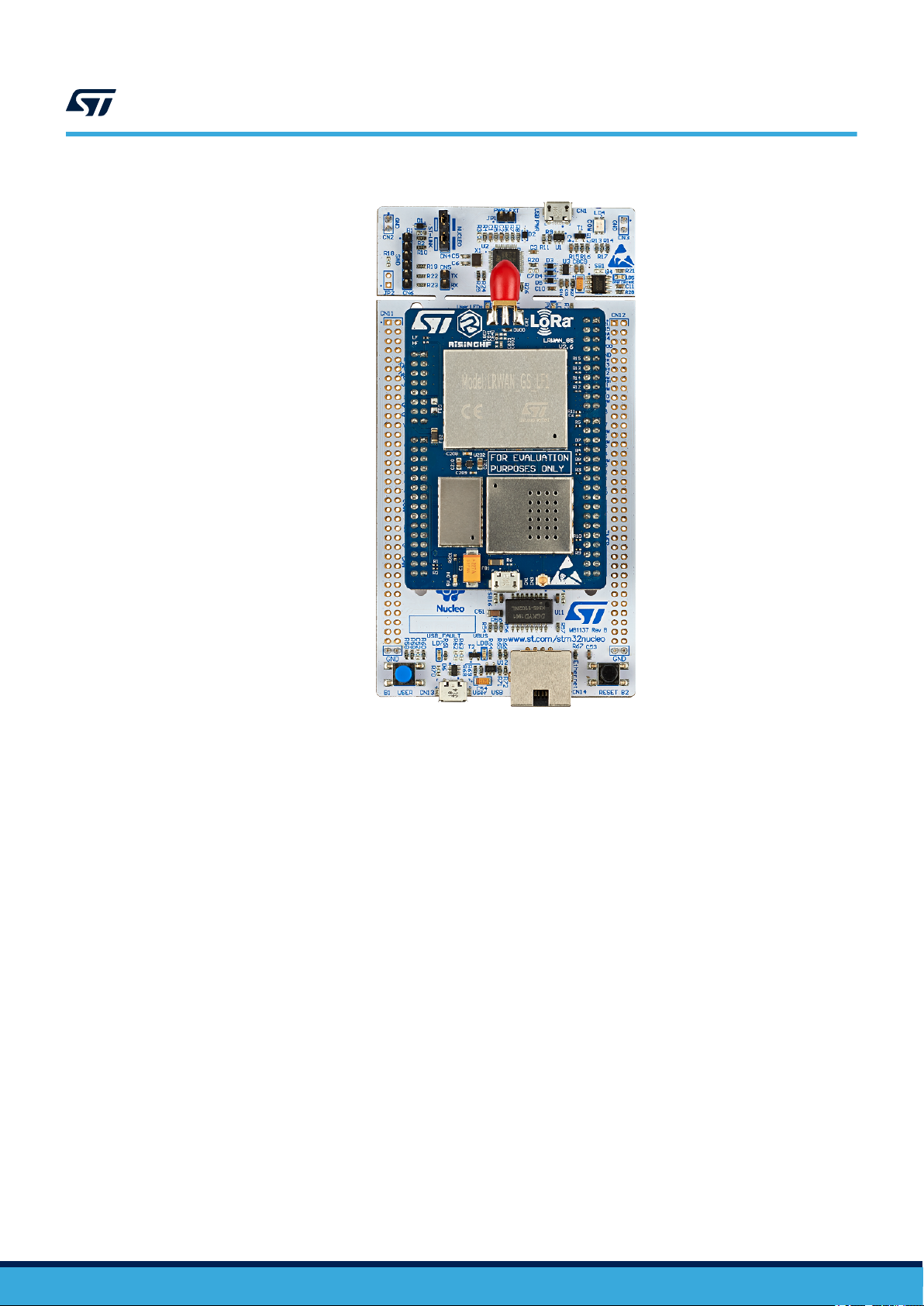
2 P-NUCLEO-LRWAN3 starter pack overview
Figure 8 shows an overview of the P-NUCLEO-LRWAN3 starter pack, which includes a LoRaWAN® sensor
device and gateway as well as the antennas.
Instructions at the back of the insert card guide the users on how to power up and configure the sensor device
and gateway and setup the network.
The starter pack is configured to use the CN470Prequel frequency band with the sensor device in OTAA mode
and the gateway forwarding the packets to Loriot CN1 server. The pack is user configurable by firmware and by
AT commands.
Figure 8. STM32 Nucleo LoRaWAN® development kit (P-NUCLEO-LRWAN3 starter pack)
UM2587
2.1 P-NUCLEO-LRWAN3 starter pack known limitation
The serial number of the NUCLEO-L073RZ MB1136 reference board is indicated on a sticker under the MB1136.
If the number is within the range from A191400001 to A191402004, the board must be updated with a new
firmware before use. Download the last firmware version available at www.st.com/i-cube-lrwan.
UM2587 - Rev 2
page 10/51

2.2 Sensor hardware overview
The P-NUCLEO-LRWAN3 LoRaWAN® sensor device has the following key features:
Main board
• NUCLEO-L073RZ development board (from STMicroelectronics)
– STM32L073RZT6 Arm® Cortex®-M0+ ultra-low-power MCU at 32 MHz with 192-Kbyte Flash memory,
20-Kbyte SRAM and 6-Kbyte data EEPROM
– 1 user LED
– 1 user and 1 reset push-buttons
– 32.768 kHz crystal oscillator
– On-board ST-LINK/V2-1 debugger/programmer with USB re-enumeration capability: mass storage,
Virtual COM port, and debug port
– Board connectors
◦ Mini-AB USB connector for the ST-LINK
◦
ARDUINO® Uno V3 expansion connector
◦ ST morpho extension pin headers for full access to all STM32 I/Os
RF module and sensor expansion board
UM2587
Sensor hardware overview
•
LRWAN_NS1 LoRa® LF band (433/470 MHz) sensor expansion board (from RisingHF)
– RisingHF RHF0M003-LF20 low-power long-range LoRaWAN® module, based on the STM32L071
MCU and Semtech SX1278 transceiver
◦ High sensitivity down to -137 dBm
◦ 14 dBm to 20 dBm output power
– STMicroelectronics HTS221 temperature and humidity sensor
– STMicroelectronics LPS22HB pressure sensor
– STMicroelectronics LSM6DS3 accelerometer and gyroscope sensor
– STMicroelectronics LIS3MDL magnetometer
Figure 9 shows the two boards in P-NUCLEO-LRWAN3 LoRaWAN® sensor device.
UM2587 - Rev 2
page 11/51

Sensor hardware overview
Figure 9. STM32 Nucleo LoRaWAN® sensor device (P-NUCLEO-LRWAN3)
UM2587
ST-LINK
®
Arm
Mbed™
removable
storage
USB VCOM
STM32L073RZT6
microcontroller
NUCLEO-L073RZ
main board
LSM6DS3
Sensors:
LPS22HB
LIS3MDL
LRWAN_NS1
expansion board
HTS221
RisingHF
module
UM2587 - Rev 2
page 12/51

UM2587
Sensor hardware overview
2.2.1
LRWAN_NS1 LoRa® LF band and sensor expansion board
The LRWAN_NS1 is supplied by a third party (RisingHF). For complete and latest information, refer to
LRWAN_NS1 reference manual [2].
Figure 10. LRWAN_NS1 block diagram and connectors
UM2587 - Rev 2
page 13/51

UM2587
Gateway hardware overview
Note: By default, USART1 (PA9/PA10) is used in the NUCLEO-L073RZ board to control the RHF0M003-LF20 modem.
Optionally, it is possible to use USART2 (PA2/PA3) via jumper resistor on the LRWAN_NS1. Refer to its user
manual. If USART2 (PA2/PA3) is used to control the modem, the following solder bridge on the Nucleo board
must be configured accordingly:
• SB62 and SB63 are closed
• SB13 and SB14 are opened to disconnect the STM32 UART from ST-LINK
Refer to [5] in the USART Communication section for more details.
2.3 Gateway hardware overview
The P-NUCLEO-LRWAN3 LoRaWAN® gateway shown in Figure 11 has the following key features:
Gateway main board
• NUCLEO-F746ZG development board (from STMicroelectronics)
– STM32F746ZGT6 Arm® Cortex®-M7 high-performance MCU at 216 MHz with 1-Mbyte Flash memory
and 320-Kbyte SRAM
– 3 user LEDs
– 1 user and 1 reset push-buttons
– Ethernet compliant with IEEE-802.3-2002
– USB OTG full speed or device only
– 32.768 kHz crystal oscillator
– On-board ST-LINK/V2-1 debugger/programmer with USB re-enumeration capability: mass storage,
Virtual COM port, and debug port
– Board connectors
◦ Micro-AB USB connector for the ST-LINK
◦
ST Zio expansion connector including ARDUINO® Uno V3
◦ ST morpho extension pin headers for full access to all STM32 I/Os
◦ USB with Micro-AB
◦ Ethernet RJ45
Gateway expansion board
• LRWAN_GS_LF1 LoRa® LF band (433/470 MHz) gateway expansion board (from RisingHF)
– Semtech SX1301/SX1255 LF baseband data concentrator and transceiver
◦ Automatically adaptive to spreading factor from SF12 to SF7 in each of 8 channels
◦ High sensitivity down to -140 dBm at 300 bit/s
◦ 6 dBm output power
◦ Support LoRaWAN® protocol Class A and Class C
◦ Support Semtech packet forwarder
◦ Support DNS and NTP
UM2587 - Rev 2
page 14/51
Gateway hardware overview
Figure 11. STM32 Nucleo LoRaWAN® gateway (P-NUCLEO-LRWAN3)
UM2587
Gateway additional features
• Programmable parallel demodulation paths
• LoRa® demodulators and 1 GFSK demodulator embedded
• Single +5 V supply
• AT command interface to re-configure the parameters of the gateway
– change frequency plan
– change IP of the gateway
– change MAC address and ID of the gateway
– change network server that supports Semtech packet forwarder
– set to use public server or private server
– change DNS address
– change NTP server address
UM2587 - Rev 2
page 15/51

2.3.1 Gateway expansion board
The gateway expansion board shown in is designed by RisingHF (www.risinghf.com). It includes a Semtech
SX1301 digital baseband circuit integrating the LoRa® concentrator, Semtech SX1255 LF front-end transceiver
module, and two SAW filters to achieve a wider bandwidth range (434 MHz to 470 MHz). The expansion board is
controlled by the NUCLEO-F746ZG via the SPI interface.
The gateway expansion board includes also an external +5 V power supply circuitry, which powers both the
gateway expansion board and NUCLEO-F746ZG development board. The NUCLEO-F746ZG is powered via pin
VIN (Pin 15 of connector CN8 on the Nucleo board).
For more details, refer to [3].
Figure 12. Gateway expansion board (P-NUCLEO-LRWAN3)
ANT connector
(with protection cap)
LF/HF identification
VIN
PF5 – GPIO4
PF10 – GPIO3
UM2587
Gateway hardware overview
PA5 – SCK (optional)
PA6 – MISO (optional)
PA6 – MOSI (optional)
PD14 – CSN (optional)
PD15 – Band Set1
PF12 – RST
PF13 – GPIO0
PE9 – Band Set2
PE11 – CSN
PF14 – GPIO1
PE13 – MISO
PF15 – GPIO2
PE12 – SCK
PE14 – MOSI
USB for external 5 V supply
Table 2. P-NUCLEO-LRWAN3 gateway expansion board pins description
Pin name
VIN Power supply to NUCLEO-F746ZG from external 5 V
PF5/PD12/PC4/PB9 -GPIO4 GPIO4 from SX1301
PF10/PD13/PC5/PB8 -GPIO3 GPIO3 from SX1301
PF15-GPIO2 GPIO2 from SX1301
PF14-GPIO1 GPIO1 from SX1301
PF13-GPIO0 GPIO0 from SX1301
PE11-CSN CSN of SPI for SX1301
Pin description
UM2587 - Rev 2
page 16/51

Pin name Pin description
PE13-MISO MISO of SPI for SX1301
PE12-SCK SCK of SPI for SX1301
PE14-MOSI MOSI of SPI for SX1301
PE15-RST Reset for SX1301
PD15-Band Set1 ST Nucleo LoRa GW LF
PE9-Band Set2
PA5-SCK (optional)
PA6-MISO (optional)
PA7/PB5-MOSI (optional)
PD14-CSN (optional)
• PE9=0, PD15=1: band EU433
• PE9=1, PD15=0: band CN470
Backup SCK of SPI for SX1301
(no connection on board in default)
Backup MISO of SPI for SX1301
(no connection on board in default)
Backup MOSI of SPI for SX1301
(no connection on board in default)
Backup CSN of SPI for SX1301
(no connection on board in default)
UM2587
Gateway hardware overview
Figure 13 presents the architecture of the LRWAN_GS_LF1 gateway expansion board.
Figure 13. Hardware architecture of the P-NUCLEO-LRWAN3 gateway expansion board
Balun LTCC LPF
Transceiver
SX1255
SAW
434 MHz
Baseband
SX1301
LNA
SW
SAW
Transceiver
470 MHz
SX1255
Legend:
LF specific
SW
Emission
SW
Reception
UM2587 - Rev 2
page 17/51

P-NUCLEO-LRWAN2 / P-NUCLEO-LRWAN3 firmware overview
3 P-NUCLEO-LRWAN2 / P-NUCLEO-LRWAN3 firmware overview
The P-NUCLEO-LRWAN2 and P-NUCLEO-LRWAN3 starter packs include the following firmware:
• I-CUBE-LRWAN LoRaWAN® STM32Cube Expansion Package for the microcontrollers in the STM32L0
Series, STM32L1 Series, STM32L4 Series, and STM32L4+ Series
• Binary for the STM32F746ZGT6 microcontroller of the LoRaWAN® gateway Nucleo board
UM2587
3.1
I-CUBE-LRWAN LoRaWAN® STM32Cube Expansion Package
The I-CUBE-LRWAN Expansion Package consists of a set of libraries and application examples for STM32L0
Series, STM32L1 Series, STM32L4 Series, and STM32L4+ Series microcontrollers acting as end-devices. This
firmware Expansion Package is downloadable from www.st.com/en/product/i-cube-lrwan.
A specific firmware project called AT_Master is an example code available only for the STM32L0 Series
microcontroller interfacing either with the I-NUCLEO-LRWAN1 USI® LoRa® expansion board, or with the
LRWAN_NS1 RisingHF LoRa® expansion board. The AT_Master sample project implements a host AT_Master
application that controls the LoRa® modem via AT commands, establishes a link with the LoRaWAN® network,
and sends sensor data.
Figure 14. AT_Master in LoRaWAN® STM32Cube Expansion Package
3.2
UM2587 - Rev 2
STM32F7 Nucleo LoRaWAN® gateway firmware
Firmware is based on the Semtech packet forwarder protocol ported over to the STM32F746ZGT6 device. The
gateway parameters are fully reconfigurable by means of the AT command interface through the ST-LINK USB
Virtual COM port. Refer to [3] for details.
page 18/51

STM32F7 Nucleo LoRaWAN® gateway firmware
User reconfigurable parameters by means of the AT command interface
• Frequency plan
• Network server settings
– LoRaWAN® server address (public or private)
– Uplink and downlink port
• Ethernet settings
– MAC address (default based on STM32 unique ID)
– Static or DHCP mode
– IP address, DNS address, NTP server address
• Gateway ID
• Baud rate
• Enabling/disabling log messages
AT command list
Table 3. AT command list
Command Comment
AT
HELP Prints help information.
FDEFAULT Resets to factory default settings.
RESET Software-reset gateway.
SYS Checks all configurations.
VER Gets version.
LOG Turns on/off packet forwarder log.
ECHO AT command echo on/off.
MAC Sets/gets the gateway MAC address.
IP DHCP/static IP control.
DNS Sets/gets the DNS address.
NTP Sets/gets the NTP server address.
EUI MAC Address (EUI48) to Gateway ID (EUI64) padding.
LORAWAN
PKTFWD Packet forwarder server address and port settings.
CH Packet forwarder channels.
Baudrate AT command and logging UART interface baud rate.
Returns +OK.
LoRaWAN® network selection (public/private).
UM2587
UM2587 - Rev 2
The gateway firmware binary is available upon request directly from STMicroelectronics.
To reprogram the board, copy and paste, or drag and drop the binary file to the mbed storage device of the
NUCLEO-F746ZG. The STM32 ST-LINK Utility (STSW-LINK004) programming software is another solution to
program the board.
It is recommended to power the board first before connecting the board with the PC. Refer to Section 6 about
how to power the board.
page 19/51

UM2587
STM32F7 Nucleo LoRaWAN® gateway firmware
Figure 15. Programming the gateway using a binary file
At startup, firmware checks for frequency band setting compatibility versus RF hardware. It displays a warning if
the setting is not compatible with the hardware.
UM2587 - Rev 2
page 20/51

I-NUCLEO-LRWAN1 sensor device setup and reconfiguration
4 I-NUCLEO-LRWAN1 sensor device setup and reconfiguration
This section describes the steps to setup the I-NUCLEO-LRWAN1 sensor device and if necessary, reconfigure
it to the desired frequency band. By default, the device is configured for the EU868 frequency band and in the
OTAA mode.
4.1 Sensor device setup
1. Make sure that the USB drivers are installed. Download ST-LINK USB driver (STSW-LINK009) from
www.st.com if needed.
Figure 16. ST-LINK driver installation
UM2587
Run the batch file to install
2. On the LoRa® expansion board, connect the antenna to connector J1 (for P-NUCLEO-LRWAN3).
Figure 17. Antenna and personal computer connection
CN1 connector
for the USB Mini-B cable
J1 connector
for the antenna
UM2587 - Rev 2
3. Connect the Nucleo board to a personal computer with a USB Type-A or USB Type-C® to Mini-B cable
through USB connector CN1 to the power the board. Then red LED LD3 (PWR) and LD1 (COM) light up.
page 21/51

Extracting DevEUI and AppEUI from the LoRa® module
4. Allow the personal computer to enumerate and install the USB drivers.
Take note of the Virtual COM port number assigned to the board.
Note: the Nucleo board is also enumerated as an mbed removable storage device.
Figure 18. USB enumerated instances
UM2587
4.2
Extracting DevEUI and AppEUI from the LoRa® module
Device enrollment to the network server requires activation parameters stored in the LoRa® module. Depending
on the join mode used (OTAA/ABP), the pieces of information presented in Table 4 need to be extracted from the
LoRa® module (default) or changed.
Table 4. Device activation and parameters (P-NUCLEO-LRWAN2)
Parameters Description
DevEUI
AppEUI
AppKey
NwkSKey
AppSKey
DevAddr
64-bit global unique ID that uniquely identifies the end-device (IEEE EUI64
address).
64-bit application ID that uniquely identifies the application provider (owner) of
the end-device (IEEE EUI64 address).
AES-128 application key, specific to the end-device, assigned by the
application provider, that is used to derive the session keys, NwkSKey
and AppSKey specific to that end-device to encrypt and verify network
communication and application data.
Network session key, specific to the end-device. Used by the network server
and end-device to calculate and verify the MIC (message integrity code) and
further encrypt and decrypt the payload field of MAC-only data messages.
Application session key, specific to the end-device. Used by both the network
server and the end-device to encrypt and decrypt the payload field of 30
application-specific data messages.
32-bit address that identifies the end-device within the current network.
End-device
activation
OTAA
ABP
UM2587 - Rev 2
Send a get AT command to extract the default parameters of the USI® WM-SG-SM-42 LoRa® module through its
serial port. Refer to [1] for details.
• Get Device EUI (AT+EUI)
• Get Application EUI (AT+APPEUI)
• Get Application Key (AT+AK)
page 22/51

UM2587
Extracting DevEUI and AppEUI from the LoRa® module
The I-NUCLEO-LRWAN1 expansion board uses the serial interface (CN8 pin 1 (Tx) and pin 2 (Rx)) shown in
Figure 19 for the AT command console. The default serial configuration is:
• Baud rate: 115200
• Data: 8 bit
• Parity: none
• Stop: 1 bit
Figure 19. I-NUCLEO-LRWAN1 expansion board serial port
+3V3 (CN6 pin 4)
GND (CN6 pin 6)
LPUART1_Rx (CN8 pin 2)
LPUART1_Tx (CN8 pin 1)
Alternatively, since preloaded firmware reads the DevEUI and AppEUI parameters of the module and saves them
to the internal data memory of the STM32L073RZT6 (Data Memory Bank 1 of the NUCLEO-L073RZ Nucleo
board), the user can extract both parameters by reading the data memory using the STM32 ST-LINK Utility
(STSW-LINK004) or the STM32CubeProgrammer (STM32CubeProg).
Follow these steps to extract DevEUI and AppEUI using the STM32 ST-LINK Utility:
1. Download STM32 ST-LINK Utility (STSW-LINK004) from STMicroelectronics web site and install it
2. Connect the NUCLEO-L073RZ Nucleo board with the personal computer by means of the USB
3. Open a Windows® Command prompt and set the path for the STM32 ST-LINK Utility:
SET PATH=%PATH%;C:\Program Files (x86)\STMicroelectronics\STM32 ST-LINK
Utility\ST-LINK Utility
4. Read DEvUI and AppEui using STM32 ST-LINK Utility CLI command:
– For DevEUI: ST-LINK_CLI.exe -c swd ur -r8 0x08080000 0x08
– For AppEUI: ST-LINK_CLI.exe -c swd ur -r8 0x08080008 0x08
The addresses in the CLI commands are for Data Memory Bank 1 of the NUCLEO-L073RZ Nucleo board.
Note: The STM32 ST-LINK Utility (STSW-LINK004) GUI can also be used to read the data memory of the NUCLEO-
L073RZ.
A similar process is possible using the STM32CubeProgrammer (STM32CubeProg). Refer to
STM32CubeProgrammer documentation on www.st.com.
UM2587 - Rev 2
page 23/51

Reconfiguring the sensor device using the AT_Master project
4.3 Reconfiguring the sensor device using the AT_Master project
Edit firmware to change join mode, frequency band, device IDs, and keys. More parameters are reconfigurable.
The following examples show functions used to set these parameters in user firmware.
In file main.c:
#define JOIN_MODE OTAA_JOIN_MODE /*ABP_JOIN_MODE*/ /*LoRaWan join method*/
In file lora_driver.c:
• Lora_SetDeviceBand(uint8_t DeviceBand) → Sets the band plan
• LoRa_SetDeviceID(uint8_t *PtrDeviceID) → Sets the device ID (DevEUI)
• LoRa_SetAppID(uint8_t *PtrAppID) → Sets the application identifier (AppEUI)
• LoRa_SetDeviceAddress(uint32_t DeviceAddr) → Sets the device address (DevAddr)
• LoRa_SetKey(ATCmd_t KeyType, uint8_t *PtrKey) → Sets the key configuration (APPKEY,
NWKSKE, APPSKEY)
• Lora_UpdateConfigTable() → Updates the DCT content table with new values
The corresponding Get functions are also available.
Alternatively, it is possible to reconfigure the WM-SG-SM-42 module directly via its serial port by sending AT
commands from the PC. Refer to [1] for details.
Set additional options in the hw_conf.h file in folder AT_Master:
• Low-power mode: enables/disables the low-power mode
• Sensor-enable switch: enables reading the data from the sensors in the I-NUCLEO-LRWAN1 expansion
board
UM2587
UM2587 - Rev 2
page 24/51

LRWAN_NS1 sensor device setup and reconfiguration
5 LRWAN_NS1 sensor device setup and reconfiguration
This section describes the steps to setup the LRWAN_NS1 sensor device and if necessary, reconfigure it to the
desired frequency band. By default, the device is configured for the CN470Prequel frequency band and in the
OTAA mode.
5.1 Sensor device setup
1. Make sure that the USB drivers are installed. Download ST-LINK USB driver (STSW-LINK009) from
www.st.com if needed.
Figure 20. ST-LINK driver installation
UM2587
Run the batch file to install
2. On the LoRa® expansion board, connect the antenna to connector CN10 (for P-NUCLEO-LRWAN3).
Figure 21. Antenna and personal computer connection
CN1 connector
for the USB Mini-B cable
CN10 connector
for the antenna
UM2587 - Rev 2
3. Connect the Nucleo board to a personal computer with a USB Type-A or USB Type-C® to Mini-B cable
through USB connector CN1 to the power the board. Then red LED LD3 (PWR) and LD1 (COM) light up.
page 25/51

Extracting DevEUI and AppEUI from the LoRa® module
4. Allow the personal computer to enumerate and install the USB drivers.
Take note of the Virtual COM port number assigned to the board.
Note: the Nucleo board is also enumerated as an mbed removable storage device.
Figure 22. USB enumerated instances
UM2587
5. [Optional: to display debug printf messages] Open a terminal emulation software such as Tera Term and
configure it with the following settings for further viewing of the LoRa® device parameters:
– Port: (Virtual COM port number assigned to the board from step 4)
– Baud rate: 9600
– Data: 8 bit
– Parity: none
– Stop: 1 bit
Figure 23. Terminal emulation software settings
9600
5.2
UM2587 - Rev 2
Extracting DevEUI and AppEUI from the LoRa® module
Device enrollment to the network server requires activation parameters stored in the LoRa® module. Depending
on the join mode used (OTAA/ABP), the pieces of information presented in Table 5 need to be extracted from the
LoRa® module (default) or changed.
page 26/51

Extracting DevEUI and AppEUI from the LoRa® module
Table 5. Device activation and parameters(P-NUCLEO-LRWAN3)
UM2587
Parameters Description
DevEUI
AppEUI
AppKey
NwkSKey
AppSKey
DevAddr
64-bit global unique ID that uniquely identifies the end-device (IEEE EUI64
address).
64-bit application ID that uniquely identifies the application provider (owner) of
the end-device (IEEE EUI64 address).
AES-128 application key, specific to the end-device, assigned by the
application provider, that is used to derive the session keys, NwkSKey
and AppSKey specific to that end-device to encrypt and verify network
communication and application data.
Network session key, specific to the end-device. Used by the network server
and end-device to calculate and verify the MIC (message integrity code) and
further encrypt and decrypt the payload field of MAC-only data messages.
Application session key, specific to the end-device. Used by both the network
server and the end-device to encrypt and decrypt the payload field of 30
application-specific data messages.
32-bit address that identifies the end-device within the current network.
End-device
activation
OTAA
ABP
Send a get AT command to extract the default parameters of the RisingHF RHF0M003-LF20 LoRa® module
through its serial port. Refer to [2] for details.
• Get Device EUI (AT+EUI)
• Get Application EUI (AT+APPEUI)
• Get Application Key (AT+AK)
The LRWAN_NS1 LoRa® expansion board uses the serial interface (CN8 pin 1 (Tx) and pin 2 (Rx)) shown in
Figure 24 for the AT command console. The default serial configuration is:
• Baud rate: 9600
• Data: 8 bit
• Parity: none
• Stop: 1 bit
Figure 24. LRWAN_NS1 expansion board serial port
USART1_Tx (CN5 pin 1)
USART1_Tx (CN9 pin 3)
UM2587 - Rev 2
+3V3 (CN6 pin 4) GND (CN6 pin 7/6)
page 27/51

UM2587
Reconfiguring the sensor device using the AT_Master project
Alternatively, since preloaded firmware reads the DevEUI and AppEUI parameters of the module and saves them
to the internal data memory of the STM32L073RZT6 (Data Memory Bank 1 of the NUCLEO-L073RZ Nucleo
board), the user can extract both parameters by reading the data memory using the STM32 ST-LINK Utility
(STSW-LINK004) or the STM32CubeProgrammer (STM32CubeProg).
Follow these steps to extract DevEUI and AppEUI using the STM32 ST-LINK Utility:
1. Download STM32 ST-LINK Utility (STSW-LINK004) from STMicroelectronics web site and install it
2. Connect the NUCLEO-L073RZ Nucleo board with the personal computer by means of the USB
3. Open a Windows® Command prompt and set the path for the STM32 ST-LINK Utility:
SET PATH=%PATH%;C:\Program Files (x86)\STMicroelectronics\STM32 ST-LINK
Utility\ST-LINK Utility
4. Read DEvUI and AppEui using STM32 ST-LINK Utility CLI command:
– For DevEUI: ST-LINK_CLI.exe -c swd ur -r8 0x08080000 0x08
– For AppEUI: ST-LINK_CLI.exe -c swd ur -r8 0x08080008 0x08
The addresses in the CLI commands are for Data Memory Bank 1 of the NUCLEO-L073RZ Nucleo board.
Note: The STM32 ST-LINK Utility (STSW-LINK004) GUI can also be used to read the data memory of the NUCLEO-
L073RZ.
A similar process is possible using the STM32CubeProgrammer (STM32CubeProg). Refer to
STM32CubeProgrammer documentation on www.st.com.
5.3 Reconfiguring the sensor device using the AT_Master project
Edit firmware to change join mode, frequency band, device IDs, and keys. More parameters are reconfigurable.
The following examples show functions used to set these parameters in user firmware.
In file main.c:
#define JOIN_MODE OTAA_JOIN_MODE /*ABP_JOIN_MODE*/ /*LoRaWan join method*/
In file lora_driver.c:
• Lora_SetDeviceBand(uint8_t DeviceBand) → Sets the band plan
• LoRa_SetDeviceID(uint8_t *PtrDeviceID) → Sets the device ID (DevEUI)
• LoRa_SetAppID(uint8_t *PtrAppID) → Sets the application identifier (AppEUI)
• LoRa_SetDeviceAddress(uint32_t DeviceAddr) → Sets the device address (DevAddr)
• LoRa_SetKey(ATCmd_t KeyType, uint8_t *PtrKey) → Sets the key configuration (APPKEY,
NWKSKE, APPSKEY)
• Lora_SetWDT(0) → triggers a module reset so that the new settings will take effect
The corresponding Get functions are also available.
Alternatively, it is possible to reconfigure the RHF0M003-LF20 module directly via its serial port by sending AT
commands from the PC. Refer to [2] for details.
Set additional options in the hw_conf.h file in folder AT_Master:
• Low-power mode: enables/disables the low-power mode
• Sensor-enable switch: enables reading the data from the sensors in the LRWAN_NS1 expansion board
AT command debug printf messages can be sent via ST-LINK Virtual COM port by:
• enabling the definition of CMD_DEBUG in the toolchain preprocessor symbols settings,
• or adding the line
UM2587 - Rev 2
#define CMD_DEBUG
in the user file (e.g. main.c).
page 28/51

6 Gateway setup and configuration
The gateway is a simple packet forwarder based on the Semtech packet forwarder protocol. It needs to be
configured to the desired frequency band and LoRaWAN® network server among other parameters that are
reconfigurable. This can be done by sending AT commands using the Virtual COM port of the Nucleo board.
This section describes the steps to setup the gateway and reconfigure it to the desired frequency band and
network server that supports the Semtech packet forwarder protocol.
6.1 Gateway setup
1. On the NUCLEO-F746ZG board, verify the jumper settings:
– JP1 (PWR-EXT) OFF
– JP3 (power source) on VIN-5V
– JP5 (IDD) ON
2. Connect the NUCLEO-F746ZG board to a network router with an Ethernet cable through Ethernet connector
CN14.
Make sure that the router has DHCP service and Internet access (no password).
3. Connect the antenna to the antenna connector (CN2) (for P-NUCLEO-LRWAN3).
4. On the LoRa® gateway expansion board, connect an external 5 V supply through its USB Micro-B connector
(CN1) to power the whole board.
Important: power supply must be connected to the gateway shield USB port and not with the Nucleo USB
port.
On the Nucleo board, green LED LD6 (PWR) and LD4 (COM) light up. On the gateway shield, the green
LED lights up.
Note: a USB wall adapter/charger is required to power the gateway.
5. To view the gateway MAC address, channel frequency and status, connect the NUCLEO-F746ZG board with
a personal computer by means of a USB Type-A or USB Type-C® to Micro-B cable through USB connector
CN1. View the parameters using a terminal emulation software such as Tera Term.
6. Allow the personal computer to enumerate and install the USB drivers.
Take note of the Virtual COM port number assigned to the board.
7. Open a terminal emulation software such as Tera Term and configure it with the following settings:
– Port: (Virtual COM port number assigned to the board from step 6)
– Baud rate: 115200
– Data: 8 bit
– Parity: none
– Stop: 1 bit
UM2587
Gateway setup and configuration
UM2587 - Rev 2
page 29/51

Configuring the gateway to use a different frequency band
8. Press the reset button B2 (black button) to view the gateway MAC address, channel frequency and
status. These parameters are further used to register the gateway to the network server (refer to
Section 7 Network server setup). The USB cable (Virtual COM) can then be removed when the gateway is
registered.
Figure 25. Gateway parameter settings
UM2587
6.2
P-NUCLEO-LRWAN2
The default setting of the LRWAN_GS_HF1 gateway is set to the EU868 frequency band and Loriot EU1 server.
P-NUCLEO-LRWAN3
The default setting of the LRWAN_GS_LF1 gateway is set to the CN470Prequel frequency band and Loriot CN1
server.
Configuring the gateway to use a different frequency band
The ST Nucleo LoRa GW user guide from RisingHF ([3]) details the reconfiguration of the gateway using AT
commands.
To change the frequency channels, use the AT+CH command. Reset the board for the new settings to take effect.
At startup, firmware checks for the compatibility of the frequency band setting versus RF hardware. It displays a
warning if the setting is not compatible with the hardware.
Set the packet forwarder channels as follows:
UM2587 - Rev 2
page 30/51

UM2587
Configuring the gateway to use a different frequency band
• Format:
AT+CH=0~7,freq,radio // Set multi SF LoRa channel
AT+CH=8,freq,radio,sf,bw // Set standard LoRa channel
AT+CH=9,freq,radio // Set FSK channel
AT+CH=0~9,0 // Turn off a channel
AT+CH=0~9,OFF // Turn off a channel
AT+CH=band // Set to predefined channel plan
• Return:
+CH: 0~7, freq, radio, SF7/SF12, BW125KHz (LORA_MULTI_SF)
+CH: 8, freq, radio, SFx, BWxxxKHz (LORA_STANDARD)
+CH: 9, freq, radio, 50Kbps (FSK)
Refer to [3] for more details.
Predefined channels are available for quick setting of the frequency plan. Use the AT+CH=band command to
use the predefined channels. The available bands are EU868, US915, EU433, CN780, AU915, AS923, KR920,
CN470, CN470 prequel, and IN866. Table 6 shows the corresponding frequencies in MHz.
Table 6. Predefined frequency channel plans
CH EU868 US915 EU433 CN780 AU915 AS923 KR920 CN470
0 867.1 902.3 433.175 779.5 915.2 923.2 922.1 470.3 471.5 865.0625
1 867.3 902.5 433.375 779.7 915.4 923.4 922.3 470.5 471.7 865.2625
2 867.5 902.7 433.575 779.9 915.6 923.6 922.5 470.7 471.9 865.4625
3 867.7 902.9 433.775 780.1 915.8 923.8 922.7 470.9 472.1 865.6625
4 867.9 903.1 433.975 780.3 916.0 924.0 922.9 471.1 472.3 865.985
5 868.1 903.3 434.175 780.5 916.2 924.2 923.1 471.3 472.5 866.185
6 868.3 903.5 434.375 780.7 916.4 924.4 923.3 471.5 472.7 866.385
7 868.5 903.7 434.575 780.9 916.6 924.6 923.5 471.7 472.9 866.585
868.3
8
BW250
SF7
868.8
9
FSK
50 Kbps
903.0
BW500
SF8
OFF OFF OFF OFF OFF OFF OFF OFF OFF
OFF OFF
915.9
BW500
SF8
OFF OFF OFF OFF OFF
CN470
Prequel
For instance, to set the EU868 band plan, send AT command AT+CH=EU868.
AT+CH=EU868
AT+CH=0,867.1,A
AT+CH=1,867.3,A
AT+CH=2,867.5,A
AT+CH=3,867.7,A
AT+CH=4,867.9,B
AT+CH=5,868.1,B
AT+CH=6,868.3,B
AT+CH=7,868.5,B
AT+CH=8,868.3,B,7,250
AT+CH=9,868.8
IN866
UM2587 - Rev 2
page 31/51

UM2587
Configuring the gateway to use a different frequency band
For instance, to set the CN470Prequel band plan, send AT command AT+CH=CN470PREQUEL.
AT+CH=CN470PREQUEL
AT+CH=0,471.5,A
AT+CH=1,471.7,A
AT+CH=2,472.9,A
AT+CH=3,472.1,A
AT+CH=4,472.3,B
AT+CH=5,472.5,B
AT+CH=6,472.7,B
AT+CH=7,472.9,B
AT+CH=8,OFF
AT+CH=9,OFF
Reset the board for the new setting to take effect or use the AT+RESET command. The new frequency channels
are displayed after reset. Use AT+SYS to view the configuration again.
Display for the P-NUCLEO-LRWAN2:
VERSION: 2.1.7, Nov 6 2018
LOG: OFF
AT ECHO: ON
BAUDRATE: 115200bps
MACADDR: 08:00:27:0C:23:38
ETHERNET: DHCP
DNS1: 114.114.114.114
DNS2: 8.8.8.8
NTP SERVER: 1.ubuntu.pool.ntp.org
EUI PADDING: {3, FF}, {4, FF}
GATEWAY ID: 080027FFFF0C2338
LORAWAN: Public
LORAWAN SERVER: eu1.loriot.io
UPLINK UDP PORT: 1780
DOWNLINK UDP PORT: 1780
CHANNEL0: 867100000, A, SF7/SF12, BW125KHz (LORA_MULTI_SF)
CHANNEL1: 867300000, A, SF7/SF12, BW125KHz (LORA_MULTI_SF)
CHANNEL2: 867500000, A, SF7/SF12, BW125KHz (LORA_MULTI_SF)
CHANNEL3: 867700000, A, SF7/SF12, BW125KHz (LORA_MULTI_SF)
CHANNEL4: 867900000, A, SF7/SF12, BW125KHz (LORA_MULTI_SF)
CHANNEL5: 868100000, B, SF7/SF12, BW125KHz (LORA_MULTI_SF)
CHANNEL6: 868300000, B, SF7/SF12, BW125KHz (LORA_MULTI_SF)
CHANNEL7: 868500000, B, SF7/SF12, BW125KHz (LORA_MULTI_SF)
CHANNEL8: 868300000, B, SF7, BW250KHz (LORA_STANDARD)
CHANNEL9: 868800000, B, 50Kbps (FSK)
UM2587 - Rev 2
page 32/51

Changing the LoRaWAN® server, MAC address, and gateway EUI
Display for the P-NUCLEO-LRWAN3:
VERSION: 2.1.7, Nov 6 2018
LOG: OFF
AT ECHO: ON
BAUDRATE: 115200bps
MACADDR: xx:xx:xx:xx:xx:xx
ETHERNET: DHCP
DNS1: 114.114.114.114
DNS2: 8.8.8.8
NTP SERVER: 1.ubuntu.pool.ntp.org
EUI PADDING: {3, FF}, {4, FF}
GATEWAY ID: XXXXXXXXXXXXXXXX
LORAWAN: Public
LORAWAN SERVER: cn1.loriot.io
UPLINK UDP PORT: 1780
DOWNLINK UDP PORT: 1780
CHANNEL0: 471500000, A, SF7/SF12, BW125KHz (LORA_MULTI_SF)
CHANNEL1: 471700000, A, SF7/SF12, BW125KHz (LORA_MULTI_SF)
CHANNEL2: 471900000, A, SF7/SF12, BW125KHz (LORA_MULTI_SF)
CHANNEL3: 472100000, A, SF7/SF12, BW125KHz (LORA_MULTI_SF)
CHANNEL4: 472300000, A, SF7/SF12, BW125KHz (LORA_MULTI_SF)
CHANNEL5: 472500000, B, SF7/SF12, BW125KHz (LORA_MULTI_SF)
CHANNEL6: 472700000, B, SF7/SF12, BW125KHz (LORA_MULTI_SF)
CHANNEL7: 472900000, B, SF7/SF12, BW125KHz (LORA_MULTI_SF)
CHANNEL8: OFF (LORA_STANDARD)
CHANNEL9: OFF (FSK)
UM2587
6.3
Changing the LoRaWAN® server, MAC address, and gateway EUI
By default, the gateway is configured to forward packets to Loriot network server. It is possible to use other
servers that support the Semtech packet forwarder protocol. Use the following commands to change the settings:
• AT+PKTFWD
Changes the packet forwarder server address and port. Refer to [3] for some of the available server
addresses and uplink/downlink ports.
AT+PKTFWD=address,port_up,[port_down]
– Example for Loriot AP1 server – Singapore:
AT+PKTFWD=ap1.loriot.io,1780,1780
+PKTFWD: ap1.loriot.io, 1780, 1780
• AT+MAC
Changes the MAC address if needed.
AT+MAC=mac_address
– Example:
AT+MAC=001122334455
+MAC: 00:11:22:33:44:55
• AT+MEUI
Sets the gateway EUI by adding paddings at specific positions of the Ethernet MAC address.
AT+EUI=pos0,val0_hex,pos1,val1_hex
– Example:
AT+MAC
+MAC: 00:11:22:33:44:55
AT+EUI=3,FF,4,FF
+EUI: 0, FF, 1, FE, 001122FFFF334455
AT+RESET
The gateway ID becomes 001122FFFF334455.
UM2587 - Rev 2
page 33/51

7 Network server setup
This section describes how to register the sensor device and gateway to the network server. The following
network server providers are supported:
• Loriot
• The Things Network
7.1 Loriot network server setup
Go to the Loriot website at www.loriot.io/ and create an account on the preferred Loriot server, such as EU1 –
Frankfurt, Germany, or AP1 – Singapore. Whichever Loriot server is used, the gateway needs to be configured
to forward packets to the correct server address. Refer to Section 6.3 Changing the LoRaWAN server, MAC
address, and gateway EUI on how to change the server address. The Loriot free account allows the registration of
a limited number of devices and gateway with limited features for evaluation purpose. Refer to the Loriot website
for more details about their offer.
The default network server setting for the P-NUCLEO-LRWAN2 gateway is: eu1.loriot.io. The corresponding
Loriot network server that the user needs to create an account from must be EU1 – Frankfurt, Germany.
The default network server setting for the P-NUCLEO-LRWAN3 gateway is: cn1.loriot.io. The corresponding
Loriot network server that the user needs to create an account from must be CN1 – Shenzhen, China.
If the nearest server is desired, the gateway LoRaWAN® server setting need to be changed accordingly to the
new server address and port.
Both the LoRa® sensor device and gateway need to be registered to the Loriot network server. Log in to start
registering the sensor device and gateway.
UM2587
Network server setup
Figure 26. Loriot dashboard
7.1.1 Gateway registration to the Loriot network server
Follow the procedure below to register the gateway to the Loriot server:
1. Click on [Register new gateway]
UM2587 - Rev 2
page 34/51

UM2587
Loriot network server setup
2. Choose the base platform [Packet Forwarder STM]
Figure 27. ST gateway platform
3. Fill in the MAC address of the gateway. Refer to Figure 25 for this information
4. Fill in the gateway location
5. Click [Register Packet Forwarder STM gateway]
6. From the Loriot dashboard, select the added gateway to view its detailed information
7. Edit the channel plan parameter and select the desired region frequency. The P-NUCLEO-LRWAN2
gateway default region frequency is EU868_Semtech. The P-NUCLEO-LRWAN3 gateway default region
frequency is CN470
8. The gateway status is updated after a few seconds
7.1.2 Device registration to Loriot network server
The device parameters are needed to enroll the device, depending on the join-mode setting of the device.
Follow the procedure below to enroll the sensor device:
1. Go to [Loriot Dashboard]>[Application]>[SampleApp]>[Enroll Device]
2. Select the correct enrollment process of the device. The default enrollment is OTAA.
3. Fill in all necessary information. Refer to the credentials on the device sticker: DevEUI, AppEUI and AppKey
4. Click [Enroll]
5. Once enrolled, the device is visible in the device list in menu [Devices]
6. Reset the device to allow the device to join the network especially for OTAA devices.
UM2587 - Rev 2
page 35/51

UM2587
Loriot network server setup
7. Go to the device details by clicking on the link corresponding to the recently-enrolled device. If the device
has successfully joined the network, the Last data (10 latest records) sent by the device is visible. Note that
the page may need to be refreshed to display the latest message entries.
Figure 28. Loriot registered device details
7.1.3 Loriot default application output
A number of application APIs are available in [Loriot Dashboard]>[Application]>[SampleApp]>[Output]. Click
on [Add new output] and select [Websocket (by Loriot)].
To view the packets received by the network, go to [Loriot
Dashboard]>[Application]>[SampleApp]>[Websockets Applications] and click on the [WebSocket sample
by LORIOT] sample application.
Figure 29. WebSocket API from Loriot
UM2587 - Rev 2
page 36/51

Figure 30. WebSocket sample by LORIOT
7.1.4 Setup the Cayenne data output in Loriot
The network server can also be configured to forward the data to a third-party application server like myDevices
Cayenne:
1. In [Loriot Dashboard]>[Application]>[SampleApp]>[Output], click on [Add new output]
2. Select [myDevices Cayenne] from the list of supported data output types
3. Click [Confirm change]
Refer to Section 8 to setup the myDevices Cayenne dashboard.
UM2587
The Things Network (TTN) server setup
7.2
The Things Network (TTN) server setup
Go to the The Things Network website at www.thethingsnetwork.org and create an account. Login to The Things
Network and go to the [Console].
Figure 31. The Things Network Console
UM2587 - Rev 2
page 37/51

7.2.1 Gateway registration to The Things Network server
Follow the procedure below to register the gateway to The Things Network server:
1. Configure the gateway to send data to the closest router address. The list of routers is available from The
Things Network website at www.thethingsnetwork.org/docs/gateways/packet-forwarder/semtech-udp.html.
A gateway configuration example is: router.eu.thethings.network.
Use the following AT command to configure the gateway packet forwarder to connect to The Things Network
on UDP port 1700:
AT+PKTFWD=router.eu.thethings.network,1700,1700
2. In [The Things Network Console Console], click on [Gateways]>[Register Gateway].
3. Provide the necessary gateway information after checking the [I'm using the legacy packet forwarder]
checkbox:
– Gateway EUI: (taken from the gateway ID information. Refer to Section 6 )
– Description
– Frequency plan: Europe 868MHz
– Gateway location (click on the map)
– Antenna placement: Indoor
4. Click on [Register]
Figure 32. The Things Network registered gateway overview
UM2587
The Things Network (TTN) server setup
7.2.2 Device registration to The Things Network server
Follow the procedure below to enroll the sensor device:
1. From the [Console], click on [Applications] and [add application] to create a device application for device
registration.
2. Provide the necessary information:
– Application ID: choose a unique ID or name made of lower-case, alphanumeric characters and
nonconsecutive “-” and“ _”
– Application description
– Handler registration. For example: example ttn-handler-eu
3. Click on [Add application].
UM2587 - Rev 2
page 38/51

UM2587
The Things Network (TTN) server setup
4. The AppEUI of the device needs to be added to the application. From the Application Overview, click on
[manage euis]. Ignore or remove the existing EUI auto generated by the server.
Figure 33. The Things Network application overview
UM2587 - Rev 2
5. Click on [
add EUI] and then on the [customize] icon to edit the field.
6. Enter the AppEUI of the device indicated in the device credentials sticker and then click on [Add EUI]. The
added AppEUI is used later when registering the device.
7. Select the Devices tab and then click on [register device].
8. Provide the necessary device information:
– Device ID: choose a unique ID or name made of lower-case, alphanumeric characters and
nonconsecutive “-” and“ _”
– Device EUI: click on the [customize] icon and enter the DevEUI of the device (refer to the device
credentials sticker)
– App Key: click on the [customize] icon and enter the AppKey of the device (refer to the device
credentials sticker)
– App EUI: select the AppEUI of the device added at step 6
9. Click on [Register] to complete the registration.
page 39/51

UM2587
The Things Network (TTN) server setup
10. The device overview shows the activation method (ensure it is set to OTAA), credentials, and status of the
last packets received from the device.
Figure 34. The Things Network registered device overview
11. Select the
Data tab to view the packets received. The data can also be viewed from the Application Data
view where it displays the data received from all registered devices in the application.
Figure 35. The Things Network received data
7.2.3 Setup the myDevices Cayenne integration in The Things Network
The network server can also be configured to forward the data to a third-party application server like myDevices
Cayenne:
1. In the Application view, click on [Integrations] and then [add integrations]
UM2587 - Rev 2
page 40/51

2. Select [myDevices] from the list of supported integrations
3. Think of a name for the Process ID
4. Select default key for the [Access Key]
5. Click on [Add integration]
Refer to Section 8 to setup the myDevices Cayenne dashboard.
UM2587
The Things Network (TTN) server setup
UM2587 - Rev 2
page 41/51

8 Application server setup
This section describes how to register the sensor device to a LoRa® application server. The following application
server providers are supported:
• myDevices Cayenne
8.1 myDevices Cayenne application setup
Go to myDevices web site at https://mydevices.com/ and create a free myDevices Cayenne account. The free
account allows users to register LoRa® sensor devices connected to different LoRaWAN® network servers and
view the sensor data on the dashboard. The widgets are customizable and trigger alerts can be set.
More details about the myDevices Cayenne dashboard is available from the https://mydevices.com/cayenne/docs
web page.
Figure 36. Cayenne IoT project
UM2587
Application server setup
8.1.1
Add a LoRa® device
1. Choose LoRa® from the list of IoT projects
2. From the LoRa® category, choose the network server used from the list of supported LoRaWAN® network
servers, such as Loriot, The Things Network, or Actility ThingPark
UM2587 - Rev 2
page 42/51

myDevices Cayenne application setup
3. Select STM32 P-NUCLEO-LRWAN2 from the list of supported LoRa® devices
Figure 37. Selecting a LoRa® device
UM2587
4. Enter the device settings, then add the device
For Loriot:
a. Name
b. DevEUI
(refer to [Loriot Dashboard]>[Application]>[SampleApp]>[Devices]. Remove “-” or “:”)
c. Loriot server
(the server used at Loriot account creation: eu1.loriot.io)
d. Loriot AppID
(refer to [Loriot Dashboard]>[Application]>[SampleApp]: Application ID)
e. Loriot security token
(refer to [Loriot Dashboard]>[Application]>[SampleApp]>[Access Token]: Authentication Tokens)
f. Tracking
i. This device moves (if the device sends packets with GPS coordinates)
ii. This device does not move (input fixed address)
For The Things Network (TTN):
a. Name
b. DevEUI
(refer to [TTN Dashboard]>[Application]>[appname]>[Devices])
c. Tracking
i. This device moves (if the device sends packets with GPS coordinates)
ii. This device does not move (input fixed address)
UM2587 - Rev 2
page 43/51

8.1.2 Cayenne dashboard
The pockets sent by the device are using the Cayenne low-power payload (LPP) format by default in the firmware
code. As soon as pockets are received in Cayenne, the widgets automatically appear in the dashboard depending
on the data types used in the data payload. Widgets can be customized as per preference.
UM2587
myDevices Cayenne application setup
Figure 38. myDevices Cayenne dashboard
UM2587 - Rev 2
page 44/51

9 References
Table 7 lists the complementary references for using P-NUCLEO-LRWAN2 and P-NUCLEO-LRWAN3.
ID Description
Reference manual:
USI WM-SG-SM-42 AT Command.
[1]
Refer to Universal Scientific Industrial (USI®) web site at www.usiglobal.com.
Reference manual:
[2]
[RHF-PS01709] LoRaWAN Class ABC AT Command Specification.
Refer to RisingHF web site at www.risinghf.com.
User guide:
[3]
ST Nucleo LoRa GW (RHF-UM01622).
Refer to RisingHF web site at www.risinghf.com.
User manual:
[4]
STM32 Nucleo-144 boards (UM1974).
Refer to STMicroelectronics web site at www.st.com.
User manual:
[5]
STM32 Nucleo-64 boards (MB1136) (UM1724).
Refer to STMicroelectronics web site at www.st.com.
User manual:
[6]
STM32 LoRa
Refer to STMicroelectronics web site at www.st.com.
User manual:
[7]
STM32 ST-LINK Utility software description (UM0892).
Refer to STMicroelectronics web site at www.st.com.
User manual:
[8]
STM32CubeProgrammer software description (UM2237).
Refer to STMicroelectronics web site at www.st.com.
Table 7. References
®
Expansion Package for STM32Cube (UM2073).
UM2587
References
UM2587 - Rev 2
page 45/51

Revision history
Table 8. Document revision history
Date Revision Changes
25-Sep-2019 1 Initial release.
P-NUCLEO-LRWAN2 boards delivered with mounted antennas: updated
21-Apr-2021 2
Introduction, Section 1 P-NUCLEO-LRWAN2 starter pack overview,
Section 4.1 Sensor device setup, Section 5.1 Sensor device setup and
Section 6.1 Gateway setup.
UM2587
UM2587 - Rev 2
page 46/51

UM2587
Contents
Contents
1 P-NUCLEO-LRWAN2 starter pack overview.........................................2
1.1 Sensor hardware overview.......................................................3
1.1.1 I-NUCLEO-LRWAN1 LoRa® HF band and sensor expansion board ..................5
1.2 Gateway hardware overview .....................................................6
1.2.1 Gateway expansion board..................................................8
2 P-NUCLEO-LRWAN3 starter pack overview........................................10
2.1 P-NUCLEO-LRWAN3 starter pack known limitation.................................10
2.2 Sensor hardware overview......................................................11
2.2.1 LRWAN_NS1 LoRa® LF band and sensor expansion board .......................13
2.3 Gateway hardware overview ....................................................14
2.3.1 Gateway expansion board.................................................16
3 P-NUCLEO-LRWAN2 / P-NUCLEO-LRWAN3 firmware overview ....................18
3.1 I-CUBE-LRWAN LoRaWAN® STM32Cube Expansion Package ......................18
3.2 STM32F7 Nucleo LoRaWAN® gateway firmware ...................................18
4 I-NUCLEO-LRWAN1 sensor device setup and reconfiguration .....................21
4.1 Sensor device setup ...........................................................21
4.2 Extracting DevEUI and AppEUI from the LoRa® module .............................22
4.3 Reconfiguring the sensor device using the AT_Master project ........................24
5 LRWAN_NS1 sensor device setup and reconfiguration ............................25
5.1 Sensor device setup ...........................................................25
5.2 Extracting DevEUI and AppEUI from the LoRa® module .............................26
5.3 Reconfiguring the sensor device using the AT_Master project ........................28
6 Gateway setup and configuration .................................................29
6.1 Gateway setup................................................................29
6.2 Configuring the gateway to use a different frequency band...........................30
6.3 Changing the LoRaWAN® server, MAC address, and gateway EUI....................33
7 Network server setup .............................................................34
7.1 Loriot network server setup .....................................................34
7.1.1 Gateway registration to the Loriot network server ...............................34
UM2587 - Rev 2
page 47/51

UM2587
Contents
7.1.2 Device registration to Loriot network server ...................................35
7.1.3 Loriot default application output ............................................36
7.1.4 Setup the Cayenne data output in Loriot ......................................37
7.2 The Things Network (TTN) server setup ..........................................37
7.2.1 Gateway registration to The Things Network server .............................38
7.2.2 Device registration to The Things Network server ...............................38
7.2.3 Setup the myDevices Cayenne integration in The Things Network ..................40
8 Application server setup ..........................................................42
8.1 myDevices Cayenne application setup............................................42
8.1.1 Add a LoRa® device .....................................................42
8.1.2 Cayenne dashboard .....................................................44
9 References .......................................................................45
Revision history .......................................................................46
Contents ..............................................................................47
List of tables ..........................................................................49
List of figures..........................................................................50
UM2587 - Rev 2
page 48/51

UM2587
List of tables
List of tables
Table 1. P-NUCLEO-LRWAN2 gateway expansion board pins description...................................8
Table 2. P-NUCLEO-LRWAN3 gateway expansion board pins description.................................. 16
Table 3. AT command list ...................................................................19
Table 4. Device activation and parameters (P-NUCLEO-LRWAN2)....................................... 22
Table 5. Device activation and parameters(P-NUCLEO-LRWAN3) ....................................... 27
Table 6. Predefined frequency channel plans...................................................... 31
Table 7. References .......................................................................45
Table 8. Document revision history ............................................................. 46
UM2587 - Rev 2
page 49/51

UM2587
List of figures
List of figures
Figure 1. P-NUCLEO-LRWAN2 and P-NUCLEO-LRWAN3 - LoRaWAN® sensors and gateways ..................1
Figure 2. STM32 Nucleo LoRaWAN® development kit (P-NUCLEO-LRWAN2 starter pack) ...................... 2
Figure 3. STM32 Nucleo LoRaWAN® sensor device (P-NUCLEO-LRWAN2) ................................4
Figure 4. I-NUCLEO-LRWAN1 block diagram and connectors ..........................................5
Figure 5. STM32 Nucleo LoRaWAN® gateway (P-NUCLEO-LRWAN2) ....................................7
Figure 6. Gateway expansion board (P-NUCLEO-LRWAN2) ...........................................8
Figure 7. Hardware architectures of the P-NUCLEO-LRWAN2 gateway expansion board .......................9
Figure 8. STM32 Nucleo LoRaWAN® development kit (P-NUCLEO-LRWAN3 starter pack) ..................... 10
Figure 9.
Figure 10. LRWAN_NS1 block diagram and connectors .............................................. 13
Figure 11.
Figure 12. Gateway expansion board (P-NUCLEO-LRWAN3) .......................................... 16
Figure 13. Hardware architecture of the P-NUCLEO-LRWAN3 gateway expansion board ....................... 17
Figure 14.
Figure 15. Programming the gateway using a binary file .............................................. 20
Figure 16. ST-LINK driver installation ........................................................... 21
Figure 17. Antenna and personal computer connection ...............................................21
Figure 18. USB enumerated instances .......................................................... 22
Figure 19. I-NUCLEO-LRWAN1 expansion board serial port ........................................... 23
Figure 20. ST-LINK driver installation ........................................................... 25
Figure 21. Antenna and personal computer connection ...............................................25
Figure 22. USB enumerated instances .......................................................... 26
Figure 23. Terminal emulation software settings .................................................... 26
Figure 24. LRWAN_NS1 expansion board serial port ................................................ 27
Figure 25. Gateway parameter settings .......................................................... 30
Figure 26. Loriot dashboard.................................................................. 34
Figure 27. ST gateway platform ............................................................... 35
Figure 28. Loriot registered device details ........................................................ 36
Figure 29. WebSocket API from Loriot .......................................................... 36
Figure 30. WebSocket sample by LORIOT ....................................................... 37
Figure 31. The Things Network Console ......................................................... 37
Figure 32. The Things Network registered gateway overview ........................................... 38
Figure 33. The Things Network application overview................................................. 39
Figure 34. The Things Network registered device overview ............................................ 40
Figure 35. The Things Network received data ..................................................... 40
Figure 36. Cayenne IoT project ............................................................... 42
Figure 37. Selecting a LoRa® device ........................................................... 43
Figure 38. myDevices Cayenne dashboard ....................................................... 44
STM32 Nucleo LoRaWAN® sensor device (P-NUCLEO-LRWAN3) ............................... 12
STM32 Nucleo LoRaWAN® gateway (P-NUCLEO-LRWAN3) ................................... 15
AT_Master in LoRaWAN® STM32Cube Expansion Package................................... 18
UM2587 - Rev 2
page 50/51

UM2587
IMPORTANT NOTICE – PLEASE READ CAREFULLY
STMicroelectronics NV and its subsidiaries (“ST”) reserve the right to make changes, corrections, enhancements, modifications, and improvements to ST
products and/or to this document at any time without notice. Purchasers should obtain the latest relevant information on ST products before placing orders. ST
products are sold pursuant to ST’s terms and conditions of sale in place at the time of order acknowledgement.
Purchasers are solely responsible for the choice, selection, and use of ST products and ST assumes no liability for application assistance or the design of
Purchasers’ products.
No license, express or implied, to any intellectual property right is granted by ST herein.
Resale of ST products with provisions different from the information set forth herein shall void any warranty granted by ST for such product.
ST and the ST logo are trademarks of ST. For additional information about ST trademarks, please refer to www.st.com/trademarks. All other product or service
names are the property of their respective owners.
Information in this document supersedes and replaces information previously supplied in any prior versions of this document.
© 2021 STMicroelectronics – All rights reserved
UM2587 - Rev 2
page 51/51
 Loading...