

Page 1
UM2421
User manual
Getting started with the P-NUCLEO-IOM01M1 full IO-Link master (PHY plus
stack) evaluation board and development system
Introduction
The P-NUCLEO-IOM01M1 is an STM32 Nucleo pack composed of the STEV
The STEVAL-IOM001V1 is a single IO-Link master PHY layer (L6360) while the NUCLEO- F446RE runs an IO-Link stack v.1.1
(developed by and property of TEConcept GmbH, license limited to 10k minutes, renewable without additional costs). IO-Link
stack update is allowed exclusively by following the procedure described in Section 5 Firmware update. Any other erase/
overwrite of the pre-loaded stack makes impossible to restore it.
The STM32 Nucleo pack provides an affordable and easy-to-use solution for the evaluation of IO-Link applications, L6360
communication features and robustness, together with the STM32F446RET6 computation performance. The pack, hosting up to
four STEVAL-IOM001V1 to build a quad port IO-Link master, can access the IO-Link physical layer and communicate with IOLink Devices.
You can evaluate the tool via the dedicated GUI (IO-Link Control Tool©, property of TEConcept GmbH) or use it as an IO-Link
master bridge accessible from the dedicated SPI interface: source code of demo project (Low-Level IO-Link Master Access
Demo Application, developed by TEConcept GmbH) and API specification are available for free.
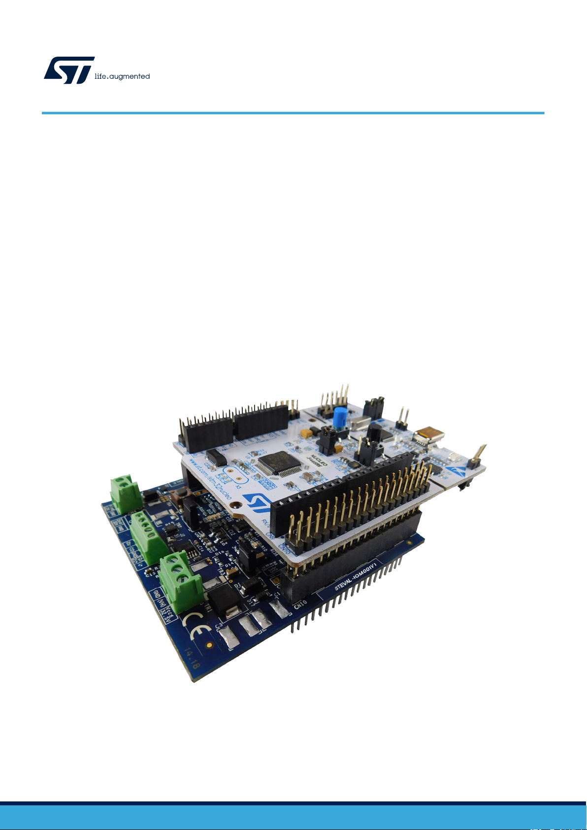
AL-IOM001V1 and the NUCLEO-F446RE boards.
Figure 1. P-NUCLEO-IOM01M1 evaluation pack
UM2421 - Rev 5 - October 2020
For further information contact your local STMicroelectronics sales of
fice.
www.st.com
Page 2
1 Architecture overview
A generic IO-Link system is composed of an IO-Link master and an IO-Link device connected by an unshielded
cable. Normally
system.
The IO-Link master is installed in the control cabinet or, as a remote I/O, directly in the field. It can have several
IO-Link ports (channels): an IO-Link device can be connected to each port, hence, it is a point-to-point
communication and not a fieldbus.
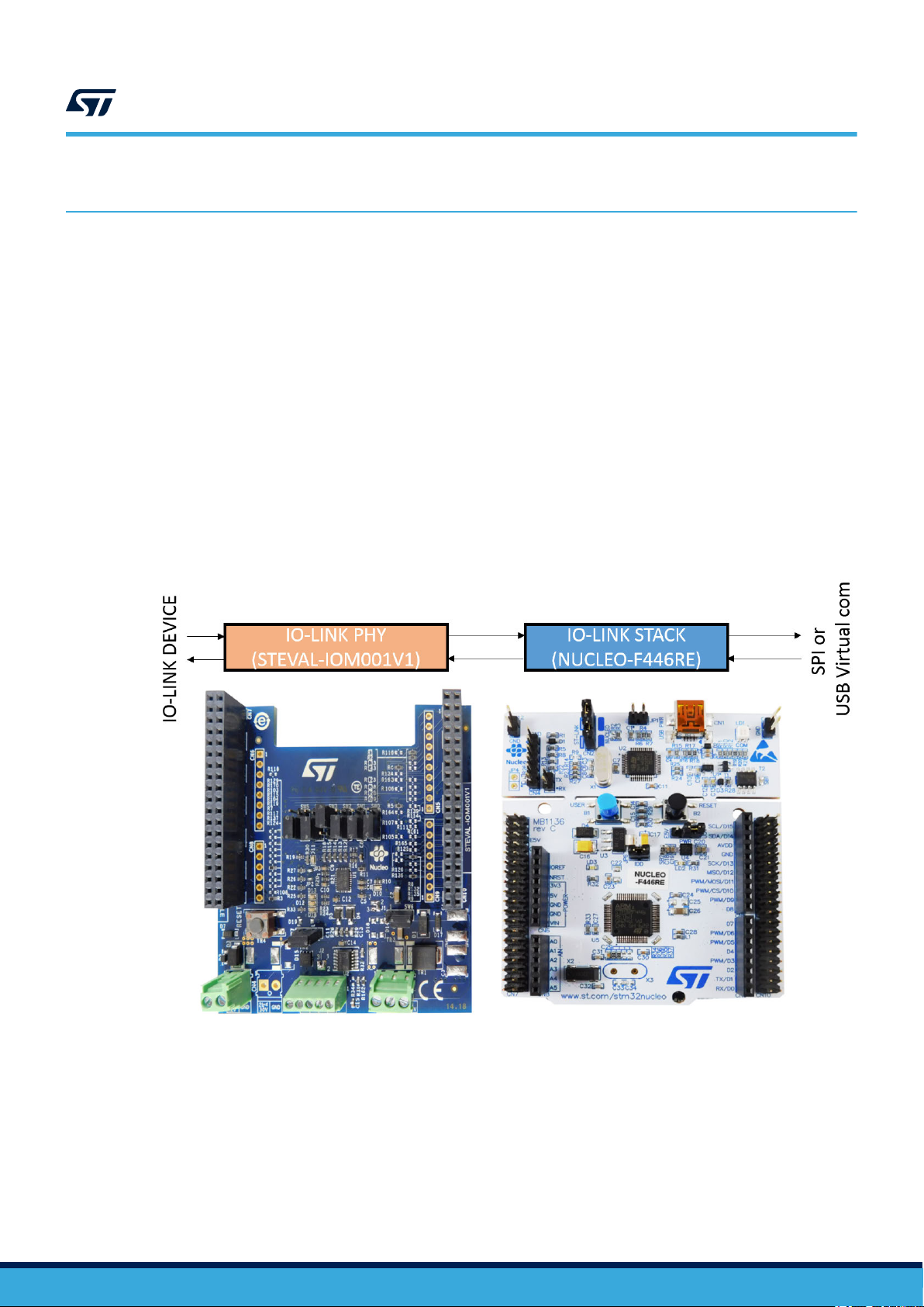
A single port master, as the P-NUCLEO-IOM01M1, can be schematized as the arrangement of two main blocks
(see Figure 2. P-NUCLEO-IOM01M1 block details):
• Control sub-system: the NUCLEO-F446RE board runs the IO-Link stack and firmware accepting user
commands, configuration parameters and controlling the remote IO-Link device. The NUCLEO-F446RE
board provides all digital signals to perform the proper control for single and multi-port (up to 4) IO-Link
master. You can evaluate the tool via the dedicated GUI (IO-Link Control Tool by TeConcept®) or use it as an
IO-Link master bridge accessible from the dedicated SPI interface.
• IO-Link physical: the STEVAL-IOM001V1 mounts the ST transceiver L6360, which interfaces with the
micro-controller by digital interfaces (I²C for status and configuration; UART for IO-Link data transfer) and
the IO-Link device by the IO-Link interface (type A or type B as defined by the standard).
, the IO-Link master is the connection point between the IO-Link device and the automation
UM2421
Architecture overview
Figure 2. P-NUCLEO-IOM01M1 block details
UM2421 - Rev 5
page 2/19
Page 3

2 Getting started
2.1 Hardware requirements
To evaluate the system, the hardware requirements are:
a P-NUCLEO-IOM01M1 (STEVAL-IOM001V1 plus NUCLEO-F446RE)
•
• a power supply (18-32.5 V)
• a USB cable (type A to mini-B)
• an IO-Link (v1.1) device (e.g. P-NUCLEO-IOD01A1)
• connection cable/wires between IO-Link master and IO-Link device
• a Laptop/PC
The P-NUCLEO-IOM01M1 is a complete single port IO-Link master composed by two application boards
(STEVAL-IOM001V1 and NUCLEO-F446RE) connected via the CN7 and CN10 ST morpho connectors.
A power supply (from 18 to 32.5 V) is necessary to supply the STEVAL-IOM001V1 via the CN1 connector,
whereas the NUCLEO-F446RE can be supplied by connecting its mini-USB port to your PC/Laptop USB port
through a USB type A to mini-B USB cable.
For a full evaluation of the system, an IO-Link device compatible with specification v1.1 (for example, P-NUCLEO-
IOD01A1) is also necessary.
The IO-Link master can be controlled by the IO-Link Control Tool (through USB) of TEConcept, or by the SPI
interface available on CN7: in this case, a SPI master (for example, another STM32 Nucleo board programmed
with Low-Level IO-Link Master Access Demo Application) and the connection wires for SPI signals are necessary
(see also Section 3.3 Development system setup).
UM2421
Getting started
2.2 Software requirements
To complete the system, you need a PC/laptop with:
•
Windows®(version 7 or above)
• STSW-LINK009 driver installed
For system evaluation only:
• IO-Link Control Tool©(property of TEConcept GmbH)
• the IODD file of your IO-Link device
For application development:
• the SPI master control software (Low-Level IO-Link Master Access Demo Application)
2.2.1 Low-Level IO-Link Master Access Demo
The Low-Level IO-Link Master Access Demo application is an example of how to build host application for
controlling the IO-Link. It provides low-level functions which make possible basic communication with IO-Link
master (for example, to change the IO-Link port configuration, to read or write parameters, etc.).
The Low-Level IO-Link Master Access module has its own abstraction layers that run on dif
as Windows, Linux, Cortex-M) and provides different peripherals for the connection with the IO-Link master (such
as SPI, USB Virtual COM port, UART232, etc.).
For details on the control of the IO-Link master from your host application running on an embedded environment,
refer to Figure 9. P-NUCLEO-IOM01M1 development system connections.
ferent platforms (such
UM2421 - Rev 5
page 3/19
Page 4
3 How to build and run the IO-Link master
3.1 Single port system evaluation setup
UM2421
How to build and run the IO-Link master
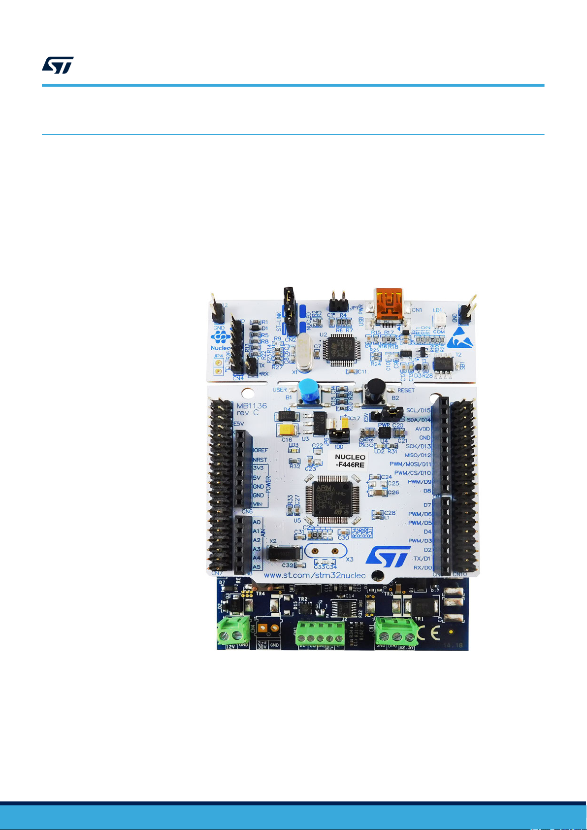
Step 1. Connect the STEV
morpho connectors.
Important:
The STEVAL-IOM001V1 evaluation board must be on the opposite side with respect to the NUCLEO-F446RE board mini-USB
connector
, as shown in the figure below.
Figure 3. STEV
AL-IOM001V1 evaluation board to the NUCLEO-F446RE board through the ST
AL-IOM001V1 connected to NUCLEO-F446RE (P-NUCLEO-IOM01M1 stack)
UM2421 - Rev 5
page 4/19
Page 5
UM2421
Single port system evaluation setup
Step 2. Connect the STEV
pin/signal correspondence.
AL-IOM001V1 to the IO-Link device by screwing cables on CN3, taking care of the
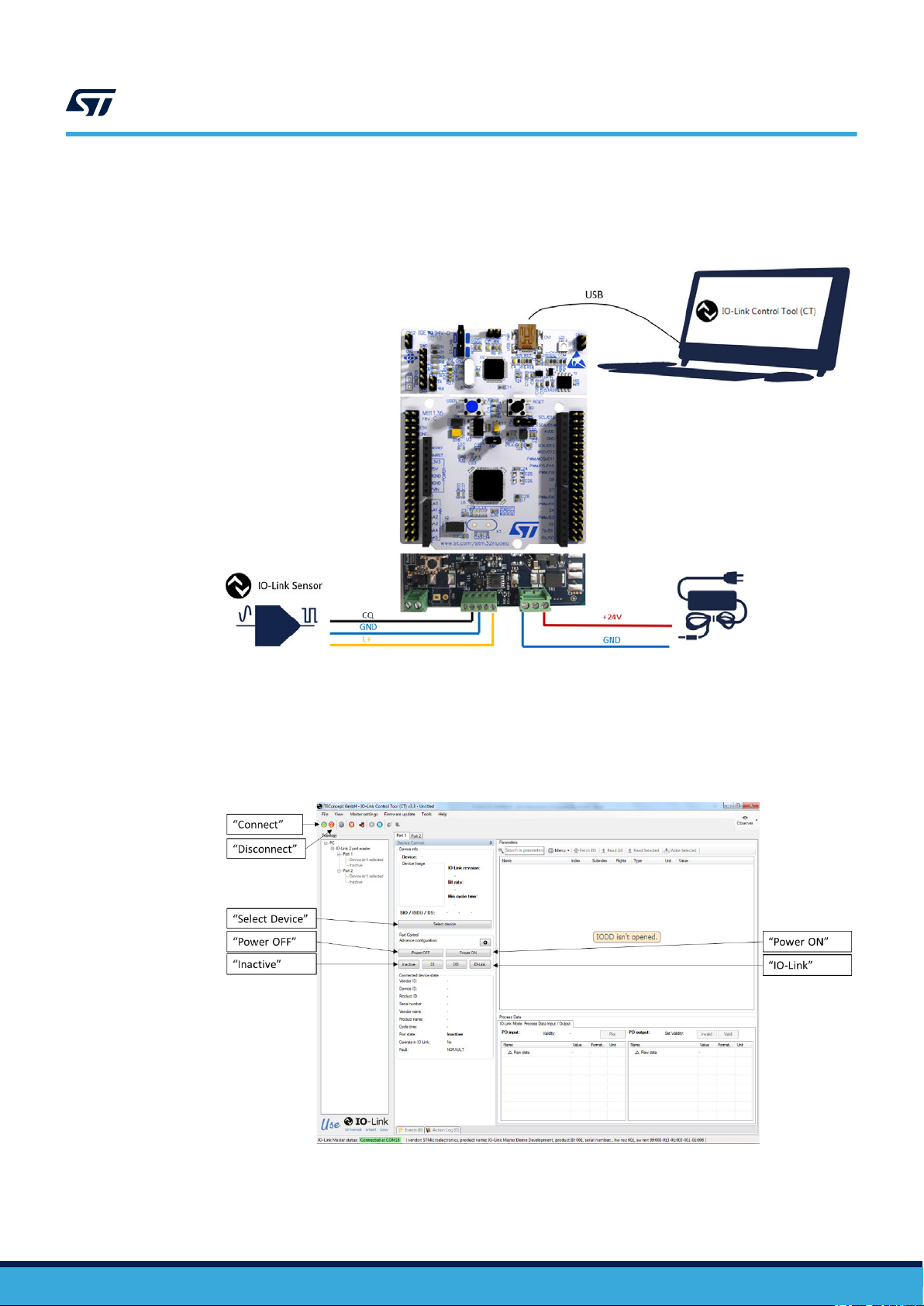
Figure 4. P-NUCLEO-IOM01M1 evaluation system connections
Step 3. Launch the IO-Link Control T
ool (CT) on your laptop/PC.
Step 4. Connect the USB cable between the laptop/PC USB port and the P-NUCLEO-IOM01M1 mini-USB
port.
Step 5. Click on the Control Tool [Connect] button (green icon).
Figure 5. IO-Link Control Tool interface
UM2421 - Rev 5
Step 6. Connect the power supply to the STEV
to Figure 4. P-NUCLEO-IOM01M1 evaluation system connections).
AL-IOM001V1 CN1 connector, taking care of the polarity (refer
page 5/19
Page 6
UM2421
Single port system evaluation setup
Step 7. Activate the power supply connected to the STEV
AL-IOM001V1.
Step 8. Reset the STEVAL-IOM001V1 by clicking the [reset] button.
Step 9. Reset the NUCLEO-F446RE by clicking the [black] button.
The system is now ready to operate and can be controlled by the IO-Link Control Tool.
Step 10. Click on [Inactive] to stop previous data exchange (refer to Figure 5. IO-Link Control Tool interface).
Step 11. Select [Port 1] tab and click on [Power OFF]: this action drives low the ENL+ signal and L+ line. CN3
does not supply the IO-Link device anymore (refer to Figure 5. IO-Link Control Tool interface).
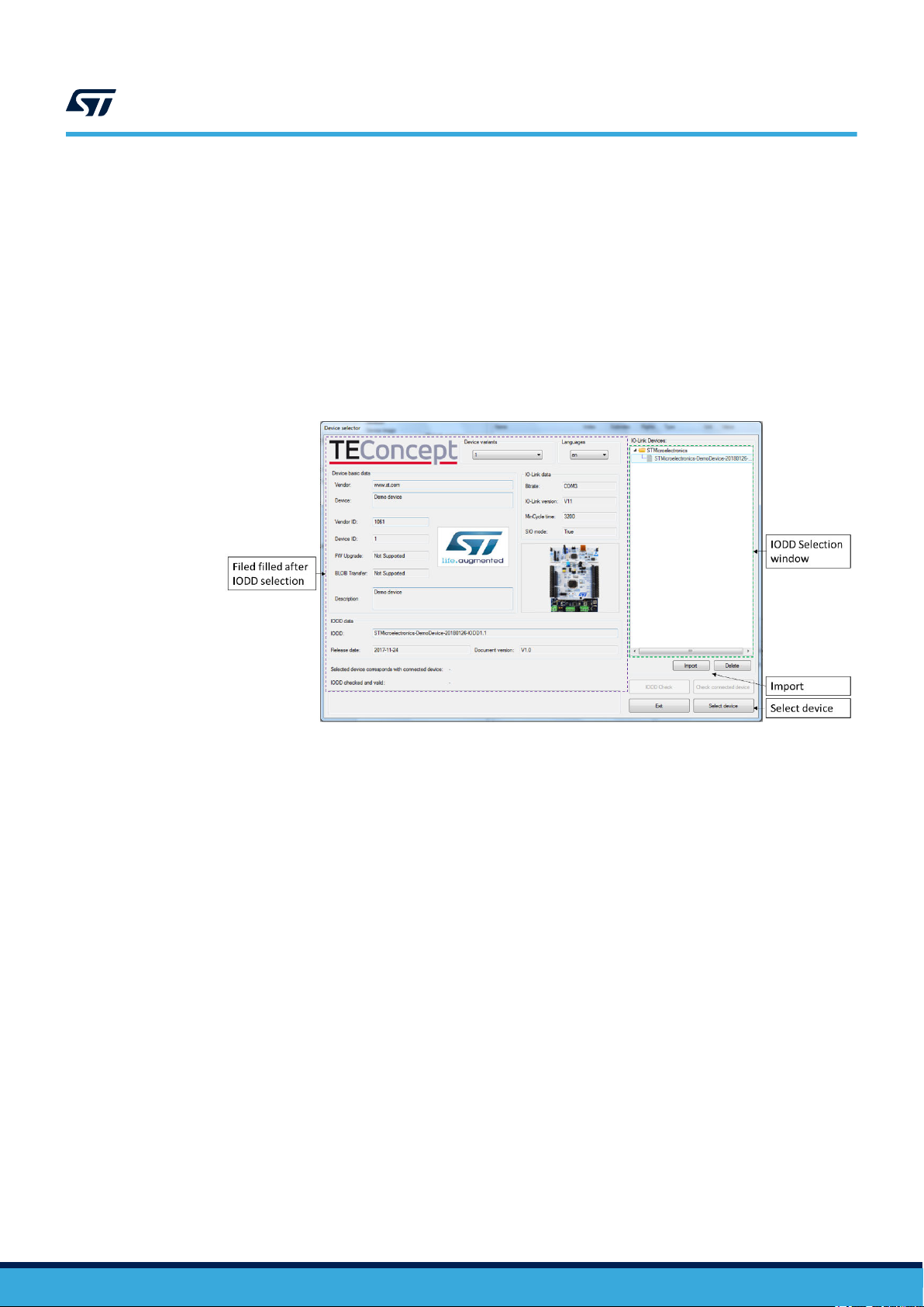
Step 12. Click on [Select Device]: the Device selector window appears.
Figure 6. IO-Link Control Tool - IODD selection
Step 13. Select the IODD XML file of your IO-Link device from the list and click [Select Device].
The Device selector is then closed.
If the IODD files does not appear in the list, click [Import], browse your folders and then click
[Open] to
add the XML file of your IO-Link Device to the list of the Device Selector window.
Step 14. Click on [Power On] (ENL+ is turned ON and the IO-Link device is supplied by L+ line).
Step 15. Click on [IO-Link] to activate the wake-up request and establish communication with the IO-Link
device. The Device Status window shows the connection status (see Figure 7. IO-Link Control Tool -
sensor and data format activators)
Step 16. In the Parameter tab, open the Identification menu and double click on the right side of the Sensor
Activator “var”: a selection window opens to select the sensor to be activated.
If the P-NUCLEO-IOD01A1 is connected, select [All sensors are enabled (30)] and click anywhere
outside the window.
Step 17. Click on the [Sensor Activator] row and then click on the [Write Selected] button to definitively
activate the selection.
Step 18. In the Parameter tab, double click on the right side of the Process Data Layout “var”:
a selection window is open.
Step 19. Select the desired data to display (e.g. “Temperature + Humidity (7)”, if P-NUCLEO-IOD01A1 is used)
and then click anywhere outside the window.
UM2421 - Rev 5
page 6/19
Page 7

UM2421
Single port system evaluation setup
Step 20. Click on the Process Data Layout
activate the selection.
The selected data start to be transferred from IO-Link device to IO-Link master.
Figure 7. IO-Link Control Tool - sensor and data format activators
row and then click on the [Write Selected] button to definitively
The data transferred from the IO-Link device to the master can be plot by the steps below (except if
you are using P-NUCLEO-IOD01A1 and “raw data” were selected).
Step 21. Click on [Plot]
.
A pop-up window appears
Figure 8. IO-Link Control Tool - data plot
Step 22. Edit the time scale according to your preference (e.g. from 600s to 60s).
The plot starts to be filled (sample rate = 1s) with the data sensed by the receiver and received by the
master through IO-Link connection. Click on the [pause] icon to stop plotting.
UM2421 - Rev 5
Step 23. When the system evaluation is completed, click on [Inactive] to stop the data flow.
Step 24. Click on the Control Tool [Power OFF] button to stop supplying the IO-Link device.
page 7/19
Page 8

UM2421
Multi-port evaluation system setup
Step 25. Disconnect the P-NUCLEO-IOM01M1 by clicking on the Control T
power supply and unplugging the mini-USB cable.
3.2 Multi-port evaluation system setup
By default, the STEVAL-IOM001V1 switches and solder bridges are configured to work as an IO-Link single port.
You can stack up to four STEVAL-IOM001V1 evaluation boards below the same NUCLEO-F446RE to create a
quad-port IO-Link master.
To configure the additional ports (from 2 to 4), you have to modify the STEVAL-IOM001V1 configuration according
to the instructions reported in Table 1. IO-Link port configuration and Table 2. I²C address setting. After having
configured the evaluation board, follow the procedure described in Section 3.1 Single port system evaluation
setup for each port (a tab is associated to each IO-Link port).
Table 1. IO-Link port configuration
IO-Link PORT-2
SIGNAL
SOLDER BRIDGE
O UNMOUNT
T
ENCQ R3
INCQ R5 R115 CN8[1] R105 CN9[7] R134 CN10[4]
OUTCQ R9 R119 CN8[2] R139 CN10[6] R109 CN5[2]
ENL+ R4 R114 CN9[8] R124 CN7[35] R135 CN10[34]
RST R8 R108 CN8[5] R128 CN10[16] R138 CN10[14]
OUTIQ
R106
(1)
(I2C address: see T
SOLDER BRIDGE
T
O MOUNT
R143 CN5[6] R123 CN10[12] R133 CN10[2]
R116
(1)
able 4)
CN[pin]
CN10[1]
ool [Disconnect] icon, removing the
IO-Link PORT-3
(I2C address: see Table 4)
SOLDER BRIDGE
TO MOUNT
R126
(1)
CN[pin]
CN10[30]
IO-Link PORT-4
(I2C address: see Table 4)
SOLDER BRIDGE
TO MOUNT
R136
(1)
CN[pin]
CN10[28]
IRQ R7 R117 CN8[4] R107 CN10[24] R137 CN7[37]
L+ON R162 R163 CN5[4] R164 CN10[22] R165 CN10[26]
Modification is only required if OUTIQ is used.
1.
Table 2. I²C address setting
SW2 SW1 SW0 Port address Note
0 0 0 0x00 (default) Available
0 0 1 0x01 Available
0 1 0 0x02 Available
0 1 1 0x03 Available
1 0 0 0x04 Reserved
1 0 1 0x05 Reserved
1 1 0 0x06 Reserved
1 1 1 0x07 Reserved
UM2421 - Rev 5
page 8/19
Page 9

Signal Functionality
ENL+ GPIO (out) controlling the ENL+ pin of L6360 (U1)
ENCQ GPIO (out) controlling the ENCQ pin of L6360 (U1)
INCQ UART (TX) controlling INCQ pin of L6360 (U1)
OUTCQ UART (RX) controlling OUTCQ pin of L6360 (U1)
SCL Serial clock line controlling I²C SCL pin of L6360 (U1)
SDA Serial data line controlling I²C SDA pin of L6360 (U1)
RST GPIO (out) controlling the RST pin of L6360 (U1)
IRQ GPIO (external event) controlling the IRQ pin of L6360 (U1)
OUTIQ Not used by default, it can be configured on a UART (RX) to control the OUTIQ pin of L6360 (U1)
L+_ON GPIO (out) controlling the IN pin of IPS161H (U2)
OL-OFF GPIO (input) controlling the DIAG pin of IPS161H (U2)
3.3 Development system setup
UM2421
Development system setup
Table 3. Digital signal description
The P-NUCLEO-IOM01M1 provides an SPI interface allowing the user to develop his own application and to use
the board as an IO-Link master node. The figure below shows this application architecture.
Figure 9. P-NUCLEO-IOM01M1 development system connections
UM2421 - Rev 5
To control the P-NUCLEO-IOM01M1 by the SPI interface, you need an SPI master peripheral, for example an
STM32 NUCLEO-F746ZG
running the Low-Level IO-Link Master Access Demo Application.
Both Low-Level IO-Link Master Access Demo Application and the API user guide of the SPI are available for free
by signing up to http://www.teconcept.de/en/CloudAccess/.
For wire connections, refer to the table below.
page 9/19
Page 10

UM2421
Development system setup
Table 4. NUCLEO-F446RE and NUCLEO-F746ZG - SPI and PCP
Signal
Connector Pin Port Connector Pin Port
SPI_CLK
SPI_MISO 2 PC11 CN12 13 PA6
SPI_MOSI 3 PC12 CN12 15 PA7
SPI_CS 17 PA15 CN11 32 PA4 SPI chip select pin
PCPDA_RST 4 PD2
GND 8, 19 - CN12 9, 20 - Ground
NUCLEO-F446RE NUCLEO-F746ZG
1 PC10 CN12 11 PA5
CN7
Reserved for High-Level Master Access
A_RST signal-to-pin correspondence
Functionality
SPI Clock signal
SPI MISO signal (PNUCLEO-IOM01M1
implements SPI slave)
SPI MOSI signal (PNUCLEO-IOM01M1
implements SPI slave)
PCPDA reset signal,
module
active only for High-
Level Master Access
module
Note: The P-NUCLEO-IOM01M1 signal levels swing between 0 and 3.3 V (the same levels have to be respected by
the SPI master interface).
UM2421 - Rev 5
page 10/19
Page 11

4 Board status and LEDs
UM2421
Board status and LEDs
The STEV
AL-IOM001V1 mounts different LEDs for the board status.
Table 5. STEVAL-IOM001V1 - LED functions
LED Color Function
D10 Green Turns on when the voltage regulator integrated in the L6360
D11 Red Turns on when the L6360 forces the IRQ pin low
D12 Yellow See T
D13 Yellow See T
D16 Red Turns on when the DIAG pin of IPS161H is activated (open load or fault events)
able 7. P-NUCLEO-IOM01M1 - LED D12 functionality
able 6. P-NUCLEO-IOM01M1 - LED D13 functionality
(VDD pin) is active
Table 6. P-NUCLEO-IOM01M1 - LED D13 functionality
D13 Port status
OFF L+ is not powered (→ IO-Link device is not supplied)
ON L+ is powered (→ IO-Link device is supplied)
Table 7. P-NUCLEO-IOM01M1 - LED D12 functionality
D12 Port status
OFF Port status is INACTIVE
ON Port is running in one of the three operating modes: IO-Link, DI or DO
Blinking 2 Hz Port is in START-UP or PRE-OPERATE state
Blinking 0.5 Hz Port is in FAULT state
UM2421 - Rev 5
page 11/19
Page 12

5 Firmware update
The P-NUCLEO-IOM01M1 evaluation pack is sold with the firmware already flashed, but it is anyway possible to
update the firmware to its latest version using the IO-Link Control T
The procedure below is the only one allowed: any other erase/overwrite of the preloaded stack makes impossible
to restore it.
Step 1. Download the updated firmware from TEConcept cloud (http://www.teconcept.de/en/CloudAccess/).
Step 2. Launch the IO-Link Control Tool on your laptop/PC.
Step 3. Connect the USB cable between laptop/PC and the P-NUCLEO-IOM01M1.
Step 4. Click on the [Connect] green icon of the CT (see Figure 5. IO-Link Control Tool interface).
Step 5. Click on [Firmware update]>[Master firmware update/change].
The firmware update window appears.
UM2421
Firmware update
ool.
Figure 10. Firmware update window - ready to load the firmware
UM2421 - Rev 5
page 12/19
Page 13

Step 6. Click [Open] and browse your folders to select the firmware to flash.
The Firmware update window is now ready to flash the new firmware.
UM2421
Firmware update
Figure 1
1. Firmware update window - ready to flash the firmware
Note:
Step 7. Click on [Update] to start the flashing process.
Do not tick the Without checking flag.
When the flashing procedure finishes, the firmware is automatically reset and the P-NUCLEOIOM01M1 is disconnected by the Control Tool.
Step 8. Click on the Control Tool green icon to connect again the P-NUCLEO-IOM01M1.
The system is now running the updated firmware and ready to work.
UM2421 - Rev 5
page 13/19
Page 14

Appendix A References
UM2421
References
The following resources are freely available on www
1. L6360 datasheet
2. IPS161H datasheet
3. P-NUCLEO-IOM01M1 data brief
4. P-NUCLEO-IOM01M1 quick start guide
5. STEVAL-IOM001V1 data brief
6. STEVAL-IOM001V1 user manual
7. P-NUCLEO-IOD01A1 data brief
8. P-NUCLEO-IOD01A1 quick start guide
9. P-NUCLEO-IOD01A1 user manual
The following resources are all freely available on TEConcept cloud (http://www.teconcept.de/en/CloudAccess/):
1. IO-Link Control Tool installation file
2. IO-Link Master encrypted firmware
3. IO-Link-Master-Access-Low-Level source code
4. IO-Link-Master-Access-Low-Level user guide
5. IO-Link-Master-Access-Low-Level SPI access description
.st.com.
UM2421 - Rev 5
page 14/19
Page 15

Revision history
Date Revision Changes
25-Jun-2018 1 Initial release.
04-Jul-2018 2 Removed schematic diagrams and bill of materials.
30-Jul-2018 3
02-Mar-2020 4 Updated introduction and Section 5 Firmware update.
27-Oct-2020 5
UM2421
able 8. Document revision history
T
Updated Section A References.
Minot text edits.
Updated Section 3.1 Single port system evaluation setup and Section 3.3 Development system
setup.
UM2421 - Rev 5
page 15/19
Page 16

UM2421
Contents
Contents
1 Architecture overview .............................................................2
2 Getting started ....................................................................3
2.1 Hardware requirements .........................................................3
2.2 Software requirements ..........................................................3
2.2.1 Low-Level IO-Link Master Access Demo.......................................3
3 How to build and run the IO-Link master ...........................................4
3.1 Single port system evaluation setup ...............................................4
3.2 Multi-port evaluation system setup ................................................8
3.3 Development system setup ......................................................9
4 Board status and LEDs ...........................................................1
5 Firmware update..................................................................12
Appendix A References ..............................................................14
Revision history .......................................................................15
1
UM2421 - Rev 5
page 16/19
Page 17

UM2421
List of tables
List of tables
able 1. IO-Link port configuration .............................................................. 8
T
Table 2. I²C address setting...................................................................8
Table 3. Digital signal description ...............................................................9
Table 4. NUCLEO-F446RE and NUCLEO-F746ZG - SPI and PCPA_RST signal-to-pin correspondence ............. 10
Table 5. STEVAL-IOM001V1 - LED functions...................................................... 11
Table 6. P-NUCLEO-IOM01M1 - LED D13 functionality............................................... 11
Table 7. P-NUCLEO-IOM01M1 - LED D12 functionality............................................... 11
Table 8. Document revision history ............................................................. 15
UM2421 - Rev 5
page 17/19
Page 18

UM2421
List of figures
List of figures
Figure 1. P-NUCLEO-IOM01M1 evaluation pack ...................................................1
Figure 2. P-NUCLEO-IOM01M1 block details ......................................................2
Figure 3. STEV
Figure 4. P-NUCLEO-IOM01M1 evaluation system connections .........................................5
Figure 5. IO-Link Control Tool interface ..........................................................5
Figure 6. IO-Link Control Tool - IODD selection ....................................................6
Figure 7. IO-Link Control Tool - sensor and data format activators........................................7
Figure 8. IO-Link Control Tool - data plot .........................................................7
Figure 9. P-NUCLEO-IOM01M1 development system connections .......................................9
Figure 10. Firmware update window - ready to load the firmware ........................................ 12
Figure 11. Firmware update window - ready to flash the firmware........................................ 13
AL-IOM001V1 connected to NUCLEO-F446RE (P-NUCLEO-IOM01M1 stack) ....................4
UM2421 - Rev 5
page 18/19
Page 19

UM2421
IMPORTANT NOTICE – PLEASE READ CAREFULLY
STMicroelectronics NV and its subsidiaries (“ST”) reserve the right to make changes, corrections, enhancements, modifications, and improvements to ST
products and/or to this document at any time without notice. Purchasers should obtain the latest relevant information on ST products before placing orders. ST
products are sold pursuant to ST’
Purchasers are solely responsible for the choice, selection, and use of ST products and ST assumes no liability for application assistance or the design of
Purchasers’ products.
No license, express or implied, to any intellectual property right is granted by ST herein.
Resale of ST products with provisions different from the information set forth herein shall void any warranty granted by ST for such product.
ST and the ST logo are trademarks of ST. For additional information about ST trademarks, please refer to www
names are the property of their respective owners.
Information in this document supersedes and replaces information previously supplied in any prior versions of this document.
s terms and conditions of sale in place at the time of order acknowledgement.
.st.com/trademarks. All other product or service
© 2020 STMicroelectronics – All rights reserved
UM2421 - Rev 5
page 19/19
 Loading...