

STMicroelectronics STM32, MB1319, NUCLEOL412RB-P, NUCLEO-L433RC-P, NUCLEO-L452RE-P User Manual
UM2206
User manual
STM32 Nucleo-64-P boards (MB1319)
Introduction
The STM32 Nucleo-64-P boards based on the MB1319 reference board (NUCLEOL412RB-P, NUCLEO-L433RC-P and NUCLEO-L452RE-P) provide an affordable and
flexible way for users to try out new concepts and build prototypes with the STM32
microcontroller and the external SMPS (switched mode power supply), which provides
various combinations of performance, power consumption and features.
®
ARDUINO
expanding the functionality of the Nucleo open development platform with a wide choice of
specialized shields.
The STM32 Nucleo-64-P boards do not require any separate probe, as they integrate the
ST-LINK/V2-1 debugger/programmer. The STM32 Nucleo-64-P boards come with the
prehensive free STM32 software libraries and examples that are available with the
com
STM32Cube package.
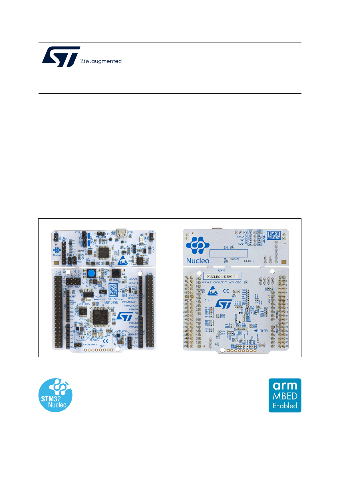
Figure 1. Nucleo-64-P board (top view) Figure 2. Nucleo-64-P board (bottom view)
Uno V3 connectivity and ST morpho headers provide an easy means of
Pictures are not contractual.
December 2020 UM2206 Rev 5 1/50
www.st.com
1

Contents UM2206
Contents
1 Features . . . . . . . . . . . . . . . . . . . . . . . . . . . . . . . . . . . . . . . . . . . . . . . . . . . 7
2 Ordering information . . . . . . . . . . . . . . . . . . . . . . . . . . . . . . . . . . . . . . . . 8
2.1 Codification . . . . . . . . . . . . . . . . . . . . . . . . . . . . . . . . . . . . . . . . . . . . . . . . . 8
3 Development environment . . . . . . . . . . . . . . . . . . . . . . . . . . . . . . . . . . . . 9
3.1 System requirements . . . . . . . . . . . . . . . . . . . . . . . . . . . . . . . . . . . . . . . . . 9
3.2 Development toolchains . . . . . . . . . . . . . . . . . . . . . . . . . . . . . . . . . . . . . . . 9
3.3 Demonstration software . . . . . . . . . . . . . . . . . . . . . . . . . . . . . . . . . . . . . . . 9
4 Conventions . . . . . . . . . . . . . . . . . . . . . . . . . . . . . . . . . . . . . . . . . . . . . . . 10
5 Quick start . . . . . . . . . . . . . . . . . . . . . . . . . . . . . . . . . . . . . . . . . . . . . . . . 11
5.1 Getting started . . . . . . . . . . . . . . . . . . . . . . . . . . . . . . . . . . . . . . . . . . . . . .11
6 Hardware layout and configuration . . . . . . . . . . . . . . . . . . . . . . . . . . . . 12
6.1 STM32 Nucleo-64-P board layout . . . . . . . . . . . . . . . . . . . . . . . . . . . . . . 13
6.2 STM32 Nucleo-64-P board mechanical drawing . . . . . . . . . . . . . . . . . . . 15
6.2.1 Default board configuration . . . . . . . . . . . . . . . . . . . . . . . . . . . . . . . . . . 15
6.3 Cuttable PCB . . . . . . . . . . . . . . . . . . . . . . . . . . . . . . . . . . . . . . . . . . . . . . 16
6.4 Embedded ST-LINK/V2-1 . . . . . . . . . . . . . . . . . . . . . . . . . . . . . . . . . . . . . 16
6.4.1 Drivers . . . . . . . . . . . . . . . . . . . . . . . . . . . . . . . . . . . . . . . . . . . . . . . . . . 17
6.4.2 ST-LINK/V2-1 firmware upgrade . . . . . . . . . . . . . . . . . . . . . . . . . . . . . . 17
6.4.3 Using the ST-LINK/V2-1 to program/debug the STM32 . . . . . . . . . . . . 18
6.4.4 Using the ST-LINK/V2-1 to program/debug an external STM32
application. . . . . . . . . . . . . . . . . . . . . . . . . . . . . . . . . . . . . . . . . . . . . . . . 18
6.5 Power supply and power selection . . . . . . . . . . . . . . . . . . . . . . . . . . . . . . 20
6.5.1 External Power supply input . . . . . . . . . . . . . . . . . . . . . . . . . . . . . . . . . 20
6.5.2 External power supply output . . . . . . . . . . . . . . . . . . . . . . . . . . . . . . . . 25
6.5.3 SMPS power supply . . . . . . . . . . . . . . . . . . . . . . . . . . . . . . . . . . . . . . . 25
6.6 Programming/debugging when the power supply is not from
ST-LINK (5V_ST_link) . . . . . . . . . . . . . . . . . . . . . . . . . . . . . . . . . . . . . . . 26
6.7 OSC clock sources . . . . . . . . . . . . . . . . . . . . . . . . . . . . . . . . . . . . . . . . . . 26
6.7.1 LSE: OSC 32 KHz clock supply . . . . . . . . . . . . . . . . . . . . . . . . . . . . . . . 26
2/50 UM2206 Rev 5

UM2206 Contents
6.7.2 OSC clock supply . . . . . . . . . . . . . . . . . . . . . . . . . . . . . . . . . . . . . . . . . 27
6.8 Reset sources . . . . . . . . . . . . . . . . . . . . . . . . . . . . . . . . . . . . . . . . . . . . . 28
6.9 Virtual COM port: LPUART1/USART1 . . . . . . . . . . . . . . . . . . . . . . . . . . . 28
6.10 LEDs . . . . . . . . . . . . . . . . . . . . . . . . . . . . . . . . . . . . . . . . . . . . . . . . . . . . 28
6.11 Push buttons . . . . . . . . . . . . . . . . . . . . . . . . . . . . . . . . . . . . . . . . . . . . . . 29
6.12 IDD measurement . . . . . . . . . . . . . . . . . . . . . . . . . . . . . . . . . . . . . . . . . . 29
6.13 Jumper configuration . . . . . . . . . . . . . . . . . . . . . . . . . . . . . . . . . . . . . . . . 30
6.14 Configuration of the solder bridges . . . . . . . . . . . . . . . . . . . . . . . . . . . . . 30
7 Connectors . . . . . . . . . . . . . . . . . . . . . . . . . . . . . . . . . . . . . . . . . . . . . . . 35
7.1 USB Micro-B connector CN1 . . . . . . . . . . . . . . . . . . . . . . . . . . . . . . . . . . 35
7.2 ARDUINO
7.3 ST morpho connectors CN5 and CN6 . . . . . . . . . . . . . . . . . . . . . . . . . . . 39
7.4 External power connector . . . . . . . . . . . . . . . . . . . . . . . . . . . . . . . . . . . . . 40
®
Uno V3 connectors . . . . . . . . . . . . . . . . . . . . . . . . . . . . . . . . 36
8 STM32 Nucleo-64-P board information . . . . . . . . . . . . . . . . . . . . . . . . . 42
8.1 Product marking . . . . . . . . . . . . . . . . . . . . . . . . . . . . . . . . . . . . . . . . . . . . 42
8.2 Board revision history . . . . . . . . . . . . . . . . . . . . . . . . . . . . . . . . . . . . . . . . 42
8.2.1 MB1319 revision B02 . . . . . . . . . . . . . . . . . . . . . . . . . . . . . . . . . . . . . . . 42
8.2.2 MB1319 revision C01 . . . . . . . . . . . . . . . . . . . . . . . . . . . . . . . . . . . . . . 42
8.3 Known limitations . . . . . . . . . . . . . . . . . . . . . . . . . . . . . . . . . . . . . . . . . . . 42
Appendix A NUCLEO-L412RB-P, NUCLEO-L433RC-P and NUCLEO-L452RE-P
I/O assignment . . . . . . . . . . . . . . . . . . . . . . . . . . . . . . . . . . . . . . . . . . 43
Appendix B Federal Communications Commission (FCC)
and ISED Canada Compliance . . . . . . . . . . . . . . . . . . . . . . . . . . . . . 46
B.1 FCC Compliance Statement . . . . . . . . . . . . . . . . . . . . . . . . . . . . . . . . . . . 46
B.1.1 Part 15.19 . . . . . . . . . . . . . . . . . . . . . . . . . . . . . . . . . . . . . . . . . . . . . . . . 46
B.1.2 Part 15.21 . . . . . . . . . . . . . . . . . . . . . . . . . . . . . . . . . . . . . . . . . . . . . . . . 46
B.1.3 Part 15.105 . . . . . . . . . . . . . . . . . . . . . . . . . . . . . . . . . . . . . . . . . . . . . . . 46
B.2 ISED Canada Compliance Statement. . . . . . . . . . . . . . . . . . . . . . . . . . . . 47
B.2.1 Compliance Statement . . . . . . . . . . . . . . . . . . . . . . . . . . . . . . . . . . . . . . 47
B.2.2 Déclaration de conformité. . . . . . . . . . . . . . . . . . . . . . . . . . . . . . . . . . . . 47
Appendix C CE / RED . . . . . . . . . . . . . . . . . . . . . . . . . . . . . . . . . . . . . . . . . . . . . . . 48
UM2206 Rev 5 3/50
4

Contents UM2206
C.1 EN55032 / CISPR32 . . . . . . . . . . . . . . . . . . . . . . . . . . . . . . . . . . . . . . . . . 48
Revision history . . . . . . . . . . . . . . . . . . . . . . . . . . . . . . . . . . . . . . . . . . . . . . . . . . . . 49
4/50 UM2206 Rev 5

UM2206 List of tables
List of tables
Table 1. Ordering information . . . . . . . . . . . . . . . . . . . . . . . . . . . . . . . . . . . . . . . . . . . . . . . . . . . . . . . 8
Table 2. Codification explanation . . . . . . . . . . . . . . . . . . . . . . . . . . . . . . . . . . . . . . . . . . . . . . . . . . . . 8
Table 3. ON/OFF convention . . . . . . . . . . . . . . . . . . . . . . . . . . . . . . . . . . . . . . . . . . . . . . . . . . . . . . 10
Table 4. Default jumper settings . . . . . . . . . . . . . . . . . . . . . . . . . . . . . . . . . . . . . . . . . . . . . . . . . . . . 16
Table 5. ST-LINK jumper configuration . . . . . . . . . . . . . . . . . . . . . . . . . . . . . . . . . . . . . . . . . . . . . . 17
Table 6. Debug connector SWD . . . . . . . . . . . . . . . . . . . . . . . . . . . . . . . . . . . . . . . . . . . . . . . . . . . . 19
Table 7. Power supply capabilities . . . . . . . . . . . . . . . . . . . . . . . . . . . . . . . . . . . . . . . . . . . . . . . . . . 20
Table 8. SB9 configurations . . . . . . . . . . . . . . . . . . . . . . . . . . . . . . . . . . . . . . . . . . . . . . . . . . . . . . . 24
Table 9. LPUART1 connection . . . . . . . . . . . . . . . . . . . . . . . . . . . . . . . . . . . . . . . . . . . . . . . . . . . . . 28
Table 10. USART1 connection . . . . . . . . . . . . . . . . . . . . . . . . . . . . . . . . . . . . . . . . . . . . . . . . . . . . . . 28
Table 11. Jumper settings . . . . . . . . . . . . . . . . . . . . . . . . . . . . . . . . . . . . . . . . . . . . . . . . . . . . . . . . . 30
Table 12. Solder bridge configurations and settings. . . . . . . . . . . . . . . . . . . . . . . . . . . . . . . . . . . . . . 31
Table 13. USB Micro-B pinout . . . . . . . . . . . . . . . . . . . . . . . . . . . . . . . . . . . . . . . . . . . . . . . . . . . . . . 35
Table 14. ARDUINO
Table 15. External power connector pinout . . . . . . . . . . . . . . . . . . . . . . . . . . . . . . . . . . . . . . . . . . . . 41
Table 16. NUCLEO-L412RB-P, NUCLEO-L433RC-P and NUCLEO-L452RE-P
I/O assignment . . . . . . . . . . . . . . . . . . . . . . . . . . . . . . . . . . . . . . . . . . . . . . . . . . . . . . . . . . 43
Table 17. Document revision history . . . . . . . . . . . . . . . . . . . . . . . . . . . . . . . . . . . . . . . . . . . . . . . . . 49
®
connector pinout . . . . . . . . . . . . . . . . . . . . . . . . . . . . . . . . . . . . . . . . . . . . . . . 37
UM2206 Rev 5 5/50
5

List of figures UM2206
List of figures
Figure 1. Nucleo-64-P board (top view) . . . . . . . . . . . . . . . . . . . . . . . . . . . . . . . . . . . . . . . . . . . . . . . . 1
Figure 2. Nucleo-64-P board (bottom view) . . . . . . . . . . . . . . . . . . . . . . . . . . . . . . . . . . . . . . . . . . . . . 1
Figure 3. Hardware block diagram. . . . . . . . . . . . . . . . . . . . . . . . . . . . . . . . . . . . . . . . . . . . . . . . . . . 12
Figure 4. STM32 Nucleo-64-P board top layout . . . . . . . . . . . . . . . . . . . . . . . . . . . . . . . . . . . . . . . . 13
Figure 5. STM32 Nucleo-64-P board bottom layout . . . . . . . . . . . . . . . . . . . . . . . . . . . . . . . . . . . . . 14
Figure 6. STM32 Nucleo-64 -P board mechanical drawing . . . . . . . . . . . . . . . . . . . . . . . . . . . . . . . . 15
Figure 7. USB composite device . . . . . . . . . . . . . . . . . . . . . . . . . . . . . . . . . . . . . . . . . . . . . . . . . . . . 17
Figure 8. ST-LINK debugger: jumper configuration for on-board MCU . . . . . . . . . . . . . . . . . . . . . . . 18
Figure 9. ST-LINK debugger: jumper configuration for external MCU . . . . . . . . . . . . . . . . . . . . . . . . 19
Figure 10. JP5[1-2]: 5V_STL power source. . . . . . . . . . . . . . . . . . . . . . . . . . . . . . . . . . . . . . . . . . . . . 21
Figure 11. JP5[3-4]: 5V_VIN power source . . . . . . . . . . . . . . . . . . . . . . . . . . . . . . . . . . . . . . . . . . . . . 22
Figure 12. JP5[5-6]: E5V power source . . . . . . . . . . . . . . . . . . . . . . . . . . . . . . . . . . . . . . . . . . . . . . . . 23
Figure 13. JP6[7-8]: 5V_USB_CHG power source . . . . . . . . . . . . . . . . . . . . . . . . . . . . . . . . . . . . . . . 24
Figure 14. USB Micro-B connector CN1 (front view) . . . . . . . . . . . . . . . . . . . . . . . . . . . . . . . . . . . . . . 35
Figure 15. ARDUINO
Figure 16. ARDUINO
Figure 17. ST morpho connector . . . . . . . . . . . . . . . . . . . . . . . . . . . . . . . . . . . . . . . . . . . . . . . . . . . . . 39
Figure 18. ST morpho connector pinout . . . . . . . . . . . . . . . . . . . . . . . . . . . . . . . . . . . . . . . . . . . . . . . 40
Figure 19. External power connector . . . . . . . . . . . . . . . . . . . . . . . . . . . . . . . . . . . . . . . . . . . . . . . . . . 41
®
connectors. . . . . . . . . . . . . . . . . . . . . . . . . . . . . . . . . . . . . . . . . . . . . . . . . . . . 36
®
connector pinout . . . . . . . . . . . . . . . . . . . . . . . . . . . . . . . . . . . . . . . . . . . . . . . 37
6/50 UM2206 Rev 5

UM2206 Features
1 Features
• Common features
– STM32 microcontroller in LQFP64 package
– SMPS: significantly reduces power consumption in Run mode
– 32.768 kHz LSE crystal oscillator
– One user LED shared with ARDUINO
– Two push-buttons: USER and RESET
– ARDUINO
®
Uno V3 expansion connector
– ST morpho expansion connector
– External SMPS experimentation dedicated connector
– Flexible board power supply: ST-LINK/V2-1 USB V
– On-board ST-LINK/V2-1 debugger/programmer with USB re-enumeration
capability: mass storage, Virtual COM port and debug port
– Comprehensive free software libraries and examples available with the
STM32Cube package
– Support of a wide choice of Integrated Development Environments (IDEs) including
IAR Embedded Workbench
®
, MDK-ARM and STM32CubeIDE
• Board-specific feature
–Arm
®
Mbed Enabled™
(a)
compliant
®
or external sources
BUS
a. Arm and Mbed are registered trademarks or trademarks of Arm Limited (or its subsidiaries) in the US and
or elsewhere.
UM2206 Rev 5 7/50
49
Ordering information UM2206
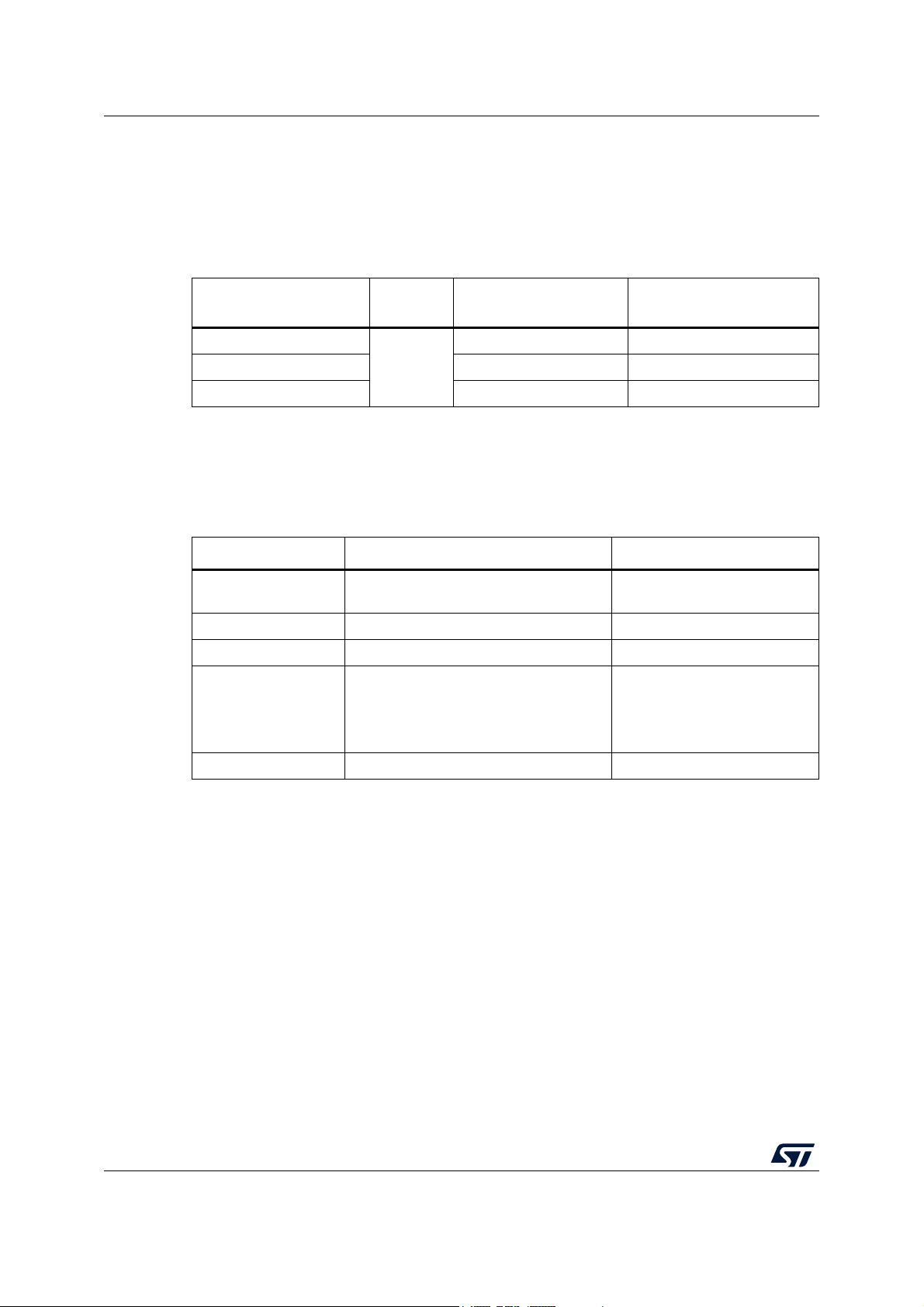
2 Ordering information
To order an STM32 Nucleo-64-P board, refer to, refer to Table 1. Additional information is
available from the datasheet and reference manual of the target STM32.
Table 1. Ordering information
Order code
NUCLEO-L412RB-P
NUCLEO-L433RC-P STM32L433RCT6PU Arm
NUCLEO-L452RE-P STM32L452RET6PU -
2.1 Codification
The meaning of the codification is explained in Tabl e 2.
NUCLEO-XXYYRT-P Description Example: NUCLEO-L452RE-P
XX
YY MCU product line in the series STM32L452
R STM32 package pin count 64 pins
T
-P STM32 has external SMPS function External SMPS
Board
reference
MB1319
Target STM32 Differentiating features
STM32L412RBT6PU -
Table 2. Codification explanation
MCU series in STM32 32-bit Arm Cortex
MCUs
STM32 Flash memory size:
– B for 128 Kbytes
– C for 256 Kbytes
– E for 512 Kbytes
®
Mbed Enabled™
STM32L4 Series
512 Kbytes
8/50 UM2206 Rev 5

UM2206 Development environment
3 Development environment
3.1 System requirements
• Windows® OS (7, 8 and 10), Linux® 64-bit or macOS
• USB Type-A or USB Type-C® to Micro-B cable
3.2 Development toolchains
• IAR Systems® - IAR Embedded Workbench
• Keil® - MDK-ARM
(c)
• STMicroelectronics - STM32CubeIDE
• Arm
®
Mbed™ online
(d)
(see mbed.org)
3.3 Demonstration software
The demonstration software, included in the STM32Cube MCU Package corresponding to
the on-board microcontroller, is preloaded in the STM32 Flash memory for easy
demonstration of the device peripherals in standalone mode. The latest versions of the
demonstration source code and associated documentation can be downloaded from the
www.st.com/stm32nucleo webpage.
®(c)
®(a) (b)
a. macOS® is a trademark of Apple Inc. registered in the U.S. and other countries.
b. All other trademarks are the property of their respective owners.
®
c. On Windows
d. Refer to the www.mbed.com website and to the “Ordering information” section to determine which order
codes are supported.
only.
UM2206 Rev 5 9/50
49
Conventions UM2206
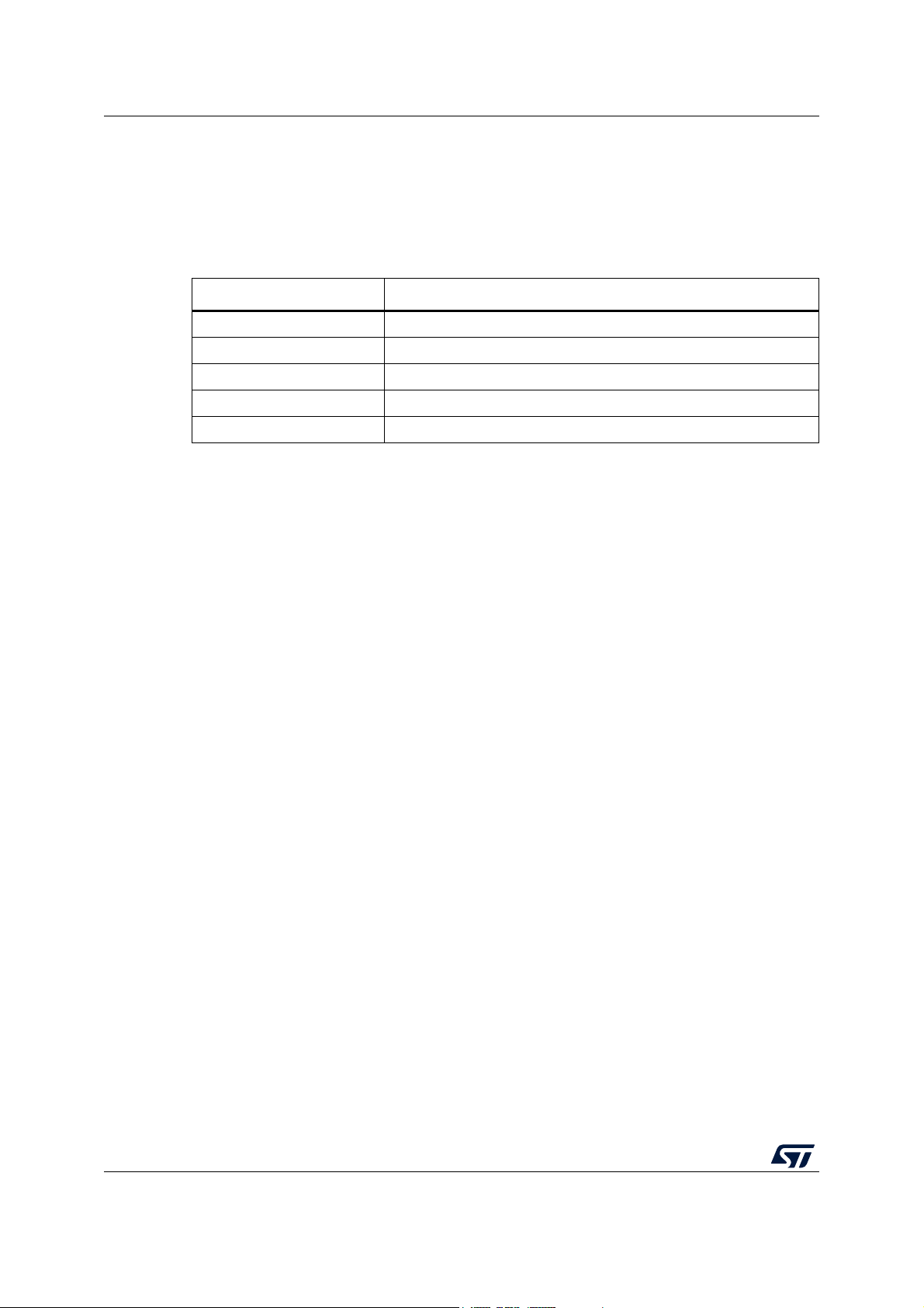
4 Conventions
Tab le 3 provides the conventions used for the ON and OFF settings in the present
document.
Convention Definition
Jumper JPx ON Jumper fitted
Jumper JPx OFF Jumper not fitted
Jumper JPx [1-2] Jumper should be fitted between Pin 1 and Pin 2
Solder bridge SBx ON SBx connections closed by 0 ohm resistor
Solder bridge SBx OFF SBx connections left open
In this document the references for all information that is common to all sale types, are
“STM32 Nucleo-64-P board” and “STM32 Nucleo-64-P boards”.
Table 3. ON/OFF convention
10/50 UM2206 Rev 5

UM2206 Quick start
5 Quick start
This section describes how to start a development quickly using the STM32 Nucleo-64-P
board.
Before installing and using the product, accept the Evaluation Product License Agreement
from the www.st.com/epla webpage.
5.1 Getting started
The STM32 Nucleo-64-P board is a low-cost and easy-to-use development kit to quickly
evaluate and start a development with an STM32 microcontroller in QFP64 package. To
start using this board, follow the steps below:
1. Check the jumper position on the board, as shown in Table 4: Default jumper settings.
2. For a correct identification of all device interfaces from the host PC, install the Nucleo
USB driver available on the www.st.com/stm32nucleo webpage, prior to connecting the
board.
3. To power the board connect the Nucleo-64-P board to a PC with a USB Type-A or USB
Type-C
(5
4. Press user button B1 (blue).
5. Observe that the blinking frequency of the three green LEDs LD4 changes, by clicking
on the button B1.
6. The software demonstration and the several software examples, that allow the user to
use the Nucleo features, are available at the www.st.com/stm32nucleo webpage.
7. Develop an application using the available examples.
®
to Micro-B cable through USB connector CN1. As a result the green LED LD3
V PWR) lights up, LD1 (COM) and green LED LD4 blink.
UM2206 Rev 5 11/50
49
Hardware layout and configuration UM2206
ST-LINK/V2-1 Part
STM32 microcontroller
OSC_32
SWD
VDD_MCU
3.3V / 1.8V
32 KHz
crystal
VCP
UART
GPIO
GPIO
LED
GPIO
Embedded
ST-LINK/V2-1
SWD
SWD
VCP
UART
USB Micro- B
connector
B1
User
B2
Reset
ARDUINO
®
ST morpho
GPIO
ARDUINO
®
ST morpho
5 V
PWR SEL
5 V
LED
VDD_1V2
Ext PWR
Jumper
JP
nRST
VCP
JP STL
nRST
COM
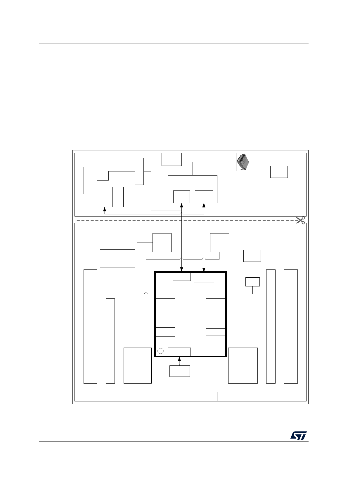
6 Hardware layout and configuration
The STM32 Nucleo-64-P board is designed around the STM32 microcontrollers in a
64-pins LQFP package.
Figure 3 illustrates the connection between the STM32 and the peripherals (ST-LINK/V2-1,
push-buttons, LEDs, ARDUINO® Uno V3 connector and ST morpho connectors).
Figure 4 and Figure 5 show the location of these features on the STM32 Nucleo-64-P
board.
The mechanical dimensions of the board are shown in Figure 6.
Figure 3. Hardware block diagram
12/50 UM2206 Rev 5
UM2206 Hardware layout and configuration
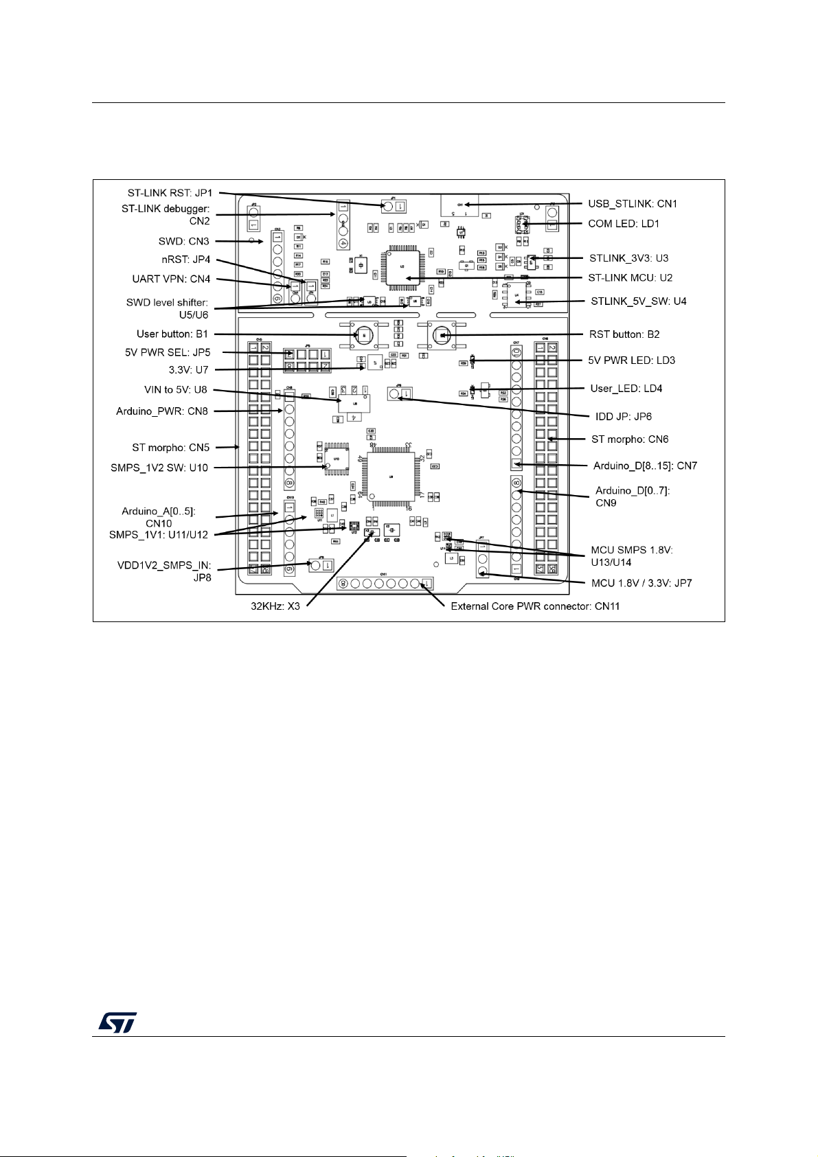
6.1 STM32 Nucleo-64-P board layout
Figure 4. STM32 Nucleo-64-P board top layout
UM2206 Rev 5 13/50
49
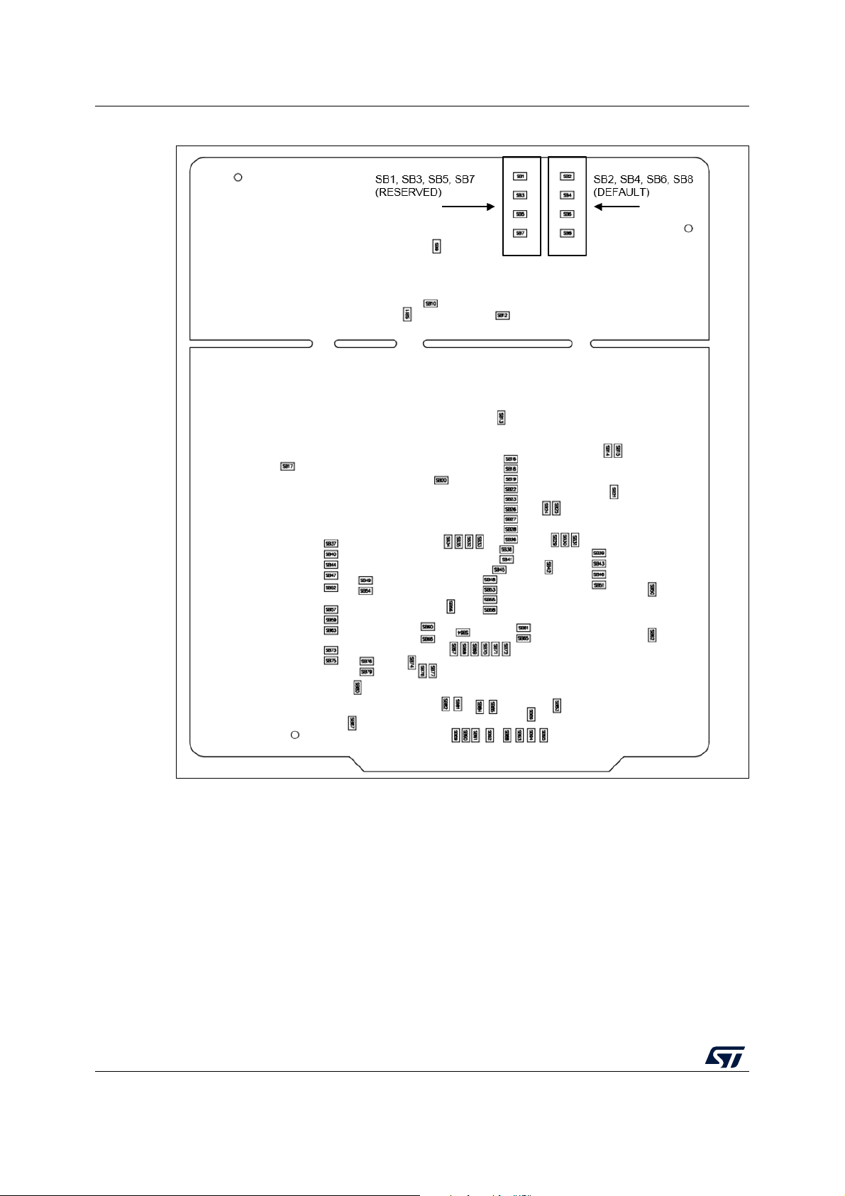
Hardware layout and configuration UM2206
Figure 5. STM32 Nucleo-64-P board bottom layout
14/50 UM2206 Rev 5
UM2206 Hardware layout and configuration
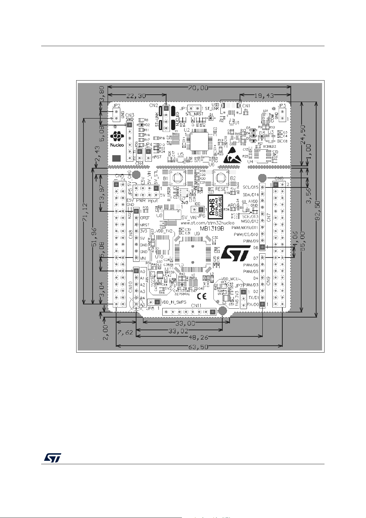
6.2 STM32 Nucleo-64-P board mechanical drawing
Figure 6. STM32 Nucleo-64 -P board mechanical drawing
6.2.1 Default board configuration
By default the STM32 Nucleo-64-P board is delivered with the external SMPS 1.1 V enabled
and V
user should check that the extension module and the external shields connected to the
Nucleo-64-P board are 1.8
The default jumper configuration and VDD@1.8 V setting is shown in Tabl e 4.
@3.3 V. It is possible to set the board for VDD@1.8 V. Before switching to 1.8 V, the
DD
V compatible.
UM2206 Rev 5 15/50
49
 Loading...