


UM2220
User manual
Getting started with MotionFX sensor fusion library in X-CUBE-MEMS1
expansion for STM32Cube
Introduction
The MotionFX is a middleware library component of the X-CUBE-MEMS1 software and runs on STM32. It provides real-time
motion-sensor data fusion. It also performs gyroscope bias and magnetometer hard iron calibration.
This library is intended to work with ST MEMS only
The algorithm is provided in static library format and is designed to be used on STM32 microcontrollers based on the ARM
Cortex® -M0+, ARM® Cortex®-M3, ARM® Cortex®-M4 or ARM® Cortex®-M7 architectures.
It is built on top of STM32Cube software technology to ease portability across different STM32 microcontrollers.
The software comes with sample implementation running on an X-NUCLEO-IKS01A2, X-NUCLEO-IKS01A3 or X-NUCLEO-
IKS02A1 expansion board on a NUCLEO-F401RE, NUCLEO-L476RG, NUCLEO-L152RE or NUCLEO-L073RZ development
board.
.
®
UM2220 - Rev 8 - April 2021
For further information contact your local STMicroelectronics sales of
fice.
www.st.com

1 Acronyms and abbreviations
Table 1. List of acronyms
Acronym Description
API Application programming interface
BSP Board support package
GUI Graphical user interface
HAL Hardware abstraction layer
IDE Integrated development environment
UM2220
Acronyms and abbreviations
UM2220 - Rev 8
page 2/25

MotionFX middleware library in X-CUBE-MEMS1 software expansion for STM32Cube
2 MotionFX middleware library in X-CUBE-MEMS1 software
expansion for STM32Cube
2.1 MotionFX overview
The MotionFX library expands the functionality of the X-CUBE-MEMS1
The library acquires data from the accelerometer, gyroscope (6-axis fusion) and magnetometer (9-axis fusion)
and provides real-time motion-sensor data fusion.
The MotionFX filtering and predictive software uses advanced algorithms to intelligently integrate outputs from
multiple MEMS sensors, regardless of environmental conditions, for an optimum performance.
The library is designed for ST MEMS only. Functionality and performance when using other MEMS sensors are
not analyzed and can be significantly different from what described in the document.
The complexity of the library dedicated to the Cortex-M0+ core is reduced due to the performance limitation of
Cortex-M0+ architecture. This library uses different APIs and has less features in comparison with the version for
Cortex-M3, Cortex-M4 and Cortex-M7 (for further details, see the following chapters).
A sample implementation is available on X-NUCLEO-IKS01A2 and X-NUCLEO-IKS01A3 expansion board,
mounted on a NUCLEO-F401RE, NUCLEO-L476RG, NUCLEO-L152RE or NUCLEO-L073RZ development
board.
software.
UM2220
2.2 MotionFX library
Technical information fully describing the functions and parameters of the MotionFX APIs can be found in the
MotionFX_Package.chm compiled HTML file located in the Documentation folder
2.2.1 MotionFX library description
The MotionFX sensor fusion library manages data acquired from accelerometer, gyroscope and magnetometer
sensor; it features:
• real-time 9-axis motion-sensor data fusion (accelerometer, gyroscope, magnetometer)
• real-time 6-axis motion-sensor data fusion (accelerometer, gyroscope)
• computation of rotation, quaternions, gravity and linear acceleration data
• gyroscope bias calibration
• magnetometer hard iron calibration
• recommended sensor data sampling frequency of 100 Hz
• resources requirements:
– Cortex-M0+: 15.9 kB of code and 2.1 kB of data memory
– Cortex-M3: 49.3 kB of code and 1.1 kB of data memory
– Cortex-M4: 44.1 kB of code and 1.1 kB of data memory
– Cortex-M7: 42.6 kB of code and 1.1 kB of data memory
• available for ARM Cortex-M0+, Cortex-M3, Cortex-M4 and Cortex-M7 architecture
2.2.2 MotionFX 6-axis and 9-axis sensor fusion modes
The MotionFX library implements a sensor fusion algorithm for the estimation of 3D orientation in space. It uses
a digital filter based on the Kalman theory to fuse data from several sensors and compensate for limitations of
single sensors. For instance, gyroscope data can drift and this impacts the orientation estimation; this issue can
be fixed by using the magnetometer to provide absolute orientation information.
Similarly
these weaknesses can be compensated with a gyroscope.
9-axis sensor fusion uses data from the accelerometer, gyroscope and magnetometer and provides absolute
orientation in 3D space including heading (i.e., the magnetic North direction).
6-axis sensor fusion uses the accelerometer and gyroscope data only. It has lower computational requirements,
but does not provide information about the device absolute orientation.
6-axis sensor fusion is fit for fast movements (e.g., for gaming) and when absolute orientation is not necessary.
, the magnetometer does not have a very high bandwidth and suffers from magnetic disturbance, but
.
UM2220 - Rev 8
page 3/25

2.2.3 MotionFX library operation
The MotionFX library integrates 6- and 9-axis sensor fusion algorithms in one library; they can even run
simultaneously to provide both rotation vector (9X) and game rotation vector (6X).
Cortex-M3, Cortex-M4 and Cortex-M7
The library implements the following critical internal functions associated with sensor fusion computation:
1.
the MotionFX_propagate is a prediction function used to estimate the orientation in 3D space; gyroscope
data is given more weight in this phase.
2. the MotionFX_update is the corrective function which adjusts the predicted value when necessary;
accelerometer and magnetometer data are given more weight in this phase.
The MotionFX_update function can be called whenever the MotionFX_propagate is invoked, or less often in
systems that have less computation power.
The MotionFX_update function takes approximately three times more MCU computation time than the
MotionFX_propagate function.
Cortex-M0+
The sensor fusion computation is concentrated in only one function MotionFX_CM0P_update.
2.2.4 MotionFX library parameters
Cortex-M3, Cortex-M4 and Cortex-M7
The library is "parametrized" using an MFX_knobs_t
The parameters for the structure are:
• ATime, MTime, FrTime represent the weighting stability of sensors for prediction (trust factor), from 0 to 1.
Default values are recommended.
– ATime: lowering the value will increase the accelerometer weight and sensitivity towards external
acceleration. If the application experiences low acceleration (<1g) most of time, it is recommended to
increase the value.
– MTime, FrTime: for 9X solution, the lower value will increase the weight of magnetometer reading.
If the application experiences low magnetic interference (<50 μT) most of time, it is recommended to
increase the value.
• LMode represents the gyroscope bias learning mode; the library automatically tracks and calibrates gyro
zero-rate bias drift.
This possible parameter values are:
– LMode = 0 – learning off; use this mode if the gyro is already calibrated
– LMode = 1 – static learning; learning is performed only when the system is not moving
– LMode = 2 – dynamic learning; learning is also performed when the system is moving
• gbias_acc/gyro/mag_th_sc represents the thresholds below which the gbias algorithm automatically
starts. These values should be established through testing (they are different for different part numbers).
The values in the example project are usually correct. The value can be determined by enabling
start_automatic_gbias_calculation, placing the device stationary for 10 seconds and reading the
value of knobs.
– modx represents the decimation of MotionFX_update call frequency
– output_type represents the sensor fusion library output orientation: 0 = NED, 1 = ENU
– start_automatic_gbias_calculation: this flag allows computing gbias_acc/gyr/
mag_sens_th_sc for an application, by placing the device stationary for 10 seconds and setting this
flag to 1 by calling MotionFX_setKnobs API. After 10 seconds or more, call MotionFX_getKnobs
API to get the value of these thresholds.
– acc/gyro/mag_orientation is the acc/gyro/mag data orientation string of three characters
indicating the direction of each positive orientation of the reference frame used for the accelerometer
data output, in the sequence x, y, z. Valid values are: n (north) or s (south), w (west) or e (east), u (up)
or d (down).
As shown in the figure below, the X-NUCLEO-IKS01A2 accelerometer sensor has an NWU orientation
(x - East, y - North, z - Up), so the string is: “nwu”.
UM2220
MotionFX library
structure.
UM2220 - Rev 8
page 4/25
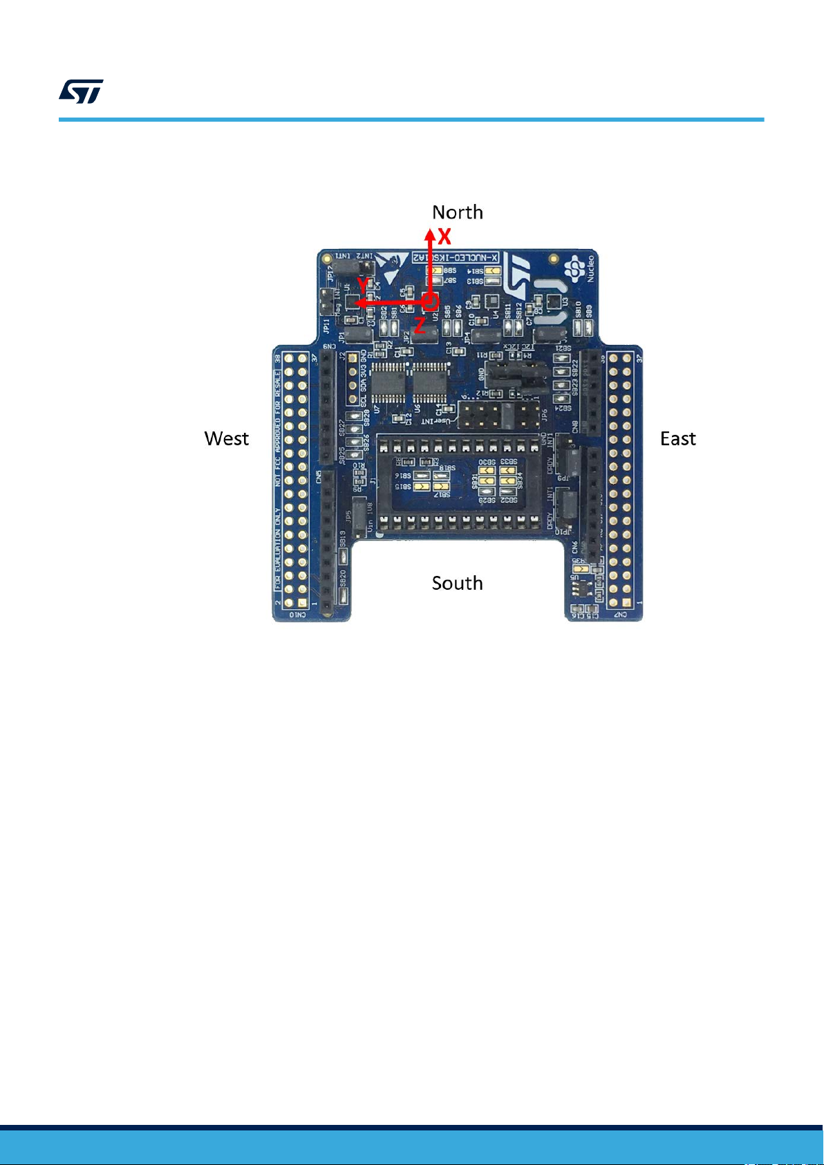
Figure 1. Example of sensor orientations
UM2220
MotionFX library
Cortex-M0+
Only the sensor orientation must be set using MotionFX_CM0P_setOrientation function. The parameters of
this function are orientation strings which are composed in the same manner as for Cortex-M3, Cortex-M4 and
Cortex-M7 (see above).
The MotionFX_propagate and the MotionFX_update (MotionFX_CM0P_update) functions receive input
from sensors in the MFX_input _t (MFX_CM0P_input_t) structure:
• mag represents magnetometer data after calibration in μT/50
• acc represents accelerometer data in g
• gyro represents gyroscope data in dps
The MotionFX_propagate and the MotionFX_update (MotionFX_CM0P_update) functions provide the
sensor fusion output in the MFX_output_t (MFX_CM0P_output_t) structure:
• rotation represents the system orientation in three-angle format: yaw, pitch and roll
MotionFX library uses the following convention yaw range: 0-360 degrees, pitch range ±180 degrees and roll
range ±90 degrees
• quaternion represents the system orientation in four-number format; this format gives the same
information as rotation but it has advantages for computation and is therefore usually used by other
algorithms (based on the sensor fusion)
• gravity represents the static acceleration (i.e., Earth gravity) vector extracted from the acceleration data
• linear_acceleration represents the dynamic acceleration (i.e., movement) vector extracted from the
acceleration data
UM2220 - Rev 8
page 5/25

• heading represents the heading of the device in degrees. Heading 0 degree represents the magnetic North
direction for 9-axis sensor fusion, while, for 6-axis sensor fusion, it represents heading of device at the
algorithm start.
• headingErr represents the heading error of the device in degrees
2.2.5 MotionFX library output data rate
It is important to set up the sensor fusion library output data rate properly; 100 Hz is recommended.
The output data rate for:
•
the gyroscope and the accelerometer should be equal to or greater than 100 Hz;
• the magnetometer can be lower - 20/40 Hz is typically good for a magnetic field sensor.
Cortex-M3, Cortex-M4 and Cortex-M7
It is possible to scale the library system requirements in terms of MCU/MPU load. As the MotionFX_update
function requires approximately three times more computation power than the MotionFX_propagate function,
it can be called at a lower frequency than the library output data rate if the system resources are limited (e.g., in
embedded systems).
Use the modx parameter in MFX_knobs_t structure to decrease the frequency of MotionFX_update
function calls. For example, setting modx to 2 calls the MotionFX_update function once every two
MotionFX_propagate function calls.
The recommended settings are:
• modx = 1, for tablets or other systems with MCU/MPU and for STM32F4;
• modx = 2, for STM32F1.
UM2220
MotionFX library
2.2.6 Sensor calibration in the MotionFX library
Gyroscope and accelerometer calibration
Accelerometer calibration is not necessary for sensor fusion except for applications demanding very high
orientation precision; it involves aligning the system in several positions according to the gravity direction.
Gyroscope calibration is handled automatically by the MotionFX library by continuously compensating the zerorate of
fset effect.
Magnetometer calibration
The MotionFX library contains routines for magnetometer hard iron calibration.
The magnetometer is affected by the hard-iron and soft-iron phenomena described below.
Hard-iron distortion
Hard-iron distortion is normally generated by ferromagnetic material with permanent magnetic fields that are part
of the object (e.g., a tablet) in use. These materials can be permanent magnets or magnetized iron or steel. They
are time invariant and deform the local geomagnetic field with different offsets in different directions.
As each board can be magnetized differently, the hard iron effect is specific to the individual board.
If you move the board around a space approximating (as much as possible) a 3D sphere in an ideal environment
(no hard-iron/soft-iron distortion) and plot the collected magnetic sensor raw data, the result is a perfect sphere
with no offset.
The hard-iron distortion effect offsets the sphere along the x, y and z axes; in the x-y plane, the hard-iron
distortion is identified by an offset of the origin of the ideal circle from (0, 0), scatter plots for XY and XZ axes are
sufficient to determine if there is an offset.
UM2220 - Rev 8
Soft-iron distortion
Soft-iron distortion is generated by magnetically soft materials or current carrying PCB traces. While hard-iron
distortion is constant regardless of the orientation, the soft-iron distortion changes with the orientation of the
object in the Earth’s field (soft magnetic materials change their magnetization direction).
The local geomagnetic field is deformed with different gain on different directions. The effect of the soft-iron to
distort the ideal full round sphere into a tilted ellipsoid; in the x-y plane, the soft-iron distortion is identified by a
tilted ellipse with the origin at (0,0) for the XY axis (XZ).
page 6/25
UM2220
MotionFX library
The soft iron effect is the same across all boards of the same design, which is why a good PCB design which
takes magnetometer placement (high current traces/other component clearance) into account can generally avoid
any soft iron effects (valid for X-NUCLEO-IKS01A2 expansion board).
Calibration procedure
The MotionFX library magnetometer calibration library compensates for hard-iron distortions.
The magnetometer calibration can be performed at a slower frequency than the sensor fusion output data rate
(e.g., 25 Hz).
To run the calibration:
1. initialize magnetometer calibration library (MotionFX_MagCal_init or MotionFX_CM0P_MagCal_init)
2. call periodically calibration function (MotionFX_MagCal_run or MotionFX_CM0P_MagCal_run) until the
calibration is successfully performed
3. check if calibration was successful (MotionFX_MagCal_getParams or
MotionFX_CM0P_MagCal_getParams); if the function returns mag_data_out.cal_quality =
MFX_MAGCALGOOD or MFX_CM0P_CALQSTATUSBEST, the calibration was successfully performed
4. apply calibration results:
– − MAG_Calibrated.AXIS_X = MAG_Value.AXIS_X - MAG_Offset.AXIS_X
– − MAG_Calibrated.AXIS_Y = MAG_Value.AXIS_Y - MAG_Offset.AXIS_Y
– − MAG_Calibrated.AXIS_Z = MAG_Value.AXIS_Z - MAG_Offset.AXIS_Z
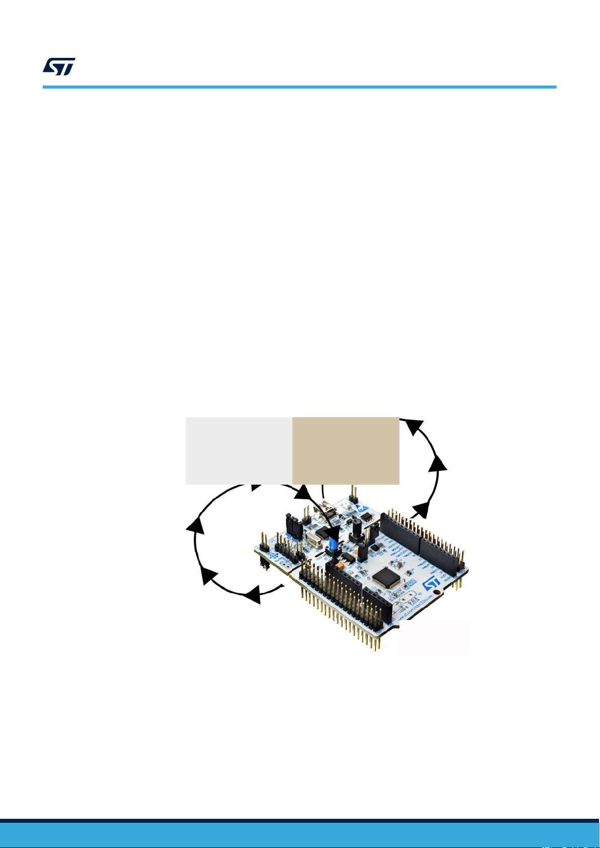
After calibration routine initialization, slowly rotate the device in a figure 8 pattern in space. While performing
this movement, keep the device clear of other magnetic objects such as cell phones, computers and other steel
objects.
Figure 2. STM32 Nucleo board rotation during calibration
To check that the calibration was performed correctly, check magnetometer data (after applying calibration results)
using the scatter plot.
UM2220 - Rev 8
page 7/25

MotionFX library
2.2.7 MotionFX APIs
The MotionFX APIs are:
Cortex-M3, Cortex-M4 and Cortex-M7
• size_t MotionFX_GetStateSize(void)
retrieves the size of the library to be allocated prior to run
–
– every instance of motionFX requires the allocation of this size
• void MotionFX_initialize(MFXState_t mfxstate_pt)
– performs MotionFX library initialization and setup of the internal mechanism
– mfxstate_pt is the pointer to the allocated memory for the instance of MotionFX
Note: This function must be called before using the sensor fusion library and the CRC module in the STM32
microcontroller (in RCC peripheral clock enable register) has to be enabled.
• uint8_t MotionFX_GetLibVersion(char *version)
– retrieves the version of the library
– *version is a pointer to an array of 35 characters
– returns the number of characters in the version string
• void MotionFX_setKnobs(MFXState_t mfxstate_pt, MFX_knobs_t *knobs)
– sets the internal knobs
– mfxstate_pt is a pointer to the allocated memory for the instance of MotionFX
UM2220
• void MotionFX_getKnobs(MFXState_t mfxstate_pt, MFX_knobs_t *knobs)
– gets the current internal knobs
– mfxstate_pt is a pointer to the allocated memory for the instance of MotionFX
– *knobs parameter is a pointer to a structure with knobs
• MFX_engine_state_t MotionFX_getStatus_6X(MFXState_t mfxstate_pt)
– gets the 6 axes library status
– mfxstate_pt is a pointer to the allocated memory for the instance of MotionFX
– returns 1 if enabled, 0 if disabled
• MFX_engine_state_t MotionFX_getStatus_9X(MFXState_t mfxstate_pt)
– gets the 9 axes library status
– mfxstate_pt is a pointer to the allocated memory for the instance of MotionFX
– returns 1 if enabled, 0 if disabled
• void MotionFX_enable_6X(MFXState_t mfxstate_pt, MFX_engine_state_t enable)
– enables or disables the 6 axes function (ACC + GYRO)
– mfxstate_pt is a pointer to the allocated memory for the instance of MotionFX
– enable parameter is 1 to enable, 0 to disable
• void MotionFX_enable_9X(MFXState_t mfxstate_pt, MFX_engine_state_t enable)
– enables or disables the 9 axes function (ACC + GYRO + MAG)
– mfxstate_pt is a pointer to the allocated memory for the instance of MotionFX
– enable parameter is 1 to enable, 0 to disable
UM2220 - Rev 8
page 8/25

UM2220
MotionFX library
• void MotionFX_setGbias(MFXState_t mfxstate_pt, float *gbias)
sets the initial gbias
–
– mfxstate_pt is a pointer to the allocated memory for the instance of MotionFX
– *gbias parameter is a pointer to a float array containing the gyro bias value for each axis
• void MotionFX_getGbias(MFXState_t mfxstate_pt, float *gbias)
– gets the initial gbias
– mfxstate_pt is a pointer to the allocated memory for the instance of MotionFX
– *gbias parameter is a pointer to a float array containing the gyro bias value for each axis
• void MotionFX_update(MFXState_t mfxstate_pt, MFX_output_t *data_out, MFX_input_t
*data_in, float *eml_deltatime, float *eml_q_update)
– runs the Kalman filter update
– mfxstate_pt is a pointer to the allocated memory for the instance of MotionFX
– *data_out parameter is a pointer to output data structure
– *data_in parameter is a pointer to input data structure
– *eml_deltatime parameter is a pointer to delta time between two propagate calls [sec]
– *eml_q_update parameter is a pointer set to NULL
• void MotionFX_propagate(MFXState_t mfxstate_pt, MFX_output_t *data_out,
MFX_input_t *data_in, float *eml_deltatime
– runs the Kalman filter propagate
– mfxstate_pt is a pointer to the allocated memory for the instance of MotionFX
– *data_out parameter is a pointer to output data structure
– *data_in parameter is a pointer to input data structure
– *eml_deltatime parameter is a pointer to delta time between two propagate calls [sec]
• void MotionFX_MagCal_init(int sampletime, unsigned short int enable)
– initializes the magnetometer calibration library
– sampletime parameter is a period in milliseconds [ms] between the update function calls
– enable parameter is to enable (1) or disable (0) library
• void MotionFX_MagCal_run(MFX_MagCal_input_t *data_in)
– runs the magnetometer calibration algorithm
– *data_in parameter is a pointer to input data structure
– the parameters for the structure type MFX_MagCal_input_t are:
◦ mag is uncalibrated magnetometer data [µT]/50
◦ time_stamp is the timestamp [ms]
• void MotionFX_MagCal_getParams(MFX_MagCal_output_t *data_out)
– gets magnetometer calibration parameters
– *data_out parameter is a pointer to output data structure
– the parameters for the structure type MFX_MagCal_output_t are:
◦ hi_bias is the hard iron offset array [µT]/50
◦ cal_quality is the calibration quality factor:
• MFX_MAGCALUNKNOWN = 0; accuracy of the calibration parameters is unknown
• MFX_MAGCALPOOR = 1; accuracy of the calibration parameters is poor, cannot be trusted
• MFX_MAGCALOK = 2; accuracy of the calibration parameters is OK
• MFX_MAGCALGOOD = 3; accuracy of the calibration parameters is good
UM2220 - Rev 8
page 9/25

UM2220
MotionFX library
Storing and loading magnetometer calibration parameters
The following functions have to be implemented specifically for each target platform:
• char MotionFX_LoadMagCalFromNVM(unsigned short int dataSize, unsigned int *data)
–
the function is used to retrieve the calibration parameters from storage, the function is called when
magnetometer calibration library is enabled
– dataSize is the size of the data in bytes
– *data is the data location pointer
– returns 0 for correct loading, 1 otherwise
• char MotionFX_SaveMagCalInNVM(unsigned short int dataSize, unsigned int *data)
– the function is used to store the calibration parameters and is called when the magnetometer
calibration library is disabled
– dataSize is the size of the data in bytes
– *data is the data location pointer
– returns 0 for correct saving, 1 otherwise
Cortex-M0+
• uint8_t MotionFX_CM0P_GetLibVersion(char *version)
– retrieves the version of the library
– *version is a pointer to an array of 35 characters
– returns the number of characters in the version string
• void MotionFX_CM0P_Initialize(MFX_CM0P_mcu_type_t mcu_type)
– performs MotionFX library initialization and setup of the internal mechanism
– mcu_type is the type of MCU:
◦ MFX_CM0P_MCU_STM32 is a standard STM32 MCU
◦ MFX_CM0P_MCU_BLUE_NRG1 is BlueNRG-1
◦ MFX_CM0P_MCU_BLUE_NRG2 is BlueNRG-2
◦ MFX_CM0P_MCU_BLUE_NRG_LP is BlueNRG -LP
Note: This function must be called before using the sensor fusion library and the CRC module in the STM32
microcontroller (in RCC peripheral clock enable register) has to be enabled.
• void MotionFX_CM0P_setOrientation(const char acc_orientation[4], const char
gyro_orientation[4], const char mag_orientation[4])
– sets sensors orientation
– acc_orienation/gyro_orientation/mag_orientation orientation strings
• MFX_CM0P_engine_state_t MotionFX_CM0P_getStatus_6X(void)
– gets the 6 axes library status
– returns 1 if enabled, 0 if disabled
• MFX_CM0P_engine_state_t MotionFX_CM0P_getStatus_9X(void)
– gets the 9 axes library status
– returns 1 if enabled, 0 if disabled
UM2220 - Rev 8
• MFX_CM0P_engine_state_t MotionFX_CM0P_getStatus_euler(void)
– gets the status of euler angles calculation
– returns 1 if enabled, 0 if disabled
page 10/25

• MFX_CM0P_engine_state_t MotionFX_CM0P_getStatus_gbias(void)
gets the status of gyroscope calibration
–
– returns 1 if enabled, 0 if disabled
• void MotionFX_CM0P_enable_6X(MFX_CM0P_engine_state_t enable)
– enables or disables the 6 axes function (ACC + GYRO)
– enable parameter is 1 to enable, 0 to disable
• void MotionFX_CM0P_enable_9X(MFX_CM0P_engine_state_t enable)
– enables or disables the 9 axes function (ACC + GYRO+MAG)
– enable parameter is 1 to enable, 0 to disable
• void MotionFX_CM0P_enable_euler(MFX_CM0P_engine_state_t enable)
– enables or disables the euler angles calculation
– enable parameter is 1 to enable, 0 to disable
• void MotionFX_CM0P_enable_gbias(MFX_CM0P_engine_state_t enable)
– enables or disables the gyroscope calibration
– enable parameter is 1 to enable, 0 to disable
• void MotionFX_CM0P_setGbias(float *gbias)
– sets the initial gbias
– *gbias parameter is a pointer to a float array containing the gyro bias value for each axis
UM2220
MotionFX library
• void MotionFX_CM0P_getGbias(float *gbias)
– gets the initial gbias
– *gbias parameter is a pointer to a float array containing the gyro bias value for each axis
• void MotionFX_CM0P_update(MFX_CM0P_output_t *data_out, MFX_CM0P_input_t
*data_in, float deltatime)
– runs the sensor fusion algorithm
– *data_out parameter is a pointer to output data structure
– *data_in parameter is a pointer to input data structure
– deltatime parameter is a delta time between two propagate calls [sec]
• void MotionFX_CM0P_MagCal_init(int sampletime, unsigned short int enable)
– initializes the magnetometer calibration library
– sampletime parameter is a period in milliseconds [ms] between the update function calls
– enable parameter is to enable (1) or disable (0) library
• void MotionFX_CM0P_MagCal_run(MFX_MagCal_CM0P_input_t *data_in)
– runs the magnetometer calibration algorithm
– *data_in parameter is a pointer to input data structure
– the parameters for the structure type MFX_MagCal_CM0P_input_t are:
◦ mag is uncalibrated magnetometer data [µT/50]
UM2220 - Rev 8
page 11/25

MotionFX library
• void MotionFX_CM0P_MagCal_getParams(MFX_CM0P_MagCal_output_t *data_out)
gets magnetometer calibration parameters
–
– *data_out parameter is a pointer to output data structure
– the parameters for the structure type MFX__CM0P_MagCal_output_t are:
◦ hi_bias is the hard iron offset array [µT/50]
◦ cal_quality is the calibration quality factor:
• MFX_CM0P_MAGCALUNKNOWN = 0; accuracy of the calibration parameters is unknown
• MFX_CM0P_MAGCALPOOR = 1; accuracy of the calibration parameters is poor, cannot be
trusted
• MFX_CM0P_MAGCALOK = 2; accuracy of the calibration parameters is OK
• MFX_CM0P_MAGCALGOOD = 3; accuracy of the calibration parameters is good
UM2220
UM2220 - Rev 8
page 12/25

2.2.8 API flow chart
Wait Expiring Timer
Update
Read Acc+Gyr+Mag Data
GetLibVersion
Start
Get MotionFX Outputs
Data Read Interrupt
Initialize
MagCal_Init
getKnobs/setKnobs
Propagate
MagCal_run / MagCal_getParams
UM2220
MotionFX library
Figure 3. MotionFX API logic sequence
2.2.9 Demo code
The following demonstration code reads data from the accelerometer, gyroscope and magnetometer sensors and
gets the rotation, quaternions, gravity and linear acceleration.
UM2220 - Rev 8
page 13/25

#define MFX_STR_LENG 35
#define STATE_SIZE (size_t)(2450)
#define ENABLE_6X 0
[...]
/*** Initialization ***/
char lib_version[MFX_STR_LENG];
static uint8_t mfxstate[STATE_SIZE];
MFX_knobs_t iKnobs;
float LastTime;
/* Check if statically allocated memory size is sufficient
to store MotionFX algorithm state and resize if necessary */
if (STATE_SIZE < MotionFX_GetStateSize())
Error_Handler();
/* Sensor Fusion API initialization function */
MotionFX_initialize((MFXState_t *)mfxstate);
/* Optional: Get version */
MotionFX_GetLibVersion(lib_version);
UM2220
MotionFX library
/* Modify knobs settings & set the knobs */
MotionFX_getKnobs(mfxstate, &iKnobs);
[...]
MotionFX_setKnobs(mfxstate, &iKnobs);
MotionFX_enable_6X(mfxstate, MFX_ENGINE_DISABLE);
MotionFX_enable_9X(mfxstate, MFX_ENGINE_DISABLE);
/* Enable 9-axis sensor fusion */
if (ENABLE_6X == 1)
{
MotionFX_enable_6X(mfxstate, MFX_ENGINE_ENABLE);
}
else
{
MotionFX_enable_9X(mfxstate, MFX_ENGINE_ENABLE);
}
[...]
/*** Using Sensor Fusion algorithm ***/
Timer_OR_DataRate_Interrupt_Handler()
{
MFX_input_t data_in;
MFX_output_t data_out;
float dT;
float *q; /* Quaternion pointer to either to Game Rotation or Rotation vector (4 length) */
UM2220 - Rev 8
/* Get acceleration X/Y/Z in g */
MEMS_Read_AccValue(data_in.acc[0], data_in.acc[1], data_in.acc[2]);
/* Get angular rate X/Y/Z in dps */
MEMS_Read_GyroValue(data_in.gyro[0], data_in.gyro[1], data_in.gyro[2]);
/* Get magnetic field X/Y/Z in uT/50 */
MEMS_Read_MagValue(data_in.mag[0], data_in.mag[1], &data_in.mag[2]);
page 14/25

/* Calculate elapsed time from last accesing this function in seconds */
dT = CurrentTime - LastTime;
LastTime = CurrentTime;
/* Run Sensor Fusion algorithm */
MotionFX_propagate(mfxstate, data_out, data_in, &delta_time);
MotionFX_update(mfxstate, data_out, data_in, &delta_time, NULL);
if (ENABLE_6X == 1)
{
q = data_out.quaternion; /* Game rotation Vector */
}
else
{
q = data_out.quaternion; /* Rotation Vector in 9X */
}
}
UM2220
Sample application
2.2.10 Algorithm performance
Table 2. Cortex-M4 and Cortex-M3: elapsed time (µs) algorithm
Cortex-M4 STM32F401RE at 84 MHz Cortex-M3 STM32L152RE at 32 MHz
STM32CubeIDE
1.2.0
Min Avg Max Min Avg Max Min Avg Max Min Avg Max Min Avg Max Min Avg Max
<1 1885 1943 <1 1235 1926 <1 2011 2059 1 6823 24213 3 3893 24109 1 4707 14213
IAR EWARM
8.32.3
Table 3. Cortex-M0+ and Cortex-M7: elapsed time (µs) algorithm
Cortex-M0+ STM32L073RZ at 32 MHz Cortex-M7 STM32F767ZI at 96 MHz
STM32CubeIDE
1.2.0
Min Avg Max Min Avg Max Min Avg Max Min Avg Max Min Avg Max Min Avg Max
3 4573 5036 3 1851 4776 3 2042 2117 1 2995 3038 1 1809 1841 1 2840 2881
IAR EWARM
8.32.3
2.3 Sample application
The MotionFX middleware can be easily manipulated to build user applications. A sample application is provided
in the Application folder
It is designed to run on a NUCLEO-F401RE, NUCLEO-L476RG, NUCLEO-L152RE or NUCLEO-L073RZ
development board connected to an X-NUCLEO-IKS01A2, X-NUCLEO-IKS01A3 or X-NUCLEO-IKS02A1
expansion board.
The application provides real-time motion-sensor data fusion and returns rotation, quaternions, gravity, linear
acceleration, heading and heading error.
.
Keil µVision 5.27
Keil µVision 5.27
STM32CubeIDE
1.2.0
STM32CubeIDE
1.2.0
IAR EWARM 8.32.3 Keil µVision 5.27
IAR EWARM 8.32.3 Keil µVision 5.27
UM2220 - Rev 8
page 15/25

Figure 4. STM32 Nucleo: LEDs, button, jumper
UM2220
Sample application
The above figure shows the user button B1 and the three LEDs of the NUCLEO-F401RE board. Once the board
is powered, LED LD3 (PWR) turns ON.
Note:
After powering the board, LED LD2 blinks once indicating the application is ready.
Initially, the magnetometer calibration data are loaded from the MCU internal flash memory and checked for data
validation and good calibration quality.
If the data are valid and the calibration quality is good the LED2 is switched ON, if not the magnetometer needs
calibration and LED2 is turned OFF; in this case the calibration routine is initialized (only for NUCLEO-F401RE,
NUCLEO-L476RG, NUCLEO-L152RE).
To calibrate the magnetometer, perform the figure 8 calibration movement.
Note: You can calibrate the magnetometer only when the sensor fusion is activated.
When user button B1 is pressed, the system clears old magnetometer calibration data and starts the calibration
routine again.
To calibrate the magnetometer, perform the figure 8 calibration movement.
As soon as the magnetometer calibration finishes, after acquiring enough data, LED2 turns ON indicating that the
calibration quality is good.
Note: You can calibrate the magnetometer only when the sensor fusion is activated.
2.3.1 Unicleo-GUI application
The sample application uses the Windows Unicleo-GUI utility
Step 1. Ensure that the necessary drivers are installed and the STM32 Nucleo board with appropriate
expansion board is connected to the PC.
, which can be downloaded from www.st.com.
UM2220 - Rev 8
page 16/25
Step 2. Launch the Unicleo-GUI application to open the main application window.
If an STM32 Nucleo board with supported firmware is connected to the PC, it is automatically detected
and the appropriate COM port is opened.
Figure 5. Unicleo main window
UM2220
Sample application
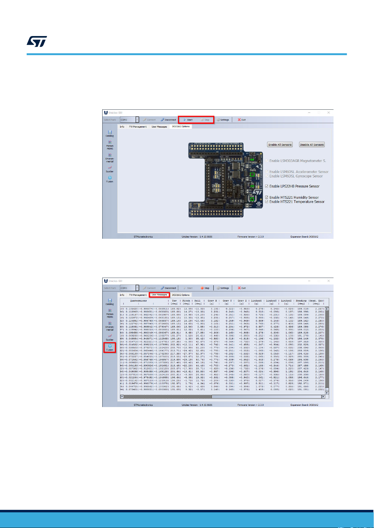
Step 3. Start and stop data streaming by using the appropriate buttons on the vertical tool bar.
The data coming from the connected sensor can be viewed in the User Messages tab.
Figure 6. User Messages tab
UM2220 - Rev 8
page 17/25

Sample application
Step 4. Click on the Fusion icon in the vertical toolbar to open the dedicated application window.
To switch between 9-axes and 6-axes sensor fusion click on the appropriate button.
To align the tea pot position point the Nucleo board towards the screen and press Reset model button.
Figure 7. Fusion window
UM2220
UM2220 - Rev 8
page 18/25

Step 5. Click on the Scatter Plot icon to check the magnetometer calibration quality.
Figure 8. Magnetometer scatter plot (properly calibrated magnetometer)
UM2220
Sample application
UM2220 - Rev 8
page 19/25

UM2220
References
Step 6. Click on the Datalog icon in the vertical toolbar to open the datalog configuration window: you can
select the sensor and fusion data to be saved in the files. You can start or stop saving by clicking on
the corresponding button.
Figure 9. Datalog window
2.4 References
All of the following resources are freely available on www.st.com.
1. UM1859: Getting started with the X-CUBE-MEMS1 motion MEMS and environmental sensor software
expansion for STM32Cube
2. UM1724: STM32 Nucleo-64 boards (MB1136)
3. UM2128: Getting started with Unicleo-GUI for motion MEMS and environmental sensor software expansion
for STM32Cube
UM2220 - Rev 8
page 20/25
Revision history
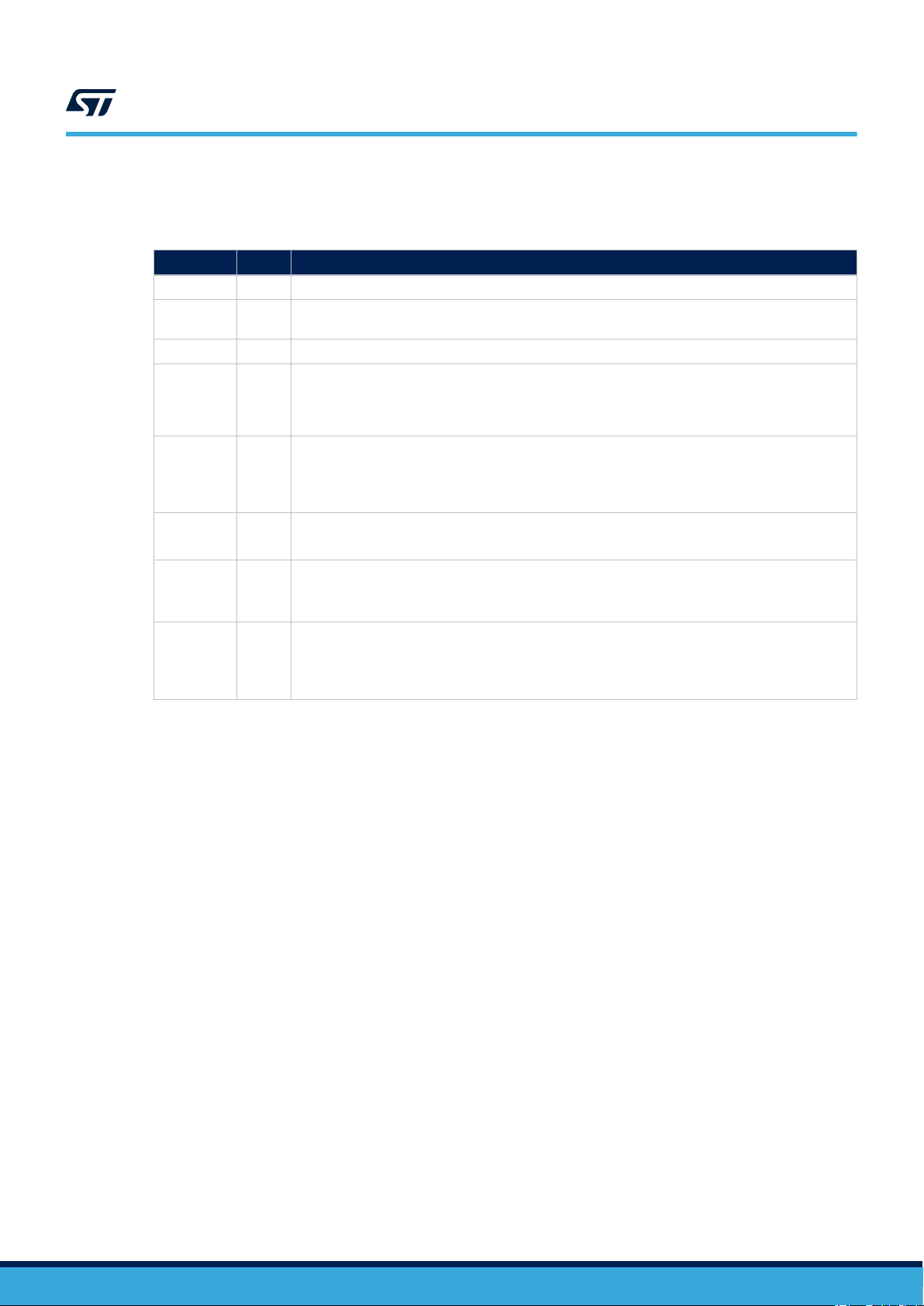
Date Version Changes
12-May-2017 1 Initial release.
26-Jan-2018 2
20-Mar-2018 3 Updated Introduction, Section 2.1: "MotionFX overview" and Section 2.2.9: "Demo code".
02-May-2018 4
01-Oct-2018 5
18-Feb-2019 6
26-Mar-2020 7
08-Apr-2021 8
UM2220
T
able 4. Document revision history
Added references to NUCLEO-L152RE development board and Section 2.2.10 Algorithm
performance.
Updated Section 2.2.7 MotionFX APIs and Figure 3. MotionFX API logic sequence.
Added T
able 3. Cortex-M0+: elapsed time (μs) algorithm.
Added references to NUCLEO-L073RZ and ARM® Cortex®-M0+.
Removed references to X-NUCLEO-IKS01A1 throughout document.
Updated Section 2.2.4 MotionFX library parameters, T
time (µs) algorithm, Figure 4. STM32 Nucleo: LEDs, button, jumper and Section 3.1 Unicleo-GUI
application.
Updated Section 2.2.10 Algorithm performance.
Added X-NUCLEO-IKS01A3 expansion board compatibility information.
Updated Introduction, Section 2.2.1 MotionFX library description, Section 2.2.3 MotionFX library
operation, Section 2.2.9 Demo code and Section 2.2.10 Algorithm performance.
Added ARM Cortex-M7 architecture compatibility information.
Updated Introduction, Section 2.2.1 MotionFX library description, Section 2.2.4 MotionFX library
parameters, Section 2.2.6 Sensor calibration in the MotionFX library, Section 2.2.7 MotionFX APIs,
Section 2.2.9 Demo code and Section 2.3 Sample application.
Added X-NUCLEO-IKS02A1 compatibility information.
able 2. Cortex-M4 and Cortex-M3: elapsed
UM2220 - Rev 8
page 21/25

UM2220
Contents
Contents
1 Acronyms and abbreviations ......................................................2
2 MotionFX middleware library in X-CUBE-MEMS1 software expansion for STM32Cube
....................................................................................3
2.1 MotionFX overview .............................................................3
2.2 MotionFX library ...............................................................3
2.2.1 MotionFX library description ................................................3
2.2.2 MotionFX 6-axis and 9-axis sensor fusion modes ................................3
2.2.3 MotionFX library operation .................................................4
2.2.4 MotionFX library parameters ................................................4
2.2.5 MotionFX library output data rate ............................................6
2.2.6 Sensor calibration in the MotionFX library ......................................6
2.2.7 MotionFX APIs ..........................................................8
2.2.8 API flow chart ..........................................................13
2.2.9 Demo code ............................................................13
2.2.10 Algorithm performance ...................................................15
2.3 Sample application ............................................................15
2.3.1 Unicleo-GUI application ..................................................16
2.4 References...................................................................20
Revision history .......................................................................21
UM2220 - Rev 8
page 22/25

UM2220
List of tables
List of tables
T
able 1. List of acronyms ....................................................................2
Table 2. Cortex-M4 and Cortex-M3: elapsed time (µs) algorithm ......................................... 15
Table 3. Cortex-M0+ and Cortex-M7: elapsed time (µs) algorithm ........................................15
Table 4. Document revision history .............................................................21
UM2220 - Rev 8
page 23/25

UM2220
List of figures
List of figures
Figure 1. Example of sensor orientations .........................................................5
Figure 2. STM32 Nucleo board rotation during calibration .............................................7
Figure 3. MotionFX API logic sequence ......................................................... 13
Figure 4. STM32 Nucleo: LEDs, button, jumper ................................................... 16
Figure 5. Unicleo main window............................................................... 17
Figure 6. User Messages tab ................................................................17
Figure 7. Fusion window ...................................................................18
Figure 8. Magnetometer scatter plot (properly calibrated magnetometer) ..................................19
Figure 9. Datalog window .................................................................. 20
UM2220 - Rev 8
page 24/25

UM2220
IMPORTANT NOTICE – PLEASE READ CAREFULLY
STMicroelectronics NV and its subsidiaries (“ST”) reserve the right to make changes, corrections, enhancements, modifications, and improvements to ST
products and/or to this document at any time without notice. Purchasers should obtain the latest relevant information on ST products before placing orders. ST
products are sold pursuant to ST’
Purchasers are solely responsible for the choice, selection, and use of ST products and ST assumes no liability for application assistance or the design of
Purchasers’ products.
No license, express or implied, to any intellectual property right is granted by ST herein.
Resale of ST products with provisions different from the information set forth herein shall void any warranty granted by ST for such product.
ST and the ST logo are trademarks of ST. For additional information about ST trademarks, please refer to www
names are the property of their respective owners.
Information in this document supersedes and replaces information previously supplied in any prior versions of this document.
s terms and conditions of sale in place at the time of order acknowledgement.
.st.com/trademarks. All other product or service
© 2021 STMicroelectronics – All rights reserved
UM2220 - Rev 8
page 25/25
 Loading...