

Page 1

AN5411
Application note
I-CUBE-LRWAN embedding FUOTA, application implementation
Introduction
This application note describes the FUOTA application embedded in the expansion software (I-CUBE-LRWAN) implementation
on STM32L4 Series devices, and explains how to make use of the overall FUOTA process in order to provide the components
needed for a FUOTA campaign.
This document applies within the framework of a FUOTA project, and is intended for teams or individuals, either internal
or external to ST. It particularly targets FUOTA project integrators, or those integrating FUOTA modules in a wider system
implementing end-device functions.
LoRa® is a type of wireless telecommunication network designed to allow long range communication at a very low bit
rate, enabling long-life battery operated sensors. LoRaWAN® defines the communication and security protocol to ensure
interoperability with LoRa networks.
AN5411 - Rev 2 - March 2021
For further information contact your local STMicroelectronics sales office.
www.st.com
Page 2
1 General information
This document applies to STM32L476xx Series Arm®-based microcontrollers.
Note: Arm is a registered trademark of Arm Limited (or its subsidiaries) in the US and/or elsewhere.
AN5411
General information
AN5411 - Rev 2
page 2/33
Page 3
AN5411
Overview
2 Overview
The FUOTA application in I-CUBE-LRWAN is compliant with the LoRa Alliance® specification protocol (LoRaWAN
version V1.0.3) [1].
The FUOTA feature is implemented in the application layer, and is based on and compliant with the specific
functionalities defined by the LoRA Alliance. These functionalities allow a multicast group (Remote Multicast
Setup Spec V1.0.0 [4]) to be set up, to fragment and to send data packets (Fragmented Data Block Transport
Specification v1.0.0 [3]) and finally to synchronize clocks (LoRaWAN Application Layer Clock Synchronization
Specification v1.0.0 [5]) so that all devices can agree on the start of a FUOTA session.
Note: Throughout this application note, the IAR™ EWARM IDE is used as an example to provide guidelines for project
configuration.
2.1 Application supports
The firmware update over-the-air (FUOTA) application supports:
• full firmware upgrade image (the entire firmware image is sent to the end-device)
• only applicable in Class-C mode
• only runs on STM32L476xx targets
• third-party middleware, mdedTLS (open source code) for the cryptographic services.
2.2
Terms and acronyms
Table 1. Acronyms used in this document
Acronym Definition
ABP Activation by personalization
APDU Application protocol data unit
FUOTA Firmware update over the air
FW Firmware
HAL Hardware abstraction layer
LoRa Long-range radio technology
LoRaWAN LoRa, wide-area network
MAC Media access control
MCPS MAC common part sublayer
MLME MAC sublayer management entity
MPDU Mac protocol data unit
MSC Message sequence chart
OTA Over-the-air
PLME Physical sublayer management Entity
PPDU Physical protocol data unit
SBSFU Secure boot and secure firmware update
SFU Secure firmware update
TPDU Transport protocol data unit
SAP Service access point
AN5411 - Rev 2
page 3/33
Page 4
Term Definition
Firmware image A binary image (executable0 run by end-device as user application
Firmware header Meta-data describing the firmware image to be installed.
mbedTLS mbedTLS implementation of the TLS and SSL protocols and the associated cryptographic algorithm.
“.sfb” file Binary file packing the firmware header and the firmware image.
2.3 References
Reference Document
[1] LoRa Alliance Specification Protocol (LoRaWAN version V1.0.3), March 2018
[2] IEEE Std 802.15.4TM - 2011. Low-Rate Wireless Personal Area Networks (LR-WPANs)
[3]
[4] LoRa Alliance Remote Multicast Setup over LoRaWAN Specification v1.0.0, September 2018 – [TS-005]
[5]
[6] AN5056 Integration Guide for the X-CUBE-SBSFU STM32Cube Expansion Package – application note
[7] UM2262 - Getting started with the X-CUBE-SBSFU STM32Cube Expansion Package – user manual
[8] UM2073 – STM32 LoRa Expansion Package for STM32 - user manual
AN5411
References
Table 2. Terms used in this document
Table 3. Document references
LoRa Alliance Fragmented Data Block Transport over LoRaWAN Specification v1.0.0, September 2018 –
[TS-004]
LoRa Alliance Application layer clock synchronization over LoRaWAN Specification v1.0.0, September 2018
– [TS-003]
AN5411 - Rev 2
page 4/33
Page 5
LoRa standard and FUOTA application feature
3 LoRa standard and FUOTA application feature
This section provides a general overview of the LoRa and LoRaWAN recommendations. It deals in particular with
the LoRa end-device and the FUOTA feature, which are the core subjects of this application note.
The LoRa software expansion is compliant with the LoRa Alliance LoRaWAN specification protocol [1].
3.1 Network architecture
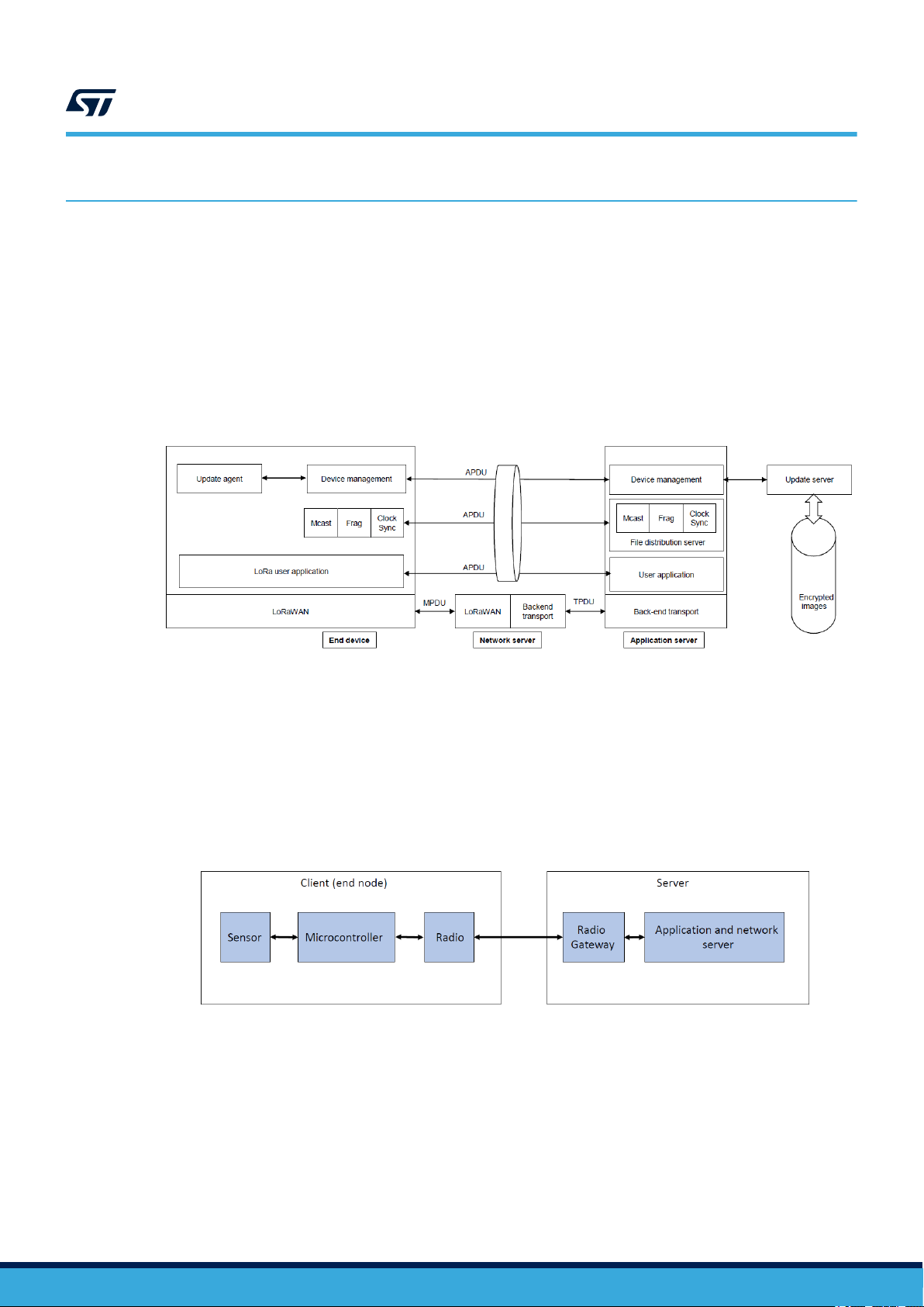
Figure 1 shows the components and their protocol relationships, allowing the implementation of the firmware-
over-the-air feature.
Figure 1. Network diagram
AN5411
Note: In the I-CUBE-LRWAN FUOTA package, the device management block is not implemented. The LoRa Alliance
technical FUOTA working group is working on a LoRaWAN Firmware Management Protocol Specification, which
documents and defines this block. The proposed implementation in the FUOTA application is a proof of concept.
3.1.1 Client/server architecture
The end-device where the software or firmware is to be updated is referred to as the end node or client. The other
part of the system is referred to as the cloud or server, and provides the new software or firmware ( Figure 2).
Figure 2. Client/server architecture example
AN5411 - Rev 2
page 5/33
Page 6
AN5411
End-device classes
3.1.2 End-device architecture
An end-device consists of a host MCU that reads sensor data in order to transmit the sensor reading over the
LoRa network by means of the LoRa radio module.
Data is encrypted by the host MCU and the radio packet is received by the gateway, which forwards it to the
network server. The network server then sends data to the application server, which has the right key to decrypt
the application data.
3.2 End-device classes
LoRaWAN [1] has several end-device classes to address the various needs of a wide range of applications.
The FUOTA application described in this application note is only 'Class-C enable'. In other words the FUOTA
application is validated for network infrastructure supporting only Class-C mode.
Note: The end-device supports Class-B mode. Nevertheless it is only 'Class B capable'. To be 'Class B enable' it is
mandatory to proceed to a new integration and validation phase on a network infrastructure supporting Class-B
mode for the FUOTA campaign.
3.2.1 Class definition
• Bi-directional end devices - Class A - (all devices) see [1]
• Bi-directional end-devices with scheduled receive slots - Class B – (Beacon) see [1]
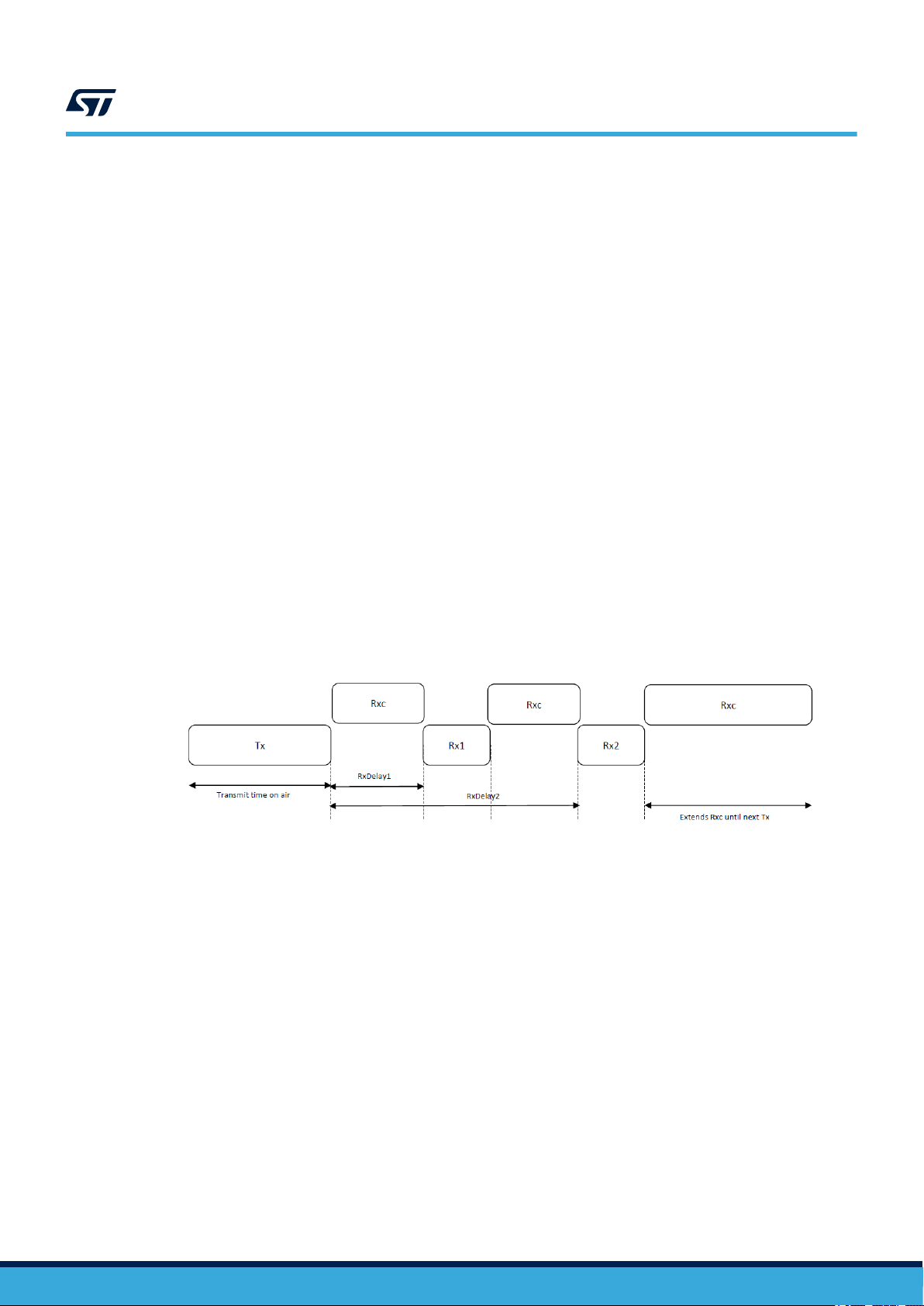
• Bi-directional end-devices with maximal receive slots - Class C – (Continuous)
Class-C mode is implemented to support FUOTA. Class-C end devices have almost continuously-open receive
windows (RxC where the data blocks are received), and are only closed when transmitting (Tx) and receiving
(Rx1, Rx2) in Class-A mode (Figure 3).
Figure 3. Tx/Rx timing diagram (Class C)
AN5411 - Rev 2
page 6/33
Page 7
3.3 FUOTA - firmware update over the air
The FUOTA update process transfers a new software image (data file) from the server to the client, and updates
the current software image (version N) running on the client with the new received software image (version N+1).
Obstacles to successful completion of the FUOTA update process are:
• Communication. The new firmware image must be sent from the server to the client. This challenge is
performed through the application-layer protocols running over LoRaWAN, which provide remote-multicast
setup, fragmented data-block transport, and application-layer clock-synchronization services. The LoRaWAN
Mac layer provides Class-C mode to transmit the data file in unicast or multicast mode.
• Firmware update. The client must migrate from the current to the new firmware image. This task is
performed by the Update_Agent module. To succed, the Update_Agent module relies on the services
provided by the SBSFU application.
• Memory. The software architecture must be organized so that it can be executed when the update process
completes. The solution must ensure the recovery of the new software version if there are installation issues.
This task is handled by the SBSFU application.
• Security. When a new firmware image is sent wirelessly from server to client, several security services
must be assured, such as: authentication, confidentiality and integrity. This must be done either through the
LoRaWAN protocol or by means of the SBSFU application security services.
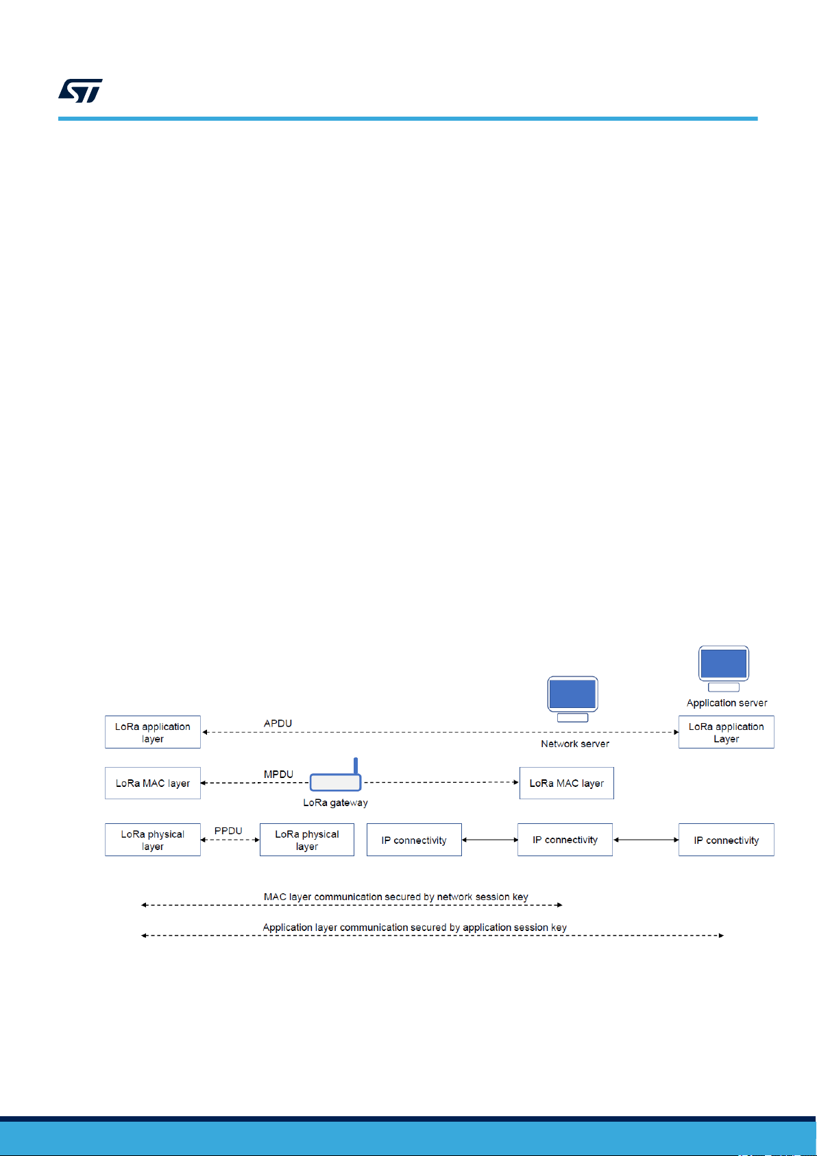
3.4 Network protocol architectures
This section describes the end-to-end network protocol architecture (see Figure 4). The following protocol
exchanges are used:
• MAC protocol data unit exchanges (MPDU)
• application protocol of an application data unit exchanges (APDU)
• LoRaWAN protocol physical protocol data unit layer (PPDU).
AN5411
FUOTA - firmware update over the air
Figure 4. LoRa network protocols
AN5411 - Rev 2
page 7/33
Page 8
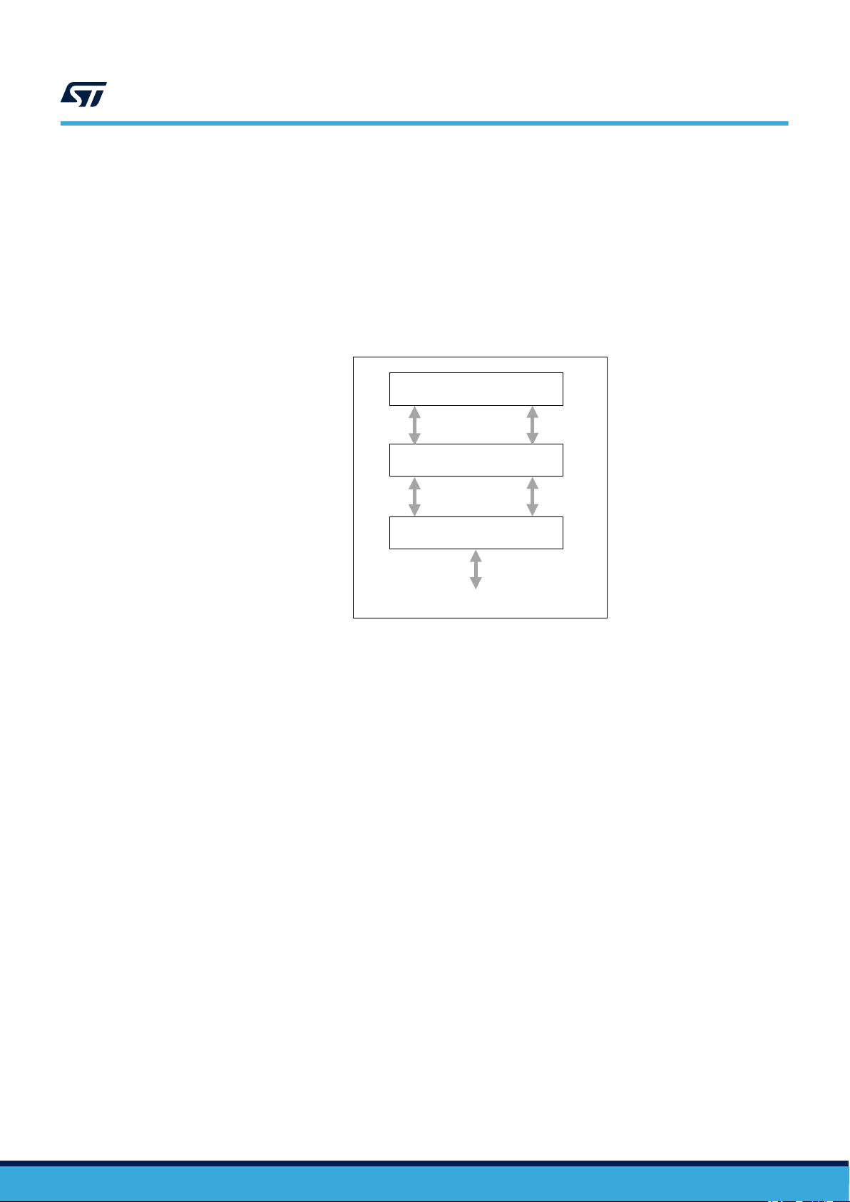
3.4.1 Network layer
The LoRaWAN architecture is defined in terms of blocks called layers. As shown in Figure 5, each layer is
responsible for one part of the standard and offers services to higher layers. An end-device is made up of :
• a PHY, which embeds the radio frequency transceiver
• the MAC sublayer that provides access to the physical channel
• application layers that provide access to the LoRaWAN services protocol.
AN5411
Network protocol architectures
Figure 5. LoRaWAN layers
Upper layers (apps)
MAC
3.4.2 Physical layer (PHY)
The physical layer provides two services:
• the PHY data service enables the Tx/Rx of physical protocol data units (PPDUs)
• the PHY management service enables the personal-area network-information base (PIB) management.
3.4.3 MAC layer
The MAC layer provides two services:
• The MAC data service enables transmission and reception of MAC protocol data units across the physical
layer (MPDU)
• The MAC sublayer management enables the PIB management.
Phy
Physical medium (air interface)
AN5411 - Rev 2
page 8/33
Page 9

3.4.4 Application layer
The application layer provides several messaging packages running over the LoRaWAN protocol. Here, FUOTA
scopes the following:
A clock synchronization package (port Number 202)
• Synchronizes the end-device real-time clock to the network’s GPS
• Makes all end devices of a multicast group to switch to Class C temporarily and synchronously.
A fragmented-data-block transport package (port Number201)
• Sets up / reports / deletes fragmentation transport sessions
• Several fragmentation sessions may be supported simultaneously by an end-device
• Fragmentation can be used either over multicast or unicast
• Reports the status of a fragmentation session.
A remote multicast setup package (port Number 200)
• Remotely creates a multicast group security context inside a group of end devices
• Reports the list of multicast contexts existing in the end-device
• Remotely deletes a multicast security context.
• Programs a Class-C multicast session
• Programs a Class-B multicast session.
Firmware management package (port Number 203) - (proof-of-concept implementation only)
• Queries/manages the firmware version running on an end-device (including availability of the firmwareupdate version)
• Queries/manages the end-device hardware version
• Manages the end-device reboot at a given time.
Update agent module
• Interfaces a LoRaWAN stack block to an SBSFU block
• Get and transmit the complete file (after recombination) to the secure firmware update (SFU) process of the
SBSFU.
User application
• Sensor/actuator processing – application use cases
• Required to start a FUOTA session, with some user uplinks to open useful Rx windows for the packages
described above.
AN5411
Network/end-device interworking
3.5
Network/end-device interworking
This section only shows the information flow between end-device and application server at the application-layer
level during a FUOTA campaign. For a complete view and description of the end-device and network interactions,
refer to the STM32 LoRa expansion package user manual [8].
3.5.1 Multicast and fragmentation set-up
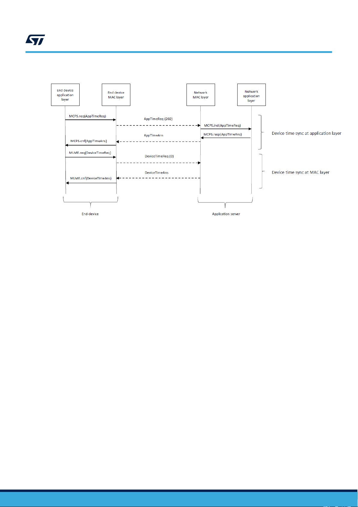
Time synchronization
Before seting up a FUOTA session, the end-device must have synchronized its timing with the network using
either AppTimeReq or DeviceTimeReq as shown in Figure 6.
AN5411 - Rev 2
page 9/33
Page 10
Network/end-device interworking
Figure 6. Message sequence chart for device timing
AN5411
Note: For the purposes of this presentation, the TimeReq sent by the MSC is divided into DeviceTimeReq and
AppTimeReq parts. The LoRaWAN specification allows a MAC command to be piggybacked in an application
payload. In the current implementation DeviceTimeReq is piggybacked in the AppTimeReq payload.
Multicast, fragmentation setup and session creation (Class C only)
In order to receive a data block at the application level, it is necessary to have some exchanges between the
network application layer and the end-device application layer. These exchanges are mainly to define: a Multicast
Group ID, the fragmentation parameters (frag number and frag size), and the multicast Class C session (start time
and end time).
AN5411 - Rev 2
page 10/33
Page 11

Network/end-device interworking
Figure 7. Message sequence chart for Class-C creation
AN5411
Fragment broadcasting and secure FW update process
As soon as the end-device is synchronized (Class C), it opens its Rx window in order to receive the data
fragments [3]. It stays in this state until all the data fragments are recieved.
When the complete data block (see the note below) is received, the end-device closes its Rx windows, and if
everything is OK from the 'data-block transfer' point-of-view, the end-device calls the UpdateAgent to start the
secure firmware update (SFU) process.
AN5411 - Rev 2
page 11/33
Page 12

Network/end-device interworking
Figure 8. Message sequence chart for data block broadcasting
AN5411
End device
App layer
Device Waiting for Class C or Class B session
Device Sync / Rx Wind ON
MCPS.Ind(Frag #1)
MCPS.Ind(Frag #2)
…………
MCPS.Ind(Frag #n- 1)
MCPS.Ind(Frag #n)
Add proprietary user protocol when the data block has been fully reconstructed
Data block transferred / Rx wind OFF
End Device
End device
MAC layer
Frag #1 (201)
Frag #2 (201)
…………
Frag #n- 1 (201)
Frag #n (201)
Network
MAC layer
Network
App layer
MCPS.Req(Frag #1)
MCPS.Req(Frag #2)
………………..
MCPS.Req(Frag #n- 1)
MCPS.Req(Frag #n)
App server
Data fragments broadcasted
When the complete Data block has been received,
Starts the update agent.
Note: Additional user 'proprietary' protocol statement:
The V1.0 package, and particularly Fragmented Data Transport TS-004, does not provide a way to inform the
server that all data blocks have been properly received in order to rebuild the current download file. This is the
case in the currently proposed implementation. The server always sends all the fragments (uncoded and coded),
even if the current download file has been rebuilt before the end of the complete broadcast fragmentation
transaction.
If needed, the user is responsible for implementing a 'proprietary' protocol to avoid such behavior.
For instance, when all the required fragments have been received and the current download file rebuilt, a
simple crc32 can be computed and sent back to the server. The server should decide to stop broadcasting the
remaining fragments.
This approach requires cooperation between the device maker and the network operator in order to define the
'proprietary' part of the protocol.
AN5411 - Rev 2
page 12/33
Page 13

4 SBSFU/end-device manager relationship
4.1 Secure boot (SB)
The secure boot loader (SB) is software that permanently resides in the microcontroller's read-only memory.
Secure boot checks the integrity and authenticity of the user application that is executed.
Secure boot executes every time a reset occurs and checks if there is a new firmware update process to
complete.
4.2 Secure firmware update (SFU)
Secure firmware update provides a secure implementation of in-field firmware updates, enabling secure download
of a new firmware image either through UART or firmware update to the end-device. Two firmware update
scenarios are possible:
• No new firmware to install: There is no firmware update process to complete, and secure boot (SB) does
some signature verifications and branches to the current active firmware - the (Slot#0) user application.
• New firmware to install: The firmware update process has to be completed. Secure boot (SB) transfers
control to secure firmware update (SFU), which contains the firmware-update related software. SFU does
the firmware update in Slot#1 and does a firmware swap processing from Slot#1 to Slot#0, and transfers
control to secure boot. Secure boot checks if there is an firmware update to complete, and branches to the
new firmware in Slot0#.
AN5411
SBSFU/end-device manager relationship
Figure 9. Boot flow with SBSFU and SBSFU memory map
AN5411 - Rev 2
page 13/33
Page 14

4.3 Security
Security is ensured either through the LoRaWAN protocol, or by means of SBSFU application security services.
During a Multicast session, all the end-devices share the same session keys. There is a potential risk when
one of the devices becomes compromised, as an attacker can initiate a multicast session with rogue firmware.
To counter this, the SBSFU can add a layer of security by using an asymmetric cryptography scheme. When
a firmware update is generated, the update is signed (TAG) with a private key by means of the PrepareImage
SBSFU tool [7]. When the end-device receives the firmware update, it verifies the signatures against the file
received and the public key held in the 'secure core' part of the end-device.
AN5411
Security
Figure 10. Signed firmware image
4.4
End-device memory
The firmware update over the air feature has a direct impact on the memory size (FLASH/RAM) of the enddevice. The amount of memory needed depends on the maximum size of the firmware image, the technology
used to manage the new firmware-update image, and also of the bootloader requirements. The current version
proposes a full firmware-update feature.
4.5 Update agent
During the first step of the FUOTA update process - the transfer of the data block (firmware image) from the
server to end-device, every time the end-device receives a fragment [3] coming from the server, it is stored in
SRAM. When the entire data block (new firmware image) is received from the server (all fragments received
and recombination done), it is transferred (written to Flash memory) by the UpdateAgent in the user workspace
(Slot#1). After this, the UpdateAgent generates an NVICReset in order to transfer the control of the MCU to the
secure boot loader.
Note: The full-caching mechanism approach allows the number of writes to Flash memory to be reduced. However,
this places a limit on the size of the new firmware image being downloaded. Both the caching method and the
firmware image size to update depend on the end-device SRAM size.
AN5411 - Rev 2
page 14/33
Page 15

5 Design overview
This package offers a FUOTA LoRa project for STM32L476 microcontrollers. The FUOTA LoRa project is split into
three sub-projects : SecoreBin, SBSFU and UserApps.
The middleware is provided in source-code format, and is compliant with the STM32Cube HAL driver.
AN5411
Design overview
Figure 11. Project file structure
5.1
5.2
LoRaWAN features
• LoRaWAN L2 V1.0.3
– Class A (baseline) / Class C (continuous) and Class B (beacon)
• Application Layer V1
– Clock synchronization, fragmentation data block, and remote multicast setup
• LoRaWAN RP V1.0.3
– Regional parameters
SBSFU features
5.2.1 Secure boot (root-of-trust services)
• Activation and checking of the necessary security mechanisms on the STM32L476 platform, to protect
critical operations and secret data from attack.
• Checking the authentication and integrity of the user application before execution.
AN5411 - Rev 2
page 15/33
Page 16

5.2.2 Secure firmware update (SFU)
• Detection of the new (encrypted) firmware version to install:
– from a local download service (via the Ymodem)
– pre-downloaded OTA via the user application (LoRaWAN)
• Firmware version management (check for unauthorized updates or unauthorized installation)
• Secure firmware update:
– firmware authentication and integrity check
– firmware decryption (if encryption is activated)
– firmware installation
• On error occurrence during the new image installation, recovery of the new firmware image (rollback to the
previous valid firmware version not supported)
• Execution of new installed firmware (once authenticated and integrity checked).
5.2.3 Cryptography
The official X-CUBE-SBSFU Expansion Package for STM32Cube [7] is delivered with two different cryptographic
middleware libraries, either X-CUBE-CRYPTOLIB, which requires an export control agreement, or mbedTLS
cryptographic services delivered as open-source code. The I-CUBE-LRWAN FUOTA application package only
provides the mbedTLS option.
To use X-CUBE-CRYPTOLIB, the user must download the official X-CUBE-SBSFU Expansion Package for
STM32Cube, and replace mbedTLS with X-CUBE-CRYPTOLIB in the project. These two libraries are equivalent
in terms of cryptographic services.
The I-CUBE-LRWAN FUOTA package is by default configured as: Asymmetric without encryption .
AN5411
SBSFU features
Features Asymmetric with AES encryption Asymmetric without encryption Symmetric (AES GCM)
Confidentiality AES CBC encryption (firmware binary) -
Integrity SHA256 (firmware header + firmware binary) -
Authentication
Cryptographic keys
in end-device
SHA256 of the firmware header is ECDSA signed
SHA256 of the firmware binary stored in the firmware header
Private AES CBS key (secret) public
ECDSA
5.2.4 SBSFU configuration
Cryptographic libraries
As specified in Section 5.2.3 Cryptography, the I-Cube-LRWAN FUOTA project project integrates the third-party
middleware mbedTLS (open-source code).
Public ECDSA key
Figure 12. Cryptographic library file location
AES CBC encryption
(firmware binary)
AES GCM tag ( firmware
header and firmware
binary)
Private AES GCM key
(secret)
AN5411 - Rev 2
Cryptographic default scheme
By default, the project is configured without cryptography. In this case there is no firmware encryption, only
authentication and integrity are ensured.
page 16/33
Page 17

AN5411
SBSFU features
Figure 13. Default cryptographic file structure
SBSFU application features
Configuration possibilities are offered through option compilation switches. By default the project supports local
loader, and all the security IPS are turned off to make debug easier.
Figure 14. File structure for SBFU application features
AN5411 - Rev 2
page 17/33
Page 18

5.3 Firmware architecture
Figure 15 summarizes the firmware design and the components involved in an end -device supporting the FUOTA
features.
AN5411
Firmware architecture
Figure 15. Top-level firmware design
Secure Boot Root of TRust
User application
Firmware management
Update
Secure firmware loader
Safe firmware programming
agent
Mcast Frag
Clock
sync
LmHandler
LoRaWAN
Note: As stated in Section 3.1 Network architecture, the firmware management block is not implemented.
AN5411 - Rev 2
page 18/33
Page 19

FUOTA middleware programming guidelines
6 FUOTA middleware programming guidelines
This section describes the LoRaMac handler APIs.
6.1 Middleware initialization
This function initializes the LoRaMac layer. It initializes the callback primitives of the MCPS and MLME services
(see [8]) and the run-time initialization of the LoRaMac layers (active region, Tx parameters, and so on).
Table 4. LmHandlerInit description
Function Description
LmHandlerErrorStatus_t LmHandlerInit
( LmHandlerCallbacks_t *callbacks);
Note: All packages (clock synchronization, remote multicast setup and fragmentation data block transport) are
mounted and activated by default within the LoRAWAN stack by means of the following constant:
#define LORAWAN_DATA_DISTRIB_MGT 1
LoRaMac handler initialization.
AN5411
This constant is set within the Projects\NUCLEOL476RG\Applications\LoRaWAN_FUOTA\LoRaWAN_End_Node\LoRaWAN\Target\lorawan_conf.h file.
6.2 LoRaMac process
This function processes the LoRaMac events and radio events.
Function Description
void LmHandlerProcess(void );
6.3 Package registering
This function registers the required packages (PACKAGE_ID_COMPLIANCE, PACKAGE_ID_CLOCK_SYNC,
PACKAGE_ID_REMOTE_MCAST_SETUP, PACKAGE_ID_FRAGMENTATION).
Function Description
LmHandlerErrorStatus_t
LmHandlerPackageRegister (uint8_t id, void
*params );
Table 5. LmHandlerProcess description
LoRaMac process – this function has to be called in the main loop. When no operation is
pending this function requests to enter Low-power mode.
Table 6. LmHandlerPackageRegister description
Perform registration of all the packages needed by the application. These
packages are dedicated for: synchronization, fragmentation, multicast setup,
and compliant test.
AN5411 - Rev 2
page 19/33
Page 20

6.4 LoRaWAN middleware configuration
This function configures the LoRaMAC layers (such as active region, access following keys commissioning
parameters).
Table 7. LmHandlerConfigure description
Function Description
LmHandlerErrorStatus_t LmHandlerConfigure (LmHandlerParams_t *handlerParams); LoRaMAC handler configuration.
6.5 Join a LoRa network
This function sends a Join request to a LoRa network in Class A.
Table 8. LmHandlerJoin description
Function Description
void LmHandlerJoin(ActivationType_t mode );
For OTAA mode, performs a JoinReq. For ABP devices, this is a pass-through
function.
AN5411
LoRaWAN middleware configuration
6.6 Check the join status
This function checks whether the device is joined to the network.
Table 9. LmHandlerJoinStatus description
Function Description
LmHandlerFlagStatus_t
LmHandlerJoinStatus( void );
Check the Join device status. LORAMAC_HANDLER_SET if joined, otherwise
LORAMAC_HANDLER_RESET.
6.7 LoRaWAN class change
This function requests the MAC layer to change the LoRaWAN class of the device.
Table 10. LmHandlerRequestClass description
Function Description
LmHandlerErrorStatus_t
LmHandlerRequestClass(DeviceClass_t
newClass );
6.8 Check the LoRaMac handler state
This function checks the state of the LoRaMac handler.
Switch Class Request. Only switching from class A to class B/C or from
class B/C to class A is allowed
AN5411 - Rev 2
Table 11. LmHandlerIsBusy description
Function Description
bool LmHandlerIsBusy(void); Indicates if the LoRaMac Handler is busy. Returns true or false.
page 20/33
Page 21

6.9 Send an uplink frame
This function requests the MAC layer to send a Class A uplink frame.
Function Description
LmHandlerErrorStatus_t
LmHandlerSend(LmHandlerAppData_t *appData,
LmHandlerMsgTypes_t isTxConfirmed,TimerTime_t
*nextTxIn, bool allowDelayedTx);
AN5411
Send an uplink frame
Table 12. LmHandlerSend description
Request a data appData to be sent with an indication of whether
the Tx is TxConfirmed or TxUnConfirmed.
AN5411 - Rev 2
page 21/33
Page 22

7 Getting started
7.1 FUOTA programing guide
This section describes how to generate a FUOTA application (referred to as a UserApp in the SBSFU literature).
The developer must follow this flow description step-by-step.
7.2 Folder structure
A top-level view of the file structure is shown in Figure 16.
AN5411
Getting started
Figure 16. Project file structure
7.2.1 How to generate a FUOTA application
The following steps must be followed to generate a FUOTA application.
1. SECoreBin
This step is needed to create the SECoreBin engine binary including all the required 'trusted' code and keys.
The binary is linked to the SBSFU code in step 2.
2. Secure boot and secure firmware update (SBSFU)
This step compiles the SBSFU source code implementing the state machine and protection configurations.
It links the code with the SECoreBin engine binary, including the 'trusted' code. It also generates a file that
includes symbols used by the user application to call the SE interface functions.
3. User Application (FUOTA)
This step generates the user application binary file (FUOTA) that is uploaded to the device by the SFU
process (UserApp.sfb).
It generates a binary file concatening the SBSFU binary, the user application (FUOTA) in clear format with
the corresponding FW header added (SBSFU_UserApp.bin).
Note: For each step (1, 2 and 3), open the respective sub-project: 2_images_SECoreBin (step 1), 2_images_SBSFU
(step 2), and end node (step 3) in the dedicated IDE folder. Then regenerate (make) the respective binary file.
Each sub-project is configured (in the project options) in order to call the 'postbuild.bat' file when needed.
See [7] for details on how to configure a complete SBSFU project.
AN5411 - Rev 2
page 22/33
Page 23

Figure 17. Application generations steps
AN5411
Folder structure
7.2.2 How to generate a data block (new firmware update)
To generate a new piece of firmware (N+1) to be downloaded over-the-air to allow the old current firmware (N) to
be updated, the I-CUBE-LRWAN package is delivered with the 'prepareimage' firmware image tool.
This tool comes from the original X-CUBE-SBSFU STM32Cube Expansion Package. For a complete and detailed
description of this tool, see [7] (Appendix E).
'Prepareimage' flow:
Even if only the full-firmware update feature is supported, the diff option of the prepareimage tool should
nevertheless be systematically applied. In the best case, code modification is located in adjacent sections, and
the diff may generate a useful UserApp_To_Download.bin file. In the worst case, the diff result is not relevant and
the UserApp_To_Download.bin file is the same as User_app.bin.
1. Generate the 'To_Download' image
python prepareimage.py diff -1 UserApp_v1.bin -2 UserApp_v2.bin
UserApp_To_Download.bin -a 16 --poffset UserApp_To_Download.offset
2. Generate the clear complete firmware tag (SHA256 of the clear FW)
python prepareimage.py sha256 UserApp_v2.bin UserApp_v2.sign
3. Generate the clear 'To_Download' firmware tag (SHA256 of the clear FW)
python prepareimage.py sha256 UserApp_To_Download.bin UserApp_Download.sign
4. Generate the .sfb fimware metadata (header) and the 'To_Download' binary
python prepareimage.py pack -k ECCKEY.txt -r 44 -p 1 -v 2 -f UserApp_v2.bin
-t UserApp_v2.sign --pfw UserApp_To_Download.bin --ptag UserApp_To_Download.sign
--poffset UserApp_To_Download.offset UserApp_To_Download.sfb
Note: X-CUBE-SBSFU firmware image tool preparation readme.txt is in
<project>Middlewares\ST\STM32_Secure_Engine\Utilities\KeysAndImages folder.
AN5411 - Rev 2
page 23/33
Page 24

Figure 18. File generation flow
AN5411
Folder structure
‘To_Download’ image
generation
Generate ‘Clear complete’ firmware tag
Generate Clear ‘To_Download’
fimware tag
Generate the “.sfb” firmware:
metadata (header) +
encrypted ‘To_Download’ binary
Ymodem download
7.2.3 How to download the data block (full firmware) to the end-device
There are two ways to download the firmware:
• a local download via UART virtual COM using Ymodem protocol
• remote download via over-the-air mechanisms proposed by the LoRaWAN protocol.
The Ymodem protocol should be used during the development phase, whereas the LoRaWAN protocol is a main
feature of the product. It is up to the user to choose the right approach.
For a complete description of Ymodem usage see [7].
LoRaWAN download
7.2.4 How to create and manage a FUOTA campaign
This section does not aim to define, or show how to create, a FUOTA campaign on an application server. These
aspects of a FUOTA campaign depend on the services provided by the network operator. Hence, here only the
salient points relating to FUOTA campaign support are outlined.
The application server must:
• support the following packages:
– the synchro package (TS-003) [5]
– the fragmentation package (TS-004) [3]
– the MulticastSetup package (TS-005) [4]
• support Class-C mode, as defined in the LoRaWAN specification V1.0.3 [1]
• be compliant with the 'interop test' proposed by the FUOTA working group of the LoRa Alliance
• have the capability to manage the data block (firmware image) to be downloaded.
'Interop test' is the minimum test proving that the end-device is able to receive a data block file from the server.
This minimum test is shown in Section 3.5 Network/end-device interworking.
7.2.5 How to debug the end-node application
The complete system consists of a secure boot and an end-node application. When the target resets, the secure
boot starts first. After some secure-boot checking the system jumps to the entry point of the end-node application.
Since the end-node application is linked to the secure boot, the end-node application (UserApp.bin) cannot be
downloaded directly with the debugger. In order to debug the end-node application, the following flow must be
respected:
1. Flash the target with the complete system (SBSFU_UserApp.bin) using the ST Link tools.
2. Once the target is Flashed, the sub-project can be attached to the running target. Debug (with breakpoints,
watch variables, and so on).
AN5411 - Rev 2
page 24/33
Page 25

AN5411
Software description
3. Modifications can now only be done on the end-node application. There are two ways to reload the target
with the new binary:
a. Reload the complete system (SBSFU_UserApp.bin) as described in (step 1), and attach to the target
(step 2)
b. Load the end-node application only (UserApp.sfb) via the YModem. When the target is running, attach
as described in Step 2.
For further details on how to debug an application running on SBSFU, see [8].
7.3
Software description
When the I-CUBE-LRWAN delivery is unzipped, the package has the following structure.
Figure 19. I-CUBE-LRWAN project structure
AN5411 - Rev 2
The I-CUBE-LRWAN package contains a FUOTA project. The FUOTA project is made up of three subprojects: SECoreBin, SBSFU and LoRaWAN_End_Node. Each sub-project has a dedicated IDE folder (IAR IDE
environment) containing the Lora.eww file to activate in order to start the IAR IDE debugger.
page 25/33
Page 26

7.3.1 Compilation switches
7.3.1.1 Crypto switches
SE_CoreBin instantiates the crypto scheme selected with SECBOOT_CRYPTO_SCHEME.
Symbols Description Default state
SECBOOT_ECCDSA_WITHOUT_ENCRYPT_SHA256
SECBOOT_ECCDSA_WITH_AES128_CBC_SHA25
SECBOOT_AES128_GCM_AES128_GCM_AES128_GCM
7.3.1.2 Security switch
SBSFU instantiates the security item selected through SECBOOT_DISABLE_SECURITY_IPS. When this symbol
is defined, all IP security protections are disabled (WRP, RDP, IWDG, DAP, and so on). See [8]
Table 13. Crypto switch descriptions
No FW encryption, only authentication and
integrity are ensured.
Authentication, integrity, and confidentiality are
ensured.
Authentication, integrity, and confidentiality are
ensured.
AN5411
Software description
Enabled
Disabled
Disabled
Symbols Description Default state
SECBOOT_DISABLE_SECURITY_IPS Disables all security IPs simultaneously when activated. Enabled.
7.3.1.3 Debug switch
In \Projects\NUCLEO-L476RG\Applications\LoRaWAN_FUOTA\LoRaWAN_End_Node\Core\Inc\sys_conf.h
• Debug mode can be enabled by setting the constant DEBUGGER_ON to 1
• Lower Power mode can be enabled by setting the constant LOW_POWER_DISABLE to 0
7.3.1.4 Sensor switches
When no sensor expansion board is plugged into the setup, the constant SENSOR_ENABLED is set to 0 in
\Projects\NUCLEO-L476RG\Applications\LoRaWAN_FUOTA\LoRaWAN_End_Node\Core\Inc\sys_conf.h
7.3.1.5 Switch options
Table 15 summarizes the main application configuration options.
Functon Switch option Definition Where
STATIC_DEVICE_EUI Static or dynamic end-device identify. se-identity.h
LoRa stack
Debug DEBUGGER ON Enable MCU debug mode in Sleep, Stop and Standby modes. sys_conf.h
Sensor SENSOR_ENABLED
Power LOW_POWER_DISABLE Disabled low power. sys_conf.h
STATIC_DEVICE_ADDRESS Static or dynamic end-device address. se-identity.h
ACTIVE_REGION
Table 14. Security switch description
Table 15. Switch options
Enable the band selection. By default it is
LORAMAC_REGION_EU868
Enable the call to the sensor board. It is up to the user to implement
the function call to the relevant sensor.
lora_app.h
sys_conf.h
AN5411 - Rev 2
page 26/33
Page 27

8 Memory footprint
8.1 End-node application
Values given in Table 16 are measured for the following IAR (EWARM Compiler 8.32) configuration
• optimization: optimized for size level 3
• debug option: off
• trace option: off
• expansion board: / SX1276MB1MAS
Table 16. End-node application memory footprint figures
Item Flash (bytes) RAM (bytes) Description
Application (user)
+LoRaWAN ClassA/C
+App Layer ClockSync
+App Layer Fragmentation
+App Layer RemoteMCast
+ LmHandler
+ FragDecoder
+ Remainder
Total
TBD
14653
806
1048
1609
2140
1484
8620
60664
76908
AN5411
Memory footprint
Memory footprint for the overall application
(App_user + LoRa ClassA + LoRa stack)
The RAM caching memory to receive the
data block is 67 Kbytes
Total:
60644 + 7981 (Lib) = 68625 bytes
8.2 SBSFU
Item Flash (bytes) RAM (bytes)
SE_Core.bin
Part of SFU
MbedTLS imposes a 4 Kbyte stack
Table 17. SBSFU memory footprint figures
22536
27405
5776
6709
Total:
22536 + 33181 = 55717 bytes
AN5411 - Rev 2
page 27/33
Page 28

Revision history
Date Revision Changes
04-Nov-2019 1 Initial version.
22-Mar-2021 2
AN5411
Table 18. Document revision history
Updated:
• Note in Section 3.1 Network architecture
• User application information in Section 3.4.4 Application layer.
• Section 4.2 Secure firmware update (SFU). Merged with old 'Section
4.2.1: Device update scenario' and updated content)
• Section 5.1 LoRaWAN features
• Table 4. LmHandlerInit description
• Table 7. LmHandlerConfigure description
• Table 8. LmHandlerJoin description
• Table 12. LmHandlerSend description
• Section 7.3.1.3 Debug switch
• Section 7.3.1.4 Sensor switches
• Table 15. Switch options
• Table 16. End-node application memory footprint figures
• Table 17. SBSFU memory footprint figures.
AN5411 - Rev 2
page 28/33
Page 29

AN5411
Contents
Contents
1 General information ...............................................................2
2 Overview ..........................................................................3
2.1 Application supports ............................................................3
2.2 Terms and acronyms ...........................................................3
2.3 References....................................................................4
3 LoRa standard and FUOTA application feature .....................................5
3.1 Network architecture............................................................5
3.1.1 Client/server architecture ..................................................5
3.1.2 End-device architecture ...................................................6
3.2 End-device classes .............................................................6
3.2.1 Class definition ..........................................................6
3.3 FUOTA - firmware update over the air .............................................7
3.4 Network protocol architectures ...................................................7
3.4.1 Network layer ...........................................................8
3.4.2 Physical layer (PHY) ......................................................8
3.4.3 MAC layer ..............................................................8
3.4.4 Application layer .........................................................9
3.5 Network/end-device interworking .................................................9
3.5.1 Multicast and fragmentation set-up ...........................................9
4 SBSFU/end-device manager relationship..........................................13
4.1 Secure boot (SB)..............................................................13
4.2 Secure firmware update (SFU) ..................................................13
4.3 Security .....................................................................14
4.4 End-device memory ...........................................................14
4.5 Update agent .................................................................14
5 Design overview ..................................................................15
5.1 LoRaWAN features ............................................................15
5.2 SBSFU features ..............................................................15
5.2.1 Secure boot (root-of-trust services) .......................................15
5.2.2 Secure firmware update (SFU) ............................................16
AN5411 - Rev 2
page 29/33
Page 30

AN5411
Contents
5.2.3 Cryptography ..........................................................16
5.2.4 SBSFU configuration.....................................................16
5.3 Firmware architecture ..........................................................18
6 FUOTA middleware programming guidelines ......................................19
6.1 Middleware initialization ........................................................19
6.2 LoRaMac process .............................................................19
6.3 Package registering ...........................................................19
6.4 LoRaWAN middleware configuration .............................................20
6.5 Join a LoRa network ...........................................................20
6.6 Check the join status ..........................................................20
6.7 LoRaWAN class change........................................................20
6.8 Check the LoRaMac handler state ...............................................20
6.9 Send an uplink frame ..........................................................21
7 Getting started ...................................................................22
7.1 FUOTA programing guide ......................................................22
7.2 Folder structure ...............................................................22
7.2.1 How to generate a FUOTA application .......................................22
7.2.2 How to generate a data block (new firmware update) ............................23
7.2.3 How to download the data block (full firmware) to the end-device ...................24
7.2.4 How to create and manage a FUOTA campaign ................................24
7.2.5 How to debug the end-node application ....................................24
7.3 Software description ...........................................................25
7.3.1 Compilation switches ....................................................26
8 Memory footprint .................................................................27
8.1 End-node application ..........................................................27
8.2 SBSFU ......................................................................27
Revision history .......................................................................28
Contents ..............................................................................29
List of tables ..........................................................................31
List of figures..........................................................................32
AN5411 - Rev 2
page 30/33
Page 31

AN5411
List of tables
List of tables
Table 1. Acronyms used in this document .........................................................3
Table 2. Terms used in this document ............................................................4
Table 3. Document references ................................................................. 4
Table 4. LmHandlerInit description .............................................................19
Table 5. LmHandlerProcess description ......................................................... 19
Table 6. LmHandlerPackageRegister description ................................................... 19
Table 7. LmHandlerConfigure description ........................................................ 20
Table 8. LmHandlerJoin description ............................................................20
Table 9. LmHandlerJoinStatus description ........................................................ 20
Table 10. LmHandlerRequestClass description ..................................................... 20
Table 11. LmHandlerIsBusy description .......................................................... 20
Table 12. LmHandlerSend description ........................................................... 21
Table 13. Crypto switch descriptions............................................................. 26
Table 14. Security switch description ............................................................ 26
Table 15. Switch options ..................................................................... 26
Table 16. End-node application memory footprint figures............................................... 27
Table 17. SBSFU memory footprint figures ........................................................ 27
Table 18. Document revision history ............................................................. 28
AN5411 - Rev 2
page 31/33
Page 32

AN5411
List of figures
List of figures
Figure 1. Network diagram...................................................................5
Figure 2. Client/server architecture example ......................................................5
Figure 3. Tx/Rx timing diagram (Class C) ........................................................6
Figure 4. LoRa network protocols .............................................................. 7
Figure 5. LoRaWAN layers ..................................................................8
Figure 6. Message sequence chart for device timing................................................ 10
Figure 7. Message sequence chart for Class-C creation ............................................. 11
Figure 8. Message sequence chart for data block broadcasting ........................................ 12
Figure 9. Boot flow with SBSFU and SBSFU memory map ........................................... 13
Figure 10. Signed firmware image ............................................................. 14
Figure 11. Project file structure ............................................................... 15
Figure 12. Cryptographic library file location ...................................................... 16
Figure 13. Default cryptographic file structure ..................................................... 17
Figure 14. File structure for SBFU application features ............................................... 17
Figure 15. Top-level firmware design............................................................18
Figure 16. Project file structure ............................................................... 22
Figure 17. Application generations steps ......................................................... 23
Figure 18. File generation flow ................................................................24
Figure 19. I-CUBE-LRWAN project structure ...................................................... 25
AN5411 - Rev 2
page 32/33
Page 33

AN5411
IMPORTANT NOTICE – PLEASE READ CAREFULLY
STMicroelectronics NV and its subsidiaries (“ST”) reserve the right to make changes, corrections, enhancements, modifications, and improvements to ST
products and/or to this document at any time without notice. Purchasers should obtain the latest relevant information on ST products before placing orders. ST
products are sold pursuant to ST’s terms and conditions of sale in place at the time of order acknowledgement.
Purchasers are solely responsible for the choice, selection, and use of ST products and ST assumes no liability for application assistance or the design of
Purchasers’ products.
No license, express or implied, to any intellectual property right is granted by ST herein.
Resale of ST products with provisions different from the information set forth herein shall void any warranty granted by ST for such product.
ST and the ST logo are trademarks of ST. For additional information about ST trademarks, please refer to www.st.com/trademarks. All other product or service
names are the property of their respective owners.
Information in this document supersedes and replaces information previously supplied in any prior versions of this document.
© 2021 STMicroelectronics – All rights reserved
AN5411 - Rev 2
page 33/33
 Loading...