

Page 1

STIHL RMI 632 P (CA)
{
Instruction Manual
Notice d’emploi
Page 2

G Instruction Manual
1 - 88
F Notice d’emploi
89 - 184
Page 3

Contents
English
1 Introduction
2 Guide to Using this Manual
2.1 Signal Words
2.2 Symbols in Text
3 Main Parts
3.1 Robotic Mower
3.2 Docking Station
3.3 Control Panel / Manual Controller
3.4 Installation Material
Original Instruction ManualPrinted on chlorine-free paper
4 Safety Symbols
4.1 Robotic Mower
4.2 Control Panel / Manual Controller
. . . . . . . . . . . . . . . . . . . . . . . . . . . . . . . . . . . . . . . . .
. . . . . . . . . . . . . . . . . . . . . . . . . .
. . . . . . . . . . . . . . . . . . . . . . . . . . . . . . . . . . . . . . . .
. . . . . . . . . . . . . . . . . . . . . . . . . . . . . . . . . . . . .
. . . . . . . . . . . . . . . . . . . . . . . . . . . . . . . . . . . . . . . . . .
. . . . . . . . . . . . . . . . . . . . . . . . . . . . . . . . . . . . . .
. . . . . . . . . . . . . . . . . . . . . . . . . . . . . . . . . . . . .
. . . . . . . . . . . . . . . . . . .
. . . . . . . . . . . . . . . . . . . . . . . . . . . . . . . . .
. . . . . . . . . . . . . . . . . . . . . . . . . . . . . . . . . . . . .
. . . . . . . . . . . . . . . . . . . . . . . . . . . . . . . . . . . . . .
. . . . . . . . . . . . . . . . . . .
5 IMPORTANT SAFETY INSTRUCTIONS
5.1 Intended Use
5.2 Operator
5.3 Personal Protective Equipment
5.4 Robotic Mower
5.5 Integrated Battery
5.6 Using the Robotic Mower
. . . . . . . . . . . . . . . . . . . . . . . . . . . . . . . . . . . . . . . .
. . . . . . . . . . . . . . . . . . . . . . . . . . . . . . . . . . . . . . . . . . . .
. . . . . . . . . . . . . . . . . . . . . .
. . . . . . . . . . . . . . . . . . . . . . . . . . . . . . . . . . . . . .
. . . . . . . . . . . . . . . . . . . . . . . . . . . . . . . . . .
. . . . . . . . . . . . . . . . . . . . . . . . . . .
6 Docking Station and Power Supply Safety
6.1 Warnings and Instructions
. . . . . . . . . . . . . . . . . . . . . . . . . .
7 Maintenance, Repair and Storage
7.1 Warnings and Instructions
Printing inks contain vegetable oils, paper can be recycled.
8 Operating Principle
9 Key Features
9.1 Key Features
. . . . . . . . . . . . . . . . . . . . . . . . . . . . . . . . . . . . . . .
. . . . . . . . . . . . . . . . . . . . . . . . . . . . . . . . . . . . . . .
10 Installing the Robotic Mower
. . . . . . . . . . . . . . . . . . . . . . . . . .
. . . . . . . . . . . . . . . . . . . . . . . . . . . . . . . . .
. . . . . . . . . . . . . . . . . . . . . . .
10.1 Preparing the Lawn and the Robotic Mower for
Operation
. . . . . . . . . . . . . . . . . . . . . . . . . . . . . . . . . . . . . . . . . .
10.2 Setting the Language, Date and Time
10.3 Installing the Docking Station
10.4 Installing the Perimeter Wire
. . . . . . . . . . . . . . . . . . . . . .
. . . . . . . . . . . . . . . . . . . . . . .
. . . . . . . . . . . . .
. . . . . . . . . .
. . . . . . . . . . . . . . . . . .
. . . . . . . . . . . . . .
10.5 Connecting the Perimeter Wire to the Docking
3
3
10.6 Linking the Robotic Mower and Docking Station
3
10.7 Checking the Installation
3
10.8 Programming the Robotic Mower: the Mowing
4
10.9 Completing the Initial Installation and First
4
5
11 Installing the Perimeter Wire
5
11.1 Planning the Layout of the Mowing Area
6
11.2 Making a Sketch of the Mowing Area
6
11.3 Measuring Wire Clearances with the STIHL Ruler
6
11.4 Routing the Perimeter Wire in Confined Areas
7
11.5 Routing Around Restricted Areas
7
11.6 Installing Linked Areas and Secondary Areas
7
11.7 Installing Corridors
8
11.8 Installing Search Loops
8
11.9 Installing Linking Sections
9
11.10 Accurate Mowing Along Edges
10
11.11 Sloping Terrain in the Mowing Area
11
11.12 Installing Reserve Wire
11.13 Using Wire Connectors
14
14
12 Docking Station
12.1 LED on the Docking Station
16
12.2 Docking Station Controls
16
12.3 Docking the Robotic Mower
17
12.4 Charging the Robotic Mower
18
13 Control Panel / Manual Controller Display
18
19
13.1 Information Area
13.2 Status Screens
19
14 Menu Functions
19
14.1 Navigating the Menus
20
14.2 Overview
24
14.3 Commands
. . . . . . . . . . . . . . . . . . . . . . . . . . . . . . . . . . . . . . . . . . . . .
Station
. . . . . . . . . . . . . . . . . . . . . . . . . . .
. . . . . . . . . . . . . . . . . . . . . . . . . . . . . . . . . . . . . . . . . . . . . . .
Plan
Mowing Operation
. . . . . . . . . . . . . . . . . . . . . . . . . . . . . . . . . .
. . . . . . . . . . . . . . . . . . . . . . .
. . . . . . . . . . . . . . . . . . . . . . . . . . . . . . . . .
. . . . . . . . . . . . . . . . . . . . . . . . . . . .
. . . . . . . . . . . . . . . . . . . . . . . . .
. . . . . . . . . . . . . . . . . . . .
. . . . . . . . . . . . . . . . . . . . . . . . . . .
. . . . . . . . . . . . . . . . . . . . . . . . . . .
. . . . . . . . . . . . . . . . . . . . . . . . . . . . . . . . . . . .
. . . . . . . . . . . . . . . . . . . . . . . .
. . . . . . . . . . . . . . . . . . . . . . . . . . .
. . . . . . . . . . . . . . . . . . . . . . . .
. . . . . . . . . . . . . . . . . . . . . . .
Information
. . . . . . . . . . . . . . . . . . . . . . . . . . . . . . . . . . . . . . . . .
. . . . . . . . . . . . . . . . . . . . . . . . . . . . . . . . . . .
. . . . . . . . . . . . . . . . . . . . . . . . . . . . . . . . . . . .
. . . . . . . . . . . . . . . . . . . . . . . . . . . . . . . . . . . .
. . . . . . . . . . . . . . . . . . . . . . . . . . . . . .
. . . . . . . . . . . . . . . . . . . . . . . . . . . . . . . . . . . . . . . . . .
. . . . . . . . . . . . . . . . . . . . . . . . . . . . . . . . . . . . . . . .
. . . .
. . . . . . . . . . .
. . . . . . . . . . . . . . .
. . .
. . . . .
. . . . . . . . . . . . . . . . . .
. . . . . .
. . . . . . . . . . . . . . .
26
30
30
31
33
33
33
34
34
36
36
37
37
39
40
40
40
40
41
42
42
42
42
43
44
44
44
45
45
47
47
{
© ANDREAS STIHL AG & Co. KG 2018
0478-131-8246-A. VA0.A18.
0000008183_001_GB
0478-131-8246-A
This instruction manual is protected by copyright. All rights reserved, especially the rights to reproduce, translate and process
with electronic systems.
1
Page 4

English
14.4 Information
14.5 Mowing Plan
14.6 Active Times
14.7 Mowing Duration
15 Settings
15.1 Settings Overview
15.2 iMow Settings
15.3 Installation
15.4 Safety
15.5 Service
15.6 Setting Starting Points
16 During Operation
16.1 Automatic Mowing
16.2 Mowing Duration
16.3 Adjusting the Cutting Height
. . . . . . . . . . . . . . . . . . . . . . . . . . . . . . . . . . . . . . . .
. . . . . . . . . . . . . . . . . . . . . . . . . . . . . . . . . . . . . . .
. . . . . . . . . . . . . . . . . . . . . . . . . . . . . . . . . . . . . . .
. . . . . . . . . . . . . . . . . . . . . . . . . . . . . . . . . . .
. . . . . . . . . . . . . . . . . . . . . . . . . . . . . . . . . . . . . . . . . . . .
. . . . . . . . . . . . . . . . . . . . . . . . . . . . . . . . . .
. . . . . . . . . . . . . . . . . . . . . . . . . . . . . . . . . . . . . .
. . . . . . . . . . . . . . . . . . . . . . . . . . . . . . . . . . . . . . . . .
. . . . . . . . . . . . . . . . . . . . . . . . . . . . . . . . . . . . . . . . . . . . .
. . . . . . . . . . . . . . . . . . . . . . . . . . . . . . . . . . . . . . . . . . . .
. . . . . . . . . . . . . . . . . . . . . . . . . . . . .
. . . . . . . . . . . . . . . . . . . . . . . . . . . . . . . . . . .
. . . . . . . . . . . . . . . . . . . . . . . . . . . . . . . . .
. . . . . . . . . . . . . . . . . . . . . . . . . . . . . . . . . . .
. . . . . . . . . . . . . . . . . . . . . . . .
16.4 Removing and Mounting the Control Panel /
Manual Controller
16.5 Manual Mowing
. . . . . . . . . . . . . . . . . . . . . . . . . . . . . . . . . .
. . . . . . . . . . . . . . . . . . . . . . . . . . . . . . . . . . . .
16.6 Adjusting the Mowing Duration and Active Times
16.7 Mowing Outside of Active Times
17 Transporting
. . . . . . . . . . . . . . . . . . . . . . . . . . . . . . . . . . . . . . .
17.1 Transporting the Robotic Mower
. . . . . . . . . . . . . . . . . . .
. . . . . . . . . . . . . . . . . . .
18 Storing the Robotic Mower and Docking Station
18.1 Robotic Mower
18.2 Docking Station and Power Supply
19 Cleaning
. . . . . . . . . . . . . . . . . . . . . . . . . . . . . . . . . . . . .
. . . . . . . . . . . . . . . . .
. . . . . . . . . . . . . . . . . . . . . . . . . . . . . . . . . . . . . . . . . . .
19.1 Cleaning the Robotic Mower and Docking Station
20 Inspection and Maintenance
20.1 Inspection and Maintenance Intervals
20.2 Inspecting the Mowing Blade
20.3 Replacing the Mowing Blade
20.4 Mounting and Removing the Carrier Plate
21 Troubleshooting Guide
21.1 Messages
21.2 Robotic Mower
. . . . . . . . . . . . . . . . . . . . . . . . . . . . . . . . . . . . . . . . . .
. . . . . . . . . . . . . . . . . . . . . . . . . . . . . . . . . . . . .
21.3 Searching for a Wire Break
22 Specifications
. . . . . . . . . . . . . . . . . . . . . . . . . . . . . . . . . . . . . .
22.1 STIHL RMI 632 P (CA) Robotic Mower (iMow)
. . . . . . . . . . . . . . . . . . . . . . . .
. . . . . . . . . . . . . .
. . . . . . . . . . . . . . . . . . . . . . .
. . . . . . . . . . . . . . . . . . . . . . .
. . . . . . . . . .
. . . . . . . . . . . . . . . . . . . . . . . . . . . . .
. . . . . . . . . . . . . . . . . . . . . . . .
. . . . .
. . .
. . . .
. . .
49
22.2 STIHL AAI 201 Battery
50
22.3 STIHL ADO 601 Docking Station and
51
52
52
52
53
54
55
56
56
57
57
57
58
HLG-185H-42VCAM Power Supply
22.4 Symbols on the Robotic Mower, Battery, Docking
Station and Power Supply
22.5 Engineering Improvements
22.6 FCC 15 Compliance Statement and ISED
Declarations
. . . . . . . . . . . . . . . . . . . . . . . . . . . . . . . . . . . . . . .
23 Replacement Parts and Equipment
23.1 Genuine STIHL Replacement Parts
23.2 Standard Replacement Parts and Accessories
24 Disposal
. . . . . . . . . . . . . . . . . . . . . . . . . . . . . . . . . . . . . . . . . . .
24.1 Disposal of the Robotic Mower, Docking Station
and Power Supply
25 Installation Examples
25.1 Installation Examples
. . . . . . . . . . . . . . . . . . . . . . . . . . . . .
. . . . . . . . . . . . . . . . . . . . . . . . . .
. . . . . . . . . . . . . . . . . . . . . . . . .
. . . . . . . . . . . . . . . . . . . . . . . . . . . . . . . . . .
. . . . . . . . . . . . . . . . . . . . . . . . . . . . . .
. . . . . . . . . . . . . . . . . . . . . . . . . . . . . .
58
59
60
60
61
61
61
61
62
63
63
63
63
64
65
65
67
67
73
78
79
79
. . . . . . . . . . . . . . . . .
. . . . . . . . . . . . . . . . .
. . . . . . . . . . . . . . . .
. . . . .
79
79
80
80
80
81
81
81
81
81
83
83
2
0478-131-8246-A
Page 5

1 Introduction
English
1Introduction
Thank you for your purchase. The information contained in
this manual will help you receive maximum performance and
satisfaction from your STIHL robotic mower and, if followed,
reduce the risk of injury from its use.
IMPORTANT
READ CAREFULLY BEFORE USE
KEEP FOR FUTURE REFERENCE
Because a robotic mower is a high-speed cutting
tool, designed for operation independent from
the acti ve contr ol or sup ervisio n of an ope rator,
special safety precautions must be observed to
reduce the risk of personal injury.
Read this instruction manual thoroughly before
setting up your robotic mower and periodically
thereafter. Follow all safety precautions.
Careless or improper use of the robotic mower
can cause serious or fatal injury.
Discuss setup and operation of your robotic mower with your
authorized STIHL iMow servicing dealer. STIHL
recommends having an authorized STIHL iMow servicing
dealer set up your robotic mower.
Do not lend or rent your robotic mower without this
instruction manual. Allow only persons who fully understand
the information in this manual to set up, operate or maintain
the robotic mower. The operator must be familiar with the
robotic mower's controls before starting work. The operator
is responsible for accidents or hazards occurring to other
people or their property.
For further information, or if you do not understand any of
the instructions in this manual, please go to www.stihl.ca or
contact your authorized STIHL iMow servicing dealer.
2 Guide to Using this Manual
2.1 Signal Words
This manual contains safety information that requires your
special attention. Such information is introduced with the
following symbols and signal words:
DANGER
Indicates a hazardous situation that, if not avoided, will
result in death or serious injury.
WARNING
Indicates a hazardous situation that, if not avoided, could
result in death or serious injury.
NOTICE
Indicates a risk of property damage, including damage to the
machine or its individual components.
2.2 Symbols in Text
The following symbol is included to assist you with the use
of the manual:
Refers to a designated chapter or sub-chapter in this
instruction manual.
0478-131-8246-A
3
Page 6

English
3 Main Parts
3Main Parts
3.1 Robotic Mower
12
#
7
3 Carrying Handle
For lifting and transporting the robotic mower.
4 STOP Button
Stops the robotic mower and the mowing blade.
5 Charging Contacts
3
4
6
5
8
9
10
Electrical contacts in the robotic mower for connecting to
the docking station for charging.
6Hood
Covers the mower's internal parts.
7 Rear Wheels
The mower's drive wheels.
8 Battery Compartment
Compartment for the integrated lithium ion battery.
9 Front Wheels
Guide wheels for the robotic mower.
10 Mower Deck
Underside of the mower where mowing and mulching
operations take place.
11 Carrier Plate
For mounting and securing the mowing blade.
12 Mowing Blade
Metal blade for cutting grass.
# Rating Plate
Contains electrical information and the product's serial
number.
12
11
1 Cutting Height Adjustment Knob
For adjusting the height of the mowing blade.
2 Removable Control Panel / Manual Controller
For navigating the mower's menu options and controlling
the mower while cutting in manual mode.
4
0000-GXX-3590-A0
0478-131-8246-A
Page 7

3 Main Parts
English
3.2 Docking Station
1
1
#
2
3
5
4
9
#
8
7
1 Charging Contacts
Electrical contacts for connecting the docking station to
the robotic mower for charging.
2LED
Indicates the operating status of the docking station and
perimeter wire signal.
3 ON/OFF/Home Button
Turns the signal to the perimeter wire on and off.
Commands the robotic mower to return to the docking
station, when pressed twice within two seconds.
4Cover
Covers the charging contacts and other electronics of the
docking station.
5 Power Supply Cord
Supplies the docking station with electricity when
plugged into an electrical outlet.
6
6 Power Supply
Supplies the docking station and perimeter wire with
electricity when plugged into an electrical outlet.
7Plug
Connects the power supply cord to an electrical outlet.
8 Wire Channels
For securing the perimeter wire in the base plate.
9 Base Plate
Base of the docking station.
# Rating Plate
Contains electrical information and the product's serial
number.
3.3 Control Panel / Manual Controller
1
0000-GXX-5344-A0
32
1 Mow Button
Operator presence control that must be depressed when
mowing in manual mode.
2 Back Button
For navigating the robotic mower's menus.
3 Graphical Display
Displays the robotic mower's menus and messages.
4 Rain Sensor
Detects rainfall.
6
4
5
0000-GXX-5339-A0
0478-131-8246-A
5
Page 8

English
4 Safety Symbols
5 OK Button
For selecting menu options on the control panel / manual
controller.
6 Navigation Pad
For navigating the mower's menu options and controlling
the mower while cutting in manual mode.
3.4 Installation Material
STIHL recommends having your robotic mower and the
perimeter wire installed by an authorized STIHL iMow
servicing dealer.
2
1
3
1 Perimeter Wire
Transmits an electrical signal to the robotic mower and
defines the mowing area for automatic mowing
operation.
2 Wire Stakes
Used to secure the perimeter wire.
3 Wire Connectors
Electrical connectors used to link sections of perimeter
wire.
4 Safety Symbols
4.1 Robotic Mower
The following safety symbols are found on the robotic
mower:
To reduce the risk of injury, follow the specified
safety precautions.
Read and follow all safety precautions in the
instruction manual. Improper use can lead to
serious or fatal personal injury or property
damage.
To reduce the risk of laceration injuries, keep
hands, feet and other body parts away from the
mowing blade. Never put hands or feet under the
mower, particularly during operation. Never
attempt to clear clippings or debris from the
mowing blade or mowing deck without first
0000-GXX-3340-A1
switching off the robotic mower and disabling it
by pressing and holding the STOP button for five
seconds, @ 5.6.3.
The rotating cutting attachment may throw or
fling foreign objects directly or by ricochet. To
reduce the risk of personal injury from thrown
objects, inspect the mowing area and remove
stones, pieces of metal, glass, wire and other
objects that could be thrown by the cutting
attachment, @ 5.6.3.
To reduce the risk of personal injury, keep other
persons, especially children, and animals away
from the mower during operation. Do not operate
the mower when children or pets are or may be
in the mowing area or vicinity, @ 5.6.3.
6
0478-131-8246-A
Page 9

5 IMPORTANT SAFETY INSTRUCTIONS
English
Never stand on, sit on or attempt to ride the
robotic mower or allow others to do so. Serious
personal injury and damage to the robotic
mower could result, @ 5.6.3.
Always disable the robotic mower by pressing
and holding the STOP button for 5 seconds
before lifting, transporting, inspecting, cleaning
or servicing, @ 5.6.3.
4.2 Control Panel / Manual Controller
The following safety symbols are found on the control
panel / manual controller:
To reduce the risk of injury, follow the specified
safety precautions.
Read and follow all safety precautions in the
instruction manual. Improper use can lead to
serious or fatal personal injury or property
damage.
The rotating cutting attachment may throw or
fling foreign objects directly or by ricochet. To
reduce the risk of personal injury from thrown
objects, inspect the mowing area and remove
stones, pieces of metal, glass, wire and other
objects that could be thrown by the cutting
attachment, @ 5.6.3.
To reduce the risk of personal injury, keep other
persons, especially children, and animals, away
from the mower during operation. When
operating the robotic mower with the manual
controller, maintain a sufficient distance from the
machine to reduce the risk of personal injury
from contact with the mowing blade, @ 5.6.3.
5 IMPORTANT SAFETY
INSTRUCTIONS
5.1 Intended Use
WARNING
■ This robotic mower is intended for autonomous,
programmable lawn care and for manual lawn mowing.
Use for other purposes may increase the risk of personal
injury and property damage.
■ The robotic mower is intended for cutting grass in yards up
to approximately 1 acre (4000 m²).
■ The ADO 601 docking station and the
HLG-185H-42VCAM power supply are designed for
charging the lithium ion battery integrated into the robotic
mower and supplying low voltage electrical current to the
perimeter wire. Use of the docking station or power supply
for any purpose not authorized or intended may result in
serious injury or death.
■ Improper or unauthorized use of the robotic mower, its
integrated battery or the docking station and power supply
could result in personal injury or property damage. Use
the ADO 601 docking station, the STIHL RMI 632 P (CA)
robotic mower and its integrated battery only as described
in this manual.
0478-131-8246-A
7
Page 10

English
5 IMPORTANT SAFETY INSTRUCTIONS
5.2 Operator
WARNING
■ Operating the robotic mower in manual mode can be
strenuous. The operator must be in good physical
condition and mental health. To reduce the risk of
personal injury from fatigue and loss of control:
– Check with your doctor before using the mower in
manual mode if you have any health condition that
may be aggravated by such work.
– Do not operate the mower in manual mode while
under the influence of any substance (drug, alcohol,
or medication, etc.) that might impair vision, balance
dexterity of judgment.
– Be alert. Do not operate the mower in manual mode
when you are tired. Take a break if you become
tired.
– Allow only persons who fully understand the
information in this manual to set up, operate or
maintain the robotic mower. The operator must be
familiar with the robotic mower's controls before
starting work.
– Do not permit minors to operate the mower or
manage its operation in automatic mode. Local
regulations may also restrict the age of the operator.
■ According to STIHL's current information, the electric
motor of this robotic mower should not interfere with a
pacemaker.
– However, persons with a pacemaker should consult
their physician and pacemaker manufacturer before
operating this robotic mower.
5.3 Personal Protective Equipment
WARNING
■ To reduce the risk of personal injury, always wear proper
clothing and protective apparel when:
– installing the docking station and setting up the robotic
mower for operation;
– installing or repairing the perimeter wire;
– operating the mower in manual mode;
– entering the mowing area or approaching the mower
while in operation;
– replacing the mowing blade;
– inspecting or cleaning the robotic mower;
■ To reduce the risk of eye injury:
Wear goggles or close-fitting protective
glasses with adequate side protection that
are impact-rated and marked as complying
with CSA Z94 when setting up the docking
station and robotic mower, installing or
repairing the perimeter wire, inspecting or
cleaning the mower, replacing the mowing
blade and any time you are in the mowing
area during operation.
■ Good footing is very important. To help maintain a secure
footing and reduce the risk of injury:
– Always wear substantial footwear with non-slip
soles. Do not wear sandals, flip-flops, open-toed or
similar footwear.
■ To improve your grip and help protect your hands:
– Always wear heavy-duty, non-slip work gloves made
of leather or another wear resistant material when
setting up the docking station and robotic mower,
installing or repairing the perimeter wire, inspecting
or cleaning the mower, replacing the mowing blade
and any other time you are handling the robotic
mower.
■ To reduce the risk of personal injury:
– Wear overalls or long pants when approaching the
robotic mower while in operation or when operating
the mower manually. Do not wear shorts.
– Secure hair above shoulder level before operating
the robotic mower manually, performing any
installation, setup, inspection, service, maintenance
or cleaning activities, and before approaching the
robotic mower while in operation.
8
0478-131-8246-A
Page 11

5 IMPORTANT SAFETY INSTRUCTIONS
English
5.4 Robotic Mower
WARNING
■ If the moving mowing blade contacts you, it will result in
serious laceration injuries. To reduce the risk of such
injuries:
– Keep hands, feet and other parts of your body away
from the mowing blade.
– Never touch the moving mowing blade with your
hand or any other part of your body.
■ To reduce the risk of personal injury to the operator and
bystanders:
– Always press and hold the STOP button
for 5 seconds to activate the disabling
device before assembling, transporting,
adjusting, inspecting, cleaning,
servicing, maintaining or storing.
– Never lift the robotic mower or reach
under the hood to clear clippings or
debris, or for any other reason, without
first activating the disabling device and
confirming that the mowing blade has
come to a complete stop.
■ Although certain unauthorized attachments may fit STIHL
robotic mowers, their use may be extremely dangerous.
Only attachments supplied by STIHL or expressly
approved by STIHL for use with this specific iMow model
are authorized.
– Use only attachments supplied or expressly
approved by STIHL.
– Never modify this robotic mower or its software in
any way.
– Never attempt to modify or override the robotic
mower's controls or safety devices in any way.
– Never use a robotic mower that has been modified or
altered from its original design.
■ If the robotic mower is dropped or subjected to similar
heavy impacts:
– Check that it is undamaged, in good condition and
functioning properly before continuing work.
– Check that the controls and safety devices are
working properly.
– Check the display for error messages, @ 21.1.
– Never work with a damaged or malfunctioning
robotic mower.
– Never use or charge a robotic mower if the hood or
housing is cracked, deformed or excessively hot, if
battery fluid is leaking from the battery compartment,
or if the battery is otherwise damaged. A damaged
battery increases the risk of personal injury and
property damage from short circuit, fire or explosion.
In case of doubt, have the robotic mower checked by
your authorized STIHL iMow servicing dealer before
using it.
■ If the robotic mower is damaged, not working properly or
has been immersed in water or other liquids, its
components, including its integrated battery, may no
longer function properly and safety devices may be
inoperative. To reduce the risk of personal injury and
property damage:
– Take the robotic mower to your authorized STIHL
iMow servicing dealer to be checked before further
use.
■ Genuine STIHL replacement parts are specifically
designed to match your robotic mower and meet safety
and performance requirements. Use of parts that are not
authorized or approved by STIHL may cause serious or
fatal injury or property damage.
– STIHL recommends that only identical STIHL
replacement parts be used.
0478-131-8246-A
9
Page 12

English
5 IMPORTANT SAFETY INSTRUCTIONS
5.5 Integrated Battery
WARNING
■ Use of an unauthorized charging device can damage the
lithium ion battery inside the robotic mower and result in
fire, explosion and personal injury and property damage.
– Charge the robotic mower only with a genuine
STIHL ADO 601 docking station and
HLG-185H-42VCAM power supply.
■ The robotic mower's integrated battery contains safety
features and devices which, if damaged, may allow it to
generate heat, rupture, leak, ignite or explode.
– Be alert for signs that the battery may be damaged:
never use or charge a robotic mower if the hood or
housing is cracked, deformed or excessively hot, if
battery fluid is leaking from the battery compartment,
or if the battery is otherwise damaged. A damaged
battery increases the risk of personal injury and
property damage from short circuit, fire or explosion.
– The battery is integrated into the robotic mower and
should not be removed by the operator. Have the
integrated battery removed by an authorized STIHL
iMow servicing dealer when the battery is depleted
or the mower reaches the end of its useful life. Never
attempt to remove the battery or open or
disassemble the robotic mower's hood for any
reason.
– Never subject the robotic mower to heavy impacts or
attempt to crush, drop or otherwise damage it.
– Never heat the robotic mower above
212 °F (100 °C) or place it on or near
fires, stoves or other high-temperature
locations.
– Never expose the robotic mower to microwaves or
high pressures.
– Never insert foreign objects into the robotic mower's
charging socket or other openings.
■ High temperatures may cause the robotic mower's
integrated battery to generate heat, rupture, leak, ignite or
explode, resulting in severe or fatal personal injury and
property damage. Exposure to temperatures outside the
recommended temperature range may also damage the
battery and reduce its useful life.
– Use and store the robotic mower only
within an ambient temperature range of
32 °F to 122 °F (0 °C to 50 °C).
– Never store the robotic mower inside a
vehicle in hot weather.
■ To reduce the risk of personal injury and property damage
in the event the robotic mower emits smoke, an unusual
smell or feels unusually hot while using, charging or
storing:
– Immediately discontinue using or charging the
robotic mower. Contact the authorities in the event of
fire or explosion.
■ To reduce the risk of electric shock:
– Never immerse the robotic mower in
water or other liquids.
– Do not attempt to repair, open or disassemble the
robotic mower. There are no user-serviceable parts
inside.
■ If the integrated battery is damaged, battery fluid can leak
from the robotic mower. Leaking battery fluid can cause
skin and eye irritation or chemical burns.
– Avoid contact with skin and eyes.
– Use an inert absorbent such as sand on spilled fluids
or liquids.
– In the event of accidental contact with battery fluids
or liquids, immediately rinse the contact area
thoroughly with mild soap and water.
– If battery fluids or liquids get into your eye(s): Do not
rub. Rinse water over the open eye(s) for at least 15
minutes and seek medical attention.
10
0478-131-8246-A
Page 13

5 IMPORTANT SAFETY INSTRUCTIONS
English
■ A battery fire can be dangerous. To reduce the risk of
severe personal injury and property damage in the event
of fire:
– Evacuate the area. Fire can spread rapidly. Stay
clear of any vapors generated and maintain a safe
distance.
– Contact the fire department.
– Although water can be used to put out a battery fire,
use of a multi-purpose, dry chemical fire
extinguisher is preferable.
– Consult the fire department regarding proper
disposal of the burned battery.
5.6 Using the Robotic Mower
5.6.1 Before Operation
WARNING
■ Misuse or unauthorized use may result in personal injury
and property damage.
– Use the robotic mower only as described in this
instruction manual.
■ Using a robotic mower that is damaged, improperly
adjusted or maintained, or not completely and securely
assembled can lead to a malfunction and increase the risk
of serious personal injury or death.
– Never operate a robotic mower that is damaged,
improperly maintained or not completely and
properly assembled.
– Always check your robotic mower for proper
condition and operation before starting work.
– Never attempt to modify or override the controls or
safety devices in any way.
– If your robotic mower or any part is damaged or does
not function properly, take it to your authorized
STIHL iMow servicing dealer. Do not use the robotic
mower until the problem has been corrected.
■ To help reduce the risk of serious personal injury or death
from unintentional starting:
– Always press and hold the STOP button
for 5 seconds to activate the disabling
device before assembling, transporting,
adjusting, inspecting, cleaning,
servicing, maintaining or storing the
robotic mower.
5.6.2 Working Conditions
WARNING
■ Sparks generated from operation of the robotic mower
may be capable of igniting combustible gases, liquids,
vapors, dusts or other combustible materials and
substances. To reduce the risk of fire and explosion:
– Never operate the robotic mower in a location where
combustible gases, liquids, vapors, dusts or other
combustible materials and substances are present.
– Read and follow recommendations issued by
government authorities (e.g., CCOHS) for identifying
and avoiding the hazards of combustible gases,
liquids, vapors, dusts or other combustible materials
and substances.
■ If a rotating metal blade strikes a rock or other hard object,
sparks may be created, which can ignite flammable
materials under certain circumstances. Flammable
materials can include dry vegetation and brush,
particularly when weather conditions are hot and dry.
– When there is a risk of fire or wildfire, do not use the
robotic mower around flammable materials or
around dry vegetation or brush.
– Contact your local fire authorities or the Canadian
Forest Service if you have any question about
whether vegetation and weather conditions are
suitable for the use of a metal blade.
0478-131-8246-A
11
Page 14

English
5 IMPORTANT SAFETY INSTRUCTIONS
■ Use of this robotic mower can generate dust and other
substances containing chemicals known to cause
respiratory problems, cancer, birth defects and other
reproductive harm.
– Consult governmental agencies such as ECCC,
CCOHS and PHAC and other authoritative sources
on hazardous materials if you are unfamiliar with the
risks associated with the particular substances you
are cutting or with which you are working.
■ Inhalation of certain dusts, especially organic dusts such
as mold or pollen, can cause susceptible persons to have
an allergic or asthmatic reaction. Substantial or repeated
inhalation of dust or other airborne contaminants,
especially those with a smaller particle size, may cause
respiratory or other illnesses.
– Control dust at the source where possible.
– To the extent possible, operate the robotic mower so
that the wind or operating process directs any dust,
mist or other particulate matter raised by the robotic
mower away from the operator.
– When respirable dust or other particulate matter
cannot be kept at or near background levels, always
wear a respirator that is approved by PHAC and
rated for worksite-specific conditions. Follow the
recommendations of governmental authorities (e.g.,
CCOHS/PHAC) and occupational and trade
associations.
■ If the vegetation being cut or the surrounding ground is
coated with a chemical substance, such as a pesticide,
fertilizer or herbicide:
– Read and follow the instructions and warnings that
accompanied the substance coating the vegetation
or surrounding ground.
5.6.3 Operating Instructions
WARNING
■ In the event of an emergency:
– Push and hold the STOP button for 5 seconds to
stop the mower and its cutting attachment. The
display shows the message "Disab. device. Unlock
using the indicated key combination."
■ The mowing blade continues to rotate for a short period
after the motor is switched off. This is known as the
"flywheel effect." To reduce the risk of serious personal
injury from contact with the cutting attachment:
– Activate the disabling device and wait for the
mowing blade to stop before lifting or carrying the
mower. Never attempt to lift or tilt the robotic mower
while it is running.
■ The rotating mowing blade may throw or fling foreign
objects directly or by ricochet. Objects that are thrown or
flung, including broken mowing blades, may result in
serious or fatal injury to the operator or bystanders. To
reduce the risk of severe personal injury:
– Inspect the mowing area. Remove
stones, pieces of metal, glass, wire or
other objects that could be thrown or
flung by the cutting attachment, damage
the cutting attachment or cause damage
to property (e.g., parked vehicles,
windows).
– Remove objects from the mowing area
such as toys, balls, lawn furniture,
landscape ornaments, flower pots,
garden hoses, lawn equipment and
anything else that could impede the
proper operation of the robotic mower or
become entangled in its mowing blade.
12
0478-131-8246-A
Page 15

5 IMPORTANT SAFETY INSTRUCTIONS
English
– Keep bystanders, especially children,
and animals away from the mowing area
during the robotic mower's active
mowing times and any other time the
robotic mower is in operation. Any
person who enters the mowing area
during operation of the mower must wear
proper eye protection and proper
protective equipment as specified in this
instruction manual.
– Never allow children or anyone else to ride on,
approach or play with the robotic mower. Keep
children and other bystanders out of the mowing
area while the mower is in operation.
– Never allow the robotic mower to operate if you know
that animals or persons are or may be in the mowing
area.
■ When the red STOP button on top of the robotic mower is
pressed, operation of the mower will stop and the mowing
blade will come to a stop after a few moments. The
message "STOP button pressed" will appear in the
display. To reduce the risk of injury from contact with the
mowing blade, always press the STOP button:
– Before changing settings in the menu.
– Before setting up a mowing plan or otherwise
programming the robotic mower.
– Before removing the control panel / manual controller.
– Before adjusting the cutting height.
■ Press and hold the STOP button for 5 seconds to activate
the disabling device:
– Before lifting, carrying or transporting the robotic
mower.
– Before removing blockages near the mower deck or
mowing blade.
– Before mounting, removing, inspecting or cleaning the
mowing blade.
– Before reaching under the mower for any reason.
– Before checking or cleaning the robotic mower.
■ Stop and inspect the robotic mower for damage if it hits a
foreign object or exhibits unusual operating behavior,
such as abnormal vibration. After disabling the robotic
mower, inspect the cutting assembly (mowing blade,
blade shaft and blade mount). If the unit continues to
function abnormally, take it to an authorized STIHL iMow
servicing dealer for service before restarting and allowing
the robotic mower to operate.
■ To reduce the risk of severe personal injuries from
unintentional starting:
– Never touch the mowing blade with your
hands, feet or any other part of your body
without first de-activating the machine.
Press and hold the STOP button for 5
seconds and confirm that the mowing
blade has stopped.
■ A damaged or loose mowing blade may vibrate, crack,
break or come off the robotic mower, which may result in
serious or fatal injury.
– Make sure the mowing blade is undamaged and
properly tightened before starting work.
– If the mowing blade loosens after being properly
tightened, stop work immediately and have the
robotic mower repaired by your authorized STIHL
iMow servicing dealer.
– Never use a robotic mower with a loose or damaged
mowing blade.
■ To reduce the risk of serious or fatal laceration injuries to
the operator or bystanders from loss of control, keep
proper footing and balance at all times when operating the
mower in manual mode:
– Never operate the mower in manual mode when the
grass is damp or wet.
– Operate your robotic mower manually only under
good visibility during favorable daylight conditions.
– Always hold the control panel / manual controller
firmly with both hands. Never attempt to operate
control panel / manual controller with one hand.
– Start the robotic mower on a flat surface. Do not
switch on the robotic mower in high grass.
0478-131-8246-A
13
Page 16

English
6 Docking Station and Power Supply Safety
– Always keep the robotic mower in front of you during
operation. Remain a sufficient distance behind the
mower at all times to reduce the risk of personal
injury from contact with the mowing blade and
thrown objects.
– Take special care in overgrown terrain and always
watch for hidden obstacles such as lawn sprinkler
systems, posts, water valves, foundations, electrical
wires, rocks, stumps, animal holes, depressions or
ditches, etc. to avoid stumbling.
– Never steer the robotic mower into obstacles
intentionally. The impact sensor is disabled during
manual mowing.
– Do not mow near drop offs, ditches or
embankments. You could lose your footing and
balance.
– Be extremely cautious when working on slopes or
uneven ground. Do not operate the robotic mower on
excessively steep slopes. Slopes are a major factor
related to slip and fall accidents, which in turn can
result in severe injury.
– Mow parallel to the slope, never up or down. Take
particular care when changing direction on slopes.
– Do not overload your robotic mower during operation
with very tall or thick grass to a point where the
motor slows down. If the motor sounds distressed or
begins to slow due to the height of the grass or
amount of grass being cut, raise the mowing blade
or slow down.
6 Docking Station and Power Supply
Safety
6.1 Warnings and Instructions
WARNING
■ To reduce the risk of fire, electric shock and other
personal injury or property damage:
– Read and follow all cautionary markings on the
docking station, power supply and robotic mower
and all instructions in this manual before using the
docking station.
– Use the ADO 601 docking station and
HLG-185H-42VCAM power supply only for charging
the STIHL RMI 632 P (CA) robotic mower. Using the
docking station or power supply for other purposes
is prohibited and may lead to fire, explosion or
electric shock, resulting in serious or fatal personal
injury and property damage.
– Never use a damaged or improperly functioning
docking station or power supply.
– Never use or charge a robotic mower if the hood or
housing is cracked, deformed or excessively hot, if
battery fluid is leaking from the battery compartment,
or if the battery is otherwise damaged. A damaged
battery increases the risk of personal injury and
property damage from short circuit, fire or explosion.
– Connect the power supply cord only to a properly
grounded and covered Class A Ground Fault Circuit
Interruptor (GFCI) receptacle that has an enclosure
that is weatherproof with an attachment plug cap
inserted or removed. Do not use with receptacles
that are weatherproof only when the receptacle is
covered (attachment plug cap not inserted and
receptacle cover closed).
– Never plug the docking station into a power strip or
an extension cord.
14
0478-131-8246-A
Page 17

6 Docking Station and Power Supply Safety
English
– Do not operate a docking station or power supply
that has received a sharp or heavy blow, has been
dropped or is otherwise damaged or not functioning
properly in any way.
– Do not attempt to repair, open or disassemble the
docking station or power supply. There are no userserviceable parts inside.
■ The docking station and power supply heat up during the
charging process. To reduce the risk of fire:
– Use the docking station and power supply only within
an ambient temperature range of 32 °F to 122 °F
(0 °C to 40 °C).
– Do not operate the docking station on a combustible
surface (e.g., paper, cardbpower supplyoard,
textiles) or in a combustible environment.
– Allow the docking station and power supply to cool
down normally. Do not cover them.
– Install the power supply so that it is not likely to be
contacted by bystanders, especially children, or
animals.
■ The docking station can produce sparks which may ignite
combustible gases, liquids, vapors, dusts or other
combustible materials. To reduce the risk of fire and
explosion:
– Do not operate in a location where combustible
gases, liquids, vapors, dusts or other combustible
materials are present.
■ Using a damaged power supply cord or plug may result in
fire, electric shock and other serious personal injury or
property damage. To reduce these risks:
– Check the power supply cord and plug
before use and regularly thereafter for
damage. If damaged, immediately
disconnect from the electrical outlet.
– Unplug the power supply from the electrical outlet
when the docking station is not in use.
– Never jerk the power supply cord to disconnect it
from the electrical outlet. To unplug, grasp the plug,
not the power supply cord.
– Do not use the power supply cord for any other
purpose, e.g., for carrying or hanging up the power
supply.
– Make sure the power supply cord is located or
marked so that it will not be stepped on, tripped over,
come in contact with sharp objects or moving parts,
or otherwise be subjected to damage or stress.
■ In case of fire, or if the docking station or power supply
emits smoke, an unusual smell, feels hot or appears
abnormal in any other way:
– Immediately disconnect the power supply from the
outlet and prepare to contact the authorities in the
event of fire or explosion.
– Have the docking station and power supply
inspected and repaired by an authorized STIHL
iMow servicing dealer before use.
WARNING
■ To reduce the risk of fire, electric shock and other
personal injury or property damage:
– Insert the power supply only into a properly
grounded and covered Class A GFCI receptacle that
has an enclosure that is weatherproof with an
attachment plug cap inserted or removed. Do not
use with receptacles that are weatherproof only
when the receptacle is covered (attachment plug cap
not inserted and receptacle cover closed.)
– Mount the power supply unit at a height greater than
1 foot (0.3 m) from the ground surface.
– Never plug the power supply into a power strip or
extension cord.
■ To reduce the risk of personal injury or property damage:
– Return the robotic mower to the docking station and
disconnect the power supply from the power
receptacle if there is a threat of lightning strikes in
the vicinity.
0478-131-8246-A
15
Page 18

English
7 Maintenance, Repair and Storage
DANGER
■ Using a damaged power supply cord or plug may result in
fire, electric shock and other personal injury or property
damage. To reduce the risk of electrocution:
– Check the power supply cord and plug
regularly for damage. If they become
damaged, immediately disconnect from
the electrical outlet. Never use a
damaged power supply cord or plug.
– Do not abrade, crush, jerk, or otherwise
abuse or misuse the power supply cord
or p lu g. Pr ote ct it fr om h ea t, oi l an d s ha rp
edges.
– If the power supply cord or plug becomes
damaged, replace the power supply.
– Unplug the power supply cord when the
docking station is not in use.
– Never yank or jerk the power supply cord
to disconnect. To unplug, grasp the plug,
not the power supply cord.
– Make sure the power supply cord is
positioned and secured or marked so
that it will not be stepped on, tripped
over, come in contact with sharp objects,
moving parts, or otherwise be subjected
to damage or stress.
7 Maintenance, Repair and Storage
7.1 Warnings and Instructions
WARNING
■ There are no user-authorized repairs for the robotic
mower, docking station or power supply. To reduce the
risk of fire, electric shock or other personal injury and
property damage:
– Users may carry out only the cleaning and
maintenance operations described in this manual.
Users must not attempt any other cleaning,
maintenance or repair.
– Strictly follow the cleaning and maintenance
instructions in the appropriate sections of this
instruction manual.
– STIHL recommends that all repair work be
performed by authorized STIHL iMow servicing
dealers.
– Maintain and replace warning and instruction labels
as necessary.
■ Unintentional starting may result in personal injury or
property damage. To reduce the risk of personal injury
and property damage from unintentional starting:
– Always press and hold the STOP button
for 5 seconds to activate the disabling
device before assembling, transporting,
adjusting, inspecting, cleaning,
servicing, maintaining or storing the
robotic mower.
■ The mowing blade is the only user-serviceable part on the
robotic mower.
– Wear heavy-duty, non-slip work gloves made of
leather or another wear resistant material when
handling the mowing blade.
– Replace the mowing blade when it becomes worn or
damaged.
16
0478-131-8246-A
Page 19

8 Operating Principle
English
– Tighten all nuts, bolts and screws after replacing the
mowing blade.
■ Use of parts that are not authorized or approved by STIHL
may cause serious or fatal injury or property damage.
– STIHL recommends that only authorized STIHL
replacement parts be used for repair or
maintenance.
■ To reduce the risk of electric shock:
– Unplug the power supply from the electrical outlet
before inspecting the docking station or perimeter
wire.
– Regularly check the docking station and ensure that
the insulation of the power supply cord and plug are
in good condition and show no signs of aging
(brittleness), wear or damage. Check the charging
contacts for signs of corrosion or damage that may
lead to short circuit during charging.
– Replace the power supply if its power supply cord or
plug is damaged.
■ Improper storage can result in unauthorized use, damage
to the robotic mower, its integrated battery and docking
station, and an increased risk of fire, electric shock and
other personal injury or property damage.
– Press and hold the STOP button for 5 seconds to
activate the disabling device.
– Allow the robotic mower to cool down for
approximately 5 minutes before storing.
– Before storing, always unplug the docking station
from the electrical outlet.
– Store the robotic mower and docking station indoors
in a dry, secure place out of the reach of children and
other unauthorized users.
– Store the robotic mower only within an ambient
temperature range of 32 °F to 122 °F (0 °C to 50 °C).
8 Operating Principle
A
3
1
5
This iMow (1) is a mulching mower, designed for
autonomous, programmable lawn care. It mows the lawn in
randomly chosen paths. During mulching, the grass
clippings are further shredded in the mowing deck after
cutting. They then fall back into the turf, where they
decompose.
In order for the robotic mower to detect the borders of the
mowing area (A), a perimeter wire (2) must be laid around
that area. A low-voltage electrical signal generated by the
docking station (3) flows through this perimeter wire.
Solid obstacles of sufficient size and weight (5) in the
mowing area are detected by the robotic mower's impact
sensor. Obstacles and areas that the robotic mower must
avoid (4) should be separated from the mowing area using
the perimeter wire.
4
2
0000-GXX-3427-A1
SAVE THESE
INSTRUCTIONS
0478-131-8246-A
17
Page 20

English
9 Key Features
9 Key Features
9.1 Key Features
WARNING
The robotic mower is equipped with several devices to help
reduce the risk of personal injury or property damage during
use. If a safety device has a malfunction, do not operate the
robotic mower and take the it to an authorized STIHL iMow
servicing dealer to be repaired.
1. STOP button
If you push the STOP button, the mower and its mowing
blade will stop and the willdisplay show the message "STOP
button pressed." The robotic mower cannot be operated
while this message is active, @ 21.1.
If you want to resume automatic mowing, the robotic mower
will ask whether automatic operation is to be continued. To
continue automatic operation:
► Confirm the message "STOP button pressed" by pressing
the OK button.
► Select "Yes" and press the OK button.
The robotic mower resumes automatic mowing in
accordance with the mowing plan.
► Select "No" and press the OK button to have the robotic
mower remain stationary in the mowing area and switch
off automatic mowing, @ 14.3.
2. Disabling device
To activate the disabling device, press and hold
the STOP button for 5 seconds. The mower and
its mowing blade stop and the display shows the
message "Disab. device. Unlock using the
indicated key combination." The robotic mower
cannot be operated while this message is
active,@ 21.1.
► To activate the disabling device in the "Commands" menu,
select "Lock iMow" and confirm by pressing the OK button,
@ 14.3.
► To activate the disabling device in the "Settings" menu,
open the "Safety" submenu, select "Lock iMow" and
confirm by pressing the OK button, @ 15.4.
To deactivate the disabling device:
► Wake up the robotic mower, if required, by pressing any
button.
► Press the Mow button and the OK button in the sequence
illustrated on the display.
Once the disabling device is deactivated, the robotic
mower can be operated again.
3. Two-hand operation
During manual mowing, you can only activate the
mowing blade by pressing the OK button and the
Mow button at the same time.
After the mowing blade is activated, the OK button
can be released, but you must continue to hold down
the Mow button while working in manual mode.
4. Impact sensor
The hood is designed to function as an impact sensor.
During automatic operation, the robotic mower stops if the
hood contacts a solid obstacle taller than 3.9 in. (10 cm).
The robotic mower then turns and continues automatic
mowing in another direction. If the impact sensor is triggered
too frequently, the mowing blade will stop rotating.
NOTICE
The impact sensor may not detect certain obstacles, such as
small flower pots or other lighter objects, which can be
knocked over or damaged. STIHL recommends removing
obstacles or blocking them off by creating restricted areas
through the placement of the perimeter wire, @ 11.5.
5. Lifting protection
If you attempt to lift the robotic mower by the hood or at the
carrying handle during operation, its lift sensor will be
activated and will stop the mowing blade within a short
period. Nevertheless, do not attempt to lift or reach under
18
0478-131-8246-A
Page 21

10 Installing the Robotic Mower
English
the robotic mower for any reason without first activating the
disabling device and ensuring that the mowing blade has
stopped.
6. Tilt sensor
a
24°
b
If the robotic mower exceeds the permissible incline of more
than 24° (45 %), the robotic mower will turn and continue
mowing in a different direction. An incline of 24° corresponds
to a vertical height increase of a = 17.7 in. (45 cm) for a b =
39.4 in. (100 cm) horizontal distance. Exclude such inclines
from the mowing area and trim the excluded area with a
suitable line trimmer or other tool.
In the event of a rollover, the wheel drive stops and the
mowing blade will stop within a short period.
7. Illuminated display
The display is backlit during operation to help you track the
robotic mower in darkness.
8. Anti-theft alarm
When the anti-theft alarm is activated:
– An alarm signal sounds when the robotic mower is lifted
unless the PIN code is entered within one minute,
@ 15.4.
– If you replace the docking station or robotic mower after
completing the initial setup, you will need to link the
robotic mower and docking station before use, @ 10.6.
10 Installing the Robotic Mower
10.1 Preparing the Lawn and the Robotic Mower for Operation
To prepare the lawn for installation of the perimeter wire:
► Mow the lawn using a conventional lawn mower. An ideal
grass height is 1.2 in. to 1.6 in. (3 cm to 4 cm).
► If the surface is hard and dry, water the mowing area
lightly in order to make it easier to drive in the perimeter
wire stakes.
To prepare the robotic mower for operation, follow the builtin installation assistant, which guides you through the initial
0000-GXX-3662-A0
installation of the robotic mower:
► Set the time and the date on the robotic mower, @ 10.2.
► Install the docking station, @ 10.3.
► Install the perimeter wire, @ 10.4.
► Connect the perimeter wire to the docking station,
@ 10.5.
► Link the robotic mower and the docking station, @ 10.6.
► Check the installation, @ 10.7.
► Program the robotic mower and create an automatic
mowing plan, @ 10.8.
► Complete the initial installation and begin mowing,
@ 14.5.
Consult an authorized STIHL iMow servicing dealer for
further information on installing the perimeter wire and
setting up the robotic mower. STIHL recommends having an
authorized STIHL iMow servicing dealer set up your robotic
mower.
10.2 Setting the Language, Date and Time
Always set the correct date and time to ensure an accurate
mowing plan and to prevent automatic mowing at unwanted
times.
0478-131-8246-A
19
Page 22

English
10 Installing the Robotic Mower
► During the initial installation, press any button on the
control panel / manual controller to activate the installation
assistant.
► Select the desired language and press the OK button.
► Confirm your language selection by pressing the OK
button or select "Change" to repeat the language
selection.
► If prompted, enter the 9-digit serial number of the robotic
mower found on the rating plate behind the control panel /
manual controller.
► Set the current date using the navigation pad and confirm
it by pressing the OK button.
► Set the current time using the navigation pad and confirm
it by pressing the OK button.
10.3 Installing the Docking Station
WARNING
To reduce the risk of injury during installation and operation,
read and follow the docking station safety precautions and
instructions in this manual, @ 6. To reduce the risk of eye
injury, always wear close-fitting protective eyewear when
installing the docking station and perimeter wire, @ 5.3.
WARNING
To reduce the risk of fire and electric shock, install the
docking station's power supply at least one foot off the
ground and ensure that there is no risk that it may be
immersed in water or other liquids. Do not place the power
0000-GXX-3343-A10000-GXX-3344-A0
supply on the ground or at ground level. Always install the
power supply on a stable surface.
WARNING
Since the docking station and power supply heat up during
the charging process, do not operate the docking station on
a combustible surface or in a location where combustible
gases, liquids, vapors, dusts or other materials and
substances are present, @ 6.
WARNING
To reduce the risk of fire and electric shock, connect the
docking station only to a covered Class A GFCI receptacle
that has an enclosure that is weatherproof with an
attachment plug cap inserted or removed. Do not use with
receptacles that are weatherproof only when the receptacle
is covered (attachment plug cap not inserted and receptacle
cover closed). Ensure that the docking station is located in
sufficient proximity to reach a covered Class A GFCI
receptacle with the 33 ft. (10 m) power supply cord. Do not
use an extension cord. Use of extension cords are not
authorized and increase the risk of electric shock and fire.
Always ensure that the power supply cord is out of the
cutting path of the robotic mower.
► Depending on your lawn, you may install the docking
station partly within the mowing area (internal docking
station) or outside the mowing area (external docking
station). Review the installation examples provided in this
instruction manual, @ 25.
20
0478-131-8246-A
Page 23

10 Installing the Robotic Mower
3
a
1
1
2
0000-GXX-3345-A0
English
To install the docking station within the mowing area:
► Leave a free, level area (3) with a radius of at least a = 3.3
ft. (1 m) in the mowing area (2) in front of the docking
station (1), free of hills, inclines, depressions, holes or
obstacles. Select an area free of magnetic or electrical
interference. For example, never install over a metal grate
or near an electrical motor, such as a swimming pool
pump.
To install the docking station outside the mowing area:
1
c
b
1
a
2
b
► Select an area outside of the perimeter wire that is flat and
free of hills, inclines, depressions, holes or obstacles.
Select an area free of magnetic interference. For example,
never install over a metal grate or near an electrical motor,
such as a swimming pool pump.
► Position the docking station (1) outside the mowing
area (2) that meets the following requirements:
– Minimum clearance to the mowing area:
a = 19.7 in. (50 cm)
– Width of the free area: b = 17.3 in. (44 cm)
– Maximum clearance to the mowing area:
c = 39.4 ft. (12 m)
► When installing the docking station outside the mowing
area, install "search loops" to allow the robotic mower to
more easily find the docking station. Search loops are
explained later in this manual, @ 11.8.
To secure the docking station:
4
1
► For longer service life, STIHL recommends installing the
docking station in a protected, shady location.
► Select an area free of magnetic interference. For example,
never install over a metal grate or near an electrical motor,
such as a swimming pool pump.
► Ensure that the docking station is located in sufficient
proximity to reach a covered Class A GFCI receptacle with
the 33 ft. (10 m) power supply cord. Do not use an
extension cord.
0000-GXX-3346-A0
► The ground selected for the docking station should be flat
and level. The base plate should not have an incline of
more than more than d = 3.2 in. (8 cm) or a downward
slope of more than e = 0.8 in. (2 cm).
► Secure the docking station (1) in position at the chosen
location using four pegs (4). Make sure the base plate fully
contacts the ground at all four corners.
d
e
0000-GXX-3347-A1
0478-131-8246-A
21
Page 24

English
6
7
8
0000-GXX-5345-A0
To connect the power supply to the docking station:
WARNING
To reduce the risk of electric shock, make sure the power
supply is not plugged into the electrical socket when
handling the connector and inserting it into the docking
station. Always unplug the power supply from the electrical
socket before removing the cover of the docking station.
5 5
► Remove the docking station cover (5) by lifting it over the
tabs on each side.
10 Installing the Robotic Mower
9
10
► Guide the power supply cord through the strain relief (9),
through the cable duct (10) and out the rear of the docking
station.
The power supply is rated for outdoor use. For longer
service life, STIHL recommends protecting the power supply
from direct sunlight and damp or wet conditions.
When installing the power supply, ensure that no electrical
0000-GXX-3348-A1
cables, pipes or other service lines run in the wall behind the
power supply.
To mount the power supply:
10
10
0000-GXX-5346-A0
► Fold the panel (6) forward and hold it in the open position.
► Insert the connector (7) to the left port (8) on the circuit
board of the panel as illustrated.
22
1 2
b
c
a
0000-GXX-3609-A0
► Install the power supply outside the mowing area. Always
install the power supply at least one foot above the ground
and never at ground level or in any location where it could
be immersed in water or other liquids.
► Install the power supply so that it is not likely to be
contacted by bystanders, especially children, or animals.
0478-131-8246-A
Page 25

10 Installing the Robotic Mower
6
0000-GXX-5347-A0
0000-GXX-4471-A0
English
► Use appropriate screw-in wall anchors or other similar
mounting devices if an appropriate wall stud is not
available.
► Align the power supply as shown above. Mount to a wall
with the following dimensions:
– a = minimum 1 ft. (30 cm)
– b = minimum 3.9 in. (10 cm)
– c = 9.2 in. (233 mm)
► Route the power supply cord outside the mowing area, out
of working range of the mowing blade, and secure it to the
ground or route it through a cable duct.
► Direct the power supply cord away from the docking
station in order to avoid electrical interference with the
perimeter wire signal. Make sure that it will not be in the
cutting path of the robotic mower.
► Close the panel (6) taking care not to pinch the power
supply cord or the perimeter wire.
5
► Re-attach the cover (5), taking care not to pinch the power
supply cord or the perimeter wire.
► Connect the docking station only to a properly grounded,
covered Class A GFCI receptacle that has an enclosure
that is weatherproof with the attachment plug cap inserted
or removed and that matches the voltage and electrical
frequency stated on the power supply.
The LED on the docking station will flash red rapidly until
the perimeter wire is installed and properly connected to
the docking station.
► Press the OK button on the control panel / manual
controller.
If an external docking station has been installed, STIHL
recommends defining at least one starting point outside the
corridor to the docking station after initial installation is
complete, @ 15.6.
NOTICE
A canopy top is available to protect the docking station from
the elements. Exposure to direct sunlight can lead to
increased temperatures inside the machine and battery
compartment, which can increase battery charging times
and reduce battery life.
0478-131-8246-A
0000-GXX-3350-A0
23
Page 26

English
11
0000-GXX-3351-A1
10 Installing the Robotic Mower
To charge the robotic mower:
► Lift the robotic mower slightly by the carrying handle (11)
to relieve the weight on the drive wheels.
► Push the robotic mower, resting on its front wheels, into
the docking station.
The LED on the docking station flashes slowly after
docking.
► Press the OK button on the robotic mower's control panel
/ manual controller.
If the battery is discharged, a plug symbol will appear at
the top right corner of the display after docking and the
battery will charge while the perimeter wire is being
installed.
10.4 Installing the Perimeter Wire
clearances and install restricted areas, reserve wire,
linking sections, secondary areas and corridors during
wire routing.
2
B
1
a
1
A
► Secure the perimeter wire (1) with a wire stake (2) on the
left side (A) or on the right side (B) of the docking station,
next to a wire outlet in the base plate.
► Leave a section of wire (1) with a length of approximately
a = 4.92 ft. (1,5 m). This segment will later be connected
to the docking station.
To install the perimeter wire around an internal docking
station:
1
a
90
0000-GXX-3352-A0
WARNING
To reduce the risk of injury to bystanders and unauthorized
users, secure the perimeter wire in the ground with the wire
stakes. Ensure that the perimeter wire and stakes are buried
or properly secured low enough to the ground that they will
not get caught in the robotic mower's mowing blade and will
not present a tripping hazard. To reduce the risk of eye
injury, always wear close-fitting protective eyewear when
installing the docking station and perimeter wire, @ 5.3.
► Before installing the perimeter wire, read the entire
chapter on routing the perimeter wire. Plan the wire
routing in detail, @ 11. In particular, observe the wire
24
3
a
90
2
► Install the perimeter wire (2) on the left side and on the
right side of the docking station (1) in a straight line with a
length of a = 23.6 in. (60 cm) and at right angles (90°) to
the base plate.
0478-131-8246-A
0000-GXX-3353-A0
Page 27

10 Installing the Robotic Mower
1
a
1
2
B
A
0000-GXX-5348-A0
1
2
0000-GXX-3355-A0
English
► If the "Passage" feature in the "Installation" settings is
activated (@ 15.3), this section of perimeter wire (a) must
be longer, at least a = 4.9 ft. (1.5 m).
To install the perimeter wire around an external docking
station:
► Secure the perimeter wire (1) with a wire stake (2) on the
left front side (A) or on the right front side (B) of the
docking station, next to a wire outlet in the base plate.
► Leave a section of wire (1) with a length of approximately
a = 6.56 ft. (2 m). This segment will later be connected to
the docking station.
3
b
a
To install the perimeter wire around the mowing area:
► Install the perimeter wire (1) around the mowing area and
around any obstacles, @ 11.5.
► Secure it to the ground using wire stakes (2).
One wire stake per 3.28 ft. (1 m) is sufficient as a rough
guide. The perimeter wire must always lie flat on the lawn,
low enough that it will not be cut by the robotic mower's
blade. Gradually over time, the mowing and mulching
process will help conceal the perimeter wire below the
surface of the grass. Alternatively, the perimeter wire can
be buried up to a depth of 3.9 in. (10 cm).
► Check perimeter wire clearances using the STIHL Ruler,
@ 11.3.
90
1
90
b
► Install the perimeter wire (2) in front of and behind the
docking station (1) with a clearance of
a = 19.7 in. (50 cm) and at right angles (90°) to the base
plate.
► Install a corridor, leaving a minimum clearance of
b = 17.3 in. (44 cm) to the side of the base plate.
0478-131-8246-A
1
1
1
90
90
90
4
0000-GXX-3354-A0
► Maintain a greater wire clearance at the corners around
high obstacles such as wall corners or high flowerbeds (5)
to prevent the robotic mower from scraping against the
obstacle.
5
90
90
2
0000-GXX-3356-A0
25
Page 28

English
10 Installing the Robotic Mower
► Install the perimeter wire (1) with the aid of the STIHL
Ruler (4) as illustrated.
► Never install the perimeter wire at angles less than 90°.
► If necessary, extend the perimeter wire using wire
connectors, @ 11.13.
► In the case of several adjacent mowing areas, install
secondary areas (@ 11.6) or join the mowing areas with
corridors (@ 11.7).
► If you install the perimeter wire around areas smaller than
48 square yards (40 m²), the STIHL Small Area Module
AKM 100 (special accessory) must also be installed. For
more information, contact your authorized STIHL iMow
servicing dealer.
To finish installing the perimeter wire:
1
1
2
2
► Drive in the last wire stake (2) on the left or right next to
the base plate, next to the wire outlet.
► Drive the wire stakes fully into the ground.
► Cut the perimeter wire (1) so that you have a section of
wire approximately 4.92 ft. (1,5 m) in length available to
connect to the docking station.
► If installing the perimeter wire around an external docking
station: Cut the perimeter wire (1) so that you have a
section of wire approximately 6.56 ft. (2 m) in length
available to connect to the docking station.
If the robotic mower's battery is not sufficiently charged to
work through the remaining steps of the installation, the
robotic mower will display a message that it is charging. If
you receive this message, keep the robotic mower in the
docking station to continue charging. Moving ahead to the
next step of the installation assistant by pressing the OK
button is only possible once the necessary battery voltage is
available.
NOTICE
For the first two weeks of operation after initial installation,
set the mowing height on the robotic mower to its highest
level. That will help reduce the likelihood of cutting the
perimeter wire with the mowing blade.
NOTICE
Take care when using a trimmer near the
perimeter of the mowing area. If you are not
careful, perimeter wire that is not buried could be
cut by the rotating trimmer line.
NOTICE
Further information on installation of the docking station is
contained in the installation examples section, @ 25.
10.5 Connecting the Perimeter Wire to the Docking Station
0000-GXX-3357-A0
WARNING
To reduce the risk of fire, electric shock and other personal
injury, unplug the power supply from the electrical outlet
before attempting to connect the perimeter wire to the
docking station. Always unplug the unit before removing the
cover from the docking station.
26
0478-131-8246-A
Page 29

10 Installing the Robotic Mower
4
5
6
3
0000-GXX-5349-A0
1
2
► Place the robotic mower (1) next to the docking station (2)
in the mowing area as illustrated.
► Press the OK button on the control panel / manual
controller.
Unplug the
docking station
English
To connect the perimeter wire to an internal docking station:
0000-GXX-3358-A10000-GXX-3359-A1
► Insert the perimeter wire (3) into the wire channels in the
base plate and guide it through the port (4) to the rear of
the docking station.
► Cut the ends of the perimeter wire (5 and 6) so that
approximately 15.7 in. (40 cm) is available for insertion
into the docking station. Additional length is not needed.
► Do not coil excess wire behind the docking station.
Excess wire can interfere with operation of the robotic
mower.
To connect the perimeter wire to an external docking station:
4
► Disconnect the plug from the electrical outlet and press
the OK button.
► Remove the cover, @ 10.3.
► Press the OK button on the control panel / manual
controller.
7
► Guide the perimeter wire (3) though the wire channel in
0478-131-8246-A
the floor plate (7). Thread the perimeter wire into the wire
outlets. If necessary, loosen the wire stakes.
► Insert the perimeter wire (3) into the wire channels in the
base plate and guide it through the port (4) to the rear of
the docking station.
7
3
0000-GXX-5350-A0
27
Page 30

English
6
9
0000-GXX-5354-A0
10 Installing the Robotic Mower
5
5
a
6
8
6
► Cut the ends of the perimeter wire (5 and 6) so that
approximately 15.7 in. (40 cm) is available for insertion
into the docking station. Additional length is not needed.
► Do not coil excess wire behind the docking station.
Excess wire can interfere with operation of the robotic
mower.
To connect the perimeter wire to the panel:
a
5 + 6
5
► Use a suitable tool to strip a = 0.236 in. (6 mm) from the
of the left perimeter wire (5) end and twist the perimeter
wire strands.
► Twist both perimeter wire ends together (5 and 6).
► Open the panel, @ 10.3.
0000-GXX-5351-A0
► Press and hold the left clamping lever (8).
► Insert the stripped perimeter wire end (5) into the clamping
block as far as it will go and release the clamping lever (8).
► Use a suitable tool to strip a = 0.236 in. (6 mm) from the
end of the right perimeter wire (6) and twist the perimeter
wire strands.
► Press and hold the right clamping lever (9).
0000-GXX-5352-A0
► Insert the stripped perimeter wire end (6) into the clamping
block as far as it will go and release the clamping lever (9).
► Close the panel taking care not to pinch the power supply
cord or the perimeter wire.
0000-GXX-5353-A0
28
0478-131-8246-A
Page 31

10 Installing the Robotic Mower
10
► Close the cover of the cable duct (10).
► Check the routing of the perimeter wire. The two perimeter
wire ends must be routed as illustrated.
perimeter wire
► Press the OK button on the control panel / manual
controller.
► Re-attach the cover as described in the "Installing the
docking station" section (@ 10.3) and press the OK
button on the control panel / manual controller.
► Connect the power supply plug to the electrical outlet and
press the OK button on the control panel / manual
controller.
0000-GXX-5355-A0
11
When the perimeter wire is correctly installed and connected
to the docking station, a continuously red glowing LED (11)
will indicate that the docking stations is ready for operation.
► If the LED flashes red or remains off, the perimeter wire is
broken or not correctly connected to the docking station. It
could also indicate a malfunction in the docking station.
Check the perimeter wire or contact a STIHL iMow
servicing dealer.
0000-GXX-5413-A1
English
0000-GXX-5356-A0
0478-131-8246-A
Plug in the
docking station
12
► Lift the robotic mower slightly by the carrying handle (12)
and relieve the weight on the drive wheels. Do not lift by
0000-GXX-3363-A1
the hood.
0000-GXX-3365-A1
29
Page 32

English
10 Installing the Robotic Mower
► Push the machine, resting on its front wheels, into the
docking station.
► Press the OK button on the control panel / manual
controller.
10.6 Linking the Robotic Mower and Docking Station
The robotic mower can only be operated if it receives the
wire signal emitted by the docking station.
Checking the wire signal may take several minutes.
► To terminate the linking process, push the STOP button.
The previous step of the installation assistant will be
called up again.
If the robotic mower and the docking station are
linked properly, the message "Wire signal OK"
and the symbol at left will be displayed.
► Continue the initial installation by pressing the OK button
on the control panel / manual controller.
Interrupted Reception
If the wire signal is interrupted or not received properly, the
display will show one of the following symbols:
The robotic mower is not receiving a wire signal.
The display shows the message "No wire
signal."
The robotic mower is receiving a faulty wire
signal. The display shows the message "Check
wire signal."
The robotic mower is receiving a reversedpolarity wire signal. The display shows the
message "Connections swapped or iMow
outside."
For troubleshooting information, @ 21.2.
10.7 Checking the Installation
0000-GXX-3366-A0
0000-GXX-3367-A0
► Start the test run by pressing the OK button on the control
panel / manual controller. This does not activate the
mowing blade.
The robotic mower will start following the perimeter wire
along the edge of the mowing area.
► As the robotic mower follows the edge, walk behind it and
ensure the following:
– The robotic mower follows the edge of the mowing area.
– The robotic mower clears obstacles and the borders of
the mowing area.
– The robotic mower docks and undocks properly.
The display will show the distance covered as the robotic
mower travels around the perimeter of the mowing area.
► If you want to set specific starting points along the
perimeter wire, take note of the distance indicated on the
display at the desired location. For more information on
starting points, see @ 15.6.
30
0478-131-8246-A
Page 33
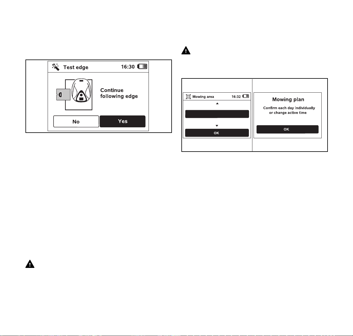
10 Installing the Robotic Mower
English
► Remove all obstacles from the perimeter and adjust the
perimeter wire as necessary to ensure problem-free
operation.
To continue the test run after an interruption:
► Place the robotic mower on the perimeter wire or place it
within the mowing area facing the perimeter wire.
► Select Yes and press the OK button on the control panel /
manual controller.
After completing the test run, the robotic mower will dock
and then repeat the test in the opposite direction. After
completing the second test run, the robotic mower will dock
again and the next step of the installation assistant will be
called up. A successful perimeter wire test must be
completed for iMow to work properly.
NOTICE
STIHL recommends completing the full test run in both
directions.
10.8 Programming the Robotic Mower: the Mowing Plan
WARNING
The robotic mower can be programmed to cut autonomously
during specific blocks of time (active times). When utilizing
this feature, keep bystanders away from the mowing area.
Never allow the robotic mower to operate if you know that
animals or persons are or may be in the mowing area or
vicinity, @ 5.6.3.
WARNING
Observe all applicable laws, regulations, standards and
ordinances when programming active times. Set and adjust
active times after completing the initial installation, @ 14.6.
5000 ft²
6000 ft²
7000 ft²
0000-GXX-3368-A0
0000-GXX-3369-A1
► Select the size of your lawn and confirm it by pressing the
OK button on the control panel / manual controller.
Installed restricted areas and secondary areas must not
be included when calculating the size of the mowing area.
The robotic mower automatically calculates a mowing plan
accounting for the size of the lawn and the length of the
perimeter wire.
When the robotic mower has finished calculating the mowing
plan, the display shows the message "Confirm each day
individually or change active time."
► To end the calculation of the mowing plan, push the STOP
button.
► Press the OK button on the control panel / manual
controller to approve or change the active times. Before
modifying active times, see @ 14.5.
The active times for Monday are displayed and the menu
item "Confirm active times" is highlighted.
0478-131-8246-A
31
Page 34

English
0000-GXX-3371-A0
► Confirm all active times by pressing the OK button on the
control panel / manual controller. The display will show the
next day's mowing plan for you to approve or modify.
In the case of small mowing areas, mowing may not be
scheduled every day. In this case, no active times are
displayed and the menu item "Delete all active times" is
not available. Days without active times must also be
confirmed by pressing the OK button on the control panel
/ manual controller.
Next to each menu item, one of the following symbols is
displayed:
The displayed active times can be changed. Select
the time interval to be changed using the navigation
pad and open it by pressing the OK button on the
control panel / manual controller, @ 14.6.
Additional active times can be programmed. Select
the menu item "New active time" and open it by
pressing the OK button on the control panel / manual
controller.
Select up to three active times per day with their start
and end times in the selection window. Confirm it by
pressing the OK button on the control panel / manual
controller.
Active times can be deleted. Select the menu item
"Delete all active times" and confirm it by pressing the
OK button on the control panel / manual controller.
10 Installing the Robotic Mower
To complete programming:
0000-GXX-3370-A0
► Confirm the active times for Sunday.
The final mowing plan will be displayed.
► Confirm the displayed mowing plan by pressing the OK
button on the control panel / manual controller.
The final step of the installation assistant will be called up.
► Select "Change" if you need to modify one of the active
times.
Before changing the active times or mowing duration on your
iMow, see the chapters on the Mowing Plan, @ 14.5,
@ 14.6 and @ 14.7.
NOTICE
If you have a sprinkler system, program the robotic mower
to avoid active watering times in order to reduce the
likelihood of damage to the sprinkler heads from contact with
the mowing blade. The mower and sprinkler system should
never be run at the same time.
NOTICE
Avoid contacting the perimeter wire when de-thatching or
aerating the lawn. Also use caution when operating a line
trimmer near the perimeter wire. De-thatching, aerating and
trimming operations can result in a cut or damaged
perimeter wire. Refer to your sketch of the mowing area and
take special care to avoid the perimeter wire when
performing these operations.
32
0478-131-8246-A
Page 35

11 Installing the Perimeter Wire
0000-GXX-3372-A0
English
10.9 Completing the Initial Installation and First Mowing Operation
WARNING
Inspect the mowing area. Just as you would before starting
a mowing operation with a traditional lawn mower, remove
all sticks, stones, pieces of metal, glass, wire or other
objects that could be thrown or flung by the cutting
attachment, damage the cutting attachment or cause
damage to property (e.g., parked vehicles, windows).
Remove objects from the mowing area such as toys, balls,
lawn furniture, landscape ornaments, flower pots, garden
hoses, lawn equipment and anything else that could impede
the proper operation of the robotic mower or become
entangled in its mowing blade.
► Complete the initial installation by pressing the OK button
on the control panel / manual controller.
If you complete the initial installation during an active time,
the robotic mower will immediately begin to mow.
If you complete the initial installation outside an active time,
you can start a mowing operation by pressing the OK button
on the control panel / manual controller.
► If you do not want the robotic mower to mow immediately,
select "No" and press the OK button on the control panel /
manual controller.
11 Installing the Perimeter Wire
11.1 Planning the Layout of the Mowing Area
When planning the layout of the mowing area and placement
of the perimeter wire:
► Study the installation examples at the end of this
instruction manual, @ 25. Consider restricted areas,
corridors, secondary areas, search loops and reserve wire
in your planning to prevent or minimize the need for
subsequent re-routing and adjustment of the perimeter
wire.
► Determine the location of the docking station, @ 10.3.
► Remove obstacles from the mowing area and create
restricted areas as necessary, @ 11.5.
► Join all parts of the mowing area by planning and installing
corridors or secondary areas, @ 11.7 and @ 11.6.
► Plan search loops if you use an external docking station or
the offset drive home feature, @ 11.8.
► Plan locations for reserve wire at several points to make it
easier to subsequently adjust or modify the path of the
perimeter wire, @ 11.12.
When installing the perimeter wire:
► Use only perimeter wire and wire stakes authorized by
STIHL.
► Install the perimeter wire in a continuous loop around the
entire mowing area with a maximum length of 1640 ft.
(500 m).
► If you install the perimeter wire around areas smaller than
430 sq. ft. (40 m²), the STIHL Small Area Module
AKM 100 (special accessory) must also be installed. For
more information, contact your authorized STIHL iMow
servicing dealer.
► Observe the specified wire clearances for each type of
installation (restricted areas, corridors, etc.). Measure the
clearances using the STIHL Ruler, @ 11.3.
0478-131-8246-A
33
Page 36

English
11 Installing the Perimeter Wire
► Avoid creating angles less than 90°. These will be difficult
for the robotic mower to navigate, and could result in
unmowed areas.
► If burying the perimeter wire, place it at a depth of no more
than 3.9 in. (10 cm).
Burying the perimeter wire in the ground may influence
signal reception, particularly if flagstones or paving stones
are laid over the perimeter wire. The robotic mower may
then travel along at a greater offset to the perimeter wire,
requiring more space in corridors, confined areas and when
traveling along edges. Adjust the location and depth of the
perimeter wire if necessary.
NOTICE
Avoid contacting the perimeter wire when de-thatching or
aerating the lawn. Also use caution when operating a line
trimmer near the perimeter wire. De-thatching, aerating and
trimming operations can result in a cut or damaged
perimeter wire. Refer to your sketch of the mowing area and
take special care to avoid the perimeter wire when
performing these operations.
11.2 Making a Sketch of the Mowing Area
STIHL recommends making a sketch of the mowing area
that includes the following:
– The contour of the mowing area including important
obstacles, borders and any restricted areas which the
robotic mower must not mow, @ 25.
– The location and position of the docking station, @ 10.3.
– The location of the perimeter wire and any wire
connectors you have installed, @ 10.4.
– If you change the dimensions of your mowing area after
the initial setup (by adding sections or moving the
perimeter wire, for example), re-link the iMow to the
docking station (@ 10.6) and run the test edge function
(@ 15.3) to measure the length of the perimeter wire and
develop a new mowing plan.
11.3 Measuring Wire Clearances with the STIHL Ruler
1
0000-GXX-3391-A0
The perimeter wire (1) can be routed next to surfaces such
as patios and paths as long as the surface is flat, level with
the grass, and allows the robotic mower to travel unimpeded
by obstacles. If necessary, the robotic mower may travel
with one rear wheel outside the mowing area. The maximum
height difference between lawn area and obstacle must not
exceed 0.8 in. (2 cm).
A
B
D
C
0000-GXX-3392-A0
The STIHL Ruler is designed to help you maintain the proper
the clearances when installing the perimeter wire. It will help
you quickly and easily measure the following distances:
34
0478-131-8246-A
Page 37

11 Installing the Perimeter Wire
English
A = 3.9 in. (10 cm)
Increased wire clearance for routing the
perimeter wire around a corner with an obstacle
above the mowing surface, @ 10.4.
Wire clearance for funnel-shaped routing of the
perimeter wire at the start and the end of a
corridor, @ 11.7.
B = 6.7 in. (17 cm)
Wire clearance for funnel-shaped routing of the
perimeter wire at the start and end of a corridor,
@ 11.7.
C = 10.6 in. (27 cm)
Minimum distance to be maintained between an
obstacle and the perimeter wire.
Wire clearance for routing corridors, @ 11.7.
To ensure that the robotic mower runs without contacting
any obstacle:
C
► Keep a minimum clearance of C = 10.6 in. (27 cm) from
obstacles.
► If routing the perimeter wire in confined areas, keep a
minimum clearance of two times the length C of the STIHL
Ruler (21.3 in. (54 cm)), @ 11.4.
D = 0.8 in. (2 cm)
Maximum height difference the robotic mower
can cross.
0000-GXX-3394-A0
If the height difference between the grass and other surface
(e.g., path, patio) is less than 0.8 in. (2 cm), you may install
the perimeter wire adjacent to the other surface:
► Route the perimeter wire without clearance to the
obstacle.
► Take care to avoid damaging the perimeter wire when
using a line trimmer or edging in that area.
► If necessary, install the perimeter wire at a slight distance
of 0.8 in. to 1.2 in. (2 cm to 3 cm) from the lawn edge.
0478-131-8246-A
0000-GXX-3393-A0
35
Page 38

English
c
a
c
bb
0000-GXX-3396-A0
b
a
a
a
a
a
a
1
0000-GXX-3397-A0
► If the height difference between the surfaces is more than
0.8 in. (2 cm), route the perimeter wire at minimum
distance of C = 10.6 in. (27 cm) from the other surface or
obstacle.
11.4 Routing the Perimeter Wire in Confined Areas
The robotic mower can travel automatically though narrow
passages, provided required minimum wire clearances are
maintained.
11 Installing the Perimeter Wire
► If you route the perimeter wire in a confined area,
deactivate the offset drive home function, @ 15.3.
11.5 Routing Around Restricted Areas
A restricted area is an area that the robotic mower must
avoid, including obstacles that cannot be mowed or objects
that the mower can't bump off of to change direction, such
as flower beds, trees with buttressed roots, etc.
► Install a restricted area around such obstacles.
0000-GXX-3395-A0
► Keep a minimum clearance of a = 21.3 in. (54 cm)
between the perimeter wire routed around a restricted
area and the perimeter wire at the edge of the mowing
area.
► Keep a minimum clearance of at least b = 6.6 ft. (2 m)
around the docking station (1).
► If you route the wire between obstacles higher than 0.8 in.
(2 cm), e.g. walls or hedges, keep a minimum wire
clearance of b = 6.7 in. (17 cm).
► If you route the wire between obstacles lower than 0.8 in.
(2 cm), e.g. paths or patios, keep a minimum wire
clearance of c = 21.3 in. (54 cm).
► Block off narrower areas in which a < 42.5 in. (108 cm)
through appropriate routing of the perimeter wire.
36
3
4
c
2
► Route the perimeter wire from the edge to the obstacle
with the proper clearance.
0000-GXX-3398-A2
0478-131-8246-A
Page 39

11 Installing the Perimeter Wire
1
A
B C
2
2
0000-GXX-3399-A0
English
► Route the perimeter wire around the obstacle (2) and
attach it to the ground using a sufficient number of wire
stakes (3).
► Then route the perimeter wire back to the edge again. The
segment of perimeter wire routed back to the edge (4)
must be laid directly next to the segment leading to the
restricted area. When the wire is laid side-by-side, the
signal is canceled and the iMow will ignore this section of
perimeter wire and mow directly over it. If the wires are
separated, however, the iMow will not traverse the wire
and the area between the two segments of perimeter wire
will not be mowed.
► After routing the perimeter wire back to the edge, do not
cross the sections of the perimeter wire. Continue the
installation around the perimeter of the mowing area. The
perimeter wire must exit the restricted area in the direction
opposite to the direction in which it entered the restricted
area, @ 11.9.
► If you route the perimeter wire around very small
obstacles, e.g. around an individual tree, keep a minimum
clearance of at least c = 14.6 in. (37 cm, clearances A and
C on the STIHL Ruler).
NOTICE
STIHL recommends checking the proper installation of
restricted areas after the initial installation or after changes
to the wire installation using the "Test edge" command,
@ 14.3.
11.6 Installing Linked Areas and Secondary Areas
Linked areas (B) and secondary areas (C) are parts of the
mowing area that are not located in the primary mowing
area (A) where the docking station (1) is located.
A secondary area is an area that iMow cannot physically
drive to. It cannot be mowed automatically. The robotic
mower must be picked up and carried to the secondary area
and brought back to the primary area when mowing is
complete.
Linked areas (B) can only be mowed automatically if they
are linked by corridors or linking sections.
► Route the perimeter wire (2) in the same direction in all
linked areas and secondary areas.
► Connect the linked areas to the primary mowing area by
installing corridors (@ 11.7) or linking
sections (@ 11.9). Never cross perimeter wires in the
linking areas. Keep them parallel.
► Activate secondary areas in the "Settings – Installation"
menu, @ 15.3.
11.7 Installing Corridors
A corridor joins a linked area to the primary mowing area,
e.g. a mowing area in front of and behind the house. This
allows both mowing areas to be mowed automatically.
In corridors, the lawn is only mowed along the path of the
perimeter wire. In order for the iMow to mow the linked area,
a starting point in the linked area must be defined.
In corridors, the lawn is only mowed along the path of the
perimeter wire.
0478-131-8246-A
37
Page 40

English
A
B
1
0000-GXX-3401-A0
1
B
A
4 4
2
3
0000-GXX-3400-A1
To install a corridor:
► Remove stones, pieces of metal, glass, wire or other
objects that could be thrown or flung by the cutting
attachment.
a
2
11 Installing the Perimeter Wire
1
C
c
d
b
1
1
b
► Keep a minimum clearance between obstacles higher
than 0.8 in. (2 cm) of a = 42.5 in. (108 cm).
► Keep a minimum clearance between obstacles lower than
0.8 in. (2 cm), paths/obstacles that can be travelled on, of
b = 10.6 in. (27 cm).
► Route the perimeter wire (1) parallel to the ground and
attach it to the ground with a sufficient number of wire
stakes (2).
► Alternatively, use the tunnel-shaped STIHL Corridor
Pattern (C) to install the a gate at each end of the corridor.
► When using the "Passage" feature, search loops must be
0000-GXX-3402-A0
installed in the linked area in order for the iMow to be able
to locate the gate and return to the docking station,
@ 15.3.
► Define at least 1 starting point in the linked area, @ 15.6.
► If necessary, activate automatic edge mowing or mow the
corridor area manually on a regular basis, @ 14.3 and
@ 15.3.
Corridor Installation Example
0000-GXX-5414-A0
► Install a gate, which is a funnel-shaped entrance and exit
area at each end of the corridor. Keep the following
distances:
– A = 3.9 in. (10 cm)
– B = 6.7 in. (17 cm)
38
The docking station (1) is installed in the primary mowing
area (A). A linked mowing area (B) is linked to the primary
mowing area with a corridor (2). The perimeter wire (3) can
be followed by the robotic mower. To ensure mowing of the
linked mowing area, two starting points (4) were defined.
0478-131-8246-A
Page 41

11 Installing the Perimeter Wire
11
aa
0000-GXX-3404-A0
aa
11
0000-GXX-3405-A0
English
11.8 Installing Search Loops
To help the robotic mower recognize the location of an
external docking station or a corridor, or if the "Passage"
function is activated, search loops should be installed. If it
crosses one of these search loops during its drive home, the
robotic mower will then directly travel to the perimeter wire
and to the docking station or through the corridor.
To install a search loop:
1
a
1
1
A
C
b
A
a
d
► Keep a minimum clearance of a = 6.6 ft. (2 m) from the
corners of the mowing area.
► Install the perimeter wire (1) with a minimum length of
b = 3.3 ft. (1 m) and with a distance of d = 0.4 in. (1 cm) in
between.
► Fasten the perimeter wire to the ground with two wire
stakes at the edge (A). Do not cross the perimeter wires.
Keep them parallel.
► Attach the search loop to the ground with a sufficient
number of wire stakes.
To install a search loop in combination with an external
docking station:
► Install two search loops (1), each at a 90° angle on the left
and right side of the docking station.
► Keep a minimum clearance of a = 6.6 ft. (2 m) from the
docking station.
To install a search loop in combination with a corridor:
0000-GXX-3406-A1
0478-131-8246-A
► Install two search loops (1) at an angle of 90° in the part
of the mowing area that can only be reached via a corridor.
► Keep a minimum clearance of a = 6.6 ft. (2 m) from the
corridor entrance.
39
Page 42
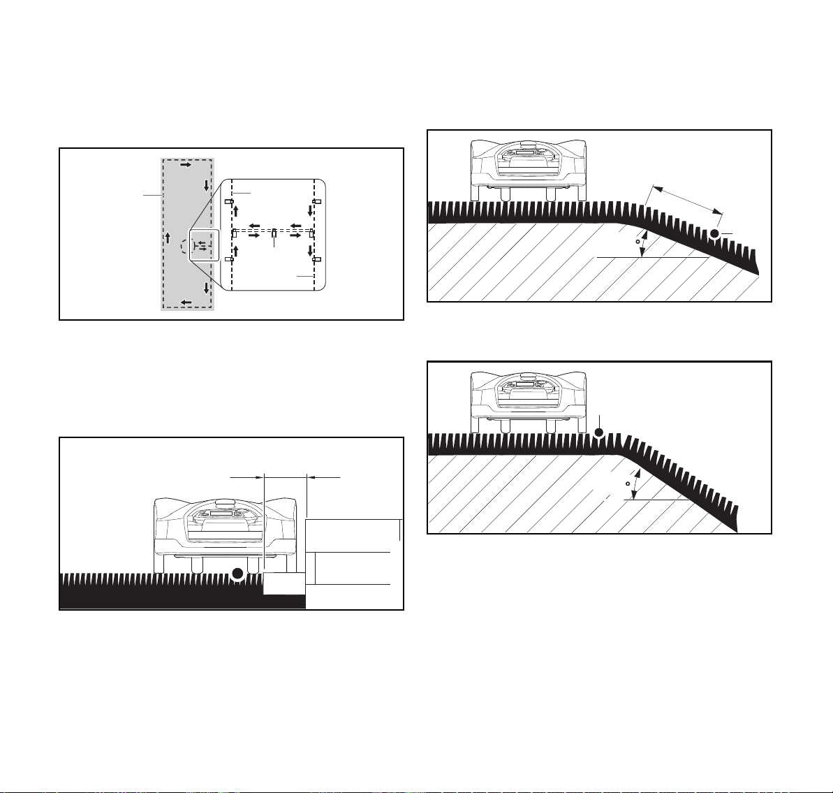
English
1
1
2
1
0000-GXX-3403-A0
a
0000-GXX-3407-A0
1
15
0000-GXX-3409-A1
11 Installing the Perimeter Wire
11.9 Installing Linking Sections
A linking section links a secondary area to the primary
mowing area, e.g. a mowing area in front of and behind the
house that the iMow cannot travel to on its own. This allows
both mowing areas to be mowed automatically.
► Route the perimeter wire (1) parallel and close to one
another.
► Attach the linking section to the ground with a sufficient
number of wire stakes (2).
11.10 Accurate Mowing Along Edges
11.11 Sloping Terrain in the Mowing Area
To install the perimeter wire at a slope with an incline of 5°
to 15°:
a
1
5-15
0000-GXX-3408-A0
► Route the perimeter wire (1) past the top edge of the
slope, keeping a minimum clearance of a = 19.7 in.
(0.5 m).
► Along high obstacles, route the perimeter wire with a
minimum clearance of 7.9 in. (20 cm) from the obstacle.
This buffer area will be left unmowed.
To reduce the buffer area which will be left unmowed, you
can lay edging stones or pavers around high obstacles, e.g.
walls.
40
► If the incline of the slope exceeds 15°, route the perimeter
wire in the flat area before the top edge of the slope. The
top edge of the slope and the slope itself should be
excluded from the mowing area.
11.12 Installing Reserve Wire
Installing reserve lengths of perimeter wire at regular
intervals near difficult passages will make it easier to modify
the installation of the perimeter wire or docking station if that
should become necessary.
0478-131-8246-A
Page 43

11 Installing the Perimeter Wire
a
1
0000-GXX-3410-A0
To install reserve wire:
► Route the perimeter wire (1) between 2 wire stakes
spaced approximately a = 3.3 ft. (1 m) apart.
► Attach the reserve wire to the ground in the centre using a
further wire stake.
11.13 Using Wire Connectors
WARNING
To reduce serious or fatal injury or property damage from
fire or electric shock, use only wire connectors authorized by
STIHL.
Wire connectors are designed to link two loose ends of
perimeter wire to extend the perimeter wire or to connect
loose wire ends caused by a breakage, for example. They
are filled with gel to prevent premature wear, e.g. corrosion
of the wire ends.
► Make a note of the positions of the wire connectors on
your sketch of the mowing area, @ 11.2.
English
1
2
0000-GXX-3411-A1
► Insert the unstripped wire ends (2) in the wire
connector (1).
► Press the wire connector together using suitable pliers.
a
0000-GXX-3412-A1
► Attach the perimeter wire to the ground using two wire
stakes, leaving a = 2 in (5 cm) of strain relief as depicted
above.
0478-131-8246-A
41
Page 44

English
1
0000-GXX-3341-A0
1
0000-GXX-3341-A0
12 Docking Station
12 Docking Station
12.1 LED on the Docking Station
A red LED (1) shows the status of the docking station and
the perimeter wire signal.
If the LED is off: The docking station is switched off and the
wire signal is not being transmitted.
If the LED glows: The docking station is switched on and the
robotic mower is not docked.
If the LED flashes slowly: The docking station is switched
on, the robotic mower has docked successfully or is being
charged.
If the LED glows for 3 seconds followed by a 1 second
pause: The "Homecall" function is activated.
If the LED flashes rapidly (approximately two times per
second): The perimeter wire is not correctly connected to the
docking station or the wire signal is no longer present. The
perimeter wire may be broken (wire break).
If the LED flashes rapidly at intervals: The LED flashes
alternately 3 times at a 1- second interval, 3 times at a 2second interval, 3 times at a 1-second interval, 5 second
pause. After the pause, the signal is repeated. The docking
station has a malfunction. For troubleshooting information,
@ 21.
12.2 Docking Station Controls
ON/OFF/Home button
Press and hold the ON/OFF/Home button for 2
seconds during a mowing operation to switch off the
wire signal. The robotic mower will stop, remain in the
mowing area and a corresponding message will
appear in the display of the robotic mower.
Press the ON/OFF/Home button twice within 2
seconds during a mowing operation to bring back the
robotic mower to the docking station (Homecall).
The robotic mower will end its current mowing
operation, search for the perimeter wire and return to
the docking station to recharge the battery. The
robotic mower will not start any further mowing
operation during the current active time. A Homecall
remains active until the robotic mower is docked or
until you press the ON/OFF/Home button twice for a
second time.
12.3 Docking the Robotic Mower
Automatic docking
The robotic mower will travel to the docking station
automatically and dock when the active time ends or the
robotic mower needs to be recharged.
42
0478-131-8246-A
Page 45

12 Docking Station
English
Docking with the Homecall function
The robotic mower can be called back to the docking station
manually. To call the robotic mower back:
► Press the ON/OFF/Home button on the docking station
twice within 2 seconds.
The robotic mower will return to the docking station and
will not start any further mowing operation during the
current active time.
Manual docking
► Remove the control panel / manual controller and activate
the Hand control command, @ 16.4 and @ 14.3.
► Steer the robotic mower to the docking station using the
control panel / manual controller or activate the disabling
device and transport the robotic mower to the docking
station by hand, @ 17.
1
► Lift the robotic mower slightly by the carrying handle (1)
and relieve the weight on the drive wheels.
► Push the robotic mower, resting on its front wheels, into
the docking station.
► Insert the control panel / manual controller, @ 16.4.
12.4 Charging the Robotic Mower
WARNING
Read and follow the robotic mower and docking station
safety precautions and instructions in this manual, @ 5.4
and @ 6. Be alert for signs that the integrated battery may
be damaged. To reduce the risk of personal injury from short
circuit, fire and explosion, never use or charge a robotic
mower if the hood or housing is cracked, deformed or
excessively hot, if battery fluid is leaking from the battery
compartment, or if the battery is otherwise damaged,
@ 5.5.
WARNING
To reduce the risk of electric shock, charge the robotic
mower only in the docking station. Do no remove the battery
or attempt to charge it using an external charger.
Automatic charging
The robotic mower will begin charging automatically when it
docks in the docking station at the end of the mowing
operation and its energy level is below a certain value.
Starting charging manually
To start charging:
► Dock the robotic mower.
► If necessary, end standby mode of the robotic mower by
pressing any button.
Charging will start automatically.
During charging, the display will show the message
"Charging battery" in the status screen.
0000-GXX-3390-A0
In all the other menus, the display will show a plug
symbol to indicate that the robotic mower is charging.
Charging time depends on a number of factors, including
battery condition and the ambient temperature. Exposure to
direct sunlight can lead to increased temperatures inside the
machine and battery compartment, which can increase
battery charging times.
Charge status
The current state of charge is indicated in the status
screen.
In all the other menus, the display will show a battery
symbol to indicate the robotic mower's charge status.
0478-131-8246-A
43
Page 46

English
If you end standby mode of the robotic mower by pressing
any button, but the state of charge is too low for the robotic
mower to return to the docking station, this symbol is display
over the entire screen. After a few seconds, the display will
turn off and the robotic mower will return to standby mode.
13 Control Panel / Manual Controller
Display Information
13.1 Information Area
13 Control Panel / Manual Controller Display Information
2. Automatic mowing status
When automatic mowing is switched on, the
Automatic symbol appears.
3. Charge status
The battery symbol shows the battery's state of charge. For
example:
– No bars: battery discharged
0000-GXX-3878-A00000-GXX-5340-A0
– 1 to 5 bars: battery partially discharged
– 6 bars: full charge.
During charging, the plug symbol is displayed instead
of the battery symbol.
13.2 Status Screens
Different status screens may appear, depending on the
status of the robotic mower.
► Configure the status screen with various information,
@ 15.2.
Status screen when the robotic mower is not in operation
The following information is shown in the top right corner of
the display:
1. Time
The current time is indicated in 24 hour format.
44
0000-GXX-3377-A0
The text "iMow ready for op." and the automatic mowing
status is displayed in the bottom area of the screen.
There are two configurable fields in the top display area.
0478-131-8246-A
Page 47

14 Menu Functions
0000-GXX-3379-A0
0000-GXX-3380-A0
0000-GXX-3375-A0
English
Status screen during operation
The text "Attention – iMow starting" and the safety alert
symbol are displayed before a mowing operation starts.
Flashing of the display illumination and a signal tone
additionally indicate the start of the mower.
Battery charging: The text "Charging battery"
appears during charging.
Status screen for messages
If an error or fault occurs during operation, a message will be
displayed that includes the date and time of its occurrence
and the relevant message code. If several messages apply,
they appear alternatively, @ 21.1.
14 Menu Functions
14.1 Navigating the Menus
The text "iMow mowing lawn" and a corresponding symbol
are displayed during an active mowing operation. The text
and symbol will depend on the specific active operation.
Edge mowing: While the robotic mower mows the
edges of the mowing area, the text "Mowing edge" is
displayed.
Drive to docking station: When the robotic mower
returns to the docking station, the relevant reason is
indicated in the display (e.g., "Battery discharged" or
"Mowing completed").
0478-131-8246-A
0000-GXX-3378-A0
► Select a submenu using the navigation pad.
If a submenu is selected, it is displayed on a black
background.
45
Page 48

English
0000-GXX-3594-A0
0000-GXX-3595-A0
14 Menu Functions
► Open the selected submenu by pressing the OK button.
In the second menu level, the various submenus are
shown as tabs.
► Select a tab by pressing the navigation pad to the left or
right.
► Select a submenu by pressing the navigation pad
downwards or upwards.
Selected tabs and submenu entries are displayed on a
black background.
► If there is a scroll bar at the right edge of the display,
display further entries by pressing the navigation pad
downwards or upwards.
► Press the OK button to open a submenu.
Options are listed in the submenus. Selected entries are
displayed on a black background.
► Press the OK button to open a selection window or dialog
window.
Selection window
The selected value is displayed on a black background.
► Navigate through the values and change them by using
the navigation pad.
► Press the OK button to confirm your selections.
Dialog window
0000-GXX-3376-A0
46
If changes have to be saved or messages confirmed, a
dialog window appears in the display. The selected button is
displayed on a black background.
► Press the OK button to confirm the selection.
0478-131-8246-A
Page 49

14 Menu Functions
0000-GXX-3382-A0
0000-GXX-3383-A0
English
14.2 Overview
The main menu contains 4 submenus. The main
menu will be displayed,
– when the status screen (@ 13.2) is quit by
pressing the OK button,
– when the "Main menu" command is activated,
– when the Back button is pressed in the second
menu level.
Commands
This submenu contains a set of autonomous mowing
operations, @ 14.3.
Information
This submenu contains information about the lawn or
the robotic mower's status, @ 14.4.
Mowing plan
This submenu contains functions to change the
mowing plan, @ 14.5.
Settings
This submenu contains functions to change the
robotic mower's settings, @ 15.2.
14.3 Commands
► Select a tab by pressing the navigation pad to the left or
right.
► Press the OK button to open the submenu.
Main menu
Select to return to the main menu.
Lock robotic mower and activate disabling device
Select to return to lock the robotic mower and activate
the disabling device.
Switch automatic mowing on/off
Select to turn automatic mowing on or off.
When automatic mowing is switched on, the text
"Automatic switched on" appears in the status screen
and the symbol is displayed next to the battery
symbol.
When automatic mowing is switched off, the text
"Automatic switched off" appears in the status screen
and the active times are shown as inactive (greyed
out) in the mowing plan.
0478-131-8246-A
47
Page 50

English
14 Menu Functions
Drive to docking station
Select to command the robotic mower to drive to the
docking station immediately.
The robotic mower travels back to the docking station
and charges its battery. If automatic mowing is
switched on, the robotic mower will start to mow the
mowing area again at the next possible active time.
Hand control
Select to activate manual lawn mowing.
Use the navigation pad to steer the robotic mower,
@ 16.5.
Start mowing
Select to start the mowing operation immediately.
If a secondary area was installed, press the OK
button and then specify whether the mowing
operation is taking place in a secondary area or in the
main area, @ 16.7.
If an external docking station with a corridor was
installed, bring the robotic mower to the mowing area
before activation of the command "Start mowing."
You will be prompted to enter the time to end the
mowing operation. The default setting for the duration
of the mowing operation can be modified under
"Mowing time" in the machine settings, @ 15.
Mowing time in primary or linked areas following the
"Start mowing" command will be deducted from the
weekly mowing plan's total mowing duration.
Start time-delayed mowing
Select to set a defined time to start the mowing
operation.
If a secondary area was installed, after pressing the
OK button it is necessary to define whether the
mowing operation is taking place on a secondary
area or on the main area, @ 16.7.
If an external docking station with a corridor was
installed, bring the robotic mower to the mowing area
before activation of the command "Start time-delayed
mowing".
You will be prompted to enter the time to end the
mowing operation. The default setting for the duration
of the mowing operation can be modified under
"Mowing time" in the machine settings, @ 15.
Mowing time in primary or linked areas following the
"Start time-delayed mowing" command will be
deducted from the weekly mowing plan's total
mowing duration.
Skip next active time
Select to skip the next active time.
No mowing will take place during the next active time.
Active times which have been cancelled in this
manner are greyed out in the mowing plan. They can
be released for mowing again in the "Daily plan"
menu, @ 14.6.
If the command is performed several times in
succession, the next active time is always skipped. If
no active times remain for the current week, the
message "No mowing will take place next week"
appears.
48
Edge mowing
Press the OK button to mow the edge of the mowing
area.
After completing one circuit, the robotic mower
travels back to the docking station and charges the
battery.
0478-131-8246-A
Page 51

14 Menu Functions
0000-GXX-3388-A0
English
14.4 Information
Messages
This submenu contains a list of all active errors, faults
and recommendations including date and time of
their occurrence and the respective message code.
Press the OK button to display details for every
message, @ 21.1.
If no messages are available, this display shows the
text "No messages."
Events
This submenu contains a list of the last activities of
the robotic mower. Details of the events (additional
text, time and code) can be displayed by pressing the
OK button.
Errors during normal operation are documented in
the messages.
Robotic mower status
This submenu contains information on the robotic
mower's status:
– Charging status: Battery charging status in percent
– Rem. time: The remaining mowing duration during
the current week in hours and minutes
– Time and date
– Start time: Start of the next planned mowing
operation
– Total number of completed mowing operations
– Mowing hours: Duration of all completed mowing
operations in hours
– Distance: Total distance covered in meters
– Ser.-No.: Serial number of the robotic mower. This
is also to be found on the identification plate in the
compartment beneath the control panel / manual
controller.
– Battery: Serial number of the battery
– Software: Installed machine software
Lawn information
This submenu contains information on the lawn:
– Mowing area in square meters: This measurement
is taken during installation
– Round time: Duration of one circuit around the
mowing area in minutes and seconds
– Starting points 1 – 4: Distance of the relevant
starting point from the docking station in meters,
measured in a clockwise direction
– Circumference: Circumference of the mowing area
in meters
– Edge mowing: Frequency of edge mowing per
week
0478-131-8246-A
49
Page 52

English
0000-GXX-3384-A0
14 Menu Functions
14.5 Mowing Plan
Mowing Plan Theory of Operation
Before changing your mowing plan, read the following
section carefully. There are two components to the mowing
plan: mowing duration and active times. The STIHL iMow
mowing plan is designed to be flexible. For best results, the
ratio between mowing duration and active time that is
developed during the initial setup of your iMow should be
maintained.
During the initial setup, the iMow will automatically calculate
an appropriate automatic mowing plan. That plan consists of
active times and a weekly mowing duration. Active times are
those windows of time in which the iMow is programmed to
mow automatically. The iMow will only mow in automatic
mode during the active times. The mowing duration is the
total number of hours the iMow will mow per week.
Satisfactory cutting results depend on the iMow having
sufficient mowing duration and sufficient active times to
complete the mowing operation for the entire lawn.
Automatic mowing will cease once the iMow has reached its
total allotted mowing duration for the week, even if there are
remaining active times scheduled.
The active times and mowing duration must be set properly
to ensure that a sufficient number of mowing hours are set
each week (mowing duration) and that the iMow has
sufficient windows of time (active times) to complete the
mowing. If you increase the mowing duration, be sure
expand the active times as well to accommodate the
increased number of mowing hours. The total weekly active
time must be higher than the total weekly mowing duration
in order to account for charging time and to provide a buffer
in case active times are missed due to rainfall.
The status screen displays the remaining mowing duration
for the week and the next scheduled active time.
Mowing Plan Menu
Call up the stored mowing plan in the "Mowing plan"
submenu.
The rectangular blocks displayed in black beneath the days
of the week represent the saved active times. When
automatic mowing is turned on, mowing operations take
place only during active times. The iMow will not mow during
all active times as the iMow may return to the docking station
if it starts raining or the iMow requires charging.
Blocks displayed in grey represent active times without
mowing operations, e.g. where the active time has been
deactivated by the operator or the active time has been
skipped, @ 14.3. When automatic mowing is turned off, the
entire mowing plan is deactivated and all active times are
shown in grey.
► Select an active time or the mowing duration by pressing
the navigation pad downwards or upwards.
► Open the respective settings by pressing the OK button.
If you want to edit the active times for an individual
day, press the navigation pad to the left or right to
select the day.
Select the "Active times" submenu and press the OK
button.
50
0478-131-8246-A
Page 53

14 Menu Functions
0000-GXX-3386-A0
English
14.6 Active Times
WARNING
Keep bystanders away from the mowing area during active
times. Never allow children to approach or play with the
robotic mower. Keep children out of the mowing area while
the mower is in operation. Never allow the robotic mower to
operate if you know that animals or persons are or may be
in the mowing area or vicinity.
Next to every active time, a symbol shows the current status
of the active time:
This symbol indicates that the active time is
activated. The robotic mower will mow automatically
according to the mowing plan.
This symbol indicates that the active time is
deactivated. The robotic mower will not mow during
this time.
If active times are not sufficient to allow for the necessary
mowing and charging operations, you can increase active
times or reduce the mowing duration. To edit the active
times:
Select the "New active time" menu item to add an
active time. An additional active time may not overlap
with other active times.
Up to 3 active times per day can be saved.
Select "Delete all active times" to delete all active
times on the selected day.
The robotic mower will no longer operate on this day.
Select "Active time on/off" to enable or disable the
selected time for automatic mowing.
0000-GXX-3385-A0
Select "Change active time" to change the time the
robotic mower will be mowing.
Select "Delete active time" to delete this specific
active time.
The robotic mower will no longer operate at this time.
NOTICE
If you have a sprinkler system, program the robotic mower
to avoid active watering times in order to reduce the
likelihood of damage to the sprinkler heads from contact with
the mowing blade. The mower and sprinkler system should
never be run at the same time.
0478-131-8246-A
51
Page 54

English
Change mowing duration
0000-GXX-3387-A1
0000-GXX-3389-A0
15 Settings
14.7 Mowing Duration
Select "Change mowing duration" to change the total
weekly mowing hours. The mowing duration set
during initial installation is based on the size of the
mowing area, but it can be increased or decreased in
this submenu.
Select "New mowing plan" to delete all currently
stored active times and to program a new mowing
plan. The step "Program the robotic mower" of the
installation assistant will be called up, @ 10.8.
If you are reprogramming the mowing plan during one of the
new mowing plan's active times, the robotic mower will begin
an automatic mowing operation after you confirm the new
mowing plan.
15 Settings
15.1 Settings Overview
The Settings menu contains 5 submenus, displayed as
buttons:
Robotic mower
Select this submenu to change the robotic mower's
settings, @ 15.2.
Installation
Select this submenu to change and test the
installation, @ 15.3.
52
Safety
Select this submenu to change the security settings,
@ 15.4.
Service
Select this submenu to confirm replacement of the
mowing blade. This will reset the internal blade
replacement counter. Also select this submenu to find
a wire break, @ 15.5.
0478-131-8246-A
Page 55

15 Settings
English
Dealer area
This code-protected submenu is accessible only by
your authorized STIHL iMow servicing dealer.
15.2 iMow Settings
Rain Sensor
Adjust the sensitivity of the 5-stage rain sensor.
To set the rain sensor:
► Press the navigation pad to the left or right. The current
value is displayed by means of a line diagram.
Select this option to allow mowing at higher moisture
levels. If the bar is moved all the way to the left, the
robotic mower will mow even when it is raining.
Select this option to allow mowing under ordinary
ambient conditions.
Select this option to allow mowing only at lower
moisture levels. If the bar is moved all the way to the
right, the robotic mower will only mow if the rain
sensor is completely dry.
Mowing Time
Set the default mowing time for the duration of a
mowing operation when activating automatic mowing
with the "Start mowing“ command, @ 14.3.
Delay
Set the length of the delay when activating the "Start
time-delayed mowing" command, @ 14.3.
To set the status screen:
► Select the left or right part of the screen using the
navigation pad and confirm your selection by pressing OK.
► For each part of the display, select one of the following to
appear on the status screen:
Charging status: The battery charging status in
percent will appear on the status screen.
Rem. time: The remaining mowing duration during
the current week will appear on the status screen.
Time and date: The current date and current time will
appear on the status screen.
Start time: The start of the next planned mowing
operation will appear on the status screen. During a
running active time, the text "active" will be displayed.
Mowing events: The total number of mowing
operations performed will appear on the status
screen.
Mowing hours: The total duration of all mowing
operations performed will appear on the status
screen.
Distance: The total distance traveled will appear on
the status screen.
Time
Set the current time.
Always set the correct time to ensure an accurate
mowing plan and to prevent automatic mowing at
unwanted times.
Status Screen
You can edit the status screen to display the
information you want to appear, @ 13.2.
0478-131-8246-A
Date
Set the current calender date.
Always set the correct date to ensure an accurate
mowing plan and to prevent automatic mowing at
unwanted times.
53
Page 56

English
15 Settings
Date Format
Set your desired date format.
Track offset
Change the robotic mower's standard 2.36 in. (6 cm)
offset from the perimeter wire to a smaller or larger
offset (1.18 in. to 3.54 in. (3 cm to 9 cm)).
To ensure optimal performance under the standard
setup instructions, STIHL recommends that you keep
the default track offset setting.
Language
Set the desired display language. The language
selected during initial installation is set as the default.
Contrast
Change the display's contrast.
15.3 Installation
Passage
The robotic mower can travel back to the docking station
with an increased offset to the perimeter wire.
► Ensure that the perimeter wire has been routed with a
clearance of at least 2 m at the narrowest sections.
► Activate the passage setting to change the way the robotic
mower travels back home to the docking station. Select
one of three options:
– Off (default setting): The robotic mower travels along
the perimeter wire.
– Narrow: The robotic mower travels along the perimeter
wire or with an offset of 15.7 in. (40 cm).
– Wide: The robotic mower travels within a passage of
15.7 in. to 31.5 in. (40 cm to 80 cm) from the perimeter
wire.
► If you have installed an external docking station or a linked
section using a corridor, install search loops for offset
drive home, @ 11.8.
ASM (Anti-Stuck-Maneuver)
The robotic mower starts an evasive routine if it becomes
stuck: ASM is switched on by default.
► Switched off ASM, if there are large, flat expanses in the
mowing area (e.g. asphalt driveways), if the robotic mower
often unexpectedly turns 90° during operation or if the
mower unexpectedly stops mowing and the display shows
the message "1131 - Stuck".
New installation
The current mowing plan will be deleted and the
installation assistant will start again.
Starting points
To set starting points, see @ 15.6.
Test edge
Start a test run for checking correct wire routing. The
step "Check installation" of the installation assistant
will be called up, @ 10.7.
► To check correct wire routing around restricted areas,
position the robotic mower in the mowing area with the
front facing the restricted area and start the test run.
Edge mowing
Select the mowing frequency for edges.
► Select one of three options:
– Never: The edges will never be mowed.
– Once (default): The edges will be mowed once a week.
– Twice: The edges will be mowed twice a week.
54
0478-131-8246-A
Page 57

15 Settings
English
Secondary areas
Enable or disable secondary areas.
► Activate to enable mowing of a secondary area.
15.4 Safety
Disab. device
To activate the disabling device in the "Settings"
menu, open the "Safety" submenu, select "Lock
iMow" and confirm by pressing the OK button.
To deactivate the disabling device, press the Mow
button and the OK button in the sequence illustrated
on the display. Once the disabling device is
deactivated, the robotic mower can be operated
again.
Level
Four security levels can be set. Various locks and
security devices are activated, depending on the
level.
► Select one of four options:
1)None: All functions of the robotic mower can be
accessed.
2)Low:
– Anti-theft alarm: If the mower is lifted or tilted for
longer than 10 seconds, the PIN query appears. If you
do not enter then PIN code within one minute, an
alarm sounds and automatic operation is switched off.
– Connection lock: The PIN code must be entered prior
to linking of the robotic mower and docking station.
– Reset lock: The PIN code must be entered prior to
resetting the machine to the factory defaults.
3)Medium:
– All of the features from the "Low" setting.
– Time lock: PIN code query for changing a setting if no
PIN code has been entered for more than one month.
4)High:
– All of the features from the "Medium" setting.
– Setting protection: The PIN code must be entered
before settings can be changed.
► Select the desired security level and confirm it by pressing
the OK button.
► If necessary, enter the 4-digit PIN code.
STIHL recommends that the "Low", "Medium" or "High"
security level be set.
Change PIN code
The 4-digit PIN code can be changed if necessary.
The "Change PIN code" menu item is only displayed
in the "Low," "Medium" or "High" settings.
► Enter the old PIN code and confirm it by pressing the OK
button.
► Enter the new 4-digit PIN code and confirm it by pressing
the OK button.
Take note of your PIN code and keep it in a safe place. If the
PIN code is entered incorrectly 5 times, automatic operation
is switched off and can only be restored with a master code
generated by your authorized STIHL iMow servicing dealer.
Start signal
The acoustic signal when the mowing blade is
activated.
Alarm signal
The acoustic signal when the robotic mower hits an
obstacle.
Menu signal
The acoustic indicator when you open a menu and
confirm a selection by pressing the OK button.
Child lock
If the impact sensor is triggered several times in succession
within a short time, the robotic mower and the mowing blade
will stop.
If the impact sensor is not triggered again, the robotic mower
will continue automatic mowing after a few seconds.
0478-131-8246-A
55
Page 58

English
15 Settings
Keylock
When the keylock is activated, the operator must
press and hold the Back button and then press the
forward navigation button on the navigation pad to
unlock the control panel / manual controller. The
keylock will be activated again 2 minutes after the last
button is pressed.
Link iMow and dock:
The mower and docking station must be linked if you
replace the docking station the robotic mower.
► Install the docking station and connect the perimeter wire,
@ 10.3 and @ 10.5.
1
► Lift the robotic mower slightly by the carrying handle (1)
and relieve the weight on the drive wheels. Push the
machine, resting on its front wheels, into the docking
station.
► After pressing the OK button, enter the PIN code.
The robotic mower will then search for the wire signal and
automatically save it for automatic operation. This process
may take several minutes, @ 10.6.
15.5 Service
Blade change
► After mounting a new mowing blade, confirm the
replacement of the mowing blade by pressing the OK
button.
Find wire break
► Activate the assistant to find a wire break by pressing the
OK button.
► Find the wire break, @ 21.3.
Reset settings
► Press the OK button and enter the PIN code.
The robotic mower will be reset to factory defaults and the
installation assistant will be started, @ 10.
15.6 Setting Starting Points
► Set starting points to target automatic mowing in a specific
part of your lawn. Starting points are used to access linked
areas that are only accessible via a corridor. Starting
points are used when parts of your lawn are not being
mowed frequently enough, sometimes because part of the
mowing area is accessible only through a corridor.
Starting points can be set in two different ways.
"Teaching-in" starting points
Press the OK button. The robotic mower will begin to
travel along the perimeter wire. If it is not docked, it
first travels to the docking station. All current existing
0000-GXX-3390-A0
starting points are deleted.
To teach-in up to 4 starting points:
► Save each starting point by pressing the OK button during
the robotic mower's travel.
► The teach-in procedure is interrupted automatically when
the robotic mower contacts obstacles along the perimeter
wire. If the teach-in procedure is interrupted automatically,
correct the position of the perimeter wire and remove any
obstacles along the cutting path or correct the installation
of the perimeter wire.
► If necessary, interrupt the teach-in procedure manually by
pressing the STOP button.
► Check the position of the robotic mower before continuing
the teach-in procedure. The robotic mower must either be
located on the perimeter wire or within the mowing area
facing the perimeter wire.
56
0478-131-8246-A
Page 59

16 During Operation
English
► The starting frequency defines how often a mowing
operation is to begin from a starting point. The default
setting is 2 of 10 mowing operations (2/10) at each starting
point. You can change the starting frequency as desired
after each teach-in.
► If the teach-in procedure has been ended prematurely,
send the robotic mower back the to docking station.
Setting starting points 1 to 4 manually:
Press the OK button. All current existing starting
points are deleted.
To manually set up to 4 starting points:
► Determine the distance of the starting points from the
docking station. The distance corresponds to that covered
from the docking station to the starting point in meters,
measured in a clockwise direction.
► Set a starting frequency between 0 of 10 mowing
operations (0/10) and 10 of 10 mowing operations (10/10).
The docking station is defined as starting point 0. Mowing
operations are started from the docking station as a
default.
16 During Operation
16.1 Automatic Mowing
WARNING
Keep bystanders away from the mowing area during active
times. Never allow children to approach or play with the
robotic mower. Keep children out of the mowing area while
the mower is in operation. Never allow the robotic mower to
operate if you know that animals or persons are or may be
in the mowing area or vicinity.
When automatic mowing is switched on, the robotic mower
independently leaves the docking station and mows the lawn
during the active times set by the operator, @ 14.6. The
number and duration of the mowing and charging operations
within the active times are determined automatically.
The mowing plan is determined based on the size of the
mowing area calculated during installation or during the
creation of a new mowing plan.
When you switch on automatic mowing, the display
shows the automatic mowing symbol next to the
battery symbol.
► Define starting points in linked areas to have the robotic
mower automatically mow linked areas.
► To end an active mowing operation manually, press the
STOP button on the robotic mower or press the ON/OFF/
Home button on the docking station twice at any time.
When the battery is discharged, the robotic mower
automatically returns to the docking station.
16.2 Mowing Duration
The mowing duration specifies how many hours per week
the robotic mower will mow the lawn. Charging time is not
included in the mowing duration.
During initial installation, the robotic mower automatically
calculates the mowing duration appropriate for your lawn
based on the specified size of the mowing area. The
calculation is based on a normal lawn under dry conditions.
To complete a mowing area of approximately 1076 sq. ft.
(100 m²), the robotic mower will need approximately 60
minutes on average.
► If necessary, extend or reduce the active times and
mowing duration, @ 14.6 and @ 14.7.
0478-131-8246-A
57
Page 60

English
16 During Operation
16.3 Adjusting the Cutting Height
WARNING
To reduce the risk of serious personal injury or death,
always press and hold the STOP button for 5 seconds to
activate the disabling device before adjusting the cutting
height of the mowing blade.
AB
1 1
To lower the cutting height (A):
► Press and turn the rotary knob (1) counterclockwise.
The marking (2) indicates the selected cutting height.
To raise the cutting height (B):
► Press and turn the rotary knob (1) clockwise.
The marking (2) indicates the selected cutting height.
8 different cutting heights can be selected:
– Level 1: 0.79 in. (20 mm)
– Level 2: 1.01 in. (25.7 mm)
– Level 3: 1.24 in. (31.4 mm)
– Level 4: 1.46 in. (37.1 mm)
– Level 5: 1.69 in. (42.8 mm)
– Level 6: 1.91 in. (48.5 mm)
– Level 7: 2.13 in. (54.2 mm)
– Level 8: 2.4 in. (60 mm)
2 2
NOTICE
To reduce the risk of damaging the robotic mower, never
attempt to lift, carry or transport the robotic mower by the
rotary knob. The rotary knob will come off the robotic mower
if pulled. This prevents the unit from being lifted and carried
by the rotary knob.
NOTICE
To avoid overloading the motor, avoid setting the cutting
height too low in tall grass. If the motor speed begins to slow,
raise the cutting height.
16.4 Removing and Mounting the Control Panel / Manual Controller
WARNING
0000-GXX-3342-A0
To help reduce the risk of serious personal injury or death
from unintentional starting, always press and hold the STOP
button for 5 seconds to activate the disabling device before
approaching the unit while it is operation.
The control panel / manual controller can be removed from
the robotic mower to manually mow or to change the
programming of the robotic mower.
Automatic operation of the robotic mower is only possible
when the control panel / manual controller is mounted
securely onboard the robotic mower.
58
0478-131-8246-A
Page 61

16 During Operation
1
0000-GXX-5342-A0
2
2
3
0000-GXX-5341-A0
English
To remove the control panel / manual controller:
► Press and hold the STOP button for 5 seconds.
► Lift the rear of the control panel / manual controller (1) and
remove it from the robotic mower.
The control panel / manual controller remains connected
to the robotic mower via a spiral cable.
To mount the control panel / manual controller:
► Press and hold the STOP button for 5 seconds.
16.5 Manual Mowing
WARNING
Always keep the robotic mower in front of you during manual
operation and maintain a sufficient distance from the mower
at all times to reduce the risk of personal injury from thrown
objects or blade contact with your feet or other parts of your
body.
WARNING
The impact sensor and edge detection features are disabled
during manual mowing. To reduce the risk of injury, keep
bystanders, especially children, and pets or other animals
out of the mowing area. Avoid directing the mower into
obstacles or over objects that may be thrown or flung by the
mowing blade.
To mow manually:
► Charge the battery if necessary, @ 12.4.
► Remove the control panel / manual controller, @ 16.4.
► Activate the "Hand control" command, @ 14.3.
1
► Stow the spiral cable in the housing compartment.
► Tilt the control panel / manual controller back slightly and
insert the tabs (2) into the recesses in the housing (3).
► Carefully press down on the front of the control panel /
manual controller until the unit is securely attached and
you hear an audible click.
0478-131-8246-A
2
0000-GXX-3593-A0
► Move and steer the robotic mower (2) using the navigation
pad on control panel / manual controller (1). Two forward
speeds are available:
– Slow: Press the navigation pad lightly
– Fast: Press the navigation pad firmly
59
Page 62

English
16 During Operation
To activate the mowing blade, press and hold the OK
button with your right thumb, then press the Mow
button with your left thumb. The mowing blade will
start to rotate and will continue rotating as long as the
Mow button is pressed.
► During manual mowing, keep the Mow button pressed
down with your left hand and operate the navigation pad
with your right hand.
► To deactivate the mowing blade, release the Mow button.
► Return the robotic mower to the docking station for
charging after manual mowing, @ 12.4.
16.6 Adjusting the Mowing Duration and Active
Times
During active times, the robotic mower leaves the docking
station and mows the lawn autonomously. During these
times, mowing operations, charging operations and rest
periods take place. The robotic mower automatically
distributes the mowing and charging operations between the
available time windows. Under certain circumstances (e.g.
when grass growth is slowed by weather conditions), not all
the active times may be necessary for optimal lawn care.
The active times and the mowing duration can be changed
manually. You can set up to 3 different active times per day,
@ 14.5.
► You may wish to change the mowing duration and active
times for one of the following reasons:
– Additional active times for further mowing operations
are necessary to complete the weekly mowing duration.
– The active times need to be modified in order to prevent
mowing during a particular time of day.
– Individual active times need to be omitted, because the
mowing area will be in use, e.g., for a backyard party.
► You may wish to extend the mowing duration and active
times for one of the following reasons:
– There are areas which are not mowed sufficiently, e.g
because the mowing area has several corners.
– Intensive grass growth during the growing period.
– Particularly dense lawn.
► You may wish to reduce the mowing duration and active
times when there is reduced grass growth due to heat,
cold or dryness.
► You must re-link the docking station and create a new
mowing plan if the size of the mowing area has been
changed or the docking station has been relocated.
16.7 Mowing Outside of Active Times
Mowing primary mowing areas
► In order to mow a part of the mowing area that can only be
reached via a corridor, carry or steer the robotic mower to
the linked area.
► For immediate mowing, call up the "Start mowing"
command or press the Mow button, @ 14.3.
The mowing operation starts immediately and continues
until the selected time.
► For time-delayed mowing, call up the command "Start
time-delayed mowing", @ 14.3.
The mowing operation starts at the selected start time and
continues until the selected end time.
► To end an active mowing operation manually, press the
STOP button on the robotic mower. To return the robotic
mower to the docking station, press the ON/OFF/Home
button on the docking station twice at any time.
Secondary areas
► Carry or steer the robotic mower to the secondary area.
► Activate the secondary area, @ 15.3.
► For immediate mowing, call up the "Start mowing"
command or press the Mow button, @ 14.3.
The mowing operation starts immediately and continues
until the selected time.
► For time-delayed mowing, call up the command "Start
time-delayed mowing", @ 14.3.
The mowing operation starts at the selected start time and
continues until the selected end time.
When the selected end time is reached, the robotic mower
travels to the perimeter wire and comes to a standstill.
60
0478-131-8246-A
Page 63

17 Transporting
English
► Return the machine to the docking station to recharge the
battery and confirm the displayed message, @ 21.1.
► To end an active mowing operation manually, press the
STOP button on the robotic mower.
If the robotic mower is discharged before the selected end
time, the mowing operation will be shortened accordingly.
17 Transporting
17.1 Transporting the Robotic Mower
When transporting the robotic mower:
1
► Always disable the robotic mower by pressing and holding
the STOP button for 5 seconds before lifting or
transporting.
► When transporting the robotic mower by hand, hold it by
the carrying handing (1) with the mowing blade pointing
away from you. Never attempt to carry the robotic mower
by its hood.
► When transporting the robotic mower in a vehicle, position
robotic and secure the mower to prevent turnover, impact
and damage. Fasten the machine using suitable fastening
materials (straps, ropes) (see illustration above).
► Secure any other components being transported (e.g.
docking station, small components) to prevent turnover,
impact and damage.
A Note on Battery Transport
The battery inside this robotic mower complies with the
requirements set forth in UN-Manual ST/SG/AC.10/11/
Rev.5/Part III, Subsection 38.3.
Commercial air, vessel and ground transportation of lithium
ion cells and batteries contained in equipment is regulated.
The battery inside this robotic mower is classified as a UN
3481, Class 9, packaging group II product. Shipping it
requires compliance with all applicable shipping regulations.
Check with the ground, vessel, air cargo or passenger airline
to determine if transport is prohibited or subject to
restrictions or exemptions prior to shipping or travel.
Normally, no further conditions have to be met by the user in
order to transport this robotic mower by road to the operating
site. Check and comply with any special regulations that
may apply to your situation.
18 Storing the Robotic Mower and
Docking Station
18.1 Robotic Mower
WARNING
After the mowing season is over, or any time the robotic
0000-GXX-3605-A0
mower is not available for mowing operations, store the
iMow indoors in a dry, secure place that is inaccessible to
children and other unauthorized users, @ 5.4. Improper
storage can result in unauthorized use and damage to the
robotic mower, @ 5.4. Never place or store objects on the
robotic mower.
WARNING
If the robotic mower is damp or wet, dry it thoroughly before
storing to reduce the risk of short circuit and electric shock,
@ 5.4.
WARNING
High temperatures may cause the integrated battery to
generate heat, rupture, leak, ignite or explode, resulting in
severe or fatal personal injury or property damage, @ 5.5.
Use and store the robotic mower only within an ambient
0478-131-8246-A
61
Page 64

English
18 Storing the Robotic Mower and Docking Station
temperature range of 32 °F to 122 °F (0 °C to 50 °C),
@ 5.5. Never store the robotic mower inside a vehicle in hot
weather, @ 5.5.
When storing the robotic mower for three months or longer
(e.g. winter break):
► Charge the battery fully, @ 12.4.
► Switch off automatic mowing, @ 14.3.
► Set the highest security level, @ 15.4.
► Activate the disabling device, @ 9.1.
► Clean the robotic mower, @ 19.
► Dock the robotic mower in the docking station.
► Store the robotic mower and docking station indoors in a
dry and secure location, out of the reach of children and
other unauthorized persons.
► At the end of the mowing season, protect the terminals
(connectors) removed from the docking station from
environmental damage by wrapping them with a generous
amount of insulating tape or storing them in a container
with grease so that they are protected from the elements.
NOTICE
Charging the battery fully before storage will help prevent
damage and prolong its useful life.
NOTICE
Avoid contacting the perimeter wire when de-thatching or
aerating the lawn. Also use caution when operating a line
trimmer near the perimeter wire. De-thatching, aerating and
trimming operations can result in a cut or damaged
perimeter wire. Refer to your sketch of the mowing area and
take special care to avoid the perimeter wire when
performing these operations.
18.2 Docking Station and Power Supply
WARNING
Store the docking station and the power supply indoors in a
dry, secure place that is inaccessible to children and other
unauthorized users, @ 6. Improper storage can result in
unauthorized use and damage to the docking station or the
power supply that can lead to fire and explosion, and
otherwise increase the risk of severe personal injury and
property damage, @ 6. Never place or store objects on the
docking station.
When storing the docking station or the power supply for
three months or longer (e.g. winter break):
► Disconnect the power supply from the electrical outlet.
► Remove the docking station cover.
► Open the panel.
3
1
2
► Press and hold the left clamping lever (2).
► Pull out the stripped perimeter wire end (1) and release
the clamping lever.
► Press and hold the right clamping lever (4).
► Pull out the stripped perimeter wire end (3) and release
the clamping lever.
► Open the cover of the cable duct and guide the perimeter
wire out of the docking station socket.
► Do not remove the perimeter wire from the mowing area.
► Disconnect the power supply from the docking station.
► Close the panel.
► Reinstall the docking station cover.
► Remove the docking station.
4
0000-GXX-5415-A0
62
0478-131-8246-A
Page 65

19 Cleaning
English
► At the end of the mowing season, protect the loose
perimeter ends removed from the docking station by
wrapping a generous amount of insulating tape or storing
them in a container with grease so that they are protected
from the elements.
► Store the docking station and the power supply indoors in
a dry and secure location, out of the reach of children and
other unauthorized persons.
19 Cleaning
19.1 Cleaning the Robotic Mower and Docking Station
WARNING
To reduce the risk of personal injury from unintended
activation, activate the disabling device. Disconnect the
power supply from the electrical outlet before carrying out
any cleaning work, @ 7. Users of this robotic m ower should
carry out only the cleaning described in this manual. To help
prevent injuries, always wear heavy-duty work gloves when
handling the mowing blade.
To clean the robotic mower and the docking station:
► To clean the underside of the machine (mowing blade,
mowing deck), tilt the robotic mower onto its left side and
lean it against a wall (see illustration above).
► Remove accumulated clipping deposits in the housing and
in the mowing deck.
► Clean off dirt with a brush or a cloth. Do not use
detergents or harsh solvents, which may damage or
weaken polymer components.
► Clean the docking station with a brush, a slightly
dampened cloth or resin solvent. Do not use detergents.
► Remove the carrier plate and remove grass residues.
► Never use a hose or a pressure washer to clean the
robotic mower or docking station or otherwise spray them
with water or other liquids.
NOTICE
Place the robotic mower on a firm and level surface. The
robotic mower can topple over when it is in the cleaning
position.
NOTICE
Never use a hose or a pressure washer to clean the robotic
mower or docking station. Spraying the mower or docking
station with water or other liquids could lead to permanent
damage. The carrier plate must be cleaned more frequently
if the iMow regularly operates in wet weather. Dirt deposits
between the carrier plate and the mowing deck housing
create friction, leading to increased power consumption.
► Place the robotic mower on a firm, level and flat surface
for cleaning the upper side of the robotic mower.
0478-131-8246-A
20 Inspection and Maintenance
20.1 Inspection and Maintenance Intervals
The following maintenance intervals are examples and apply
in standard operating conditions. Actual use and your
0000-GXX-3607-A1
experience will determine the frequency of inspection and
maintenance.
► Regularly check the "Mowing hours" counter in the
"Information" menu, @ 14.4.
63
Page 66

English
a
b
0000-GXX-3603-A0
20 Inspection and Maintenance
On days with active times:
► Visually inspect the general condition of the machine and
the docking station.
► Check current time and the start of the next mowing
operation on the display.
► Inspect the mowing area. Remove stones, pieces of
metal, glass, wire or other objects that could be thrown or
flung by the cutting attachment or interfere with the
operation of the mower. Examples of common objects that
could interfere with mowing or damage the mowing blade
include garden furniture, balls, garden hoses, landscape
ornaments, flower pots, toys and other lawn equipment.
Objects hidden or buried in the turf (e.g., sprinkler heads,
water valves, electrical wires) must be avoided. Ensure
that these objects are not in the mower's path before
starting operation of the robotic mower.
► Check that the battery is charged, @ 12.4.
Weekly:
► Clean the robotic mower and the docking station, @ 19.
► Visually inspect the mowing blade, blade fastening and
mowing deck for damage (notches, cracks, fractures, etc.)
and wear, @ 20.2.
Every 200 hours:
► Replace the mowing blade. A reminder will appear in the
display.
WARNING
Never use a dull or damaged mowing blade. Working with a
dull blade leads to increased vibration, unsatisfactory cutting
results and increased wear, in particular if you use the
robotic mower on sandy ground or use it frequently under
dry conditions. A damaged mowing blade may vibrate,
crac k, br eak or co me o ff th e rob otic mow er, w hic h may resu lt
in serious or fatal injury or property damage. Make sure the
mowing blade is sharp and in good condition before starting
work.
WARNING
Never attempt to sharpen the mowing blade. The mowing
blade must be replaced when it becomes dull, or every 200
operating hours whichever occurs first. STIHL recommends
having your iMow's mowing blade replaced by an authorized
STIHL iMow servicing dealer to reduce the risk of severe or
fatal injury from an improperly mounted mowing blade.
To inspect the mowing blade:
► Activate the disabling device, @ 9.1.
► Tilt the robotic mower onto its side and lean it securely
against a stable wall. Carefully clean the mowing deck and
mowing blade, @ 19.
Annually:
► Have the robotic mower and the docking station inspected
and maintained by an authorized STIHL iMow servicing
dealer after the mowing season ends.
20.2 Inspecting the Mowing Blade
WARNING
The mowing blade has sharp edges. If it contacts your flesh,
it will cut you, even if it is not moving. Always wear heavyduty work gloves when mounting or otherwise handling the
mowing blade, @ 5.3.
64
► Use a caliper to check the blade width. Blade width must
be at least a = 1 in. (25 mm) at its narrowest point.
► Use a caliper to check the blade thickness. Blade
thickness must be at least b = 0.05 in. (1.3 mm) at its
narrowest point.
0478-131-8246-A
Page 67

20 Inspection and Maintenance
2
1
0000-GXX-3599-A0
► Replace the mowing blade if the measured values are
outside the permissible limits.
English
20.3 Replacing the Mowing Blade
WARNING
A cracked, damaged or worn out mowing blade may shatter
at high speeds and cause serious or fatal injury. To reduce
risk of injury from broken parts, check condition of the
mowing blade before mounting at regular short intervals
thereafter. Do not mount a worn, broken or damaged
mowing blade.
WARNING
The mowing blade has sharp edges. If it contacts your flesh,
it will cut you, even if it is not moving. Always wear heavyduty work gloves when mounting or otherwise handling the
mowing blade, @ 5.3.
To replace the mowing blade:
► Tilt the robotic mower onto its side and lean it securely
against a stable wall.
3
3
3
2
3
► Mount the new mowing blade (2) as depicted above. The
retainers (3) must fit into the holes in the mowing blade.
4
► Turn the fastening nut (4) clockwise until you hear several
audible clicks.
► Confirm that you have mounted a new mowing blade in the
"Service" menu, @ 15.5.
0000-GXX-3597-A1
0000-GXX-3598-A0
► Push in both tabs (1) on the carrier plate with one hand
and hold.
► Remove the fastening nut (2) with your other hand.
► Remove the mowing blade including the fastening nut.
0478-131-8246-A
20.4 Mounting and Removing the Carrier Plate
20.4.1 Mounting the Carrier Plate
WARNING
To reduce the risk of personal injury from thrown or flung
objects, do not mount a worn, broken or damaged carrier
plate.
65
Page 68

English
20 Inspection and Maintenance
WARNING
To reduce the risk of laceration injuries, always wear heavyduty work gloves when mounting or otherwise handling the
carrier plate, @ 5.3.
To mount the carrier plate:
► Tilt the robotic mower onto its side and lean it securely
against a wall.
► Clean the mowing deck with a brush or a slightly
dampened cloth.
2
1
► Clean the blade shaft (2) and the mounting on the carrier
plate (1) with a brush or a slightly dampened cloth.
► Push the carrier plate onto the blade shaft.
To remove the carrier plate:
► Tilt the robotic mower onto its side and lean it securely
against a wall.
1
► Insert the carrier plate removal tool (1) into the openings
in the carrier plate (2) and turn it counterclockwise until it
stops.
► Support the robotic mower with one hand and remove the
carrier plate by pulling the removal tool.
0000-GXX-3599-A0
1
2
0000-GXX-3601-A0
NOTICE
Never use a hose or pressure washer to clean the robotic
mower, or otherwise spray it with water or other liquids.
Doing so could lead to permanent damage.
20.4.2 Removing the Carrier Plate
WARNING
To reduce the risk of laceration injuries, always wear heavyduty work gloves when mounting or otherwise handling the
carrier plate, @ 5.3.
66
0478-131-8246-A
Page 69

21 Troubleshooting Guide
21 Troubleshooting Guide
21.1 Messages
Messages provide information on active errors, faults and
recommendations. They are displayed in a dialog window.
► Call up messages by pressing the OK button in the
"Messages" menu, @ 14.4. Recommendations and
active messages also appear in the status screen,
@ 13.2.
► Open the message to display the message code, the time
of occurrence, the priority and the frequency of
occurrence.
Recommendations designated "Low" priority or the
designation "Info" do not require action. Operation of
the robotic mower will continue. They appear in the
status screen alternately with the text "iMow ready for
op."
Message Possible Cause Remedy
0001 – Data loss
Press OK to release
0100 – Battery
discharged
Charge battery
0180 – Temperature low
Temperature range not
reached
0181 – Temperature high
Temperature range
exceeded
0183 – Temperature high See message 0181. ► See message 0181.
0185 – Temperature high See message 0181. ► See message 0181.
0186 – Temperature low See message 0180. ► See message 0180.
0187 – Temperature high See message 0181. ► See message 0181.
– The software has been updated.
– Voltage loss.
– Software or hardware error.
Battery voltage too low. ► Place the robotic mower in the docking station
Temperature inside the robotic mower too low. ► Let the robotic mower warm up at ambient
Temperature inside the robotic mower too high. ► Allow the robotic mower to cool down.
Faults are designated "Medium" priority and require
action on the part of the user. The robotic mower can
only be operated again once the fault has been
rectified.
Errors are given "High" priority and require action of
an authorized STIHL iMow servicing dealer. The text
"Contact your iMow dealer" appears in the display.
The robotic mower can only be operated again once
the fault has been rectified by an authorized STIHL
iMow servicing dealer.
► Press the OK button. The robotic mower
operates with its default settings.
► Check and, if necessary, correct the date,
time and mowing plan.
to recharge the battery.
temperature.
English
0478-131-8246-A
67
Page 70

English
Message Possible Cause Remedy
0302 – Drive motor fault
Temperature in left drive motor too high. ► Allow the robotic mower to cool down.
Temperature range
exceeded
0305 – Drive motor fault
Left wheel is stuck
Overload at left drive wheel. ► Clean the robotic mower.
► Level out any uneven areas (holes,
depressions) in the mowing area.
0402 – Drive motor fault
Temperature in right drive motor too high. ► Allow the robotic mower to cool down.
Temperature range
exceeded
0405 – Drive motor fault
Right wheel is stuck
Overload at right drive wheel. ► Clean the robotic mower.
► Level out any uneven areas (holes,
depressions) in the mowing area.
0502 – Mowing motor
Temperature in mowing motor too high. ► Allow the robotic mower to cool down
fault
Temperature range
exceeded
0505 – Mowing motor
fault
Mowing blade blocked
– Dirt between carrier plate and mowing deck
housing.
– Mowing motor cannot be switched on.
– Mowing motor overloaded.
► Clean mowing blade and mowing deck.
► Clean carrier plate.
► Set higher cutting height.
► Level out any uneven areas (holes,
depressions) in the mowing area.
0701 – Battery
temperature
Temperature in battery too low or too high. ► Allow the robotic mower to warm up or cool
down.
Outside temperature
range
0703 – Battery
See message 0100. ► See message 0100.
discharged
0704 – Battery
See message 0100. ► See message 0100.
discharged
1000 – Rollover
Too steep of slope
1010 – iMow raised
Press OK to release
Tilt sensor has detected a rollover. ► Place the robotic mower on its wheels, check
for damage and confirm the message by
pressing the OK button.
Robotic mower has been lifted by the hood. ► Check the movement of the hood and confirm
the message by pressing the OK button.
21 Troubleshooting Guide
68
0478-131-8246-A
Page 71

21 Troubleshooting Guide
Message Possible Cause Remedy
1030 – Hood fault
Check hood, Then press
No hood detected. ► Check hood (movement, firm seating) and
confirm the message with OK.
OK
1100 – Control panel
Control panel removed
during operation
1120 – Hood blocked
Check hood, Then press
OK
Control panel / manual controller has been
removed during. automatic operation
► Confirm the message by pressing the OK
button. Automatic operation resumes once
the control panel / manual controller has been
inserted.
Permanent collision detected. ► Free the robotic mower, remove the obstacle
or change the routing of the perimeter wire if
necessary.
► Confirm the message by pressing the OK
button.
► Check movement of the hood and confirm the
message by pressing the OK button.
1125 – Remove obstacle
Check wire routing
1130 – Stuck
Free iMow, Then press
OK
Perimeter wire routed inaccurately. ► Check the routing of the perimeter wire and
check the clearances using the STIHL Ruler.
– Robotic mower has become stuck.
– Drive wheels are spinning.
► Free the robotic mower, level out the mowing
area or change routing of perimeter wire if
necessary.
► Clean the drive wheels, if necessary prevent
operation during rain.
► Confirm the message by pressing the OK
button.
1131 – Stuck See message 1130. ► See message 1130.
1135 – Outside
Place iMow in mowing
The robotic mower is located outside the
mowing area.
► Return the robotic mower to the mowing area.
area
1140 – Too steep
Check wire routing
1160 – Handle actuated
Press OK to release
Tilt sensor has detected slope exceeding 22°. ► Change routing of perimeter wire and block
off areas of the lawn with slopes exceeding
22°.
The robotic mower has been lifted by the
► Confirm message by pressing the OK button.
carrying handle.
English
0478-131-8246-A
69
Page 72

English
Message Possible Cause Remedy
1170 – No signal
Check perimeter wire
signal
– No reception of wire signal during operation.
– The robotic mower is located outside the
mowing area.
– Docking station or electronic components
were replaced.
► Check the power supply to the docking
station.
► Check the LED on the docking station. The
LED must glow red during operation.
► Return the robotic mower to the mowing area.
► Link the robotic mower and docking station.
1180 – Dock iMow
Automatic docking not
possible
1190 – Docking error
Docking station occupied
1200 – Mowing motor
– The docking station was not found.
– A corridor is not installed correctly.
► Check the LED on the docking station and
switch on the docking station if necessary.
► Correctly install the corridors.
Docking station occupied by a second robotic
mower.
► Dock the robotic mower once the docking
station is unoccupied again.
See message 0505. ► See message 0505.
fault
1210 – Drive motor fault
Wheel stuck
Overload at a drive wheel. ► Clean the robotic mower.
► Level out any uneven areas (holes,
depressions) in the mowing area.
1220 – Rain detected
Mowing interrupted
1230 – Docking error
Dock iMow
Mowing operation has been halted or delayed
due to rain.
Docking station has been located, automatic
docking not possible.
► No action necessary; adjust rain sensor if
required.
► Check docking, if necessary manually dock
robotic mower.
► Check perimeter wire – ensure correct routing
in the area of the docking station.
2000 – Signal problem
Dock iMow
2010 – Replace mowing
blade
Allowed operating time
Wire signal faulty. ► Place the robotic mower in the docking station
and press the OK button.
Mowing blade has been in use for more than
200 hours, replacement is necessary.
► Replace the mowing blade.
► Confirm the blade replacement in the
"Service" menu.
reached
2020 – Recommendation
Annual service by spec.
Service recommended. ► Have the annual service carried out by an
authorized STIHL iMow servicing dealer.
dealer required
2030 – Battery
Allowed operating time
Battery replacement necessary. ► Have the battery replaced by an authorized
STIHL iMow servicing dealer.
reached
21 Troubleshooting Guide
70
0478-131-8246-A
Page 73

21 Troubleshooting Guide
Message Possible Cause Remedy
2031 – Charging failure
Check charging contacts
Charging cannot be started. ► Check the charging contacts on the docking
station and robotic mower and clean if
necessary.
► Confirm the message by pressing the OK
button.
2032 – Battery
temperature
Temperature in battery during charging too low
or too high.
► Allow the robotic mower to warm up or cool
down.
Outside temperature
range
2040 – Battery
temperature
Temperature in battery when starting mowing
operation too low or too high.
► Allow the robotic mower to warm up or cool
down.
Outside temperature
range
2050 – Adapt mowing
plan
Extend active times
2060 – Mowing
completed
Active times have been shortened/deleted or
the mowing duration has been extended – the
stored active times are insufficient for the
necessary mowing operations.
Mowing in secondary area successfully
completed.
► Extend the active times or shorten the
mowing duration.
► Return the robotic mower to the mowing area
and dock to charge the battery.
Press OK to release
2120 – Child lock
Child lock active
– Impact sensor triggered several times
consecutively.
– Robotic mower has been lifted during travel.
► No action required if the impact sensor is not
triggered again, the message automatically
becomes inactive within max. 1 minute.
► Deactivate the child lock.
4001 – Internal fault
Outside temperature
Temperature in battery or inside the machine
too low or too high.
► Allow the robotic mower to warm up or cool
down.
range
4002 – Rollover See message 1000. ► See message 1000.
4003 – Hood lifted
Check hood, Then press
Hood has been lifted. ► Check the hood and confirm the message by
pressing the OK button.
OK
4004 – Internal fault
Press OK to release
– Error in the program sequence.
– Power failure during automatic operation.
– Robotic mower is located outside the mowing
area.
► Check power supply to the docking station.
The LED must glow red during operation.
► Return the robotic mower to the mowing area.
► Confirm message by pressing the OK button.
English
0478-131-8246-A
71
Page 74

English
Message Possible Cause Remedy
4005 – Internal fault See message 4004. ► See message 4004.
4006 – Internal fault See message 4004. ► See message 4004.
4008 – Internal fault See message 4004. ► See message 4004.
4027 – STOP button
STOP button has been pressed. ► Confirm message by pressing the OK button.
pressed
Press OK to release
21 Troubleshooting Guide
72
0478-131-8246-A
Page 75

21 Troubleshooting Guide
21.2 Robotic Mower
Always activate the disabling device before carrying out any inspection, cleaning or maintenance.
Condition Possible Cause Remedy
The robotic mower operates at
the wrong times.
The robotic mower fails to
operate during an active time.
The robotic mower fails to mow
after the commands "Start
mowing" or "Start timedelayed
mowing" have been called up.
Date and time incorrectly set. ► Set the time and date, @ 15.2.
Active times incorrectly set. ► Set the active times, @ 14.6.
Robotic mower has been
operated by unauthorised
persons.
Battery is charging. ► Allow the battery to finish charging, @ 12.4.
Automatic mowing switched off. ► Switch on automatic mowing, @ 15.2.
Active time switched off. ► Release the active time, @ 14.6.
Rain detected. ► Set the rain sensor, @ 15.2.
Weekly mowing duration has
been reached, no further mowing
operations required that week.
Message is active. ► Rectify displayed fault and confirm the message by
Control panel / manual controller
not correctly inserted.
– Docking station not connected
to power supply.
– Robotic mower too hot / too
cold.
– Power failure.
Insufficient battery charge. ► Charge the battery, @ 12.4.
Rain detected. ► Set the rain sensor, @ 15.2.
Control panel / manual controller
not correctly inserted.
Message is active. ► Rectify displayed fault and confirm the message by
► Set the safety level to "Medium" or "High", @ 15.4.
► No further action necessary, mowing operations are
automatically distributed over the week – if
necessary, start the mowing operation with the
"Mowing" command, @ 14.3.
pressing the OK button.
► Insert the control panel / manual controller, @ 16.4.
► Check the power supply to the docking station,
@ 10.3.
► Allow the robotic mower to warm up or cool down
gradually at ambient temperatures of about 50 °F to
68 °F (10 °C to 20 °C).
► Check the power supply.
► Insert the control panel / manual controller, @ 16.4.
pressing the OK button.
English
0478-131-8246-A
73
Page 76

English
Always activate the disabling device before carrying out any inspection, cleaning or maintenance.
Condition Possible Cause Remedy
The ON/OFF/Home button on the
docking station has been pressed
► Press the ON/OFF/Home button twice to switch off
Homecall or repeat command following docking.
twice. Homecall is active.
The robotic mower is not working
and nothing is shown in the
display.
– Machine is in standby.
– Battery discharged.
► Press any button to wake up the robotic mower. The
status screen appears, @ 15.2.
► If the robotic mower is still not working, have the
battery replaced by an authorized STIHL iMow
servicing dealer.
The robotic mower is noisy and
vibrates.
Mowing blade is damaged. ► Replace the mowing blade and remove any
obstacles from the lawn, @ 20.3.
Mowing deck is very dirty. ► Clean the mowing deck, @ 19.
Poor mulching or mowing result. Grass is too high in relation to the
► Adjust the cutting height, @ 16.3.
cutting height.
Lawn is extremely wet. ► Set the rain sensor, @ 15.2.
► Change the active times, @ 14.6.
Mowing blade is blunt or worn. ► Replace the mowing blade, @ 20.3.
Active times insufficient, mowing
duration too short.
Size of mowing area set
► Extend or add active times, @ 14.6.
► Extend the mowing duration, @ 14.7.
► Create a new mowing plan, @ 14.5.
incorrectly.
Long periods of rain ► Allow mowing during rain, @ 15.2.
► Extend the active times, @ 14.6.
Display in a foreign language Language setting has been
► Set the language, @ 10.2.
changed.
Brown (earthy) patches appear in
the mowing area.
Mowing duration is too long in
relation to the mowing area.
Perimeter wire has been routed
► Reduce the mowing duration, @ 14.6.
► Correct the routing of the perimeter wire, @ 11.
with excessively tight radius.
Size of mowing area set
► Create a new mowing plan, @ 14.5.
incorrectly.
Mowing operations are
significantly shorter than usual.
Grass is very high or too wet. ► Adjust the cutting height, @ 16.3.
► Set the rain sensor, @ 15.2.
► Change the active times, @
Machine (mowing deck, drive
► Clean the machine, @ 19.
wheels) is very dirty.
21 Troubleshooting Guide
14.6.
74
0478-131-8246-A
Page 77

21 Troubleshooting Guide
Always activate the disabling device before carrying out any inspection, cleaning or maintenance.
Condition Possible Cause Remedy
The robotic mower is docked, the
battery is not charging.
Battery has reached end of
service life.
The battery does not need to be
charged.
Docking station not connected to
► Have the battery replaced by an authorized STIHL
iMow servicing dealer.
► No action necessary. The battery charging occurs
automatically below a certain voltage.
► Check power supply to the docking station, @ 10.3.
power supply.
Incorrect docking. ► Place the robotic mower in the mowing area and
send it back to the docking station (@ 14.3), check
for correct docking. If necessary, correct the position
of the docking station,@ 10.3.
Charging contacts corroded. ► Have the charging contacts replaced by an
authorized STIHL iMow servicing dealer.
Docking not working. Uneven entry area to docking
station.
Dirty drive wheels or dirty base
plate.
Perimeter wire incorrectly routed
in area of docking station.
► Level out the entry area to the docking station,
@ 14.3.
► Clean the drive wheels and the base plate of the
docking station, @ 19.
► Re-route the perimeter wire. Ensure correct routing
in the area of the docking station, @ 11.
Ends of perimeter wire not cut. ► Cut the perimeter wire as described and route it
without excess length. Do not roll up protruding
ends, @ 10.5.
The robotic mower travels past
the docking station or docks at an
angle.
Wire signal affected. ► Link the robotic mower and docking station again.
Ensure that the robotic mower is in correct
alignment to the docking station.
Perimeter wire incorrectly routed
in area of docking station.
► Re-route the perimeter wire. Ensure correct routing
in the area of the docking station, @ 11.
► Check for correct connection of the perimeter wire
ends in the docking station, @ 10.5.
The robotic mower has crossed
the perimeter wire.
Perimeter wire incorrectly routed,
clearances are not correct.
► Check the routing of the perimeter wire, @ 10.7.
Slope of mowing area too steep. ► Check the clearances with the STIHL Ruler,
@
Interference affecting the robotic
► Contact an authorized STIHL iMow servicing dealer.
mower.
The robotic mower frequently
Cutting height too low. ► Increase the cutting height, @ 16.3.
becomes stuck.
Drive wheels dirty. ► Clean the drive wheels, @ 19.
English
11.3.
0478-131-8246-A
75
Page 78

English
Always activate the disabling device before carrying out any inspection, cleaning or maintenance.
Condition Possible Cause Remedy
Depressions or obstacles in the
mowing area.
► Fill up holes in the mowing area, install restricted
areas around obstacles such as exposed roots,
remove obstacles.
Impact sensor is not activated
when the robotic mower hits an
Low obstacle (height less than
3.9 in. (10 cm)).
► Remove the obstacle or block it off with a restricted
area, @ 11.5.
obstacle.
The obstacle is not firmly
attached to the ground – e.g.
► Start all mowing operations at the docking station in
suitable mowing areas, @ 15.6.
fallen fruit or tennis ball.
Driving tracks at edge of mowing
area.
Too frequent edge mowing. ► Switch off edge mowing or reduce it to once per
week, @ 15.3.
Starting points in use. ► Start all mowing operations at the docking station in
suitable mowing areas, @ 15.6.
Battery is charged very frequently
towards the end of its service life.
Offset drive home (passage) not
► Have the battery replaced by an authorized STIHL
iMow servicing dealer.
► Switch on offset drive home, @ 15.3.
switched on.
Unmowed grass at edge of
Edge mowing switched off. ► Mow the edge once or twice per week, @ 15.3
mowing area.
Perimeter wire routed
inaccurately.
► Check the routing of the perimeter wire, @ 10.7.
► Check the clearances with the STIHL Ruler,
@ 11.3.
Grass is out of reach of mowing
blade.
No wire signal Docking station switched off – the
► Cut the unmowed areas regularly using a suitable
grass trimmer.
► Switch on the docking station, @ 12.
LED is off.
Docking station not connected to
► Check power supply to the docking station, @ 10.3.
electrical socket – the LED is off.
Perimeter wire not connected to
the docking station – red LED
► Connect the perimeter wire to the docking station,
@ 10.5.
flashes.
Break in perimeter wire – red LED
flashes.
Robotic mower and docking
► Search for wire break (@ 21.3), then repair
perimeter wire using wire connectors, @ 11.13.
► Link robotic mower and docking station, @ 10.6.
station are not linked.
21 Troubleshooting Guide
76
0478-131-8246-A
Page 79

21 Troubleshooting Guide
Always activate the disabling device before carrying out any inspection, cleaning or maintenance.
Condition Possible Cause Remedy
Robotic mower and docking
► Link robotic mower and docking station, @ 10.6.
station are not linked.
Electronics fault. ► Contact an authorized STIHL iMow servicing dealer.
Installed perimeter wire too short
– red LED flashes rapidly at
intervals.
► Install the STIHL Small Area Module AKM 100
(special accessory).
► Contact an authorized STIHL iMow servicing dealer.
English
0478-131-8246-A
77
Page 80

English
2
1
0000-GXX-5357-A0
2
1
0000-GXX-4252-A0
21 Troubleshooting Guide
21.3 Searching for a Wire Break
In case of a wire break, the LED on the docking station
flashes red.
The wire break search can be performed either with the
control panel / manual controller removed or inserted.
The following instructions describe how to search for a wire
break in a clockwise direction, i.e. if the perimeter wire is
followed in a clockwise direction when facing the front of the
docking station. The search can also be performed in a
counterclockwise direction if necessary. However, if you
search in a counterclockwise direction, you must disconnect
the right perimeter wire end.
To find a wire break:
► Press the ON/OFF/Home button on the docking station
one time to activate the search for a wire break. The LED
on the docking station will continue to flash red, while in
the search function.
Fine search with control panel / manual controller inserted
► In the "Service" menu, select the "Find wire break" entry
and press the OK button.
► Lift the robotic mower slightly by the carrying handle (1)
and relieve the weight on the drive wheels. Push the
machine, resting on its front wheels. Follow the perimeter
wire (2). Ensure that the perimeter wire runs under the
wire sensor in the robotic mower. The wire sensors are
installed in a protected position on the left and right at the
front of the robotic mower.
Searching with control panel / manual controller removed
► Remove the docking station cover and open the panel.
► Press and hold the left clamping lever (1).
► Remove the left stripped perimeter wire end (2) and
release the clamping lever (1) again.
► Close the panel and re-attach the docking station cover.
78
1
2
0000-GXX-3604-A0
► Remove the control panel / manual controller.
► In the "Service" menu, select the "Find wire break" entry
and press the OK button.
► Starting at the docking station, follow the edge of the
mowing area in a clockwise direction with the robotic
mower (1). Steer the machine using the control panel /
0478-131-8246-A
Page 81

22 Specifications
English
manual controller for this purpose and ensure that the
perimeter wire (2) runs under the wire sensor in the robotic
mower. The wire sensors are installed in a protected
position on the left and right at the front of the robotic
mower.
Locating a wire break
► During the wire break search, the signal strength is
indicated on the display. The wire sensors are in the ideal
position above the perimeter wire when this value is at its
highest.
If the wire sensors are correctly receiving the
wire signal, the display shows this symbol.
In the area of the wire break, the signal strength
drops and the display shows this symbol.
► Repair the wire break using a wire connector; @ 11.13. If
necessary, re-route the perimeter wire in the area of the
wire break. Once the wire break has been fixed, the LED
on the docking station glows.
NOTICE
If you cannot find a wire break as described, contact your
authorized STIHL iMow servicing dealer.
22 Specifications
22.1 STIHL RMI 632 P (CA) Robotic Mower (iMow)
RMI = Robotic lawn mower, automatic and battery powered
– Maximum mowing area size: 1 acre (4000 m²)
– Cutting width: 11 in. (28 cm)
– Cutting height: 0.79 in. to 2.4 in. (20 mm to 60 mm)
– Speed of mowing blade: 3150 RPM
– Weight: 28.7 lbs. (13 kg)
– Insulation: Class III (designed to be supplied from a
separated/safety extra-low voltage (SELV) power source)
– Protection rating: IPX4 (protected against spraying or
splashing water from all directions)
– Permissible ambient temperature range during use or
storage: 32 °F to 122 °F (0 °C to 50 °C)
22.2 STIHL AAI 201 Battery
Approved charging method: STIHL ADO 601 Docking
Station in combination with HLG-185H-42VCAM Power
Supply
– Battery technology: Lithium-Ion
– Voltage: 29 V
– Capacity in Ah: 6.8 Ah
– Energy content in Wh: 194 Wh
– Weight in kg: 3.1 lbs. (1.4 kg)
– Permissible ambient temperature range during use or
storage: 14 °F to 122 °F (- 10 °C to 50 °C)
22.3 STIHL ADO 601 Docking Station and
HLG
-
185H-42VCAM Power Supply
STIHL ADO 601 Docking Station
– Approved power supply: HLG-185H-42VCAM Power
Supply.
– Voltage: 42 V
– Amperage: 4.4 A
– Insulation: Class III (designed to be supplied from a
separated/safety extra-low voltage (SELV) power source)
– Protection rating: IPX4 (protected against spraying or
splashing water from all directions)
– Weight: 6.6 lbs. (3 kg)
– Permissible ambient temperature range during use or
storage: 32 °F to 122 °F (0 °C to 50 °C)
0478-131-8246-A
79
Page 82

English
;;
22 Specifications
HLG-185H-42VCAM Power Supply
For use only with STIHL ADO 601 Docking Station.
– Input Voltage: 110 V to 240 V
– Frequency: 50 Hz to 60 Hz
– Output Voltage: 42 V
– Insulation: Class I (chassis is grounded with a separate
terminal)
– Protection rating for power body: IP67 (protected from
total dust ingress)
– Permissible ambient temperature range during use or
storage: 32 °F to 104 °F (0 °C to 40 °C)
22.4 Symbols on the Robotic Mower, Battery, Docking Station and Power Supply
Symbol Explanation
VVolt
Hz Hertz
A Ampere
Ah Ampere hour
WWatt
Wh Watt hour
AC Alternating current
IP Degree of electrical protection
Cutting width of the mowing blade in centimeters
The RBRC seal indicates that STIHL has prepaid for
battery recycling.
Insulation: Class III (designed to be supplied from a
separated/safety extra-low voltage (SELV) power
source)
Certification/listing mark of UL.
22.5 Engineering Improvements
STIHL's philosophy is to continually improve all of its
products. As a result, engineering changes and
improvements are made from time to time. Therefore, some
changes, modifications and improvements may not be
covered in this manual. If the operating characteristics or the
appearance of your machine differs from those described in
this manual, please contact your STIHL dealer or the STIHL
distributor for your area for assistance.
22.6 FCC 15 Compliance Statement and ISED Declarations
This device complies with part 15 of the FCC Rules and to
RSS of Industry Canada.
Operation is subject to the following two conditions:
– this device may not cause harmful interference.
– this device must accept any interference received,
including interference that may cause undesired
operation.
STIHL products must not be disposed of in the
household trash, but only in accordance with local,
state and federal laws and regulations and as
provided in this manual, @ 24.
Direct current
Number of cells and energy content according to cell
manufacturer's specification. The energy content
available in specific applications is lower.
80
Note: This equipment has been tested and found to comply
with the limits for a Class B digital device, pursuant to part
15 of the FCC Rules. These limits are designed to provide
reasonable protection against harmful interference in a
residential installation. This equipment generates, uses and
can radiate radio frequency energy and, if not installed and
used in accordance with the instructions, may cause harmful
0478-131-8246-A
Page 83

23 Replacement Parts and Equipment
English
interference to radio communications. However, there is no
guarantee that interference will not occur in a particular
installation.
If this equipment does cause harmful interference to radio or
television reception, which can be determined by turning the
equipment off and on, the user is encouraged to try to
correct the interference by one or more of the following
measures:
– reorient or relocate the receiving antenna,
– increase the separation between the equipment and
receiver,
– connect the equipment into an outlet on a circuit different
from that to which the receiver is connected,
– consult an authorized STIHL servicing dealer or an
experienced radio/TV technician for help.
Do not change or modify this product in any way unless
specifically allowed in this manual, since this could void your
authority to operate it.
This Class B digital apparatus complies with Canadian
ICES-003.
23 Replacement Parts and Equipment
23.1 Genuine STIHL Replacement Parts
STIHL recommends the use of genuine STIHL replacement
parts. Genuine STIHL parts can be identified by the STIHL
part number, the logo and, in some cases, by the
STIHL parts symbol . The symbol may appear alone on
small parts.
23.2 Standard Replacement Parts and Accessories
Replacement Parts
– Mowing blade: 6309 702 0102
Accessories
– Kit S Installation kit for mowing areas up to 600 square
yards (500 m²) (contains 150 Wire stakes AFN 075, 3
Wire connectors ADV 010, 2 Press-fit connectors
AKS 010): 6909 007 1018
– Kit L Installation kit for mowing areas from 0.5 acres to 1
acre (2000 m² to 4000 m²) (contains 375 Wire stakes
AFN 075, 7 Wire connectors ADV 010, 2 Press-fit
connectors AKS 010): 6909 007 1019
– STIHL Small Area Module AKM 100 for mowing areas
smaller than 48 square yards (40 m²): 6909 007 1016
24 Disposal
24.1 Disposal of the Robotic Mower, Docking Station and Power Supply
WARNING
Even if believed to be discharged, the lithium ion battery
integrated into the robotic mower may never totally
discharge and still may deliver a dangerous short circuit
current. Handle a discharged/depleted battery carefully. If
damaged or exposed to high temperatures, it may leak,
generate heat, catch fire or explode.
STIHL products must not be thrown in household trash or
disposed of except as outlined in this manual.
► Take the robotic mower to an authorized STIHL iMow
servicing dealer to have its integrated battery removed
and recycled.
► Take the docking station, power supply, accessories and
packaging to an approved disposal site for
environmentally friendly recycling.
► Observe all federal, state and local disposal rules and
regulations.
► Contact your authorized STIHL iMow servicing dealer for
the latest information on disposal and recycling.
0478-131-8246-A
81
Page 84

English
STIHL is committed to the development of products
that are environmentally responsible. This
commitment does not stop when the product leaves
the authorized STIHL iMow servicing dealer. STIHL
has partnered with the RBRC (Rechargeable Battery
Recycling Corporation) to promote the collection and
recycling of spent STIHL lithium ion batteries in the
United States and Canada.
The RBRC seal indicates that STIHL has prepaid for battery
recycling. RBRC has a toll free phone number (1-800-822-
8837) that connects you to information on battery recycling
locations and information on battery disposal bans or
restrictions in your area.
24 Disposal
82
0478-131-8246-A
Page 85

25 Installation Examples
25 Installation Examples
25.1 Installation Examples
Rectangular mowing area with one tree and swimming pool:
3
English
2
1
A
B
– Docking station: Location (1) next to the house (A).
– Restricted area: Installation around the free-standing
tree (3), based on a linking section installed at right angles
to the perimeter of the mowing area.
– Swimming pool: Distance between perimeter wire (2) and
pool (B): 3.3 ft. (1 m).
– Wire clearances:
– Clearance from obstacles which can be travelled on,
such as patios and paths: 0 in. (0 cm)
– Clearance from high obstacles: 10.6 in. (27 cm)
– Clearance from the tree: 14.6 in. (37 cm)
0478-131-8246-A
0000-GXX-3428-A0
– Clearance from the pool: 3.3 ft. (1 m)
– Programming: No further modification is necessary
following definition of the size of the mowing area.
– Particulars: Unmowed areas around the swimming pool
must be mowed manually or cut with a suitable trimmer or
other tool.
83
Page 86

English
U-shaped mowing area with several free-standing trees:
2
– Docking station: Location (1) next to the house (A)
– Restricted area: Installation around the free-standing
trees, based on linking sections installed at right angles to
the perimeter of the mowing area (2), two restricted areas
are connected via a linking section.
– Swimming pool: Distance between perimeter wire (2) and
pool B: 3.3 ft. (1 m)
– Wire clearances:
– Clearance from obstacles which can be travelled on
such as patios and paths: 0 in. (0 cm)
– Clearance from high obstacles: 10.6 in. (27 cm)
– Clearance from the trees: 14.6 in. (37 cm)
– Programming: No further modification is necessary
following definition of the size of the mowing area.
25 Installation Examples
1
A
0000-GXX-3429-A0
– Particulars: Tree in the corner of the mowing area. Mow
the area behind the blocked-off tree regularly using a
suitable trimmer or other tool.
84
0478-131-8246-A
Page 87

25 Installation Examples
Divided mowing area with a pond and a free-standing tree:
English
2
5
Linked Area
4
5
B
4
– Docking station: Location (1) next to the house (A)
– Restricted area: Installation around the free-standing tree,
based on a linking section installed at right angles to the
perimeter of the mowing area.
– Pond: Clearance from the perimeter wire (2) to the
pond (B): 3.3 ft. (1 m)
– Wire clearances:
– Clearance from obstacles which can be travelled on
such as patios and paths: 0 in. (0 cm)
– Clearance from high obstacles: 10.6 in. (27 cm)
– Clearance around the tree: 14.6 in. (37 cm)
– Clearance from the pond: 3.3 ft. (1 m)
– Confined area: Installation of a corridor (3) with a wire
clearance of 10.6 in. (27 cm).
2
A
1
3
– Search loops: Installation of two search loops (4) with a
minimum distance from the corridor entrance of 6.6 in.
(2 m) Note the minimum clearance from corners.
– Programming: Define the total size of the mowing area,
program two starting points (5) (close to the docking
station and in the corner near the pond) – starting
frequency 2 of 10 operations in each case.
– Points to note: Unmowed areas, e.g. around the pond,
must be mowed manually or cut with a suitable trimmer or
other tool.
Primary Area
0000-GXX-3430-A1
0478-131-8246-A
85
Page 88

English
Divided mowing area. The robotic mower cannot travel
independently from one mowing area to the other:
25 Installation Examples
2
3
A
C
– Docking station: Location (1) next to the house (A)
– Restricted area: Installation of the perimeter wire (2)
around the free-standing tree and around the vegetable
patch (B) based on a linking section installed at right
angles to the perimeter of the mowing area.
– Wire clearances:
– Clearance from obstacles which can be travelled on
such as patios and paths: 0 in. (0 cm)
– Clearance from high obstacles: 10.6 in. (27 cm)
– Clearance around the tree: 14.6 in. (37 cm)
– Clearance from the pond: 3.3 ft. (1 m)
– Secondary area: Installation of a secondary area (C) with
a linking section (3) on the patio routed in a cable duct.
2
B
4
1
A
– Programming: Define the size of the mowing area (without
secondary area), program one starting point (4) in the
confined area with a starting frequency 2 of 10 operations.
– Particulars: Bring the robotic mower to the secondary area
several times per week and activate the command "Start
mowing". Take the mowing performance into account. If
necessary, install two separate mowing areas with
2 docking stations.
0000-GXX-3431-A0
86
0478-131-8246-A
Page 89

25 Installation Examples
Mowing area around a free-standing building:
English
A
– Docking station: Location (1) at the perimeter of the
mowing area. The house (A) is blocked off with a
restricted area. The docking station therefore cannot be
set up in the immediate vicinity of the house. Route the
power cable from the house to the docking station in a
suitable cable duct.
– Restricted area: Installation of the perimeter wire (2)
around the house, based on a linking section installed at
right angles to the edge.
– Wire clearances:
– Clearance from obstacles which can be travelled on
such as patios and paths: 0 in. (0 cm)
– Clearance from high obstacles such as walls and fences
at the edge: 10.6 in. (27 cm)
– Programming: No further modification is necessary
following definition of the size of the mowing area.
1
2
3
– Particulars: In the area of the acutely angled lawn
corner (3), route the perimeter wire as illustrated. Avoid
angles of less than 90°. Cut the area in the corner of the
lawn regularly with a suitable trimmer or other tool.
0000-GXX-3432-A0
0478-131-8246-A
87
Page 90

English
Mowing area around a free-standing house with external
docking station (1):
25 Installation Examples
A
B
2
– Docking station: Location next to the garage (B) and
behind the house (A).
– Wire clearances:
– Clearance from obstacles which can be travelled on
such as patios and paths: 0 in. (0 cm)
– Clearance from high obstacles: 10.6 in. (27 cm)
– Search loops: Installation of two search loops (2) with a
minimum distance from the corridor entrance of 6.6 ft.
(2 m). Note the minimum clearance from corners.
– Programming: No further modification is necessary
following definition of the size of the mowing area.
– Points to note: Installation of a corridor (3) with funnel-
shaped entrance area with a wire clearance of 10.6 in.
(27 cm). The corridor leads to the external docking
88
2
3 1
0000-GXX-3436-A1
station (1). Increase the wire clearance in the corridor to
the width of the base plate 3.3 ft. (1 m) in front of the
docking station. Note the space requirement in the
corridor and beside the docking station.
0478-131-8246-A
Page 91

Table des matières
français
1 Préface
. . . . . . . . . . . . . . . . . . . . . . . . . . . . . . . . . . . . . . . . . . . .
2 Indications concernant la présente Notice
d'emploi
2.1 Mentions d’avertissement
2.2 Symboles employés dans le texte
3 Principales pièces
3.1 Robot de tonte
3.2 Station d’accueil
3.3 Panneau de commande / contrôleur manuel
Notice d'emploi d'origineImprimé sur papier blanchi sans chlore
3.4 Matériel pour l’installation
4 Symboles de sécurité
4.1 Robot de tonte
. . . . . . . . . . . . . . . . . . . . . . . . . . . . . . . . . . . . . . . . . . . .
. . . . . . . . . . . . . . . . . . . . . . . . . .
. . . . . . . . . . . . . . . . . .
. . . . . . . . . . . . . . . . . . . . . . . . . . . . . . . . . .
. . . . . . . . . . . . . . . . . . . . . . . . . . . . . . . . . . . . .
. . . . . . . . . . . . . . . . . . . . . . . . . . . . . . . . . . . .
. . . . . . . . . . . . . . . . . . . . . . . . . .
. . . . . . . . . . . . . . . . . . . . . . . . . . . . . .
. . . . . . . . . . . . . . . . . . . . . . . . . . . . . . . . . . . . .
4.2 Panneau de commande / contrôleur manuel
5 CONSIGNES DE SÉCURITÉ IMPORTANTES
5.1 Utilisation prévue
5.2 Opérateur
. . . . . . . . . . . . . . . . . . . . . . . . . . . . . . . . . . . . . . . . . .
. . . . . . . . . . . . . . . . . . . . . . . . . . . . . . . . . . .
5.3 Équipement de protection individuelle
5.4 Robot de tonte
5.5 Batterie intégrée
5.6 Utilisation du robot de tonte
. . . . . . . . . . . . . . . . . . . . . . . . . . . . . . . . . . . . .
. . . . . . . . . . . . . . . . . . . . . . . . . . . . . . . . . . .
. . . . . . . . . . . . . . . . . . . . . . .
6 Sécurité de la station d’accueil et de
l’alimentation électrique
6.1 Avertissements et instructions
L'encre d'imprimerie contient des huiles végétales, le papier
est recyclable.
7 Maintenance, réparation et rangement
7.1 Avertissements et instructions
8 Principe de fonctionnement
9 Principales caractéristiques
9.1 Principales caractéristiques
10 Installation du robot de tonte
. . . . . . . . . . . . . . . . . . . . . . . . . . .
. . . . . . . . . . . . . . . . . . . . .
. . . . . . . . . . . . . . . . . . . . .
. . . . . . . . . . . . . . . . . . . . . . .
. . . . . . . . . . . . . . . . . . . . . . .
. . . . . . . . . . . . . . . . . . . . . . .
. . . . . . . . . . . . . . . . . . . . . .
10.1 Préparation du gazon et du robot de tonte en vue
de l’utilisation
. . . . . . . . . . . . . . . . . . . . . . . . . . . . . . . . . . . . .
10.2 Réglage de la langue, de la date et de l’heure
10.3 Installation de la station d’accueil
. . . . . . . . . . . . . . . . .
. . . . . . . .
. . . . . . . .
. . . . . .
. . . . . . . . . . . . . .
100
103
103
. . . . . . . . . . . .
106
106
107
107
107
109
109
. . . . .
109
110
10.4 Installation du fil périmétrique
91
10.5 Raccordement du fil périmétrique à la station
91
d’accueil
10.6 Connexion du robot de tonte et de la station
91
91
92
92
93
93
94
94
94
95
95
95
96
96
97
98
d’accueil
10.7 Contrôle de l’installation
10.8 Programmation du robot de tonte : le plan de
tonte
10.9 Achèvement de l’installation initiale et première
opération de tonte
11 Installation du fil périmétrique
11.1 Planification de la disposition de la zone de tonte
11.2 Faire un croquis de la zone de tonte
11.3 Mesure du dégagement du fil avec la règle STIHL
11.4 Cheminement du fil périmétrique dans des zones
confinées
11.5 Routage autour des zones réglementées
11.6 Installation de zones connexes et de zones
secondaires
11.7 Installation de corridors
11.8 Installation des boucles de recherche
. . . . . . . . . . . . . . . . . . . . . . . . . . . . . . . . . . . . . . . . . .
. . . . . . . . . . . . . . . . . . . . . . . . . . . . . . . . . . . . . . . . . .
. . . . . . . . . . . . . . . . . . . . . . . . . . . . . . . . . . . . . . . . . . . . . .
. . . . . . . . . . . . . . . . . . . . . . . . . . . . . . . . .
. . . . . . . . . . . . . . . . . . . . . . . . . . . . . . . . . . . . . . . . .
. . . . . . . . . . . . . . . . . . . . . . . . . . . . . . . . . . . . . . .
. . . . . . . . . . . . . . . . . . . . .
. . . . . . . . . . . . . . . . . . . . . . . . . .
. . . . . . . . . . . . . . . . . . . . .
. . . . . . . . . . . . . . . . . . . . . . . . . . .
11.9 Installation des sections de liaison
11.10 Tonte précise le long des bords
. . . . . . . . . . . . . . . . . .
11.11 Terrain en pente dans la zone de tonte
11.12 Installation de fil de réserve
. . . . . . . . . . . . . . . . . . . . . .
11.13 Utilisation de connecteurs pour fil
12 Station d’accueil
12.1 DEL sur la station d’accueil
. . . . . . . . . . . . . . . . . . . . . . . . . . . . . . . . . .
. . . . . . . . . . . . . . . . . . . . . . .
12.2 Commandes de la station d’accueil
12.3 Accostage du robot de tonte
12.4 Charge du robot de tonte
. . . . . . . . . . . . . . . . . . . . . .
. . . . . . . . . . . . . . . . . . . . . . . . .
13 Informations affichées sur le panneau de
commande / contrôleur manuel
13.1 Zone d’information
13.2 Écrans d’état
14 Fonctions du menu
. . . . . . . . . . . . . . . . . . . . . . . . . . . . . . . .
. . . . . . . . . . . . . . . . . . . . . . . . . . . . . . . . . . . . .
. . . . . . . . . . . . . . . . . . . . . . . . . . . . . . . .
. . . . . . . . . . . . . . . . . . . .
. .
. . . . . . . . . . . . . .
. .
. . . . . . . . . .
. . . . . . . . . . . . .
. . . . . . . . . . . . . . . .
. . . . . . . . . .
. . . . . . . . . . . . . . . .
. . . . . . . . . . . . . . .
114
117
120
121
122
123
124
124
125
125
127
127
128
129
130
131
131
131
132
132
133
133
133
134
134
135
135
136
137
{
© ANDREAS STIHL AG & Co. KG 2018
0478-131-8246-A. VA0.A18.
0000008183_001_F
0478-131-8246-A
La présente Notice d'emploi est protégée par des droits d'auteur. Tous droits réservés, en particulier tout droit de copie, de traduction et de traitement avec des systèmes électroniques quelconques.
89
Page 92

français
25 Installation Examples
14.1 Navigation dans les menus
14.2 Présentation générale
14.3 Commandes
14.4 Information
14.5 Plan de tonte
14.6 Temps actifs
14.7 Durée de la tonte
15 Réglages
. . . . . . . . . . . . . . . . . . . . . . . . . . . . . . . . . . . . . .
. . . . . . . . . . . . . . . . . . . . . . . . . . . . . . . . . . . . . . .
. . . . . . . . . . . . . . . . . . . . . . . . . . . . . . . . . . . . .
. . . . . . . . . . . . . . . . . . . . . . . . . . . . . . . . . . . . . .
. . . . . . . . . . . . . . . . . . . . . . . . . . . . . . . . .
. . . . . . . . . . . . . . . . . . . . . . . . . . . . . . . . . . . . . . . . . .
15.1 Présentation générale des réglages
15.2 Réglages iMow
15.3 Installation
15.4 Sécurité
. . . . . . . . . . . . . . . . . . . . . . . . . . . . . . . . . . . . . . . . . . .
15.5 Entretien
. . . . . . . . . . . . . . . . . . . . . . . . . . . . . . . . . . .
. . . . . . . . . . . . . . . . . . . . . . . . . . . . . . . . . . . . . . . .
. . . . . . . . . . . . . . . . . . . . . . . . . . . . . . . . . . . . . . . . . .
15.6 Définition des points de départ
16 Pendant l’utilisation
16.1 Tonte automatique
16.2 Durée de la tonte
. . . . . . . . . . . . . . . . . . . . . . . . . . . . . . .
. . . . . . . . . . . . . . . . . . . . . . . . . . . . . . . .
. . . . . . . . . . . . . . . . . . . . . . . . . . . . . . . . .
16.3 Réglage de la hauteur de coupe
. . . . . . . . . . . . . . . . . . . . . . . .
. . . . . . . . . . . . . . . . . . . . . . . . . . . . .
. . . . . . . . . . . . . . .
. . . . . . . . . . . . . . . . . . . .
. . . . . . . . . . . . . . . . . .
16.4 Retrait et montage du panneau de commande /
contrôleur manuel.
16.5 Tonte manuelle
. . . . . . . . . . . . . . . . . . . . . . . . . . . . . . . .
. . . . . . . . . . . . . . . . . . . . . . . . . . . . . . . . . . .
16.6 Réglage de la durée de tonte et des temps actifs
16.7 Tonte en-dehors des temps actifs
17 Transport
. . . . . . . . . . . . . . . . . . . . . . . . . . . . . . . . . . . . . . . . .
17.1 Transport du robot de tonte
. . . . . . . . . . . . . . . . .
. . . . . . . . . . . . . . . . . . . . . . .
18 Entreposage du robot de tonte et de la station
d’accueil
18.1 Robot de tonte
18.2 Station d’accueil et alimentation électrique
19 Nettoyage
. . . . . . . . . . . . . . . . . . . . . . . . . . . . . . . . . . . . . . . . . .
. . . . . . . . . . . . . . . . . . . . . . . . . . . . . . . . . . . .
. . . . . . . .
. . . . . . . . . . . . . . . . . . . . . . . . . . . . . . . . . . . . . . . . .
19.1 Nettoyage du robot de tonte et de la station
d’accueil
20 Inspection et maintenance
20.1 Intervalles d’inspection et de maintenance
20.2 Inspection de la lame de tonte
20.3 Remplacement de la lame de tonte
20.4 Montage et retrait de la plaque porteuse
21 Guide de dépannage
21.1 Messages
. . . . . . . . . . . . . . . . . . . . . . . . . . . . . . . . . . . . . . . . . .
. . . . . . . . . . . . . . . . . . . . . . . . .
. . . . . . . .
. . . . . . . . . . . . . . . . . . . .
. . . . . . . . . . . . . . . .
. . . . . . . . . .
. . . . . . . . . . . . . . . . . . . . . . . . . . . . . .
. . . . . . . . . . . . . . . . . . . . . . . . . . . . . . . . . . . . . . . . .
. .
137
138
139
141
142
143
144
144
144
145
146
147
149
149
150
150
150
150
151
152
153
153
154
154
154
154
155
156
156
157
157
158
158
159
161
161
21.2 Robot de tonte
21.3 Recherche d’une rupture du fil
22 Spécifications
22.1 Robot de tonte (iMow) STIHL RMI 632 P (CA)
22.2 Batterie STIHL AAI 201
. . . . . . . . . . . . . . . . . . . . . . . . . . . . . . . . . . . .
. . . . . . . . . . . . . . . . . . . .
. . . . . . . . . . . . . . . . . . . . . . . . . . . . . . . . . . . . .
. . . . .
. . . . . . . . . . . . . . . . . . . . . . . . . . .
22.3 Station d’accueil STIHL ADO 601 et alimentation
électrique HLG-185H-42VCAM
. . . . . . . . . . . . . . . . . . . .
22.4 Symboles sur le robot de tonte, la batterie, la
station d’accueil et l’alimentation électrique
22.5 Améliorations technologiques
. . . . . . . . . . . . . . . . . . . . .
. . . . . . . .
22.6 Déclaration de conformité FCC 15 et
déclarations ISED
23 Pièces de rechange et équipement
23.1 Pièces de rechange originales STIHL
23.2 Pièces de rechange et accessoires standard
24 Élimination
. . . . . . . . . . . . . . . . . . . . . . . . . . . . . . . . . . . . . . . .
. . . . . . . . . . . . . . . . . . . . . . . . . . . . . . . . .
. . . . . . . . . . . . . . . .
. . . . . . . . . . . . .
. . . . . .
24.1 Mise au rebut du robot de tonte, de la station
d’accueil et de l’alimentation électrique
25 Exemples d’installation
25.1 Exemples d’installation
. . . . . . . . . . . . . . . . . . . . . . . . . . . .
. . . . . . . . . . . . . . . . . . . . . . . . . . .
. . . . . . . . . . . .
169
174
175
175
175
176
176
176
177
177
177
177
178
178
179
179
90
0478-131-8246-A
Page 93

1 Préface
français
1Préface
Nous vous remercions pour votre achat. Les informations
contenues dans le présent manuel vous aideront à obtenir
des performances et une satisfaction maximales de votre
robot de tonte STIHL et, si elles sont respectées, réduiront
le risque de blessure résultant de son utilisation.
IMPORTANT
À LIRE ATTENTIVEMENT AVANT L’UTILISATION
À CONSERVER POUR CONSULTATION ULTÉRIEURE
Un robot de tonte étant un outil de coupe à
grande vitesse conçu pour fonctionner
indépendamment de la commande active ou de
la supervision d’un opérateur, des précautions
particulières doivent être observées pour réduire
le risque de blessures.
Lisez attentivement le présent manuel
d’utilisation avant d’installer votre robot de tonte
et consultez-le ensuite régulièrement.
Respectez toutes les consignes de sécurité.
Une utilisation imprudente ou inadaptée du
robot de tonte peut entraîner des blessures
graves, voire mortelles.
Consultez votre distributeur agréé STIHL iMow pour plus
d’informations sur la configuration et l’utilisation de votre
robot de tonte. STIHL recommande de faire configurer votre
robot de tonte par un distributeur agréé STIHL iMow.
Ne prêtez et ne louez pas votre robot de tonte sans le
présent manuel d’utilisation. N’autorisez la configuration,
l’utilisation ou l’entretien du robot de tonte qu’à des
personnes qui comprennent parfaitement les informations
contenues dans le présent manuel. L’opérateur doit être
familiarisé avec les commandes du robot de tonte avant de
commencer le travail. L’opérateur est responsable des
accidents ou des risques que pourraient subir d’autres
personnes ou leurs biens.
Pour plus d'informations, ou si vous ne comprenez pas les
instructions de ce manuel, veuillez vous rendre sur
www.stihl.ca ou contacter votre STIHL iMow distributeur
agréé.
2 Indications concernant la présente
Notice d'emploi
2.1 Mentions d’avertissement
Ce manuel contient des informations de sécurité qui
nécessite votre attention particulière et qui sont signalées
par les symboles et les mentions d’avertissement suivants :
DANGER
Indique une situation dangereuse qui, si elle n’est pas
évitée, entraînera la mort ou des blessures graves.
AVERTISSEMENT
Indique une situation dangereuse qui, si elle n’est pas
évitée, pourrait entraîner la mort ou des blessures graves.
AVIS
Indique un risque de dommages matériels, y compris les
dommages à la machine ou à ses composants individuels.
2.2 Symboles employés dans le texte
Le symbole suivant est inséré dans le texte pour vous
faciliter l'utilisation de la présente Notice :
Ce symbole renvoie au chapitre ou sous-chapitre
indiqué, de la présente Notice d'emploi.
0478-131-8246-A
91
Page 94

français
3 Principales pièces
3 Principales pièces
3.1 Robot de tonte
12
#
7
3 Poignée de transport
Pour soulever et transporter le robot de tonte.
4Touche STOP
Arrête le robot de tonte et la lame de tonte.
5 Contacts de charge
3
4
6
5
8
9
10
Contacts électriques dans le robot de tonte servant au
raccordement à la station d’accueil pour la charge.
6 Capot
Recouvre les pièces internes de la tondeuse.
7 Roues arrière
Les roues motrices de la tondeuse.
8 Logement de la batterie
Compartiment pour la batterie au lithium-ion intégrée.
9 Roues avant
Roues de guidage du robot de tonte.
10 Plateau de coupe
Côté inférieur de la tondeuse où se déroulent les
opérations de tonte et de mulching.
11 Plaque porteuse
Pour monter et fixer la lame de tonte.
12 Lame de tonte
Lame métallique servant à couper l’herbe.
# Plaque signalétique
Comporte des caractéristiques électriques ainsi que le
numéro de série du produit.
12
11
1 Bouton de réglage de la hauteur de coupe
Pour régler la hauteur de lame de tonte.
2 Panneau de commande / contrôleur manuel amovible
Pour parcourir les options du menu du robot de tonte et
commander ce dernier pendant la coupe en mode
manuel.
92
0000-GXX-3590-A0
0478-131-8246-A
Page 95

3 Principales pièces
français
3.2 Station d’accueil
1
1
#
2
3
5
4
9
#
8
7
1 Contacts de charge
Contacts électriques servant à raccorder la station
d’accueil au robot de tonte pour la charge.
2DEL
Indique l’état opérationnel de la station d’accueil et du
signal du fil périmétrique.
3 Touche ON/OFF/Origine
Active et désactive le signal vers le fil périmétrique. Deux
pressions sur cette touche en moins de deux secondes
ordonnent au robot de tonte de retourner à la station
d’accueil.
4Couvercle
Recouvre les contacts de charge et les autres
composants électroniques de la station d’accueil.
6
5 Cordon d’alimentation
Alimente la station d’accueil en électricité lorsqu’il est
branché dans une prise électrique.
6 Alimentation électrique
Alimente la station d’accueil et le fil périmétrique en
électricité lorsqu’il est branché dans une prise électrique.
7Fiche
Raccorde le cordon d’alimentation à une prise électrique.
8 Chemins de câble
Pour la fixation du fil périmétrique dans la plaque de
base.
9 Plaque de base
Base de la station d’accueil.
# Plaque signalétique
Comporte des caractéristiques électriques ainsi que le
numéro de série du produit.
3.3 Panneau de commande / contrôleur manuel
0000-GXX-5344-A0
1
32
1 Touche de tonte
Touche servant au contrôle de la présence de
l’opérateur qui doit être enfoncée lors de la tonte en
mode manuel.
2 Touche de retour
Pour parcourir les menus du robot de tonte.
4
5
6
0000-GXX-5339-A0_F
0478-131-8246-A
93
Page 96

français
4 Symboles de sécurité
3 Écran graphique
Affiche les menus et les messages du robot de tonte.
4 Capteur de pluie
Détecte les précipitations.
5 Touche OK
Pour sélectionner les options du menu sur le panneau de
commande / contrôleur manuel.
6 Pavé de navigation
Pour parcourir les options du menu du robot de tonte et
commander ce dernier pendant la coupe en mode
manuel.
3.4 Matériel pour l’installation
STIHL recommande de faire installer votre robot de tonte
ainsi que le fil périmétrique par un distributeur agréé STIHL
iMow.
2
1
3
4 Symboles de sécurité
4.1 Robot de tonte
Les symboles de sécurité suivants se trouvent sur le robot
de tonte :
Pour réduire le risque de blessure, respectez les
consignes de sécurité spécifiées.
Lisez et observez toutes les consignes de
sécurité dans le manuel d’utilisation. Une
utilisation incorrecte peut causer des blessures
graves, voire mortelles, ou des dommages
matériels.
Pour réduire tout risque de coupures, gardez les
mains, les pieds et les autres parties du corps à
distance de la lame de tonte. Ne mettez jamais
les mains ou les pieds sous la tondeuse,
notamment pendant qu’elle est en
fonctionnement. N’essayez jamais de retirer des
déchets d’herbe ou des débris de la lame de
tonte ou du plateau de coupe sans avoir
préalablement éteint le robot de tonte et l’avoir
désactivé en maintenant la touche STOP
enfoncée pendant 5 secondes, @ 5.6.3.
1 Fil périmétrique
Transmet un signal électrique au robot de tonte et définit
la zone de tonte pour l’opération de tonte automatique.
2 Piquets métalliques
Utilisés pour fixer le fil périmétrique.
3 Connecteurs pour fil
Connecteurs électriques utilisés pour relier les sections
du fil périmétrique.
94
0000-GXX-3340-A1
L’outil de coupe en rotation risque de projeter ou
de lancer des objets étrangers directement ou
par ricochet. Pour réduire le risque de blessures
par des objets projetés, inspectez la zone de
tonte et enlevez les pierres, pièces métalliques,
bouts de verre, fils et autres objets qui pourraient
être projetés par l’outil de coupe, @ 5.6.3.
Pour réduire tout risque de blessure, tenez les
autres personnes, notamment les enfants et les
animaux à distance de la zone de tonte. Ne
faites pas fonctionner le robot de tonte lorsque
des enfants ou des animaux risquent de se
trouver dans la zone de tonte ou à proximité,
@ 5.6.3.
0478-131-8246-A
Page 97

5 CONSIGNES DE SÉCURITÉ IMPORTANTES
français
Il ne faut jamais se tenir ou s’asseoir sur le robot
de tonte ni s’en servir de moyen de transport.
Cela pourrait entraîner de graves blessures et
endommager le robot de tonte, @ 5.6.3.
Désactivez toujours le robot de tonte en
maintenant la touche STOP enfoncée pendant
5 secondes avant de le soulever, de l’examiner,
de le nettoyer ou d’y effectuer des opérations
d’entretien, @ 5.6.3.
4.2 Panneau de commande / contrôleur manuel
Les symboles de sécurité suivants se trouvent sur le
panneau de commande / contrôleur manuel :
Pour réduire le risque de blessure, respectez les
consignes de sécurité spécifiées.
Lisez et observez toutes les consignes de
sécurité dans le manuel d’utilisation. Une
utilisation incorrecte peut causer des blessures
graves, voire mortelles, ou des dommages
matériels.
L’outil de coupe en rotation risque de projeter ou
de lancer des objets étrangers directement ou
par ricochet. Pour réduire le risque de blessures
par des objets projetés, inspectez la zone de
tonte et enlevez les pierres, pièces métalliques,
bouts de verre, fils et autres objets qui pourraient
être projetés par l’outil de coupe, @ 5.6.3.
Pour réduire tout risque de blessure, tenez les
autres personnes, notamment les enfants et les
animaux à distance de la zone de tonte. Lorsque
vous utilisez le robot de tonte avec le contrôleur
manuel, maintenez à tout moment une distance
suffisante de celui-ci afin de réduire le risque de
blessure pouvant résulter d’un contact avec la
lame de tonte, @ 5.6.3.
5 CONSIGNES DE SÉCURITÉ
IMPORTANTES
5.1 Utilisation prévue
AVERTISSEMENT
■ Ce robot de tonte est destiné à un entretien autonome
programmable du gazon et aussi conçu pour la tonte
manuelle. Une utilisation à d’autres fins peut augmenter le
risque de lésions corporelles et de dommages matériels.
■ Le robot de tonte est destiné à couper de l’herbe sur des
terrains jusqu’à une superficie d’environ 1 acre (4000 m²).
■ La station d’accueil ADO 601 et l’alimentation électrique
HLG-185H-42VCAM sont conçus pour charger la batterie
au lithium-ion intégrée dans le robot de tonte et à
alimenter le fil périmétrique avec un courant électrique à
basse tension. L’utilisation de la station d’accueil ou
l’alimentation électrique pour une quelconque opération
non autorisée ou pour laquelle ils n’ont pas été conçus
peut entraîner de graves blessures et même la mort.
■ Une utilisation incorrecte ou non autorisée du robot de
tonte de sa batterie intégrée ou de la station d’accueil et
de l’alimentation électrique peut provoquer des blessures
ou des dommages matériels. La station d’accueil ADO
601, le robot de tonte STIHL RMI 632 P (CA) et sa batterie
intégrée doivent uniquement être utilisés de la manière
décrite dans le présent manuel.
0478-131-8246-A
95
Page 98

français
5 CONSIGNES DE SÉCURITÉ IMPORTANTES
5.2 Opérateur
AVERTISSEMENT
■ L’utilisation du robot de tonte en mode manuel peut être
épuisante. L’opérateur doit être en bonne condition
physique et mentale. Pour réduire tout risque de blessure
résultant de la fatigue ou d’une perte de contrôle :
– Consultez votre médecin avant d’utiliser le robot de
tonte en mode manuel si vous avez un problème de
santé qui peut-être être aggravé par un tel travail.
– N’utilisez pas le robot de tonte pendant que vous
êtes sous l’influence d’une substance quelconque
(drogue, alcool, médicaments, etc.) qui peut altérer
la vision, l’équilibre, la dextérité ou le jugement.
– Soyez vigilant. N’utilisez pas le robot de tonte en
mode manuel lorsque vous êtes fatigué. Faites une
pause lorsque vous vous sentez fatigué.
– N’autorisez la configuration, l’utilisation ou
l’entretien du robot de tonte qu’à des personnes qui
comprennent parfaitement les informations
contenues dans le présent manuel. L’opérateur doit
être familiarisé avec les commandes du robot de
tonte avant de commencer le travail.
– N’autorisez pas les mineurs à utiliser le robot de
tonte ou à gérer son fonctionnement en mode
automatique. La règlementation locale peut
également restreindre l’âge de l’opérateur.
■ D’après les informations actuelles de STIHL, le moteur
électrique de ce robot de tonte ne devrait pas provoquer
d’interférences avec un stimulateur cardiaque.
– Il convient cependant que les porteurs de
stimulateur cardiaque consultent leur médecin et le
fabricant du stimulateur cardiaque avant d’utiliser de
robot de tonte.
5.3 Équipement de protection individuelle
AVERTISSEMENT
■ Pour réduire tout risque de blessure, portez toujours des
vêtements adaptés et une combinaison de protection
lorsque vous :
– installez la station d’accueil et préparez le robot de tonte
en vue de l’utilisation ;
– installez ou réparez le fil périmétrique ;
– utilisez le robot de tonte en mode manuel ;
– pénétrez dans la zone de tonte ou approchez de la
tondeuse pendant qu’elle est en fonctionnement ;
– remplacez la lame de tonte ;
– inspectez ou nettoyez le robot de tonte ;
■ Pour réduire les risques de lésion oculaire :
Portez des lunettes protectrices ou des
lunettes de sécurité étanches avec
protection latérale adéquate qui sont
résistantes aux chocs et marquées comme
étant conformes à la norme CSA Z94 lors
de la configuration de la station d’accueil et
du robot de tonte, de l’installation ou de la
réparation du fil périmétrique, de
l’inspection ou du nettoyage de la
tondeuse, du remplacement de la lame de
tonte et à tout moment où vous vous
trouvez dans la zone de tonte pendant le
fonctionnement.
96
0478-131-8246-A
Page 99

5 CONSIGNES DE SÉCURITÉ IMPORTANTES
français
■ Une bonne tenue sur pieds est très importantes. Pour
aider à garder une bonne tenue sur pieds et réduire le
risque de blessures :
– Portez toujours des chaussures conséquentes
équipées de semelles antidérapantes. Ne portez pas
de sandales, de tongs, de chaussures à bout ouvert
ou similaire.
■ Pour améliorer votre préhension et aider à protéger vos
mains :
– des gants de travail robustes en cuir antidérapants
ou en un autre matériau résistant à l’usure lors de la
configuration de la station d’accueil et du robot de
tonte, de l’installation ou de la réparation du fil
périmétrique, de l’inspection ou du nettoyage de la
tondeuse, du remplacement de la lame de tonte et à
tout moment où vous manipulez le robot de tonte.
■ Pour réduire les risques de lésion corporelle :
– Portez une salopette ou un pantalon lorsque vous
vous approchez de la tondeuse pendant qu’elle est
en fonctionnement ou lorsque vous l’utilisez
manuellement. Ne portez pas de shorts.
– Attachez les cheveux au-dessus des épaules avant
d’utiliser le robot de tonte manuellement et toute
activité d’installation, de configuration, d’inspection,
d’entretien, de maintenance ou de nettoyage et
avant d’approcher du robot de tonte pendant qu’il est
en fonctionnement.
5.4 Robot de tonte
AVERTISSEMENT
■ Le contact avec la lame de tonte en mouvement
entraînera de graves coupures. Pour réduire les risques
de telles blessures :
– Gardez les mains, les pieds et les autres parties du
corps à distance de la lame de tonte.
– Ne touchez jamais la lame de tonte en mouvement
avec votre main ou toute autre partie de votre corps.
■ Pour réduire le risque de blessure à l’utilisateur et aux
spectateurs pendant l’utilisation :
– Appuyez toujours sur la touche STOP et
maintenez-la enfoncée pendant
5 secondes pour activer le dispositif de
neutralisation avant tout assemblage,
transport, réglage, inspection,
nettoyage, réparation, entretien ou avant
l’entreposage.
– N’essayez jamais de soulever le robot de
tonte ou d’intervenir sous le capot pour
retirer des déchets d’herbe ou des
débris, ou pour toute autre raison sans
avoir préalablement activé le dispositif
de neutralisation et vous être assuré que
la lame de tonte est complètement
immobilisée.
■ Bien que certains accessoires non autorisés puissent être
utilisés avec les robots de tonte STIHL, leur utilisation
peut s’avérer extrêmement dangereuse. Seuls sont
autorisés les accessoires fournis par STIHL ou
expressément autorisés par STIHL pour une utilisation
avec ce modèle iMow spécifique.
– Utilisez uniquement les accessoires livrés ou
expressément autorisés par STIHL.
– N’apportez jamais aucune modification au robot de
tonte ou à son logiciel, quelle qu’elle soit.
– N’essayez jamais de modifier ou de neutraliser
d’une manière quelconque les commandes ou les
dispositifs de sécurité du robot de tonte.
– N’utilisez jamais un robot de tonte qui a été modifié
ou transformé par rapport à sa conception originale.
■ Si le robot de tonte chute ou est soumis à des chocs
importants similaires :
– Vérifiez qu’il est en bon état et qu’il fonctionne
normalement avant de poursuivre le travail.
– Vérifiez que les commandes et les dispositifs de
sécurité fonctionnent correctement.
– Vérifiez les éventuels messages d’erreur sur
l’afficheur, @ 21.1.
– Ne travaillez jamais avec un robot de tonte
endommagé ou fonctionnant mal.
0478-131-8246-A
97
Page 100

français
5 CONSIGNES DE SÉCURITÉ IMPORTANTES
– N’utilisez et ne chargez jamais un robot de tonte
dont le capot ou le boîtier est fissuré, déformé ou
excessivement chaud, si du liquide de batterie fuit
depuis le compartiment de la batterie ou si la batterie
présente d’autres dommages. Une batterie
endommagée accroît le risque de blessure et de
dommages matériels résultant d’un court-circuit,
d’un incendie ou d’une explosion. En cas de doute,
faites contrôler le robot de tonte par votre
distributeur agréé STIHL iMow avant de l’utiliser.
■ Si le robot de tonte est endommagé, ne fonctionne pas
correctement ou s’il a été immergé dans l’eau ou tout
autre liquide, ses composants, y compris sa batterie
intégrée, peuvent ne plus fonctionner correctement et les
dispositifs de sécurité peuvent être inopérants. Pour
réduire les risques de lésion corporelle et de dommages
matériels :
– Faites vérifier le robot de tonte par votre distributeur
agréé STIHL iMow avant toute nouvelle utilisation.
■ Les pièces de rechange STIHL authentiques sont
conçues spécifiquement pour correspondre à votre
modèle de robot de tonte et répondent aux exigences de
sécurité et de performances. L’utilisation de pièces qui ne
sont pas autorisées ou homologuées par STIHL peut
causer des blessures graves ou la mort ou des dommages
matériels.
– STIHL recommande d’utiliser exclusivement des
pièces de rechange STIHL identiques.
5.5 Batterie intégrée
AVERTISSEMENT
■ L’utilisation d’un chargeur non autorisé peut endommager
la batterie au lithium-ion à l’intérieur du robot de tonte et
provoquer un incendie, une explosion ainsi que des
blessures et des dommages matériels.
– Chargez le robot de tonte uniquement avec une
station d’accueil STIHL ADO 601 et une
alimentation électrique HLG-185H- 42VCAM
authentiques.
■ La batterie intégrée au robot de tonte contient des
caractéristiques de sécurité et des dispositifs qui, s’ils
sont endommagés, peuvent l’amener à produire de la
chaleur, se rompre, fuir, prendre feu ou exploser.
– Soyez attentif aux signes indiquant que la batterie
peut être endommagée : n’utilisez et ne chargez
jamais un robot de tonte dont le capot ou le boîtier
est fissuré, déformé ou excessivement chaud, si du
liquide de batterie fuit depuis le compartiment de la
batterie ou si la batterie présente d’autres
dommages. Une batterie endommagée accroît le
risque de blessure et de dommages matériels
résultant d’un court-circuit, d’un incendie ou d’une
explosion.
– La batterie est intégrée dans le robot de tonte et elle
ne devrait pas être retirée par l’opérateur. Faites
retirer la batterie intégrée par un distributeur agréé
STIHL iMow lorsque la batterie est épuisée ou
lorsque le robot de tonte a atteint la fin de sa durée
de vie utile. N’essayez jamais de retirer la batterie ou
encore d’ouvrir ou de démonter le capot du robot de
tonte pour une raison quelconque.
– Ne faites jamais subir de chocs violents au robot de
tonte et ne le broyez pas, ne le laissez pas chuter et
ne l’endommagez pas d’une autre manière.
98
0478-131-8246-A
 Loading...