

Page 1

STIHL RMI 632 P
Instruction Manual
Manual de instrucciones
WARNING
Read Instruction Manual thoroughly before use and
follow all safety precautions – improper use can cause
serious or fatal injury.
ADVERTENCIA
Antes de usar la máquina lea y siga todas las precauciones
de seguridad dadas en el manual de instrucciones – el uso
incorrecto puede causar lesiones graves o mortales.
Page 2

G Instruction Manual
1 - 92
U Manual de instrucciones
93 - 191
Page 3

Contents
English
1 Introduction
2 Guide to Using this Manual
2.1 Signal Words
2.2 Symbols in Text
3 Main Parts
3.1 Robotic Mower
3.2 Docking Station
3.3 Control Panel / Manual Controller
3.4 Installation Material
Original Instruction ManualPrinted on chlorine-free paper
4 Safety Symbols
4.1 Robotic Mower
4.2 Control Panel / Manual Controller
. . . . . . . . . . . . . . . . . . . . . . . . . . . . . . . . . . . . . . . . .
. . . . . . . . . . . . . . . . . . . . . . . . . .
. . . . . . . . . . . . . . . . . . . . . . . . . . . . . . . . . . . . . . . .
. . . . . . . . . . . . . . . . . . . . . . . . . . . . . . . . . . . . .
. . . . . . . . . . . . . . . . . . . . . . . . . . . . . . . . . . . . . . . . . .
. . . . . . . . . . . . . . . . . . . . . . . . . . . . . . . . . . . . . .
. . . . . . . . . . . . . . . . . . . . . . . . . . . . . . . . . . . . .
. . . . . . . . . . . . . . . . . . .
. . . . . . . . . . . . . . . . . . . . . . . . . . . . . . . . .
. . . . . . . . . . . . . . . . . . . . . . . . . . . . . . . . . . . . .
. . . . . . . . . . . . . . . . . . . . . . . . . . . . . . . . . . . . . .
. . . . . . . . . . . . . . . . . . .
5 IMPORTANT SAFETY INSTRUCTIONS
5.1 Intended Use
5.2 Operator
5.3 Personal Protective Equipment
5.4 Robotic Mower
5.5 Integrated Battery
5.6 Using the Robotic Mower
. . . . . . . . . . . . . . . . . . . . . . . . . . . . . . . . . . . . . . . .
. . . . . . . . . . . . . . . . . . . . . . . . . . . . . . . . . . . . . . . . . . . .
. . . . . . . . . . . . . . . . . . . . . .
. . . . . . . . . . . . . . . . . . . . . . . . . . . . . . . . . . . . . .
. . . . . . . . . . . . . . . . . . . . . . . . . . . . . . . . . .
. . . . . . . . . . . . . . . . . . . . . . . . . . .
6 Docking Station and Power Supply Safety
6.1 Warnings and Instructions
. . . . . . . . . . . . . . . . . . . . . . . . . .
7 Maintenance, Repair and Storage
7.1 Warnings and Instructions
Printing inks contain vegetable oils, paper can be recycled.
8 Operating Principle
9 Key Features
9.1 Key Features
. . . . . . . . . . . . . . . . . . . . . . . . . . . . . . . . . . . . . . .
. . . . . . . . . . . . . . . . . . . . . . . . . . . . . . . . . . . . . . .
10 Installing the Robotic Mower
. . . . . . . . . . . . . . . . . . . . . . . . . .
. . . . . . . . . . . . . . . . . . . . . . . . . . . . . . . . .
. . . . . . . . . . . . . . . . . . . . . . .
10.1 Preparing the Lawn and the Robotic Mower for
Operation
. . . . . . . . . . . . . . . . . . . . . . . . . . . . . . . . . . . . . . . . . .
10.2 Setting the Language, Date and Time
10.3 Installing the Docking Station
10.4 Installing the Perimeter Wire
. . . . . . . . . . . . . . . . . . . . . .
. . . . . . . . . . . . . . . . . . . . . . .
. . . . . . . . . . . . .
. . . . . . . . . .
. . . . . . . . . . . . . . . . . .
. . . . . . . . . . . . . .
10.5 Connecting the Perimeter Wire to the Docking
3
3
10.6 Linking the Robotic Mower and Docking Station
3
10.7 Checking the Installation
3
10.8 Programming the Robotic Mower: the Mowing
4
10.9 Completing the Initial Installation and First
4
5
11 Installing the Perimeter Wire
5
11.1 Planning the Layout of the Mowing Area
6
11.2 Making a Sketch of the Mowing Area
6
11.3 Measuring Wire Clearances with the iMow Ruler
6
11.4 Measuring Wire Clearances at Corners
7
11.5 Routing the Perimeter Wire in Confined Areas
7
11.6 Routing Around Restricted Areas
7
11.7 Installing Linked Areas and Secondary Areas
8
11.8 Installing Corridors
8
11.9 Installing Search Loops
9
11.10 Installing Linking Sections
10
11.11 Accurate Mowing Along Edges
11
11.12 Sloping Terrain in the Mowing Area
11.13 Installing Reserve Wire
15
11.14 Using Wire Connectors
15
11.15 Installing the Perimeter Wire Closer to the Edge
17
17
12 Docking Station
18
12.1 LED on the Docking Station
18
12.2 Docking Station Controls
18
12.3 Docking the Robotic Mower
12.4 Charging the Robotic Mower
20
. . . . . . . . . . . . . . . . . . . . . . . . . . . . . . . . . . . . . . . . . . . . .
Station
. . . . . . . . . . . . . . . . . . . . . . . . . . .
. . . . . . . . . . . . . . . . . . . . . . . . . . . . . . . . . . . . . . . . . . . . . . .
Plan
Mowing Operation
. . . . . . . . . . . . . . . . . . . . . . . . . . . . . . . . . .
. . . . . . . . . . . . . . . . . . . . . . .
. . . . . . . . . . . . . . . . . . . . . . . . . . . . . . . . .
. . . . . . . . . . . . . . . . . . . . . . . . . . . .
. . . . . . . . . . . . . . . . . . . . . . . .
. . . . . . . . . . . . . . . . . . . .
. . . . . . . . . . . . . . . . . . . . . . . . . . .
. . . . . . . . . . . . . . . . . . . . . . . . . . .
of the Mowing Area
. . . . . . . . . . . . . . . . . . . . . . . . . . . . . . . .
. . . . . . . . . . . . . . . . . . . . . . . . . . . . . . . . . . . .
. . . . . . . . . . . . . . . . . . . . . . . .
. . . . . . . . . . . . . . . . . . . . . . . . . . .
. . . . . . . . . . . . . . . . . . . . . . . .
. . . . . . . . . . . . . . . . . . . . . . .
13 Control Panel / Manual Controller Display
20
20
21
25
Information
. . . . . . . . . . . . . . . . . . . . . . . . . . . . . . . . . . . . . . . . .
13.1 Information Area
13.2 Status Screens
14 Menu Functions
. . . . . . . . . . . . . . . . . . . . . . . . . . . . . . . . . . .
. . . . . . . . . . . . . . . . . . . . . . . . . . . . . . . . . . . .
. . . . . . . . . . . . . . . . . . . . . . . . . . . . . . . . . . . .
. . . .
. . . . . . . . . . .
. . . . . . . . . . . . . . .
. . .
. . . . . . . . . . . .
. . . . .
. . . . . . . . . . . . . . . . . .
. . . . . .
. . . . . . . . . . . . . . .
29
32
33
33
35
36
36
37
37
38
38
39
40
40
42
43
43
43
44
44
45
45
45
46
46
47
48
48
48
49
© ANDREAS STIHL AG & Co. KG 2019
0478-131-3046-C. VA0.M18.
0000008351_004_GB
0478-131-3046-C
This instruction manual is protected by copyright. All rights reserved, especially the rights to reproduce, translate and process
with electronic systems.
1
Page 4

English
14.1 Navigating the Menus
14.2 Overview
14.3 Commands
14.4 Information
14.5 Mowing Plan
14.6 Active Times
. . . . . . . . . . . . . . . . . . . . . . . . . . . . . . . . . . . . . . . . . .
. . . . . . . . . . . . . . . . . . . . . . . . . . . . . . . . . . . . . . . .
. . . . . . . . . . . . . . . . . . . . . . . . . . . . . . . . . . . . . . . .
. . . . . . . . . . . . . . . . . . . . . . . . . . . . . . . . . . . . . . .
. . . . . . . . . . . . . . . . . . . . . . . . . . . . . . . . . . . . . . .
14.7 Mowing Duration
15 Settings
. . . . . . . . . . . . . . . . . . . . . . . . . . . . . . . . . . . . . . . . . . . .
15.1 Settings Overview
15.2 iMow Settings
15.3 Installation
15.4 Safety
. . . . . . . . . . . . . . . . . . . . . . . . . . . . . . . . . . . . . . . . . . . . .
15.5 Service
. . . . . . . . . . . . . . . . . . . . . . . . . . . . . . . . . . . . . .
. . . . . . . . . . . . . . . . . . . . . . . . . . . . . . . . . . . . . . . . .
. . . . . . . . . . . . . . . . . . . . . . . . . . . . . . . . . . . . . . . . . . . .
15.6 Setting Starting Points
16 During Operation
16.1 Automatic Mowing
16.2 Mowing Duration
16.3 Adjusting the Cutting Height
. . . . . . . . . . . . . . . . . . . . . . . . . . . . . .
. . . . . . . . . . . . . . . . . . . . . . . . . . . . . . . . . . .
. . . . . . . . . . . . . . . . . . . . . . . . . . . . . . . . . .
. . . . . . . . . . . . . . . . . . . . . . . . . . . . .
. . . . . . . . . . . . . . . . . . . . . . . . . . . . . . . . . . .
. . . . . . . . . . . . . . . . . . . . . . . . . . . . . . . . .
. . . . . . . . . . . . . . . . . . . . . . . . . . . . . . . . . . .
. . . . . . . . . . . . . . . . . . . . . . . .
16.4 Removing and Mounting the Control Panel /
Manual Controller
16.5 Manual Mowing
. . . . . . . . . . . . . . . . . . . . . . . . . . . . . . . . . .
. . . . . . . . . . . . . . . . . . . . . . . . . . . . . . . . . . . .
16.6 Adjusting the Mowing Duration and Active Times
16.7 Mowing Outside of Active Times
17 Transporting
. . . . . . . . . . . . . . . . . . . . . . . . . . . . . . . . . . . . . . .
17.1 Transporting the Robotic Mower
. . . . . . . . . . . . . . . . . . .
. . . . . . . . . . . . . . . . . . .
18 Storing the Robotic Mower and Docking Station
18.1 Robotic Mower
18.2 Docking Station and Power Supply
19 Cleaning
. . . . . . . . . . . . . . . . . . . . . . . . . . . . . . . . . . . . .
. . . . . . . . . . . . . . . . .
. . . . . . . . . . . . . . . . . . . . . . . . . . . . . . . . . . . . . . . . . . .
19.1 Cleaning the Robotic Mower and Docking Station
20 Inspection and Maintenance
20.1 Inspection and Maintenance Intervals
20.2 Inspecting the Mowing Blade
20.3 Replacing the Mowing Blade
20.4 Mounting and Removing the Carrier Plate
21 Troubleshooting Guide
21.1 Messages
21.2 Robotic Mower
. . . . . . . . . . . . . . . . . . . . . . . . . . . . . . . . . . . . . . . . . .
. . . . . . . . . . . . . . . . . . . . . . . . . . . . . . . . . . . . .
21.3 Searching for a Wire Break
. . . . . . . . . . . . . . . . . . . . . . . .
. . . . . . . . . . . . . .
. . . . . . . . . . . . . . . . . . . . . . .
. . . . . . . . . . . . . . . . . . . . . . .
. . . . . . . . . .
. . . . . . . . . . . . . . . . . . . . . . . . . . . . .
. . . . . . . . . . . . . . . . . . . . . . . .
. . .
. . . .
. . .
49
22 Specifications
50
22.1 STIHL RMI 632.0 P Robotic Mower (iMow)
51
22.2 STIHL AAI 201 Battery
52
22.3 STIHL ADO 601 Docking Station and HLG-185H-
53
54
55
56
56
56
57
58
59
60
60
60
61
61
62
63
63
64
64
64
42VUSM Power Supply
22.4 Symbols on the Robotic Mower, Battery, Docking
Station and Power Supply
22.5 Engineering Improvements
22.6 FCC 15 Compliance Statement
23 Replacement Parts and Equipment
23.1 Genuine STIHL Replacement Parts
23.2 Standard Replacement Parts and Accessories
24 Disposal
24.1 Disposal of the Robotic Mower, Docking Station
and Power Supply
25 Installation Examples
25.1 Installation Examples
26 Limited Warranty
26.1 STIHL Incorporated Limited Warranty Policy
27 Trademarks
27.1 Registered Trademarks
27.2 Common Law Trademarks
28 Addresses
28.1 STIHL Incorporated
. . . . . . . . . . . . . . . . . . . . . . . . . . . . . . . . . . . . . .
. . . . . . . . . . . . . . . . . . . . . . . . . . . . .
. . . . . . . . . . . . . . . . . . . . . . . . . . . .
. . . . . . . . . . . . . . . . . . . . . . . . . .
. . . . . . . . . . . . . . . . . . . . . . . . .
. . . . . . . . . . . . . . . . . . . .
. . . . . . . . . . . . . . . . . . . . . . . . . . . . . . . . . . . . . . . . . . .
. . . . . . . . . . . . . . . . . . . . . . . . . . . . . . . . . .
. . . . . . . . . . . . . . . . . . . . . . . . . . . . . .
. . . . . . . . . . . . . . . . . . . . . . . . . . . . . .
. . . . . . . . . . . . . . . . . . . . . . . . . . . . . . . . . . .
. . . . . . . . . . . . . . . . . . . . . . . . . . . . . . . . . . . . . . . .
. . . . . . . . . . . . . . . . . . . . . . . . . . . .
. . . . . . . . . . . . . . . . . . . . . . . . .
. . . . . . . . . . . . . . . . . . . . . . . . . . . . . . . . . . . . . . . . .
. . . . . . . . . . . . . . . . . . . . . . . . . . . . . . . .
65
65
66
66
66
67
67
68
68
69
71
71
77
82
. . . . . . . . .
. . . . . . . . . . . . . . . . .
. . . . . . . . . . . . . . . .
. . . . .
. . . . . . .
83
83
83
83
84
84
84
85
85
85
85
85
87
87
92
92
92
92
92
92
92
2
0478-131-3046-C
Page 5

1 Introduction
English
1Introduction
Thank you for your purchase. The information contained in
this manual will help you receive maximum performance and
satisfaction from your STIHL robotic mower and, if followed,
reduce the risk of injury from its use.
IMPORTANT
READ CAREFULLY BEFORE USE
KEEP FOR FUTURE REFERENCE
Because a robotic mower is a high-speed cutting
tool, designed for operation independent from
the acti ve contr ol or sup ervisio n of an ope rator,
special safety precautions must be observed to
reduce the risk of personal injury.
Read this instruction manual thoroughly before
setting up your robotic mower and periodically
thereafter. Follow all safety precautions.
Careless or improper use of the robotic mower
can cause serious or fatal injury.
Discuss setup and operation of your robotic mower with your
authorized STIHL iMow servicing dealer. STIHL
recommends having an authorized STIHL iMow servicing
dealer set up your robotic mower.
Do not lend or rent your robotic mower without this
instruction manual. Allow only persons who fully understand
the information in this manual to set up, operate or maintain
the robotic mower. The operator must be familiar with the
robotic mower's controls before starting work. The operator
is responsible for accidents or hazards occurring to other
people or their property.
For further information, or if you do not understand any of
the instructions in this manual, please go to
www.stihlusa.com or contact your authorized STIHL iMow
servicing dealer.
2 Guide to Using this Manual
2.1 Signal Words
This manual contains safety information that requires your
special attention. Such information is introduced with the
following symbols and signal words:
DANGER
Indicates a hazardous situation that, if not avoided, will
result in death or serious injury.
WARNING
Indicates a hazardous situation that, if not avoided, could
result in death or serious injury.
NOTICE
Indicates a risk of property damage, including damage to the
machine or its individual components.
2.2 Symbols in Text
The following symbol is included to assist you with the use
of the manual:
Refers to a designated chapter or sub-chapter in this
instruction manual.
0478-131-3046-C
3
Page 6

English
3 Main Parts
3Main Parts
3.1 Robotic Mower
1 2
#
7
3 Carrying Handle
For lifting and transporting the robotic mower.
4 STOP Button
Stops the robotic mower and the mowing blade.
5 Charging Contacts
3
4
6
5
Electrical contacts in the robotic mower for connecting to
the docking station for charging.
6Hood
Covers the mower's internal parts.
7 Rear Wheels
The mower's drive wheels.
8 Battery Compartment
Compartment for the integrated lithium ion battery.
9 Front Wheels
Guide wheels for the robotic mower.
10 Mower Deck
Underside of the mower where mowing and mulching
operations take place.
11 Carrier Plate
For mounting and securing the mowing blade.
12 Mowing Blade
Metal blade for cutting grass.
8
9
10
# Rating Plate
Contains electrical information and the product's serial
number.
12
11
1 Cutting Height Adjustment Knob
For adjusting the height of the mowing blade.
2 Removable Control Panel / Manual Controller
For navigating the mower's menu options and controlling
the mower while cutting in manual mode.
4
0000-GXX-3590-A1
0478-131-3046-C
Page 7

3 Main Parts
English
3.2 Docking Station
1
1
#
2
3
5
4
9
#
8
7
1 Charging Contacts
Electrical contacts for connecting the docking station to
the robotic mower for charging.
2LED
Indicates the operating status of the docking station and
perimeter wire signal.
3 ON/OFF/Home Button
Turns the signal to the perimeter wire on and off.
Commands the robotic mower to return to the docking
station when pressed twice within two seconds.
4Cover
Covers the charging contacts and other electronics of the
docking station.
5 Power Supply Cord
Supplies the docking station with electricity when
plugged into an electrical outlet.
6
6 Power Supply
Supplies the docking station and perimeter wire with
electricity when plugged into an electrical outlet.
7Plug
Connects the power supply cord to an electrical outlet.
8 Wire Channels
For securing the perimeter wire in the base plate.
9 Base Plate
Base of the docking station.
# Rating Plate
Contains electrical information and the product's serial
number.
3.3 Control Panel / Manual Controller
1
0000-GXX-5344-A0
32
1 Mow Button
Operator presence control that must be depressed when
mowing in manual mode.
2 Back Button
For navigating the robotic mower's menus.
3 Graphical Display
Displays the robotic mower's menus and messages.
4 Rain Sensor
Detects rainfall.
6
4
5
0000-GXX-5339-A0
0478-131-3046-C
5
Page 8

English
4 Safety Symbols
5 OK Button
For selecting menu options on the control panel / manual
controller.
6 Navigation Pad
For navigating the mower's menu options and controlling
the mower while cutting in manual mode.
3.4 Installation Material
STIHL recommends having your robotic mower and the
perimeter wire installed by an authorized STIHL iMow
servicing dealer.
2
1
3
1 Perimeter Wire
Transmits an electrical signal to the robotic mower and
defines the mowing area for automatic mowing
operation.
2 Wire Stakes
Used to secure the perimeter wire.
3 Wire Connectors
Electrical connectors used to link sections of perimeter
wire.
4 Safety Symbols
4.1 Robotic Mower
The following safety symbols are found on the robotic
mower:
To reduce the risk of injury, follow the specified
safety precautions.
Read and follow all safety precautions in the
instruction manual. Improper use can lead to
serious or fatal personal injury or property
damage.
Wear goggles or close-fitting protective glasses
with adequate side protection that are impactrated and marked as complying with ANSI Z87
"+" when setting up or servicing the robotic
mower and anytime you are in the mowing area
during operation, @ 5.3.
0000-GXX-3340-A1
To reduce the risk of laceration injuries, keep
hands, feet and other body parts away from the
mowing blade. Never put hands or feet under the
mower, particularly during operation. Never
attempt to clear clippings or debris from the
mowing blade or mowing deck without first
switching off the robotic mower and disabling it
by pressing and holding the STOP button for five
seconds, @ 5.6.3.
The rotating cutting attachment may throw or
fling foreign objects directly or by ricochet. To
reduce the risk of personal injury from thrown
objects, inspect the mowing area and remove
stones, pieces of metal, glass, wire and other
objects that could be thrown by the cutting
attachment, @ 5.6.3.
6
0478-131-3046-C
Page 9

5 IMPORTANT SAFETY INSTRUCTIONS
English
To reduce the risk of personal injury, keep other
persons, especially children, and animals away
from the mower during operation. Do not operate
the mower when children or pets are or may be
in the mowing area or vicinity, @ 5.6.3.
To reduce the risk of personal injury, keep
children away from the mower during operation.
Do not operate the mower when children are or
may be in the mowing area or vicinity, @ 5.6.3.
To reduce the risk of injury to animals, keep
dogs and other pets away from the mower during
operation. Do not operate the mower when
animals are or may be in the mowing area or
vicinity, @ 5.6.3.
Never stand on, sit on or attempt to ride the
robotic mower or allow others to do so. Serious
personal injury and damage to the robotic
mower could result, @ 5.6.3.
Never immerse the robotic mower in water or
other liquids, @ 5.6.3.
Always disable the robotic mower by pressing
and holding the STOP button for 5 seconds
before lifting, transporting, inspecting, cleaning
or servicing, @ 5.6.3.
4.2 Control Panel / Manual Controller
The following safety symbols are found on the control
panel / manual controller:
To reduce the risk of injury, follow the specified
safety precautions.
Read and follow all safety precautions in the
instruction manual. Improper use can lead to
serious or fatal personal injury or property
damage.
The rotating cutting attachment may throw or
fling foreign objects directly or by ricochet. To
reduce the risk of personal injury from thrown
objects, inspect the mowing area and remove
stones, pieces of metal, glass, wire and other
objects that could be thrown by the cutting
attachment, @ 5.6.3.
To reduce the risk of personal injury, keep other
persons, especially children, and animals, away
from the mower during operation. When
operating the robotic mower with the manual
controller, maintain a sufficient distance from the
machine to reduce the risk of personal injury
from contact with the mowing blade, @ 5.6.3.
5 IMPORTANT SAFETY
INSTRUCTIONS
5.1 Intended Use
WARNING
■ This robotic mower is intended for autonomous,
programmable lawn care and for manual lawn mowing.
Use for other purposes may increase the risk of personal
injury and property damage.
■ The robotic mower is intended for cutting grass in yards up
to approximately 1 acre (4000 m²).
■ The ADO 601 docking station and the HLG-185H-
42VUSM power supply are designed for charging the
lithium ion battery integrated into the robotic mower and
supplying low voltage electrical current to the perimeter
wire. Use of the docking station or power supply for any
purpose not authorized or intended may result in serious
injury or death.
■ Improper or unauthorized use of the robotic mower, its
integrated battery or the docking station and power supply
could result in personal injury or property damage. Use
the ADO 601 docking station, the STIHL RMI 632 P
robotic mower and its integrated battery only as described
in this manual.
0478-131-3046-C
7
Page 10

English
5 IMPORTANT SAFETY INSTRUCTIONS
5.2 Operator
WARNING
■ Operating the robotic mower in manual mode can be
strenuous. The operator must be in good physical
condition and mental health. To reduce the risk of
personal injury from fatigue and loss of control:
– Check with your doctor before using the mower in
manual mode if you have any health condition that
may be aggravated by such work.
– Do not operate the mower in manual mode while
under the influence of any substance (drug, alcohol,
or medication, etc.) that might impair vision, balance
dexterity of judgment.
– Be alert. Do not operate the mower in manual mode
when you are tired. Take a break if you become
tired.
– Allow only persons who fully understand the
information in this manual to set up, operate or
maintain the robotic mower. The operator must be
familiar with the robotic mower's controls before
starting work.
– Do not permit minors to operate the mower or
manage its operation in automatic mode. Local
regulations may also restrict the age of the operator.
■ According to STIHL's current information, the electric
motor of this robotic mower should not interfere with a
pacemaker.
– However, persons with a pacemaker or other
implanted medical device should consult their
physician and device manufacturer before operating
this robotic mower.
– installing the docking station and setting up the robotic
mower for operation;
– installing or repairing the perimeter wire;
– operating the mower in manual mode;
– entering the mowing area or approaching the mower
while in operation;
– replacing the mowing blade;
– inspecting or cleaning the robotic mower;
■ To reduce the risk of eye injury:
Wear goggles or close-fitting protective
glasses with adequate side protection that
are impact-rated and marked as complying
with ANSI Z87 "+" when setting up the
docking station and robotic mower,
installing or repairing the perimeter wire,
inspecting or cleaning the mower,
replacing the mowing blade and any time
you are in the mowing area during
operation.
■ Good footing is very important. To help maintain secure
footing and reduce the risk of injury:
– Always wear substantial footwear with non-slip
soles. Do not wear sandals, flip-flops, open-toed or
similar footwear.
■ To improve your grip and help protect your hands:
– Always wear heavy-duty, non-slip work gloves made
of leather or another wear resistant material when
setting up the docking station and robotic mower,
installing or repairing the perimeter wire, inspecting
5.3 Personal Protective Equipment
WARNING
■ To reduce the risk of personal injury, always wear proper
clothing and protective apparel when:
8
0478-131-3046-C
Page 11

5 IMPORTANT SAFETY INSTRUCTIONS
English
or cleaning the mower, replacing the mowing blade
and any other time you are handling the robotic
mower.
■ To reduce the risk of personal injury:
– Wear overalls or long pants when approaching the
robotic mower while in operation or when operating
the mower manually. Do not wear shorts.
– Secure hair above shoulder level before operating
the robotic mower manually, performing any
installation, setup, inspection, service, maintenance
or cleaning activities, and before approaching the
robotic mower while in operation.
5.4 Robotic Mower
WARNING
■ If the moving mowing blade contacts you, it will result in
serious laceration injuries. To reduce the risk of such
injuries:
– Keep hands, feet and other parts of your body away
from the mowing blade.
– Never touch the moving mowing blade with your
hand or any other part of your body.
■ To reduce the risk of personal injury to the operator and
bystanders:
– Always press and hold the STOP button
for 5 seconds to activate the disabling
device before assembling, transporting,
adjusting, inspecting, cleaning,
servicing, maintaining or storing.
– Never lift the robotic mower or reach
under the hood to clear clippings or
debris, or for any other reason, without
first activating the disabling device and
confirming that the mowing blade has
come to a complete stop.
■ Although certain unauthorized attachments may fit STIHL
robotic mowers, their use may be extremely dangerous.
Only attachments supplied by STIHL or expressly
approved by STIHL for use with this specific iMow model
are recommended.
– Use only attachments supplied or expressly
approved by STIHL.
– Never modify this robotic mower or its software in
any way.
– Never attempt to modify or override the robotic
mower's controls or safety devices in any way.
– Never use a robotic mower that has been modified or
altered from its original design.
■ If the robotic mower is dropped or subjected to similar
heavy impacts:
– Check that it is undamaged, in good condition and
functioning properly before continuing work.
– Check that the controls and safety devices are
working properly.
– Check the display for error messages, @ 21.1.
– Never work with a damaged or malfunctioning
robotic mower.
– Never use or charge a robotic mower if the hood or
housing is cracked, deformed or excessively hot, if
battery fluid is leaking from the battery compartment,
or if the battery is otherwise damaged. A damaged
battery increases the risk of personal injury and
property damage from short circuit, fire or explosion.
– In case of doubt, have the robotic mower checked by
your authorized STIHL iMow servicing dealer before
using it.
■ If the robotic mower is damaged, not working properly or
has been immersed in water or other liquids, its
components, including its integrated battery, may no
0478-131-3046-C
9
Page 12

English
5 IMPORTANT SAFETY INSTRUCTIONS
longer function properly and safety devices may be
inoperative. To reduce the risk of personal injury and
property damage:
– Take the robotic mower to your authorized STIHL
iMow servicing dealer to be checked before further
use.
■ Genuine STIHL replacement parts are specifically
designed to match your robotic mower and meet safety
and performance requirements. Use of parts that are not
authorized or approved by STIHL may cause serious or
fatal injury or property damage.
– STIHL recommends that only identical STIHL
replacement parts be used.
5.5 Integrated Battery
WARNING
■ Use of an unauthorized charging device can damage the
lithium ion battery inside the robotic mower and result in
fire, explosion and personal injury and property damage.
– Charge the robotic mower only with a genuine
STIHL ADO 601 docking station and
HLG-185H-42VUSM power supply.
■ The robotic mower's integrated battery contains safety
features and devices which, if damaged, may allow it to
generate heat, rupture, leak, ignite or explode.
– Be alert for signs that the battery may be damaged:
never use or charge a robotic mower if the hood or
housing is cracked, deformed or excessively hot, if
battery fluid is leaking from the battery compartment,
or if the battery is otherwise damaged. A damaged
battery increases the risk of personal injury and
property damage from short circuit, fire or explosion.
– The battery is integrated into the robotic mower and
should not be removed by the operator. Have the
integrated battery removed by an authorized STIHL
iMow servicing dealer when the battery is depleted
or the mower reaches the end of its useful life. Never
attempt to remove the battery or open or
disassemble the robotic mower's hood for any
reason.
– Never subject the robotic mower to heavy impacts or
attempt to crush, drop or otherwise damage it.
– Never heat the robotic mower above
212 °F (100 °C) or place it on or near
fires, stoves or other high-temperature
locations.
– Never expose the robotic mower to microwaves or
high pressures.
– Never insert foreign objects into the robotic mower's
charging socket or other openings.
■ High temperatures may cause the robotic mower's
integrated battery to generate heat, rupture, leak, ignite or
explode, resulting in severe or fatal personal injury and
property damage. Exposure to temperatures outside the
recommended temperature range may also damage the
battery and reduce its useful life.
– Use the robotic mower only within an
ambient temperature range of 41 °F to
104 °F (5 °C to 40 °C).
– Store the robotic mower only within an
ambient temperature range of 32 °F to
122 °F (0 °C to 50 °C).
– Never store the robotic mower inside a
vehicle in hot weather.
■ To reduce the risk of personal injury and property damage
in the event the robotic mower emits smoke, an unusual
smell or feels unusually hot while using, charging or
storing:
– Immediately discontinue using or charging the
robotic mower. Contact the authorities in the event of
fire or explosion.
■ To reduce the risk of electric shock:
10
0478-131-3046-C
Page 13

5 IMPORTANT SAFETY INSTRUCTIONS
English
– Never immerse the robotic mower in
water or other liquids.
– Do not attempt to repair, open or disassemble the
robotic mower. There are no user-serviceable parts
inside.
■ If the integrated battery is damaged, battery fluid can leak
from the robotic mower. Leaking battery fluid can cause
skin and eye irritation or chemical burns.
– Avoid contact with skin and eyes.
– Use an inert absorbent such as sand on spilled fluids
or liquids.
– In the event of accidental contact with battery fluids
or liquids, immediately rinse the contact area
thoroughly with mild soap and water.
– If battery fluids or liquids get into your eye(s): Do not
rub. Rinse water over the open eye(s) for at least 15
minutes and seek medical attention.
■ A battery fire can be dangerous. To reduce the risk of
severe personal injury and property damage in the event
of fire:
– Evacuate the area. Fire can spread rapidly. Stay
clear of any vapors generated and maintain a safe
distance.
– Contact the fire department.
– Although water can be used to put out a battery fire,
use of a multi-purpose, dry chemical fire
extinguisher is preferable.
– Consult the fire department regarding proper
disposal of the burned battery.
5.6 Using the Robotic Mower
5.6.1 Before Operation
WARNING
■ Misuse or unauthorized use may result in personal injury
and property damage.
– Use the robotic mower only as described in this
instruction manual.
■ Using a robotic mower that is damaged, improperly
adjusted or maintained, or not completely and securely
assembled can lead to a malfunction and increase the risk
of serious personal injury or death.
– Never operate a robotic mower that is damaged,
improperly maintained or not completely and
properly assembled.
– Always check your robotic mower for proper
condition and operation before starting work.
– Never attempt to modify or override the controls or
safety devices in any way.
– If your robotic mower or any part is damaged or does
not function properly, take it to your authorized
STIHL iMow servicing dealer. Do not use the robotic
mower until the problem has been corrected.
■ To help reduce the risk of serious personal injury or death
from unintentional starting:
– Always press and hold the STOP button
for 5 seconds to activate the disabling
device before assembling, transporting,
adjusting, inspecting, cleaning,
servicing, maintaining or storing the
robotic mower.
0478-131-3046-C
11
Page 14

English
5 IMPORTANT SAFETY INSTRUCTIONS
5.6.2 Working Conditions
WARNING
■ Sparks generated from operation of the robotic mower
may be capable of igniting combustible gases, liquids,
vapors, dusts or other combustible materials and
substances. To reduce the risk of fire and explosion:
– Never operate the robotic mower in a location where
combustible gases, liquids, vapors, dusts or other
combustible materials and substances are present.
– Read and follow recommendations issued by
government authorities (e.g., OSHA) for identifying
and avoiding the hazards of combustible gases,
liquids, vapors, dusts or other combustible materials
and substances.
■ If a rotating metal blade strikes a rock or other hard object,
sparks may be created, which can ignite flammable
materials under certain circumstances. Flammable
materials can include dry vegetation and brush,
particularly when weather conditions are hot and dry.
– When there is a risk of fire or wildfire, do not use the
robotic mower around flammable materials or
around dry vegetation or brush.
– Contact your local fire authorities or the U.S. Forest
Service if you have any question about whether
vegetation and weather conditions are suitable for
the use of a metal blade.
■ Use of this robotic mower can generate dust and other
substances containing chemicals known to cause
respiratory problems, cancer, birth defects and other
reproductive harm.
– Consult governmental agencies such as EPA,
OSHA, CARB and NIOSH and other authoritative
sources on hazardous materials if you are unfamiliar
with the risks associated with the particular
substances you are cutting or with which you are
working.
■ Inhalation of certain dusts, especially organic dusts such
as mold or pollen, can cause susceptible persons to have
an allergic or asthmatic reaction. Substantial or repeated
inhalation of dust or other airborne contaminants,
especially those with a smaller particle size, may cause
respiratory or other illnesses.
– Control dust at the source where possible.
– To the extent possible, operate the robotic mower so
that the wind or operating process directs any dust,
mist or other particulate matter raised by the robotic
mower away from the operator.
– When respirable dust or other particulate matter
cannot be kept at or near background levels, always
wear a respirator that is approved by NIOSH and
rated for worksite-specific conditions. Follow the
recommendations of governmental authorities (e.g.,
OSHA/NIOSH) and occupational and trade
associations.
■ If the vegetation being cut or the surrounding ground is
coated with a chemical substance, such as a pesticide,
fertilizer or herbicide:
– Read and follow the instructions and warnings that
accompanied the substance coating the vegetation
or surrounding ground.
12
0478-131-3046-C
Page 15

5 IMPORTANT SAFETY INSTRUCTIONS
English
5.6.3 Operating Instructions
WARNING
■ In the event of an emergency:
– Push and hold the STOP button for 5 seconds to
stop the mower and its cutting attachment. The
display shows the message "Disab. device. Unlock
using the indicated key combination."
■ The mowing blade continues to rotate for a short period
after the motor is switched off. This is known as the
"flywheel effect." To reduce the risk of serious personal
injury from contact with the cutting attachment:
– Activate the disabling device and wait for the
mowing blade to stop before lifting or carrying the
mower. Never attempt to lift or tilt the robotic mower
while it is running.
■ The rotating mowing blade may throw or fling foreign
objects directly or by ricochet. Objects that are thrown or
flung, including broken mowing blades, may result in
serious or fatal injury to the operator or bystanders. To
reduce the risk of severe personal injury:
– Inspect the mowing area. Remove
stones, pieces of metal, glass, wire or
other objects that could be thrown or
flung by the cutting attachment, damage
the cutting attachment or cause damage
to property (e.g., parked vehicles,
windows).
– Remove objects from the mowing area
such as toys, balls, lawn furniture,
landscape ornaments, flower pots,
garden hoses, lawn equipment and
anything else that could impede the
proper operation of the robotic mower or
become entangled in its mowing blade.
– Keep bystanders, especially children,
and pets away from the mower during
operation. Any person who enters the
mowing area during operation of the
mower must wear proper eye protection
and proper protective equipment as
specified in this instruction manual.
– Never allow the robotic mower to operate
if you know that animals or persons are
or may be in the mowing area.
– Never allow children or anyone else to
ride on, approach or play with the robotic
mower. Keep children and other
bystanders out of the mowing area while
the mower is in operation.
■ When the red STOP button on top of the robotic mower is
pressed, operation of the mower will stop and the mowing
blade will come to a stop after a few moments. The
message "STOP button pressed" will appear in the
display. To reduce the risk of injury from contact with the
mowing blade, always press the STOP button:
– Before changing settings in the menu.
– Before setting up a mowing plan or otherwise
programming the robotic mower.
– Before removing the control panel / manual controller.
– Before adjusting the cutting height.
■ Press and hold the STOP button for 5 seconds to activate
the disabling device:
– Before lifting, carrying or transporting the robotic
mower.
– Before removing blockages near the mower deck or
mowing blade.
– Before mounting, removing, inspecting or cleaning the
mowing blade.
– Before reaching under the mower for any reason.
– Before checking or cleaning the robotic mower.
0478-131-3046-C
13
Page 16

English
5 IMPORTANT SAFETY INSTRUCTIONS
■ Stop and inspect the robotic mower for damage if it hits a
foreign object or exhibits unusual operating behavior,
such as abnormal vibration. After disabling the robotic
mower, inspect the cutting assembly (mowing blade,
blade shaft and blade mount). If the unit continues to
function abnormally, take it to an authorized STIHL iMow
servicing dealer for service before restarting and allowing
the robotic mower to operate.
■ To reduce the risk of severe personal injuries from
unintentional starting:
– Never touch the mowing blade with your
hands, feet or any other part of your body
without first de-activating the machine.
Press and hold the STOP button for 5
seconds and confirm that the mowing
blade has stopped.
■ A damaged or loose mowing blade may vibrate, crack,
break or come off the robotic mower, which may result in
serious or fatal injury.
– Make sure the mowing blade is undamaged and
properly tightened before starting work.
– If the mowing blade loosens after being properly
tightened, stop work immediately and have the
robotic mower repaired by your authorized STIHL
iMow servicing dealer.
– Never use a robotic mower with a loose or damaged
mowing blade.
■ To reduce the risk of serious or fatal laceration injuries to
the operator or bystanders from loss of control, keep
proper footing and balance at all times when operating the
mower in manual mode:
– Never operate the mower in manual mode when the
grass is damp or wet.
– Operate your robotic mower manually only under
good visibility during favorable daylight conditions.
– Always hold the control panel / manual controller
firmly with both hands. Never attempt to operate
control panel / manual controller with one hand.
– Start the robotic mower on a flat surface. Do not
switch on the robotic mower in high grass.
– Always keep the robotic mower in front of you during
operation. Remain a sufficient distance behind the
mower at all times to reduce the risk of personal
injury from contact with the mowing blade and
thrown objects.
– Take special care in overgrown terrain and always
watch for hidden obstacles such as lawn sprinkler
systems, posts, water valves, foundations, electrical
wires, rocks, stumps, animal holes, depressions or
ditches, etc. to avoid stumbling.
– Never steer the robotic mower into obstacles
intentionally. The impact sensor is disabled during
manual mowing.
– Do not mow near drop offs, ditches or
embankments. You could lose your footing and
balance.
– Be extremely cautious when working on slopes or
uneven ground. Do not operate the robotic mower on
excessively steep slopes. Slopes are a major factor
related to slip and fall accidents, which in turn can
result in severe injury.
– Mow parallel to the slope, never up or down. Take
particular care when changing direction on slopes.
– Do not overload your robotic mower during operation
with very tall or thick grass to a point where the
motor slows down. If the motor sounds distressed or
begins to slow due to the height of the grass or
amount of grass being cut, raise the mowing blade
or slow down.
14
0478-131-3046-C
Page 17

6 Docking Station and Power Supply Safety
English
6 Docking Station and Power Supply
Safety
6.1 Warnings and Instructions
WARNING
■ To reduce the risk of fire, electric shock and other
personal injury or property damage:
– Read and follow all cautionary markings on the
docking station, power supply and robotic mower
and all instructions in this manual before using the
docking station.
– Use the ADO 601 docking station and HLG-185H-
42VUSM power supply only for charging the
STIHL RMI 632 P robotic mower. Using the docking
station or power supply for other purposes is
prohibited and may lead to fire, explosion or electric
shock, resulting in serious or fatal personal injury
and property damage.
– Never use a damaged or improperly functioning
docking station or power supply.
– Never use or charge a robotic mower if the hood or
housing is cracked, deformed or excessively hot, if
battery fluid is leaking from the battery compartment,
or if the battery is otherwise damaged. A damaged
battery increases the risk of personal injury and
property damage from short circuit, fire or explosion.
– Connect the power supply cord only to a properly
grounded and covered Class A Ground Fault Circuit
Interruptor (GFCI) receptacle that has an enclosure
that is weatherproof with an attachment plug cap
inserted or removed. Do not use with receptacles
that are weatherproof only when the receptacle is
covered (attachment plug cap not inserted and
receptacle cover closed).
– Never plug the docking station into a power strip or
an extension cord.
– Do not operate a docking station or power supply
that has received a sharp or heavy blow, has been
dropped or is otherwise damaged or not functioning
properly in any way.
– Do not attempt to repair, open or disassemble the
docking station or power supply. There are no userserviceable parts inside.
■ The docking station and power supply heat up during the
charging process. To reduce the risk of fire:
– Use the docking station and power supply only within
an ambient temperature range of 32 °F to 122 °F
(0 °C to 50 °C).
– Do not operate the docking station on a combustible
surface (e.g., paper, cardboard, textiles) or in a
combustible environment.
– Allow the docking station and power supply to cool
down normally. Do not cover them.
■ The docking station can produce sparks which may ignite
combustible gases, liquids, vapors, dusts or other
combustible materials. To reduce the risk of fire and
explosion:
– Do not operate in a location where combustible
gases, liquids, vapors, dusts or other combustible
materials are present.
■ Using a damaged power supply cord or plug may result in
fire, electric shock and other serious personal injury or
property damage. To reduce these risks:
– Check the power supply cord and plug
before use and regularly thereafter for
damage. If damaged, immediately
disconnect from the electrical outlet.
– Unplug the power supply from the electrical outlet
when the docking station is not in use for charging or
mowing operations.
– Never jerk the power supply cord to disconnect it
from the electrical outlet. To unplug, grasp the plug,
not the power supply cord.
0478-131-3046-C
15
Page 18

English
6 Docking Station and Power Supply Safety
– Do not use the power supply cord for any other
purpose, e.g., for carrying or hanging up the power
supply.
– Make sure the power supply cord is located or
marked so that it will not be stepped on, tripped over,
come in contact with sharp objects or moving parts,
or otherwise be subjected to damage or stress.
■ In case of fire, or if the docking station or power supply
emits smoke, an unusual smell, feels hot or appears
abnormal in any other way:
– Immediately disconnect the power supply from the
outlet and prepare to contact the authorities in the
event of fire or explosion.
– Have the docking station and power supply
inspected and repaired by an authorized STIHL
iMow servicing dealer before use.
WARNING
■ To reduce the risk of fire, electric shock and other
personal injury or property damage:
– Insert the power supply only into a properly
grounded and covered Class A GFCI receptacle that
has an enclosure that is weatherproof with an
attachment plug cap inserted or removed. Do not
use with receptacles that are weatherproof only
when the receptacle is covered (attachment plug cap
not inserted and receptacle cover closed.)
– Mount the power supply unit at a height greater than
1 foot (0.3 m) from the ground surface.
– Never plug the power supply into a power strip or
extension cord.
■ To reduce the risk of personal injury or property damage:
– Return the robotic mower to the docking station and
disconnect the power supply from the power
receptacle if there is a threat of lightning strikes in
the vicinity.
DANGER
■ Using a damaged power supply cord or plug may result in
fire, electric shock and other personal injury or property
damage. To reduce the risk of electrocution:
– Check the power supply cord and plug
regularly for damage. If they become
damaged, immediately disconnect from
the electrical outlet. Never use a
damaged power supply cord or plug.
– Do not abrade, crush, jerk, or otherwise
abuse or misuse the power supply cord
or p lu g. Pro te ct it fr om h ea t, oi l an d s ha rp
edges.
– If the power supply cord or plug becomes
damaged, replace the power supply.
– Unplug the power supply cord when the
docking station is not in use.
– Never yank or jerk the power supply cord
to disconnect. To unplug, grasp the plug,
not the power supply cord.
– Make sure the power supply cord is
positioned and secured or marked so
that it will not be stepped on, tripped
over, come in contact with sharp objects,
moving parts, or otherwise be subjected
to damage or stress.
16
0478-131-3046-C
Page 19

7 Maintenance, Repair and Storage
English
7 Maintenance, Repair and Storage
7.1 Warnings and Instructions
WARNING
■ There are no user-authorized repairs for the robotic
mower, docking station or power supply. To reduce the
risk of fire, electric shock or other personal injury and
property damage:
– Users may carry out only the cleaning and
maintenance operations described in this manual.
Users must not attempt any other cleaning,
maintenance or repair.
– Strictly follow the cleaning and maintenance
instructions in the appropriate sections of this
instruction manual.
– STIHL recommends that all repair work be
performed by authorized STIHL iMow servicing
dealers.
– Maintain and replace warning and instruction labels
as necessary.
■ Unintentional starting may result in personal injury or
property damage. To reduce the risk of personal injury
and property damage from unintentional starting:
– Always press and hold the STOP button
for 5 seconds to activate the disabling
device before assembling, transporting,
adjusting, inspecting, cleaning,
servicing, maintaining or storing the
robotic mower.
■ The mowing blade is the only user-serviceable part on the
robotic mower.
– Wear heavy-duty, non-slip work gloves made of
leather or another wear resistant material when
handling the mowing blade.
– Replace the mowing blade when it becomes worn or
damaged.
– Tighten all nuts, bolts and screws after replacing the
mowing blade.
■ Use of parts that are not authorized or approved by STIHL
may cause serious or fatal injury or property damage.
– STIHL recommends that only authorized STIHL
replacement parts be used for repair or
maintenance.
■ To reduce the risk of electric shock:
– Unplug the power supply from the electrical outlet
before inspecting the docking station or perimeter
wire.
– Regularly check the docking station and ensure that
the insulation of the power supply cord and plug are
in good condition and show no signs of aging
(brittleness), wear or damage. Check the charging
contacts for signs of corrosion or damage that may
lead to short circuit during charging.
– Replace the power supply if its power supply cord or
plug is damaged.
■ Improper storage can result in unauthorized use, damage
to the robotic mower, its integrated battery and docking
station, and an increased risk of fire, electric shock and
other personal injury or property damage.
– Press and hold the STOP button for 5 seconds to
activate the disabling device.
– Allow the robotic mower to cool down for at least
5 minutes before storing.
– Before storing, always unplug the docking station
from the electrical outlet.
– Store the robotic mower and docking station indoors
in a dry, secure place that cannot be accessed by
children or other unauthorized users.
– Store the robotic mower only within an ambient
temperature range of 32 °F to 122 °F (0 °C to 50 °C).
SAVE THESE
INSTRUCTIONS
0478-131-3046-C
17
Page 20

English
8 Operating Principle
8 Operating Principle
A
3
1
5
This iMow (1) is a mulching mower, designed for
autonomous, programmable lawn care. It mows the lawn in
randomly chosen paths. During mulching, the grass
clippings are further shredded in the mowing deck after
cutting. They then fall back into the turf, where they
decompose.
In order for the robotic mower to detect the borders of the
mowing area (A), a perimeter wire (2) must be laid around
that area. A low-voltage electrical signal generated by the
docking station (3) flows through this perimeter wire.
Solid obstacles of sufficient size and weight (5) in the
mowing area are detected by the robotic mower's impact
sensor. Obstacles and areas that the robotic mower must
avoid (4) should be separated from the mowing area using
the perimeter wire.
4
2
9Key Features
9.1 Key Features
WARNING
The robotic mower is equipped with several devices to help
reduce the risk of personal injury or property damage during
use. If a safety device has a malfunction, do not operate the
robotic mower and take the it to an authorized STIHL iMow
servicing dealer to be repaired.
1. STOP button
0000-GXX-3427-A1
If you push the STOP button, the mower and its mowing
blade will stop and the willdisplay show the message "STOP
button pressed." The robotic mower cannot be operated
while this message is active, @ 21.1.
If you want to resume automatic mowing, the robotic mower
will ask whether automatic operation is to be continued. To
continue automatic operation:
► Confirm the message "STOP button pressed" by pressing
the OK button.
► Select "Yes" and press the OK button.
The robotic mower resumes automatic mowing in
accordance with the mowing plan.
► Select "No" and press the OK button to have the robotic
mower remain stationary in the mowing area and switch
off automatic mowing, @ 14.3.
2. Disabling device
To activate the disabling device, press and hold
the STOP button for 5 seconds. The mower and
its mowing blade stop and the display shows the
message "Disab. device. Unlock using the
indicated key combination." The robotic mower
cannot be operated while this message is
active,@ 21.1.
► To activate the disabling device in the "Commands" menu,
select "Lock iMow" and confirm by pressing the OK button,
@ 14.3.
18
0478-131-3046-C
Page 21

9 Key Features
English
► To activate the disabling device in the "Settings" menu,
open the "Safety" submenu, select "Lock iMow" and
confirm by pressing the OK button, @ 15.4.
To deactivate the disabling device:
► Wake up the robotic mower, if required, by pressing any
button.
► Press the Mow button and the OK button in the sequence
illustrated on the display.
Once the disabling device is deactivated, the robotic
mower can be operated again.
3. Two-hand operation
During manual mowing, you can only activate the
mowing blade by pressing the OK button and the
Mow button at the same time.
After the mowing blade is activated, the OK button
can be released, but you must continue to hold down
the Mow button while working in manual mode.
4. Impact sensor
The hood is designed to function as an impact sensor.
During automatic operation, the robotic mower stops if the
hood contacts a solid obstacle taller than 3.9 in. (10 cm).
The robotic mower then turns and continues automatic
mowing in another direction. If the impact sensor is triggered
too frequently, the mowing blade will stop rotating.
NOTICE
The impact sensor may not detect certain obstacles, such as
small flower pots or other lighter objects, which can be
knocked over or damaged. STIHL recommends removing
obstacles or blocking them off by creating restricted areas
through the placement of the perimeter wire, @ 11.6.
5. Lifting protection
If you attempt to lift the robotic mower by the hood or at the
carrying handle during operation, its lift sensor will be
activated and will stop the mowing blade within a short
period. Nevertheless, do not attempt to lift or reach under
the robotic mower for any reason without first activating the
disabling device and ensuring that the mowing blade has
stopped.
6. Tilt sensor
a
24°
b
0000-GXX-3662-A0
If the robotic mower exceeds the permissible incline of more
than 24° (45 %), the robotic mower will turn and continue
mowing in a different direction. An incline of 24° corresponds
to a vertical height increase of a = 17.7 in. (45 cm) for a b =
39.4 in. (100 cm) horizontal distance. Exclude such inclines
from the mowing area and trim the excluded area with a
suitable line trimmer or other tool.
In the event of a rollover, the wheel drive stops and the
mowing blade will stop within a short period.
7. Illuminated display
The display is backlit during operation to help you track the
robotic mower in darkness.
8. Anti-theft alarm
When the anti-theft feature is activated:
– An alarm sounds when the robotic mower is lifted unless
the PIN code is entered within one minute, @ 15.4.
– If you replace the docking station or robotic mower after
completing the initial setup, you will need to link the
robotic mower and docking station before use, @ 10.6.
0478-131-3046-C
19
Page 22

English
10 Installing the Robotic Mower
10 Installing the Robotic Mower
10.1 Preparing the Lawn and the Robotic Mower for Operation
To prepare the lawn for installation of the perimeter wire:
► Mow the lawn using a conventional lawn mower. An ideal
grass height is 0.8 in. to 1.6 in. (2 cm to 4 cm).
► If the surface is hard and dry, water the mowing area
lightly in order to make it easier to drive in the perimeter
wire stakes.
► STIHL recommends that you install the perimeter wire at
least 13 in. (33 cm) from obstacles or the outer boundary
of your yard, @ 10.4. This will make continuous operation
of your robotic mower more likely. You may reduce
unmowed areas by installing the perimeter wire closer
than 13 in. (33 cm) to obstacles, but the successful
installation will depend on the particular characteristics of
your yard, @ 11.15.
A
B
To prepare the robotic mower for operation, follow the builtin installation assistant, which guides you through the initial
installation of the robotic mower:
► Set the time and the date on the robotic mower, @ 10.2.
► Install the docking station, @ 10.3.
► Install the perimeter wire, @ 11.
► Connect the perimeter wire to the docking station,
@ 10.5.
► Link the robotic mower and the docking station, @ 10.6.
► Check the installation, @ 10.7.
► Program the robotic mower and create an automatic
mowing plan, @ 10.8.
► Complete the initial installation and begin mowing,
@ 10.9.
Consult an authorized STIHL iMow servicing dealer for
further information on installing the perimeter wire and
setting up the robotic mower. STIHL recommends having an
authorized STIHL iMow servicing dealer set up your robotic
mower.
10.2 Setting the Language, Date and Time
Always set the correct date and time to ensure an accurate
mowing plan and to prevent automatic mowing at unwanted
times.
► During the initial installation, press any button on the
control panel / manual controller to activate the installation
assistant.
► Where more than one mowing area has been set up, keep
a minimum distance of at least 3.3 ft (1 m) between the
perimeter wires of the two areas of neighbor A and
neighbor B.
20
0000-GXX-3343-A1
0478-131-3046-C
Page 23

10 Installing the Robotic Mower
English
► Select the desired language and press the OK button.
► Confirm your language selection by pressing the OK
button or select "Change" to repeat the language
selection.
► If prompted, enter the 9-digit serial number of the robotic
mower found on the rating plate behind the control panel /
manual controller.
2019
2018
2017
► Set the current date using the navigation pad and confirm
it by pressing the OK button.
► Set the current time using the navigation pad and confirm
it by pressing the OK button.
10.3 Installing the Docking Station
WARNING
To reduce the risk of injury during installation and operation,
read and follow the docking station safety precautions and
instructions in this manual, @ 6. To reduce the risk of eye
injury, always wear close-fitting protective eyewear when
installing the docking station and perimeter wire, @ 5.3.
WARNING
Since the docking station and power supply heat up during
the charging process, do not operate the docking station on
a combustible surface or in a location where combustible
gases, liquids, vapors, dusts or other materials and
substances are present, @ 6.
WARNING
To reduce the risk of fire and electric shock, connect the
docking station only to a covered Class A GFCI receptacle
that matches the voltage and electrical frequency stated on
the power supply. It must have an enclosure that makes it
weatherproof both when the plug cap is inserted and when
it is removed. Ensure that the docking station is located in
sufficient proximity to reach a covered, weatherproof
Class A GFCI receptacle with the 33 ft. (10 m) power supply
cord. Do not use an extension cord. Use of extension cords
are not authorized and increase the risk of electric shock
0000-GXX-3344-A1
and fire. Always ensure that the power supply cord is out of
the cutting path of the robotic mower.
► Depending on your lawn, you may install the docking
station partly within the mowing area (internal docking
station) or outside the mowing area (external docking
station). Review the installation examples provided in this
instruction manual, @ 25.
NOTICE
An invisible dog fence or other in-ground wiring will interfere
with the operation of your robotic mower. Investigate all
potential sources of electrical interference and discuss
these with your STIHL iMow servicing dealer before starting
installation.
WARNING
To reduce the risk of fire and electric shock, install the
docking station's power supply at least one foot off the
ground and ensure that there is no risk that it may be
immersed in water or other liquids. Do not place the power
supply on the ground or at ground level. Always install the
power supply on a stable surface.
0478-131-3046-C
21
Page 24

English
90
a
a
90
1
2
3
0000-GXX-3353-A0
A
3
10 Installing the Robotic Mower
To install the docking station within the mowing area
(Internal Docking Station):
1
1
2
► Leave a free, level area (3) with a radius of at least
a = 3.3 ft. (1 m) in the mowing area (2) in front of the
docking station (1), free of hills, inclines, depressions,
holes or obstacles. Select an area free of magnetic or
electrical interference. For example, never install over a
metal grate or near an electrical motor, such as a
swimming pool pump. Be sure to remove any existing
perimeter wires before starting a new installation.
► Install the perimeter wire on the left side (2) and on the
right side (1) of the docking station (3) in a straight line
with a length of a > 23.6 in. (60 cm) and at right
angles (90°) to the base plate.
3
a
To install the docking station outside the mowing area
(External Docking Station):
0000-GXX-3345-A0
► Select an area outside of the perimeter wire that is flat and
free of hills, inclines, depressions, holes or obstacles.
Select an area free of magnetic interference. For example,
never install over a metal grate or near an electrical motor,
such as a swimming pool pump. Be sure to remove any
existing perimeter wires before starting a new installation.
► Position the docking station (1) outside the mowing
area (2) in a space that meets the following requirements:
– Minimum clearance to the mowing area:
a = 19.7 in. (50 cm)
– Width of the free area: b = 17.3 in. (44 cm)
– Maximum clearance to the mowing area:
c = 39.4 ft. (12 m)
► A corridor (3) can be installed, @ 11.8.
–d=11in. (27cm)
► Use the tunnel-shaped STIHL Corridor Pattern to install
the gate (A) at the end of the corridor.
► When installing the docking station outside the mowing
area, install "search loops" to allow the robotic mower to
more easily find the docking station. Search loops are
explained later in this manual, @ 11.9.
If an external docking station has been installed, STIHL
recommends defining at least one "starting point" outside
the corridor to the docking station after initial installation is
complete. Starting points are explained later in this manual,
@ 15.6.
22
0478-131-3046-C
Page 25

10 Installing the Robotic Mower
9
10
10
10
0000-GXX-5346-A0
To secure the docking station:
English
4
d
1
e
► For longer service life, STIHL recommends installing the
docking station in a protected, shady location.
► Select an area free of magnetic interference. For example,
never install over a metal grate or near an electrical motor,
such as a swimming pool pump.
► Ensure that the docking station is located in sufficient
proximity to reach a covered, weatherproof Class A GFCI
receptacle with the 33 ft. (10 m) power supply cord. Do not
use an extension cord.
► The ground selected for the docking station should be flat
and level. The base plate should not have an incline of
more than more than d = 3.2 in. (8 cm) or a downward
slope of more than e = 0.8 in. (2 cm).
► Secure the docking station (1) in position at the chosen
location using four pegs (4). Make sure the base plate fully
contacts the ground at all four corners.
5 5
0000-GXX-3347-A2
► Remove the docking station cover (5) by lifting it over the
tabs on each side.
6
► Fold the panel (6) forward and hold it in the open position.
► Insert the connector (7) to the left port (8) on the circuit
board of the panel as illustrated.
7
0000-GXX-3348-A1
8
0000-GXX-5345-A0
To connect the power supply to the docking station:
WARNING
To reduce the risk of electric shock, make sure the power
supply is not plugged into the electrical socket when
handling the connector and inserting it into the docking
station. Always unplug the power supply from the electrical
socket before removing the cover of the docking station.
0478-131-3046-C
23
Page 26

English
10 Installing the Robotic Mower
► Guide the power supply cord through the strain relief (9),
through the cable duct (10) and out the rear of the docking
station.
NOTICE
Make sure the connector and port on the circuit board are
clean before connecting them.
The power supply is rated for outdoor use. For longer
service life, STIHL recommends protecting the power supply
from direct sunlight and damp or wet conditions.
To mount the power supply:
1 2
b
c
a
► Install the power supply outside the mowing area at least
one foot above the ground and never at ground level or in
any location where it could be immersed in water or other
liquids.
► Use appropriate screw-in wall anchors or other similar
mounting devices if an appropriate wall stud is not
available.
► Align the power supply as shown above. Mount to a wall
with the following dimensions:
– a = minimum 1 ft. (30 cm)
– b = minimum 3.9 in. (10 cm)
– c = 9.2 in. (233 mm)
► Route the power supply cord outside the mowing area, out
of working range of the mowing blade, and secure it to the
ground or route it through a cable duct.
► Direct the power supply cord away from the docking
station in order to avoid electrical interference with the
perimeter wire signal. Make sure that it will not be in the
cutting path of the robotic mower.
6
0000-GXX-5347-A0
► Close the panel (6). Take care not to pinch the power
supply cord or the perimeter wire.
0000-GXX-3609-A0
5
0000-GXX-3350-A0
► Re-attach the cover (5). Take care not to pinch the power
supply cord or the perimeter wire.
NOTICE
When mounting, ensure that no electrical cables, pipes or
other service lines run in the wall behind the power supply.
24
0478-131-3046-C
Page 27

10 Installing the Robotic Mower
English
► Connect the docking station only to a covered Class A
GFCI receptacle that matches the voltage and electrical
frequency stated on the power supply. It must have an
enclosure that makes it weatherproof both when the plug
cap is inserted and when it is removed.
The LED on the docking station will flash red rapidly until
the perimeter wire is installed and properly connected to
the docking station.
► Press the OK button on the control panel / manual
controller.
If an external docking station has been installed, STIHL
recommends defining at least one "starting point" outside
the corridor to the docking station after initial installation is
complete. Starting points are explained later in this manual,
@ 15.6.
NOTICE
A canopy top is available to protect the docking station from
the elements. Exposure to direct sunlight can lead to
increased temperatures inside the machine and battery
compartment, which can increase battery charging times
and reduce battery life.
To charge the robotic mower:
11
0000-GXX-3351-A3
► Lift the robotic mower slightly by the carrying handle (11)
to relieve the weight on the drive wheels.
► Push the robotic mower, resting on its front wheels, into
the docking station.
The LED on the docking station flashes slowly after
docking.
► Press the OK button on the robotic mower's control panel
/ manual controller.
If the battery is discharged, a plug symbol will appear at
the top right corner of the display after docking. The
battery will charge while the perimeter wire is being
installed.
10.4 Installing the Perimeter Wire
WARNING
To reduce the risk of injury to bystanders and unauthorized
users, secure the perimeter wire in the ground with the wire
stakes. Ensure that the perimeter wire and stakes are buried
or properly secured low enough to the ground that they will
not get caught in the robotic mower's mowing blade or
present a tripping hazard. To reduce the risk of eye injury,
always wear close-fitting protective eyewear when installing
the docking station and perimeter wire, @ 5.3.
0478-131-3046-C
► Before installing the perimeter wire, plan the wire routing
in detail. In particular, observe the wire clearances and
install restricted areas, reserve wire, linking sections,
25
Page 28

English
a
A
B
1
2
1
0000-GXX-3352-A1
10 Installing the Robotic Mower
secondary areas and corridors during wire routing. Before
starting installation, read the entire chapter on routing the
perimeter wire, @ 11.
► Install the perimeter wire in a continuous loop around the
entire mowing area with a maximum length of 1640 ft.
(500 m).
► If you install the perimeter wire around areas smaller than
120 square yards (100 m²),or if the total length of the
perimeter wire is less than 575 ft. (175 m), the STIHL
Small Area Module AKM 100 (special accessory) must
also be installed. For more information, contact your
authorized STIHL iMow servicing dealer.
STIHL recommends making a sketch of the mowing area
that includes the following:
– The contour of the mowing area including important
obstacles, borders and any restricted areas which the
robotic mower must not mow, @ 25.1.
– The location and position of the docking station, @ 10.3.
– The location of the perimeter wire and any wire
connectors you have installed, @ 11.
NOTICE
The maximum distance between the robotic mower and any
perimeter wire must not be more than 115 ft. (35 m), since
otherwise the wire signal is no longer recognizable.
NOTICE
Especially when installing with a wire laying machine, make
sure that the perimeter wire runs loosely from the spool.
Avoid pulling on the perimeter wire. Tensile stress can lead
to wire breaks.
The perimeter wire (1) is installed on the ground and fixed in
place with wire stakes (2) every 3.3 ft. (1 m). Stakes may
need to be closer together if the ground is uneven. This
prevents the wire from being cut by the mower blade.
To install the perimeter wire around an internal docking
station:
NOTICE
Use only perimeter wire and wire stakes authorized by
STIHL.
26
0478-131-3046-C
Page 29

10 Installing the Robotic Mower
1
2
0000-GXX-3355-A0
English
► Secure the perimeter wire (1) with a wire stake (2) on the
left side (A) or on the right side (B) of the docking station,
next to a wire channel in the base plate.
► Leave a section of wire (1) with a length of approximately
a = 4.92 ft. (1.5 m). This segment will later be connected
to the docking station.
1
a
90
3
a
90
2
► Install the perimeter wire on the left side (2) and on the
right side (1) of the docking station (3) in a straight line
with a length of a = 23.6 in. (60 cm) and at right
angles (90°) to the base plate.
► If the "Passage" feature ("Offset Drive Home") in the
installation settings is activated (@ 15.3), this section of
perimeter wire (a) must be longer, at least a = 4.9 ft.
(1.5 m).
To install the perimeter wire around an external docking
station:
► Secure the perimeter wire (1) with a wire stake (2) on the
left front side (A) or on the right front side (B) of the
docking station, next to a wire channel in the base plate.
► Leave a section of wire (1) with a length of approximately
a = 6.56 ft. (2 m). This segment will later be connected to
the docking station.
3
b
90
a
1
90
b
0000-GXX-3353-A0
► Install the perimeter wire (1) in front of and behind the
docking station (3) with a clearance of
a = 19.7 in. (50 cm) and at right angles (90°) to the base
plate.
► Install a corridor, @ 11.8 or install the perimeter wire
around the mowing area.
► Leave a minimum clearance of b = 17.3 in. (44 cm) to the
side of the base plate.
To install the perimeter wire around the mowing area:
1
0000-GXX-3354-A0
0478-131-3046-C
A
1
2
B
a
1
0000-GXX-5348-A1
► Install the perimeter wire (1) around the mowing area and
around any obstacles, @ 11.6.
27
Page 30

English
10 Installing the Robotic Mower
► Secure it to the ground using wire stakes (2).
One wire stake per 3.3 ft. (1 m) is sufficient as a rough
guide. Stakes may need to be closer together if the ground
is uneven. The perimeter wire must always lie flat on the
lawn, low enough that it will not be cut by the robotic
mower's blade. Gradually over time, the mowing and
mulching process will help conceal the perimeter wire
below the surface of the grass. Alternatively, the perimeter
wire can be buried up to a depth of 3.9 in. (10 cm).
► Check perimeter wire clearances using the iMow Ruler,
@ 11.3.
► Maintain the wire clearance at the corners around high
obstacles such as wall corners or high flowerbeds (5) to
prevent the robotic mower from scraping against the
obstacle.
► Install the perimeter wire (1) with the aid of the
iMow Ruler (4) as illustrated.
► Secure it to the ground using wire stakes (2).
► Never install the perimeter wire at angles less than 90°.
► After a corner of 90° (6), at least the length of an
iMow Ruler (4) must be laid straight before the next corner
is installed.
► If necessary, extend the perimeter wire using wire
connectors, @ 11.14.
► In the case of several adjacent mowing areas, install
secondary areas (@ 11.7) or join the mowing areas with
corridors (@ 11.8).
► If you install the perimeter wire around areas smaller than
120 square yards (100 m²), or if the total length of the
perimeter wire is less than 575 ft. (175 m), the STIHL
Small Area Module AKM 100 (special accessory) must
also be installed. For more information, contact your
authorized STIHL iMow servicing dealer.
To finish installing the perimeter wire:
1
1
2
2
► Drive in the last wire stake (2) on the left or right of the
base plate, next to the wire channel in the base plate.
► Drive the wire stakes fully into the ground.
► Cut the perimeter wire (1) so that you have a section of
wire approximately 4.92 ft. (1.5 m) in length available to
connect to the docking station.
► If installing the perimeter wire around an external docking
station: Cut the perimeter wire (1) so that you have a
section of wire approximately 6.56 ft. (2 m) in length
available to connect to the docking station.
If the robotic mower's battery is not sufficiently charged to
work through the remaining steps of the installation, the
robotic mower will display a message that it is charging. If
you receive this message, keep the robotic mower in the
docking station to continue charging. Moving ahead to the
next step of the installation assistant by pressing the OK
button is only possible once the necessary battery voltage is
available.
0000-GXX-3357-A1
28
0478-131-3046-C
Page 31

10 Installing the Robotic Mower
4
5
6
3
0000-GXX-5349-A0
English
NOTICE
For the first two weeks of operation after initial installation,
set the mowing height on the robotic mower to its highest
level. That will help reduce the likelihood of cutting the
perimeter wire with the mowing blade.
NOTICE
Take care when using a trimmer near the
perimeter of the mowing area. If you are not
careful, perimeter wire that is not buried could be
cut by the rotating trimmer line.
NOTICE
Further information on installation of the docking station is
contained in the installation examples section, @ 25.
10.5 Connecting the Perimeter Wire to the Docking Station
WARNING
To reduce the risk of fire, electric shock and other personal
injury, unplug the power supply from the electrical outlet
before attempting to connect the perimeter wire to the
docking station. Always unplug the unit before removing the
cover from the docking station.
► Place the robotic mower (1) next to the docking station (2)
in the mowing area as illustrated.
► Press the OK button on the control panel / manual
controller.
Unplug the
docking station
► Disconnect the plug from the electrical outlet and press
the OK button.
► Remove the cover, @ 10.3.
► Press the OK button on the control panel / manual
controller.
To connect the perimeter wire to an internal docking station:
0000-GXX-3359-A2
NOTICE
Make sure that all contacts are clean and not corroded.
1
► Insert the perimeter wire (3) into the wire channels in the
base plate and guide it through the port (4) to the rear of
2
the docking station.
► Cut the ends of the perimeter wire (5 and 6) so that
approximately 15.7 in. (40 cm) is available for insertion
into the docking station. Additional length is not needed.
0000-GXX-3358-A2
0478-131-3046-C
29
Page 32

English
10 Installing the Robotic Mower
► Do not coil excess wire behind the docking station.
Excess wire can interfere with the operation of the robotic
mower.
To connect the perimeter wire to an external docking station:
4
7
7
► Guide the perimeter wire (3) though the wire channel in
the base plate (7). Thread the perimeter wire into the wire
channels. If necessary, loosen the wire stakes.
► Insert the perimeter wire (3) into the wire channels in the
base plate and guide it through the port (4) to the rear of
the docking station.
3
To connect the perimeter wire to the panel:
a
5 + 6
5
► Use a suitable tool to strip a = 0.236 in. (6 mm) from the
of the left perimeter wire (5) end and twist the perimeter
wire strands.
0000-GXX-5350-A0
► Twist both perimeter wire ends together (5 and 6).
► Open the panel, @ 10.3.
5
8
a
0000-GXX-5352-A0
5
6
► Cut the ends of the perimeter wire (5 and 6) so that
approximately 15.7 in. (40 cm) is available for insertion
into the docking station. Additional length is not needed.
► Do not coil excess wire behind the docking station.
Excess wire can interfere with the operation of the robotic
mower.
30
6
► Press and open the left clamping lever (8).
► Insert the stripped perimeter wire end (5) into the clamping
block as far as it will go.
0000-GXX-5351-A0
► Close the clamping lever (8).
► Use a suitable tool to strip a = 0.236 in. (6 mm) from the
end of the right perimeter wire (6) and twist the perimeter
wire strands.
0478-131-3046-C
0000-GXX-5353-A1
Page 33

10 Installing the Robotic Mower
10
0000-GXX-5355-A0
0000-GXX-5413-A2
perimeter wire
9
6
► Press and open the right clamping lever (9).
► Insert the stripped perimeter wire end (6) into the clamping
block as far as it will go.
► Close the clamping lever (9).
► Close the panel. Take care not to pinch the power supply
cord or the perimeter wire.
0000-GXX-5354-A1
► Press the OK button on the control panel / manual
controller.
English
Plug in the
docking station
► Close the cover of the cable duct (10).
► Check the routing of the perimeter wire. The two perimeter
wire ends must be routed as illustrated.
0478-131-3046-C
0000-GXX-3363-A2
► Re-attach the cover as described in the "Installing the
docking station" section (@ 10.3) and press the OK
button on the control panel / manual controller.
► Connect the power supply plug to the electrical outlet and
press the OK button on the control panel / manual
controller.
31
Page 34

English
12
0000-GXX-3365-A3
11
When the perimeter wire is correctly installed and connected
to the docking station, a glowing red LED (11) will indicate
that the docking stations is ready for operation.
► If the LED flashes red or remains off, the perimeter wire is
broken or not correctly connected to the docking station. It
could also indicate a malfunction in the docking station.
Check the perimeter wire or contact a STIHL iMow
servicing dealer.
10 Installing the Robotic Mower
10.6 Linking the Robotic Mower and Docking Station
The robotic mower can only be operated if it receives the
wire signal emitted by the docking station.
0000-GXX-5356-A0
0000-GXX-3366-A1
Checking the wire signal may take several minutes.
► To terminate the linking process, push the STOP button.
The previous step of the installation assistant will be
called up again.
Once the robotic mower and the docking station
are linked properly, the display shows this
symbol and the message "Wire signal OK".
► Continue the initial installation by pressing the OK button
on the control panel / manual controller.
► Lift the robotic mower slightly by the carrying handle (12)
and relieve the weight on the drive wheels. Do not lift by
the hood.
► Push the machine, resting on its front wheels, into the
docking station.
► Press the OK button on the control panel / manual
controller.
32
Interrupted Reception
If the wire signal is interrupted or not received properly, the
display will show one of the following symbols:
The robotic mower is not receiving a wire signal.
The display shows the message "No wire
signal."
The robotic mower is receiving a faulty wire
signal. The display shows the message "Check
wire signal."
0478-131-3046-C
Page 35

10 Installing the Robotic Mower
English
The robotic mower is receiving a reversedpolarity wire signal. The display shows the
message "Connections swapped or iMow
outside."
For troubleshooting information, @ 21.2.
10.7 Checking the Installation
25 ft
► Start the test run by pressing the OK button on the control
panel / manual controller. This does not activate the
mowing blade.
The robotic mower will start following the perimeter wire
along the edge of the mowing area.
► As the robotic mower follows the edge, walk behind it and
ensure the following:
– The robotic mower follows the edge of the mowing area.
– The robotic mower clears obstacles and the borders of
the mowing area.
– The robotic mower docks and undocks properly.
The display will show the distance covered as the robotic
mower travels around the perimeter of the mowing area.
► If you want to set specific starting points along the
perimeter wire, take note of the distance indicated on the
display at the desired location. For more information on
starting points, see @ 15.6.
► Remove all obstacles from the perimeter and adjust the
perimeter wire as necessary to ensure problem-free
operation.
To continue the test run after an interruption:
► Place the robotic mower on the perimeter wire or place it
within the mowing area facing the perimeter wire.
► Select Yes and press the OK button on the control panel /
manual controller.
After completing the test run, the robotic mower will dock
and then repeat the test in the opposite direction. After
0000-GXX-3367-A1
completing the second test run, the robotic mower will dock
again and the next step of the installation assistant will be
called up. A successful perimeter wire test must be
completed for iMow to work properly.
NOTICE
STIHL recommends completing the full test run in both
directions.
10.8 Programming the Robotic Mower: the Mowing Plan
WARNING
The robotic mower can be programmed to cut autonomously
during specific blocks of time (active times). When utilizing
this feature, keep bystanders, especially children, and pets
out of the mowing area. Never allow the robotic mower to
operate if you know that animals or persons are or may be
in the mowing area or vicinity, @ 5.6.3.
0000-GXX-3368-A0
0478-131-3046-C
33
Page 36

English
0000-GXX-3370-A1
10 Installing the Robotic Mower
WARNING
Observe all applicable laws, regulations, standards and
ordinances when programming active times. Set and adjust
active times after completing the initial installation, @ 14.6.
2000 ft²
2500 ft²
3000 ft²
► Select the size of your lawn and confirm it by pressing the
OK button on the control panel / manual controller.
Restricted areas and secondary areas must not be
included when calculating the size of the mowing area.
The robotic mower automatically calculates a mowing plan
based on the size of the lawn and the length of the perimeter
wire.
When the robotic mower has finished calculating the mowing
plan, the display shows the message "Confirm each day
individually or change active time."
► To end the calculation of the mowing plan, push the STOP
button.
► Press the OK button on the control panel / manual
controller to approve or change the active times. Before
modifying active times, see @ 14.5.
The active times for Monday are displayed and the menu
item "Confirm active times" is highlighted.
► Confirm all active times by pressing the OK button on the
control panel / manual controller. The display will show the
next day's mowing plan for you to approve or modify.
In the case of small mowing areas, mowing may not be
necessary every day. In this case, no active times will be
displayed, and the menu item "Delete all active times" is
not available. Days without active times must also be
confirmed by pressing the OK button on the control panel
/ manual controller.
Next to each menu item, one of the following symbols is
displayed:
0000-GXX-3369-A3
The displayed active times can be changed. Select
the time interval to be changed using the navigation
pad and open it by pressing the OK button on the
control panel / manual controller, @ 14.6.
Additional active times can be programmed. Select
the menu item "New active time" and open it by
pressing the OK button on the control panel / manual
controller.
Select up to three active times per day with their start
and end times in the selection window. Confirm it by
pressing the OK button on the control panel / manual
controller.
Active times can be deleted. Select the menu item
"Delete all active times" and confirm it by pressing the
OK button on the control panel / manual controller.
34
0478-131-3046-C
Page 37

10 Installing the Robotic Mower
English
To complete programming:
► Confirm the active times for Sunday.
The final mowing plan will be displayed.
► Confirm the mowing plan by pressing the OK button on the
control panel / manual controller.
The final step of the installation assistant will be called up.
► Select "Change" if you need to modify one of the active
times.
Before changing the active times or mowing duration on your
iMow, see the chapters on the Mowing Plan, @ 14.5,
@ 14.6 and @ 14.7.
NOTICE
If you have a sprinkler system, program the robotic mower
to avoid active watering times to reduce the likelihood of
damage to the sprinkler heads from contact with the mowing
blade. The mower and sprinkler system should never be run
at the same time.
NOTICE
Avoid contacting the perimeter wire when de-thatching or
aerating the lawn. Also use caution when operating a line
trimmer near the perimeter wire. De-thatching, aerating and
trimming operations can result in a cut or damaged
perimeter wire. Refer to your sketch of the mowing area and
take special care to avoid the perimeter wire when
performing these operations.
10.9 Completing the Initial Installation and First Mowing Operation
WARNING
Inspect the mowing area. Just as you would before starting
a mowing operation with a traditional lawn mower, remove
all sticks, stones, pieces of metal, glass, wire or other
objects that could be thrown or flung by the cutting
attachment, damage the cutting attachment or cause
damage to property (e.g., parked vehicles, windows).
Remove objects from the mowing area such as toys, balls,
lawn furniture, landscape ornaments, flower pots, garden
0000-GXX-3371-A1
hoses, lawn equipment and anything else that could impede
the proper operation of the robotic mower or become
entangled in its mowing blade.
► Complete the initial installation by pressing the OK button
on the control panel / manual controller.
If you complete the initial installation during an active time,
the robotic mower will immediately begin to mow.
If you complete the initial installation outside an active time,
you can start a mowing operation by pressing the OK button
on the control panel / manual controller.
► If you do not want the robotic mower to mow immediately,
select "No" and press the OK button on the control panel /
manual controller.
0000-GXX-3372-A0
0478-131-3046-C
35
Page 38

English
11 Installing the Perimeter Wire
11 Installing the Perimeter Wire
11.1 Planning the Layout of the Mowing Area
When planning the layout of the mowing area and placement
of the perimeter wire:
► Study the installation examples at the end of this
instruction manual, @ 25.1. Consider restricted areas,
corridors, secondary areas, search loops and reserve wire
in your planning to prevent or minimize the need for
subsequent re-routing and adjustment of the perimeter
wire.
► Determine the location of the docking station, @ 10.3.
► Remove obstacles from the mowing area and create
restricted areas as necessary, @ 11.6.
► Join all parts of the mowing area by planning and installing
corridors or secondary areas, @ 11.8 and @ 11.7.
► Plan search loops if you use an external docking station or
the passage feature (offset drive home), @ 11.9.
► Plan locations for reserve wire at several points to make it
easier to subsequently adjust or modify the path of the
perimeter wire, @ 11.13.
When installing the perimeter wire:
► Use only perimeter wire and wire stakes authorized by
STIHL.
► Install the perimeter wire in a continuous loop around the
entire mowing area with a maximum length of 1640 ft.
(500 m).
► If you install the perimeter wire around areas smaller than
120 square yards (100 m²), or if the total length of the
perimeter wire is less than 575 ft. (175 m), the STIHL
Small Area Module AKM 100 (special accessory) must
also be installed, @ 10.4. For more information, contact
your authorized STIHL iMow servicing dealer.
► Maintain the specified wire clearances specified below.
Measure the clearances using the iMow Ruler, @ 11.3.
– Patios and paths with a maximum height difference
between lawn area of +/- 0.4 in. (1 cm): 0 in. (0 cm)
– Corridors: 11 in. (27 cm)
– High obstacles (e.g. walls, fences, trees): 13 in. (33 cm)
– Narrow passages: 21.3 in. (54 cm)
– Swimming pools, ponds and falling edges: 3.3 ft. (1 m)
► Avoid creating angles less than 90°. These will be difficult
for the robotic mower to navigate, and could result in
unmowed areas.
A
B
► Mowing areas must not overlap. Keep a minimum
distance of a ≥ 3.3 ft. (1 m) between the perimeter wires
of the two mowing areas of neighbor A and neighbor B.
► Install reserve lengths of perimeter wire at regular
intervals near difficult passages. Doing so make it easier
to modify the installation of the perimeter wire or docking
station if that should become necessary.
► If burying the perimeter wire, place it at a depth of no more
than 3.9 in. (10 cm).
Burying the perimeter wire in the ground may influence
signal reception, particularly if flagstones or paving stones
are laid over the perimeter wire. The robotic mower may
then travel along at a greater offset to the perimeter wire,
requiring more space in corridors, confined areas and when
traveling along edges. Adjust the location and depth of the
perimeter wire if necessary.
36
0478-131-3046-C
Page 39

11 Installing the Perimeter Wire
English
NOTICE
Avoid contacting the perimeter wire when de-thatching or
aerating the lawn. Also use caution when operating a line
trimmer near the perimeter wire. De-thatching, aerating and
trimming operations can result in a cut or damaged
perimeter wire. Refer to your sketch of the mowing area and
take special care to avoid the perimeter wire when
performing these operations.
11.2 Making a Sketch of the Mowing Area
STIHL recommends making a sketch of the mowing area
that includes the following:
– The contour of the mowing area including important
obstacles, borders and any restricted areas which the
robotic mower must not mow, @ 25.
– The location and position of the docking station, @ 10.3.
– The location of the perimeter wire and any wire
connectors you have installed, @ 10.4.
– If you change the dimensions of your mowing area after
the initial setup (by adding sections or moving the
perimeter wire, for example), re-link the iMow to the
docking station (@ 10.6) and run the test edge function
(@ 15.3) to measure the length of the perimeter wire and
develop a new mowing plan.
The perimeter wire (1) can be routed next to surfaces such
as patios and paths as long as the surface is flat, level with
the grass, and allows the robotic mower to travel unimpeded
by obstacles. If necessary, the robotic mower may travel
with one rear wheel outside the mowing area.
The maximum height difference between lawn area (2) and
obstacle (1) must not exceed 0.4 in. (1 cm).
11.3 Measuring Wire Clearances with the iMow Ruler
1
0478-131-3046-C
The iMow Ruler is designed to help you maintain the proper
the clearances when installing the perimeter wire.
Minimum distance to be maintained between an
obstacle and the perimeter wire.
0000-GXX-3391-A0
37
Page 40

English
To ensure that the robotic mower runs without contacting
any obstacle, even around corners:
► Keep a minimum clearance of the length of the iMow Ruler
(a = 13 in. (33 cm)) from obstacles.
► If routing the perimeter wire in confined areas, keep a
minimum clearance of (21.3 in. (54 cm)), @ 11.5.
11 Installing the Perimeter Wire
► Maintain the wire clearance a = 13 in. (33 cm) at the inner
corner of a high obstacles such as walls or high
flowerbeds (2). This keeps the robotic mower from
scraping against the obstacle.
► Install the perimeter wire (1) with the aid of the
iMow Ruler (3) as illustrated.
11.4 Measuring Wire Clearances at Corners
► Maintain the wire clearance a = 13 in. (33 cm) at the
corners around high obstacles such as wall corners or
high flowerbeds (2). This keeps the robotic mower from
scraping against the obstacle.
► Install the perimeter wire (1) with the aid of the
iMow Ruler (3) as illustrated.
38
In tapered corners (< 90°) the perimeter wire should be
installed as shown. The two angles must be at least one
length of the iMow ruler (a = 13 in. (33 cm)) apart so that the
robot mower can drive down the edge.
11.5 Routing the Perimeter Wire in Confined Areas
The robotic mower can travel automatically though narrow
passages, provided the minimum wire clearances are
maintained.
0478-131-3046-C
Page 41

11 Installing the Perimeter Wire
English
► If you route the wire between obstacles higher than 0.4 in.
(1 cm), e.g. walls or hedges, keep a minimum wire
clearance of one length of the iMow ruler (b = 13 in.
(33 cm)).
► If you route the wire between obstacles lower than 0.4 in.
(1 cm), e.g. paths or patios, keep a minimum wire
clearance of c = 21.3 in. (54 cm).
► Route the perimeter wire to block off narrower areas in
which a < 47.2 in. (120 cm).
► If you route the perimeter wire in a confined area,
deactivate the passage function (offset drive home),
@ 15.3 or install a search loop, @ 11.9.
11.6 Routing Around Restricted Areas
A restricted area is an area that the robotic mower must
avoid, including obstacles that cannot be mowed or objects
that the mower can't bump off of to change direction, such
as flower beds, trees with buttressed roots, etc.
► Install a restricted area around such obstacles.
► To ensure a robust operation, install restricted areas in a
round shape - no oval, angular or inwardly curved shapes.
► Maintain the wire clearance a = 13 in. (33 cm) around the
obstacle (2) to prevent the robotic mower from scraping
against the obstacle (2).
► Install the perimeter wire (1) with the aid of the
iMow Ruler (3) as illustrated.
► The diameter of any restricted area must be at least 26 in.
(66 cm) and no more than 9.8 ft. (3 m).
► Keep a minimum clearance of b = 21.3 in. (54 cm)
between the perimeter wire routed around a restricted
area and the perimeter wire at the edge of the mowing
area.
► Keep a minimum clearance of at least c = 6.6 ft. (2 m)
around the docking station (1).
0478-131-3046-C
39
Page 42

English
11 Installing the Perimeter Wire
11.7 Installing Linked Areas and Secondary Areas
► Route the perimeter wire from the edge to the obstacle
with the proper clearance.
► Route the perimeter wire around the obstacle (2) and
attach it to the ground using a sufficient number of wire
stakes (3). Observe the installation direction (arrows).
► Then route the perimeter wire back to the edge. The
segment of perimeter wire routed back to the edge (4)
must be laid directly next to the segment leading to the
restricted area. Keep the segments parallel. When the
wire is laid side-by-side, the signal is canceled and the
iMow will mow directly over this section of perimeter wire.
If the wires are separated, however, the iMow will not
traverse the wire and the area between the two segments
of perimeter wire will not be mowed.
► After routing the perimeter wire back to the edge, do not
cross the sections of the perimeter wire. Continue the
installation around the perimeter of the mowing area. The
perimeter wire must exit the restricted area in the direction
opposite to the direction in which it entered the restricted
area, @ 11.10.
1
A
2
2
B C
Linked areas (B) and secondary areas (C) are parts of the
mowing area that are not located in the primary mowing
area (A) where the docking station (1) is located.
A secondary area is an area that iMow cannot physically
drive to. It cannot be mowed automatically. The robotic
mower must be picked up and carried to the secondary area
and brought back to the primary area when mowing is
complete.
Linked areas (B) can only be mowed automatically if they
are linked by corridors or linking sections.
► Route the perimeter wire (2) in the same direction in all
linked areas and secondary areas.
► Connect the linked areas to the primary mowing area by
installing corridors (@ 11.8) or linking
sections (@ 11.10). Never cross perimeter wires in the
linking areas. Keep them parallel.
► Activate secondary areas in the "Settings – Installation"
menu, @ 15.3.
0000-GXX-3399-A0
NOTICE
STIHL recommends checking the proper installation of
restricted areas using the "Test edge" command, @ 14.3.
40
11.8 Installing Corridors
A corridor joins a linked area to the primary mowing area,
e.g. a mowing area in front of and behind the house. This
allows both mowing areas to be mowed automatically.
In corridors, the lawn is only mowed along the path of the
perimeter wire. In order for the iMow to mow the linked area,
a starting point in the linked area must be defined, @ 15.6.
0478-131-3046-C
Page 43
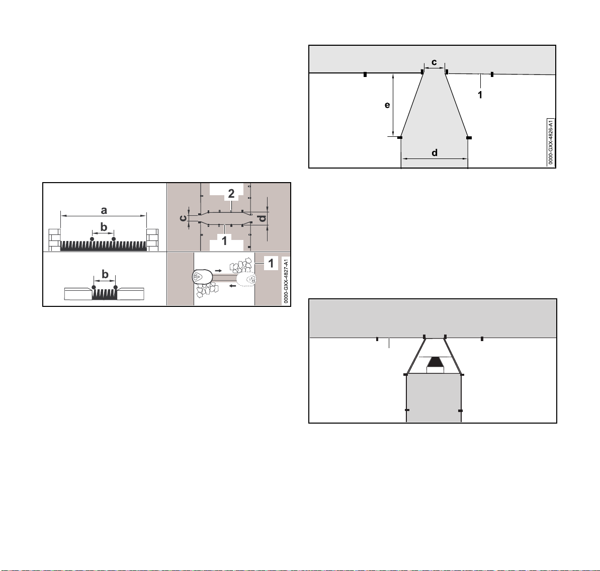
11 Installing the Perimeter Wire
The wire spacing and the STIHL Corridor Pattern are
matched to the installation of the perimeter wire on the lawn
surface. If the perimeter wire is buried very deeply, e.g.
under stone paving, the dimensions differ. Check the
function and adjust the wire installation if necessary.
In corridors, the lawn is only mowed along the path of the
perimeter wire.
To install a corridor:
► Remove stones, pieces of metal, glass, wire or other
objects that could be thrown or flung by the cutting
attachment.
English
► Install a gate, which is a funnel-shaped entrance and exit
area at each end of the corridor. Keep the following
distances:
– c = 3.9 in. (10 cm)
–d=11in. (27cm)
– e = 6.7 in. (17 cm)
The iMow will not enter the corridor unintentionally.
► Install the perimeter wire (1) in a straight line on the left
and right side of the corridor entrance. The straight line
must be at least one length of the robotic mower.
► Keep a minimum clearance between obstacles higher
than 0.4 in. (1 cm) of a = 42.5 in. (108 cm).
► Keep a minimum clearance between obstacles lower than
0.4 in. (1 cm), paths/obstacles that can be travelled on, of
b = 11 in. (27 cm).
► Route the perimeter wire (1) parallel to the ground and
attach it to the ground with a sufficient number of wire
stakes (2).
0478-131-3046-C
1
► Use the tunnel-shaped STIHL Corridor Pattern (C) to
install the gate at each end of the corridor.
► When using the "Passage" feature ("Offset Drive Home"),
search loops must be installed in the linked area in order
for the iMow to be able to locate the gate and return to the
docking station, @ 11.9.
► Define at least 1 starting point in the linked area, @ 15.6.
C
41
0000-GXX-5414-A0
Page 44

English
11 Installing the Perimeter Wire
► If necessary, activate automatic edge mowing or mow the
corridor area manually on a regular basis, @ 14.3 and
@ 15.3.
Corridor Installation Example
4 4
B
2
1
The docking station (1) is installed in the primary mowing
area (A). A linked mowing area (B) is linked to the primary
mowing area with a corridor (2). The perimeter wire (3) can
be followed by the robotic mower. To ensure mowing of the
linked mowing area, two starting points (4) were defined.
A
11.9 Installing Search Loops
To help the robotic mower recognize the location of an
external docking station or a corridor, or if the "Passage"
function ("Offset Drive Home") is activated, search loops
should be installed. If the robotic mower crosses a search
loop during its drive home, the robotic mower will then
directly travel to the perimeter wire and to the docking
station or through the corridor.
3
To install a search loop:
1
a
1
1
C
b
a
d
► Keep a minimum clearance of a = 6.6 ft. (2 m) from the
corners of the mowing area.
► Install the perimeter wire (1) with a minimum length of
0000-GXX-3400-A1
b = 3.3 ft. (1 m) and with a distance of d = 0.4 in. (1 cm) in
between.
► Fasten the perimeter wire to the ground with two wire
stakes at the edge (A). Do not cross the perimeter wires.
Keep them parallel.
► Attach the search loop to the ground with a sufficient
number of wire stakes.
To install a search loop in combination with an external
docking station:
11
A
A
0000-GXX-3406-A1
42
aa
0000-GXX-3404-A0
► Install two search loops (1), each at a 90° angle on the left
and right side of the docking station.
► Keep a minimum clearance of a = 6.6 ft. (2 m) from the
docking station.
0478-131-3046-C
Page 45

11 Installing the Perimeter Wire
1
1
2
1
0000-GXX-3403-A0
English
To install a search loop in combination with a corridor:
11
aa
► Install two search loops (1) at an angle of 90° in the part
of the mowing area that can only be reached via a corridor.
► Keep a minimum clearance of a = 6.6 ft. (2 m) from the
corridor entrance.
11.10 Installing Linking Sections
A linking section links a secondary area to the primary
mowing area, e.g. a mowing area in front of and behind the
house that the iMow cannot travel to on its own. This allows
both mowing areas to be mowed automatically.
11.11 Accurate Mowing Along Edges
0000-GXX-3405-A0
► Along high obstacles, route the perimeter wire with a
minimum clearance of 13 in. (33 cm) from the obstacle.
This buffer area will be left unmowed.
To avoid the buffer area which will be left unmowed, you can
lay edging stones or pavers around high obstacles, e.g.
walls. The width of the eding stones must be at least
b = 10.2 in. (26 cm).
11.12 Sloping Terrain in the Mowing Area
NOTICE
STIHL recommends that you install the perimeter wire at a
maximum pitch of +/- 10 degrees. The perimeter wire can be
installed up to +/- 15 degrees, but this can require additional
adjustments to the perimeter wire installation. Slopes should
also be noted in the garden sketch.
Maintain a minimum distance of at least 39.4 in. (100 cm)
from water and other potential drop-offs, such as edges and
steps.
► Route the perimeter wire (1) parallel and close to one
another.
► Attach the linking section to the ground with a sufficient
number of wire stakes (2).
0478-131-3046-C
43
Page 46

English
11 Installing the Perimeter Wire
To install the perimeter wire at a slope with an incline of 5°
to 15°:
a
1
5-15
► Route the perimeter wire (1) past the top edge of the
slope, keeping a minimum clearance of a = 19.7 in.
(0.5 m).
1
15
► If the incline exceeds 15°, route the perimeter wire so that
the robotic mower will stop before it reaches the edge of
the slope. The top edge of the slope and the slope itself
should remain outside the mowing area.
To install reserve wire:
1
a
0000-GXX-3408-A0
► Route the perimeter wire (1) between 2 wire stakes
spaced approximately a = 3.3 ft. (1 m) apart.
► Attach the reserve wire to the ground in the center using
an additional wire stake.
11.14 Using Wire Connectors
WARNING
To reduce serious or fatal injury or property damage from
fire or electric shock, use only wire connectors authorized by
STIHL.
Wire connectors are designed to link two loose ends of
perimeter wire to extend the perimeter wire or to connect
loose wire ends caused by a breakage. They are filled with
0000-GXX-3409-A1
gel to prevent premature wear or corrosion of the wire ends.
► Note the positions of the wire connectors on your sketch
of the mowing area, @ 11.2.
0000-GXX-3410-A0
11.13 Installing Reserve Wire
Installing reserve lengths of perimeter wire at regular
intervals will make it easier to later modify the mowing area
or placement of the docking station if that should become
necessary.
44
0478-131-3046-C
Page 47

12 Docking Station
a
0000-GXX-3412-A1
1
2
► Insert the unstripped wire ends (2) in the wire
connector (1).
► Press the wire connector together using suitable pliers.
English
In the garden sketch, note those areas where the perimeter
wire is routed closer to the edge of the mowing area.
0000-GXX-3411-A1
► Install the perimeter wire (1) with the aid of the
iMow Ruler (2) as illustrated.
–a=11in. (27cm)
12 Docking Station
12.1 LED on the Docking Station
► Attach the perimeter wire to the ground using two wire
stakes, leaving a = 2 in (5 cm) of strain relief as depicted
above.
11.15 Installing the Perimeter Wire Closer to the Edge of the Mowing Area
Following installation, make sure there is at least a 2 in.
(5 cm) gap between the robotic mower and the obstacle
during operation, @ 10.7, @ 15.3. If necessary, increase
the wire clearance from the obstacle. In straight sections,
the perimeter wire can be routed as close as 11 in. (27 cm)
from high obstacles. This will reduce the amount of
unmowed grass.
0478-131-3046-C
1
0000-GXX-3341-A0
A red LED (1) shows the status of the docking station and
the perimeter wire signal.
If the LED is off: The docking station is switched off and the
wire signal is not being transmitted.
If the LED glows: The docking station is switched on and the
robotic mower is not docked.
45
Page 48

English
12 Docking Station
If the LED flashes slowly: The docking station is switched
on, the robotic mower has docked successfully or is being
charged.
If the LED glows for 3 seconds followed by a 1 second
pause: The "Homecall" function is activated and the robotic
mower has received a command to return to the docking
station.
If the LED flashes rapidly (approximately two times per
second): The perimeter wire is not properly connected to the
docking station or the wire signal is no longer present. The
perimeter wire may be broken (wire break).
If the LED flashes rapidly at intervals: The LED flashes
alternately 3 times at a 1- second interval, 3 times at a 2second interval, 3 times at a 1-second interval, 5 second
pause. After the pause, the signal is repeated. The docking
station has a malfunction. For troubleshooting information,
@ 21.2.
12.2 Docking Station Controls
1
ON/OFF/Home button
Press and hold the ON/OFF/Home button for
2 seconds during a mowing operation to switch off
the wire signal. The robotic mower will stop, remain in
the mowing area and a corresponding message will
appear in the display of the robotic mower.
Press the ON/OFF/Home button twice within
2 seconds during a mowing operation to bring back
the robotic mower to the docking station (Homecall).
The robotic mower will end its current mowing
operation, search for the perimeter wire and return to
the docking station to recharge the battery. When
Homecall is initiated, the robotic mower will not start
any further mowing operations during the current
active time. A Homecall remains active until the
robotic mower is docked. You can end Homecall
manually by pressing the ON/OFF/Home button twice
within 2 seconds. It will resume mowing operations
during its next scheduled active time.
12.3 Docking the Robotic Mower
Automatic docking
The robotic mower will travel to the docking station
automatically and dock when the active time ends or the
robotic mower needs to be recharged.
Docking with the Homecall function
The robotic mower can be called back to the docking station
manually. To call the robotic mower back:
► Press the ON/OFF/Home button on the docking station
twice within 2 seconds.
The robotic mower will return to the docking station and
will not start any further mowing operation during the
current active time.
0000-GXX-3341-A0
Manual docking
► Remove the control panel / manual controller and activate
the Hand control command, @ 16.4 and @ 14.3.
► Steer the robotic mower to the docking station using the
control panel / manual controller or activate the disabling
device and transport the robotic mower to the docking
station by hand, @ 17.1.
46
0478-131-3046-C
Page 49

12 Docking Station
1
► Lift the robotic mower slightly by the carrying handle (1)
and relieve the weight on the drive wheels.
► Push the robotic mower, resting on its front wheels, into
the docking station.
► Insert the control panel / manual controller, @ 16.4.
Manual Charging
To start charging:
► Dock the robotic mower.
► If necessary, end standby mode of the robotic mower by
pressing any button.
Charging will start automatically.
During charging, the status screen will show the
charging symbol and the message "Charging
battery".
0000-GXX-3390-A1
In all the other menus, the display will show a plug
symbol to indicate that the robotic mower is charging.
Charging time depends on a number of factors, including
battery condition and the ambient temperature. Exposure to
direct sunlight can lead to increased temperatures inside the
machine and battery compartment, which can increase
battery charging times.
English
12.4 Charging the Robotic Mower
WARNING
Read and follow the safety precautions and instructions for
the robotic mower and docking station in this manual, @ 5.4
and @ 6. Be alert for signs that the integrated battery may
be damaged. To reduce the risk of personal injury from short
circuit, fire and explosion, never use or charge a robotic
mower if the hood or housing is cracked, deformed or
excessively hot, if battery fluid is leaking from the battery
compartment, or if the battery is otherwise damaged,
@ 5.5.
WARNING
To reduce the risk of electric shock, charge the robotic
mower only in the docking station. Do no remove the battery
or attempt to charge it using an external power supply.
Automatic charging
The robotic mower will begin charging automatically when it
returns to the docking station at the end of the mowing
operation and its energy level is below a certain value.
0478-131-3046-C
Charge status
The status screen will show the current state of
charge.
In all the other menus, the display will show a battery
symbol to indicate the robotic mower's charge status.
0000-GXX-3878-A0
If you end standby mode, but the state of charge is too low
for the robotic mower to return to the docking station, this
symbol is displayed over the entire screen. After a few
seconds, the display will turn off and the robotic mower will
return to standby mode.
47
Page 50

English
13 Control Panel / Manual Controller Display Information
13 Control Panel / Manual Controller
Display Information
13.1 Information Area
The following information is shown in the top right corner of
the display:
1. Time
The current time is indicated in 24-hour format.
2. Automatic mowing status
When automatic mowing is switched on, the
Automatic symbol appears.
► Configure the status screen with various information,
@ 15.2.
Status screen when the robotic mower is not in operation
0000-GXX-5340-A0
The text "iMow ready for op." and the automatic mowing
status is displayed in the bottom area of the screen.
There are two configurable fields in the top display area.
Status screen during operation
0000-GXX-3377-A00000-GXX-3379-A0
3. Charge status
The battery symbol shows the battery's state of charge. For
example:
– No bars: battery discharged
– 1 to 5 bars: battery partially discharged
– 6 bars: full charge.
During charging, the plug symbol is displayed instead
of the battery symbol.
13.2 Status Screens
Different status screens may appear, depending on the
status of the robotic mower.
48
The text "Attention – iMow starting" and the safety alert
symbol are displayed before a mowing operation starts.
Flashing of the display illumination and a signal tone
additionally indicate the start of the mower.
0478-131-3046-C
Page 51

14 Menu Functions
0000-GXX-3378-A0
The text "iMow mowing lawn" and a corresponding symbol
are displayed during an active mowing operation. The text
and symbol will depend on the specific active operation.
Edge mowing: While the robotic mower mows the
edges of the mowing area, the text "Mowing edge" is
displayed.
Drive to docking station: When the robotic mower
returns to the docking station, the relevant reason is
indicated in the display (e.g., "Battery discharged" or
"Mowing completed").
Battery charging: The text "Charging battery"
appears during charging.
Status screen for messages
If an error occurs during operation, a message will be
displayed that includes the date and time of its occurrence
and the relevant message code. If several messages apply,
they appear alternatively, @ 21.1.
14 Menu Functions
14.1 Navigating the Menus
► Select a submenu using the navigation pad.
If a submenu is selected, it is displayed on a black
background.
► Open the selected submenu by pressing the OK button.
In the second menu level, the various submenus are
shown as tabs.
► Select a tab by pressing the navigation pad to the left or
right.
► Select a submenu by pressing the navigation pad
downwards or upwards.
Selected tabs and submenu entries are displayed on a
black background.
► If there is a scroll bar at the right edge of the display, see
further entries by pressing the navigation pad downwards
or upwards.
► Press the OK button to open a submenu.
0000-GXX-3380-A0
English
0000-GXX-3375-A0
0478-131-3046-C
49
Page 52

English
0000-GXX-3376-A0
14 Menu Functions
Dialog window
Options are listed in the submenus. Selected entries are
displayed on a black background.
► Press the OK button to open a selection window or dialog
window.
Selection window
2019
2018
2017
The selected value is displayed on a black background.
► Navigate through the values and change them by using
the navigation pad.
► Press the OK button to confirm your selections.
0000-GXX-3595-A0
If changes have to be saved or messages confirmed, a
dialog window appears in the display. The selected button is
displayed on a black background.
► Press the OK button to confirm the selection.
14.2 Overview
The main menu contains 4 submenus. The main
menu will be displayed,
– when the status screen (@ 13.2) is quit by
pressing the OK button,
– when the "Main menu" command is activated,
– when the Back button is pressed in the second
menu level.
50
0478-131-3046-C
Page 53

14 Menu Functions
0000-GXX-3383-A0
English
Commands
This submenu contains a set of autonomous mowing
operations, @ 14.3.
Information
This submenu contains information about the lawn or
the robotic mower's status, @ 14.4.
Mowing plan
This submenu contains functions to change the
mowing plan, @ 14.5.
Settings
This submenu contains functions to change the
robotic mower's settings, @ 15.2.
14.3 Commands
Lock robotic mower and activate disabling device
Select to return to lock the robotic mower and activate
the disabling device.
Switch automatic mowing on/off
Select to turn automatic mowing on or off.
When automatic mowing is switched on, the text
"Automatic switched on" appears in the status screen
and the symbol is displayed next to the battery
symbol.
When automatic mowing is switched off, the text
"Automatic switched off" appears in the status screen
and the active times are shown as inactive (greyed
out) in the mowing plan.
Drive to docking station
Select to command the robotic mower to drive to the
docking station immediately.
The robotic mower travels back to the docking station
and charges its battery. If automatic mowing is
switched on, the robotic mower will start to mow the
mowing area again at the next possible active time.
Hand control
Select to activate manual lawn mowing.
Use the navigation pad to steer the robotic mower,
@ 16.5.
► Select a tab by pressing the navigation pad to the left or
right.
► Press the OK button to open the submenu.
Main menu
Select to return to the main menu.
0478-131-3046-C
51
Page 54

English
14 Menu Functions
Start mowing
Select to start the mowing operation immediately.
If a secondary area was installed, press the OK
button and then specify whether the mowing
operation is taking place in a secondary area or in the
main area, @ 16.7.
If an external docking station with a corridor was
installed, bring the robotic mower to the mowing area
before activation of the command "Start mowing."
You will be prompted to enter the time to end the
mowing operation. The default setting for the duration
of the mowing operation can be modified under
"Mowing time" in the machine settings, @ 15.
Mowing time in primary or linked areas following the
"Start mowing" command will be deducted from the
weekly mowing plan's total mowing duration.
Start time-delayed mowing
Select to set a defined time to start the mowing
operation.
If a secondary area was installed, after pressing the
OK button it is necessary to define whether the
mowing operation is taking place on a secondary
area or on the main area, @ 16.7.
If an external docking station with a corridor was
installed, bring the robotic mower to the mowing area
before activation of the command "Start time-delayed
mowing".
You will be prompted to enter the time to end the
mowing operation. The default setting for the duration
of the mowing operation can be modified under
"Mowing time" in the machine settings, @ 15.
Mowing time in primary or linked areas following the
"Start time-delayed mowing" command will be
deducted from the weekly mowing plan's total
mowing duration.
Skip next active time
Select to skip the next active time.
No mowing will take place during the next active time.
Active times which have been cancelled in this
manner are greyed out in the mowing plan. They can
be released for mowing again in the "Daily plan"
menu, @ 14.6.
If the command is performed several times in
succession, the next active time is always skipped. If
no active times remain for the current week, the
message "No mowing will take place next week"
appears.
Edge mowing
Press the OK button to mow the edge of the mowing
area.
After completing one circuit, the robotic mower
travels back to the docking station and charges the
battery.
14.4 Information
0000-GXX-3388-A0
52
0478-131-3046-C
Page 55

14 Menu Functions
English
Messages
This submenu contains a list of all active errors, faults
and recommendations including date and time of
their occurrence and the respective message code.
Press the OK button to display details for every
message, @ 21.1.
If no messages are available, this display shows the
text "No messages."
Events
This submenu contains a list of the last activities of
the robotic mower. Details of the events (additional
text, time and code) can be displayed by pressing the
OK button.
Errors during normal operation are documented in
the messages.
Robotic mower status
This submenu contains information on the robotic
mower's status:
– Charging status: Battery charging status in percent
– Rem. time: The remaining mowing duration during
the current week in hours and minutes
– Time and date
– Start time: Start of the next planned mowing
operation
– Total number of completed mowing operations
– Mowing hours: Duration of all completed mowing
operations in hours
– Distance: Total distance covered in meters
– Ser.-No.: Serial number of the robotic mower. This
is also to be found on the identification plate in the
compartment beneath the control panel / manual
controller.
– Battery: Serial number of the battery
– Software: Installed machine software
Lawn information
This submenu contains information on the lawn:
– Mowing area in square meters: This measurement
is taken during installation
– Round time: Duration of one circuit around the
mowing area in minutes and seconds
– Starting points 1 – 4: Distance of the relevant
starting point from the docking station in meters,
measured in a clockwise direction
– Circumference: Circumference of the mowing area
in meters
– Edge mowing: Frequency of edge mowing per
week
14.5 Mowing Plan
Mowing Plan Theory of Operation
Before changing your mowing plan, read the following
section carefully.
During the initial setup, the iMow will automatically calculate
an appropriate automatic mowing plan. That plan consists of
active times and a weekly mowing duration. Active times are
those windows of time in which the iMow is programmed to
mow automatically. The iMow will only mow in automatic
mode during the active times. The mowing duration is the
total number of hours the iMow will mow per week.
Satisfactory cutting results depend on the iMow having
sufficient mowing duration and sufficient active times to
complete the mowing operation for the entire lawn.
Automatic mowing will cease once the iMow has reached its
total allotted mowing duration for the week, even if there are
remaining active times scheduled.
The active times and mowing duration must be set properly
to ensure that a sufficient number of mowing hours are set
each week (mowing duration) and that the iMow has
sufficient windows of time (active times) to complete the
mowing.
0478-131-3046-C
53
Page 56

English
14 Menu Functions
If you increase the mowing duration, be sure expand the
active times as well to accommodate the increased number
of mowing hours. The total weekly active time must be
higher than the total weekly mowing duration in order to
account for charging time and to provide a buffer in case
active times are missed due to rainfall.
The status screen displays the remaining mowing duration
for the week and the next scheduled active time.
Mowing Plan Menu
Call up the stored mowing plan in the "Mowing plan"
submenu.
The rectangular blocks displayed in black beneath the days
of the week represent the saved active times. When
automatic mowing is turned on, mowing operations take
place only during active times. The iMow will not mow during
all active times as the iMow may return to the docking station
if it starts raining or the iMow requires charging.
Blocks displayed in grey represent active times without
mowing operations, e.g. where the active time has been
deactivated by the operator or the active time has been
skipped, @ 14.3. When automatic mowing is turned off, the
entire mowing plan is deactivated and all active times are
shown in grey.
► Select an active time or the mowing duration by pressing
the navigation pad downwards or upwards.
► Open the settings by pressing the OK button.
If you want to edit the active times for an individual
day, press the navigation pad to the left or right to
select the day.
Select the "Active times" submenu and press the OK
button.
14.6 Active Times
WARNING
Keep bystanders, especially children, and pets out of the
mowing area during active times. Never allow children to
approach or play with the robotic mower. Keep children and
pets away from the mower while it is in operation. Never
allow the robotic mower to operate if you know that animals
or persons are or may be in the mowing area or vicinity.
Next to every active time, a symbol shows the current status
of the active time:
This symbol indicates that the active time is
activated. The robotic mower will mow automatically
according to the mowing plan.
This symbol indicates that the active time is
deactivated. The robotic mower will not mow during
this time.
54
0478-131-3046-C
Page 57

14 Menu Functions
0000-GXX-3386-A0
English
If active times are not sufficient to allow for the necessary
mowing and charging operations, you can increase active
times or reduce the mowing duration. To edit the active
times:
Select the "New active time" menu item to add an
active time. An additional active time may not overlap
with other active times.
Up to 3 active times per day can be saved.
Select "Delete all active times" to delete all active
times on the selected day.
The robotic mower will no longer operate on this day.
Select "Active time on/off" to enable or disable the
selected time for automatic mowing.
Select "Change active time" to change the time the
robotic mower will be mowing.
Select "Delete active time" to delete this specific
active time.
The robotic mower will no longer operate at this time.
NOTICE
If you have a sprinkler system, program the robotic mower
to avoid active watering times to reduce the likelihood of
damage to the sprinkler heads from contact with the mowing
blade. The mower and sprinkler system should never be run
at the same time.
14.7 Mowing Duration
Select "Change mowing duration" to change the total
weekly mowing hours. The mowing duration set
during initial installation is based on the size of the
mowing area, but it can be increased or decreased in
this submenu.
Select "New mowing plan" to delete all currently
stored active times and to program a new mowing
plan. The step "Program the robotic mower" of the
installation assistant will be called up, @ 10.8.
If you are reprogramming the mowing plan during one of the
in your new mowing plan, active times, the robotic mower
will begin an automatic mowing operation after you confirm
the new mowing plan.
0478-131-3046-C
55
Page 58

English
15 Settings
15 Settings
15.1 Settings Overview
The Settings menu contains 5 submenus, displayed as
buttons:
Robotic mower
Select this submenu to change the robotic mower's
settings, @ 15.2.
Installation
Select this submenu to change and test the
installation, @ 15.3.
Safety
Select this submenu to change the security settings,
@ 15.4.
Service
Select this submenu to confirm replacement of the
mowing blade. This will reset the internal blade
replacement counter. Also select this submenu to find
a wire break, @ 15.5.
Dealer area
This code-protected submenu is accessible only by
your authorized STIHL iMow servicing dealer.
15.2 iMow Settings
Rain Sensor
Adjust the sensitivity of the 5-stage rain sensor.
To set the rain sensor:
► Press the navigation pad to the left or right. The current
value is displayed by means of a line diagram.
Select this option to allow mowing at higher moisture
levels. If the bar is moved all the way to the left, the
robotic mower will mow even when it is raining.
Select this option to allow mowing under ordinary
ambient conditions.
Select this option to allow mowing only at lower
moisture levels. If the bar is moved all the way to the
right, the robotic mower will only mow if the rain
sensor is completely dry.
Mowing Time
Set the default mowing time for the duration of a
mowing operation when activating automatic mowing
with the "Start mowing" command, @ 14.3.
Delay
Set the length of the delay when activating the "Start
time-delayed mowing" command, @ 14.3.
Status Screen
You can edit the status screen to display the
information you want to appear, @ 13.2.
To set the status screen:
► Select the left or right part of the screen using the
navigation pad and confirm your selection by pressing OK.
► For each part of the display, select one of the following to
appear on the status screen:
Charging status: The battery charging status in
percent will appear on the status screen.
Rem. time: The remaining mowing duration during
the current week will appear on the status screen.
Time and date: The current date and current time will
appear on the status screen.
Start time: The start of the next planned mowing
operation will appear on the status screen. During a
running active time, the text "active" will be displayed.
56
0478-131-3046-C
Page 59

15 Settings
English
Mowing events: The total number of mowing
operations performed will appear on the status
screen.
Mowing hours: The total duration of all mowing
operations performed will appear on the status
screen.
Distance: The total distance traveled will appear on
the status screen.
Time
Set the current time.
Always set the correct time to ensure an accurate
mowing plan and to prevent automatic mowing at
unwanted times.
Date
Set the current calender date.
Always set the correct date to ensure an accurate
mowing plan and to prevent automatic mowing at
unwanted times.
Date Format
Set your desired date format.
Track offset
Change the robotic mower's standard 2.36 in. (6 cm)
offset from the perimeter wire to a smaller or larger
offset (1.18 in. to 3.54 in. (3 cm to 9 cm)).
To ensure optimal performance under the standard
setup instructions, STIHL recommends that you keep
the default track offset setting.
Language
Set the desired display language. The language
selected during initial installation is set as the default.
Contrast
Change the display's contrast.
15.3 Installation
Passage (Offset Drive Home)
The robotic mower can travel back to the docking station
with an increased offset to the perimeter wire.
► Ensure that the perimeter wire has been routed with a
clearance of at least 2 m at the narrowest sections.
► Activate the passage setting to change the way the robotic
mower travels back home to the docking station. Select
one of three options:
– Off (default setting): The robotic mower travels along
the perimeter wire.
– Narrow: The robotic mower travels along the perimeter
wire or with an offset of 15.7 in. (40 cm) inside the
perimeter wire.
– Wide: The robotic mower travels within a passage of
15.7 in. to 31.5 in. (40 cm to 80 cm) from the perimeter
wire.
► If you have installed an external docking station, a
confined area or a linked section using a corridor, install
search loops for offset drive home, @ 11.9.
ASM (Anti-Stuck-Maneuver)
The robotic mower starts an evasive routine if it becomes
stuck: ASM is switched off by default.
► Leave the default setting (ASM switched off), if there are
large, flat expanses in the mowing area (e.g. asphalt
driveways), if the robotic mower often unexpectedly turns
90° during operation or if the mower unexpectedly stops
mowing and the display shows the message "1131 Stuck".
New installation
The current mowing plan will be deleted and the
installation assistant will start again.
0478-131-3046-C
57
Page 60

English
15 Settings
Starting points
To set starting points, see @ 15.6.
Test edge
Start a test run for checking correct wire routing. The
step "Check installation" of the installation assistant
will be called up, @ 10.7.
► To check correct wire routing around restricted areas,
position the robotic mower in the mowing area with the
front facing the restricted area and start the test run.
Edge mowing
Select the mowing frequency for edges.
► Select one of three options:
– Never: The edges will never be mowed.
– Once (default): The edges will be mowed once a week.
– Twice: The edges will be mowed twice a week.
Secondary areas
Enable or disable secondary areas.
► Activate to enable mowing of a secondary area.
15.4 Safety
Disab. device
To activate the disabling device in the "Settings"
menu, open the "Safety" submenu, select "Lock
iMow" and confirm by pressing the OK button.
To deactivate the disabling device, press the Mow
button and the OK button in the sequence illustrated
on the display. Once the disabling device is
deactivated, the robotic mower can be operated
again.
Level
Four security levels can be set. Various locks and
security devices are activated, depending on the
level.
► Select one of four options:
1)None: All functions of the robotic mower can be
accessed.
2)Low:
– Anti-theft alarm: If the mower is lifted or tilted for
longer than 10 seconds, the PIN query appears. If you
do not enter then PIN code within one minute, an
alarm sounds and automatic operation is switched off.
– Connection lock: The PIN code must be entered prior
to linking of the robotic mower and docking station.
– Reset lock: The PIN code must be entered prior to
resetting the machine to the factory defaults.
3)Medium:
– All of the features from the "Low" setting.
– Time lock: PIN code query for changing a setting if no
PIN code has been entered for more than one month.
4)High:
– All of the features from the "Medium" setting.
– Setting protection: The PIN code must be entered
before settings can be changed.
► Select the desired security level and confirm it by pressing
the OK button.
► If necessary, enter the 4-digit PIN code.
STIHL recommends that the "Low", "Medium" or "High"
security level be set.
Change PIN code
The 4-digit PIN code can be changed if necessary.
The "Change PIN code" menu item is only displayed
in the "Low," "Medium" or "High" settings.
► Enter the old PIN code and confirm it by pressing the OK
button.
► Enter the new 4-digit PIN code and confirm it by pressing
the OK button.
58
0478-131-3046-C
Page 61

15 Settings
Take note of your PIN code and keep it in a safe place. If the
PIN code is entered incorrectly 5 times, automatic operation
is switched off and can only be restored with a master code
generated by your authorized STIHL iMow servicing dealer.
Start signal
The acoustic signal when the mowing blade is
activated.
English
Alarm signal
The acoustic signal when the robotic mower hits an
obstacle.
Menu signal
The acoustic indicator when you open a menu and
confirm a selection by pressing the OK button.
Child lock
If the impact sensor is triggered several times in succession
within a short time, the robotic mower and the mowing blade
will stop.
If the impact sensor is not triggered again, the robotic mower
will continue automatic mowing after a few seconds.
Keylock
When the keylock is activated, the control panel is
locked. The operator must press and hold the Back
button and then press the forward navigation button
on the navigation pad to unlock the control panel /
manual controller. The keylock will lock the control
panel again 2 minutes after the last button is pressed.
Link iMow and dock:
The mower and docking station must be linked if you
replace the docking station the robotic mower.
► Install the docking station and connect the perimeter wire,
@ 10.3 and @ 10.5.
1
0000-GXX-3390-A1
► Lift the robotic mower slightly by the carrying handle (1)
and relieve the weight on the drive wheels. Push the
machine, resting on its front wheels, into the docking
station.
► After pressing the OK button, enter the PIN code.
The robotic mower will then search for the wire signal and
automatically save it for automatic operation. This process
may take several minutes, @ 10.6.
15.5 Service
Blade change
► After mounting a new mowing blade, confirm the
replacement of the mowing blade by pressing the OK
button.
Find wire break
► Activate the assistant to find a wire break by pressing the
OK button.
► Find the wire break, @ 21.3.
Reset settings
► Press the OK button and enter the PIN code.
The robotic mower will be reset to factory defaults and the
installation assistant will be started, @ 10.
0478-131-3046-C
59
Page 62

English
16 During Operation
15.6 Setting Starting Points
► Set starting points to target automatic mowing in a specific
part of your lawn. Starting points are used to access parts
of your lawn that are not being mowed frequently enough,
sometimes because part of the mowing area is accessible
only through a corridor.
Starting points can be set in two different ways.
"Teaching-in" starting points
Press the OK button. The robotic mower will begin to
travel along the perimeter wire. If it is not docked, it
first travels to the docking station. All current existing
starting points are deleted.
To teach-in up to 4 starting points:
► Save each starting point by pressing the OK button during
the robotic mower's travel around the perimeter wire.
► The teach-in procedure is interrupted automatically when
the robotic mower contacts obstacles along the perimeter
wire. If the teach-in procedure is interrupted, remove any
obstacles that may be found along the cutting path or
correct the installation of the perimeter wire.
► If necessary, interrupt the teach-in procedure manually by
pressing the STOP button.
► Check the position of the robotic mower before continuing
the teach-in procedure. The robotic mower must be
located on the perimeter wire or within the mowing area
facing the perimeter wire.
► The starting frequency defines how often a mowing
operation is to begin from a starting point. The default
setting is 2 of 10 mowing operations (2/10) at each starting
point. You can change the starting frequency as desired
after each teach-in.
► If the teach-in procedure has been ended prematurely,
send the robotic mower back the to docking station.
Setting starting points 1 to 4 manually:
Press the OK button. All existing starting points are
deleted.
To manually set up to 4 starting points:
► Determine the distance of the starting points from the
docking station, measured in a clockwise direction.
► Set a starting frequency between 0 of 10 mowing
operations (0/10) and 10 of 10 mowing operations (10/10).
The docking station is defined as starting point 0. Mowing
operations will start from the docking station as a default.
16 During Operation
16.1 Automatic Mowing
WARNING
Keep bystanders, especially children, and pets out of the
mowing area during active times. Never allow children to
approach or play with the robotic mower. Keep children and
pets away from the mower while it is in operation. Never
allow the robotic mower to operate if you know that animals
or persons are or may be in the mowing area or vicinity.
When automatic mowing is switched on, the robotic mower
independently leaves the docking station and mows the lawn
during the active times set by the operator, @ 14.6. The
number and duration of the mowing and charging operations
within the active times are determined automatically.
The mowing plan is determined based on the size of the
mowing area, which is calculated during installation or
during the creation of a new mowing plan.
60
0478-131-3046-C
Page 63

16 During Operation
English
When you switch on automatic mowing, the display
shows the automatic mowing symbol next to the
battery symbol.
► Define starting points within linked areas to ensure that
linked areas will be mowed regularly.
► To end an active mowing operation manually, press the
STOP button on the robotic mower or press the
ON/OFF/Home button on the docking station twice at any
time.
When the battery is discharged, the robotic mower
automatically returns to the docking station.
16.2 Mowing Duration
The mowing duration specifies how many hours per week
the robotic mower will mow the lawn. Charging time is not
included in the mowing duration.
During initial installation, the robotic mower automatically
calculates the mowing duration appropriate for your lawn
based on the size of the mowing area.
To complete a mowing area of approximately 1076 sq. ft.
(100 m²), the robotic mower will need approximately 60
minutes on average.
► If necessary, extend or reduce the active times and
mowing duration, @ 14.6 and @ 14.7.
16.3 Adjusting the Cutting Height
WARNING
To reduce the risk of serious personal injury or death,
always press and hold the STOP button for 5 seconds to
activate the disabling device before adjusting the cutting
height of the mowing blade.
AB
1 1
To lower the cutting height (A):
► Press and turn the rotary knob (1) counterclockwise.
The marking (2) indicates the selected cutting height.
To raise the cutting height (B):
► Press and turn the rotary knob (1) clockwise.
The marking (2) indicates the selected cutting height.
8 different cutting heights can be selected:
– Level 1: 0.79 in. (20 mm)
– Level 2: 1.01 in. (25.7 mm)
– Level 3: 1.24 in. (31.4 mm)
– Level 4: 1.46 in. (37.1 mm)
– Level 5: 1.69 in. (42.8 mm)
– Level 6: 1.91 in. (48.5 mm)
– Level 7: 2.13 in. (54.2 mm)
– Level 8: 2.4 in. (60 mm)
NOTICE
To avoid damaging the perimeter wire, set the cutting height
to level 5 or higher for the first few weeks. This will allow the
grass to grow through and cover the perimeter wire. Levels
1, 2, 3 and 4 are special heights suitable only for flat lawns
with a ground unevenness less than +/- 0.4 in. (1 cm).
2 2
0000-GXX-3342-A0
0478-131-3046-C
61
Page 64

English
16 During Operation
NOTICE
To reduce the risk of damaging the robotic mower, never
attempt to lift, carry or transport the robotic mower by the
rotary knob. The rotary knob is designed to come off the
robotic mower if pulled. This prevents the unit from being
lifted and carried by the rotary knob.
NOTICE
To avoid overloading the motor, avoid setting the cutting
height too low in tall grass. If the motor slows or bogs down
when entering the grass, activate the disabling device and
raise the cutting height.
16.4 Removing and Mounting the Control Panel / Manual Controller
WARNING
To help reduce the risk of serious personal injury or death
from unintentional starting, always press and hold the STOP
button for 5 seconds to activate the disabling device before
approaching the unit while it is operation.
The control panel / manual controller can be removed from
the robotic mower to manually mow or to change the
programming of the robotic mower.
Automatic operation of the robotic mower is only possible
when the control panel / manual controller is mounted
securely onboard the robotic mower.
To remove the control panel / manual controller:
► Press and hold the STOP button for 5 seconds.
1
0000-GXX-5342-A0
► Lift the rear of the control panel / manual controller (1) and
remove it from the robotic mower.
The control panel / manual controller remains connected
to the robotic mower via a spiral cable.
To mount the control panel / manual controller:
► Press and hold the STOP button for 5 seconds.
3
2
62
2
0000-GXX-5341-A0
► Stow the spiral cable in the housing compartment.
► Tilt the control panel / manual controller back slightly and
insert the tabs (2) into the recesses in the housing (3).
► Carefully press down on the front of the control panel /
manual controller until the unit is securely attached and
you hear an audible click.
0478-131-3046-C
Page 65

16 During Operation
English
16.5 Manual Mowing
WARNING
Always keep the robotic mower in front of you during manual
operation and maintain a sufficient distance from the mower
at all times to reduce the risk of personal injury from thrown
objects or blade contact with your feet or other parts of your
body.
WARNING
The impact sensor and edge detection features are disabled
during manual mowing. To reduce the risk of injury, keep
bystanders, especially children, and pets or other animals
out of the mowing area. Avoid directing the mower into
obstacles or over objects that may be thrown or flung by the
mowing blade.
To mow manually:
► Charge the battery if necessary, @ 12.4.
► Remove the control panel / manual controller, @ 16.4.
► Activate the "Hand control" command, @ 14.3.
1
2
► Move and steer the robotic mower (2) using the navigation
pad on control panel / manual controller (1). Two forward
speeds are available:
– Slow: Press the navigation pad lightly
– Fast: Press the navigation pad firmly
To activate the mowing blade, press and hold the OK
button with your right thumb, then press the Mow
button with your left thumb. The mowing blade will
start to rotate and will continue rotating as long as the
Mow button is pressed.
► During manual mowing, keep the Mow button pressed
down with your left hand and operate the navigation pad
with your right hand.
► To deactivate the mowing blade, release the Mow button.
► Return the robotic mower to the docking station for
charging after manual mowing, @ 12.4.
16.6 Adjusting the Mowing Duration and Active
Times
During active times, the robotic mower leaves the docking
station and mows the lawn autonomously. During these
times, mowing operations, charging operations and rest
periods take place. The robotic mower automatically
distributes the mowing and charging operations between the
available time windows. Under certain circumstances (e.g.
when grass growth is slowed by weather conditions), not all
the active times may be necessary for optimal lawn care.
The active times and the mowing duration can be changed
manually. You can set up to 3 different active times per day,
@ 14.5.
► You may wish to change the mowing duration and active
times for one of the following reasons:
– Additional active times for further mowing operations
0000-GXX-3593-A1
are necessary to complete the weekly mowing duration.
– The active times need to be modified to prevent mowing
during a particular time of day.
– Individual active times need to be omitted, because the
mowing area will be in use, e.g., for a backyard party.
► You may wish to extend the mowing duration and active
times for one of the following reasons:
– There are areas which are not mowed sufficiently.
– Intensive grass growth.
– Particularly dense lawn.
0478-131-3046-C
63
Page 66

English
1
0000-GXX-3605-A1
17 Transporting
► You may wish to reduce the mowing duration and active
times when there is slower grass growth due to heat, cold
or dryness.
► You must re-link the docking station and create a new
mowing plan if the size of the mowing area has been
changed or the docking station has been relocated.
16.7 Mowing Outside of Active Times
Mowing primary mowing areas
► In order to mow a part of the mowing area that can only be
reached via a corridor, carry or steer the robotic mower to
the linked area.
► For immediate mowing, call up the "Start mowing"
command or press the Mow button, @ 14.3.
The mowing operation starts immediately and continues
until the selected time.
► For time-delayed mowing, call up the command "Start
time-delayed mowing", @ 14.3.
The mowing operation starts at the selected start time and
continues until the selected end time.
► To end an active mowing operation manually, press the
STOP button on the robotic mower. To return the robotic
mower to the docking station, press the ON/OFF/Home
button on the docking station twice at any time.
Secondary areas
► Carry or steer the robotic mower to the secondary area.
► Activate the secondary area, @ 15.3.
► For immediate mowing, call up the "Start mowing"
command or press the Mow button, @ 14.3.
The mowing operation starts immediately and continues
until the selected time.
► For time-delayed mowing, call up the command "Start
time-delayed mowing", @ 14.3.
The mowing operation starts at the selected start time and
continues until the selected end time.
When the selected end time is reached, the robotic mower
travels to the perimeter wire and comes to a standstill.
► Return the machine to the docking station to recharge the
battery and confirm the displayed message, @ 21.1.
► To end an active mowing operation manually, press the
STOP button on the robotic mower.
If the battery is discharged before the selected end time, the
mowing operation will be shortened accordingly.
17 Transporting
17.1 Transporting the Robotic Mower
When transporting the robotic mower:
► Always disable the robotic mower by pressing and holding
the STOP button for 5 seconds before lifting or
transporting.
► When carrying the robotic mower by hand, hold it by the
carrying handing (1) with the mowing blade pointing away
from you. Never attempt to carry the robotic mower by its
hood.
► When transporting the robotic mower in a vehicle, position
robotic and secure the mower to prevent turnover, impact
and damage. Fasten the machine using suitable fastening
materials (straps, ropes) (see illustration above).
► Secure any other components being transported (e.g.
docking station, small components) to prevent turnover,
impact and damage.
64
0478-131-3046-C
Page 67

18 Storing the Robotic Mower and Docking Station
English
A Note on Battery Transport
The battery inside this robotic mower complies with the
requirements set forth in UN-Manual
ST/SG/AC.10/11/Rev.5/Part III, Subsection 38.3.
Commercial air, vessel and ground transportation of lithium
ion cells and batteries contained in equipment is regulated.
The battery inside this robotic mower is classified as a UN
3481, Class 9, packaging group II product. Shipping it
requires compliance with all applicable shipping regulations.
Check with the ground, vessel, air cargo or passenger airline
to determine if transport is prohibited or subject to
restrictions or exemptions prior to shipping or travel.
Normally, no further conditions have to be met by the user in
order to transport this robotic mower by road to the operating
site. Check and comply with any special regulations that
may apply to your situation.
For further information please go to
www.stihlusa.com/battery-transportation-safety.
18 Storing the Robotic Mower and
Docking Station
18.1 Robotic Mower
WARNING
After the mowing season is over, or any time the robotic
mower is not available for mowing operations, store the
iMow indoors in a dry, secure place that is inaccessible to
children and other unauthorized users, @ 5.4. Improper
storage can result in unauthorized use and damage to the
robotic mower, @ 5.4. Never place or store objects on the
robotic mower.
WARNING
If the robotic mower is damp or wet, dry it thoroughly before
storing to reduce the risk of short circuit and electric shock,
@ 5.4.
WARNING
High temperatures may cause the integrated battery to
generate heat, rupture, leak, ignite or explode, resulting in
severe or fatal personal injury or property damage, @ 5.5.
Store the robotic mower only within an ambient temperature
range of 32 °F to 122 °F (0 °C to 50 °C), @ 5.5. Never
store the robotic mower inside a vehicle in hot weather,
@ 5.5.
When storing the robotic mower for three months or longer
(e.g. winter break):
► Charge the battery fully, @ 12.4.
► Switch off automatic mowing, @ 14.3.
► Set the highest security level, @ 15.4.
► Activate the disabling device, @ 9.1.
► Clean the robotic mower, @ 19.
► Dock the robotic mower in the docking station.
► Store the robotic mower and docking station indoors in a
dry and secure location, out of the reach of children and
other unauthorized persons.
► At the end of the mowing season, protect the terminals
(connectors) removed from the docking station from
environmental damage by wrapping them with a generous
amount of insulating tape or storing them in a container
with grease so that they are protected from the elements.
NOTICE
Charging the battery fully before storage will help prevent
damage and prolong its useful life.
NOTICE
Avoid contacting the perimeter wire when de-thatching or
aerating the lawn. Also use caution when operating a line
trimmer near the perimeter wire. De-thatching, aerating and
trimming operations can result in a cut or damaged
perimeter wire. Refer to your sketch of the mowing area and
take special care to avoid the perimeter wire when
performing these operations.
0478-131-3046-C
65
Page 68

English
19 Cleaning
18.2 Docking Station and Power Supply
WARNING
Store the docking station and the power supply indoors in a
dry, secure place that is inaccessible to children and other
unauthorized users, @ 6. Improper storage can result in
unauthorized use and damage to the docking station or the
power supply, @ 6. Never place or store objects on the
docking station.
WARNING
To reduce the risk of electric shock, always unplug the
power supply from the electrical socket before removing the
cover of the docking station.
When storing the docking station or the power supply for
three months or longer (e.g. winter break):
► Disconnect the power supply from the electrical outlet.
► Remove the docking station cover.
► Open the panel.
1
2
3
4
► Do not remove the perimeter wire from the mowing area.
► Disconnect the power supply from the docking station.
► Close the panel.
► Reinstall the docking station cover.
► Remove the docking station.
► At the end of the mowing season, protect the loose
perimeter ends removed from the docking station by
wrapping a generous amount of insulating tape or storing
them in a container with grease so that they are protected
from the elements.
► Store the docking station and the power supply indoors in
a dry and secure location, out of the reach of children and
other unauthorized persons.
19 Cleaning
19.1 Cleaning the Robotic Mower and Docking
Station
WARNING
To reduce the risk of personal injury from unintended
activation, activate the disabling device. Disconnect the
power supply from the electrical outlet before carrying out
any cleaning work, @ 7. Users of this robotic mower should
carry out only the cleaning described in this manual. To help
prevent injuries, always wear heavy-duty work gloves when
handling the mowing blade.
► Press and open the left clamping lever (2).
► Pull out the stripped perimeter wire end (1).
► Close the clamping lever.
► Press and open the right clamping lever (4).
► Pull out the stripped perimeter wire end (3).
► Close the clamping lever.
► Open the cover of the cable duct and guide the perimeter
wire out of the docking station socket.
66
0000-GXX-5415-A1
0478-131-3046-C
Page 69

20 Inspection and Maintenance
English
To clean the robotic mower and the docking station:
► Place the robotic mower on a firm, level and flat surface
for cleaning the upper side of the robotic mower.
► To clean the underside of the machine (mowing blade,
mowing deck), tilt the robotic mower onto its left side and
lean it against a wall (see illustration above).
► Remove accumulated clipping deposits in the housing and
in the mowing deck.
► Clean off dirt with a brush or a cloth. Do not use
detergents or harsh solvents, which may damage or
weaken polymer components.
► Clean the docking station with a brush, a slightly
dampened cloth or resin solvent. Do not use detergents.
► Remove the carrier plate and remove grass residues.
► Never use a hose or a pressure washer to clean the
robotic mower or docking station or spray them with water
or other liquids.
NOTICE
Place the robotic mower on a firm and level surface. The
robotic mower can topple over when it is in the cleaning
position.
NOTICE
Never use a hose or a pressure washer to clean the robotic
mower or docking station. Spraying the mower or docking
station with water or other liquids could lead to permanent
damage. The carrier plate must be cleaned more frequently
if the iMow regularly operates in wet weather. Dirt deposits
between the carrier plate and the mowing deck housing can
create friction and lead to increased power consumption.
20 Inspection and Maintenance
20.1 Inspection and Maintenance Intervals
The following maintenance intervals are examples and apply
in standard operating conditions. Actual use and your
experience will determine the frequency of inspection and
0000-GXX-3607-A2
maintenance.
► Regularly check the "Mowing hours" counter in the
"Information" menu, @ 14.4.
On days with active times:
► Visually inspect the robotic mower and the docking
station.
► Check current time and the start of the next mowing
operation on the display.
► Inspect the mowing area. Remove stones, pieces of
metal, glass, wire or other objects that could be thrown or
flung by the cutting attachment or interfere with the
operation of the mower. Examples of common objects that
could interfere with mowing or damage the mowing blade
include garden furniture, balls, garden hoses, landscape
ornaments, flower pots, toys and other lawn equipment.
Objects hidden or buried in the turf (e.g., sprinkler heads,
water valves, electrical wires) must be avoided. Ensure
that these objects are not in the mowing area before
starting operation of the robotic mower.
► Check that the battery is charged, @ 12.4.
Weekly:
► Clean the robotic mower and the docking station, @ 19.
► Visually inspect the mowing blade, blade fastening and
mowing deck for damage (notches, cracks, fractures, etc.)
and wear, @ 20.2.
0478-131-3046-C
67
Page 70

English
Every 200 hours:
► Replace the mowing blade. A reminder will appear in the
display.
Annually:
► Have the robotic mower and the docking station inspected
and maintained by an authorized STIHL iMow servicing
dealer after the mowing season ends.
20 Inspection and Maintenance
a
b
20.2 Inspecting the Mowing Blade
WARNING
The mowing blade has sharp edges. If it contacts your flesh,
it will cut you, even if it is not moving. Always wear heavyduty work gloves when mounting or otherwise handling the
mowing blade, @ 5.3.
WARNING
Never use a dull or damaged mowing blade. Working with a
dull blade leads to increased vibration, unsatisfactory cutting
results and increased wear, in particular if you use the
robotic mower on sandy ground or use it frequently under
dry conditions. A damaged mowing blade may vibrate,
crac k, br eak or co me o ff th e rob oti c mow er, w hic h may resu lt
in serious or fatal injury or property damage. Make sure the
mowing blade is sharp and in good condition before starting
work.
WARNING
Never attempt to sharpen the mowing blade. The mowing
blade must be replaced when it becomes dull, or every 200
operating hours whichever occurs first. STIHL recommends
having your iMow's mowing blade replaced by an authorized
STIHL iMow servicing dealer to reduce the risk of severe or
fatal injury from an improperly mounted mowing blade.
To inspect the mowing blade:
► Activate the disabling device, @ 9.1.
► Tilt the robotic mower onto its side and lean it securely
against a stable wall. Carefully clean the mowing deck and
mowing blade, @ 19.
0000-GXX-3603-A0
► Use a caliper to check the blade width. Blade width must
be at least a = 1 in. (25 mm) at its narrowest point.
► Use a caliper to check the blade thickness. Blade
thickness must be at least b = 0.05 in. (1.3 mm) at its
narrowest point.
► Replace the mowing blade if the measured values are
outside the permissible limits.
20.3 Replacing the Mowing Blade
WARNING
A cracked, damaged or worn out mowing blade may shatter
at high speeds and cause serious or fatal injury. To reduce
the risk of injury from broken parts, check the condition of
the mowing blade before mounting and at regular intervals
thereafter. Do not mount a worn, broken or damaged
mowing blade.
WARNING
The mowing blade has sharp edges. If it contacts your flesh,
it will cut you, even if it is not moving. Always wear heavyduty work gloves when mounting or otherwise handling the
mowing blade, @ 5.3.
68
0478-131-3046-C
Page 71

20 Inspection and Maintenance
To replace the mowing blade:
► Tilt the robotic mower onto its side and lean it securely
against a stable wall.
1
2
► Push in both tabs (1) on the carrier plate with one hand
and hold.
► Remove the fastening nut (2) with your other hand.
► Remove the mowing blade including the fastening nut.
3
3
3
2
3
► Mount the new mowing blade (2) as depicted above. The
retainers (3) must fit into the holes in the mowing blade.
4
► Turn the fastening nut (4) clockwise until you hear several
audible clicks.
0000-GXX-3599-A0
► Confirm that you have mounted a new mowing blade in the
"Service" menu, @ 15.5.
20.4 Mounting and Removing the Carrier Plate
20.4.1 Mounting the Carrier Plate
WARNING
To reduce the risk of personal injury from thrown or flung
objects, do not mount a worn, broken or damaged carrier
plate.
WARNING
To reduce the risk of laceration injuries, always wear heavyduty work gloves when mounting or otherwise handling the
carrier plate, @ 5.3.
0000-GXX-3597-A1
To mount the carrier plate:
► Tilt the robotic mower onto its side and lean it securely
against a wall.
► Clean the mowing deck with a brush or a slightly
dampened cloth.
English
0000-GXX-3598-A0
0478-131-3046-C
69
Page 72

English
1
1
2
0000-GXX-3601-A0
2
1
► Clean the blade shaft (2) and the mounting on the carrier
plate (1) with a brush or a slightly dampened cloth.
► Push the carrier plate onto the blade shaft.
NOTICE
Never use a hose or pressure washer to clean the robotic
mower, or otherwise spray it with water or other liquids.
Doing so could lead to permanent damage.
20.4.2 Removing the Carrier Plate
WARNING
To reduce the risk of laceration injuries, always wear heavyduty work gloves when mounting or otherwise handling the
carrier plate, @ 5.3.
20 Inspection and Maintenance
To remove the carrier plate:
► Tilt the robotic mower onto its side and lean it securely
against a wall.
0000-GXX-3599-A0
► Insert the carrier plate removal tool (1) into the openings
in the carrier plate (2) and turn it counterclockwise until it
stops.
► Support the robotic mower with one hand and remove the
carrier plate by pulling the removal tool.
70
0478-131-3046-C
Page 73

21 Troubleshooting Guide
21 Troubleshooting Guide
21.1 Messages
Messages provide information on active errors, faults and
recommendations. They are displayed in a dialog window.
► Call up messages by pressing the OK button in the
"Messages" menu, @ 14.4. Recommendations and
active messages also appear in the status screen,
@ 13.2.
► Open the message to display the message code, the time
of occurrence, the priority and the frequency of
occurrence.
Recommendations designated "Low" priority or the
designation "Info" do not require action. Operation of
the robotic mower will continue. They appear in the
status screen alternately with the text "iMow ready for
op."
Message Possible Cause Remedy
0001 – Data loss
Press OK to release
0100 – Battery
discharged
Charge battery
0180 – Temperature low
Temperature range not
reached
0181 – Temperature high
Temperature range
exceeded
0183 – Temperature high See message 0181. ► See message 0181.
0185 – Temperature high See message 0181. ► See message 0181.
0186 – Temperature low See message 0180. ► See message 0180.
0187 – Temperature high See message 0181. ► See message 0181.
– The software has been updated.
– Voltage loss.
– Software or hardware error.
Battery voltage too low. ► Place the robotic mower in the docking s ta ti on
Temperature inside the robotic mower too low. ► Let the robotic mower warm up at ambient
Temperature inside the robotic mower too high. ► Allow the robotic mower to cool down.
Faults are designated "Medium" priority and require
action on the part of the user. The robotic mower can
only be operated again once the fault has been
rectified.
Errors are given "High" priority and require action of
an authorized STIHL iMow servicing dealer. The text
"Contact your iMow dealer" appears in the display.
The robotic mower can only be operated again once
the fault has been rectified by an authorized STIHL
iMow servicing dealer.
► Press the OK button. The robotic mower
operates with its default settings.
► Check and, if necessary, correct the date,
time and mowing plan.
to recharge the battery.
temperature.
English
0478-131-3046-C
71
Page 74

English
Message Possible Cause Remedy
0302 – Drive motor fault
Temperature in left drive motor too high. ► Allow the robotic mower to cool down.
Temperature range
exceeded
0305 – Drive motor fault
Left wheel is stuck
Overload at left drive wheel. ► Clean the robotic mower.
► Level out any uneven areas (holes,
depressions) in the mowing area.
0402 – Drive motor fault
Temperature in right drive motor too high. ► Allow the robotic mower to cool down.
Temperature range
exceeded
0405 – Drive motor fault
Right wheel is stuck
Overload at right drive wheel. ► Clean the robotic mower.
► Level out any uneven areas (holes,
depressions) in the mowing area.
0502 – Mowing motor
Temperature in mowing motor too high. ► Allow the robotic mower to cool down
fault
Temperature range
exceeded
0505 – Mowing motor
fault
Mowing blade blocked
– Dirt between carrier plate and mowing deck
housing.
– Mowing motor cannot be switched on.
– Mowing motor overloaded.
► Clean mowing blade and mowing deck.
► Clean carrier plate.
► Set higher cutting height.
► Level out any uneven areas (holes,
depressions) in the mowing area.
0701 – Battery
temperature
Temperature in battery too low or too high. ► Allow the robotic mower to warm up or cool
down.
Outside temperature
range
0703 – Battery
See message 0100. ► See message 0100.
discharged
0704 – Battery
See message 0100. ► See message 0100.
discharged
1000 – Rollover
Too steep of slope
1010 – iMow raised
Press OK to release
Tilt sensor has detected a rollover. ► Place the robotic mower on its wheels, check
for damage and confirm the message by
pressing the OK button.
Robotic mower has been lifted by the hood. ► Check the movement of the hood and confirm
the message by pressing the OK button.
21 Troubleshooting Guide
72
0478-131-3046-C
Page 75

21 Troubleshooting Guide
Message Possible Cause Remedy
1030 – Hood fault
Check hood, Then press
No hood detected. ► Check hood (movement, firm seating) and
confirm the message with OK.
OK
1100 – Control panel
Control panel removed
during operation
1120 – Hood blocked
Check hood, Then press
OK
Control panel / manual controller has been
removed during. automatic operation
► Confirm the message by pressing the OK
button. Automatic operation resumes once
the control panel / manual controller has been
inserted.
Permanent collision detected. ► Free the robotic mower, remove the obstacle
or change the routing of the perimeter wire if
necessary.
► Confirm the message by pressing the OK
button.
► Check movement of the hood and confirm the
message by pressing the OK button.
1125 – Remove obstacle
Check wire routing
1130 – Stuck
Free iMow, Then press
OK
Perimeter wire routed inaccurately. ► Check the routing of the perimeter wire and
check the clearances using the iMow Ruler.
– Robotic mower has become stuck.
– Drive wheels are spinning.
► Free the robotic mower, level out the mowing
area or change routing of perimeter wire if
necessary.
► Clean the drive wheels, if necessary prevent
operation during rain.
► Confirm the message by pressing the OK
button.
1131 – Stuck ASM (Anti-Stuck-Maneuver) is switched on but
the mowing area is flat and ASM not required.
1135 – Outside
Place iMow in mowing
The robotic mower is located outside the
mowing area.
► Switch off ASM (Anti-Stuck-Maneuver),
@ 15.3.
► Return the robotic mower to the mowing area.
area
1140 – Too steep
Check wire routing
1160 – Handle actuated
Press OK to release
Tilt sensor has detected slope exceeding 22°. ► Change routing of perimeter wire and block
off areas of the lawn with slopes exceeding
22°.
The robotic mower has been lifted by the
► Confirm message by pressing the OK button.
carrying handle.
English
0478-131-3046-C
73
Page 76

English
Message Possible Cause Remedy
1170 – No signal
Check perimeter wire
signal
– Docking station is switched off.
– No reception of wire signal during operation.
– The robotic mower is located outside the
mowing area.
– Docking station or electronic components
were replaced.
► Switch on the docking station and start
mowing operation.
► Check the power supply to the docking
station.
► Check the LED on the docking station. The
LED must glow red during operation.
► Return the robotic mower to the mowing area.
► Link the robotic mower and docking station.
1180 – Dock iMow
Automatic docking not
possible
1190 – Docking error
Docking station occupied
1200 – Mowing motor
– The docking station was not found.
– A corridor is not installed correctly.
► Check the LED on the docking station and
switch on the docking station if necessary.
► Correctly install the corridors.
Docking station occupied by a second robotic
mower.
► Dock the robotic mower once the docking
station is unoccupied again.
See message 0505. ► See message 0505.
fault
1210 – Drive motor fault
Wheel stuck
Overload at a drive wheel. ► Clean the robotic mower.
► Level out any uneven areas (holes,
depressions) in the mowing area.
1220 – Rain detected
Mowing interrupted
1230 – Docking error
Dock iMow
Mowing operation has been halted or delayed
due to rain.
Docking station has been located, automatic
docking not possible.
► No action necessary; adjust rain sensor if
required.
► Check docking, if necessary manually dock
robotic mower.
► Check perimeter wire – ensure correct routing
in the area of the docking station.
2000 – Signal problem
Dock iMow
2010 – Replace mowing
blade
Allowed operating time
Wire signal faulty. ► Place the robotic mower in the docking station
and press the OK button.
Mowing blade has been in use for more than
200 hours, replacement is necessary.
► Replace the mowing blade.
► Confirm the blade replacement in the
"Service" menu.
reached
2020 – Recommendation
Annual service by spec.
Service recommended. ► Have the annual service carried out by an
authorized STIHL iMow servicing dealer.
dealer required
21 Troubleshooting Guide
74
0478-131-3046-C
Page 77

21 Troubleshooting Guide
Message Possible Cause Remedy
2030 – Battery
Allowed operating time
Battery replacement necessary. ► Have the battery replaced by an authorized
STIHL iMow servicing dealer.
reached
2031 – Charging failure
Check charging contacts
Charging cannot be started. ► Check the charging contacts on the docking
station and robotic mower and clean if
necessary.
► Confirm the message by pressing the OK
button.
2032 – Battery
temperature
Temperature in battery during charging too low
or too high.
► Allow the robotic mower to warm up or cool
down.
Outside temperature
range
2040 – Battery
temperature
Temperature in battery when starting mowing
operation too low or too high.
► Allow the robotic mower to warm up or cool
down.
Outside temperature
range
2050 – Adapt mowing
plan
Extend active times
2060 – Mowing
completed
Active times have been shortened/deleted or
the mowing duration has been extended – the
stored active times are insufficient for the
necessary mowing operations.
Mowing in secondary area successfully
completed.
► Extend the active times or shorten the
mowing duration.
► Return the robotic mower to the mowing area
and dock to charge the battery.
Press OK to release
2120 – Child lock
Child lock active
– Impact sensor triggered several times
consecutively.
– Robotic mower has been lifted during travel.
► No action required if the impact sensor is not
triggered again, the message automatically
becomes inactive within max. 1 minute.
► Deactivate the child lock.
4001 – Internal fault
Outside temperature
Temperature in battery or inside the machine
too low or too high.
► Allow the robotic mower to warm up or cool
down.
range
4002 – Rollover See message 1000. ► See message 1000.
4003 – Hood lifted
Check hood, Then press
Hood has been lifted. ► Check the hood and confirm the message by
pressing the OK button.
OK
English
0478-131-3046-C
75
Page 78

English
Message Possible Cause Remedy
4004 – Internal fault
Press OK to release
– Error in the program sequence.
– Power failure during automatic operation.
– Robotic mower is located outside the mowing
area.
► Check power supply to the docking station.
The LED must glow red during operation.
► Return the robotic mower to the mowing area.
► Confirm message by pressing the OK button.
4005 – Internal fault See message 4004. ► See message 4004.
4006 – Internal fault See message 4004. ► See message 4004.
4008 – Internal fault See message 4004. ► See message 4004.
4027 – STOP button
STOP button has been pressed. ► Confirm message by pressing the OK button.
pressed
Press OK to release
21 Troubleshooting Guide
76
0478-131-3046-C
Page 79

21 Troubleshooting Guide
21.2 Robotic Mower
Always activate the disabling device before carrying out any inspection, cleaning or maintenance.
Condition Possible Cause Remedy
The robotic mower operates at
the wrong times.
The robotic mower fails to
operate during an active time.
The robotic mower fails to mow
after the commands "Start
mowing" or "Start timedelayed
mowing" have been called up.
Date and time incorrectly set. ► Set the time and date, @ 15.2.
Active times incorrectly set. ► Set the active times, @ 14.6.
Robotic mower has been
operated by unauthorised
persons.
Battery is charging. ► Allow the battery to finish charging, @ 12.4.
Automatic mowing switched off. ► Switch on automatic mowing, @ 15.
Active time switched off. ► Release the active time, @ 14.6.
Rain detected. ► Set the rain sensor, @ 15.2.
Weekly mowing duration has
been reached, no further mowing
operations required that week.
Message is active. ► Rectify displayed fault and confirm the message by
Control panel / manual controller
not correctly inserted.
– Docking station not connected
to power supply.
– Robotic mower too hot / too
cold.
– Power failure.
Insufficient battery charge. ► Charge the battery, @ 12.4.
Rain detected. ► Set the rain sensor, @ 15.2.
Control panel / manual controller
not correctly inserted.
Message is active. ► Rectify displayed fault and confirm the message by
► Set the safety level to "Medium" or "High", @ 15.4.
► No further action necessary, mowing operations are
automatically distributed over the week – if
necessary, start the mowing operation with the
"Mowing" command, @ 14.3.
pressing the OK button.
► Insert the control panel / manual controller, @ 16.4.
► Check the power supply to the docking station,
@ 10.3.
► Allow the robotic mower to warm up or cool down
gradually at ambient temperatures of about 50 °F to
68 °F (10 °C to 20 °C).
► Check the power supply.
► Insert the control panel / manual controller, @ 16.4.
pressing the OK button.
English
0478-131-3046-C
77
Page 80

English
Always activate the disabling device before carrying out any inspection, cleaning or maintenance.
Condition Possible Cause Remedy
The ON/OFF/Home button on the
docking station has been pressed
► Press the ON/OFF/Home button twice to switch off
Homecall or repeat command following docking.
twice. Homecall is active.
The robotic mower is not working
and nothing is shown in the
display.
– Machine is in standby.
– Battery discharged.
► Press any button to wake up the robotic mower. The
status screen appears, @ 13.2.
► If the robotic mower is still not working, have the
battery replaced by an authorized STIHL iMow
servicing dealer.
The robotic mower is noisy and
vibrates.
Mowing blade is damaged. ► Replace the mowing blade and remove any
obstacles from the lawn, @ 20.3.
Mowing deck is very dirty. ► Clean the mowing deck, @ 19.
Poor mulching or mowing result. Grass is too high in relation to the
► Adjust the cutting height, @ 16.3.
cutting height.
Lawn is extremely wet. ► Set the rain sensor, @ 15.2.
► Change the active times, @ 14.6.
Mowing blade is blunt or worn. ► Replace the mowing blade, @ 20.3.
Active times insufficient, mowing
duration too short.
Size of mowing area set
► Extend or add active times, @ 14.6.
► Extend the mowing duration, @ 16.2.
► Create a new mowing plan, @ 14.5.
incorrectly.
Long periods of rain ► Allow mowing during rain, @ 15.2.
► Extend the active times, @ 14.6.
Display in a foreign language Language setting has been
► Set the language, @ 10.2.
changed.
Brown (earthy) patches appear in
the mowing area.
Mowing duration is too long in
relation to the mowing area.
Perimeter wire has been routed
► Reduce the mowing duration, @ 14.6.
► Correct the routing of the perimeter wire, @ 11.
with excessively tight radius.
Size of mowing area set
► Create a new mowing plan, @ 14.5.
incorrectly.
Mowing operations are
significantly shorter than usual.
Grass is very high or too wet. ► Adjust the cutting height, @ 16.3.
► Set the rain sensor, @ 15.2.
► Change the active times, @ 14.6.
Machine (mowing deck, drive
► Clean the machine, @ 19.
wheels) is very dirty.
21 Troubleshooting Guide
78
0478-131-3046-C
Page 81

21 Troubleshooting Guide
Always activate the disabling device before carrying out any inspection, cleaning or maintenance.
Condition Possible Cause Remedy
The robotic mower is docked, the
battery is not charging.
Battery has reached end of
service life.
The battery does not need to be
charged.
Docking station not connected to
► Have the battery replaced by an authorized STIHL
iMow servicing dealer.
► No action necessary. The battery charging occurs
automatically below a certain voltage.
► Check power supply to the docking station, @ 10.3.
power supply.
Incorrect docking. ► Place the robotic mower in the mowing area and
send it back to the docking station (@ 14.3), check
for correct docking. If necessary, correct the position
of the docking station,@ 10.3.
Charging contacts corroded. ► Have the charging contacts replaced by an
authorized STIHL iMow servicing dealer.
Docking not working. Uneven entry area to docking
station.
Dirty drive wheels or dirty base
plate.
Perimeter wire incorrectly routed
in area of docking station.
► Level out the entry area to the docking station,
@ 14.3.
► Clean the drive wheels and the base plate of the
docking station, @ 19.
► Re-route the perimeter wire. Ensure correct routing
in the area of the docking station, @ 11.
Ends of perimeter wire not cut. ► Cut the perimeter wire as described and route it
without excess length. Do not roll up protruding
ends, @ 10.5.
The robotic mower travels past
the docking station or docks at an
angle.
Wire signal affected. ► Link the robotic mower and docking station again.
Ensure that the robotic mower is in correct
alignment to the docking station.
Perimeter wire incorrectly routed
in area of docking station.
► Re-route the perimeter wire. Ensure correct routing
in the area of the docking station, @ 11.
► Check for correct connection of the perimeter wire
ends in the docking station, @ 10.5.
The robotic mower has crossed
the perimeter wire.
Perimeter wire incorrectly routed,
clearances are not correct.
► Check the routing of the perimeter wire, @ 10.7.
Slope of mowing area too steep. ► Check the clearances with the iMow Ruler, @ 11.3.
Interference affecting the robotic
► Contact an authorized STIHL iMow servicing dealer.
mower.
The robotic mower frequently
Cutting height too low. ► Increase the cutting height, @ 16.3.
becomes stuck.
Drive wheels dirty. ► Clean the drive wheels, @ 19.
English
0478-131-3046-C
79
Page 82

English
Always activate the disabling device before carrying out any inspection, cleaning or maintenance.
Condition Possible Cause Remedy
Depressions or obstacles in the
mowing area.
► Fill up holes in the mowing area, install restricted
areas around obstacles such as exposed roots,
remove obstacles.
Impact sensor is not activated
when the robotic mower hits an
Low obstacle (height less than
3.9 in. (10 cm)).
► Remove the obstacle or block it off with a restricted
area, @ 11.6.
obstacle.
The obstacle is not firmly
attached to the ground – e.g.
► Start all mowing operations at the docking station in
suitable mowing areas, @ 15.6.
fallen fruit or tennis ball.
Driving tracks at edge of mowing
area.
Too frequent edge mowing. ► Switch off edge mowing or reduce it to once per
week, @ 15.3.
Starting points in use. ► Start all mowing operations at the docking station in
suitable mowing areas, @ 15.6.
Battery is charged very frequently
towards the end of its service life.
Passage (offset drive home) not
► Have the battery replaced by an authorized STIHL
iMow servicing dealer.
► Switch on offset drive home, @ 15.2.
switched on.
Unmowed grass at edge of
Edge mowing switched off. ► Mow the edge once or twice per week, @ 15.3
mowing area.
Perimeter wire routed
inaccurately.
Grass is out of reach of mowing
blade.
No wire signal Docking station switched off – the
► Check the routing of the perimeter wire, @ 10.7.
► Check the clearances with the iMow Ruler, @ 11.3.
► Cut the unmowed areas regularly using a suitable
grass trimmer.
► Switch on the docking station, @ 12.
LED is off.
Docking station not connected to
► Check power supply to the docking station, @ 10.3.
electrical socket – the LED is off.
Perimeter wire not connected to
the docking station – red LED
► Connect the perimeter wire to the docking station,
@ 10.5.
flashes.
Break in perimeter wire – red LED
flashes.
Robotic mower and docking
► Search for wire break (@ 21.3), then repair
perimeter wire using wire connectors, @ 11.14.
► Link robotic mower and docking station,
station are not linked.
21 Troubleshooting Guide
@ 10.6.
80
0478-131-3046-C
Page 83

21 Troubleshooting Guide
Always activate the disabling device before carrying out any inspection, cleaning or maintenance.
Condition Possible Cause Remedy
Robotic mower and docking
► Link robotic mower and docking station, @ 10.6.
station are not linked.
Electronics fault. ► Contact an authorized STIHL iMow servicing dealer.
Installed perimeter wire too short. ► Install the STIHL Small Area Module AKM 100
(special accessory).
► Contact an authorized STIHL iMow servicing dealer.
English
0478-131-3046-C
81
Page 84

English
2
1
0000-GXX-5357-A1
1
2
0000-GXX-3604-A1
21 Troubleshooting Guide
21.3 Searching for a Wire Break
The LED on the docking station flashes red when there is a
break in the perimeter wire.
The wire break search can be performed either with the
control panel / manual controller removed or inserted.
The following instructions describe how to search for a wire
break in a clockwise direction, i.e. if the perimeter wire is
followed in a clockwise direction when facing the front of the
docking station. The search can also be performed in a
counterclockwise direction if necessary. However, if you
search in a counterclockwise direction, you must disconnect
the right perimeter wire end.
WARNING
To reduce the risk of electric shock, always unplug the
power supply from the electrical socket before removing the
cover of the docking station.
To find a wire break:
► Press the ON/OFF/Home button on the docking station
one time to activate the search for a wire break. The LED
on the docking station will continue to flash red, while in
the search function.
► Close the panel and re-attach the docking station cover.
Fine search with control panel / manual controller inserted
1
2
0000-GXX-4252-A1
► In the "Service" menu, select the "Find wire break" entry
and press the OK button.
► Lift the robotic mower slightly by the carrying handle (1)
and relieve the weight on the drive wheels. Push the
machine, resting on its front wheels. Follow the perimeter
wire (2). Ensure that the perimeter wire runs under the
wire sensor in the robotic mower. The wire sensors are
installed in a protected position on the left and right at the
front of the robotic mower.
Searching with control panel / manual controller removed
► Disconnect the power supply from the electrical outlet.
► Remove the docking station cover and open the panel.
► Press and open the left clamping lever (1).
► Remove the left stripped perimeter wire end (2).
► Close the clamping lever (1).
82
► Remove the control panel / manual controller.
► In the "Service" menu, select the "Find wire break" entry
and press the OK button.
0478-131-3046-C
Page 85

22 Specifications
English
► Starting at the docking station, follow the edge of the
mowing area in a clockwise direction with the robotic
mower (1). Steer the machine using the control panel /
manual controller for this purpose and ensure that the
perimeter wire (2) runs under the wire sensor in the robotic
mower. The wire sensors are installed in a protected
position on the left and right at the front of the robotic
mower.
Locating a wire break
► During the wire break search, the signal strength is
indicated on the display. The wire sensors are in the ideal
position above the perimeter wire when this value is at its
highest.
If the wire sensors are correctly receiving the
wire signal, the display shows this symbol.
In the area of the wire break, the signal strength
drops and the display shows this symbol.
► Repair the wire break using a wire connector, @ 11.14. If
necessary, re-route the perimeter wire to avoid the source
of the wire break.
NOTICE
If you cannot find a wire break as described, contact your
authorized STIHL iMow servicing dealer.
22 Specifications
22.1 STIHL RMI 632.0 P Robotic Mower (iMow)
RMI = Robotic lawn mower, automatic and battery powered
– Cutting width: 11 in. (28 cm)
– Cutting height: 0.79 in. to 2.4 in. (20 mm to 60 mm)
– Speed of mowing blade: 3150 RPM
– Weight: 28.7 lbs. (13 kg)
– Insulation: Class III (designed to be supplied from a
separated/safety extra-low voltage (SELV) power source)
– Protection rating: IPX4 (protected against spraying or
splashing water from all directions)
– Permissible ambient temperature range during use: 41 °F
to 104 °F (5 °C to 40 °C)
– Permissible ambient temperature range during storage:
32 °F to 122 °F (0 °C to 50 °C)
– Frequency range of perimeter wire and search loops:
1 kHz to 90 kHz
– Maximum field strength: < 72 μA/m
22.2 STIHL AAI 201 Battery
Approved power supply type: STIHL ADO 601 Docking
Station in combination with HLG-185H-42VUSM Power
Supply
– Battery technology: Lithium-Ion
– Voltage: 29 V
1
– Rated capacity in Ah
– Stored energy in Wh2: 194 Wh
– Weight in kg: 3.1 lbs. (1.4 kg)
– Permissible ambient temperature range during use or
storage: 14 °F to 122 °F (- 10 °C to 50 °C)
: 6.8 Ah
22.3 STIHL ADO 601 Docking Station and HLG185H-42VUSM Power Supply
STIHL ADO 601 Docking Station
– Approved ADO 601: HLG-185H-42VUSM Power Supply.
– Voltage: 42 V
– Amperage: 4.4 A
1
Rated capacity calculated pursuant to IEC 61960. Usable energy
available to the operator will be less.
2
The battery is marked with its stored energy as provided by the cell
manufacturer. Usable energy available to the operator will be less.
0478-131-3046-C
83
Page 86

English
;;
22 Specifications
– Insulation: Class III (designed to be supplied from a
separated/safety extra-low voltage (SELV) power source)
– Protection rating: IPX4 (protected against spraying or
splashing water from all directions)
– Weight: 6.6 lbs. (3 kg)
– Permissible ambient temperature range during use or
storage: 32 °F to 122 °F (0 °C to 50 °C)
HLG-185H-42VUSM Power Supply
For use only with STIHL ADO 601 Docking Station.
– Input Voltage: 100 V to 240 V
– Frequency: 50/60 Hz
– Output Voltage: 42 V
– Insulation: Class I (chassis is grounded with a separate
terminal)
– Protection rating for power body: IP67 (protected from
total dust ingress)
– Permissible ambient temperature range during use or
storage: 32 °F to 122 °F (0 °C to 50 °C)
22.4 Symbols on the Robotic Mower, Battery,
Docking Station and Power Supply
Symbol Explanation
VVolt
Hz Hertz
A Ampere
Ah Ampere hour
WWatt
Wh Watt hour
AC Alternating current
IP Degree of electrical protection
Cutting width of the mowing blade in centimeters
STIHL products must not be disposed of in the
household trash, but only in accordance with local,
state and federal laws and regulations and as
provided in this manual, @ 24.
Direct current
Number of cells and stored energy according to cell
manufacturer's specification. Usable energy will be
less.
The RBRC seal indicates that STIHL has prepaid for
battery recycling.
Insulation: Class III (designed to be supplied from a
separated/safety extra-low voltage (SELV) power
source)
Certification/listing mark of UL.
22.5 Engineering Improvements
STIHL's philosophy is to continually improve all of its
products. As a result, engineering changes and
improvements are made from time to time. Therefore, some
changes, modifications and improvements may not be
covered in this manual. If the operating characteristics or the
appearance of your machine differs from those described in
this manual, please contact your STIHL dealer or the STIHL
distributor for your area for assistance.
22.6 FCC 15 Compliance Statement
This device complies with part 15 of the FCC Rules.
Operation is subject to the following two conditions:
– this device may not cause harmful interference.
– this device must accept any interference received,
including interference that may cause undesired
operation.
Note: This equipment has been tested and found to comply
with the limits for a Class B digital device, pursuant to part
15 of the FCC Rules. These limits are designed to provide
84
0478-131-3046-C
Page 87

23 Replacement Parts and Equipment
English
reasonable protection against harmful interference in a
residential installation. This equipment generates, uses and
can radiate radio frequency energy and, if not installed and
used in accordance with the instructions, may cause harmful
interference to radio communications. However, there is no
guarantee that interference will not occur in a particular
installation.
If this equipment does cause harmful interference to radio or
television reception, which can be determined by turning the
equipment off and on, the user is encouraged to try to
correct the interference by one or more of the following
measures:
– reorient or relocate the receiving antenna,
– increase the separation between the equipment and
receiver,
– connect the equipment to an outlet on a circuit different
from that to which the receiver is connected,
– consult an authorized STIHL servicing dealer or an
experienced radio/TV technician for help.
Do not change or modify this product in any way unless
specifically allowed in this manual, since this could void your
authority to operate it.
23 Replacement Parts and Equipment
23.1 Genuine STIHL Replacement Parts
STIHL recommends the use of genuine STIHL replacement
parts. Genuine STIHL parts can be identified by the STIHL
part number, the logo and, in some cases, by the
STIHL parts symbol . The symbol may appear alone on
small parts.
23.2 Standard Replacement Parts and Accessories
Replacement Parts
– Mowing blade: 6309 702 0102
Accessories
– Kit S Installation kit for mowing areas up to 600 square
yards (500 m²) (contains 150 Wire stakes AFN 075.0, 3
Wire connectors ADV 010.0)
– Kit L Installation kit for mowing areas from 0.5 acres to 1
acre (2000 m² to 4000 m²) (contains 375 Wire stakes
AFN 075.0, 7 Wire connectors ADV 010.0)
– STIHL Small Area Module AKM 100.0 for mowing areas
smaller than 120 square yards (100 m²), or if the total
length of the perimeter wire is less than 575 ft. (175 m)
24 Disposal
24.1 Disposal of the Robotic Mower, Docking Station and Power Supply
WARNING
Even if believed to be discharged, the lithium ion battery
integrated into the robotic mower may never totally
discharge and still may deliver a dangerous short circuit
current. Handle a discharged/depleted battery carefully. If
damaged or exposed to high temperatures, it may leak,
generate heat, catch fire or explode.
STIHL products must not be thrown in household trash or
disposed of except as outlined in this manual.
► Take the robotic mower to an authorized STIHL iMow
servicing dealer to have its integrated battery removed
and recycled.
► Take the docking station, power supply, accessories and
packaging to an approved disposal site for
environmentally friendly recycling.
► Observe all federal, state and local disposal rules and
regulations.
► Contact your authorized STIHL iMow servicing dealer for
the latest information on disposal and recycling.
0478-131-3046-C
85
Page 88

English
STIHL is committed to the development of products
that are environmentally responsible. This
commitment does not stop when the product leaves
the authorized STIHL iMow servicing dealer. STIHL
has partnered with the RBRC (Rechargeable Battery
Recycling Corporation) to promote the collection and
recycling of spent STIHL lithium ion batteries in the
United States and Canada.
The RBRC seal indicates that STIHL has prepaid for battery
recycling. RBRC has a toll free phone number (1-800-822-
8837) that connects you to information on battery recycling
locations and information on battery disposal bans or
restrictions in your area.
24 Disposal
86
0478-131-3046-C
Page 89

25 Installation Examples
25 Installation Examples
25.1 Installation Examples
Rectangular mowing area with one tree and swimming pool:
3
English
2
1
A
B
– Docking station: Location (1) next to the house (A).
– Restricted area: Installation around the free-standing
tree (3), based on a linking section installed at right angles
to the perimeter of the mowing area.
– Swimming pool: Distance between perimeter wire (2) and
pool (B): 3.3 ft. (1 m).
– Wire clearances:
– Clearance from obstacles which can be travelled on,
such as patios and paths with a maximum height
difference between lawn area and obstacle of +/- 0.4 in.
(1 cm): 0 in. (0 cm)
0478-131-3046-C
0000-GXX-3428-A0
– Clearance from high obstacles: 13 in. (33 cm)
– Clearance from the tree: 13 in. (33 cm)
– Clearance from the pool: 3.3 ft. (1 m)
– Programming: No further modification is necessary
following definition of the size of the mowing area.
– Particulars: Unmowed areas around the swimming pool
must be mowed manually or cut with a suitable trimmer or
other tool.
87
Page 90

English
U-shaped mowing area with several free-standing trees:
25 Installation Examples
– Docking station: Location (1) next to the house (A)
– Restricted area: Installation around the free-standing
trees, based on linking sections installed at right angles to
the perimeter of the mowing area (2), two restricted areas
are connected via a linking section.
– Swimming pool: Distance between perimeter wire (2) and
pool B: 3.3 ft. (1 m)
– Wire clearances:
– Clearance from obstacles which can be travelled on,
such as patios and paths with a maximum height
difference between lawn area and obstacle of +/- 0.4 in.
(1 cm): 0 in. (0 cm)
– Clearance from high obstacles: 13 in. (33 cm)
– Clearance from the trees: 13 in. (33 cm)
88
– Programming: No further modification is necessary
following definition of the size of the mowing area.
– Particulars: Tree in the corner of the mowing area. Mow
the area behind the blocked-off tree regularly using a
suitable trimmer or other tool.
0478-131-3046-C
Page 91

25 Installation Examples
Divided mowing area with a pond and a free-standing tree:
English
– Docking station: Location (1) next to the house (A)
– Restricted area: Installation around the free-standing tree,
based on a linking section installed at right angles to the
perimeter of the mowing area.
– Pond: Clearance from the perimeter wire (2) to the
pond (B): 3.3 ft. (1 m)
– Wire clearances:
– Clearance from obstacles which can be travelled on,
such as patios and paths with a maximum height
difference between lawn area and obstacle of +/- 0.4 in.
(1 cm): 0 in. (0 cm)
– Clearance from high obstacles: 13 in. (33 cm)
– Clearance around the tree: 13 in. (33 cm)
– Clearance from the pond: 3.3 ft. (1 m)
0478-131-3046-C
– Confined area: Installation of a corridor (3) with a wire
clearance of 11 in. (27 cm).
– Search loops: Installation of two search loops (4) with a
minimum distance from the corridor entrance of 6.6 ft.
(2 m) for using the drive home function. Note the minimum
clearance from corners, @ 11.9.
– Programming: Define the total size of the mowing area,
program two starting points (5) (close to the docking
station and in the corner near the pond) – starting
frequency 2 of 10 operations in each case.
– Points to note: Unmowed areas, e.g. around the pond,
must be mowed manually or cut with a suitable trimmer or
other tool.
89
Page 92

English
Divided mowing area. The robotic mower cannot travel
independently from one mowing area to the other:
25 Installation Examples
2
3
A
C
– Docking station: Location (1) next to the house (A)
– Restricted area: Installation of the perimeter wire (2)
around the free-standing tree and around the vegetable
patch (B) based on a linking section installed at right
angles to the perimeter of the mowing area.
– Wire clearances:
– Clearance from obstacles which can be travelled on,
such as patios and paths with a maximum height
difference between lawn area and obstacle of +/- 0.4 in.
(1 cm): 0 in. (0 cm)
– Clearance from high obstacles: 13 in. (33 cm)
– Clearance around the tree: 13 in. (33 cm)
– Secondary area: Installation of a secondary area (C) with
a linking section (3) on the patio routed in a cable duct.
2
B
4
1
A
– Programming: Define the size of the mowing area (without
secondary area), program one starting point (4) in the
confined area with a starting frequency 2 of 10 operations.
– Particulars: Bring the robotic mower to the secondary area
several times per week and activate the command "Start
mowing". Take the mowing performance into account. If
necessary, install two separate mowing areas with
2 docking stations.
0000-GXX-3431-A0
90
0478-131-3046-C
Page 93

25 Installation Examples
Mowing area around a free-standing house with external
docking station (1):
English
– Docking station: Location next to the garage (B) and
behind the house (A).
– Wire clearances:
– Clearance from obstacles which can be travelled on,
such as patios and paths with a maximum height
difference between lawn area and obstacle of +/- 0.4 in.
(1 cm): 0 in. (0 cm)
– Clearance from high obstacles: 13 in. (33 cm)
– Search loops: Installation of two search loops (2) with a
minimum distance from the corridor entrance of 6.6 ft.
(2 m) for using the drive home function. Note the minimum
clearance from corners, @ 11.9.
– Programming: Set the size of the mowing area and at least
one starting point (2), @ 15.6.
0478-131-3046-C
– Points to note: Installation of a corridor (4) with funnel-
shaped entrance area (3) with a wire clearance of 11 in.
(27 cm). The corridor leads to the external docking
station (1). Increase the wire clearance (5) in the corridor
to the width of the base plate with a length of (3.3 ft. (1 m))
in front of the docking station. Note the space requirement
in the corridor and beside the docking station.
91
Page 94

English
TM
STIHL
Injection
26 Limited Warranty
26 Limited Warranty
26.1 STIHL Incorporated Limited Warranty Policy
This product is sold subject to the STIHL Incorporated
Limited Warranty Policy, available at
www.stihlusa.com/warranty.html. It can also be obtained
from your authorized STIHL dealer or by calling
1-800-GO-STIHL (1-800-467-8445).
27 Trademarks
27.1 Registered Trademarks
®
STIHL
The color combination
orange-grey (U.S.
Registrations #2,821,860;
#3,010,057, #3,010,058,
#3,400,477; and
#3,400,476)
AutoCut
YARD BOSS
STIHL ROLLOMATIC
WOOD BOSS
®
®
®
®
FARM BOSS
iCademy
MAGNUM
MasterWrench Service
MotoMix
OILOMATIC
ROCK BOSS
STIHL Cutquik
STIHL DUROMATIC
STIHL Quickstop
STIHL WOOD BOSS
TIMBERSPORTS
®
®
®
®
®
®
®
®
®
®
®
®
ElastoStart™ STIHL MotoPlus 4™
Ematic™ Master Control Lever™
STIHL Precision Series™ STIHL OUTFITTERS™
FixCut™ STIHL PICCO™
Micro™ TrimCut™
Pro Mark™ STIHL M-Tronic™
Quad Power™ STIHL HomeScaper Series™
Quiet Line™ STIHL PolyCut™
STIHL Arctic™ STIHL RAPID™
STIHL Compact™ STIHL SuperCut™
STIHL Interchangeable
Attachment Series™
STIHL Multi-Cut HomeScaper
Series™
TapAction™ STIHL Territory™
This listing of trademarks is subject to change.
Any unauthorized use of these trademarks without the
express written consent of ANDREAS STIHL AG & Co. KG,
Waiblingen is strictly prohibited.
28 Addresses
28.1 STIHL Incorporated
STIHL Incorporated
536 Viking Drive
P.O. Box 2015
Virginia Beach, VA
23452-2015
27.2 Common Law Trademarks
4-MIX™ HT Plus™
BioPlus™ STIHL PowerSweep™
Easy2Start™ STIHL Protech™
EasySpool™ STIHL MiniBoss™
92
0478-131-3046-C
Page 95

Contenido
español / EE.UU
1 Introducción
. . . . . . . . . . . . . . . . . . . . . . . . . . . . . . . . . . . . . . . .
2 Acerca de este manual de instrucciones
2.1 Palabras identificadoras
2.2 Símbolos en el texto
3 Componentes importantes
3.1 Cortacéspedes robot
3.2 Estación de carga
. . . . . . . . . . . . . . . . . . . . . . . . . . . .
. . . . . . . . . . . . . . . . . . . . . . . . . . . . . . .
. . . . . . . . . . . . . . . . . . . . . . . . .
. . . . . . . . . . . . . . . . . . . . . . . . . . . . . . .
. . . . . . . . . . . . . . . . . . . . . . . . . . . . . . . . . .
3.3 Tablero de control o controlador manual
3.4 Material para la instalación
Manual de instrucciones originalImpreso en papel libre de cloro.
4 Símbolos de seguridad
4.1 Robot cortacéspedes
. . . . . . . . . . . . . . . . . . . . . . . . .
. . . . . . . . . . . . . . . . . . . . . . . . . . . . .
. . . . . . . . . . . . . . . . . . . . . . . . . . . . . . .
4.2 Tablero de control o controlador manual
5 INSTRUCCIONES IMPORTANTES DE
SEGURIDAD
5.1 Uso previsto
5.2 Operador
5.3 Equipos de protección personal
5.4 Robot cortacéspedes
5.5 Batería integrada
5.6 Uso del robot cortacéspedes
. . . . . . . . . . . . . . . . . . . . . . . . . . . . . . . . . . . . . .
. . . . . . . . . . . . . . . . . . . . . . . . . . . . . . . . . . . . . .
. . . . . . . . . . . . . . . . . . . . . . . . . . . . . . . . . . . . . . . . . .
. . . . . . . . . . . . . . . . . . .
. . . . . . . . . . . . . . . . . . . . . . . . . . . . . .
. . . . . . . . . . . . . . . . . . . . . . . . . . . . . . . . . .
. . . . . . . . . . . . . . . . . . . . . .
6 Seguridad de la estación de carga y de la fuente
de alimentación
6.1 Advertencias e instrucciones
Las tintas contienen aceites vegetales, el papel es reciclable.
7 Mantenimiento, reparación y almacenamiento
7.1 Advertencias e instrucciones
8 Principio de funcionamiento
9 Funciones clave
9.1 Funciones destacadas
. . . . . . . . . . . . . . . . . . . . . . . . . . . . . . . . . . .
. . . . . . . . . . . . . . . . . . . . . .
. . . . . . . . . . . . . . . . . . . . . .
. . . . . . . . . . . . . . . . . . . . . . .
. . . . . . . . . . . . . . . . . . . . . . . . . . . . . . . . . . .
. . . . . . . . . . . . . . . . . . . . . . . . . . . .
10 Instalación del robot cortacéspedes
10.1 Preparación del césped y del robot
cortacéspedes para el funcionamiento
10.2 Ajuste del idioma, la fecha y la hora
10.3 Instalación de la estación de carga
. . . . . . . . . . . .
. . . . . . . . . . . .
. . . . . . . . . . . .
. . . . .
. . . . . . . . . . . . . . .
. . . . . . . . . . . . .
. . . . . . . . . . . . . . .
. . . . . . . . . . . . . . . .
95
95
95
95
96
96
97
97
98
98
98
99
100
100
100
101
101
102
104
107
107
110
110
111
111
111
113
113
114
114
10.4 Tendido del cable perimétrico
. . . . . . . . . . . . . . . . . . . . .
10.5 Conexión del cable perimétrico a la estación de
carga
. . . . . . . . . . . . . . . . . . . . . . . . . . . . . . . . . . . . . . . . . . . . .
10.6 Conexión del robot cortacéspedes con la
estación de carga
10.7 Comprobación de la instalación
. . . . . . . . . . . . . . . . . . . . . . . . . . . . . . . . .
. . . . . . . . . . . . . . . . . . .
10.8 Programación del robot cortacéspedes: el Plan
de corte
. . . . . . . . . . . . . . . . . . . . . . . . . . . . . . . . . . . . . . . . . . .
10.9 Finalización de la instalación inicial y primera
operación de corte
11 Instalación del cable perimétrico
. . . . . . . . . . . . . . . . . . . . . . . . . . . . . . . .
. . . . . . . . . . . . . . . . . .
11.1 Realización de un bosquejo de la superficie de
. . . . . . . . . . . . . . . . . . . . . . . . . . . . . . . . . . . . . . . . . . . . . .
corte
11.2 Realización de un bosquejo de la superficie de
corte
. . . . . . . . . . . . . . . . . . . . . . . . . . . . . . . . . . . . . . . . . . . . . .
11.3 Medición de separaciones del cable con la regla
. . . . . . . . . . . . . . . . . . . . . . . . . . . . . . . . . . . . . . . . . . . . . .
iMow
11.4 Medición de distancias del cable en esquinas
. . . . .
11.5 Tendido del cable perimétrico en zonas
confinadas
. . . . . . . . . . . . . . . . . . . . . . . . . . . . . . . . . . . . . . . .
11.6 Tendido del cable en torno a superficies
excluidas
. . . . . . . . . . . . . . . . . . . . . . . . . . . . . . . . . . . . . . . . . .
11.7 Instalación de superficies contiguas y
secundarias
11.8 Instalación de corredores
11.9 Instalación de lazos de búsqueda
11.10 Instalación de tramos de unión
11.11 Corte preciso de los bordes
11.12 Terreno inclinado en la superficie de corte
11.13 Instalación de cables de reserva
11.14 Uso de conectores de cable
. . . . . . . . . . . . . . . . . . . . . . . . . . . . . . . . . . . . . . .
. . . . . . . . . . . . . . . . . . . . . . . . .
. . . . . . . . . . . . . . . . .
. . . . . . . . . . . . . . . . . .
. . . . . . . . . . . . . . . . . . . . . .
. . . . . . .
. . . . . . . . . . . . . . . . .
. . . . . . . . . . . . . . . . . . . . .
11.15 Instalación del cable perimétrico más cerca del
borde de la zona de corte
12 Estación de conexión
12.1 LED en la estación de carga
12.2 Controles de la estación de carga
. . . . . . . . . . . . . . . . . . . . . . . . .
. . . . . . . . . . . . . . . . . . . . . . . . . . . . .
. . . . . . . . . . . . . . . . . . . . . .
. . . . . . . . . . . . . . . . .
119
122
126
127
127
129
130
130
131
131
133
133
133
135
135
136
137
138
138
138
139
139
140
140
140
© ANDREAS STIHL AG & Co. KG 2019
0478-131-3046-C. VA0.M18.
0000008351_004_EA
0478-131-3046-C
Este manual de instrucciones está protegido por derechos de propiedad intelectual. Todos los derechos reservados, especial
mente los derechos de reproducción, traducción y procesamiento con sistemas electrónicos.
-
93
Page 96

español / EE.UU
28 Addresses
12.3 Conexión del cortacéspedes robot con la
estación de carga
12.4 Carga del cortacéspedes robot
. . . . . . . . . . . . . . . . . . . . . . . . . . . . . . . . .
. . . . . . . . . . . . . . . . . . . .
13 Información de la pantalla del tablero de control
o controlador manual
13.1 Área de información
13.2 Indicadores de estado
14 Funciones de los menús
14.1 Exploración de los menús
14.2 Descripción general
14.3 Comandos
14.4 Información
14.5 Plan de corte
. . . . . . . . . . . . . . . . . . . . . . . . . . . . . . . . . . . . . . . .
. . . . . . . . . . . . . . . . . . . . . . . . . . . . . . . . . . . . . . .
. . . . . . . . . . . . . . . . . . . . . . . . . . . . . . . . . . . . .
14.6 Intervalos de actividad
14.7 Duración de corte
15 Ajustes
. . . . . . . . . . . . . . . . . . . . . . . . . . . . . . . . . . . . . . . . . . . .
15.1 Descripción general de Ajustes
15.2 Ajustes del iMow
15.3 Instalación
15.4 Seguridad
. . . . . . . . . . . . . . . . . . . . . . . . . . . . . . . . . . . . . . . .
. . . . . . . . . . . . . . . . . . . . . . . . . . . . . . . . . . . . . . . . .
15.5 Mantenimiento
15.6 Ajuste de los puntos de partida
16 Durante el funcionamiento
16.1 Corte automático
16.2 Duración de corte
16.3 Ajuste de la altura de corte
. . . . . . . . . . . . . . . . . . . . . . . . . . . . . .
. . . . . . . . . . . . . . . . . . . . . . . . . . . . . .
. . . . . . . . . . . . . . . . . . . . . . . . . . . .
. . . . . . . . . . . . . . . . . . . . . . . . . .
. . . . . . . . . . . . . . . . . . . . . . . . .
. . . . . . . . . . . . . . . . . . . . . . . . . . . . . . .
. . . . . . . . . . . . . . . . . . . . . . . . . . . .
. . . . . . . . . . . . . . . . . . . . . . . . . . . . . . . . .
. . . . . . . . . . . . . . . . . . .
. . . . . . . . . . . . . . . . . . . . . . . . . . . . . . . . . .
. . . . . . . . . . . . . . . . . . . . . . . . . . . . . . . . . . . .
. . . . . . . . . . . . . . . . . . .
. . . . . . . . . . . . . . . . . . . . . . . . .
. . . . . . . . . . . . . . . . . . . . . . . . . . . . . . . . . .
. . . . . . . . . . . . . . . . . . . . . . . . . . . . . . . . .
. . . . . . . . . . . . . . . . . . . . . . . .
16.4 Montaje y retiro del tablero de control o
controlador manual
16.5 Corte manual
. . . . . . . . . . . . . . . . . . . . . . . . . . . . . . . .
. . . . . . . . . . . . . . . . . . . . . . . . . . . . . . . . . . . . .
16.6 Ajuste de la duración de corte y de los intervalos
de actividad
. . . . . . . . . . . . . . . . . . . . . . . . . . . . . . . . . . . . . . .
16.7 Operación de corte fuera de los intervalos de
actividad
17 Transporte
17.1 Transporte del robot cortacéspedes
. . . . . . . . . . . . . . . . . . . . . . . . . . . . . . . . . . . . . . . . . .
. . . . . . . . . . . . . . . . . . . . . . . . . . . . . . . . . . . . . . . .
. . . . . . . . . . . . . . .
18 Almacenamiento del cortacéspedes robot y la
estación de carga
18.1 Robot cortacéspedes
18.2 Estación de carga y fuente de alimentación
. . . . . . . . . . . . . . . . . . . . . . . . . . . . . . . . .
. . . . . . . . . . . . . . . . . . . . . . . . . . . . .
. . . . . . .
141
142
143
143
143
144
144
146
146
148
149
150
151
151
151
152
153
154
155
156
156
156
157
157
158
159
159
160
161
161
161
161
162
19 Limpieza
. . . . . . . . . . . . . . . . . . . . . . . . . . . . . . . . . . . . . . . . . .
19.1 Limpieza del robot cortacéspedes y la estación
de carga
20 Inspección y mantenimiento
20.1 Intervalos de inspección y mantenimiento
20.2 Inspección de la cuchilla de corte
20.3 Cambio de la cuchilla de corte
20.4 Montaje y retiro de la placa portacuchillas
21 Guía de solución de problemas
21.1 Mensajes
21.2 Robot cortacéspedes
21.3 Identificación de la rotura de un cable
22 Especificaciones
. . . . . . . . . . . . . . . . . . . . . . . . . . . . . . . . . . . . . . . . . .
. . . . . . . . . . . . . . . . . . . . . . .
. . . . . . . . .
. . . . . . . . . . . . . . . . .
. . . . . . . . . . . . . . . . . . . .
. . . . . . . . .
. . . . . . . . . . . . . . . . . . .
. . . . . . . . . . . . . . . . . . . . . . . . . . . . . . . . . . . . . . . . .
. . . . . . . . . . . . . . . . . . . . . . . . . . . . .
. . . . . . . . . . . . .
. . . . . . . . . . . . . . . . . . . . . . . . . . . . . . . . . .
22.1 Robot cortacéspedes (iMow) STIHL RMI 632,0 P
22.2 Batería STIHL AAI 201
. . . . . . . . . . . . . . . . . . . . . . . . . . . .
22.3 Estación de carga STIHL ADO 601 y fuente de
alimentación HLG-185H-42VUSM
. . . . . . . . . . . . . . . . .
22.4 Símbolos del robot cortacéspedes, la batería, la
estación de carga y la fuente de alimentación
22.5 Mejoramientos técnicos
. . . . . . . . . . . . . . . . . . . . . . . . . . .
. . . . .
22.6 Declaración de cumplimiento con norma FCC 15
23 Piezas y equipos de repuesto
23.1 Piezas de repuesto originales de STIHL
23.2 Repuestos y accesorios estándar
24 Eliminación
. . . . . . . . . . . . . . . . . . . . . . . . . . . . . . . . . . . . . . .
. . . . . . . . . . . . . . . . . . . . .
. . . . . . . . . . .
. . . . . . . . . . . . . . . . .
24.1 Eliminación del cortacéspedes robot, la estación
de carga y la fuente de alimentación
25 Ejemplos de instalación
25.1 Ejemplos de instalación
26 Garantía limitada
. . . . . . . . . . . . . . . . . . . . . . . . . . .
. . . . . . . . . . . . . . . . . . . . . . . . . . .
. . . . . . . . . . . . . . . . . . . . . . . . . . . . . . . . . .
. . . . . . . . . . . . . .
26.1 Política de garantía limitada de STIHL
Incorporated
27 Marcas comerciales
27.1 Marcas comerciales registradas
27.2 Marcas comerciales por ley común
28 Direcciones
28.1 STIHL Incorporated
. . . . . . . . . . . . . . . . . . . . . . . . . . . . . . . . . . . . . .
. . . . . . . . . . . . . . . . . . . . . . . . . . . . . . .
. . . . . . . . . . . . . . . . . . .
. . . . . . . . . . . . . . . .
. . . . . . . . . . . . . . . . . . . . . . . . . . . . . . . . . . . . . . .
. . . . . . . . . . . . . . . . . . . . . . . . . . . . . . .
. .
. .
163
163
164
164
164
165
166
168
168
174
180
181
181
182
182
182
183
183
183
183
183
184
184
185
185
191
191
191
191
191
191
191
94
0478-131-3046-C
Page 97

1 Introducción
español / EE.UU
1Introducción
Gracias por su compra. La información que contiene este
manual lo ayudará a obtener el máximo rendimiento y
satisfacción del cortacéspedes robot de STIHL, y a reducir
el riesgo de lesiones que supone su uso, si dicha
información se respeta.
IMPORTANTE
LEER DETENIDAMENTE ANTES DEL USO
CONSERVAR PARA FUTURAS CONSULTAS
Dado que el cortacéspedes robot es una
herramienta de corte de gran velocidad,
diseñada para funcionar de manera autónoma,
sin la supervisión o el control activos del
operador, es necesario tomar medidas
especiales de seguridad para reducir el riesgo
de lesiones.
Lea con atención este manual de instrucciones
antes de montar el cortacéspedes robot y vuelva
a leerlo luego periódicamente. Aténgase a todas
las instrucciones de seguridad. Todo uso
negligente o indebido del cortacéspedes robot
puede provocar lesiones graves o mortales.
Analice los requisitos de montaje y uso del cortacéspedes
robot con un concesionario autorizado de STIHL iMow.
STIHL recomienda dejar el montaje del cortacéspedes robot
en manos de un concesionario de servicio STIHL
autorizado.
No preste ni alquile nunca el cortacéspedes robot sin el
manual de instrucciones. Solo las personas que
comprendan toda la información incluida en este manual
podrán ocuparse del montaje, uso y mantenimiento del
cortacéspedes robot. El operador deberá estar familiarizado
con los controles del cortacéspedes robot antes de empezar
a trabajar. El operador será responsable por los accidentes
o riesgos que afecten a otras personas y a sus bienes.
Para obtener más información, o si no comprende alguna de
las instrucciones incluidas en este manual, visite
www.stihlusa.com o comuníquese con el concesionario
autorizado de STIHL iMow.
2 Acerca de este manual de
instrucciones
2.1 Palabras identificadoras
Este manual contiene información sobre seguridad a la que
usted debe prestar atención especial. Dicha información se
indica con los siguientes símbolos y palabras
identificadoras:
PELIGRO
Identifica una situación de peligro que, de no evitarse,
causará lesiones graves o mortales.
ADVERTENCIA
Identifica una situación de peligro que, de no evitarse,
podría causar lesiones graves o mortales.
INDICACIÓN
Indica el riesgo de daños a la propiedad, incluidos la
máquina o sus componentes.
2.2 Símbolos en el texto
El siguiente símbolo tiene como finalidad ayudarlo a utilizar
este manual.
Hace referencia a un capítulo o subcapítulo designado
en este manual de instrucciones.
0478-131-3046-C
95
Page 98

español / EE.UU
3 Componentes importantes
3 Componentes importantes
3.1 Cortacéspedes robot
1 2
#
7
12
11
3
4
6
8
9
10
5
3 Manija de transporte
Para levantar y trasladar el cortacéspedes robot.
4 Botón de PARAR
Detiene el cortacéspedes robot y la cuchilla de corte.
5 Contactos de carga
Contactos eléctricos que permiten conectar el
cortacéspedes robot con la estación de carga para
cargar la batería.
6Capó
Cubre las piezas internas del cortacéspedes.
7 Ruedas traseras
Las ruedas motrices del cortacéspedes.
8 Compartimiento de la batería
Compartimiento para la batería de iones de litio que se
incorpora.
9 Ruedas delanteras
Ruedas que dirigen el cortacéspedes robot.
10 Equipo de corte
El lado inferior del cortacéspedes en donde ocurren las
operaciones de corte y de mullido.
11 Placa portacuchillas
Se utiliza para montar y asegurar la cuchilla de corte.
12 Cuchilla de corte
Hoja metálica para cortar pasto.
# Chapa de información
Contiene información eléctrica y el número de serie del
producto.
0000-GXX-3590-A1
1 Pomo de ajuste de altura de corte
Ajusta la altura de la cuchilla cortacéspedes.
2 Tablero de control o controlador manual retirable
Se utiliza para explorar las opciones de menú del
cortacéspedes y para controlar la unidad durante la
ejecución del modo de operación de corte manual.
96
0478-131-3046-C
Page 99

3 Componentes importantes
español / EE.UU
3.2 Estación de carga
1
1
#
2
3
5
4
9
#
8
7
1 Contactos de carga
Contactos eléctricos que conectan la estación de carga
con el cortacéspedes robot para efectuar la carga.
2LED
Indican el estado operativo de la estación de carga y de
la señal del cable perimétrico.
3 Botón de encendido/apagado/posición inicial
Activa y desactiva la señal del cable perimétrico. Ordena
al cortacéspedes robot a que regrese a la estación de
carga cuando se lo pulsa dos veces en un lapso de dos
segundos.
4Cubierta
Cubre los contactos de carga y demás componentes
electrónicos de la estación de carga.
6
5 Cordón eléctrico
Suministra electricidad a la estación de carga cuando se
enchufa a un tomacorriente de pared.
6 Fuente de alimentación
Suministra electricidad a la estación de carga y al cable
perimétrico cuando se enchufa a un tomacorriente de
pared.
7Enchufe
Conecta el cable de suministro eléctrico a un
tomacorriente de pared.
8 Perfiles para cable
Retienen el cable perimétrico en la placa de basa.
9 Placa de basa
Basa de la estación de carga.
# Chapa de información
Contiene información eléctrica y el número de serie del
producto.
3.3 Tablero de control o controlador manual
0000-GXX-5344-A0
1
32
1 Botón de corte
Control de presencia que el operador debe presionar al
ejecutar el modo de operación de corte manual.
2 Botón Back (Volver)
Para avanzar por las opciones del menú del
cortacéspedes robot.
4
5
6
0000-GXX-5339-A0_ES
0478-131-3046-C
97
Page 100

español / EE.UU
4 Símbolos de seguridad
3 Pantalla gráfica
Muestra los menús y mensajes del robot cortacéspedes.
4 Sensor de lluvia
Detecta la precipitación pluvial.
5 Botón OK (Aceptar)
Permite seleccionar las opciones de menú en el tablero
de control o controlador manual.
6 Botón multidireccional
Se utiliza para explorar las opciones de menú del
cortacéspedes y para controlar la unidad durante la
ejecución del modo de operación de corte manual.
3.4 Material para la instalación
STIHL recomienda encargarle a un concesionario de
servicio STIHL autorizado la instalación del robot
cortacéspedes y del cable perimétrico.
2
1
3
1 Cable perimétrico
Transmite una señal eléctrica al robot cortacéspedes y
define la zona de corte para la función de corte
automático.
2 Estacas para cable
Se usan para fijar el cable perimétrico.
3 Conectores de cable
Conectores eléctricos empleados para conectar
secciones del cable perimétrico.
4 Símbolos de seguridad
4.1 Robot cortacéspedes
Los siguientes símbolos de seguridad están presentes en el
robot cortacéspedes:
Para reducir el riesgo de lesiones, respete las
medidas de seguridad especificadas.
Lea y aténgase a todas las precauciones de
seguridad dadas en el manual de instrucciones.
El uso inadecuado puede provocar lesiones
personales graves o mortales o daños a la
propiedad.
Utilice gafas o anteojos protectores bien
ajustados con protección lateral resistentes a
impactos y que porten designaciones que
indiquen que cumplen con la norma
ANSI Z87 «+» cuando se prepara o se le da
mantenimiento al robot cortacéspedes y toda vez
que se encuentre en la zona de trabajo con la
máquina en marcha, @ 5.3
Para reducir el riesgo de sufrir laceraciones,
mantenga las manos, los pies y otras partes del
cuerpo alejados de las cuchillas. Nunca coloque
0000-GXX-3340-A1
las manos o los pies debajo del cortacéspedes
durante el funcionamiento. Nunca intente retirar
la hierba cortada u otros residuos de la cuchilla
de corte o del equipo de corte sin desconectar
antes el robot cortacéspedes e inhabilitar la
unidad pulsando el botón de PARAR por cinco
segundos, @ 5.6.3.
98
0478-131-3046-C
 Loading...