

Page 1

{
STIHL MSE 140 C, 160 C, 180 C, 200 C
Instruction Manual
Page 2

Page 3

Original Instruction ManualPrinted on chlorine-free paper
Printing inks contain vegetable oils, paper can be recycled.
© ANDREAS STIHL AG & Co. KG, 2013
0458-181-0121. VA4.G13.
0000000346_009_GB
MSE 140 C, MSE 160 C, MSE 180 C, MSE 200 C
English
1
{
This instruction manual is protected by copyright. All rights reserved, especially the rights to reproduce, translate and process
with electronic systems.
Contents
Dear Customer,
Thank you for choosing a quality
engineered STIHL product.
It has been built using modern
production techniques and
comprehensive quality assurance.
Every effort has been made to ensure
your satisfaction and troublefree use of
the product.
Please contact your dealer or our sales
company if you have any queries
concerning this product.
Your
Dr. Nikolas Stihl
Guide to Using this Manual 2
Safety Precautions and Working
Techniques 2
Cutting Attachment 14
Mounting the Bar and Chain (front
chain tensioner) 14
Mounting the Bar and Chain (side
chain tensioner) 15
Mounting the Bar and Chain (quick
chain tensioner) 16
Tensioning the Saw Chain (front
chain tensioner) 18
Tensioning the Saw Chain (side
chain tensioner) 19
Tensioning the Saw Chain (quick
chain tensioner) 19
Checking Chain Tension 19
Chain Lubricant 20
Filling Chain Oil Tank 20
Checking Chain Lubrication 21
Coasting Brake 21
Chain Brake 21
Connecting to Power Supply 22
Switching On 22
Switching Off 23
Overload Cutout 23
Operating Instructions 24
Taking Care of the Guide Bar 24
Motor Cooling 25
Storing the Machine 25
Checking and Replacing the Chain
Sprocket 26
Maintaining and Sharpening the
Saw Chain 26
Maintenance and Care 30
Minimize Wear and Avoid Damage 31
Main Parts 32
Specifications 33
Special Accessories 34
Ordering Spare Parts 35
Maintenance and Repairs 35
Disposal 35
EC Declaration of Conformity 36
Quality Certification 37
General Power Tool Safety
Warnings 38
Page 4
MSE 140 C, MSE 160 C, MSE 180 C, MSE 200 C
English
2
Pictograms
All the pictograms attached to the
machine are shown and explained in this
manual.
Symbols in text
WARNING
Warning where there is a risk of an
accident or personal injury or serious
damage to property.
NOTICE
Caution where there is a risk of
damaging the machine or its individual
components.
Engineering improvements
STIHL's philosophy is to continually
improve all of its products. For this
reason we may modify the design,
engineering and appearance of our
products periodically.
Therefore, some changes, modifications
and improvements may not be covered
in this manual.
Observe all application local safety
regulations, standards and ordinances.
If you have not used this power tool
model before: Have your dealer or other
experienced user show you how to
operate your power tool or attend a
special course in its operation.
Minors should never be allowed to use a
power tool.
Keep bystanders, especially children,
and animals away from the work area.
When the power tool is not in use, shut it
off so that it does not endanger others.
Secure it against unauthorized use,
disconnect the plug from the power
supply.
The user is responsible for avoiding
injury to third parties or damage to their
property.
Do not lend or rent your unit without the
instruction manual. Be sure that anyone
using it understands the information
contained in this manual.
The use of noise emitting power tools
may be restricted to certain times by
national or local regulations.
To operate the power tool you must be
rested, in good physical condition and
mental health. If you have any condition
that might be aggravated by strenuous
work, check with your doctor before
operating a power tool.
Do not operate the power tool if you are
under the influence of any substance
(drugs, alcohol) which might impair
vision, dexterity or judgment.
To reduce the risk of accidents or injury,
put off the work in poor weather
conditions (rain, snow, ice, wind).
Only cut wood or wooden objects.
It must not be used for any other
purpose because of the increased risk of
accidents and damage to the machine.
Never attempt to modify the power tool
in any way since this may result in
accidents or damage to the power tool.
To reduce the risk of accidents, always
disconnect the plug from the power
supply before carrying out any work on
the power tool.
Unsuitable extension cords can be
extremely dangerous.
Guide to Using this Manual Safety Precautions and
Working Techniques
Because this chain saw is
a high-speed wood-cutting tool with very sharp
cutters and powered by
electricity, some special
safety precautions must
be observed in addition to
those that generally apply
when working with an axe
or hand saw.
It is important you read
and understand the
instruction manual before
first use and keep the
manual in a safe place for
future reference. Nonobservance of the
instruction manual may
result in serious or even
fatal injury.
Page 5
MSE 140 C, MSE 160 C, MSE 180 C, MSE 200 C
English
3
Make sure that the conductor cross
section (wire gauge) of extension cords
meets the minimum requirements – see
chapter on "Connecting to Power
Supply".
Only use tools, guide bars, chains, chain
sprockets and accessories that are
explicitly approved for this power tool
model by STIHL or are technically
identical. If you have any questions in
this respect, consult a servicing dealer.
Use only high quality parts and
accessories in order to avoid the risk of
accidents and damage to the unit.
STIHL recommends the use of STIHL
original tools, guide bars, chains, chain
sprockets and accessories. They are
specifically designed to match your
model and meet your performance
requirements.
Never attempt to modify your power tool
in any way since this may increase the
risk of personal injury. STIHL excludes
all liability for personal injury and
damage to property caused while using
unauthorized attachments.
Do not use a pressure washer to clean
the power tool. The solid jet of water
may damage parts of the power tool.
Do not spray the power tool with water.
Clothing and Equipment
Wear proper protective clothing and
equipment.
Avoid clothing that could get caught on
branches or brush or moving parts of the
machine. Do not wear a scarf, necktie or
jewelry. Tie up and confine long hair
(e.g. with a hair net, cap, hard hat, etc.).
STIHL offers a comprehensive range of
personal protective clothing and
equipment.
Transporting the Power Tool
Before carrying the saw, even for short
distances, switch it off, engage the chain
brake, fit the chain scabbard and
remove the plug from the wall outlet.
Always carry the power tool by the front
handle, never by the power cord,
keeping the guide bar behind you.
Transporting by vehicle: Properly secure
your power tool to prevent turnover,
chain oil spillage and damage.
Before Starting Work
Check that your power tool is properly
assembled and in good condition – refer
to appropriate chapters in the instruction
manual.
– Voltage and frequency of the
machine (see rating plate) and the
voltage and frequency of your
power supply must be the same.
– Check the connecting cord, plug,
extension cord and safety devices
for damage. Never use damaged
cords, couplings and plugs or
connecting cords that do not comply
with regulations.
– The plugs and couplings of
extension cords must be
splashproof.
– To reduce the risk of stumbling,
position and mark the connecting
cord so that it cannot be damaged
or endanger others.
– Switch/trigger locked in position
when lockout button is not
depressed.
– Check operation of chain brake,
front hand guard
– Correctly mounted guide bar
– Correctly tensioned chain
– Never attempt to modify the controls
or safety devices in any way.
Clothing must be sturdy
but allow complete freedom of movement. Wear
snug-fitting clothing with
cut retardant inserts – an
overall and jacket combination, do not wear a
work coat.
Wear steel-toed safety
boots with cut retardant
inserts and non-slip
soles.
Wear a safety hard hat
where there is a danger
of head injuries from falling objects. Wear safety
glasses or face shield
and hearing protection,
e.g. earplugs or ear
muffs.
Wear heavy-duty gloves.
Page 6
MSE 140 C, MSE 160 C, MSE 180 C, MSE 200 C
English
4
– Keep the handles dry and clean –
free from oil and resin – for safe
control of the power tool.
– Make sure the motor housing is not
damaged.
To reduce the risk of accidents and
personal injury, do not operate your
power tool if it is not properly assembled
and in good condition.
The connecting cord, mains plug and
switch are particularly important. Never
use damaged cords and plugs or
connecting cords that do not comply with
regulations.
When you use an extension cord, make
sure the plug and coupling are
waterproof or positioned in such a way
that they cannot come into contact with
water.
The wall outlet must be equipped with a
ground-fault circuit breaker or such a
device must be installed between the
wall outlet and the power tool. Contact
an electrician for further information.
Do not drive over, squash or jerk the
connecting cord. Protect it from heat, oil
and sharp edges.
Make sure that the conductor cross
section (wire gauge) of extension cords
meets the minimum requirements – see
chapter on "Connecting to Power
Supply".
To reduce the risk of electric shock:
– Always connect the power tool to a
properly installed wall outlet.
– Make sure the extension cord used
complies with the regulations for the
intended application.
– Check that the insulation of the
power cord, extension cord, plug
and coupling is in good condition.
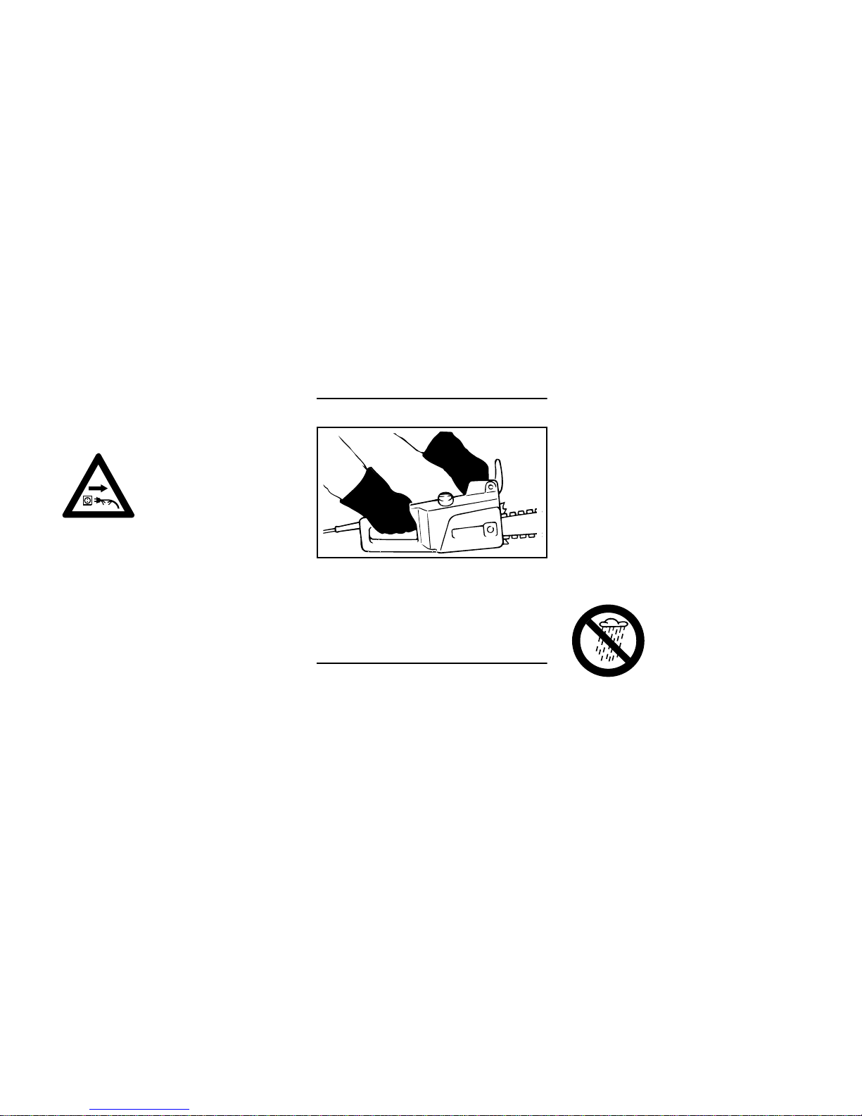
Holding and Controlling the Power Tool
Always hold your power tool firmly with
both hands: Right hand on the rear
handle, left hand on front handle, even if
you are left-handed.
During Operation
Make sure you always have good
balance and secure footing.
In case of imminent danger or in an
emergency, release the trigger switch
immediately.
Your power tool is designed to be
operated by one person only. Do not
allow other persons in the work area.
Position the connecting and extension
cords correctly:
– Do not chafe on edges, pointed or
sharp objects
– Do not squeeze through gaps in
doors or windows
– If cords are twisted – unplug the
power tool and straighten them out
– Always unwind the extension cord
completely from the cable drum to
reduce the risk of fire from
overheating.
– The extension cord must always be
behind you. To reduce the risk of
stumbling, position and mark the
cord so that it cannot be damaged
or endanger others.
– Keep the connecting cord so that it
cannot be touched by the rotating
chain.
When switching on, check that the chain
is not touching any object or the ground.
Do not leave you power tool out in the
rain and do not operate it as long as it is
damp.
Take special care in slippery conditions
– damp, snow, ice, on slopes, uneven
ground and freshly debarked logs.
Watch out for obstacles such as tree
stumps, roots and ditches which could
cause you to trip or stumble.
If the connecting cord is
damaged, immediately
disconnect the plug from
the power supply to avoid
the risk of electric shock.
001BA094 LA
The drive motor is not
waterproof. To reduce
the risk of a short circuit
or electrocution, never
work with the power tool
in the rain or in wet or
very damp locations.
Page 7
MSE 140 C, MSE 160 C, MSE 180 C, MSE 200 C
English
5
Do not work alone – keep within calling
distance of others in case help is
needed.
Be particularly alert and cautious when
wearing hearing protection because
your ability to hear warnings (shouts,
alarms, etc.) is restricted.
To reduce the risk of accidents, take a
break in good time to avoid tiredness or
exhaustion.
The dusts (e.g. sawdust) produced
during operation may be dangerous to
health. If dust levels are very high, wear
a suitable respirator.
Your power tool is equipped with a
system designed to quickly stop the saw
chain – it comes to an immediate
standstill as soon as you release the
trigger switch.
Check this function at regular short
intervals. Do not operate your chain saw
if the chain continues to run after you
release the trigger switch – see
"Coasting Brake" – risk of injury. Contact
your servicing dealer.
Never jerk the connecting cord to
disconnect it from the wall outlet. To
unplug, grasp the plug, not the cord.
Be sure your hands are dry before
touching the plug or power cord.
Check the saw chain at regular short
intervals during operation or
immediately if there is a noticeable
change in cutting behavior:
– Switch off the motor, wait for the
chain to come to a standstill,
disconnect the plug from the power
supply.
– Check condition and proper
mounting.
– Check sharpness.
Do not touch the chain while the engine
is running. If the chain becomes jammed
by an obstacle, switch off the motor
immediately and disconnect the plug
from the power supply before attempting
to free the obstruction.
Always switch off the motor and remove
the plug it from the wall outlet before
replacing the chain. This avoids the risk
of injury from the chain starting
unintentionally.
To reduce the risk of fire, do not smoke
while operating or standing near your
power tool.
Always unplug your power tool from the
wall outlet when it is not in use – this
helps avoid accidential start-up.
If your power tool is subjected to
unusually high loads for which it was not
designed (e.g. heavy impact or a fall),
always check that it is in good condition
before continuing work – see also
"Before Starting Work".
Make sure the safety devices are
working properly. Do not continue
operating your power tool if it is
damaged. In case of doubt, have the unit
checked by your servicing dealer.
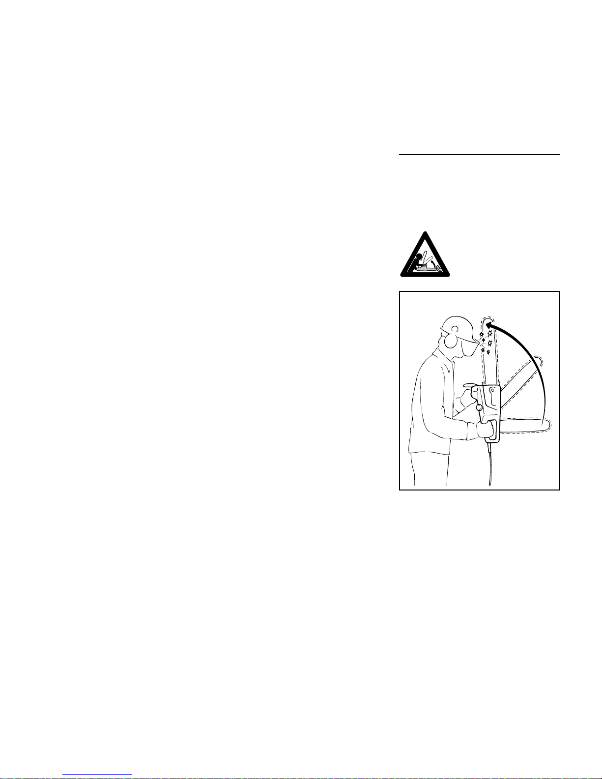
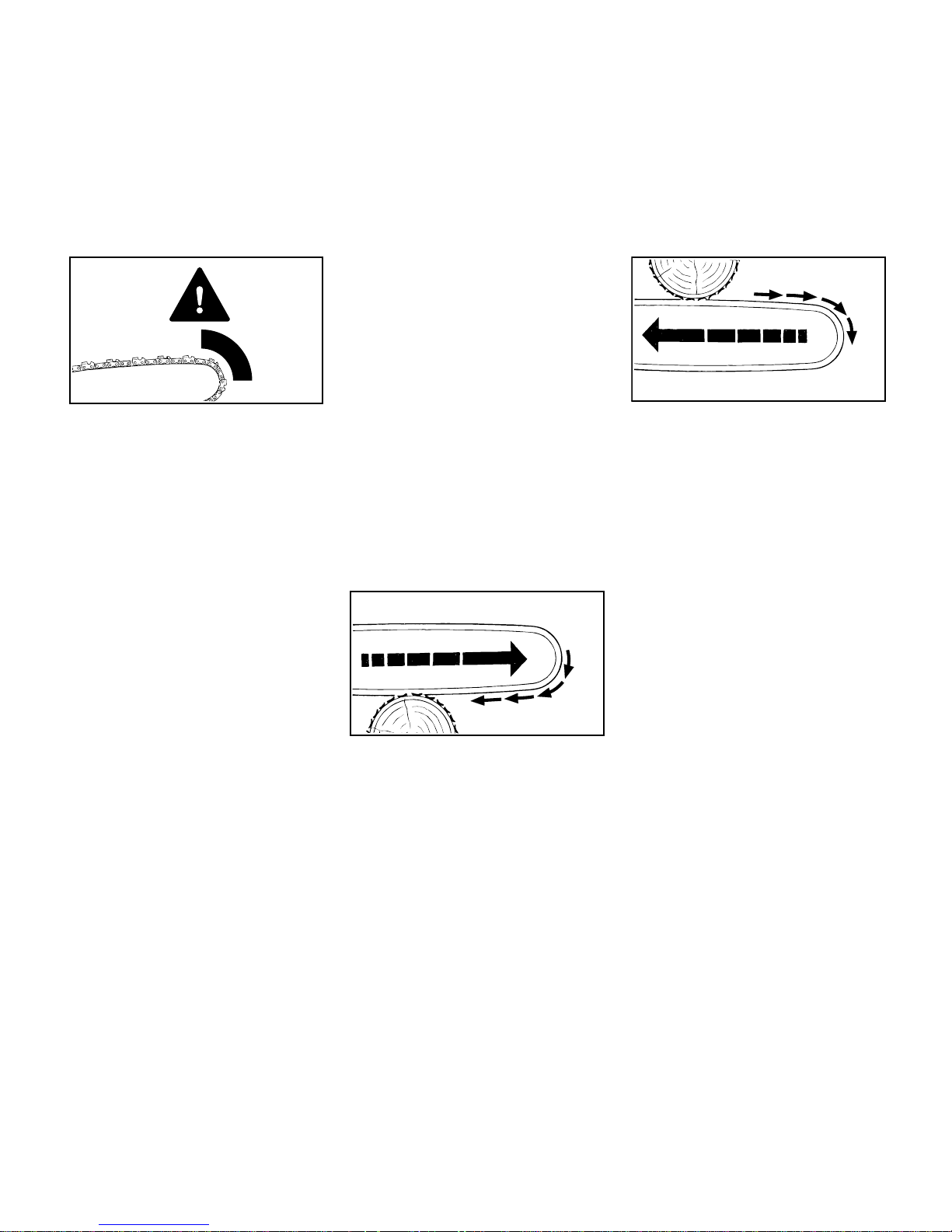
Reactive Forces
The most common reactive forces that
occur during cutting are: kickback,
pushback and pull-in.
Dangers of kickback
Kickback occurs when the saw is
suddenly thrown up and back in an
uncontrolled arc towards the operator.
Kickback can result in
serious or fatal injury.
001BA075 LÄ
Page 8
MSE 140 C, MSE 160 C, MSE 180 C, MSE 200 C
English
6
Kickback occurs, e.g.
– when the upper quadrant of the bar
nose unintentionally contacts wood
or another solid object, e.g. when
another limb is touched accidentally
during limbing.
– when the chain at the nose of the
guide bar is pinched in the cut.
QuickStop chain brake
This device reduces the risk of injury in
certain situations – it cannot prevent
kickback. If activated, the brake stops
the saw chain within a fraction of a
second – for a description of this device
refer to chapter on "Chain Brake" in this
manual.
To reduce the risk of kickback
– Work cautiously and avoid
situations which could cause
kickback.
– Hold the saw firmly with both hands
and maintain a secure grip.
– Be aware of the location of the guide
bar nose at all times.
– Do not cut with the bar nose.
– Take special care with small, tough
limbs, they may catch the chain.
– Never cut several limbs at once.
– Do not overreach.
– Never cut above shoulder height.
– Use extreme caution when re-
entering a previous cut.
– Do not attempt plunge cuts if you
are not experienced in this cutting
technique.
– Be alert for shifting of the log or
other forces that may cause the cut
to close and pinch the chain.
– Always cut with a correctly
sharpened, properly tensioned
chain – the depth gauge setting
must not be too large.
– Use a low kickback chain and a
narrow radius guide bar.
Pull-in (A)
Pull-in occurs when the chain on the
bottom of the bar is suddenly pinched,
caught or encounters a foreign object in
the wood. The reaction of the chain pulls
the saw forward – always hold the
spiked bumper securely against the tree
or limb.
Pushback (B)
Pushback occurs when the chain on the
top of the bar is suddenly pinched,
caught or encounters a foreign object in
the wood. The reaction of the chain
drives the saw straight back toward the
operator. To avoid pushback.
– Be alert to situations that may cause
the top of the guide bar to be
pinched
– Do not twist the guide bar in the cut.
Exercise extreme caution
– with leaners
– with trees that have fallen
unfavorably between other trees
and are under strain
Do not work with the chain saw in such
circumstances. Use block and tackle,
cable winch or tractor.
Pull out exposed and cleared logs.
Select clear area for cutting.
Deadwood (dry, decayed or rotted
wood) represents a considerable risk
that is difficult to assess. Identifying the
extent of the dangers is complicated, if
not impossible. Use aids such as a cable
winch or tractor in such cases.
001BA257 KN
001BA037 KN
A
001BA038 KN
B
Page 9
MSE 140 C, MSE 160 C, MSE 180 C, MSE 200 C
English
7
When felling in the vicinity of roads,
railways, power lines, etc., take extra
precautions. If necessary, inform the
police, utility company or railway
authority.
Cutting
Work calmly and carefully – in daylight
conditions and only when visibility is
good. Stay alert so as not to endanger
others.
Use the shortest possible guide bar: The
chain, guide bar and chain sprocket
must match each other and your saw.
Position the saw so that your body is
clear of the cutting attachment.
Use your chain saw for cutting only. It is
not designed for prying or shoveling
away limbs, roots or other objects.
Do not underbuck freely hanging limbs.
To reduce the risk of injury, take special
care when cutting shattered wood
because of the risk of injury from slivers
being caught and thrown in your
direction.
Make sure your power tool does not
touch any foreign materials: Stones,
nails, etc. may be flung off, damage the
saw chain or cause the saw to kick back
unexpectedly.
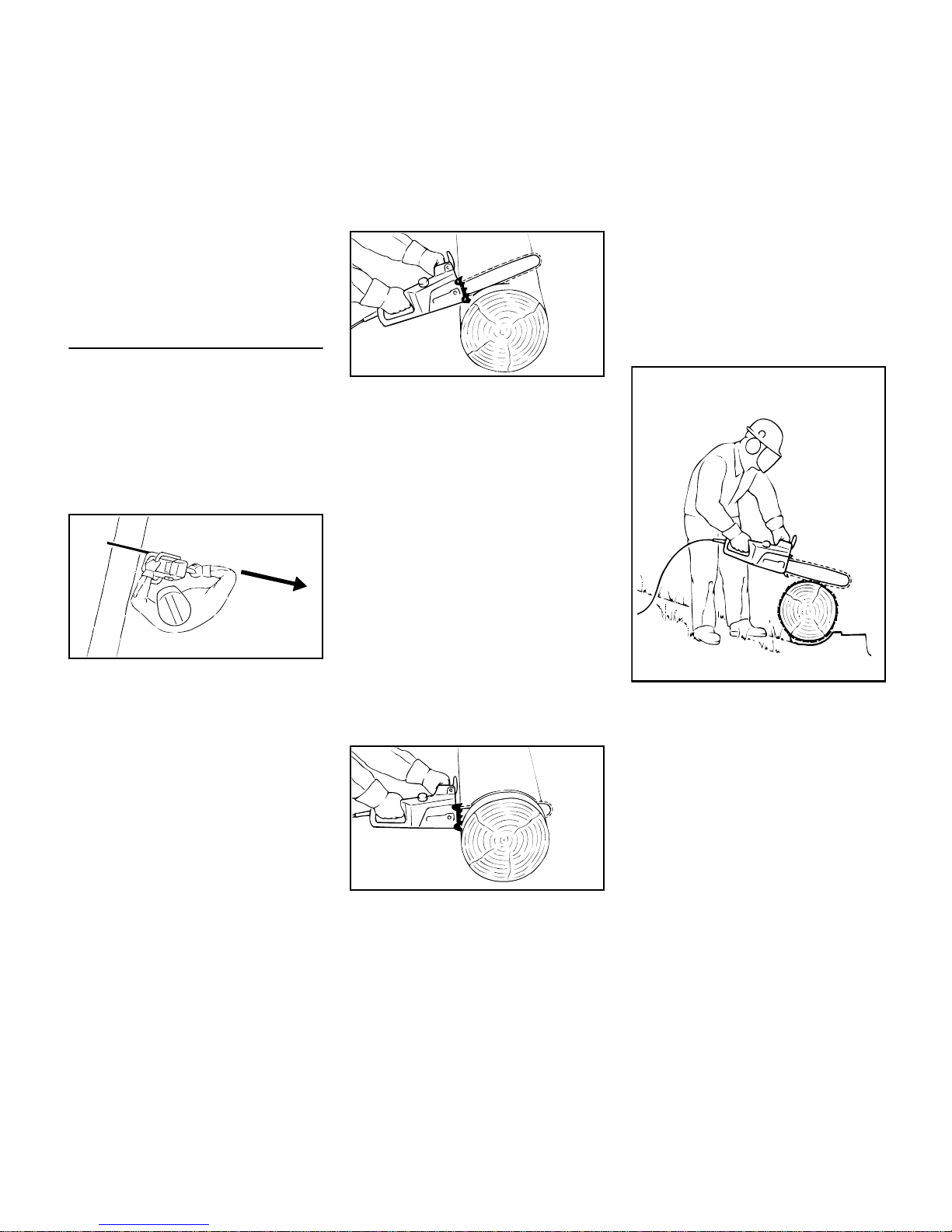
When cutting with the bottom of the
guide bar (overbucking): Never work
without the spiked bumper because the
saw may pull you forwards and off
balance. Always engage the spiked
bumper in the wood first and then start
cutting.
Start the cut with the chain running at full
speed.
Feed during the cut:
– Carefully raise the rear handle.
– Control the saw with the front
handle.
– Use the spiked bumper as a pivot.
Re-positioning in the cut:
– Carefully withdraw the saw until the
spiked bumper is clear of the log.
– Continue cutting by carefully
applying pressure to the front
handle.
– Re-engage the spiked bumper.
Always pull the saw out of the cut with
the chain running.
Note when reaching the end of a cut that
the saw is no longer supported in the
kerf. You have to take the full weight of
the unit since it might otherwise go out of
control.
If on a slope, stand on the uphill side of
the log. Watch out for rolling logs.
When working at heights:
– Always use a lift bucket
– Never work on a ladder or in a tree
– Never work on an insecure support
– Do not work above shoulder height
– Never operate your power tool with
one hand
001BA082 KN
001BA124 LA
001BA125 LA
001BA074 LÄ
Page 10
MSE 140 C, MSE 160 C, MSE 180 C, MSE 200 C
English
8
Felling
Do not attempt felling unless you have
been trained in the necessary
techniques. To reduce the risk of
accidents and injury, do not attempt
felling or limbing if you are not an
experienced chain saw user.
Gasoline chain saws are more suitable
than electric saws for felling and limbing.
The freedom of movement necessary for
this work is restricted by the connecting
cord.
Your electric chain saw is unsuitable for
cutting in blowdown areas and must not
be used for such work.
However, if a tree is to be felled and
limbed with an electric saw against this
recommendation, it is essential to
observe the following instructions.
Observe all country-specific regulations
on felling techniques.
Check that there are no other persons in
the felling area – other than helpers.
Make sure no-one is endangered by the
falling tree – the noise of your engine
may drown any warning calls.
Maintain a distance of at least 2 1/2 tree
lengths from the next felling site.
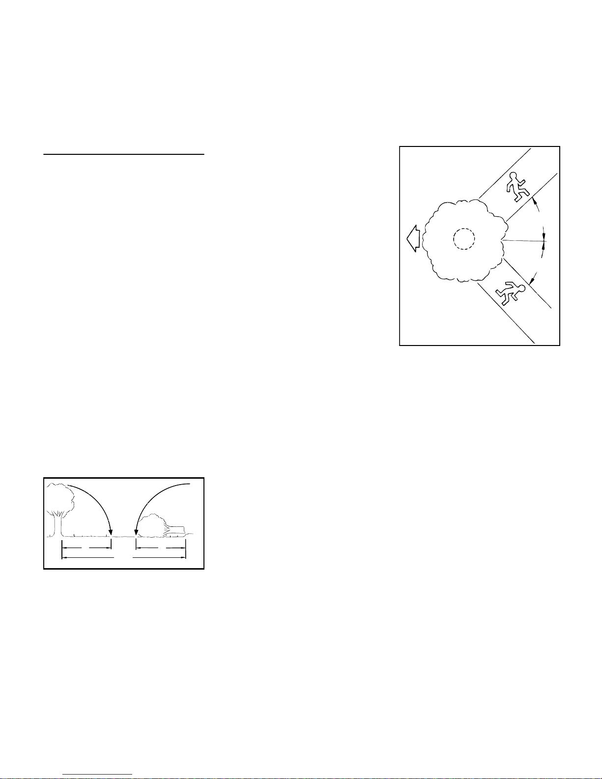
Determine direction of fall and escape
paths
Select gap in stand into which you want
the tree to fall.
Pay special attention to the following
points:
– The natural lean of the tree
– Any unusually heavy limb structure,
damage
– The wind direction and speed – do
not fell in high winds
– Sloping ground
– Neighboring trees
– Snow load
– Soundness of tree – take special
care if trunk is damaged or in case
of deadwood (dry, decayed or rotted
wood)
– The extension cord must not be
looped. It must be long enough to be
laid is wide-radius curves. It must
not be under tension and must lie
flat on the ground over its whole
length.
A Direction of fall
B Escape paths
– Establish paths of escape for
everyone concerned – opposite to
direction of fall at about 45°.
– Remove all obstacles from escape
paths.
– Place all tools and equipment a safe
distance away from the tree, but not
on the escape paths.
– Always keep to the side of the falling
tree and only walk away along the
preplanned escape path.
– On steep slopes, plan escape
routes parallel to the slope.
– When walking away along the
escape path, watch out for falling
limbs and watch the top of the tree.
001BA088 LÄ
2
/
1
2
1 1
/
1
2
B
001BA040 KN
A
45°
45°
B
Page 11
MSE 140 C, MSE 160 C, MSE 180 C, MSE 200 C
English
9
Preparing work area at base of tree
– First clear the tree base and work
area from interfering limbs and
brush to provide a secure footing.
– Clean lower portion of tree base
(e.g. with an axe) – sand, stones
and other foreign objects will dull the
saw chain.
– Remove large buttress roots: Make
the vertical cut first, then the
horizontal – but only if the wood is
sound
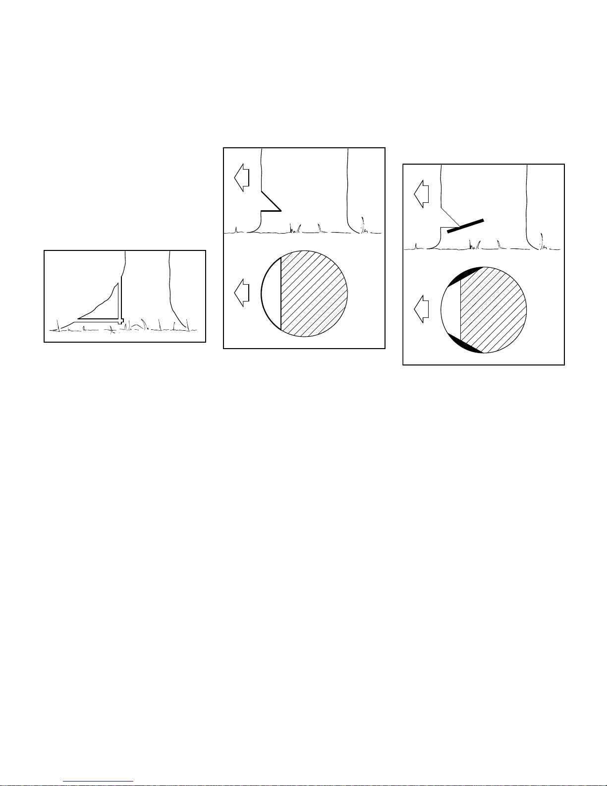
Making felling notch
There are several approved methods for
making the felling notch – observe
country-specific regulations on felling
techniques.
The felling notch (C) determines the
direction of fall.
STIHL recommends the following
method:
N Make the horizontal cut – check the
direction of fall.
N Make angle cut at about 45°.
N Check the felling notch and correct it
if necessary.
Important:
– Felling notch at a right angle to the
planned direction of fall.
– As close to the ground as possible.
– Cut to a depth of about 1/5 to 1/3 of
the trunk diameter.
Sapwood cuts
Sapwood cuts in long-fibered softwood
help prevent sapwood splintering when
the tree falls. Make cuts at both sides of
the trunk at same height as bottom of
felling notch to a depth of about 1/10 of
trunk diameter. On large diameter trees,
cut to no more than width of guide bar.
Do not make sapwood cuts if wood is
diseased.
001BA146 KN
001BA143 KN
C
C
001BA150 KN
Page 12
MSE 140 C, MSE 160 C, MSE 180 C, MSE 200 C
English
10
Felling
Shout a warning before starting the
felling cut.
N Make the felling cut (D) slightly
higher than bottom of the felling
notch.
– Cut horizontally.
– Leave approx. 1/10 of the tree
diameter uncut between the felling
cut and the felling notch. This is the
hinge.
Drive wedges into the felling cut in good
time. Use only wooden, aluminum or
plastic wedges. Never steel, which can
damage the chain and cause kickback.
The hinge (E) helps control the falling
tree.
– Do not cut through the hinge – you
could lose control of the direction of
fall – this could result in an accident.
– Leave a broader hinge on rotten
trees.
Shout a second warning immediately
before the tree falls.
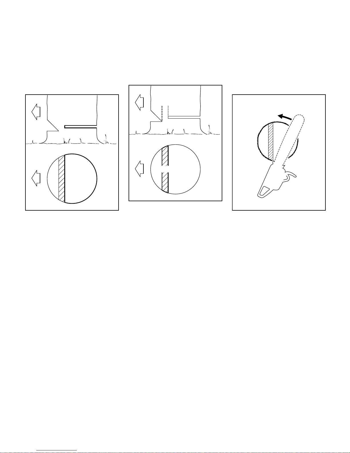
Small diameter trees: Simple fan cut
N Apply the spiked bumper behind the
hinge – pivot the saw around this
point - only as far as the hinge. The
spiked bumper rolls against the
trunk.
001BA144 KN
D
D
001BA145 KN
E
E
001BA147 KN
Page 13
MSE 140 C, MSE 160 C, MSE 180 C, MSE 200 C
English
11
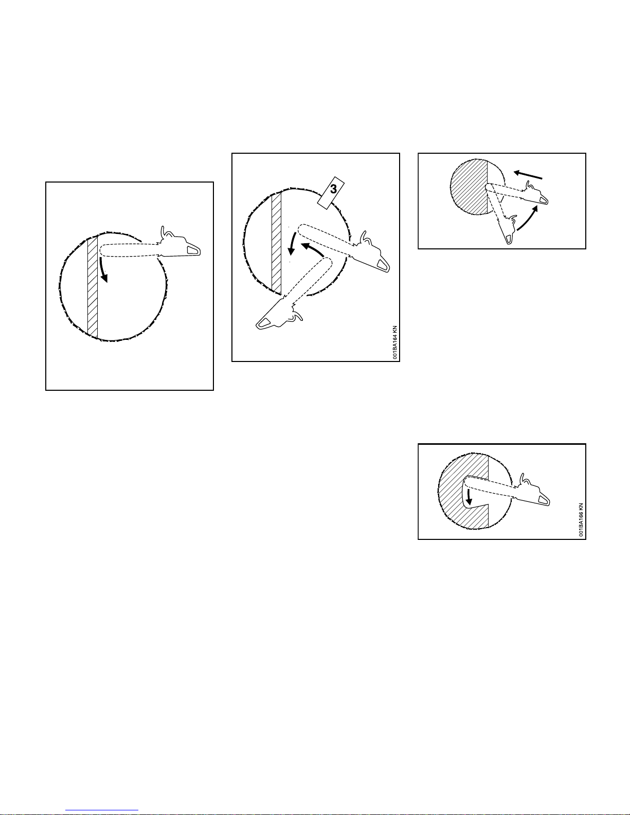
Large diameter trees: Sectioning
method
If the diameter of the tree is greater than
the length of the guide bar, use the
sectioning method.
1. First cut
Nose of guide bar should enter
wood just behind the hinge – hold
the saw horizontally and swing it as
far as possible, using the bumper
spike as a pivot – avoid
repositioning the saw more than
necessary.
2. When repositioning the saw for the
next cut, keep the guide bar fully
engaged in the kerf to keep the
felling cut straight – apply the spiked
bumper again, and so on.
3. Insert a wedge (3) in the cut.
4. Last cut: Apply the spiked bumper
as for the simple fan cut – do not cut
through the hinge.
Special cutting techniques
Plunge cuts and heartwood cuts require
special training and experience.
Plunge cutting
– For felling leaners
– For relieving cuts during bucking
– For DIY projects
N Use a low kickback chain and
exercise particular caution
1. Begin cut by applying the lower
portion of the guide bar nose – do
not use upper portion because of –
risk of kickback. Cut until depth of
kerf is twice the width of the guide
bar.
2. Swing saw slowly into plungecutting position – take care because
of the risk of kickback or pushback.
3. Make the plunge cut very carefully.
Danger of pushback.
Heartwood cut
– If tree diameter is more than twice
the length of the guide bar.
– If a large portion of heartwood
remains uncut on large diameter
trees.
001BA148 KN
1
4
2
1
2
3
001BA179 KN
Page 14
MSE 140 C, MSE 160 C, MSE 180 C, MSE 200 C
English
12
– On trees that are difficult to fell (oak,
beech), to prevent heartwood
splintering and maintain planned
direction of fall.
– On soft deciduous trees to relieve
tension in lying log and prevent
slivers in the center of the hinge
being torn out of the log.
N Make the plunge cut in the center of
the felling notch – there is a danger
of pushback at this point – then
swing the bar in the direction of the
arrow.
Limbing
Do not attempt limbing unless you have
been trained in the necessary
techniques. To reduce the risk of
accidents and injury, do not attempt
felling or limbing if you are not an
experienced chain saw user.
– Use a low kickback chain.
– Work with the saw supported
wherever possible.
– Do not stand on the log while
limbing it.
– Do not cut with the bar nose.
– Watch for limbs which are under
tension.
– Never cut several limbs at once.
– The extension cord must not be
looped. It must be long enough to be
laid is wide-radius curves. It must
not be under tension and must lie
flat on the ground over its whole
length.
When cutting small logs
– Use a sturdy and stable support –
sawhorse.
– Never hold the log with your leg or
foot.
– Never allow another person to hold
the log or help in any other way.
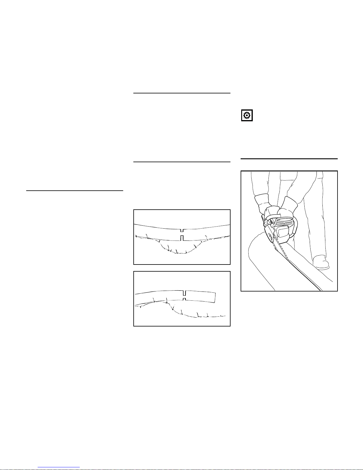
Lying or standing logs under tension
Always make cuts in the correct
sequence (first at the compression
side (1), then at the tension side (2), the
saw may otherwise pinch or kick back –
risk of injury.
N Make relieving cut at the
compression side (1)
N Make bucking cut at the tension
side (2)
Be wary of pushback when making
bucking cut from the bottom upwards
(underbuck).
NOTICE
Do not cut a lying log at a point where it
is touching the ground because the saw
chain will otherwise be damaged.
Ripping cut
Cutting technique in which the spiked
bumper is not used – risk of pull-in – start
the cut with the guide bar at the
shallowest possible angle – take extra
care since there is an increased danger
of kickback.
1
001BA151 KN
2
1
001BA152 KN
2
001BA189 KN
Page 15

MSE 140 C, MSE 160 C, MSE 180 C, MSE 200 C
English
13
Vibrations
Prolonged use of the power tool may
result in vibration-induced circulation
problems in the hands (whitefinger
disease).
No general recommendation can be
given for the length of usage because it
depends on several factors.
The period of usage is prolonged by:
– Hand protection (wearing warm
gloves)
– Work breaks
The period of usage is shortened by:
– Any personal tendency to suffer
from poor circulation (symptoms:
frequently cold fingers, tingling
sensations).
– Low outside temperatures.
– The force with which the handles
are held (a tight grip restricts
circulation).
Continual and regular users should
monitor closely the condition of their
hands and fingers. If any of the above
symptoms appear (e.g. tingling
sensation in fingers), seek medical
advice.
Maintenance and Repairs
Always switch off the machine and
disconnect it from the wall outlet before
performing any maintenance work. This
avoids the risk of injury from the chain
starting unintentionally.
Service the machine regularly. Do not
attempt any maintenance or repair work
not described in the instruction manual.
Have all other work performed by a
servicing dealer.
STIHL recommends that you have
servicing and repair work carried out
exclusively by an authorized STIHL
servicing dealer. STIHL dealers are
regularly given the opportunity to attend
training courses and are supplied with
the necessary technical information.
Only use high-quality replacement parts
in order to avoid the risk of accidents
and damage to the unit. If you have any
questions in this respect, consult a
servicing dealer.
STIHL recommends the use of genuine
STIHL replacement parts. They are
specifically designed to match your
model and meet your performance
requirements.
Never attempt to modify your power tool
in any way since this will increase the
risk of personal injury.
Regularly check that the insulation of the
power cord and plug is in good condition
and shows no sign of ageing
(brittleness).
Electrical components, e.g. power cord,
may only be repaired or replaced by a
qualified electrician.
Check the chain catcher and r eplac e it if
damaged.
Observe sharpening instructions – keep
the chain and guide bar in good
condition at all times for safe and correct
handling of the saw. The chain must be
properly sharpened, tensioned and well
lubricated.
Always change the chain, guide bar and
sprocket in good time.
Store chain lubricant in properly
labelled, safety-type canisters only.
To reduce the risk of injury, shut off the
saw immediately if the chain brake
malfunctions – contact your servicing
dealer – do not use your saw until the
problem has been rectified (see "Chain
Brake").
Clean plastic surfaces with a cloth. Do
not use aggressive detergents. They
may damage the plastic.
Page 16

MSE 140 C, MSE 160 C, MSE 180 C, MSE 200 C
English
14
STIHL is the only manufacturer in the
industry to produce its own chain saws,
guide bars, saw chains and chain
sprockets.
A cutting attachment consists of the saw
chain, guide bar and chain sprocket.
The cutting attachment that comes
standard is designed to exactly match
the chain saw.
– The pitch (t) of the saw chain (1),
chain sprocket and the nose
sprocket of the Rollomatic guide bar
must match.
– The drive link gauge (2) of the saw
chain (1) must match the groove
width of the guide bar (3).
If non-matching components are used,
the cutting attachment may be damaged
beyond repair after a short period of
operation.
Chain Scabbard
Your saw comes standard with a chain
scabbard that matches the cutting
attachment.
If guide bars of different lengths are
mounted to the saw, always use a chain
scabbard of the correct length which
covers the complete guide bar.
The length of the matching guide bars is
marked on the side of the chain
scabbard.
WARNING
Do not connect the power tool to the wall
outlet yet.
Removing the chain sprocket cover
N Unscrew the nut and remove the
chain sprocket cover.
N Turn the screw (1)
counterclockwise until the
tensioning nut (2) butts against the
left end of the housing slot.
Cutting Attachment
001BA248 KN
1
2
3
a
001BA244 KN
Mounting the Bar and Chain
(front chain tensioner)
100BA001 KN
2
1
181BA009 KN
Page 17

MSE 140 C, MSE 160 C, MSE 180 C, MSE 200 C
English
15
Disengaging the chain brake.
N Pull the hand guard towards the
front handle until there is an audible
click – the chain brake is
disengaged.
Fitting the chain
WARNING
Wear work gloves to protect your hands
from the sharp cutters.
N Fit the chain – start at the bar nose.
N Turn the guide bar so that the chain
is positioned as shown in the
pictogram (1).
N Fit the guide bar over the studs (2)
and engage the tensioning nut in the
hole (3) – place the chain over the
sprocket (4) at the same time.
N Turn the tensioning screw (5)
clockwise until there is very little
chain sag on the underside of the
bar – and the drive link tangs are
engaged in the bar groove.
N Refit the sprocket cover and screw
on the nut fingertight.
N The arrow (6) indicates the direction
of chain rotation.
N Go to chapter on "Tensioning the
Saw Chain"
WARNING
Do not connect the power tool to the wall
outlet yet.
Removing the chain sprocket cover
N Unscrew the nut and remove the
chain sprocket cover.
N Turn the screw (1)
counterclockwise until the
tensioning nut (2) butts against the
left end of the housing slot.
181BA010 KN
143BA003 KN
181BA019 KN
6
5
4
2
1
2
3
Mounting the Bar and Chain
(side chain tensioner)
100BA001 KN
1
2
181BA008 KN
Page 18

MSE 140 C, MSE 160 C, MSE 180 C, MSE 200 C
English
16
Disengaging the chain brake.
N Pull the hand guard towards the
front handle until there is an audible
click – the chain brake is
disengaged.
Fitting the chain
WARNING
Wear work gloves to protect your hands
from the sharp cutters.
N Fit the chain – start at the bar nose.
N Turn the guide bar so that the chain
is positioned as shown in the
pictogram (1).
N Fit the guide bar over the studs (2)
and engage the tensioning nut in the
hole (3) – place the chain over the
sprocket (4) at the same time.
N Turn the tensioning screw (5)
clockwise until there is very little
chain sag on the underside of the
bar – and the drive link tangs are
engaged in the bar groove.
N Refit the sprocket cover and screw
on the nut fingertight.
N The arrow (6) indicates the direction
of chain rotation.
N Go to chapter on "Tensioning the
Saw Chain"
WARNING
Do not connect the power tool to the wall
outlet yet.
Removing the chain sprocket cover
N Pull out the hinged clip (1) so that it
snaps into position.
N Turn the wingnut (2)
counterclockwise until it hangs
loose in the sprocket cover (3).
N Remove the chain sprocket
cover (3).
Fitting the tensioning gear
N Remove the tensioning gear (4) and
turn it over.
181BA010 KN
143BA003 KN
6
181BA011 KN
5
4
2
1
2
3
Mounting the Bar and Chain
(quick chain tensioner)
1
2
3
100BA028 KN
4
100BA007 KN
Page 19

MSE 140 C, MSE 160 C, MSE 180 C, MSE 200 C
English
17
N Take out the screw (5).
N Line up the tensioning gear (6) and
guide bar (7).
N Insert the screw (8) and tighten it
down firmly.
Disengaging the chain brake.
N Pull the hand guard towards the
front handle until there is an audible
click – the chain brake is
disengaged.
Fitting the chain
WARNING
Wear work gloves to protect your hands
from the sharp cutters.
N Fit the chain – start at the bar nose.
Pay attention to the position of the
tensioning gear and the cutting
edges.
N Turn the tensioning gear (1)
clockwise as far as stop.
N Turn the guide bar so that the
tensioning gear is facing you.
N Fit the chain over the sprocket (2).
N Push the guide bar over the bar
stud (3), the head of the rear bar
stud must engage the slot.
5
135BA005 KN
6
7
135BA006 KN
8
135BA007 KN
181BA010 KN
1
181BA012 KN
2
3
181BA013 KN
Page 20

MSE 140 C, MSE 160 C, MSE 180 C, MSE 200 C
English
18
N Make sure the drive link tangs
engage the bar groove (arrow) and
then rotate the tensioning gear
counterclockwise as far as stop.
N Place the chain sprocket cover in
position and engage the guide lugs
in the recesses in the engine
housing.
When fitting the chain sprocket cover,
check that the teeth of the tensioning
gear and adjusting wheel mesh properly.
N If necessary, turn the adjusting
wheel (4) slightly until the sprocket
cover can be pushed flush against
the engine housing.
N Pull out the hinged clip (5) so that it
snaps into position.
N Engage wingnut and tighten it down
moderately.
N Go to chapter on "Tensioning the
Saw Chain"
Retensioning during cutting work:
N Disconnect the plug from the wall
outlet.
N Loosen the nut.
N Hold the bar nose up.
N Use a screwdriver to turn the
tensioning screw (1) clockwise until
the chain fits snugly against the
underside of the bar.
N While still holding the bar nose up,
tighten down the nut firmly.
N Go to "Checking Chain Tension".
A new chain has to be retensioned more
often than one that has been in use for
some time.
N Check chain tension frequently –
see chapter on "Operating
Instructions".
100BA009 KN
100BA010 KN
4
5
181BA014 KN
Tensioning the Saw Chain
(front chain tensioner)
1
180BA015 KN
Page 21

MSE 140 C, MSE 160 C, MSE 180 C, MSE 200 C
English
19
Retensioning during cutting work:
N Disconnect the plug from the wall
outlet.
N Loosen the nut.
N Hold the bar nose up.
N Use a screwdriver to turn the
tensioning screw (1) clockwise until
the chain fits snugly against the
underside of the bar.
N While still holding the bar nose up,
tighten down the nut firmly.
N Go to "Checking Chain Tension".
A new chain has to be retensioned more
often than one that has been in use for
some time.
N Check chain tension frequently –
see chapter on "Operating
Instructions".
Retensioning during cutting work:
N Disconnect the plug from the wall
outlet.
N Pull out the hinged grip and loosen
the wingnut.
N Turn the adjusting wheel (1)
clockwise as far as stop.
N Tighten down the wingnut (2) firmly
by hand.
N Fold down the hinged grip.
N Go to "Checking Chain Tension".
A new chain has to be retensioned more
often than one that has been in use for
some time.
N Check chain tension frequently –
see chapter on "Operating
Instructions".
N Disconnect the plug from the wall
outlet.
N Wear work gloves to protect your
hands.
N Disengage the chain brake: Pull the
hand guard (1) against the front
handle and hold it there – the chain
brake and coasting brake are
disengaged in this position.
N The chain must fit snugly against
the underside of the bar and it must
still be possible to pull the chain
along the bar by hand.
N If necessary, retension the chain.
A new chain has to be retensioned more
often than one that has been in use for
some time.
N Check chain tension frequently –
see chapter on "Operating
Instructions".
Tensioning the Saw Chain
(side chain tensioner)
1
180BA016 KN
Tensioning the Saw Chain
(quick chain tensioner)
1
2
100BA013 KN
Checking Chain Tension
100BA015 KN
1
Page 22

MSE 140 C, MSE 160 C, MSE 180 C, MSE 200 C
English
20
For automatic and reliable lubrication of
the chain and guide bar – use only an
environmentally compatible quality
chain and bar lubricant. Rapidly
biodegradable STIHL Bioplus is
recommended.
NOTICE
Biological chain oil must be resistant to
aging (e.g. STIHL Bioplus) since it will
otherwise quickly turn to resin. This
results in hard deposits that are difficult
to remove, especially in the area of the
chain drive and chain. It may even cause
the oil pump to seize.
The service life of the chain and guide
bar depends on the quality of the
lubricant. It is therefore essential to use
only a specially formulated chain
lubricant.
WARNING
Do not use waste oil. Renewed contact
with waste oil can cause skin cancer.
Moreover, waste oil is environmentally
harmful.
NOTICE
Waste oil does not have the necessary
lubricating properties and is unsuitable
for chain lubrication.
Preparations
N Thoroughly clean the oil filler cap (1)
and the area around it to ensure that
no dirt falls into the tank.
N Position the machine so that the
filler cap is facing up.
N Open the filler cap.
Filling the Chain Oil Tank
N Fill up with chain oil.
Take care not to spill chain oil while
refilling and do not overfill the tank.
N Close the filler cap.
N Check the oil level regularly during
operation.
N Top up the oil tank when the oil level
reaches the "min" mark (2) or
earlier.
If the oil level in the tank does not go
down, the reason may be a fault in the oil
supply system: Check chain lubrication,
clean the oilways, contact your dealer
for assistance if necessary STIHL
recommends that you have servicing
and repair work carried out exclusively
by an authorized STIHL servicing
dealer.
Chain Lubricant Filling Chain Oil Tank
1
2
181BA017 KN
Page 23

MSE 140 C, MSE 160 C, MSE 180 C, MSE 200 C
English
21
The saw chain must always throw off a
small amount of oil.
NOTICE
Never operate your saw without chain
lubrication. If the chain runs dry, the
whole cutting attachment will be
irretrievably damaged within a very short
time. Always check chain lubrication and
the oil level in the tank before starting
work.
Every new chain has to be broken in for
about 2 to 3 minutes.
After breaking in the chain, check chain
tension and adjust if necessary – see
"Checking Chain Tension".
The coasting brake brings the running
chain to a standstill when you let go of
the trigger switch.
1 Coasting brake stops the running
chain.
2 Coasting brake disengaged.
Locking the chain
– in an emergency
The chain brake is activated by pushing
the hand guard toward the bar nose with
your left hand – or by inertia in certain
kickback situations: The chain is
stopped and locked.
Disengage the chain brake.
N Pull the hand guard back toward the
front handle.
Checking Chain Lubrication
143BA024 KN
Coasting Brake
1
2
100BA019 KN
Chain Brake
181BA018 KN
181BA010 KN
Page 24

MSE 140 C, MSE 160 C, MSE 180 C, MSE 200 C
English
22
The chain brake is also activated by the
inertia of the front hand guard if the
kickback force of the saw is high
enough: The hand guard is accelerated
toward the bar nose – even if your left
hand is not behind the hand guard, e.g.
during a horizontal cut.
The chain brake will operate only if the
hand guard has not been modified in any
way.
Checking operation of the chain brake
Before starting work:
N Disengage the chain brake.
N Switch on the motor.
N Push the hand guard towards the
bar nose.
The chain brake is working properly if
the saw chain comes to a standstill
within a few fractions of a second.
The hand guard must be free from dirt
and move freely.
Chain brake maintenance
The chain brake is subject to normal
wear. It is necessary to have it serviced
and maintained regularly by trained
personnel. STIHL recommends that you
have servicing and repair work carried
out exclusively by an authorized STIHL
servicing dealer. Maintain the following
servicing intervals:
The voltage and frequency of the
machine (see rating plate) must match
the voltage and frequency of the power
connection.
The minimum fuse protection of the
power connection must comply with the
specifications – see "Specifications".
The machine must be connected to the
power supply via an earth-leakage
circuit breaker to disconnect the power
supply if the differential current to earth
exceeds 30 mA.
The power connection must correspond
to IEC 60364 and relevant national
regulations.
Depending on the supply voltage and
cord length, the minimum conductor
cross section of the extension cord must
be as follows:
Connecting to Wall Outlet
N Connect the power tool's plug or the
extension cord's plug to a properly
installed wall outlet.
N Make sure you have a firm footing.
N Check that bystanders are well clear
of the general work area of the
power tool.
N Hold the power tool firmly with both
hands on the handles.
N Disengage the chain brake by
pulling the hand guard back towards
the front handle.
N Check that the saw chain chain is
not touching the wood or any other
object.
N Press the lockout button (1) with
your thumb.
N Squeeze the trigger switch (2) with
your index finger.
N Start the cut with the chain running.
Full-time usage: every 3 months
Part-time usage: every 6 months
Occasional usage: every 12
months
Connecting to Power Supply
Cord length Minimum cross
section
220 V – 240 V:
up to 20 m 1.5 mm
2
20 m to 50 m 2.5 mm
2
100 V – 127 V:
up to 10 m AWG 14 / 2.0 mm
2
10 m to 30 m AWG 12 / 3.5 mm
2
Switching On
100BA020 KN
2
1
Page 25

MSE 140 C, MSE 160 C, MSE 180 C, MSE 200 C
English
23
N Release the trigger switch so that it
can return to the off position (1). It is
locked in this position by the trigger
switch lockout.
The coasting brake brings the chain to a
standstill.
WARNING
If the trigger switch is held in position 2,
the coasting brake is not activated and
the chain will continue running for
several seconds.
During longer work breaks – disconnect
the plug from the power supply.
When the machine is not in use, shut it
off so that it does not endanger others.
Secure it against unauthorized use.
The overload cutout interrupts the power
suppy to the saw in the case of
mechanical overload due to, e.g.
– excessive infeed force
– "lugging down" the motor
– pinching the saw chain in the cut
If the overload cutout has interrupted the
power supply:
N Pull the guide bar out of the cut.
N If necessary, disengage the chain
brake – see "Chain Brake".
MSE 140 C, MSE 160 C, MSE 180 C
N Wait for the overload cutout to cool
down.
N Press the pushbutton (1) – if the
motor does not run when you switch
on, the overload cutout has not yet
cooled down sufficiently – wait a
while and then press in the
pushbutton again as far as stop.
When the motor restarts:
N Run the motor off-load for about 15
seconds. This cools the motor and
helps prevent the overload cutout
tripping again.
MSE 200 C
The MSE 200 C is equipped with an
electronic overload cutout to monitor
motor temperature and power
consumption.
N The indicator lamp (1) comes on in
the event of overload and the power
supply is interrupted – the lamp
goes off after about 2 seconds and
the machine is again ready for
operation.
N Run the motor off-load for about 15
seconds. This cools the motor and
helps prevent the overload cutout
tripping again.
The indicator lamp glows only as long as
the trigger switch is operated.
The indicator lamp flashes briefly to
confirm it is functioning every time the
motor is switched on.
Switching Off
1
2
100BA019 KN
Overload Cutout
100BA029 KN
1
100BA030 KN
1
Page 26

MSE 140 C, MSE 160 C, MSE 180 C, MSE 200 C
English
24
During operation
N Check level in chain oil tank.
N Top up with chain oil when the "min"
mark is reached, or earlier – see
"Filling the Chain Oil Tank".
Check chain tension frequently
A new chain has to be retensioned more
often than one that has been in use for
some time.
Chain cold
Tension is correct when the chain fits
snugly against the underside of the bar
and can still be pulled along the bar by
hand. Retension if necessary – see
"Tensioning the Saw Chain".
Chain at operating temperature
The chain stretches and begins to sag.
The drive links must not come out of the
bar groove – the chain may otherwise
jump off the bar. Retension the chain –
see "Tensioning the Saw Chain".
NOTICE
The chain contracts as it cools down. If it
is not slackened off, it can damage the
drive shaft and bearings.
After finishing work
N Disconnect the plug from the wall
outlet.
N Slacken off the chain if you have
retensioned it at operating
temperature during cutting work.
NOTICE
Always slacken off the chain after
finishing work. The chain contracts as it
cools down. If it is not slackened off, it
can damage the drive shaft and
bearings.
Storing for a long period
See chapter on "Storing the Machine"
N Flip the bar – after each sharpening
and each time the chain is changed
– to avoid uneven wear, especially
at the sprocket nose and on the
bottom
N Periodically clean the oil inlet
hole (1), oil outlet channel (2) and
bar groove (3)
N Measure groove depth – using the
measuring tool on the file gauge
(special accessory) – in the area
with the greatest wear
Operating Instructions Taking Care of the Guide Bar
2
3
1
143BA026 KN
Page 27

MSE 140 C, MSE 160 C, MSE 180 C, MSE 200 C
English
25
If the groove is not at least this deep:
N Replace guide bar
Otherwise the drive links will grind
against the base of the groove – the
bottoms of the cutters and the tie straps
will not lie against the bar.
N Use a dry brush or similar tool to
clean the cooling slots at regular
intervals.
For periods of 3 months or longer
N Disconnect the plug from the wall
outlet.
N Remove the saw chain and guide
bar, clean them and spray with
corrosion inhibiting oil.
N Thoroughly clean the machine,
especially the cooling air inlets.
N If you use a biological chain and bar
lubricant, e.g. STIHL BioPlus,
completely fill the chain oil tank.
N Store the machine in a dry and
secure location – out of the reach of
children and other unauthorized
persons.
Chain type Chain pitch Minimum
groove depth
Picco 1/4“ P 4.0 mm
Rapid 1/4“ 4.0 mm
Picco 3/8“ P 5.0 mm
Rapid 3/8“; 0.325“ 6.0 mm
Rapid 0.404“ 7.0 mm
Motor Cooling
100BA027 KN
Storing the Machine
Page 28

MSE 140 C, MSE 160 C, MSE 180 C, MSE 200 C
English
26
N Disconnect the plug from the wall
outlet.
N Remove the chain sprocket cover,
chain and guide bar.
Replace the chain sprocket
– after using two saw chains or
sooner
– if the wear marks (a) on the sprocket
are deeper than approx. 0.5 mm
since this would reduce the life of
the chain. You can use a gauge
(special accessory) to check the
depth of the wear marks.
It is best to use two saw chains in
rotation with one sprocket.
STIHL recommends the use of original
STIHL sprockets to ensure correct
operation of the chain brake.
N Ease the E-clip (1) off the shaft.
N Remove and inspect the washer (2)
– replace it if it shows signs of wear.
N Remove the chain sprocket (3).
N Install the new chain sprocket in the
reverse sequence.
Cutting effortlessly with a correctly
sharpened chain
A properly sharpened chain slices
through wood effortlessly and requires
very little feed pressure.
Do not work with a dull or damaged
chain as it will increase the physical
effort required, produce unsatisfactory
results and a higher rate of wear.
N Clean the chain.
N Check the chain for cracks in the
links and damaged rivets.
N Replace any damaged or worn
parts of the chain and match the
new parts to the shape and size of
the original parts.
Carbide-tipped saw chains (Duro) are
particularly wear resistant. STIHL
recommends you have your chain
resharpened by a STIHL servicing
dealer.
WARNING
It is absolutely essential to comply with
the angles and dimensions specified
below. If the saw chain is incorrectly
sharpened – and in particular if the depth
gauge is set too low – there is a risk of
increased kickback of the saw, with
resulting risk of injury.
Checking and Replacing the
Chain Sprocket
a
000BA054 KN
1
2
3
100BA026 KN
Maintaining and Sharpening
the Saw Chain
Page 29

MSE 140 C, MSE 160 C, MSE 180 C, MSE 200 C
English
27
Chain pitch
The chain pitch (a) is marked on the
depth gauge end of each cutter.
Select file diameter according to chain
pitch – see table “Sharpening Tools”.
You must observe certain angles when
resharpening the chain cutter.
Filing and side plate angles
A Filing angle
STIHL saw chains are sharpened to a
filing angle of 30°. Exceptions are
ripping chains with a filing angle of 10°.
Ripping chains have an X in their
designations.
B Side plate angle
The correct side plate angle is obtained
automatically if you use the prescribed
file holder and file diameter.
The angles must be the same on all
cutters. If the angles are uneven: Chain
will run roughly, not in a straight line,
wear quickly and finally break.
File holder
N Use a file holder
A file holder must be used for manual
resharpening (see table "Sharpening
Tools"). The correct filing angles are
marked on the file holder.
Use only special saw chain sharpening
files. Other files have the wrong shape
and cut.
For checking angles
Use a STlHL filing gauge (special
accessory, see table "Sharpening
Tools"). This is a universal tool for
checking the filing and side plate angles,
depth gauge setting, cutter length and
groove depth. It also cleans the guide
bar groove and oil inlet holes.
File correctly
N Disconnect the plug from the wall
outlet.
N Select sharpening tools according
to chain pitch.
N Clamp the bar in a vise if necessary.
N To rotate the chain – pull hand
guard against handle to disengage
the chain brake Hold the hand guard
in this position – the coasting brake
is disengaged.
N Sharpen the chain frequently, take
away as little metal as possible –
two or three strokes of the file are
usually enough.
Mark (a) Chain pitch
inch mm
7 1/4 P 6,35
1 or 1/4 1/4 6,35
6, P or PM 3/8 P 9,32
2 or 325 0.325 8,25
3 or 3/8 3/8 9,32
4 or 404 0.404 10,26
689BA027 KN
a
A
B
689BA021 KN
Cutter shapes Angle (°)
AB
Micro = semi chisel cutter,
e.g. 63 PM3, 26 RM3,
36 RM
30 75
Super = chisel cutter, e.g.
63 PS3, 26 RS, 36 RS3
30 60
Ripping chain, e.g.
63 PMX, 36 RMX
10 75
689BA025 KN
001BA203 KN
Page 30

MSE 140 C, MSE 160 C, MSE 180 C, MSE 200 C
English
28
N Hold the file horizontally (at a right
angle to the side of the guide bar)
and file according to the angles
marked on the file holder. Rest the
file holder on the top plate and depth
gauge.
N Always file from the inside to the
outside of the cutter.
N The file only sharpens on the
forward stroke – lift the file off the
cutter on the backstroke.
N Avoid touching the tie straps and
drive links with the file.
N Rotate the file at regular intervals
while filing to avoid one-sided wear.
N Use a piece of hardwood to remove
burrs from the cutting edge.
N Check angles with the filing gauge.
All cutters must be the same length.
If the cutters are not the same length,
they will have different heights. This
makes the chain run roughly and can
cause it to break.
N Find the shortest cutter and then file
all other cutters back to the same
length. It is best to have this work
done by a servicing dealer on an
electric grinder.
Depth gauge setting
The depth gauge determines the height
at which the cutter enters the wood and
thus the thickness of the chip removed.
a Specified distance or setting
between depth gauge and cutting
edge.
This setting may be increased by
0.2 mm (0.008") for cutting softwood in
the mild weather season – no frost.
Lowering depth gauges
The depth gauge setting is reduced
when the chain is sharpened.
N Use a filing gauge to check the
setting every time you sharpen the
chain.
N Place a filing gauge (1) that
matches the chain pitch on the
chain and press it against the cutter
– if the depth gauge projects from
the filing gauge, the depth gauge
has to be lowered.
Saw chains with humped drive link (2) –
upper part of humped drive link (2) (with
service mark) is lowered along with the
depth gauge.
WARNING
The other parts of the humped drive link
must not be filed since this may increase
the kickback tendency of the saw.
689BA018 KN
90°
689BA043 KN
Chain pitch Depth gauge
Setting (a)
inch (mm) mm (inch)
1/4 P (6,35) 0,45 (0.018)
1/4 (6,35) 0,65 (0.026)
3/8 P (9,32) 0,65 (0.026)
0.325 (8,25) 0,65 (0.026)
3/8 (9,32) 0,65 (0.026)
0.404 (10,26) 0,80 (0.031)
689BA023 KN
a
2
689BA061 KN
1
Page 31

MSE 140 C, MSE 160 C, MSE 180 C, MSE 200 C
English
29
N File down the depth gauge until it is
level with the filing gauge.
N File the top of the depth gauge
parallel to the stamped service
marking (see arrow) – but do not
lower the highest point of the depth
gauge in this process.
WARNING
The kickback tendency of the saw is
increased if the depth gauges are too
low.
N Place the filing gauge on the chain –
the highest point of the depth gauge
must be level with the filing gauge.
N After sharpening, clean the chain
thoroughly, remove filings or
grinding dust – lubricate the chain
thoroughly.
N Before a long out-of-service period,
clean the chain and store it in a welloiled condition.
689BA051 KN
689BA044 KN
689BA052 KN
Sharpening Tools (special accessories)
Chain pitch Round file ^ Round file File holder Filing gauge Flat file Sharpening kit
1)
inch (mm) mm (inch) Part No. Part No. Part No. Part No. Part No.
1/4 P (6,35) 3,2 (1/8) 5605 771 3206 5605 750 4300 0000 893 4005 0814 252 3356 5605 007 1000
1/4 (6,35) 4,0 (5/32) 5605 772 4006 5605 750 4327 1110 893 4000 0814 252 3356 5605 007 1027
3/8 P (9,32) 4,0 (5/32) 5605 772 4006 5605 750 4327 1110 893 4000 0814 252 3356 5605 007 1027
0.325 (8,25) 4,8 (3/16) 5605 772 4806 5605 750 4328 1110 893 4000 0814 252 3356 5605 007 1028
3/8 (9,32) 5,2 (13/64) 5605 772 5206 5605 750 4329 1110 893 4000 0814 252 3356 5605 007 1029
0.404 (10,26) 5,5 (7/32) 5605 772 5506 5605 750 4330 1106 893 4000 0814 252 3356 5605 007 1030
1)
consisting of file holder with round file, flat file and filing gauge
Page 32

MSE 140 C, MSE 160 C, MSE 180 C, MSE 200 C
English
30
Maintenance and Care
The following maintenance intervals apply for normal operating conditions only. If your daily working
time is longer or operating conditions are difficult (very dusty work area, resin-rich wood, tropical
wood, etc.), shorten the specified intervals accordingly.
before starting work
after finishing work or daily
weekly
monthly
if problem
if damaged
if required
Complete machine
Visual inspection (condition, leaks) X
Clean X
Trigger switch Check operation X
Chain brake, coasting brake
Check operation X
Check
1) 2)
X
Chain oil tank Clean X
Chain Lubrication Check X
Saw chain
Inspect, also check sharpness X
Check chain tension X
Sharpen X
Guide bar
Check (wear, damage) X
Clean and turn over XX
Deburr X
Replace XX
Chain sprocket Check X
Cooling inlets Clean X
All accessible screws and nuts Retighten X
Chain catcher on sprocket cover
Check X
Replace sprocket cover X
Power cord
Check X
Replace
1)
X
Safety labels Replace X
1)
STIHL recommends a STIHL servicing dealer.
2)
see chapter on "Chain Brake"
Page 33

MSE 140 C, MSE 160 C, MSE 180 C, MSE 200 C
English
31
Observing the instructions in this manual
helps reduce the risk of unnecessary
wear and damage to the power tool.
The power tool must be operated,
maintained and stored with the due care
and attention described in this
instruction manual.
The user is responsible for all damage
caused by non-observance of the safety
precautions, operating and maintenance
instructions in this manual. This includes
in particular:
– Alterations or modifications to the
product not approved by STIHL.
– Using tools or accessories which
are neither approved or suitable for
the product or are of a poor quality.
– Using the product for purposes for
which it was not designed.
– Using the product for sports or
competitive events.
– Consequential damage caused by
continuing to use the product with
defective components.
Maintenance Work
All the operations described in the
"Maintenance Chart" must be performed
on a regular basis. If these maintenance
operations cannot be performed by the
owner, they should be performed by a
servicing dealer.
STIHL recommends that you have
servicing and repair work carried out
exclusively by an authorized STIHL
servicing dealer. STIHL dealers are
regularly given the opportunity to attend
training courses and are supplied with
the necessary technical information.
If these maintenance operations are not
carried out as specified, the user
assumes responsibility for any damage
that may occur. Among other things,
this includes:
– Damage to the motor due to neglect
or deficient maintenance (e.g. not
cleaning cooling air inlets).
– Damage due to incorrect electrical
connection (voltage, inadequately
rated connecting cords).
– Corrosion and other consequential
damage resulting from improper
storage.
– Damage to the product resulting
from the use of poor quality
replacement parts.
Parts Subject to Wear and Tear
Some parts of the power tool are subject
to normal wear and tear even during
regular operation in accordance with
instructions and, depending on the type
and duration of use, have to be replaced
in good time. Among other parts, this
includes:
– Saw chain, guide bar, chain
sprocket.
– Carbon brushes.
Minimize Wear and Avoid
Damage
Page 34

MSE 140 C, MSE 160 C, MSE 180 C, MSE 200 C
English
32
1 Guide bar
2 Oilmatic saw chain
3 Bumper spike
4 Front hand guard
5 Front handle
6 Oil filler cap
7 Lockout button
8 Rear handle
9 Rear hand guard
10 Trigger switch
11 Oil inspection window
12 Overload circuit breaker
(MSE 140 C, 160 C, 180 C)
Indicator lamp (MSE 200 C)
13 Chain sprocket
14 Side chain tensioner
15 Front chain tensioner
16 Chain sprocket cover
17 Chain catcher
18 Chain sprocket cover with quick
chain tensioner
19 Adjusting wheel
20 Handle for wingnut
# Serial number
Main Parts
11
1
2
3
4
5
6
7
8
9
10
#
181BA004 KN
12
13
14
15
16
17
18
19
20
17
Page 35

MSE 140 C, MSE 160 C, MSE 180 C, MSE 200 C
English
33
Motor
MSE 140 C
MSE 160 C
MSE 180 C
MSE 200 C
Chain lubrication
Fully automatic, speed-controlled oil
pump with reciprocating piston
Weight
Cutting attachment (MSE 140 C)
Rollomatic E Mini guide bars
3/8" Picco chains
Chain sprocket
Cutting attachment (MSE 160 C,
MSE 180 C, MSE 200 C)
Rollomatic E und Rollomatic E Light
guide bars
3/8" Picco chains
Chain sprocket
Noise and Vibration Data
Noise data is determined on the basis of
the rated maximum speed.
Vibration data is determined on the
basis of the full load operating mode.
For further details on compliance with
Vibration Directive 2002/44/EC see
www.stihl.com/vib/
Specifications
Voltage: 230 V
Frequency: 50 Hz
Power consumption: 1.4 kW
Fuse: 16 A
Type of enclosure: IP 20
Insulation: II
Voltage: 230 V
Frequency: 50 Hz
Power consumption: 1.6 kW
Fuse: 16 A
Type of enclosure: IP 20
Insulation: II
Voltage: 230 V
Frequency: 50 Hz
Power consumption: 1.8 kW
Fuse: 16 A
Type of enclosure: IP 20
Insulation: II
Voltage: 230 V
Frequency: 50 Hz
Power consumption: 2.0 kW
Fuse: 16 A
Type of enclosure: IP 20
Insulation: II
Oil tank capacity: 0.20 l
with bar and chain, without cord
MSE 140 C: 3.6 kg
MSE 160 C: 4.0 kg
MSE 180 C: 4.2 kg
MSE 200 C: 4.4 kg
Cutting lengths: 30, 35, 40 cm
Pitch: 3/8" P (9.32 mm)
Groove width: 1.1 mm
Nose sprocket: 7-tooth
Picco Micro Mini 3 (61 PMM3)
Type 3610
Pitch: 3/8" P (9.32 mm)
Drive link gauge: 1.1 mm
7-tooth for 3/8" P
Cutting lengths: 30, 35, 40 cm
Pitch: 3/8" P (9.32 mm)
Groove width: 1.3 mm
Nose sprocket: 9-tooth
Picco Micro 3 (63 PM3) Type 3636
Picco Duro (63 PD3) Type 3612
Pitch: 3/8" P (9.32 mm)
Drive link gauge: 1.3 mm
7-tooth for 3/8" P
Page 36

MSE 140 C, MSE 160 C, MSE 180 C, MSE 200 C
English
34
Sound pressure level L
p
to ISO 3744
Sound power level L
w
to ISO 3744
Vibration measurement a
hv
to
EN 60745-2-13
The K-factor in accordance with
Directive 2006/42/EC is 2.5 dB(A) for
the sound pressure level and sound
power level; the K-factor in accordance
with Directive 2006/42/EC is 2.0 m/s
2
for the vibration measurement.
The vibration values quoted above have
been measured according to a
standardized test procedure and may be
used to compare electric power tools.
Depending on the type of usage, the
vibrations that actually occur may differ
from the values quoted.
The vibration values quoted may be
used for an initial assessment of the
user's exposure to vibrations.
The actual exposure to vibrations has to
be evaluated. This process may also
take into account times during which the
electric power tool is switched off and
times during which it is switched on but
running without load.
Observe measures to reduce vibration
exposure to protect the user – see
section on "Vibrations" in chapter on
"Safety Precautions and Working
Techniques".
REACH
REACH is an EC regulation and stands
for the Registration, Evaluation,
Authorisation and Restriction of
Chemical substances.
For information on compliance with the
REACH regulation (EC) No. 1907/2006
see www.stihl.com/reach.
– File holder with round file
– Filing gauge
– Reference gauges
Contact your STIHL dealer for more
information on these and other special
accessories.
MSE 140 C: 91 dB(A)
MSE 160 C: 93 dB(A)
MSE 180 C: 92 dB(A)
MSE 200 C: 92 dB(A)
MSE 140 C: 104 dB(A)
MSE 160 C: 106 dB(A)
MSE 180 C: 105 dB(A)
MSE 200 C: 105 dB(A)
Handle,
left
Handle,
right
MSE 140 C: 1.8 m/s
2
2.3 m/s
2
MSE 160 C: 2.2 m/s23.0 m/s
2
MSE 180 C: 2.2 m/s22.7 m/s
2
MSE 200 C: 2.9 m/s23.5 m/s
2
Special Accessories
Page 37

MSE 140 C, MSE 160 C, MSE 180 C, MSE 200 C
English
35
Please enter your saw model, serial
number as well as the part numbers of
the guide bar and saw chain in the
spaces provided. This will make reordering simpler.
The guide bar and saw chain are subject
to normal wear and tear. When
purchasing these parts, always quote
the saw model, the part numbers and
names of the parts.
Users of this machine may only carry out
the maintenance and service work
described in this user manual. All other
repairs must be carried out by a
servicing dealer.
STIHL recommends that you have
servicing and repair work carried out
exclusively by an authorized STIHL
servicing dealer. STIHL dealers are
regularly given the opportunity to attend
training courses and are supplied with
the necessary technical information.
When repairing the machine, only use
replacement parts which have been
approved by STIHL for this power tool or
are technically identical. Only use highquality replacement parts in order to
avoid the risk of accidents and damage
to the machine.
STIHL recommends the use of original
STIHL replacement parts.
Original STIHL parts can be identified by
the STIHL part number, the {
logo and the STIHL parts symbol K
(the symbol may appear alone on small
parts).
Observe all country-specific waste
disposal rules and regulations.
STIHL products must not be thrown in
the garbage can. Take the product,
accessories and packaging to an
approved disposal site for environmentfriendly recycling.
Contact your STIHL servicing dealer for
the latest information on waste disposal.
Ordering Spare Parts
Model
Serial number
Guide bar part number
Chain part number
Maintenance and Repairs Disposal
000BA073 KN
Page 38

MSE 140 C, MSE 160 C, MSE 180 C, MSE 200 C
English
36
ANDREAS STIHL AG & Co. KG
Badstr. 115
D-71336 Waiblingen
confirms that the product described
below
conforms to the specifications of
Directives 2011/65/EC, 2006/42/EC,
2004/108/EC and 2000/14/EC and has
been developed and manufactured in
compliance with the following
standards:.
EN 60745-1, EN 60745-2-13,
EN 55014-1, EN 55014-2,
EN 61000-3-2, EN 61000-3-3
The measured and guaranteed sound
power levels were determined according
to Directive 2000/14/EC, Annex V, using
the ISO 9207 standard.
Measured sound power level
Guaranteed sound power level
The EC type examination was carried
out by
KEMA Quality GmbH (NB 2140)
Enderstraße 92b
D-01277 Dresden
Technical documents deposited at:
ANDREAS STIHL AG & Co. KG
Produktzulassung (Product Licensing)
The year of manufacture and serial
number are applied to the product.
Done at Waiblingen, 01.08.2012
ANDREAS STIHL AG & Co. KG
Thomas Elsner
Director Group Product Management
EC Declaration of Conformity
Category: Electric
chainsaw
Make: STIHL
Model: MSE 140 C
MSE 140 C-Q
MSE 140 C-BQ
MSE 160 C
MSE 160 C-Q
MSE 160 C-BQ
MSE 180 C
MSE 180 C-BQ
MSE 200 C
MSE 200 C-BQ
Serial identification: 1208
All MSE 140 C: 103 dB(A)
All MSE 160 C: 102 dB(A)
All MSE 180 C: 103 dB(A)
All MSE 200 C: 105 dB(A)
All MSE 140 C: 104 dB(A)
All MSE 160 C: 103 dB(A)
All MSE 180 C: 104 dB(A)
All MSE 200 C: 106 dB(A)
Certification No.
All MSE 140 C 3400494.01 CE
All MSE 160 C 3400494.01 CE
All MSE 180 C 3400494.01 CE
All MSE 200 C 3400494.01 CE
Page 39

MSE 140 C, MSE 160 C, MSE 180 C, MSE 200 C
English
37
All STIHL products comply with the
highest quality standards.
An independent organization has
certified that all products manufactured
by STIHL meet the strict requirements of
the ISO 9001 standard for quality
management systems in terms of
product development, materials
purchasing, production, assembly,
documentation and customer service.
Quality Certification
000BA025 LÄ
Page 40

MSE 140 C, MSE 160 C, MSE 180 C, MSE 200 C
English
38
This chapter reproduces the preformulated, general safety precautions
specified in the EN 60745 European
standard for hand-held motor-operated
electric tools. STIHL is required by law
to print these standardized texts
verbatim.
WARNING
Read all safety warnings and
instructions. Failure to follow the
warnings and instructions may result in
electric shock, fire and/or serious injury.
Save all warnings and instructions for
future reference.
The term "power tool" in the warnings
refers to your mains-operated (corded)
power tool or battery-operated
(cordless) power tool.
1) Work area safety
a) Keep work area clean and well lit.
Cluttered or dark areas invite
accidents.
b) Do not operate power tools in
explosive atmospheres, such as in
the presence of flammable liquids,
gases or dust. Power tools create
sparks which may ignite the dust or
fumes.
c) Keep children and bystanders away
while operating a power tool.
Distractions can cause you to lose
control.
2) Electrical safety
a) Power tool plugs must match the
outlet. Never modify the plug in any
way. Do not use any adapter plugs
with earthed (grounded) power
tools. Unmodified plugs and
matching outlets will reduce risk of
electric shock.
b) Avoid body contact with earthed or
grounded surfaces, such as pipes,
radiators, ranges and refrigerators.
There is an increased risk of electric
shock if your body is earthed or
grounded.
c) Do not expose power tools to rain or
wet conditions. Water entering a
power tool will increase the risk of
electric shock.
d) Do not abuse the cord. Never use
the cord for carrying, pulling or
unplugging the power tool. Keep
cord away from heat, oil, sharp
edges or moving parts. Damaged or
entangled cords increase the risk of
electric shock.
e) When operating a power tool
outdoors, use an extension cord
suitable for outdoor use. Use of a
cord extension suitable for outdoor
use reduces the risk of electric
shock.
f) If operating a power tool in a damp
location is unavoidable, use a
residual current device (RCD)
protected supply. Use of an RCD
reduces the risk of electric shock.
3) Personal safety
a) Stay alert, watch what you are doing
and use common sense when
operating a power tool. Do not use a
power tool while you are tired or
under the influence of drugs,
alcohol or medication. A moment of
inattention while operating power
tools may result in serious personal
injury.
b) Use personal protective equipment.
Always wear eye protection.
Protective equipment such as dust
mask, non-skid safety shoes, hard
hat, or hearing protection used for
appropriate conditions will reduce
personal injuries.
c) Prevent unintentional starting.
Ensure the switch is in the off
position before connecting to power
source and/or battery pack, picking
up or carrying the power tool.
Carrying power tools with your
finger on the switch or energising
power tools that have the switch on
invites accidents.
d) Remove any adjusting key or
wrench before turning the power
tool on. A wrench or a key left
attached to a rotating part of the
power tool may result in personal
injury.
e) Do not overreach. Keep proper
footing and balance at all times.
This enables better control of the
power tool in unexpected situations.
General Power Tool Safety
Warnings
Page 41

MSE 140 C, MSE 160 C, MSE 180 C, MSE 200 C
English
39
f) Dress properly. Do not wear loose
clothing or jewellery. Keep your
hair, clothing and gloves away from
moving parts. Loose clothes,
jewellery or long hair can be caught
in moving parts.
g) If devices are provided for
connection of dust extraction and
-collection facilities, ensure these
are connected and properly used.
Use of dust collection can reduce
dust-related hazards.
4) Power tool use and care
a) Do not force the power tool. Use the
correct power tool for your
application. The correct power tool
will do the job better and safer at the
rate for which it was designed.
b) Do not use the power tool if the
switch does not turn it on and off.
Any power tool that cannot be
controlled with the switch is
dangerous and must be repaired.
c) Disconnect the plug from the power
source and/or the battery pack from
the power tool before making any
adjustments, changing accessories,
or storing power tools. Such
preventive safety measures reduce
the risk of starting the power tool
accidentally.
d) Store idle power tools out of the
reach of children and do not allow
persons unfamiliar with the power
tool or these instructions to operate
the power tool. Power tools are
dangerous in the hands of untrained
users.
e) Maintain power tools. Check for
misalignment or binding of moving
parts, breakage of parts and any
other condition that may affect the
power tool's operation. If damaged,
have the power tool repaired before
use. Many accidents are caused by
poorly maintained power tools.
f) Keep cutting attachments sharp and
clean. Properly maintained cutting
attachments with sharp cutting
edges are less likely to bind and are
easier to control.
g) Use the power tool, accessories,
tool bits etc. in accordance with
these instructions, taking into
account the working conditions and
the work to be performed. Use of the
power tool for operations different
from those intended could result in a
hazardous situation.
5) Service
a) Have your electric power tool
serviced by a qualified repair person
using only original replacement
parts. This will ensure that the
safety of the power tool is
maintained.
Chain saw safety warnings
– Keep all parts of the body away
from the saw chain when the chain
saw is operating, make sure the
saw chain is not contacting
anything. A moment of inattention
while operating chain saws may
cause entanglement of your
clothing or body with the chain saw.
– Always hold the chain saw with your
right hand on the rear handle and
your left hand on the front handle.
Holding the chain saw the other way
round increases the risk of injury
and may not be used.
– Always hold your electric power tool
by the insulated handles because
the saw chain may contact hidden
electrical wires or your own power
cord. Any saw chain contact with a
live wire may energize metallic parts
of the power tool and result in an
electric shock.
– Wear safety glasses and hearing
protection. Further protective
equipment for head, hands, legs
and feet is recommended. Suitable
protective clothing helps reduce the
risk of injury from thrown wood chips
and accidental contact with the saw
chain.
– Do not operate a chain saw in a
tree. There is an increased risk of
injury when working in a tree.
Page 42

MSE 140 C, MSE 160 C, MSE 180 C, MSE 200 C
English
40
– Always keep proper footing and
operate the chain saw only when
standing on a fixed, secure and
level surface. A slippery surface or
instable support such as a ladder
could cause the operator to lose
control of the chain saw.
– When cutting a limb that is under
tension be alert for spring back.
When the tension in the wood fibres
is released the spring loaded limb
may strike the operator and/or throw
the chain saw out of control.
– Use extreme caution when cutting
brush and saplings. The slender
material may catch the saw chain
and be whipped toward you or pull
you off balance.
– Carry the chain saw by the front
handle with the chain saw switched
off and away from your body. When
transporting or storing the chain
saw always fit the guide bar
scabbard. Proper handling of the
chain saw will reduce the likelihood
of accidental contact with the
moving saw chain.
– Follow instructions for lubricating,
chain tensioning and changing
accessories. Improperly tensioned
or lubricated chain may either break
or increase the chance for kickback.
– Keep handles dry, clean and free
from oil and grease. Greasy, oily
handles are slippery causing loss of
control.
– Cut wood only. Do not use chain
saw for purposes not intended.
Example: do not use chain saw for
cutting plastic, masonry or nonwood building materials. Use of the
chain saw for operations different
than intended could result in a
hazardous situation.
Causes and operator prevention of
kickback:
Kickback may occur when the nose or
tip of the guide bar touches an object, or
when the wood closes in and pinches
the saw chain in the cut.
Tip contact in some cases may cause a
sudden reverse reaction, kicking the
guide bar up and back towards the
operator.
Pinching the saw chain along the top of
the guide bar may push the guide bar
rapidly back towards the operator.
Either of these reactions may cause you
to lose control of the saw which could
result in serious personal injury. Do not
rely exclusively upon the safety devices
built into your saw. As a chain saw user,
you should take several steps to keep
your cutting jobs free from accident or
injury.
Kickback is the result of tool misuse
and/or incorrect operating procedures
and can be avoided by taking proper
precautions as given below:
– Maintain a firm grip, with thumbs
and fingers encircling the chain saw
handles, with both hands on the
saw and position your body and arm
to allow you to resist kickback
forces. Kickback forces can be
controlled by the operator, if proper
precautions are taken. Do not let go
of the chain saw.
– Do not overreach and do not cut
above shoulder height. This helps
prevent unintended tip contact and
enables better control of the chain
saw in unexpected situations.
– Only use replacement bars and
chains specified by the
manufacturer. Incorrect
replacement bars and chains may
cause chain breakage and/or
kickback.
– Follow the manufacturer's
sharpening and maintenance
instructions for the saw chain.
Decreasing the depth gauge height
can lead to increased kickback.
Page 43

Page 44

www.stihl.com
*04581810121*
0458-181-0121
0458-181-0121
englisch
G
 Loading...