


STIH)
STIHL MS 241 C
2010-11

Contents
1. Introduction and
safety precautions 3
1.1 Introduction 3
1.2 Safety precautions 4
2. Specifications 5
2.1 Engine 5
2.2 Fuel system 5
2.3 Ignition system 5
2.4 Chain lubrication 5
2.5 Tightening torques 6
3. Troubleshooting 8
3.1 Clutch 8
3.2 Chain Drive,
Chain Brake,
Chain Tensioner 9
3.3 Chain lubrication 11
3.4 Starter 12
3.5 Ignition system 14
3.6 Carburetor 15
3.7 Engine 18
4. Clutch 19
4.1 Clutch drum 19
4.2 Clutch 19
5. Chain brake 20
5.1 Checking operation of
chain brake 20
5.2 Brake band 20
5.3 Brake lever 21
5.4 QuickStop Super
brake lever 23
5.4.1 Adjusting brake cable 25
5.4.2 Brake cable
Removal and
installation 27
5.5 Cam lever 28
5.6 Pins 29
5.7 Chain tensioner 31
5.7.1 Quick chain
tensioner 31
5.7.2 Chain catcher 32
5.8 Bar mounting stud 32
5.9 Collar nut for chain
sprocket cover 32
6. Engine 34
6.1 Muffler 34
6.2 Leak testing 35
6.2.1 Preparations 35
6.2.2 Vacuum test 36
6.2.3 Pressure test 36
6.3 Oil seals 37
6.3.1 Ignition side 37
6.3.2 Clutch side 37
6.4 Shroud 38
6.5 Cylinder 39
6.6 Crankshaft 41
6.6.1 Ball bearing /
crankcase 46
6.7 Piston 47
6.8 Piston rings 49
6.9 Decompression valve 50
7. Ignition system 51
7.1 Ignition timing 51
7.2 Pre-separator 51
7.3 Control unit 51
7.4 Spark test check
control unit 54
7.5 Spark plug boot 55
7.5.1 Ignition lead 56
7.6 Flywheel 56
7.7 Short circuit wire 57
7.7.1 Contact test 57
7.7.2 Removal and
installation 57
7.7.3 Ground wire 64
7.7.4 Contact spring 64
7.8 Troubleshooting,
ignition system 66
8. M-Tronic 69
8.1 Calibrating the
control unit 69
8.2 Testing 70
8.2.1 Test preparations 70
8.2.2 Connect the test lead 70
8.2.3 Check screwed and
plug connections
as well as switch 70
8.2.4 Checking the
solenoid valve 72
8.2.5 Checking the start
detection function 73
8.2.6 Checking the wiring
harness 74
8.3 Wiring harness 76
8.4 Switchgear 76
8.5 Troubleshooting,
M-Tronic 80
8.5.1 Engine does not start 80
8.5.2 Engine does not start
in position } 81
8.5.3 Engine speed drops
under load
– low power 82
8.5.4 Ignition –
no ignition spark 83
8.5.5 Engine stops
suddenly 84
8.5.6 Cut-off speed
not reached 85
9. Rewind starter 86
9.1 General 86
9.2 Fan housing 86
9.3 Pawls 87
9.4 ErgoStart 88
9.5 Rope rotor 89
9.6 Starter rope /
starter grip 89
9.7 Tensioning the rewind
spring 90
9.8 Replacing the rewind
Spring 91
RA_741_00_01_01
q
© ANDREAS STIHL AG & Co. KG, 2011
1MS 241 C

Contents
10. Maintaining the
antivibration
elements 94
10.1 Antivibration element
on oil tank 94
10.2 Antivibration element
on fuel tank 94
10.3 Antivibration element
on front handle 96
10.3.1 Antivibration element
on handlebar, version
with heating 97
10.3.2 Stop buffer 98
10.3.3 Filter base buffers 98
10.4 Front handle 99
10.4.1 Handlebar with
heating 100
11. Actuating levers 105
11.1 Master Control lever 105
11.1.1 Removal and
installation 105
11.2 Throttle trigger / throttle
trigger interlock 106
11.3 Throttle trigger /
throttle trigger interlock /
QuickStop Super 107
11.3.1 Trigger switch
QuickStop Super 108
11.3.2 Trigger interlock
QuickStop Super 109
11.4 Choke rod 110
11.5 Throttle rod 110
12. Chain lubrication 112
13. Fuel system 115
13.1 Air filter 115
13.2 Baffle 115
13.3 Filter base 115
13.4 Air guide shroud 117
13.4.1 Air guide shroud,
versions with manual
fuel pump 120
13.4.2 Air guide shroud
version with heating 123
13.5 Carburetor 129
13.5.1 Leakage test 133
13.6 Repairing the
carburetor 133
13.6.1 Metering diaphragm 134
13.6.2 Inlet needle 135
13.6.3 Pump diaphragm 135
13.6.4 Lead retainer 137
13.6.5 Lever of the
throttle shaft 137
13.6.6 Lever of the
choke shaft 138
13.7 Carburetor
adjustment 138
13.8 Carburetor bracket 138
13.9 Intake elbow 140
13.10 Tank vent 141
13.10.1 Testing 141
13.10.2 Removal and
installation 142
13.11 Fuel intake 143
13.11.1 Pickup body 143
13.11.2 Fuel hose 143
13.11.3 Fuel hoses manual
fuel pump 146
13.11.4 Manual fuel pump 148
13.11.5 Tank housing 149
14. Heating 152
14.1 Carburetor heating 152
14.1.1 Check overall system 152
14.1.2 Check heating
element 152
14.1.3 Thermostatic switch 153
14.2 Troubleshooting,
carburetor heating 154
14.3 Handle heating
systems 155
14.3.1 Troubleshooting 155
14.4 Heating switch 156
14.5 Heating element
in handle 158
14.6 Heating element in
front handle 159
14.7 Generator 160
14.7.1 Troubleshooting chart,
handle heating systems
and generator 162
14.7.2 Summary of test
connections and test
values 164
14.8 Wiring harness 166
14.9 Connecting leads
heating elements 167
15. Special tools 170
16. Service
accessories 172
12.1 Pickup body 112
12.2 Oil suction hose 112
12.3 Oil pump 112
12.4 Valve 114
2 MS 241 C
1. Introduction and safety precautions
1.1 Introduction
This Service Manual contains
detailed descriptions of all the
typical repair and servicing
procedures for this machine.
Refer to the illustrated spare parts
lists during all repair work. These
lists show the installation position
and order in which the individual
parts and modules should be
assembled.
Refer to the latest edition of the
relevant spare parts list to check the
part numbers of any spare parts
required.
A fault on the machine may be due
to several causes. To help locate
the fault, consult the chapter on
"Troubleshooting" and the
"STIHL Service Training System"
for all functional groups.
The special tools mentioned in the
descriptions are listed in the chapter
"Special Servicing Tools" of this
manual. The tools can be identified
according to part number in the
"STIHL Special Tools" manual. The
manual lists all tools supplied by
STIHL.
Symbols are included in the text and
pictures for greater clarity.
The meanings are as follows:
In the text:
N Action to be taken as shown in
the illustration above the text
– Action to be taken that is not
shown in the illustration above
the text
In the illustrations:
A Item pointer (short)
1
3
2
2710RA320 TG
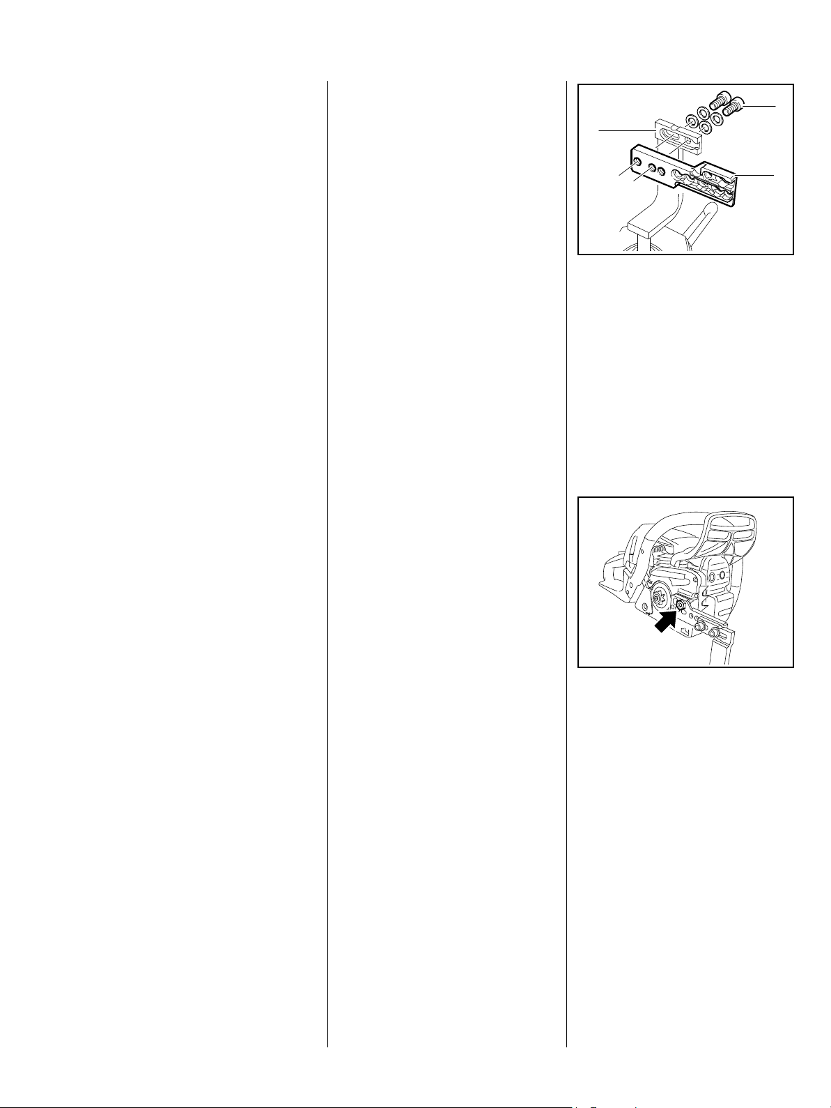
Servicing and repairs are made
considerably easier if the machine
is mounted on assembly stand (3)
5910 890 3101. For this purpose,
secure the clamp (2)
5910 850 1650 to the assembly
stand with two screws (1).
The screws must not protrude, as
they may damage the housings
when clamping the machine,
depending on the machine.
Refer to the "Technical Information"
bulletins for engineering changes
which have been introduced since
publication of this Service Manual.
Technical information bulletins also
supplement the spare parts list and
Service Manual until an updated
edition is issued.
a Direction of
movement (long arrow)
@ 4.2 Reference to another
chapter, in this case to
Chapter 4.2
Service Manuals and technical
information bulletins are intended
exclusively for the use of properly
equipped repair shops. They must
not be passed on to third parties.
2410RA000 TG
The machine is guided with the
collar screw through the upper hole
of the clamping rail and fastened
using nut M 8 (arrow).
The machine is fastened to the
mount on the clamping rail by the
screw head on the crankcase.
3MS 241 C
Preparing to make repairs
Before repair tasks or clamping on
the assembly stand, always remove
the chain sprocket cover, saw chain
and guide bar.
Always use original STIHL
replacement parts.
They can be identified by the STIHL
part number
the logo {
and the
STIHL parts symbol K
The symbol may appear alone on
small parts.
Storage or disposal of oil and fuel
Collect fuel or lubricating oil in
a clean container and dispose of it
in accordance with environmental
regulations.
Plug connections on electrical
leads
a
1.2 Safety precautions
Specific national safety regulations
and the safety instructions in the
instruction manual must be
observed if the machine has to be
started up during maintenance or
repair work.
Gasoline is highly inflammable and
can also be explosive under certain
conditions.
Do not bring any fire, flame, spark or
other source of heat near the fuel.
All work with fuel must be performed
outdoors only. Spilled fuel must be
wiped away immediately.
Test for leakage after all work on the
fuel system and engine.
Exercise extreme caution while
carrying out maintenance and repair
work on the ignition system. The
high voltages which occur can
cause serious or fatal accidents.
Suitable gloves must be worn
without fail if parts are heated for
assembly/disassembly purposes.
Improper handling may result in
burns and other serious injuries.
The chapter "Tightening Torques"
lists all components of this machine
that must be tightened with the
specified tightening torques or
coated with thread-locking
adhesive. These specifications
must be observed throughout the
Service Manual when tightening
screws and nuts as well as other
fasteners.
Fuel system – barbed connectors
Pull or push the fuel hoses, by hand
whenever possible, in the direction
of the connector in order to ensure
leakproofness of the fuel system.
Avoid damaging the barbed
connectors
– sharp-edged pliers, screwdrivers,
etc., may not be used.
Also, do not cut open fuel hoses
with a knife or similar aids.
Do not reuse fuel hoses after
disassembly, but instead always
replace them with new hoses
– fuel hoses can be overstretched
when being detached.
Mount new fuel hoses dry or using
STIHL press fluid, b 16.
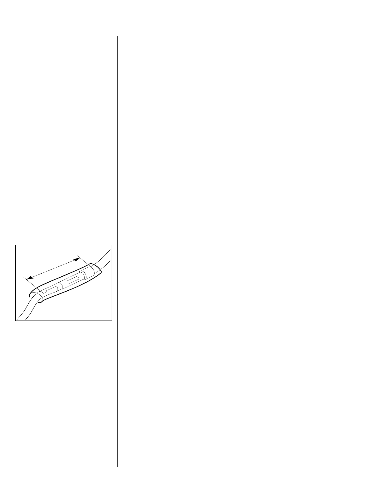
The insulating tube must be
oriented so that it is centered over
the plug connection and completely
enclose the plug connection
– danger of short-circuiting.
The plug connection is completely
plugged together when it has a total
length of a = max. 30 mm.
Always replace damaged parts.
Check dismantled parts for wear
and damage before installation,
replace if necessary.
5902RA299 TG
Only use the machine with the
shroud mounted – otherwise the
rotating fan wheel poses a risk of
injury and there is a risk of engine
damage due to overheating.
Other press fluids are not permitted
and may lead to fuel hose damage.
When using STIHL press fluid,
apply press fluid to the ends of the
hose and the connectors and press
the new hoses onto the barbed
connectors, b 16.
4 MS 241 C

2. Specifications
2.1 Engine
MS 241 C
Displacement: 42.6 cm
3
Bore: 42.5 mm
Stroke: 30.0 mm
Engine power to ISO 7293: 2.2 kW (3.0 HP)
at 10000 rpm
Max. permissible engine speed
(with bar and chain): 14000 rpm
Idle speed: 2800 rpm
Clutch: Centrifugal clutch without
linings
Clutch engages at: 3500 rpm
Crankcase leakage test
at gauge pressure: p
under vacuum p
= 0.5 bar
ü
= 0.5 bar
u
2.2 Fuel system
Carburetor leakage test at
gauge pressure: p
Operation of tank vent at
gauge pressure: p
Fuel: as specified in instruction
= 0.8 bar
ü
= 0.5 bar
ü
manual
2.3 Ignition system
2.4 Chain lubrication
Air gap between control unit
and fanwheel: 0.30 (+ 0.05/- 0.10) mm
Spark plug (suppressed): NGK CMR 6 H
Electrode gap: 0.5 mm
Speed-controlled oil pump with reciprocating piston and
manual oil flow control
Oil flow settings:
min:
4.0 (+/- 2.0) cm
3
/min
at 7000 rpm
max:
8.0 (+/- 3.0) cm
3
/min
at 7000 rpm
5MS 241 C

2.5 Tightening torques
DG and P screws are fitted in plastic and light alloy metal parts. These screws form a permanent thread when
they are installed for the first time. The material is permanently deformed. Screws can be removed and installed
as often as necessary without impairing the strength of the screwed assembly, provided that the specified
tightening torque is observed.
For this reason it is essential to use a torque wrench.
Fastener Thread size For component Tightening
torque
Nm
Screw P 4x12 Cover plate / fan housing 2.0
Screw P 4x10 Cover / tank housing 1.0
Screw D 4x12 Cover / chain tensioner / crankcase 2.5 2), 4)
Screw M 5x16 Antivibration element / crankcase 8.0 2), 4)
Screw P 5x34 Antivibration element / tank housing 4.0
Screw D 4x12 Brake band / crankcase 3.0 2), 4)
Screw P 4x10 Brake cable support / tank housing 1.0 Q
Stud M 5x18 Stud 7.0 2), 3)
Stud M 8 Bar mounting stud 23.0 1)
Stud M 8 Bar mounting stud 23.0 1), B
Stud D 8x18 Bar mounting stud (repair solution) 16.0
Screw D 4x12 Cover, chain brake / crankcase 3.0 2), 4)
M 10x1 Decompression valve 14.0
Nut M 5 Filter base / baffle / carburetor 3.5
Screw M 4x12 Generator / crankcase 3.0 3), VW
Screw P 6x25 Handlebar / locking screw 8.0 VW
Screw P 6x26.5 Handlebar / tank housing right 6.0
Screw P 6x30 Handlebar / tank housing right 6.0 2), 4), VW
Screw M 5x16 Handlebar / tank housing bottom 5.0 2), 3)
Screw M 5x12 Handlebar / tank housing bottom 8.0 3), VW
Screw M 5x16 Handlebar / plugs antivibration springs 10.0 2), 3), VW
Screw M 5x20 Hand guard / fan housing / crankcase 6.0 3)
Screw P 6x30 Chain catcher / crankcase / bearing plugs 6.0
Nut M 5 Spiked bumper / crankcase / upper lock nut 8.0
Screw M 5x10 Spiked bumper / top of crankcase 8.0 2), 3)
Screw M 5x16 Spiked bumper / bottom of crankcase 8.0 2), 3)
Screw D 4x12 Manifold / cylinder 4.0 2), 4)
Screw M 5x20 Crankcase drive side / fan side 10.0 2), 4)
Screw M 5x16 Bearing plugs / cylinder 10.0 2), 3)
Screw M 5x16 Fan housing / crankcase 6.0 2), 4)
Screw D 4x12 Air guide shroud / crankcase 4.0 2), 4)
Comment
6 MS 241 C

Fastener Thread size For component Tightening
torque
Nm
Carrier M 12x1 L Crankshaft carrier 50.0
Screw D 4x12 Oil pump / crankcase 4.0 2), 4)
Screw M 5x16 Muffler / crankcase 10.0 2), 3)
Screw M 5x16 Muffler / cylinder 10.0 2), 3)
Nut M 8x1 Flywheel / crankshaft 28.0 5)
Nut M 12x0.75 Switch 2.0
Screw P 4x10 Support 1.0
Screw D 4x12 Pre-separator / crankcase 4.0 2), 4)
M 10x1 Spark plug / cylinder 12.0
Screw D 4x20 Control unit / cylinder 4.5 2), 4)
Screw M 5x20 Cylinder / crankcase 1st stage 4.0 2), 4)
Screw M 5x20 Cylinder / crankcase 2nd stage 10.0 2), 4)
Remarks:
1) Loctite 242 or 243 medium strength
2) Screws with locking serration
3) Microencapsulated screws
4) Screws with easy-slide coating
5) Connection between crankshaft and flywheel must be degreased and oil-free
Q) QuickStop Super
B) Quick chain tensioner
VW) Heating
Comment
When inserting DG and P screws into an existing screw thread:
Insert the DG or P screw in the hole and turn counterclockwise until it gently drops into the hole in axial direction.
Tighten the screw clockwise to the specified torque.
This procedure ensures that the screw engages properly in the existing thread and does not form a new thread
and weaken the assembly.
Coat micro-encapsulated screws with Loctite 242 or 243 medium strength before refitting them.
Screwdriver speed when used in plastic material: max. 500 rpm for DG and P-type screws.
Do not use an impact wrench to release or tighten screw connections.
Screws with and without locking serration must not be confused.
7MS 241 C

3. Troubleshooting
3.1 Clutch
Problem Cause Remedy
Saw chain becomes stuck under
full load
Saw chain rotates at idle speed Idle speed too high Check M-Tronic
Loud noises Tension springs stretched Replace all tension springs
Clutch shoes badly worn Install new clutch
Clutch drum badly worn Install new clutch drum
Tension springs of the clutch shoes
are stretched
Tension springs of the clutch shoes
are broken
Needle cage damaged Replace needle cage
Clutch shoe retainer broken Examine retainer, replace if
Replace tension springs, replace
clutch if necessary
Replace tension springs
necessary
Clutch shoes and carrier worn Install new clutch
8 MS 241 C

3.2 Chain Drive, Chain Brake, Chain Tensioner
Problem Cause Remedy
Chain sprocket wears rapidly Chain not properly tensioned Tension chain as specified
Wrong chain pitch Fit chain of correct pitch
Insufficient chain lubrication Check chain lubrication
Saw chain becomes stuck under
full load
Saw chain rotates at idle speed Idle speed too high Check M-Tronic
Saw chain does not stop
immediately when brake is
activated
Clutch shoes badly worn Install new clutch
Clutch drum badly worn Install new clutch drum
Brake band stuck Check freedom of movement and
function of brake band
Tension springs of the clutch shoes
are stretched
Tension springs of the clutch shoes
are broken
Brake spring stretched or broken Fit new brake spring
Replace tension springs, replace
clutch if necessary
Replace tension springs
Brake band stretched, worn or
broken
Clutch drum worn Install new clutch drum
Fit new brake band
9MS 241 C

Problem Cause Remedy
QuickStop Super
Coasting brake is not released
although trigger interlock is pressed
QuickStop Super
Brake band is not released
although trigger interlock is pressed
QuickStop Super
Coasting brake does not brake
properly – trigger interlock not
pressed
Brake cable stretched Adjust brake cable
Brake cable unhooked or broken Reattach or replace brake cable
Excessive play on trigger interlock Adjust brake cable
Brake cable overstretched Adjust brake cable
Sleeve of the brake cable not
seated completely in adjusting
screw
Push the sleeve into the adjusting
screw as far as it will go and adjust
brake cable
10 MS 241 C

3.3 Chain lubrication
In the event of trouble with the
chain lubrication system, check and
rectify other sources of faults
before disassembling the oil pump.
Problem Cause Remedy
Chain receives no oil Oil inlet hole in guide bar is blocked Clean oil inlet hole
.
Intake hose or pick-up body
clogged or intake hose ruptured
Valve in oil tank blocked Clean or replace valve
Worm worn Replace worm
Oil pump damaged or worn Install new oil pump
Machine looses chain oil Oil pump damaged or worn Install new oil pump
Oil intake hose connection
damaged
Crankcase cracked Check crankcase halves and
Oil pump delivers insufficient oil Oil pump damaged or worn Install new oil pump
Worm carrier is loose Replace worm
Fit new intake hose and pick-up
body
Fit new oil intake hose
replace damaged crankcase halves
11MS 241 C

3.4 Starter
Problem Cause Remedy
Starter rope broken Rope pulled out too vigorously as
far as stop or over edge, i.e. not
vertically
Normal wear Replace starter rope
Starter rope does not rewind Heavy fouling or rust on rewind
spring
Spring insufficiently tensioned Check rewind spring and increase
Rewind spring broken Replace rewind spring
Starter rope cannot be pulled out
far enough
Starter rope can be pulled out
almost without
resistance (crankshaft does not
turn)
Rewind spring overtensioned Check rewind spring and reduce
Guide peg on pawls or pawls
themselves are worn
Replace starter rope
Clean or replace rewind spring
tension
tension
Replace pawls
Spring clip fatigued Replace spring clip
Spring clip improperly installed Install spring clip properly
...Versions with ErgoStart Guide peg on pawls or pawls
themselves are worn
Torsion spring on flywheel are
fatigued, pawls are worn or sticking
Lugs on carrier are worn Replace carrier
Anchor loop in spring housing not
hooked onto carrier
Starter rope is difficult to pull –
versions with ErgoStart
Spring in spring housing is fatigued Replace spring housing
Replace pawls
Clean mounts on the pawls,
replace pawls and torsion springs if
necessary
Hook anchor loop to carrier
12 MS 241 C

Problem Cause Remedy
Starter rope is difficult to pull or
rewinds very slowly
Starter mechanism is very dirty Thoroughly clean complete starter
mechanism
At very low outside temperatures:
Lubricant oil on the rewind spring
becomes viscous (spring winding
stick together) or moisture has
penetrated the rewind spring
(spring windings are frozen)
Coat rewind spring with a little
standard solvent-based degreasant
(containing no chlorinated or
halogenated hydrocarbons), then
pull rope carefully several times
until normal action is restored
13MS 241 C

3.5 Ignition system
Problem Cause Remedy
Engine runs roughly, misfires,
temporary loss of power
Spark plug boot is loose Press boot firmly onto spark plug
and fit new spring if necessary
Spark plug sooted, smeared with oil Clean the spark plug or replace if
necessary
In the event of repeated sooting,
check air filter
Fuel/oil mixture
– contains too much oil
Wrong air gap between control unit
and flywheel
Flywheel is cracked
or has other damage or pole shoes
have turned blue
Incorrect ignition timing, flywheel
out of adjustment
– Key in flywheel has sheared off
Weak magnetization in flywheel Install new flywheel
Use a fuel mixture with the correct
mixing ratio
Set the correct air gap
Install new flywheel
Install new flywheel
Irregular spark Check operation of switch shaft/
contact spring and control unit
Damaged insulation or interruption
in ignition lead or short circuit wire.
Check ignition lead/control unit,
replace control unit if necessary.
Check operation of spark plug,
clean spark plug and replace if
necessary. Check M-Tronic
14 MS 241 C

3.6 Carburetor
Problem Cause Remedy
Carburetor floods; engine stalls Inlet needle not sealing
– Foreign matter in valve seat or
cone
Inlet needle worn Replace inlet needle
Inlet control lever sticking on
spindle
Helical spring not located on nipple
of inlet control lever
Perforated disc on diaphragm is
deformed and presses constantly
against the inlet control lever
Metering diaphragm is deformed Replace metering diaphragm
Poor acceleration Carburetor setting too lean Check M-Tronic
Carburetor setting too rich Check M-Tronic
Remove and clean inlet needle or
clean carburetor
Examine control lever, replace if
necessary
Remove the inlet control lever and
refit it correctly
Replace metering diaphragm
Inlet needle sticking to valve seat Remove inlet needle, clean and
refit
Diaphragm gasket leaking Replace diaphragm gasket
Metering diaphragm damaged or
shrunk
Tank vent faulty Replace tank vent
Leak in fuel line between tank and
carburetor
Replace metering diaphragm
Seal connections or replace line
15MS 241 C

Problem Cause Remedy
Engine will not idle, idle speed too
high
Engine stops when idling Idle jet bores
Throttle shutter is not closed
properly when the throttle trigger is
not pressed
Oil seals or crankcase leaking Seal oil seals or crankcase, replace
Throttle shutter does not close Replace carburetor
or ports blocked
Idle jet too rich or
too lean
Tank vent faulty Replace tank vent
Leak in fuel line between tank and
carburetor
Examine carburetor and throttle
rod, replace if necessary
if necessary
Clean the carburetor
Check M-Tronic
Seal connections or replace line
Saw chain rotates at idle speed Idle speed too high Check M-Tronic
Clutch springs stretched or fatigued Replace tension springs, replace
clutch if necessary
Anchor loops of the clutch spring
hooks are broken
Replace tension springs
16 MS 241 C

Problem Cause Remedy
Engine speed drops quickly under
load – low power
Air filter dirty Clean air filter, replace if necessary
Throttle shutter not opened fully Check throttle rod
Tank vent faulty Replace tank vent
Fuel pick-up body dirty Replace pickup body
Fuel strainer dirty Clean fuel strainer in carburetor,
replace if necessary
Leak in fuel line between tank and
carburetor
Carburetor setting too lean Check M-Tronic
Main jet bores or ports blocked Clean the carburetor
Pump diaphragm damaged or
fatigued
Seal connections or replace line
Replace pump diaphragm
Engine runs extremely rich, lacks
power and has very low final speed
Incorrect ignition timing, flywheel
out of adjustment
– Key in flywheel has sheared off
Choke shutter does not open Examine the carburetor and starter
Carburetor setting too rich Check M-Tronic
Install new flywheel
shaft and repair or replace if
necessary
17MS 241 C

3.7 Engine
Always check and, if necessary,
repair the following parts before
looking for faults on the engine:
- Air filter,
- Fuel system,
- Carburetor,
- Ignition system
Problem Cause Remedy
Engine does not start easily, stalls
at idle speed but operates normally
at full throttle
Engine does not deliver full power
or runs erratically
Oil seals in engine defective Replace oil seals
Crankcase leaking or
damaged (cracks)
Intake manifold damaged/ hole is
plugged
Piston rings worn or broken Replace piston rings
Muffler / spark arresting screen
carbonized
Air filter dirty Clean or replace air filter
Fuel line kinked or cracked Replace fuel line and ensure that is
Replace damaged crankcase
halves
Clean hole or replace intake
manifold
Clean muffler (inlet and outlet
openings), replace spark arresting
screen, replace muffler if necessary
installed without kinking
Intake manifold damaged / hole is
plugged
Engine is overheated Insufficient cylinder cooling. Air
inlets in fan housing blocked or
cooling fins on cylinder very dirty
Air intake in fan housing is fouled Clean air intake on fan housing
18 MS 241 C
Clean hole or replace intake
manifold
Thoroughly clean all cooling air
openings and the cylinder fins
4. Clutch
4.1 Clutch drum
– Clutch drum removal and
installation, see Instruction
Manual
– Remove needle cage
– Clean needle cage and
crankshaft stub, b 16
– Grease needle cage and
crankshaft stub, b 16
100%
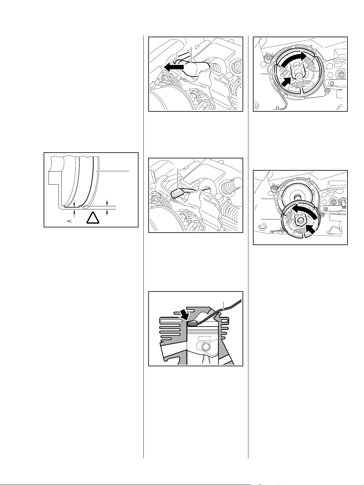
1
: Remove the spark plug boot (1)
– Unscrew spark plug
1
1
1
2410RA001 TG
: Unscrew the clutch (1) with
hexagon (arrow) – left-hand
thread
Installation
TOP
1
2410RA004 TG
80%
!
– Examine the clutch drum (1) for
signs of wear
The remaining thickness must be
measured if there are distinct signs
of wear on the inside diameter of the
clutch drum (1). The clutch drum
must be replaced if the remaining
thickness is less than approx. 80 %
of the original thickness.
– Install the clutch drum
4.2 Clutch
– Troubleshooting, b 3.1
– Removing the clutch drum,
b 4.1
– Remove shroud, b 6.4
5902RA018 TG
: Orient the locking strip (1)
0000 893 5904 so that the flat
side of the metallic attachment
faces the piston and insert it in
the cylinder
: Locking strip (1) 0000 893 5904
must rest against the cylinder
wall (arrow) and the flat side of
the metal attachment must rest
against the piston head
– Position as shown
2
2410RA002 TG
2410RA005 TG
Slide washer (1) into place so that
the word "TOP" is visible.
: Fit the clutch (2) on the
crankshaft stub so that the raised
hexagon (arrow) can be seen
1
: Screw on and tighten the
clutch (2) – left-handed thread
– Pull the locking strip out of the
cylinder
– Reassemble remaining parts in
2410RA003 TG
reverse order
19MS 241 C
5. Chain brake
5.1 Checking operation of chain brake
The chain brake is one of the most
important safety devices on the
chain saw. Its efficiency is
measured in terms of the chain
braking time, i.e., the time that
elapses between activating the
brake and the saw chain coming to
a complete standstill.
Fouling (particularly with chain oil,
chips, fine particles of abrasion,
etc.) and smoothing of the friction
surfaces of the brake band and
clutch drum impair the coefficient of
friction. This in turn extends the
braking time. A fatigued or stretched
brake spring has the same negative
effect.
– Starting the engine
– With the chain brake
activated (locked), open the
throttle wide for a brief
period (max. 3 seconds) – the
chain must not rotate
– With the chain brake released,
open the throttle wide and
activate the brake manually – the
chain must come to an abrupt
stop
Versions with QuickStop Super
When the trigger interlock is
pressed, the clutch drum must
rotate freely.
With the coasting brake released,
open the throttle wide and release
the trigger interlock in the rear
handle – the saw chain must come
to an abrupt stop
All versions
The braking time is in order if
deceleration of the saw chain is
imperceptible to the eye (less than 1
second).
If the chain brake does not operate
properly, refer to the
troubleshooting chart, b 3.2.
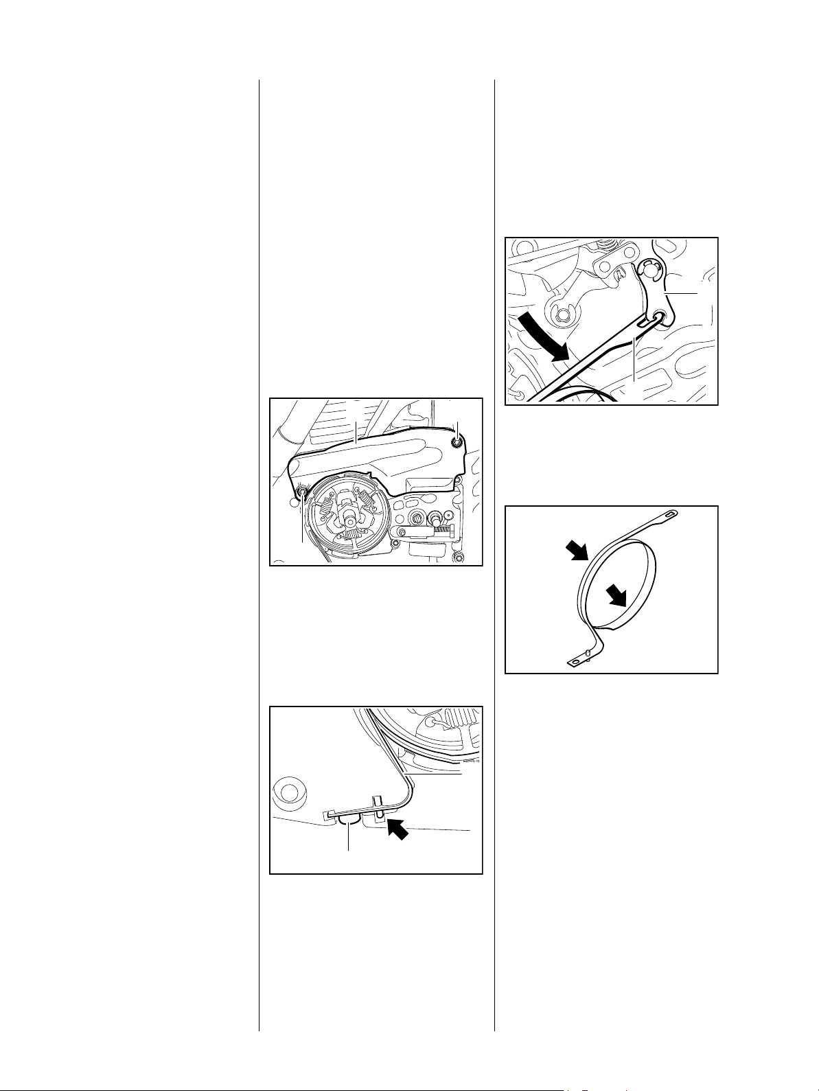
5.2 Brake band
– Remove the clutch drum, b 4.1
– Troubleshooting, b 3.2
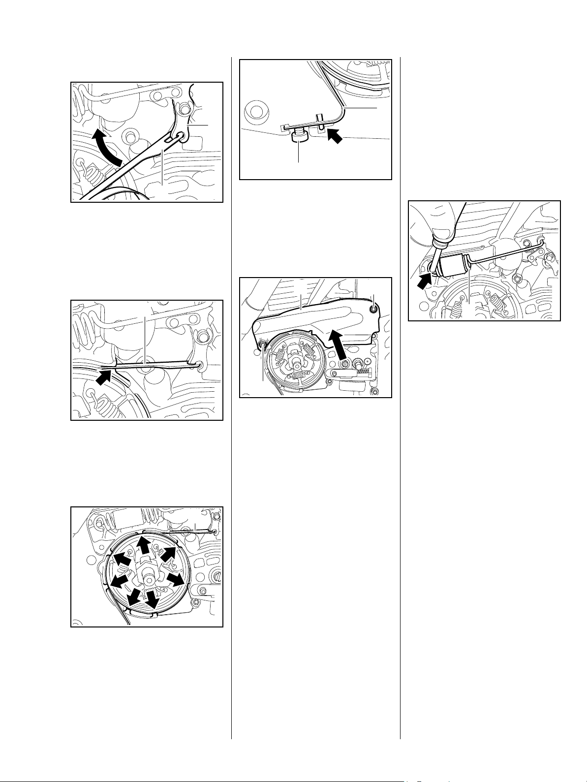
12
1
: Remove screws (1)
: Remove the cover (2)
– Block chain brake
2
: Ease brake band (2) out of
guide (arrow)
– Remove brake band, taking care
not to overextend it
– Release the chain brake
1
: Turn brake band (1) slightly aside
and disconnect it from the brake
lever (2)
2410RA006 TG
Install a new brake band if there are
noticeable signs of wear on large
areas on the inside diameter and/or
parts of the outside (arrows) and its
remaining thickness is less than
< 0.6 mm.
2
5902RA024 TG
219RA049 TG
1
2410RA007 TG
: Unscrew screw (1) on the bottom
of the machine
20 MS 241 C
Installation
5.3 Brake lever
– Troubleshooting, b 3.2
1
– Remove shroud, b 6.4
2
– Remove fan housing, b 9.2
1
– Release the chain brake
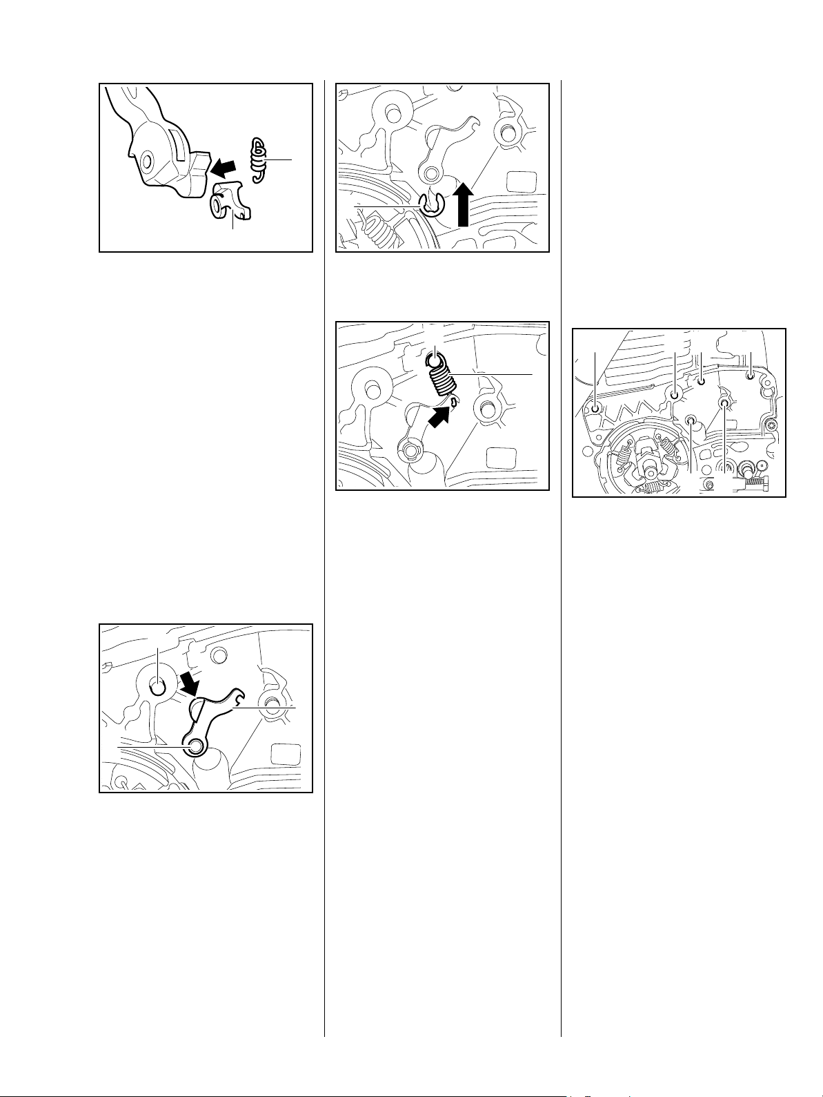
: Attach brake band (1) to brake
lever (2) sideways and turn it
towards its mount
1
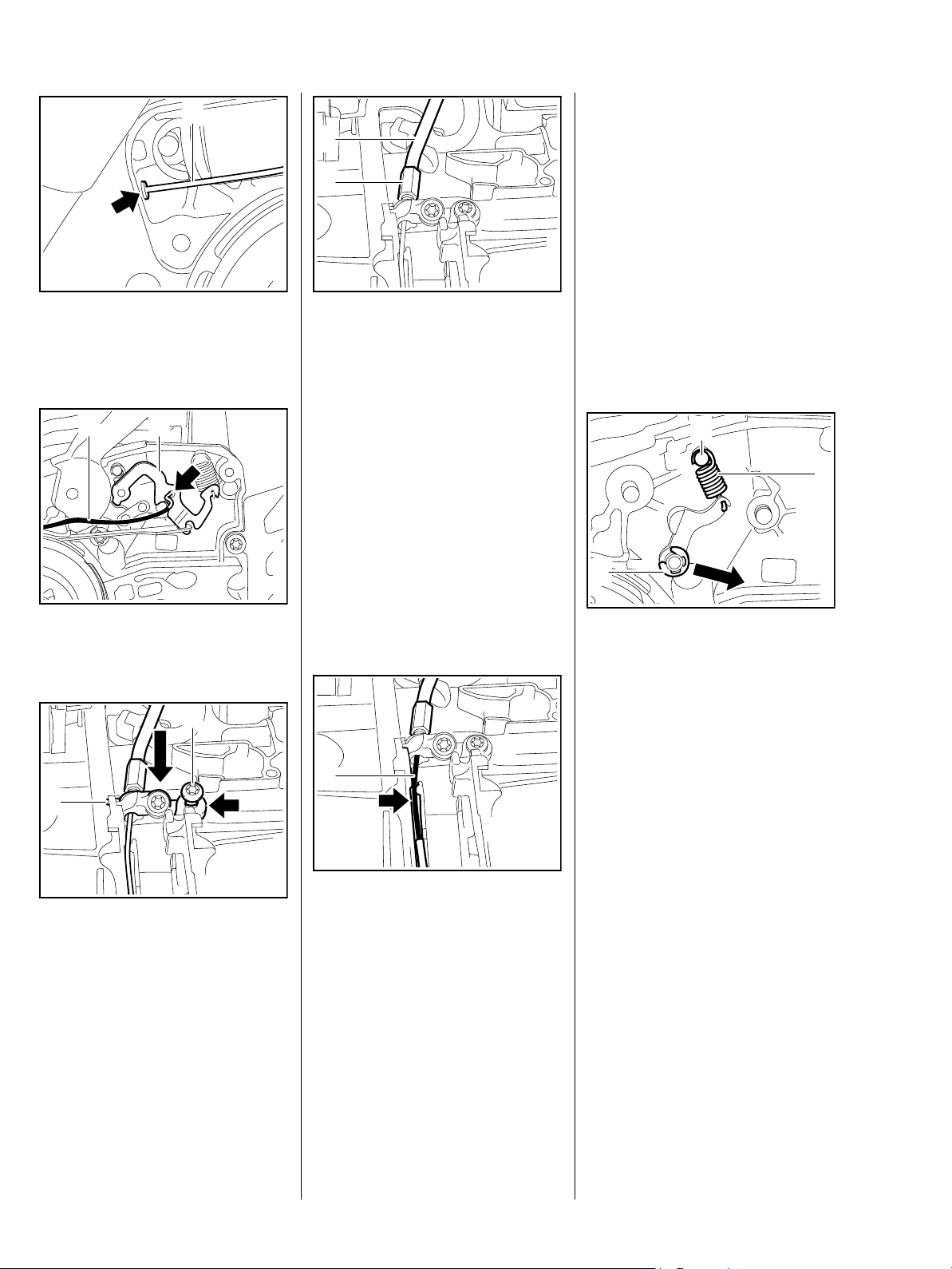
: Insert brake cable (1) in
guide (arrow)
2
: Push brake band (1) fully home in
2410RA009 TG
the mount (arrow)
: Screw in and tighten screw (2) on
the bottom of the machine
2
: Insert cover (1)
2410RA010 TG
: Insert and tighten down the
screws (2)
21
– Remove brake band, b 5.2
2410RA012 TG
1
– Block chain brake
The brake spring is now relaxed.
: Use the assembly tool
2410RA013 TG
1117 890 0900 to unhook the
brake spring (1) at the anchor
pin (arrow)
– Unhook and remove the brake
spring at the brake lever
2410RA014 TG
– Block chain brake
1
: Guide brake band (1) over
studs (arrows) and press it into
the mount
– Install the clutch drum, b 4.1
When the chain brake is released,
the clutch drum must rotate freely.
– Carry out additional function
tests, b 5.1
– Reassemble remaining parts in
reverse order
2410RA011 TG
21MS 241 C
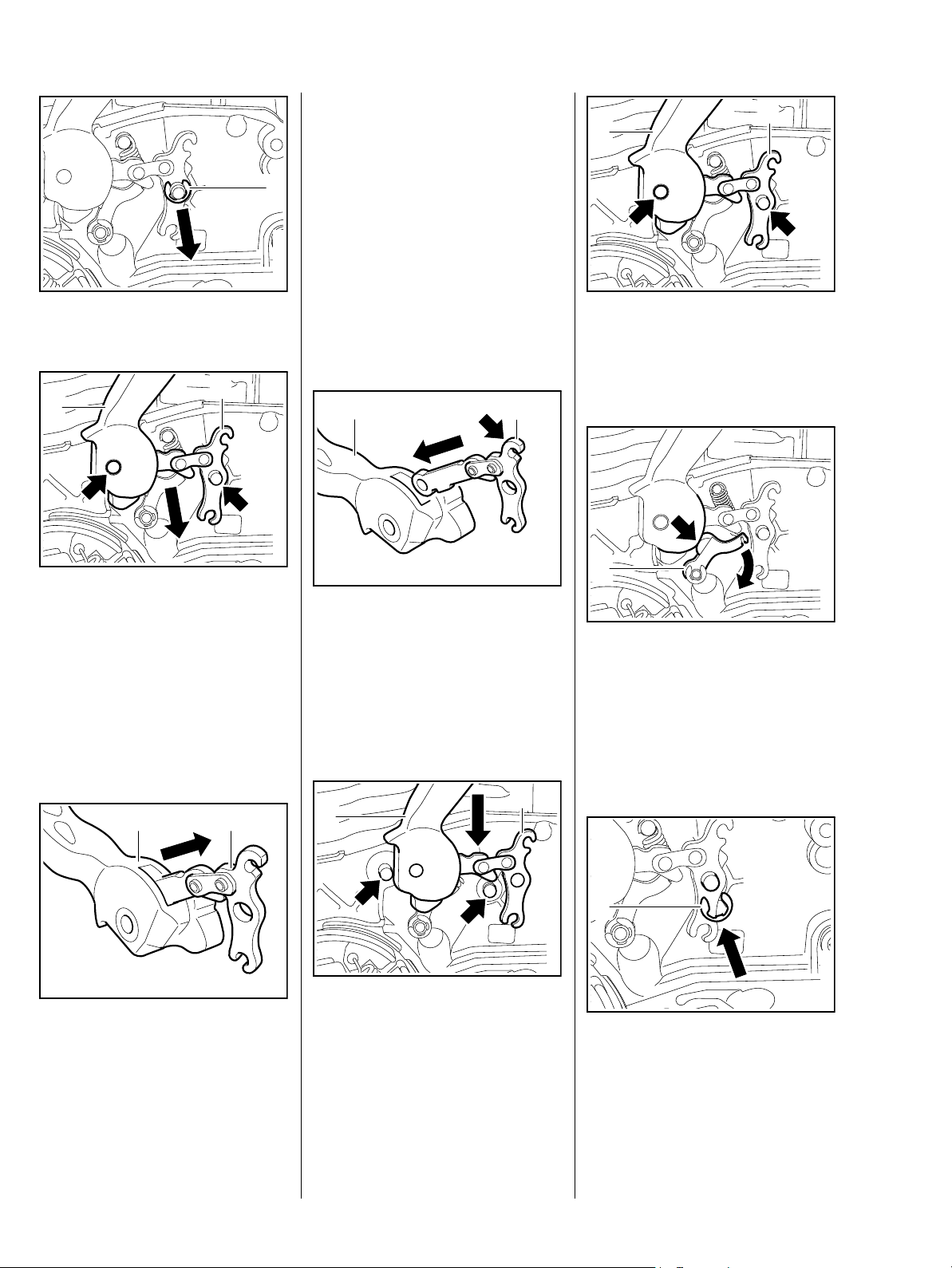
: Push out circlip (1)
1
– Examine pins and replace if
necessary, b 5.6
2
1
– Check cam on hand guard,
1
replace hand guard if necessary
Installation
– Clean pins and disassembled
2410RA015 TG
parts, b 16
2410RA020 TG
: Slightly lift up bearing eye of the
– Grease pins, b 16
hand guard (1) and brake
lever (2) and guide the parts over
the anchor pins (arrows)
2
1
2
: Draw hand guard (1) and brake
lever (2) off the anchor
pins (arrows) simultaneously
– Take out hand guard and brake
lever
– Examine cam lever and replace if
necessary, b 5.5
21
: Pull brake lever (2) out of hand
guard (1)
2410RA016 TG
: Position brake lever (2) so that
mount for brake spring (arrow) is
at the top
: Slide brake lever (2) into recess
in hand guard (1) until the holes
are lined up
1
2410RA017 TG
: Slide hand guard (1) with brake
lever (2) across the machine until
it rests against the anchor
pins (arrows)
2
1
2410RA018 TG
: Turn cam lever (1) slightly aside
until cam of hand guard (arrow)
slides past
– Press bearing eye of hand guard
and brake lever onto the anchor
pins
1
2410RA019 TG
: Push circlip (1) into place
2410RA021 TG
2410RA022 TG
22 MS 241 C
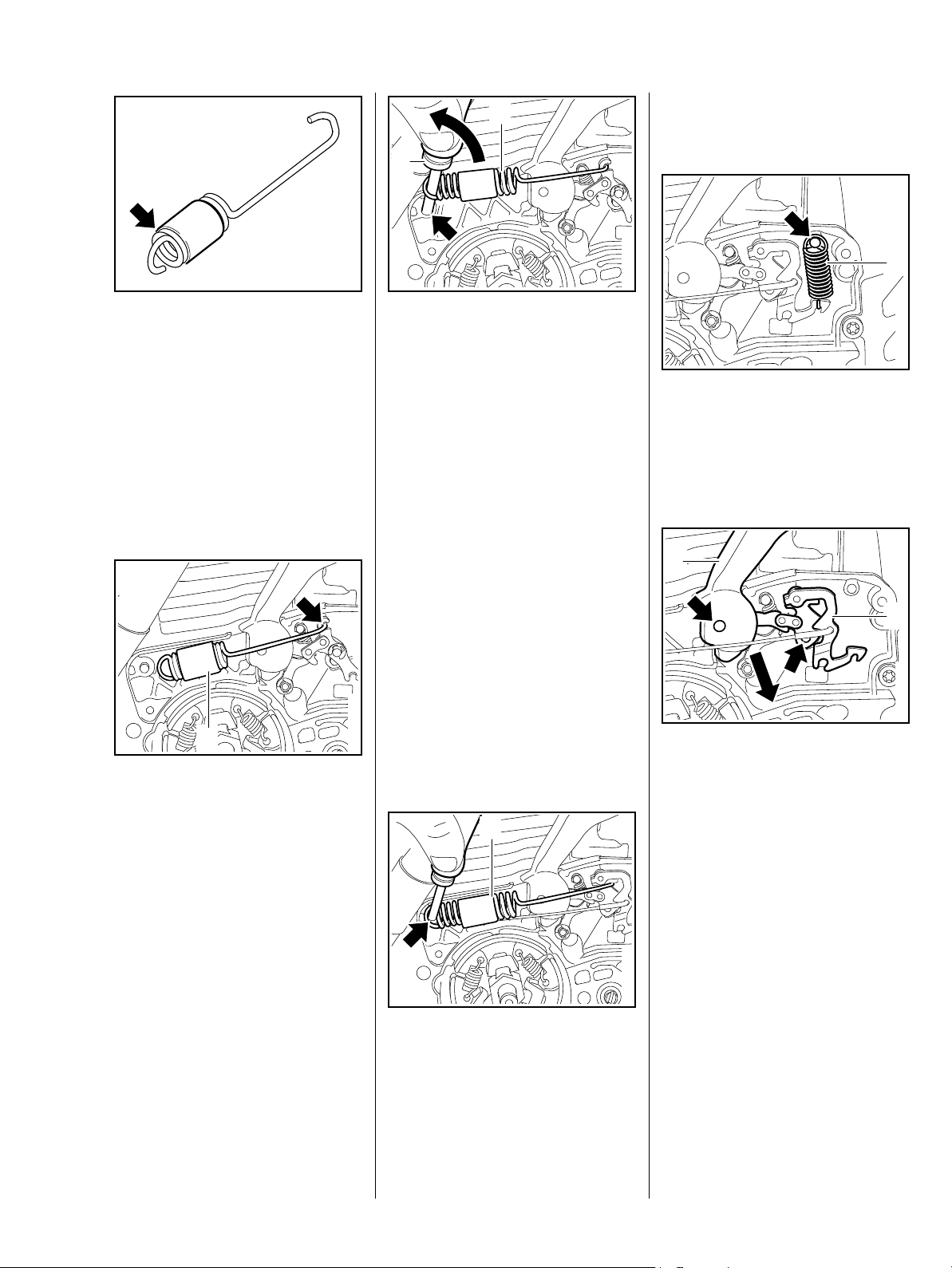
2
5902RA040 TG2410RA023 TG
1
spring at the brake lever
1
2410RA024 TG
– Unhook and remove the brake
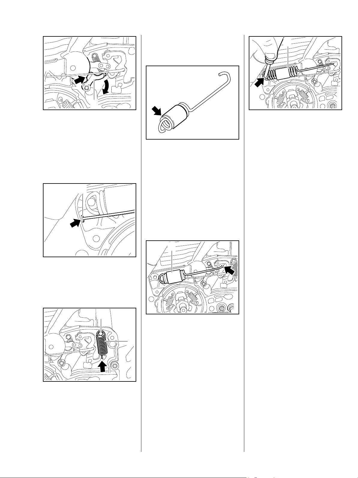
The turns of the brake spring must
be tightly spaced when not installed;
use a new brake spring if necessary.
– Position the protective tube so
that it starts after the
second turn (arrow)
– The pin for the brake spring must
be replaced if it shows signs of
wear at the groove, b 5.6
1
: Hook brake spring (1) into brake
lever (arrow)
: Use the assembly tool (2)
1117 890 0900 to attach the
brake spring (1) to the anchor
pin (arrow)
– Grease brake lever, cam lever
and hand guard motion link,
b 16
– Reassemble remaining parts in
reverse order
5.4 QuickStop Super brake lever
– Troubleshooting, b 3.2
– Remove shroud, b 6.4
– Remove fan housing, b 9.2
– Remove brake band, b 5.2
2410RA026 TG
: Unhook brake spring (1) from
anchor pin (arrow)
: Unhook and remove the brake
spring (1) at the brake lever
1
2
2410RA027 TG
: Draw hand guard (1) and brake
lever (2) off the anchor
pins (arrows) simultaneously
1
– Block chain brake
The brake spring is now relaxed.
: Use the assembly tool
1117 890 0900 to unhook the
brake spring (1) at the anchor
pin (arrow)
– Take out hand guard and brake
lever
2410RA025 TG
23MS 241 C
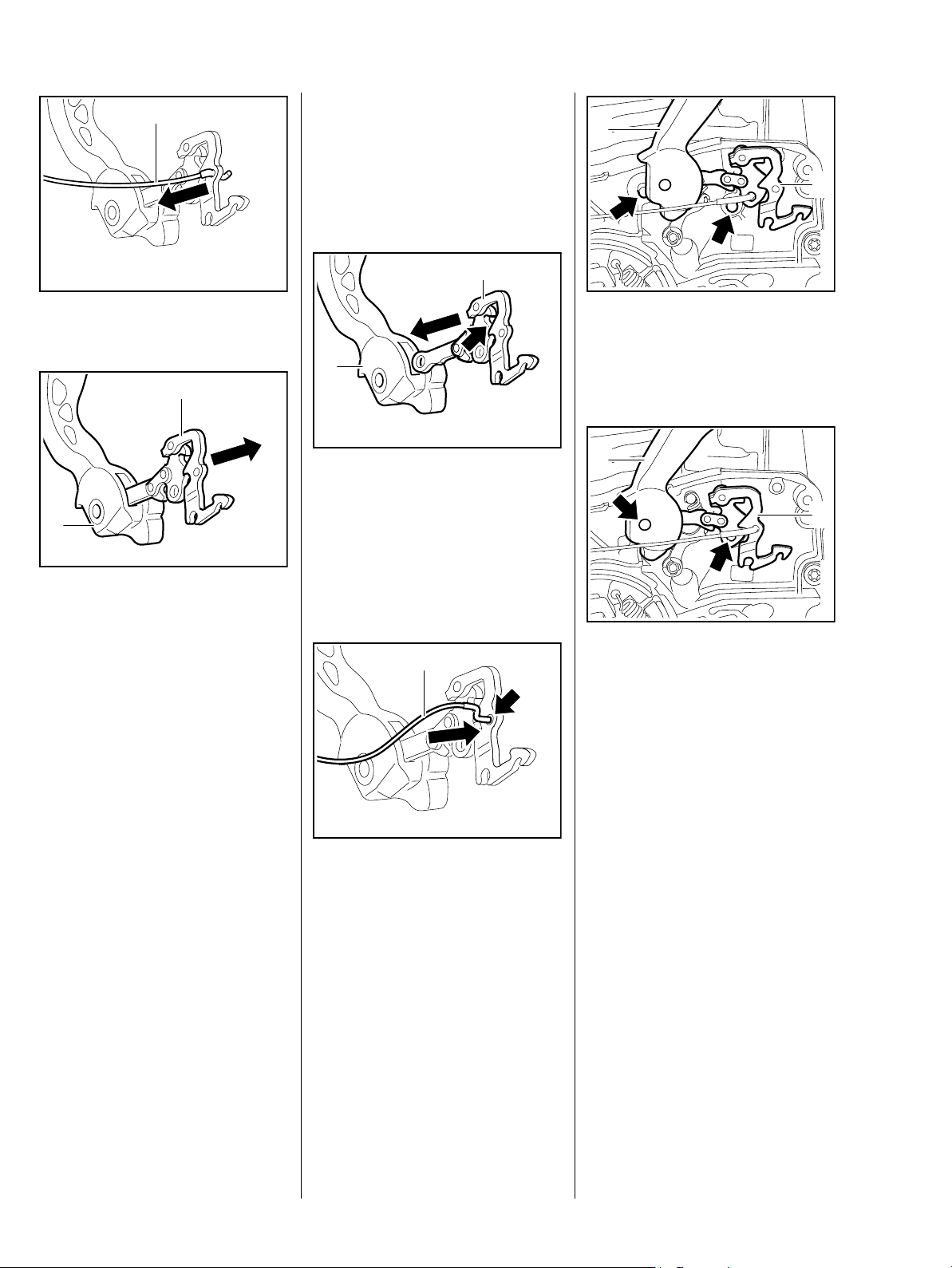
1
Installation
– Clean pins and disassembled
parts, b 16
1
: Disconnect brake cable (1)
2
1
: Pull brake lever (2) out of hand
guard (1)
– Examine cam lever and replace if
necessary, b 5.5
– Examine pins and replace if
necessary, b 5.6
– Grease pins, b 16
2410RA028 TG
2
1
: Position brake lever (2) so that
mount for brake spring (arrow) is
at the top
: Slide brake lever (2) into recess
2410RA029 TG
in hand guard (1) until the holes
are lined up
1
2
2410RA032 TG
: Slide hand guard (1) with brake
lever (2) across the machine until
it rests against the anchor
pins (arrows)
2410RA030 TG
1
2
2410RA033 TG
: Slightly lift up bearing eye of the
hand guard (1) and brake
lever (2)and guide the parts over
the anchor pins (arrows)
– Check cam on hand guard,
replace hand guard if necessary
2410RA031 TG
: Attach brake cable (1) to
hole (arrow) in brake lever
24 MS 241 C
: Attach brake spring (1) to anchor
pin (2)
1
1
: Turn cam lever (1) aside until
cam of hand guard (arrow) slides
past
– Press bearing eye of hand guard
and brake lever onto the anchor
pins
1
: Check seat of the sleeve (1) at
the brake cable, push completely
into the hole in the
housing (arrow) if necessary
2410RA034 TG2410RA035 TG
The turns of the brake spring must
be tightly spaced when not installed;
use a new brake spring if necessary.
– Position the protective tube so
that it starts after the
second turn (arrow)
– The pin for the brake spring must
be replaced if it shows signs of
wear at the groove, b 5.6
1
: Use the assembly tool
1117 890 0900 to hook the brake
5902RA040 TG
spring (1) onto the anchor
pin (arrow)
– Grease brake lever, cam lever
and hand guard motion link,
b 16
– Adjust brake cable, b 5.4.1
– Reassemble remaining parts in
reverse order
5.4.1 Adjusting brake cable
If the coasting brake does not
operate properly although the brake
band is intact, it may be necessary
to adjust the brake cable.
– Troubleshooting, b 3.2
– Check condition and play
2410RA025 TG
2
: Hook brake spring (1) into the
brake lever so that the opening of
the anchor loop (arrow) is visible
: Hook brake spring (1) onto brake
lever (arrow)
1
2410RA036 TG
2410RA037 TG
– Remove chain brake cover,
b 5.2
When the trigger interlock is not
pressed, the brake cable must
be without tension.
25MS 241 C
Adjust brake cable
: Screw in adjusting screw (2)
– Play increases
1
– Press and hold the trigger
interlock down completely
Brake band (1) must rest against
the crankcase (arrows) without play
and the clutch drum must rotate
freely.
– Release trigger interlock
1
a
1
2
2410RA038 TG
: Remove screw (1)
: Lower tank housing (2)
: Unscrew adjusting screw (2)
– Play decreases
: Once play is adjusted correctly,
tighten clamping screw (3)
2410RA039 TG
1
1
– Press and hold the trigger
interlock down completely
Brake band (1) must rest against
the crankcase (arrows) without play
and the clutch drum must rotate
freely.
2310RA050 TG
2410RA038 TG
: Press trigger interlock (1) gently
to check the play
– The play must not exceed the
mark (a)
Play: is equal to the distance
traveled by the trigger interlock (1)
without causing the brake lever to
move at the same time.
Play is necessary to ensure trouble
free functioning of the coasting
brake.
– Troubleshooting, b 3.2
: Loosen clamping screw (1) on
the support for the brake cable
0001RA456 TG
1
2
The sleeve (1) must be seated on
the adjusting screw (2) as far as it
will go.
: Position open-end wrench SW 6
on the adjusting screw (2) and
adjust play
– Reassemble remaining parts in
reverse order
3
2410RA556 TG
26 MS 241 C
5.4.2 Brake cable Removal and installation
– Unhook brake spring, b 5.4
1
support (2) with a gentle twisting
motion
: Push hook (1) through the
– Remove QuickStop Super
throttle trigger, b 11. 3
– Remove QuickStop Super trigger
switch, b 11.3.1
1
: Pull brake cable (1) out slightly
and disconnect it
– Loosen tank housing and lower it,
b 13.11.2
– Do not overextend fuel hose
2
: Examine brake cable (1) and
support (2), replace if necessary
Dismantle brake cable and
support
1
2410RA040 TG
3 4
: Unscrew clamping screw (1) and
adjusting screw (2)
12
2310RA053 TG
2310RA056 TG
: Turn adjusting screw (1) until the
distance between the hexagon of
the adjusting screw and the
2
holder is 2 mm
: Screw in the clamping screw (2)
and tighten
4
2310RA054 TG
2
3
2
: Remove screw (1)
: Remove support (2) with brake
cable
: Turn hook (3) so that the angled
part is at the opening (arrow) and
twist it out of the support (4)
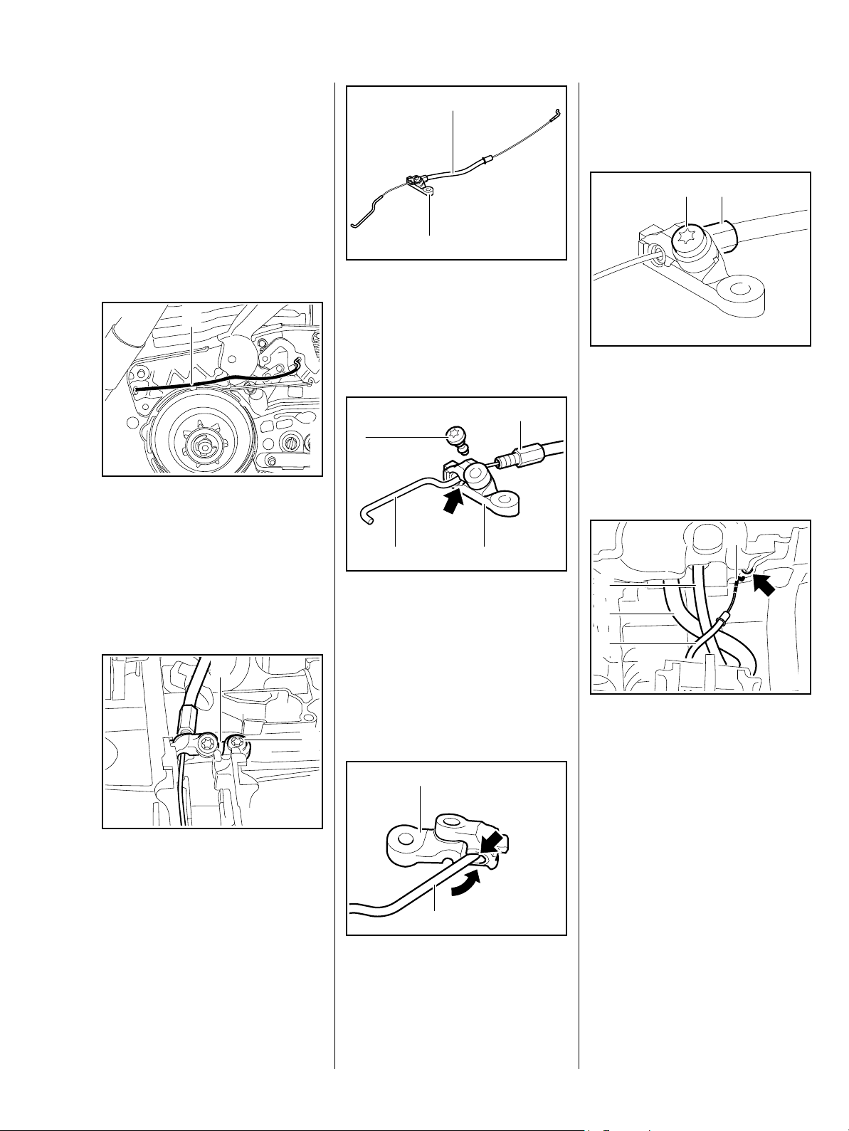
Installation
1
2
2410RA041 TG
1
: Turn hook (1) so that it runs along
the support (2) and push it into
the hole (arrow)
1
2410RA042 TG
: Guide the brake cable (1) over
fuel hose (3) or, in versions with
manual fuel pump, over the fuel
hose (3) and fuel return line (2)
: Push brake cable (1) with short
hook (4) in front through the
hole (arrow) in the crankcase
2310RA055 TG
27MS 241 C
1
reverse order
1
– Adjust brake cable and check
– Reassemble remaining parts in
2
operation, b 5.4.1
5.5 Cam lever
: Push brake cable (1) with sleeve
into the hole in the
housing (arrow) as far as it will go
1 2
: Hook brake cable (1) into
hole (arrow) in brake lever (2)
2
2410RA043 TG
When raising the tank housing,
make certain that the sleeve (1) is
pushed completely into the
adjusting screw (2) – incomplete
insertion of the sleeve changes the
setting of the brake cable.
– Check position of the fuel hose
and correct it if necessary,
b 13.11.2
– Check position of the fuel return
line and correct it if necessary,
b 13.11.3
2410RA044 TG
– Raise and fasten the
tank housing, b 13.11.2
2410RA046 TG
The cam lever defines the engaged
position of the hand guard.
– Remove brake lever, b 5.3,
QuickStop Super, b 5.4
2
3
: Unhook the brake spring (1) from
the anchor pin (2)
– Unhook and remove the brake
spring (1) at the cam lever
1
2410RA048 TG
1
: Press brake cable holder with the
pin (1) through the opening and
into the mount (arrow)
: Screw in the screw (2) and
tighten it
1
2410RA045 TG
: Insert brake cable (1) in
guide (arrow)
– Install QuickStop Super trigger
switch, b 11.3.1
– Install QuickStop Super throttle
trigger, b 11.3
: Push out circlip (3)
– Remove cam lever
2410RA047 TG
28 MS 241 C
5.6 Pins
The pins ensure that the springs are
securely mounted. They must
2
therefore be replaced when worn,
otherwise the springs may pop out.
1
: Examine cam lever (1) and brake
spring (2) and replace if
necessary
: Check condition of cam
guide (arrow) and replace hand
guard if necessary
– Examine all pins and replace if
necessary,
b 5.6
Installation
– Clean pins and disassembled
parts, b 16
– Grease pins, b 16
1
2410RA049 TG
: Push circlip (1) into place
2
: Hook brake spring (1) into the
brake lever so that the opening of
the anchor loop (arrow) is visible
: Hook brake spring (1) onto
pin (2)
The pins must be driven in square.
For reasons of simplicity, the parts
2410RA051 TG
connected to the pins have already
been removed in the following
illustrations.
132
1
2410RA052 TG
: Remove pins (1) through (6)
Item 6 is present only in the version
with QuickStop Super.
6
54
2410RA053 TG
3
1
2
: Orient cam lever (1) so that the
cam (arrow) faces the pin (3)
: Slide cam lever (1) onto anchor
pin (2)
– Grease cam lever, b 16
The cam lever is not yet tensioned –
the spring may become detached
again.
– Reassemble remaining parts in
reverse order
2410RA050 TG
29MS 241 C

Installation
Machines with QuickStop Super
a
1
2
b
5
0001RA061 TG
– Coat the knurled area of the new
pin with Loctite before fitting the
pin, b 16
: The pin must be inserted in the
hole (arrow) so that the knurling
on the pin engages the knurled
profile
Turn the pin back and forth slightly
until it fits.
The pins must be driven in square.
: Pin (1) a = approx. 2.9...3.3 mm
2410RA054 TG2410RA055 TG
Pin (2) b = approx. 4.3...4.7 mm
3
4 5
: Drive in anchor pins (3), (4)
and (5) in accordance with the
following information
4
a
: Drive in anchor pins (5) and (6) in
accordance with the following
information
a
2410RA056 TG
: Pin (5) b = approx. 5.1...5.3 mm
Pin (6) a = approx. 2.9...3.3 mm
– Reassemble remaining parts in
3
reverse order
6
2410RA058 TG
6
b
5
2410RA059 TG
– Grease brake and cam levers,
5
2
: Drive in pins (1) and (2) in
accordance with the following
information
30 MS 241 C
1
: Pin (3) a = approx. 8.9...9.1 mm
Pin (4) b = approx. 4.6...4.8 mm
Pin (5) c = approx. 5.1...5.3 mm
c
b
2410RA057 TG
b 16

5.7 Chain tensioner
– Troubleshooting, b 3.2
2
3
1
: Turn the spur gear (2) clockwise
until the tensioner slide (1)
makes contact on the right and
the screw (3) is revealed
: Remove screw (3)
5.7.1 Quick chain tensioner
The quick chain tensioner is built
into the chain sprocket cover.
2410RA060 TG
1
: Unscrew screw (1) and remove
side plate (2), remove Loctite
residue if necessary
– Examine side plate, replace if
necessary
1
2
– Fold out wing nut (1)
: Push wing nut (1) into the
opening thin side (arrow) first,
2410RA544 TG
then press it in until it snaps into
place
2410RA063 TG
1
: Remove spur gear (2) and
tensioner slide (1)
2
42
1 3
: Examine the cover (1), spur gear
kit (2), tensioner slide (3) and
thrust pad (4) and replace if
necessary
– Clean all disassembled parts,
b 16
– Coat the threads and gear
wheels with STIHL multi-purpose
grease, b 16
– Coat screw with Loctite before
insertion, b 16
– Install parts in reverse order
1
2410RA061 TG
: Carefully pry out wing nut (1) at
the side (arrow)
– Check wing nut (1) and replace if
necessary
2
: Remove the screw (arrow)
: Remove cover plate (1) and
adjusting wheel (2)
When installing the adjusting wheel,
make certain that the teeth face the
cover plate
– Reassemble the parts in reverse
2410RA062 TG
order
2410RA064 TG
– Reassemble parts in reverse
order
31MS 241 C

5.7.2 Chain catcher
– Remove the chain sprocket cover
1
2
: Remove screw (1) and pull out
chain catcher (2) under the
bumper strip
– Reassemble remaining parts in
reverse order
5.9 Collar nut for chain sprocket cover
This chain sprocket cover can only
be used on the MS 241.
It cannot be retrofitted to other
models. The length and shape of
the stud must be appropriate for the
chain sprocket cover with captive
nut.
2410RA300 TG
The special tool stud
5910 893 9600 is available for
replacing the nut.
2410RA067 TG
– Flip over the chain sprocket cover
and clamp the assembly tool into
a vise by the hexagon
: Drill out the collar nut with an
11 mm diameter drill bit – the
base in the chain sprocket cover
must not be drilled out
– Reassemble parts in reverse
order
5.8 Bar mounting stud
– Remove the chain sprocket cover
2
1
: Push stud driver (1)
5910 893 0501 onto the stud (2)
as far as it will go and unscrew
counterclockwise
12
– Remove the chain sprocket cover
: Screw the assembly tool (1)
5910 893 9600 with the short
stud into the collar nut (2) as far
as it will go
2410RA065 TG
– Pull out the collar nut
– Unscrew the assembly tool from
the collar nut
2410RA066 TG
– Coat stud with Loctite, screw in
and tighten, b 16
32 MS 241 C

Installation
1
: Push in new collar nut (1)
2410RA068 TG
1
– Hold the hexagon of the collar nut
in place
: Screw the assembly tool (1)
5910 893 9600 with the long stud
into the opposite side of the collar
nut as far as it will go
Now the new collar nut has been
flanged and secured in the chain
sprocket cover.
– Reassemble remaining parts in
reverse order
2410RA069 TG
33MS 241 C

6. Engine
6.1 Muffler
Check and if necessary repair the
fuel supply, carburetor, air filter and
ignition system before looking for
faults on the engine.
– Troubleshooting, b 3.7
– Remove shroud, b 6.4
To keep dirt particles from entering
the cylinder, move piston to top
dead center before removing the
muffler.
1 1
: Pry out the stoppers (1) around
the circumference at the
markings
– Do not reuse dismantled
stoppers
– Remove and install spark
arresting screen, if present, see
Instruction Manual
Installation
– Cover exhaust bore and remove
any fouling on the cylinder and
exhaust bore
: Examine and clean the mating
surfaces (arrows), remove any
2410RA070 TG
gasket residues if necessary –
there must not be any gasket
residues or dirt particles in the
exhaust bore
Parts with damaged mating
surfaces must be replaced.
2
3 3
: Carefully fit the muffler (1)
: Fit screws (2) and check that
gasket is correctly positioned
: Insert screws (3) – do not tighten
: First tighten screws (2), then
tighten screws (3)
2410RA072 TG2410RA073 TG
– Press in new stoppers evenly and
straight around the
circumference with a blunt tool –
do not insert them on a slant or
damage them
1
2
2410RA071 TG
1
3
1
2 2
: Remove screws (1) and (2)
: Take out and examine the
muffler (3), replace if necessary
– Remove exhaust gasket
2410RA071 TG
: Orient the exhaust gasket (1) so
that the tabs (arrows) face
towards the cylinder
: Fit the exhaust gasket (1) and
orient it with the tabs (arrows) on
the connector of the cylinder
– always use a new exhaust
gasket
34 MS 241 C
1

6.2 Leak testing
2
Defective oil seals and gaskets or
cracks in housing are the usual
causes of leaks. Such faults allow
supplementary air to enter the
engine and upset the fuel-air
mixture.
This makes adjustment of the
prescribed idle speed difficult, if not
impossible.
Moreover, the transition from idle
speed to part or full throttle is not
smooth.
Always start with the vacuum test
and then continue with the pressure
test.
The engine can be thoroughly
checked for leaks under vacuum
and at gauge pressure using the
pump 0000 850 1300.
6.2.1 Preparations
– Remove shroud, b 6.4
– Take off the spark plug boot and
remove the spark plug
– Set the piston to the top
dead center (this can be checked
through the spark plug hole)
– Remove the decompression
valve, b 6.9
1
: Fit the stopper (1) 1122 025 2200
and screw it tight
: Screw in spark plug (2) and
tighten it securely
– Remove muffler and gasket,
b 6.1
2 2
1
: Position flange (1)
5910 855 4201 on cylinder
exhaust port
: Screw in screws (2)
– do not tighten
c
b
2410RA075 TG
The flange (1) 4224 893 2501 can
be reworked as shown.
a=13 mm
b=39.25mm
c=6mm
1
2
3
: Slide sealing plate (1)
0000 855 8106 between cylinder
2410RA076 TG
exhaust port and flange (2)
: Tighten screws (3) lightly
The sealing plate must fill the full
width between the screws.
– Carefully pull out the carburetor
over the studs and lay it aside
– Do not overextend fuel hose,
b 8.4
3
a
2710RA164 TG
2410RA077 TG
35MS 241 C

1
4 3
3 2
1
: Washer (1) must be fitted
1
2
2
: Orient flange (1) 1118 850 4200
and push it onto the studs
: Fit flange (1) 1118 850 4200
: Tightly screw on nuts (2)
6.2.2 Vacuum test
Oil seals tend to fail when subjected
to a vacuum. In other words, the
sealing lip lifts away from the
crankshaft during the piston's
induction stroke because there is no
internal counterpressure.
This kind of fault can be detected by
testing with pump 0000 850 1300.
2410RA078 TG
2
: Push the hose (1) of pump
0000 850 1300 onto the
connector (arrow)
: Slide ring (2) to the left
– Vacuum test
: Operate lever (3) until the
pressure gauge (4) indicates a
vacuum of 0.5 bar
If the vacuum reading remains
constant, or does not decrease by
2410RA079 TG
more than 0.3 bar within 20
seconds, it may be assumed that
the oil seals are in good condition.
If the vacuum in the crankcase is
reduced further, the oil seals must
be replaced, b 6.3.
– After testing, slide the ring on the
pump back to the right to vent the
pump.
– Continue with pressure test,
b 6.2.3
6.2.3 Pressure test
The same preparatory steps are
required as for the vacuum test,
b 6.2.2.
2310RA080 TG
1
: Slide ring (1) to the right
– Pressure test
: Operate the lever (2) until the
pressure gauge (3) indicates a
pressure of 0.5 bar. If this
pressure remains constant for at
least 20 seconds, the engine
crankcase is airtight
– If the pressure drops, the leak
must be located and the defective
part replaced
To find the leak, coat the suspect
area with soapy water and
pressurize the crankcase. Bubbles
will appear if a leak exists.
– After testing, slide the ring on the
pump to the left to vent the pump
– disconnect the hose
– Remove flange 1118 850 4200
on intake elbow
– Refit carburetor, b 8.4
– Remove flange 5910 855 4201
and sealing plate 0000 855 8106
– Refit the muffler, b 6.1
– Press in new stoppers straight
with a blunt tool
– Do not damage stoppers
2410RA081 TG
– Reassemble remaining parts in
reverse order
36 MS 241 C

6.3 Oil seals
It is not necessary to dismantle the
complete engine if only the oil seals
need to be replaced.
Pull out oil seals using puller
5910 890 4400 and
jaws (profile no. 6) 0000 893 3711.
Installation
– Clean the mating surface, b 16
– Grease the sealing lips of the
new oil seal, b 16
2
– Clean the cone of the crankshaft
to ensure it is completely greasefree, b 16
– Reassemble remaining parts in
reverse order
6.3.2 Clutch side
6.3.1 Ignition side
– Remove fan housing, b 9.2
– Remove the flywheel, b 7.6
Versions with heating
– Unscrew screws, remove
generator and set it aside,
b 14.7
1
1
: Fit the installing sleeve (1)
1141 893 4600
: Slide the oil seal (2) over the
installing sleeve with the sealing
lip facing the crankcase
– Remove the installing sleeve (1)
1
2410RA082 TG
– Remove the clutch, b 4.2
– Remove oil pump, b 12.3
2410RA083 TG
1
2410RA085 TG
: Remove the circlip (1)
Avoid damage to the crankshaft
stub.
– Free the oil seal in its seat by
tapping it with a suitable tube or a
punch.
: Position puller (1) 5910 890 4400
– Clamp the puller arms
– Pull out the oil seal
2
2410RA084 TG
: Orient press sleeve (2)
1143 893 2400 with the
collar (arrow) facing the engine
: Use the press sleeve (2)
1143 893 2400 to install the oil
seal (1)
The seating face must be flat and
free from burrs.
37MS 241 C

: Remove the installing sleeve (1)
6.4 Shroud
1
Avoid damage to the crankshaft
stub.
– Free the oil seal in its seat by
tapping it with a suitable tube or a
punch.
: Position puller (1) 5910 890 4400
– Clamp the puller arms
– Pull out the oil seal
Installation
2
1
2410RA086 TG
: Orient press sleeve (1)
1118 893 2401 with the
collar (arrow) facing the engine
: Use the press sleeve (1)
1118 893 2401 to install the oil
seal (2)
The seating face must be flat and
free from burrs.
1
2410RA090 TG
2410RA088 TG
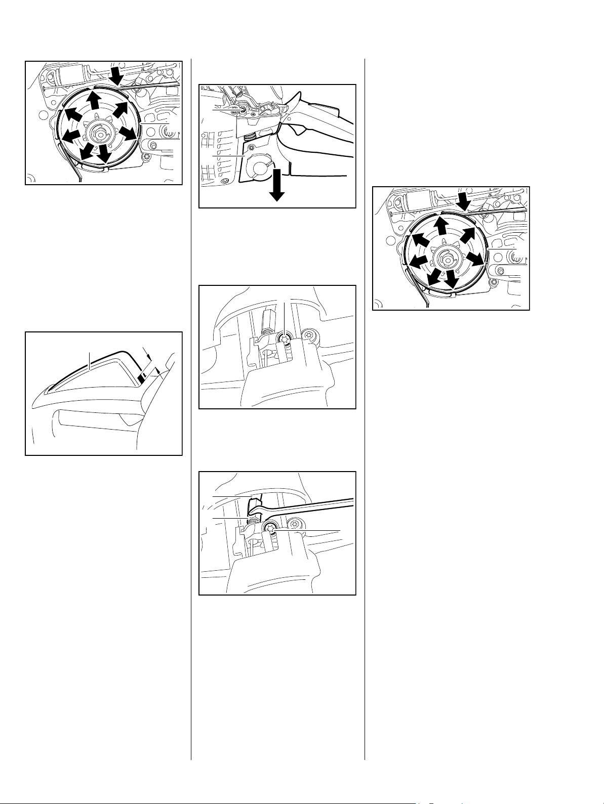
: Release quick release
locks (arrows)
– Using the combination wrench,
turn 1/4 turn counterclockwise
: Remove the shroud (1)
1
– Clean the mating surface, b 16
– Grease the sealing lips of the
new oil seal, b 16
2
1
: Fit the installing sleeve (1)
1141 893 4600
: Slide the oil seal (2) over the
installing sleeve with the sealing
lip facing the crankcase
: Fit the circlip (1)
– Reassemble remaining parts in
reverse order
2410RA087 TG
1
2410RA089 TG
2410RA091 TG
: Push out cap (arrow) with drift (1)
38 MS 241 C

Installation
– Remove the carburetor, b 13.5
– Remove carburetor support,
b 13.8
2
1
: Push in cap (1) with drift (2)
– Reassemble remaining parts in
reverse order
6.5 Cylinder
Before removing the cylinder,
decide whether or not the
crankshaft is to be removed.
With cylinder installed
The crankshaft must be prevented
from twisting by blocking the piston
through the spark plug hole in order
to remove the flywheel and clutch.
– Remove air guide shroud,
b 13.4, versions with manual
fuel pump b 13.4.1, versions
with heating b 13.4.2
– Remove the muffler, b 6.1
2410RA092 TG
– Remove the decompression
valve, b 6.9
– not for version with ErgoStart
– Remove the front handle,
b 10.4
– not for version with heating
– Remove antivibration spring on
front handle, b 10.3.1
– not for version with heating
1
2410RA094 TG
: Carefully pull off the cylinder (1)
1
2410RA095 TG
: Remove the cylinder gasket (1)
With cylinder removed
The crankshaft is blocked by
placing the piston on the wooden
assembly block in order to remove
the flywheel and clutch.
– Remove shroud, b 6.4
– Take off the spark plug boot and
remove the spark plug, b 4
– Remove fan housing, b 9.2
– Remove short circuit wire,
b 7.7.2
– Remove the control unit, b 7.3
– Remove filter base, b 13.3
2410RA093 TG
: Take out the screws (arrows)
2410RA096 TG
: Examine and clean the mating
surface (arrow), b 16
The mating surface must be in
perfect condition and without any
damage whatsoever. Parts with
damaged mating surfaces must be
replaced, b 3.7.
39MS 241 C

22
Installation
22
2
: Examine the intake elbow (1),
replace if necessary. Engine
operation may be impaired even
by the slightest damage, b 3.7
: Remove screws (2)
: Remove intake elbow (1)
1
2410RA097 TG
: Position intake elbow (1)
: Insert and tighten down the
screws (2)
1
1
1
2410RA102 TG
2
– Coat piston, piston rings and
2410RA099 TG
inside of cylinder with oil, b 16
: Fit clamping strap (1)
0000 893 2600 around piston
and piston rings
– Ensure that piston rings are
correctly positioned, b 6.8
The clamping strap (1) must be
fitted in such a way that the piston
rings do not protrude beyond the
piston sides.
: Examine and clean the mating
surfaces (arrows), and remove
any gasket residues, b 16
– Clean mating surface on intake
elbow, b 16
The mating surfaces must be in
perfect condition and without any
damage whatsoever. A new cylinder
must be used if the mating surfaces
are damaged.
Always use a new cylinder gasket
after removing the cylinder.
: Guide new cylinder gasket (1)
2410RA098 TG
over the piston so that the
tab (arrow) faces the spiked
bumper
1
: Place wooden assembly
block (1) 1108 893 4800
between piston and crankcase
Avoid damage to the cylinder
gasket.
2410RA100 TG
: Orient cylinder (1) so that the
intake elbow (2) faces the control
handle
When fitting the cylinder over the
piston, ensure that the clamping
strap securely encloses the piston
and that none of the piston rings
2410RA101 TG
protrudes
– danger of breakage.
: Slide cylinder over piston; the
clamping strap is removed at the
same time
1
2
2410RA103 TG
40 MS 241 C

6.6 Crankshaft
Clutch side half of crankcase
2
1
: Remove clamping strap (1) and
wooden assembly block (2)
Make certain that the cylinder
gasket is oriented according to the
holes.
– Push cylinder home as far as
possible
– Drain fuel tank and oil tank,
b 1.1
– Remove brake band, b 5.2
– Remove oil pump, b 12.3
2410RA104 TG
– Remove oil suction hose,
b 12.2
– Remove brake lever, b 5.3
QuickStop Super, b 5.4
– Remove the front handle,
b 10.4
Version with heating, b 10.4.1
– Remove the tank housing,
b 13.11.5
– Remove the flywheel, b 7.6
– Version with handle heating
Remove generator, b 14.7
– Remove the cylinder, b 6.5
2410RA093 TG
– Remove piston, b 6.7
1
2410RA106 TG
: Remove the circlip (1)
2410RA107 TG2410RA105 TG
The tools from the assembly tool kit
5910 007 2205 are used for
removal and installation.
: Take out the screws (arrows)
: Fit screws (arrows) and secure
cylinder with gasket
: Tighten down the screws through
the holes (arrows) crosswise
– Reassemble remaining parts in
reverse order
– Remove spiked bumper
Always fit new ball bearings and oil
seals when removing the
crankshaft, b 6.6.1 and b 6.3.
21
: Remove screws (1) and pull out
chain tensioner (2)
41MS 241 C

Ignition side half of crankcase
: Align the assembly tool (1) with
the disk (2) 5910 893 2103
against the ignition-side half of
1
2
the crankcase so that the edge
number "24" (arrow) is at the
bottom
: Insert three M5 x 72 screws (3)
through the holes marked "24"
1
2410RA544 TG
and screw them as far as
possible into the crankcase half
: Unscrew screw (1), remove
Loctite residue from the threaded
hole if necessary
: On versions with quick chain
tensioner, remove side plate (2)
2
1
: Unscrew spindle (1) until it no
longer rests on the crankshaft
stub
: Push assembly tool (2) from kit
5910 007 2205 onto the
stud (arrow), twist on and tighten
the nut
: Remove the gasket (1)
3
22
23
2
24
22
24
23
22
23
24
1
33
The tools from the assembly tool kit
5910 007 2201 are used for
2410RA108 TG
removal and installation.
– Use disk 5910 893 2103
The assembly took kit
5910 007 2201 can be expanded
with the disk 5910 893 2103.
The new assembly tool kit
5910 007 2201 contains all three
disks.
2410RA109 TG
1
: Turn the spindle (1)
2410RA110 TG
counterclockwise until the
crankshaft has been forced out of
the ignition-side half of the
crankcase
22
23
24
22
24
23
22
23
24
2410RA111 TG
1
: Turn spindle (1) clockwise until
the crankshaft stub has been
forced out of the ball bearing
The clutch-side half of the
crankcase is pulled off in this way
and the two halves of the crankcase
separated.
– Replace ball bearings and oil
seals, b 6.6.1 and b 6.3
: Adjust the spindle (1) of the
assembly tool
so that the disk (2) rests against
the half of the crankcase
– Left-hand thread
2
The crankshaft (1), connecting
rod (2) and the needle bearing
between them make up a complete
unit and must therefore always be
replaced as a unit.
– Check the two halves of the
crankcase and the grooved ball
bearing, replace if necessary,
b 6.6.1
– Before installation, clean the
crankshaft, b 16
42 MS 241 C
2410RRA112 TG

Installation
Ignition side half of crankcase
Avoid damage to the crankshaft
stub.
Examine and clean the mating
surfaces of the ignition-side half of
the crankcase (including the
cylinder sealing surface) – the
sealing face must not display any
signs of damage, b 16.
: Orient the crankshaft with the
conical crankshaft stub (arrow)
facing the ignition-side ball
bearing
– Wear protective gloves
– risk of burns
1
If the inner race cannot be heated,
the crankshaft can be drawn into the
crankcase with the assembly tool
5910 007 2201.
– Use disk 5910 893 2103.
: Screw the threaded sleeve (1)
5910 893 2420 onto the
completely screwed in spindle as
far as it will go
– Coat the tapered crankshaft stub
with oil.
2410RA113 TG
2
5902RA135 TG
: Fit the screw sleeve (2) over the
thread of the conical crankshaft
stub (1) and screw it on
2
1
22
23
24
22
24
23
22
23
24
1
2
.
: By turning the spindle screw (1),
position disk 5910 893 2103
against the ignition-side half of
the crankcase and orient it so that
the edge number "24" is at the
bottom
2410RA114 TG
2410RA115 TG
– Heat only the inner race of the
ball bearing to approx. 150 °C
(300 °F)
: Press crankshaft stub fully home
The crankshaft must be fitted
rapidly, as the heat is transmitted to
the crankshaft stub and the inner
bearing race contracts.
: Align the crankshaft with the
conical crankshaft stub (arrow)
facing the ignition-side ball
bearing and push it home
: Insert M5x72 screws (2) through
2410RA113 TG
the holes marked "24"
– anti-twist device
: Turn the spindle screw (1)
clockwise
– Draw the ignition-side half of the
crankcase in as far as possible
43MS 241 C

1
22
23
24
22
24
23
22
23
24
1
The crankshaft also turns when it is
drawn in with the installing tool. For
this reason, ensure that the rod
eye (1) always faces upwards
towards the cylinder.
– Remove the installing tool
: Screw two screws (arrows)
M5x72 into the holes on the
ignition side
– for guidance and to prevent
twisting
2410RA116 TG
: Fit a new gasket (1) and secure it
at the guide sleeves (arrows)
– Coat the cylindrical crankshaft
stub with oil
Clutch side half of crankcase
Avoid damage to the crankshaft
stub.
Examine and clean the mating
surfaces of the clutch-side half of
the crankcase (including the
cylinder sealing surface) – the
sealing face must not display any
signs of damage, b 16.
2410RA117 TG
2410RA118 TG
– Wear protective gloves
– risk of burns
– Heat only the inner race of the
ball bearing to approx. 150 °C
(300 °F)
– Align the crankcase half with the
cylindrical crankshaft stub and
the two screws and position it
: Push the crankcase home until it
makes contact
The crankcase must be fitted
rapidly, as the heat is transmitted to
the crankshaft stub and the inner
bearing race contracts
If it is not possible to heat the inner
race, the crankcase half is drawn in
with the assembly tool from kit
5910 007 2205.
– Coat the cylindrical crankshaft
stub with oil
2410RA120 TG
– Align the crankcase half with the
cylindrical crankshaft stub and
2410RA119 TG
the two screws and position it
Ensure that the guide
sleeves (arrows) line up with the
holes and that the housing gasket is
not jammed or buckled.
44 MS 241 C

1
165RA133 TG
2410RA121 TG2410RA122 TG
2410RA119 TG2410RA107 TG
– By turning it, screw the spindle
completely into the assembly tool
: Screw the threaded sleeve (1)
5910 893 2409 onto the spindle
as far as it will go
– Left-hand thread
: Fit threaded sleeve on crankshaft
stub (arrow) and push assembly
tool over the studs
: Hold crankshaft steady and
screw threaded sleeve onto
thread of crankshaft stub by
turning the spindle
counterclockwise
– Release crankshaft and hold
assembly tool steady and
continue turning the spindle until
the assembly tool rests against
the crankcase half.
– Screw nut onto the stud and
tighten it by hand
0001RA494 TG
Ensure that the guide
sleeves (arrows) line up with the
holes and that the housing gasket is
not jammed or buckled.
– Continue turning the spindle of
the assembly tool until the gap
between the halves of the
crankcase is closed
– Unscrew nuts
– Turn the spindle clockwise to
remove the assembly tool
– Remove the two M5x72 screws
which were fitted to prevent
twisting
1
: Turn spindle (1)
counterclockwise until the
crankcase half rests against the
guide sleeves
: Insert the screws (arrows) and
tighten them down crosswise
45MS 241 C

6.6.1 Ball bearing / crankcase
Ignition-side half of the
crankcase
The two halves of the crankcase
can be replaced individually if they
are defective.
New crankcases are delivered with
the relevant components preassembled
1
– see spare parts list
2410RA545 TG
– For versions with quick chain
tensioner, fit side plate
: Coat screw (1) with Loctite,
screw in and tighten, b 16
1
: Fit the circlip (1)
– Examine and install the piston,
b 6.7
– Examine and install the cylinder,
b 6.5
– Install chain tensioner, b 5.7
– Reassemble remaining parts in
reverse order
Those parts which are not supplied
with the new crankcase must be
removed from the old crankcase,
examined and replaced if
necessary.
When fitting a new crankcase, the
machine's serial number must be
stamped on the crankcase with
2.5 mm figure stamps.
If the original crankcase is reused,
the oil seals and grooved ball
bearings must be replaced, all
gasket residues removed and the
mating surfaces cleaned
thoroughly. The mating surfaces
must be absolutely flawless and
2410RA123 TG
clean to guarantee a perfect seal,
b 16.
Examine both halves of the
crankcase for cracks and check all
mating surfaces for signs of
damage.
– Refer also to troubleshooting,
b 3.7
– Remove crankshaft, b 6.6
– Wear protective gloves
– risk of burns
2410RA124 TG2410RA125 TG
: Carefully drive the oil seal out
with a punch
: Examine and clean the
crankcase, replace if necessary.
– Replace ball bearings if the
crankcase is in good condition
1
– Heat the bearing seat of the ball
bearing to approx. 150 °C
(300 °F)
The bearing (1) drops out of its own
accord when this temperature is
reached.
46 MS 241 C

Installation
– Heat the bearing seat of the ball
bearing to approx. 150 °C
(300 °F)
– Position ball bearing so that the
open side (balls visible) faces the
inside of the crankcase
: Press the grooved ball bearing
home as far as possible
The ball bearing must be fitted
rapidly, as it absorbs heat and
expands.
– Check seat of ball bearing, if
necessary, use press arbor
1118 893 7200 to press the ball
bearing fully home in the ball
bearing seat
– Replace ball bearings if the
crankcase is in good condition
1
2410RA126 TG2410RA127 TG
– Heat the bearing seat of the ball
bearing to approx. 150 °C
(300 °F)
The bearing (1) drops out of its own
accord when this temperature is
reached.
Installation
Because the clutch side half of the
crankcase does not have a fixed
bearing seat, the oil pump must be
removed beforehand
– The oil pump serves as a
reference
– Install oil pump, b 12.3
The ball bearing must be fitted
rapidly, as it absorbs heat and
expands.
– Check seat of ball bearing, if
necessary, use press arbor
1118 893 7200 to carefully press
the ball bearing fully home until it
rests against the oil pump
– Remove oil pump, b 12.3
– Install crankshaft, b 6.6
2410RA128 TG
– Install the oil seals, b 6.3
– Reassemble remaining parts in
reverse order
6.7 Piston
Before removing the cylinder,
decide whether the crankshaft is to
be removed, b 6.6
– Remove the cylinder, b 6.5
The clutch side snap ring is not
removed.
Clutch-side half of the crankcase
: Carefully drive the oil seal out
with a punch
– Examine and clean the
crankcase, replace if necessary.
– Heat the bearing seat of the ball
bearing to approx. 150 °C
(300 °F)
– Position ball bearing so that the
centering ring (arrow) points
towards the oil pump
: Press ball bearing fully home (oil
pump)
: Pry the hookless snap ring out of
2410RA129 TG
the recess (arrow) on the ignition
side with a suitable tool
2410RA130 TG
47MS 241 C

1
Installation
1
2
: Push assembly drift (1)
1110 893 4700 through the
installed snap ring
: Push the piston pin (2) out of the
piston with the assembly drift (1)
1110 893 4700
If the piston pin is stuck, tap the end
of the drift gently with a hammer to
loosen it.
The piston must be held steady
during this process to ensure that
jolts are not transmitted to the
connecting rod.
– Remove the piston
– Examine the piston rings and
replace if necessary, b 6.8
2410RA131 TG
– Coat needle bearing with oil and
slide it into the rod eye
Line up the piston so that the
arrow (arrow) in the piston base
points towards the spiked
bumper (exhaust port)
The assembly drift can be inserted
through the fitted snap ring.
– Position the piston on the rod eye
: Push assembly drift (1)
1110 893 4700 with the stub end
first through piston hole and rod
eye (needle cage) and secure
the piston
2
: Remove the sleeve (1)
2410RA133 TG
5910 893 1707 from the installing
tool (2) 5910 890 2210
2
: Attach the snap ring (1) to the
magnet (2) and align it so that the
snap ring gap is on the flat
side (arrow)
1
1
5904RA089 TG
165RA153 TG
1
: Take out the needle bearing (1),
examine and clean it, replace if
necessary
21
2410RA132 TG
– Coat the piston pin (1) with oil
: Fit the piston pin (1) on the stub
of the assembly drift (2) and slide
it into the piston
2
2410RA134 TG
1
: Push the slotted opening of the
sleeve over the magnet and snap
ring
The inner pin (1) must point towards
the flat face of the tool's shank (2).
5904RA090 TG
48 MS 241 C

6.8 Piston rings
– Remove piston, b 6.7
– Remove piston rings from piston
Press the assembly tool down in the
sleeve until the magnet is at the end
of the guide slits.
: Remove sleeve and fit it over the
opposite shaft end of the
assembly tool, with the internal
pin pointing towards the flat
surface.
5904RA091 TG
: Position the installing tool
5910 890 2210 with the taper
sleeve on the piston boss, hold
the piston steady and press the
tool shank home until the snap
ring slips into the groove
The tool must be precisely aligned
in axial direction of the piston pin.
216RA178 TG
– Examine the piston rings and
replace if necessary, b 6.8
– Install the cylinder, b 6.5
2410RA136 TG2410RA137 TG
2410RA138 TG2410RA139 TG
: Use a piece of old piston ring to
scrape the grooves (arrows)
clean
: Align the new piston rings so that
the radiuses at the ends of the
ring (arrows) face upwards
1
The snap ring (1) must be fitted so
that the gap in the ring (arrow)
points upwards in axial direction of
the piston.
– Reassemble remaining parts in
reverse order
2410RA135 TG
49MS 241 C

– Carefully slide the piston rings
over the piston
– danger of breakage
6.9 Decompression valve
– Remove shroud, b 6.4
1
2410RA140 TG
: Position the piston rings so that
the radiuses at the ring gaps
encircle the fixing pins in the
piston grooves (arrows)
: Check the correct installed
position of the piston rings
again (arrows)
– Install the piston, b 6.7
– Reassemble remaining parts in
reverse order
2410RA141 TG
: Unscrew decompression
valve (1)
5902RA164 TG
: Examine the sealing
cone (arrow) on the
decompression valve for signs of
damage
– Use a new decompression valve
if the sealing cone on the
decompression valve does not
seal tightly or is damaged
– Fit the decompression valve by
hand and screw it in
– Screw the decompression valve
tight
– Reassemble remaining parts in
reverse order
50 MS 241 C

7. Ignition system
Exercise extreme caution while
carrying out maintenance and repair
work on the ignition system. The
high voltages which occur can
cause serious or fatal accidents.
Troubleshooting on the ignition
system should always start with the
spark plug, b 3.5
– Remove fan housing, b 9.2
4
1
2
The contactless electronic ignition
system basically consists of a
control unit (1), flywheel (2),
switchgear (3) and solenoid
valve (4).
The ignition module accommodates
all the components required to
control the ignition timing and fuel
flow. There are only three electrical
connections leaving the control unit:
3
Testing of the ignition module is not
limited to only a spark test. If no
ignition spark is obtained or other
functions do not work, a diagnosis
must be carried out according to the
troubleshooting chart; replace
control unit or M-Tronic wiring
harness if necessary.
7.1 Ignition timing
Ignition timing is fixed and cannot
be adjusted during repair work.
Since there is no mechanical wear
in these systems, ignition timing
cannot get out of adjustment during
operation.
7.2 Pre-separator
2410RA142 TG
– Remove fan housing, b 9.2
7.3 Control unit
– Remove fan housing, b 9.2
– Unplug the spark plug boot
1
3
: Remove holders (1) and (2)
carefully from the slits (arrows)
and open
: Pull the ignition lead (3) out of the
guide
2
1
2
2410RA144 TG
1
1. High voltage output for the
ignition lead.
2. Connector tab for black
lead – short circuit wire.
3. Connector tab for red lead
– M-Tronic.
: Remove screw (1)
: Remove pre-separator (2), check
and replace if necessary
– Reassemble parts in reverse
order
2410RA143 TG
2410RA145 TG
: Lift retaining tab (arrow) and
remove angled plug (1)
– Examine insulating sleeve of the
angled plug, clean or replace if
necessary, b 7.7.2
51MS 241 C

1
Installation
1
1
2
1
: Remove screws (1) with washers
– Remove control unit
3
1
2
: Remove wiring harness (1) and
ground wire (2) from the
guides (arrows) and remove
cable holder (3)
– Check ignition lead, replace if
necessary
– Examine the spark plug boot,
replace if necessary, b 7.5
– Troubleshooting, b 3.5
2410RA146 TG
: Position cable holder (1) on the
cylinder and secure it with the
pins on the cylindrical raised
parts
3
2
2410RA147 TG
: Hold cable holder (1) against
cylinder and position control
unit (2)
: Insert screw (3) with washer – do
not tighten
On the cable lug of the ground wire,
the crimped side must face the
screw head.
: Position ground wire (1) so that
2410RA148 TG
the cable lug is pressed fully
home (arrow) and the crimped
side faces the screw head
: Insert screw (2) with washer – do
not tighten
1
2410RA149 TG
1
: Push back ignition module and
slide setting gauge (1)
1111 890 6400 between the legs
of the ignition module and the
magnetic poles of the flywheel
2410RA150 TG
2410RA151 TG
52 MS 241 C

1
1
2
1
N
S
Shown without setting gauge for a
better view.
– Flywheel must turn freely
: Turn the flywheel until the
magnet poles "N/S" (arrows) are
at the control unit (1)
: Press control unit (1) against the
setting gauge and tighten
screws (2) – the cable lug of the
ground wire must be fully seated
– Remove the setting gauge
– Checking correct functioning
– Turn the flywheel: it must not
touch the control unit
2
2
2410RA152 TG
: Orient angled plug (1) so that the
retaining tab (2) faces the muffler
: Press the angled plug (1) straight
onto the connector tags until the
retaining tab (2) snaps into place
– Do not insert the angled plug on
a slant or tilt it
a
1
4
Protective tube (2) must be
positioned snug against the
grommet in the air guide shroud.
2
2410RA154 TG
: Orient wiring harness (1) so that
the protective tube (2) lines up
with the leading edge (arrow) and
the red M-Tronic lead is
underneath the short-circuit
wire (black)
2410RA156 TG
1
2410RA157 TG
23
: Press wiring harness (1)
2410RA155 TG
completely into the
guides (arrows)
1
: Press ground wire (1) completely
into the guide (arrow)
– Ground wire is routed
underneath the wiring harness
: Press the wiring harness (1) into
the guide so that the protective
tube (2) a = ca. 8 mm is seated in
the guide (arrow)
– Ground wire is routed
2410RA153 TG
underneath the wiring harness
: Push the holder (3) into the slit of
the cable holder (4) until it clicks
into place
1
2
2410RA158 TG
: Plug the spark plug boot (1) onto
the spark plug so that it runs
parallel to the air guide shroud
underneath the tab (2)
53MS 241 C

7.4 Spark test check control unit
The engine may start and
accelerate during the test.
1
: Press ignition lead (1) completely
into the guide (arrow)
– Note routing of the ignition lead,
see illustration
Ignition lead and spark plug boot
must not touch the air guide shroud.
1
: Press the holder (1) into the
slit (arrow) until it clicks into place
The ignition test refers only to a
spark test, not the general functions
of the control unit; these are
described in the M-Tronic chapter,
b 8.2, b 8.5.
To spark test the control unit, use
2410RA159 TG
either the ZAT 4 ignition system
tester 5910 850 4503 or the
ZAT 3 ignition system tester
5910 850 4520.
Using the ZAT 4 ignition system
tester 5910 850 4503
1
2410RA160 TG
– Before starting the test, install a
2
new spark plug in the cylinder
and tighten it down firmly.
3
If a spark is visible, the ignition
system is in order.
– If no spark is visible in the
window (2), check the ignition
system with the aid of the
troubleshooting chart, b 7.8,
b 8.5
Using the ZAT 3 ignition system
tester 5910 850 4520
1
3 4
2
– Before starting the test, install a
165RA183 TG
new spark plug and tighten it
down firmly
: Connect the spark plug boot to
the terminal (2)
165RA184 TG
– Reassemble remaining parts in
reverse order
: Connect the spark plug boot to
the input terminal (1). Push the
tester's output terminal (3) onto
the spark plug
Danger! High voltage – risk of
electrocution.
– Crank the engine quickly with the
rewind starter and check
sparkover in the window (2) of
the ignition system tester
: Attach ground terminal (1) to the
spark plug
: Use adjusting knob (4) to set
spark gap to approx. 2 mm,
see window (3)
54 MS 241 C

5
1
3 4
2
165RA185 TG
2310RA127 TG
2310RA128 TG2310RA129 TG
While using the ZAT 3, hold it only
by the handle (4) or position it in a
safe place. Keep fingers or other
parts of your body at least 1 cm
away from the spark window (3),
high-voltage connection (2), ground
connection (5) and the ground
terminal (1).
Danger! High voltage – risk of
electrocution.
– Crank the engine quickly with the
rewind starter and check
sparkover in the window (3) of
the ignition system tester
The engine may start and
accelerate during the test.
If a spark is visible in the
window (3), the ignition system is in
order.
– If no spark is visible in the
window (3), check the ignition
system with the aid of the
troubleshooting chart, b 7.8
7.5 Spark plug boot
– Remove shroud, b 6.4
– Unplug spark plug boot and pull
ignition lead out of the guides,
b 7.3
: Use suitable pliers to pull the
torsion spring out of the spark
plug boot
– Unhook the torsion spring from
the ignition lead
– Pull the boot off the ignition lead
– Check ignition lead, replace if
necessary, b 7.5.1
Installation
– With a new ignition module, use a
pointed tool to pierce the center
of the new lead's insulation
approx. 13 mm from the end of
the ignition lead
: Pinch the hook of the torsion
spring into the center of the
ignition lead (arrow) where it has
been pierced
– Apply STIHL press fluid to the
inside of the spark plug boot,
b 16
: Push the ignition lead and torsion
spring into the spark plug boot
: Ensure that the torsion
spring (arrow) is located in the
recess
– Plug spark plug boot onto spark
165RA188 TG
plug and press ignition lead
completely into the guide, b 7.3
Ignition lead and spark plug boot
must not touch the air guide shroud.
– Reassemble remaining parts in
reverse order
55MS 241 C

7.5.1 Ignition lead
The ignition lead is built into the high
voltage output of the control unit. If
the ignition lead is damaged, the
control unit must be replaced.
– Remove spark plug boot, b 7.5
– Before twisting in the ignition
lead, fill the coil tower with STIHL
multi-purpose grease, b 16
Do not use either graphite grease or
silicone insulating paste.
– Block the piston with the locking
strip, b 4
– Remove the control unit, b 7.3
2
1
: Pull grommet (1) off of high-
voltage output (arrow)
: Twist ignition lead (2) out of
control unit
– Pull the grommet off the ignition
lead
2
– Push grommet onto ignition lead
: Twist ignition lead (2) into control
2410RA161 TG
unit
: Push on the grommet (1)
– Install control unit and adjust air
gap control unit/ flywheel, b 7.3
– Reassemble remaining parts in
reverse order
7.6 Flywheel
1
1
: Unscrew the flywheel nut (1)
2410RA162 TG
3
1
2
: Screw the screws (1) of the
puller (3) 5910 890 4504 into the
flywheel as far as they will go
– Ensure that the screws are
screwed in uniformly
2410RA164 TG
1
2410RA163 TG
For versions with ErgoStart, the new
puller 5910 890 4504 with extended
clamping bridge must be used. The
previous puller 1135 890 4500 is
– For versions with heating, only M
5 x 25 screws can be used to
fasten the puller
– Generator can be damaged
being replaced by the new puller,
– For versions with ErgoStart, do
not damage the pawls
: Turn screw (2) clockwise until the
flywheel comes off the crankshaft
stub
: Unscrew puller (3)
: Use a pointed tool to pierce the
center of the end of the new
ignition lead, which is to be
twisted into the control unit.
but can still be used for the standard
versions.
165RA191 TG
– Remove shroud, b 6.4
– Remove fan housing, b 9.2
5910 890 4504 from flywheel
56 MS 241 C

– Reassemble remaining parts in
reverse order
7.7.2 Removal and installation
– Remove shroud, b 6.4
The flywheel and magnet
poles (arrows) must not display any
signs of damage or blue
discoloration; replace flywheel if
necessary.
– The magnet ring must also be
examined for signs of damage in
versions with handle heating,
b 7.6
– With versions with ErgoStart
pawls, check for damage and
smoothness of motion, b 9.4.
Installation
7.7 Short circuit wire
Ground wire, short-circuit wire and
M-Tronic lead are all combined into
one wiring harness.
0001RA167 TG2310RA110 TG
Make a contact test of the short
circuit wire if the spark plug and
ignition lead with spark plug boot
are in order.
7.7.1 Contact test
– Remove fan housing, b 9.2
– Move the Master Control lever to
0"
"
– Unplug the spark plug boot
– Remove fan housing, b 9.2
– Remove choke rod, b 11.4
1
2
: Remove holders (1) and (2)
carefully from the slits (arrows)
and open
2410RA165 TG
Flywheel and crankshaft stub must
be free from grease for installation.
Ensure that the machined key
(arrow) engages the slot in the
crankshaft.
– Set the air gap between control
unit and flywheel, b 7.3
– Blade receptacle of the short-
circuit wire must touch the
contact spring (arrow) in position
"
0"
Also carry out a contact and
continuity test of the ground wire
between cable lug and contact
spring, replace wiring harness if
necessary.
– If no fault can be found, test the
M-Tronic in accordance with flow
chart, b 7.8
– Reassemble parts in reverse
order
1
2310RA155 TG
2410RA166 TG
: Lift retaining tab (arrow) and
remove angled plug (1)
57MS 241 C

1
1
1
2
: Remove screw (1) with washer
and remove ground wire cable
lug (2)
1
2
: Remove wiring harness (1) and
ground wire (2) from the
guides (arrows)
Versions with heating
2410RA167 TG
: Remove blade receptacle (1) of
the carburetor heating lead
Versions with manual fuel pump
2410RA168 TG
3
: Push out the holder (1) with the
fuel pump at the air guide
shroud (2), remove fuel hose (3)
at the carburetor (arrow) and lay
it on top of the air guide shroud
2410RA170 TG
: Pull plug connector (1) out of the
carburetor support mount (arrow)
2 1
2
1
: Hold the jack (1), press the
2410RA220 TG
tab (arrow) and pull out the
plug (2) – do not tug on the leads
– Turn the carburetor a little in the
direction of the control handle
– Do not overextend fuel hose
2410RA171 TG
2410RA172 TG
All versions
– Remove filter base, b 13.3
1
– Remove contact spring, b 7.7.4
– Remove switch shaft on filter
1
base, b 11.1
2410RA169 TG
: Pull out carburetor heating
lead (1) at the guide (arrow)
: Remove the plug (1)
58 MS 241 C
2410RA173 TG

1
2
2
1
: Remove diagnostic jack (1) with
connector housing (2) from the
guides (arrows)
1
: Pry out and remove the cable
holder (1) at the pin (arrow)
1
: Remove wiring harness (1) from
the guides (arrows) of the air
guide shroud
2410RA174 TG
: Pull out grommet (1) with wiring
harness
1
2410RA175 TG
: Remove ground wire (1) from the
guides (arrows)
2
1
2410RA176 TG
: Remove ground wire (1) from the
guide (arrow)
: Remove the switch shaft (2)
2410RA177 TG
1
: Pull the retaining tab (1) in the
direction of the leads and open
the cover (2)
121
2410RA178 TG
: Pull blade receptacles (1) out of
the insulating sleeve (2)
– Check blade receptacles and
insulating sleeves, clean or
replace insulating sleeves if
necessary
With a new wiring harness, the
grommets and the plugs as well as
the insulating sleeve are preassembled.
2410RA179 TG
2410RA180 TG
2410RA181 TG
59MS 241 C

Installation
1
2
: Push the blade receptacle (1) of
the red lead (M-Tronic) into the
rear receptacle (arrow) of the
insulating sleeve (2)
– Crimped side faces forward
The leads must not be reversed.
1
1
2
2410RA182 TG
: Close and lock the cover (1) so
that the tab (2) engages the
slit (arrow) of the retaining tab (3)
– the retaining tab must fit snugly
against the insulating sleeve
3
2
1
The ground wire (4) must be routed
behind the protective tube (2)
– facing the cylinder.
1
2410RA184 TG
2
2410RA187 TG
: Push the grommet (1) into the
opening (arrow) in the air guide
shroud (2) until it is flush with the
edge of the air guide shroud
1
2
: Push the blade receptacle (1) of
the black lead (short-circuit wire)
into the front receptacle (arrow)
of the insulating sleeve (2)
– Crimped side faces forward
The leads must not be reversed.
The protective tube (1) must rest
2410RA183 TG
against the grommet (2).
: If necessary, push the wiring
harness towards the grommet (2)
until the protective tube (1) rests
against the grommet (2)
4
1
3
2
: Orient the wiring harness (1) so
that the protective tube (2) and
angled plug (3) face the control
unit
2410RA185 TG
234
: Orient wiring harness so that the
red lead (1) is above and the
black lead (2) is underneath the
ground wire (3)
Starting at the protective tube (4),
the ground wire branches out into a
thin black lead (M-Tronic) and a
thick blue lead (short-circuit wire).
When inserting the ground wire, the
small guide rib (arrow) must be
between these two leads
2410RA186 TG
2410RA189 TG
60 MS 241 C

1
4
3 2
5
: Press the red M-Tronic lead (1),
ground wire (2) and black
lead (3) of the short-circuit wire
all the way into the
guides (arrows)
The protective tube (4) must start at
the beginning of the rib and
protective tube (5) must rest against
the beginning of the rib.
1
: Slide cable holder (1) with the
hinge into the slot (arrow) of the
air guide shroud
1
2410RA190 TG
: Check that the leads are properly
seated in the guides and press
the cable holder (1) with the
pin (arrow) into the mount until it
snaps into place
3
2
1
: Orient diagnostic jack (1) so that
the black leads (2) face the
control handle
2410RA191 TG
: Press diagnostic jack (1) and
connector housing (3) into the
guides (arrows)
2
2410RA192 TG
: Press the diagnostic jack (1) into
the mount so that it is seated
completely in the recess (arrows)
and the tabs (2) snap into place
1
2410RA193 TG
: Press plug (1) into the mount as
far as it will go
1
2
1
2410RA194 TG
2410RA195 TG
: Turn the cable holder (1) towards
the cylinder and position it
2
: Using wiring tool 5910 890 4000,
press the blue ground wire (1)
and black short-circuit wire (2)
into the guide (arrow) so that the
wires are snug against the air
guide shroud
61MS 241 C
2410RA196 TG

3
1 2
1
2
1
: Orient plug (1) and jack (2) that
the tab (3) lines up with the
mount (arrow) – do not twist the
leads
: Plug connector (1) into jack (2)
until the tab (3) clicks into place in
the mount (arrow)
2
1
: Press the plug connection (1)
into the mount (2) of the
carburetor support so that the
tab (arrow) engages in the recess
of the plug connection
2410RA188 TG
: Slide the blade receptacle (1) of
the blue ground wire, with the
crimped side facing the cam (2),
into the guide (arrow) as far as it
will go
: Hook ground wire (1) into the
2410RA197 TG
guides (arrows)
– Push switch shaft onto filter base,
b 11.1
– Install contact spring, b 7.7.4
2410RA199 TG
2
: Check the routing of the blue
ground wire (1) and black shortcircuit wire (2), if necessary,
press them completely into the
guide (arrow) using wiring tool
5910 890 4000 – wires must rest
snug against the air guide shroud
1
2
2410RA200 TG
: Using wiring tool 5910 890 4000,
press the blue ground wire (1)
and black short-circuit wire (2)
into the guides so that the
markings (arrows) are located at
the guide ribs
2410RA201 TG
1
2410RA202 TG
– Push on the carburetor and
– Install filter base, b 13.3
observe cable routing as well as
– Conduct a function test of the
switch shaft, b 11.1
installation position of the
M-Tronic and, if present, the
heating system, b 8.4
62 MS 241 C

Versions with heating
1
: Press fuel return line (3)
completely into the guide (arrow)
1
2410RA204 TG
: Orient blade receptacle (1) so
that the crimped side faces the
carburetor
: Press blade receptacle (1) onto
the connector tab (arrow) of the
heating switch as far as it will go
1
: Press carburetor heating lead (1)
completely into the guide (arrow)
Versions with manual fuel pump
2410RA198 TG
1
Push the new fuel suction hose (1)
completely onto the
connectors (arrows)
All versions
1
2410RA169 TG
Ground wire: Crimped side of the
cable lug (1) must be visible.
: Position cable lug (1) between
control unit (2) and stop (3)
42 3
: Press ground wire (1) completely
into the guide (arrow)
2410RA227 TG2410RA203 TG
– Ground wire is routed
underneath the wiring harness
1
2
: Orient angled plug (1) so that the
retaining tab (2) faces the muffler
: Press the angled plug (1) straight
onto the connector tags until the
retaining tab (2) snaps into place
– Do not insert the angled plug on
a slant or tilt it
2410RA205 TG
2
1
3
: Push the holder (1) with the fuel
pump into the recess in the air
guide shroud (2) as far as it will
go
: Insert screw (4) with washer and
tighten
2410RA226 TG
63MS 241 C

a
1
The short-circuit wire must be
7.7.4 Contact spring
1
seated firmly in the eye of the
contact spring, if necessary, carry
4
out a contact and continuity test,
b 7.7.1.
– Remove the filter base from the
23
2410RA155 TG
2410RA207 TG
studs, b 13.3
Protective tube (2) must be
positioned snug against the
grommet in the air guide shroud.
: Press the wiring harness (1) into
the guide so that the protective
tube (2) a = approx. 8 mm is
seated in the guide (arrow)
– Ground wire is routed
underneath the wiring harness
: Push the holder (3) into the slit of
the cable holder (4) until it clicks
into place
1
2
: Orient wiring harness (1) so that
the protective tube (2) lines up
with the leading edge (arrow) and
the red M-Tronic lead is
underneath the short-circuit
wire (black)
: Press wiring harness (1)
completely into the
guides (arrows)
– Check the air gap between
control unit and flywheel, adjust if
necessary, b 7.3
2
Ignition lead (1) must be seated
completely in the guide.
: Press the holder (2) carefully into
the slit (arrow) until it clicks into
2410RA206 TG
place
– Conduct a function test of the
switch shaft, b 11.1
– Reassemble remaining parts in
reverse order
1
1
: Turn filter base (1) to the side
2410RA209 TG
1
2410RA208 TG
2
2310RA151 TG
: Lift contact spring (1) slightly and
guide it over the tab (arrow)
: Press contact spring (1) out of
the guides in the filter base (2)
7.7.3 Ground wire
Testing and installation of ground
wire is the same as for the shortcircuit wire
– Check contacts and operation,
b 7.7
64 MS 241 C

2
1
2
: Press contact sleeve (1) of the
short-circuit wire out of the
contact spring (2)
– Examine contact spring, replace
if necessary
Installation
1
2
1
2410RA210 TG
: Position contact spring (1)
against the guide (arrows)
: Lift contact spring (1) slightly at
the connection of the short-circuit
wire and guide it over the tab (2)
– do not overextend the contact
spring
2410RA212 TG
: Push the contact spring (1) into
the guide (arrows) as far it will go,
until the tab surrounds the
contact spring
– Install filter base, b 13.3
1
1
2310RA154 TG
2310RA155 TG
: Push the contact sleeve (1) of the
short-circuit wire into the
eye (arrow) of the contact
spring (2) as far as it will go
2410RA211 TG
Before pushing the contact
spring (1) all the way in, lift it slightly
and guide it over the switch shaft –
2 mm maximum.
: Checking correct functioning
2310RA153 TG
– Blade receptacle of the shortcircuit wire must touch the
contact spring (arrow) in position
"
0"
– Reassemble remaining parts in
reverse order
65MS 241 C

7.8 Troubleshooting, ignition system
– Contacts shorted (threads)?
– Clean, adjust or replace spark plug,
Engine does not run
Stop switch:
– in position "
Check spark plug:
– Smeared with oil, black?
– Sooted?
– Electrode gap correct?
b 7.5
F"?
Check spark plug boot:
– Firmly seated on spark plug (torsion
spring)?
– Torsion spring hook in center of ignition
lead?
– Spark plug boot damaged?
– Replace spark plug boot and/or torsion
spring if necessary,
b 7.5
Check ignition:
with ZAT 3 or ZAT 4
(use ZAT 3 as main spark gap
see TI 32.94),
b 7.4
1
66 MS 241 C

1
Spark
present?
no
Air gap:
– Check control unit/ flywheel,
– adjust if necessary, b 7.3
Check flywheel:
– Have pole shoes turned blue?
– Replace flywheel if necessary,
b 7.6
Check short circuit wire:
– Wire damaged?
– Plug connections firmly seated?
– Check continuity, replace wiring harness if
necessary, b 7.7.1
yes
Check ignition lead:
– Severe chafing?
– Spark plug boot: Holes / cracks?
– Resistance of spark plug boot to ground:
Required 1.5...12 kΩ
– Check resistance of spark plug lead to
ground, (spark plug boot and control unit have
been removed)
Value: Required < 10 Ω,
replace spark plug boot and/or ignition module
if necessary,
b 7.5.1
2
3
67MS 241 C

2
Switch shaft
Check correct operation:
– Short circuit wire chafed?
– Function between contact spring and
contact of the switch shaft:
– Position "
– Position "
– Replace wiring harness if necessary,
F" = no connection
0" = connection
b 11.1
3
yes
Spark
present?
no
Control unit
needs to be replaced,
b 7.3
Machine
runs?
yes
no
Engine runs smoothly,
troubleshooting procedure
completed
68 MS 241 C
– Look for fault in fuel or carburetor
system
– Check engine for leaks
– Check position of flywheel on
crankshaft,
b 3.6, b 6.2

8. M-Tronic
The fully electronic M-Tronic engine
management system controls the
ignition timing and fuel flow, taking
all external conditions into account.
A basic or standard setting of the
carburetor is no longer required.
The M-Tronic electronically adjusts
the fuel-air mixture in the carburetor.
The M-Tronic controls all operating
states such as start, idle, part
throttle and full throttle while
accounting for the external
conditions, e.g., use at varying
attitudes, as well as changing
temperatures or fuel quality – the
carburetor does not have any
adjusting screws.
Troubleshooting and test
procedures are described in the
following chapters, Testing, b 8.2,
Troubleshooting, b 8.5.
8.1 Calibrating the control unit
If the outstanding running behavior
and usual performance or maximum
speed of the engine can no longer
be attained, the usual engine
performance can be attained again
by calibrating the control unit.
2410RA546 TG
A regulating cycle only starts if the
machine is operated for
approximately 2 seconds under
constant conditions.
If the maximum speed is not
reached...
– Examine air filter, clean or
replace if necessary, b 13.1
– Examine the spark arresting
screen (if installed); clean or
replace it if necessary, b 6.1
– Check chain tension, adjust if
necessary
– Check chain lubrication
– Set Master Control lever to
Start }
– Start engine and let it warm up
If the control unit or carburetor is
replaced during servicing...
– Remove the saw chain and guide
bar
– Reinstall the chain sprocket
cover
– Set Master Control lever to
Start }
– Start machine – do not blip the
throttle trigger
After completion of the following
procedure, the Master Control lever
must be moved from Start } to
STOP 0 without pressing the throttle
trigger.
– Let the machine warm up for at
least 60 seconds in the Start }
position and then move the
Master Control lever to STOP 0
– Calibration is completed
The control unit is adjusted to the
carburetor while the engine runs in
the position Start }.
The machine must be switched off
immediately for the information to
be stored in the control unit.
– Carry out five uniform cuts to
length
– speed between 8000 rpm and
11200 rpm, log diameter
approx. 30 cm
– If the outstanding running
behavior and the usual
performance are not attained,
continue troubleshooting and test
procedures as described under
Testing, b 8.2,
Troubleshooting, b 8.5
69MS 241 C

8.2 Testing
8.2.1 Test preparations
The following steps must be carried
out before testing.
– Carry out troubleshooting
according to troubleshooting
chart, b 8.5
– Remove shroud, b 6.4
– Remove the air filter, b 13.1
1
: Remove diagnostic jack (1) from
the guide (arrow)
1
2410RA213 TG
: Press the diagnostic jack (1) into
the mount (arrow) until it is fully
home
2410RA216 TG
– Remove coarse dirt from around
the screwed connections, control
unit, switchgear, solenoid valve
and diagnostic jack
8.2.2 Connect the test lead
– Remove shroud, b 6.4
– Remove the air filter, b 13.1
1
: Remove the plug (1)
1 2
: Orient the plug (1) of the
M-Tronic test lead
5910 840 0903 so that the
angled shapes (arrows) match
between diagnostic jack (2) and
plug (1)
2
2410RA173 TG
1
– Reassemble remaining parts in
reverse order
8.2.3 Check screwed and plug connections as well as switch
– Carry out test preparations,
2410RA214 TG
b 8.2.1
There must be a reliable connection
for communication between control
unit, switching device and solenoid
valve. If communication between
control unit and solenoid valve is
interrupted or faulty, the control unit
does not initiate an ignition spark.
– In the event of a malfunction or if
there is no ignition spark, first
check the plug connections and
wiring harness between control
device and solenoid valve
2410RA215 TG
: Push the plug (1) of the
M-Tronic test lead
5910 840 0903 into the
diagnostic jack (2) as far as it will
go
– After completion of the test
procedure, unplug the test lead
from the diagnostic jack
70 MS 241 C

Versions with heating
2410RA222 TG
1
2
All versions
1
Screw (1) must be tight.
Leads (arrows) must be seated
completely and firmly in the blade
receptacles and the cable lug.
12
1
2410RA217 TG
2
: Remove blade receptacle (1) and
contact sleeve (2)
: Push out the holder (3) with
ground wire (4) at the air guide
shroud (5) and lay it aside
Versions with manual fuel pump
1
5
3
4
2410RA219 TG
Plug (1) must be seated completely
and firmly in the recess of the
solenoid.
: If necessary, remove plug (1) and
check contacts
2
2410RA221 TG
3
Plug connection (1) must be
pressed together completely –
locking lug (3) must engage the
recess.
: If necessary. remove the plug
connection (1) from the
mount (arrow), remove the
plug (2) and check the contacts,
b 8.2.3
2410RA218 TG
3
: Push out the holder (1) with the
fuel pump at the air guide
shroud (2), remove fuel hose (3)
at the carburetor (arrow) and lay
it on top of the air guide shroud
1
: Set Master Control lever (1) to
2410RA220 TG
position }; the cam on the
lever (2) must actuate the
microswitch (arrow) – clicking
sound
– If the microswitch is not actuated
by the lever at the carburetor,
replace lever if necessary,
b 13.6.6
– If the microswitch does not
function although it was actuated,
then the switchgear must be
replaced, b 8.4
71MS 241 C

Versions with heating
3
1
2
1
2
2410RA225 TG
1
2410RA227 TG
: Push the holder (1) with the
ground wire (2) into the recess in
the air guide shroud (3) as far as
it will go
: Push ground wire (2) into the
guide (arrow)
2
1
: Push contact sleeve (1) into
heating switch
– Push in contact sleeve
completely
: Push blade receptacle (1) onto
2410RA223 TG
the connector tab
– Push on blade receptacle all
the way
: Press lead (2) completely into the
guide (arrow) of the filter base
Versions with manual fuel pump
2410RA224 TG
3
: Push the holder (1) with the fuel
pump into the recess in the air
guide shroud (2) as far as it will
go
: Push the new fuel suction
hose (1) completely onto the
connectors (arrows)
– Reassemble remaining parts in
reverse order
8.2.4 Checking the solenoid valve
– Carry out test preparations,
2
b 8.2.1
– Check screwed and plug
1
connections, b 8.2.3
– Check contacts and operation,
b 8.2.5
2410RA226 TG
– Move the Master Control lever to
position "F"
– Connect the test lead, b 8.2.2
: Press lead (2) completely into the
guide (arrow)
: Press fuel return line (3)
completely into the guide (arrow)
72 MS 241 C

Measuring resistance
2410RA222 TG
1
2
1
1
2410RA166 TG
2
: Measure resistance between
plugs (1) and (2) of the M-Tronic
test lead
Target value: between 28 and
42 ohms
– If the target value is not attained,
check electrical leads for
interruption, e. g., due to cable
breakage between solenoid
valve and diagnostic jack, or
contact due to damaged
insulation
8.2.5 Checking the start detection function
– Carry out test preparations,
b 8.2.1
: Set Master Control lever (1) to
2410RA228 TG
position }; the cam on the
lever (2) must actuate the
microswitch (arrow) – clicking
sound
Versions with manual fuel pump
– Push out the holder with the fuel
pump and set it aside, b 8.2.3
Versions with heating
– Disconnect leads, push out the
holder with the heating switch
and set it aside, b 8.2.3
All versions
: Lift retaining tab (arrow) and
remove angled plug (1)
– Check angled plug, dismantle
and clean if necessary, b 7.7.2
– Set Master Control lever to
position }
– Connect the test lead, b 8.2.2
– Check screwed and plug
connections, b 8.2.3
1
2
: Disconnect the plug (1) from the
solenoid valve (2) – the solenoid
valve must not be twisted; if
necessary, hold the solenoid
valve in place when
disconnecting the plug
2410RA229 TG
73MS 241 C

Versions with manual fuel pump
Checking the ground connection
2
– Install holder with fuel pump,
push new fuel hose onto
connector and press fuel return
line into the guide, b 8.2.3
2
1
3
– Connect M-Tronic test lead to
multimeter
: Insert black plug (1) in the "com"
/ "ground" jack and the red
plug (2) in the "volt" / "ohm" jack
– Set multimeter to "diode test"
: Test diode on
switchgear (3) (microswitch) in
accordance with multimeter
instruction manual
If the switchgear (microswitch) is
intact and the Master Control lever
is set to the } position, the
following target values will be
attained:
– Measurement in direction of flow,
target value: 0.3 volts to 0.7 volts
– Move the Master Control lever to
position F
– Measurement in direction of flow,
required: 1.2 volts to infinity
– Observe display, e.g., (O.L.)
or (1.)
– If the required values are not
attained, replace switchgear and
repeat test procedure, b 8.4
– If the required values are not
attained again, replace wiring
harness; it may be possible to
reuse the previous switchgear,
b 7.7.2
Versions with heating
2410RA230 TG
– Install holder with heating switch,
press leads in and on and into the
guides, b 8.2.3
– Reassemble remaining parts in
reverse order
8.2.6 Checking the wiring harness
– Carry out test preparations,
b 8.2.1
– Check contacts and operation,
b 8.2.3
– Set Master Control lever to
position STOP 0
: Lift retaining tab (arrow) and
remove angled plug (1)
– Check angled plug, dismantle
and clean if necessary, b 7.7.2
1
: Measure the resistance between
blade receptacle (1) with black
lead and screw (2) at the control
unit
Target value: < 10 ohms.
2
: Measure the resistance between
contact spring (1) and screw (2)
at the control unit
1
Target value: < 10 ohms.
If the target values are not
attained
2410RA166 TG
– Check electrical leads for
interruption, e. g., cable
breakage – if necessary, replace
wiring harness, b 8.2.6
2410RA231 TG
1
2410RA232 TG
74 MS 241 C

Check leads between control unit
and diagnostic jack
– Connect the test lead, b 16
2
1
– Check continuity between leads
and blade receptacles
– Blade receptacles must be
firmly connected to the leads; in
the event of contact problems,
the wiring harness must be
replaced, b 8.2.3, b 8.2.6
Check leads between solenoid
valve and diagnostic jack
– Connect the test lead, b 8.2.2
Target value: < 10 ohms
1
2
2410RA236 TG
: Measure the resistance between
blade receptacle (1) with red lead
and black plug (2) of the
diagnostic cable
Target value: < 10 ohms.
2
1
: Measure the resistance between
blade receptacle (1) with black
lead and red plug (2) of the
diagnostic cable
Target value: < 10 ohms.
– Versions with manual fuel pump,
2410RA233 TG
remove fuel pump and set it
aside, b 8.2.3
2
: Disconnect the plug (1) from the
solenoid valve (2) – the solenoid
valve must not be twisted; if
necessary, hold the solenoid
2410RA234 TG
valve in place when
disconnecting the plug
1 2
: Measure the resistance between
black lead (1) at the plug of the
solenoid and red plug (2) of the
diagnostic cable
Target value: < 10 ohms
If the target values are not
attained
1
– Check contact surfaces on plug
of the plug connection, as well as
checking electrical leads for
interruption, e. g., cable
2410RA229 TG
breakage
– If the contact surfaces on the plug
are damaged in the plug
connection between wiring
harness and switchgear, the
wiring harness must be replaced,
b 7.7.2, if the contacts in the
jack are damaged, the
switchgear must be replaced,
b 8.4
– Reassemble remaining parts in
reverse order
If the target values are not
attained
– Check contact between blade
receptacle of the switch shaft and
contact spring
2410RA235 TG
: Measure the resistance between
red lead (1) at the plug of the
solenoid and black plug (2) of the
diagnostic cable
75MS 241 C

8.3 Wiring harness
Versions with heating
All versions
– The M-Tronic leads and the
ground wire are all combined into
one wiring harness; removal and
installation are described in the
chapter "Short-circuit wire",
b 7.7.2
8.4 Switchgear
– Remove shroud, b 6.4
– Remove the air filter, b 13.1
– Check switchgear, b 8.2.5
– Remove choke rod, b 11.4
– Remove baffle, b 13.2
– Remove filter base, b 13.3
1
2
: Remove blade receptacle (1)
: Remove heating element (2)
from the studs
Versions with manual fuel pump
1
2410RA240 TG
: Pull plug connector (1) out of the
carburetor support mount (arrow)
2 1
2410RA243 TG
1
: Pull holder (1) of the switchgear
over the studs (arrows) and lay it
aside
1
: Disconnect the fuel hose (1)
2410RA239 TG
2
1
: Push out the holder (1) with the
fuel pump on the air guide
shroud (2) and lay it on top of the
air guide shroud
: Hold the jack (1), press the
tab (arrow) and pull out the
2410RA241 TG
2410RA242 TG
plug (2) – do not tug on the leads
2410RA172 TG
76 MS 241 C

21
1
2
The fuel hose does not have to be
removed from the carburetor
support.
: Carefully pull out the carburetor
with the fuel hose over the studs
and lay it aside – do not
overextend the fuel hose
1
2
: Turn the throttle shaft lever (1)
slightly in the direction of fullthrottle, then turn the starter
shaft (2) until the choke shutter is
closed
2410RA244 TG2410RA245 TG
: Pull the wiring harness (1) out of
the guide (arrow) and pull it out
between the special bolt (2) and
the starter shaft (3)
: Check lever on the starter
shaft (3), replace if necessary,
b 13.6.6
Installation
With a new switchgear, first the
leads must be inserted in the guides
of the switchgear.
Leads and plug connections must
not be damaged.
2
3
2410RA247 TG
2410RA249 TG
: Orient plug (1) so that the guide
pin (arrow) faces the carburetor
: Push the plug (1) into the jack of
the solenoid (2) as far as it will go
21
3
2410RA250 TG
: Orient wiring harness (1) so that
the red lead runs underneath the
black lead
1
Choke shutter must be closed.
: Guide wiring harness (1)
3
between the special bolt (2) and
the starter shaft (3)
1
2
: Disconnect the plug (1) from the
solenoid valve (2) – the solenoid
valve must not be twisted; if
necessary, hold the solenoid
valve in place when
disconnecting the plug
2410RA248 TG
: Press red lead (1) and black
lead (2) completely into the
guides (arrows) of the
switchgear (3)
– see illustration
2410RA246 TG
77MS 241 C

Versions with manual fuel pump
21
3
1 2
1
: Position the wiring harness (1) so
that the protective tube (2) rests
against the beginning of the
guide
: Press the red and black leads
completely into the
guides (arrows)
Versions with heating
4
5
1
2 3
: Check the lead (1) of the
thermostatic switch, if necessary,
press it completely into the
guides (arrows) on the base of
the carburetor and route it behind
the pin (5)
Plug connectors (2) and (3) and the
generator lead (4) must be seated
completely in the guides.
2410RA251 TG
: Check seat of the fuel return
line (1), if necessary. press it
completely into the
guides (arrows)
All versions
1
Washer (1) must be fitted.
2410RA252 TG
1
2
: Orient plug (1) and jack (2) that
2410RA253 TG
the tab (3) lines up with the
opening (arrow) – do not twist the
leads
: Plug connector (1) into jack (2)
until the tab (3) clicks into place
2
1
2410RA078 TG
: Press the plug connection (1)
into the mount (2) of the
carburetor support so that the
tab (arrow) engages and snaps
into place in the recess of the
plug connection
– Plug connection (1) must be
seated firmly in the mount (2)
– Push on the carburetor as far as
it will go – pay attention to cable
routing and make sure not to
pinch any leads
2410RA254 TG
2410RA188 TG
2410RA256 TG
Do not remove the fuel hose from
the carburetor support.
: Carefully push the carburetor (1)
with the fuel hose (2) over the
studs (arrows) – do not
overextend the fuel hose
78 MS 241 C

Versions with heating
Versions with manual fuel pump
4
2
All versions
1
1
: Press thermostatic switch
lead (1) completely into the
guide (arrow) of the air guide
shroud
– Lead (1) must form a loop at the
plug connection
3
2
1
5
2410RA257 TG
: Push the holder (1) with the fuel
pump into the mount of the air
guide shroud (2) as far as it will
go; push new fuel hose (3) onto
the connectors (arrows)
: Fuel return line (4) must be
seated completely in the
guide (5); if necessary, press the
fuel return line (4) into the
guide (5) again
2410RA258 TG
3
1
2410RA259 TG
: Push the holder (1) of the
switchgear over the studs so that
the tab rests against the
pin (arrow)
– Install filter base, b 13.3
– Reassemble remaining parts in
reverse order
2410RA260 TG
: Slide the heating element (1)
over the studs so that the hole
engages the pin (2)
: Orient the crimped side of the
blade receptacle (3) so that it
faces the carburetor
: Push the blade receptacle (3)
completely onto the connector
tab (arrow)
79MS 241 C

8.5 Troubleshooting, M-Tronic
8.5.1 Engine does not start
Engine does not start
– Set Master Control lever
to position }
– Check ignition (spark
plug, spark plug boot,
ignition spark), b 7.4
– Check start detection,
(microswitch, actuating
lever), b 8.2.5
Can engine
be started?
no
no
Ignition spark
present?
Mechanically
OK?
yes
yes
yes
no
Troubleshooting completed
– Test ignition system
according to flow chart
"Ignition system
troubleshooting", b 7.8
yes
Is it possible to start
the engine?
no
– Examine switch gear,
clean or replace if
necessary, b 8.2.5
– Check start detection and
wiring harness electrically,
b 8.2.5, b 8.2.6
– Check solenoid valve,
b 8.2.4
80 MS 241 C
Are target values
attained?, b 8.2.5
yes
Are target values
attained? b 8.2.4
yes
– Look for a fault in the fuel
path, check engine for
leaks, b 13.11, b 6.2
no
no
– Examine switch gear and/
or wiring harness, clean or
replace if necessary,
b 8.2.5, b 8.2.6
– Replace carburetor,
b 13.5

8.5.2 Engine does not start in
position }
Engine does not start in
position } – engine floods.
Can the flooded engine be
started in position F?
Is it possible to start
the engine?
no
yes
Troubleshooting completed
– Check start detection
(microswitch actuation)
clean if necessary
– Check start detection,
wiring harness and plug
connections,
b 8.2.5,b 8.2.3
Mechanically
OK?
yes
Are target values
attained?, b 8.2.5
yes
– Look for a fault in the fuel
path (inlet needle, lever,
spring, membrane),
check engine for leaks,
b 13.11, b 6.2
no
no
– Examine switch gear,
clean or replace if
necessary, b 8.2.5, b 8.4
– Examine switch gear and/
or wiring harness, clean or
replace if necessary,
b 8.2.5, b 8.2.3
81MS 241 C

8.5.3 Engine speed drops
under load
– low power
Engine speed drops under load –
low power
– Examine air filter, clean or
replace if necessary, b 13.1
– Calibrate control unit,
b 8.1
yes
Troubleshooting completed
Machine OK?
no
– Look for a fault in the fuel
path, check engine for
leaks,
b 13.11, b 6.2
82 MS 241 C

8.5.4 Ignition – no ignition
spark
No ignition spark
– Set Master Control lever
to position }
– Check the flywheel,
(two pairs of poles?) b 7.6
– Check air gap between
control unit and flywheel,
b 7.3
Can engine
be started?
no
Combination
OK?
yes
Air gap
OK?
yes
– Test ignition system
according to flow chart
"Ignition system
troubleshooting", b 7.8
yes
no
no
Troubleshooting
completed
Establish correct control unit/
flywheel combination
– Set correct air gap, b 7.3
83MS 241 C

8.5.5 Engine stops suddenly
Engine stops suddenly
– Check fuel path (fuel pick-up
body, tank vent, fuel hoses),
b 13.11
– Check plug connection on
control unit or between wiring
harness and switchgear
– Check start
detection (microswitch,
actuating lever), clean if
necessary
Machine
OK?
no
Fuel path
OK?
yes
Connection
and firm seat of the
plugs OK?
yes
Mechanically
OK?
yes
yes
no
no
no
Troubleshooting
completed
– Repair fuel
system
– Check plug connections,
replace wiring harness
and/or switching device, if
necessary b 8.2.3,
b 8.3, b 8.4
– Replace switchgear,
b 8.4
– Check start detection, wiring
harness and plug connections,
b 8.2.5, b 8.2.6
– Check solenoid valve,
b 8.2.4
Are target values
attained?, b 8.2.5
yes
Are target values
attained?, b 8.2.4
yes
no
no
– Examine switch gear
and/or wiring harness,
clean or replace if
necessary, b 8.2.5,
b 8.2.6, b 8.3, b 8.4
– Replace carburetor,
b 13.5
– Check engine for leaks,
b 6.2
84 MS 241 C

8.5.6 Cut-off speed not reached
Maximum speed less than
13000 rpm
– Check air filter and spark arrestor screen
(if present) in muffler, clean or replace if
necessary, b 13.1, b 6.1
– Check saw chain tension and chain
lubrication
–Calibrate control unit,
b 8.1
– Check plug connection on
control unit, b 8.2.3
– Check start detection,
wiring harness and plug
connections, b 8.2.5
b 8.2.3
Maximum speed
greater than 13000
rpm?
no
Connection
and firm seat of the
plug
OK?
yes
Are target values
attained?, b 8.2.5
yes
no
no
Troubleshooting
completed
– Check plug, replace
insulating housing or
wiring harness if
necessary, b 7.3
– Replace switchgear,
b 8.4
yes
– Look for a fault in the fuel
path, check engine for
leaks,
b 13.11, b 6.2
85MS 241 C

9. Rewind starter
9.1 General
If the action of the starter rope
becomes very stiff and the rope
rewinds very slowly or not
completely, it may be assumed that
the starter mechanism is in order
but plugged with dirt. At very low
outside temperatures, the
lubricating oil on the rewind spring
may thicken and cause the spring
windings to stick together. This has
a detrimental effect on the function
of the starter mechanism.
To clean the rewind spring, it is
sufficient to apply a few drops of a
standard solvent-based degreasant
not containing any chlorinated or
halogenated hydrocarbons to the
rewind spring.
Carefully pull out the starter rope
several times and allow it to rewind
until its normal smooth action is
restored.
9.2 Fan housing
– Remove shroud, b 6.4
1
: Remove screw (1) with sleeve
and screws (arrows)
– Lift hand guard slightly and
remove fan housing
1
Installation
: First insert and position
segment (1) in the slit (arrow) on
2310RA201 TG
the fan housing
1
1
2310RA203 TG
Before installing, lubricate the
rewind spring and starter post with
STIHL special lubricant, b 16.
If clogged with dirt or pitch, the
entire starter mechanism, including
the rewind spring, must be removed
and disassembled. Take particular
care when removing the rewind
spring.
– Clean all components
Versions with ErgoStart
– Relieve the tension of the rewind
spring, b 9.4
2
2
: Push out segment (1) on the
pegs (2) on the opposite side
through the holes with drift
– Examine fan housing and
segment, replace if necessary.
2
: Press segment (1) as far as it will
go into the pegs (2)
2310RA202 TG
1
– Lift hand guard slightly and
position fan housing
: Insert and tighten screw (1) with
sleeve and screws (arrows)
2
2310RA202 TG
2310RA201 TG
– Reassemble remaining parts in
reverse order
86 MS 241 C

9.3 Pawls
Versions with ErgoStart
– Remove fan housing, b 9.2
– Relieve the tension of the rewind
spring, b 9.5
1
: Carefully ease the spring (1) off
the starter post
– Remove pawl
Installation
: Position the spring (1) so that the
loop of the spring encloses the
peg of the pawl and the curved
part of the spring (arrow) is
located in the groove in the
starter post
2310RA204 TG
: Then slide the straight part of the
spring over the starter post until it
engages in the groove
– Remove ErgoStart, b 9.4
Two pawls are installed in the
1
version with ErgoStart. Removal is
the same as with the standard
version.
– Grease the mounts of the new
2310RA206 TG
pawls, b 16
– Insert the new pawls and oil the
pegs of the pawls with resin-free
lubricating oil, b 16
Installation
2
3
1
– Press new pawl into hole (arrow)
and grease the peg (1), b 16
The guide loop of the spring must
run along the pawl (arrow).
Checking correct functioning
2310RA205 TG
– Pull starter rope, the rope rotor
turns, and the peg at the pawl
moves in the direction of the
anchor loop – the pawl moves
outward
– Reassemble remaining parts in
reverse order
1
Washer (1) must be fitted.
: Position spring (2) so that its
2310RA207 TG
anchor loops engage the pegs of
the pawls and the curved part of
the spring (arrow) is located in
the groove of the rope rotor post
: Then slide the straight part (3) of
the spring over the starter post
until it engages in the groove
– Reassemble remaining parts in
reverse order
2310RA208 TG
87MS 241 C

9.4 ErgoStart
Installation
Checking correct functioning
The spring may still have spring
tension stored in it, thus release the
spring tension before any assembly
procedure:
– Pull out the starter until the
engine turns – the preloaded
spring is relaxed
– Remove fan housing and, if
necessary, segment, b 9.2
4
3 2 1
: Remove the circlip (1)
: Remove washer (2) and
carrier (3)
: Remove spring housing (4)
1
1
: Install torsion springs in pawls (1)
– observe installation
position (arrows)
1
2310RA209 TG
2
: Push pawls (1) onto the posts (2)
on the flywheel, in the process
pretensioning the torsion springs
and positioning them on the
support ribs (arrow)
The pawls must move freely and
rest against the stop due to the
spring force.
533RA198 TG
2
: Push spring housing (1) over the
rope rotor post into the pawls of
the rope rotor (2) – the pawls
must engage in the spring
housing
2 1 3 4
5902RA581 TG
1
2310RA210 TG
2310RA211 TG
: Insert the carrier (1) in the spring
1
1
housing so that the
recess (arrow) engages the
anchor loop (2) of the rewind
spring
1
: Push out circlips (arrows)
: Pull out pawls (1) and remove
torsion springs
2710RA165 TG
: Push on the pawls (1) so that
they can move towards the
middle of the flywheel as far as
2
: Fit washer (3)
: Fit the circlip (4)
2710RA274 TG
– Do not overextend circlip
– Reassemble remaining parts in
reverse order
they will go
– Clean the mounts of the
pawls (1), b 16
: Push circlips (2) into place
88 MS 241 C

9.5 Rope rotor
Relieve tension of rewind spring
The system will not be under
tension if the starter rope or rewind
spring is broken.
– Remove fan housing and
segment, b 9.2
Versions with ErgoStart
1
: Remove the washer (1)
– Install pawl or pawls and spring,
b 9.3
– Install starter rope, b 9.6
2
– Tension the rewind spring, b 9.7
– Grease the pegs of the pawl or
pawls, b 16
2310RA213 TG
– Reassemble remaining parts in
reverse order
– Remove ErgoStart, b 9.4
All versions
1
2
: Pull out the starter rope (1)
about 5 cm, then hold the rope
rotor (2) steady
– Still holding the rope rotor steady,
take three full turns off the rope
rotor
The rewind spring must be relieved.
: Carefully pull off the rope rotor (2)
–The rewind spring may pop out
– Examine the rope rotor, replace if
necessary.
– Coat the hole in the rope rotor
with STIHL special lubricant,
b 16
Installation
2310RA212 TG
9.6 Starter rope / starter grip
– Remove fan housing and
segment, b 9.2
Versions with ErgoStart
– Remove ErgoStart, b 9.4
All versions
– Relieve the tension of the rewind
spring, b 9.5
The rewind spring will not be under
tension if the starter rope is broken.
– Remove any remaining rope from
the rope rotor if necessary
The starter rope must not be
shortened.
– Pull out the rope with the starter
grip and carefully release the
rope rotor
– Remove the starter rope; remove
any remaining scraps of rope,
b 9.6
– Remove spring and pawl or
pawls, b 9.3
1
: Fit the rotor on the starter post so
that the inner loop of the
spring (arrow) enters the
recess (1)
The recess in the hub of the rope
rotor acts as carrier for the anchor
loop.
– Fit the washer.
2310RA214 TG
89MS 241 C

1
1
: Push starter rope (1) out a short
distance and undo the knot
– Pull starter rope out of rope rotor
and fan housing.
: Tie one of the two special knots
shown above at the end of the
rope in the starter grip.
2310RA215 TG
Pull the rope through the grip until
the knot at the end of the rope is in
the recess (arrow)
1
: Then thread the rope (1) through
165RA227 TG
the opening (arrow)
4903RA132 TG2310RA216 TG
: Pull starter rope (1) into rotor until
the knot rests in the
recess (arrow) of the rope rotor
– Tension the rewind spring, b 9.7
– Reassemble remaining parts in
reverse order
9.7 Tensioning the rewind spring
– Remove fan housing and
segment, b 9.2
2
2310RA218 TG
: Thread the new starter rope into
the starter grip from above
1
: Thread starter rope (1) into rope
4903RA131 TG
rotor
– Secure the rope (1) with a simple
overhand knot
1
: Pull out part of the starter rope (1)
2310RA217 TG
: Turn starter rope (1) with rope
rotor (2) six times clockwise
The rewind spring is now tensioned.
Hold the tensioned rope rotor firmly,
as the rewind spring will be
damaged if it jumps back suddenly.
2310RA219 TG
90 MS 241 C

1
2
: Hold the rope rotor (1) steady
: Pull out the twisted starter
rope (2) with the starter grip and
straighten it out
2
1
When the starter rope is fully
extended, it must still be possible to
rotate the rope rotor at least
another turn before the maximum
spring tension is reached. If not, the
spring tension must be reduced,
otherwise it will break.
Reduce spring tension
Pull the rope out, hold the rope rotor
2310RA220 TG
steady and take off one turn of the
rope.
– Reassemble remaining parts in
reverse order
9.8 Replacing the rewind Spring
– Troubleshooting, b 3.4
The replacement spring is supplied
ready for installation and secured in
a spring housing.
Install new rewind spring
1
2
2310RA224 TG
– Lubricate replacement spring
with frame with a few drops of
STIHL special lubricant before
installing it, b 16
: Position replacement spring with
frame in the fan housing so that
the outer anchor loop (1) is
positioned over the mount for the
loop (2) and aligns with the
mount (arrow)
: Hold the starter grip firmly to
keep the rope (1) tensioned
: Let go of the rope rotor (2) and let
the starter rope rewind slowly
1
The rewind spring is correctly
tensioned when the starter grip (1)
sits firmly in the rope guide
bushing (arrow) without drooping to
one side. If this is not the case, the
rewind spring must be tensioned by
one additional turn.
– Wear face shield and protective
gloves
2310RA221 TG
– risk of injury
– Remove fan housing and
segment, b 9.2
– Relieve the rewind spring if
necessary and remove the rope
rotor, b 9.5
– Remove any fragments of the old
spring
If the rewind spring no longer
produces sufficient tension, it must
be replaced.
A worn rewind spring may still be
under tension while installed.
2310RA222 TG
– Lay a blanket over the assembly
area and remove the rewind
spring from the fan housing
2310RA226 TG
: Starting at the outer anchor loop,
push the new rewind spring
through the openings (arrows)
into the mount of the fan housing
– in the process, the frame is
removed
91MS 241 C

Reinstalling a rewind spring that
has popped out
Versions with ErgoStart
Install new rewind spring
1
: Press the frame (1) against the
rewind spring and turn it slightly
clockwise until the rewind spring
is completely seated
The rewind spring may pop out.
– Carefully remove the frame and
keep it
– The frame is reused as an
installation tool for installing
rewind springs that have popped
out
If the rewind spring pops out during
installation, fit it in the fan housing
as follows:
2310RA227 TG
– Arrange the rewind spring (1) as
shown in the illustration
: Insert outer anchor loop in the
recess (arrow) of the fan housing
1
1
2310RA223 TG
: Check washer (1) and replace if
necessary
2310RA230 TG
1
2
1
Make certain that the
rewind spring (1) is inserted
completely and the outer anchor
loop is seated in the anchor loop
mount (arrow), if necessary, press
the rewind spring completely into
the mount in the fan housing.
– Secure the rewind spring so that
it cannot pop out
– Install the rope rotor, b 9.5
– Reassemble remaining parts in
reverse order
2310RA228 TG
: Fit the rewind spring (1) in the
spring housing in a circular
fashion, working in clockwise
direction while holding the
inserted turns of the spring in
place
The further course of action is the
same as for "Installing a new rewind
spring".
– Lubricate replacement spring
with frame with a few drops of
1
STIHL special lubricant before
installing it, b 16
Position replacement spring with
frame in the fan housing so that the
2310RA231 TG
outer anchor loop (1) is positioned
over the mount for the loop (2) and
aligns with the mount (arrow)
The further course of action is the
same as for "Installing a new rewind
spring" in versions without
ErgoStart.
2310RA225 TG
92 MS 241 C

1
Make certain that the rewind
spring (1) is inserted completely
and the outer anchor loop is seated
in the anchor loop mount (arrow), if
necessary, press the rewind spring
completely into the mount in the fan
housing.
– Secure the rewind spring so that
it cannot pop out
Reinserting a popped out rewind
spring into the frame
In versions with ErgoStart, the
rewind spring mount sits lower, thus
the rewind spring can only be
inserted directly into the fan housing
premounted in a frame.
If the rewind spring pops out during
2310RA229 TG
installation, fit it in the frame as
follows:
1
– Install the rope rotor, b 9.5
– Reassemble remaining parts in
reverse order
5902RA608 TG
: Insert anchor loop in the
recess (arrow) of the frame
: Fit the rewind spring (1) in the
frame in a circular fashion,
working in counterclockwise
direction while holding the
inserted turns of the spring in
place
The further course of action is the
same as for "Installing a new rewind
spring" in versions with ErgoStart.
93MS 241 C

10. Maintaining the antivibration elements
The front handle / tank housing and
crankcase are connected by
vibration-damping springs, rubber
buffers and stop buffers.
Damaged springs rubber buffers
and stop buffers must always be
replaced.
10.1 Antivibration element on oil tank
The antivibration elements are
located in the area of the oil tank
and are fastened to the bottom of
the machine.
– Remove the front handle,
b 10.4, versions with heating,
b 10.4.1
1
2
: Twist out spring (1) with bearing
plug (2)
– Inspect spring with plug, replace
if necessary
Installation
2
2310RA233 TG
3
: Push the chain catcher (3) into
the mount so that it engages
under the bumper strip (2)
: Screw in the screw (1) and
tighten it
– Reassemble remaining parts in
reverse order
10.2 Antivibration element on fuel tank
2
1
2410RA301 TG
2
: Remove screw (1)
: Remove the chain catcher (2)
– Remove the tank housing,
b 13.11.5
1
Bearing plug (1) must be twisted
2410RA300 TG
into the spring (2) as far as it will go.
: Twist spring (2) with bearing
plug (1) into the mount (arrow) as
far as it will go
– Install the tank housing,
b 13.11.5
1
2310RA234 TG
1
2410RA302 TG
: Remove screw (1)
94 MS 241 C

Versions with heating
Installation
1
: Remove screw (1) on front
handle
All versions
1
1
: Remove screws (1)
: Push tank housing (2) down
slightly and hold it there
1
: Remove cover (1)
2410RA303 TG
2
: Push the antivibration
element (1) slightly upward and
lift it out of the guide (arrow)
2310RA236 TG
: Remove antiivibration
element (1) between crankcase
and tank housing
– Inspect spring and plug, replace if
necessary
2310RA237 TG
1
2310RA238 TG
2
1
– Push tank housing down slightly
and hold it there
: Orient antivibration element so
that the tab (1) faces the
crankcase and push it bearing
plug (2) first between crankcase
and tank housing
: Push bearing plug (2) through
the opening
: Push the bearing plug (3) into the
mount (arrow)
3
1
2310RA239 TG
1
: Push front handle out of the
mount (arrow) on the peg (1)
– Do not remove screws on front
handle
2310RA240 TG
: Position cover (1) so that it
engages the peg (arrow)
2410RA304 TG
95MS 241 C

2
front handle
The antivibration element is
between front handle and cylinder.
1
10.3 Antivibration element on
1
: Push tank housing upward until
the peg (1) of the front
handle engages in the
mount (arrow)
4
2
1
3
5
: Raise tank housing (1)
2410RA304 TG
: Position bearing stopper (1)
: Coat screw (2) with Loctite,
screw in and tighten, b 16
Versions with heating
2310RA241 TG
2
– Remove shroud, b 6.4
– Remove the air filter, b 13.1
2410RA306 TG
1
1
2410RA302 TG
: Remove screw (1)
– Remove the front handle,
b 10.4
2410RA307 TG
: Orient bearing plugs (2) and
cover (3) so that the holes align
with the hole on the tank housing
: Screw in and tighten
screws (5) and (4)
: Position bearing plug (1) and
insert and tighten screw (2)
– Reassemble remaining parts in
reverse order
1
2
: Twist out bearing plug (1) and
unhook retainer (arrow)
: Twist out spring (2) and push
retainer (arrow) out of front
handle
– Inspect spring and bearing plug
and retain, replace if necessary
2310RA243 TG
96 MS 241 C

Installation
5902RA246 TG
2
1
2
3
2
1
: Push retainer (1) with the small
nipple into the hole in the front
handle (2)
: Twist spring (3) onto the
peg (arrow) as far as it will go
: Position bearing plug (1) against
2310RA244 TG
cylinder
: Coat screw (2) with Loctite,
screw in and tighten, b 16
– Reassemble remaining parts in
reverse order
10.3.1 Antivibration element on handlebar, version with heating
31
1
1
2410RA306 TG
: Twist out bearing plug (1) and
unhook retainer (arrow)
: Twist out spring (2) and pull out
retainer (arrow)
Installation
2
0001RA219 TG
1
: Hook retainer (arrow) onto
bearing plug (1)
: Push bearing plug (1) into the
spring as far as it will go
– Install the front handle, b 10.4
2310RA245 TG
: Remove screws (1) and (2)
: Remove the antivibration
element (3) completely
: Insert retainer (1) with the nipple
in the holder (2)
2
2410RA308 TG
1
2
: Twist spring (2) onto the peg
: Hook retainer (arrow) onto
bearing plug (1)
: Twist bearing plug (1) into the
spring (2) as far as it will go
0001RA219 TG
97MS 241 C

13
– Replace stop buffer
10.3.3 Filter base buffers
2
: Position antivibration element (1)
against front handle and cylinder
: Screw in the screw (2) and
tighten it
: Coat screw (3) with Loctite,
screw in and tighten, b 16
– Reassemble remaining parts in
reverse order
10.3.2 Stop buffer
The stop buffers are installed
between crankcase and tank
housing on the ignition and clutch
side.
Installation
2410RA309 TG
1
– Orient the stop buffer (1) on both
sides – the conical pegs (arrow)
facing the crankcase
– To simplify installation, coat the
conical pegs with STIHL press
fluid, b 16
: Press the stop buffers (1) with the
pegs on the inside of the
crankcase completely into holes
– to simplify assembly, twist the
stop buffers while pressing them
in
– Remove filter base, b 13.3
1
2410RA311 TG
: Remove screw (1)
: Push tank housing (2) down
slightly and hold it there
1 1
2
2310RA249 TG
– Remove the tank housing,
b 13.11.5
1
: Pry out stop buffers (1) on the
ignition and clutch sides
2410RA313 TG
: Press out the buffers (1) on the
underside (arrows)
– Check buffers (1) and replace if
necessary
2410RA312 TG
The conical pegs must enclose the
holes completely.
2410RA310 TG
– Reassemble remaining parts in
reverse order
98 MS 241 C

Installation
1 1
: Lift front handle (1) slightly at the
2
side and remove it from the
guide (arrow).
: Orient buffers (1)
– conical pegs facing the
holes (arrows)
– To simplify installation, coat the
conical pegs with STIHL press
fluid, b 16
: Press the buffers (1) with the
conical pegs completely into the
holes (arrows) –to simplify
assembly, twist the buffers while
pressing them in
: Push tank housing (1) upward
2410RA314 TG
and hold it there
: Screw in the screw (2) and
tighten it
– Reassemble remaining parts in
reverse order
10.4 Front handle
– Remove shroud, b 6.4
1
2310RA253 TG
1 1 2
: Remove screws (1) on the
underside of the machine and lift
front handle (2) out of the
mount (arrow)
1
2310RA157 TG
The conical pegs (arrows) must
enclose the holes completely on the
reverse.
2410RA315 TG
: Remove screw (1)
– Take out screws
1
: Remove front handle (1) from the
lower guide
2410RA302 TG
– Remove and examine front
handle (1), replace if necessary
– Examine the antivibration spring
and replace if necessary, b 10.3
1
2410RA315 TG
0001RA232 TG
99MS 241 C
 Loading...