

Page 1

STIH)
STIHL MS 240, 260
2013-09
Page 2

Contents
RA_165_00_01_05
1. Introduction 3
2. Safety Precautions 5
3. Specifications 6
3.1 Engine 6
3.2 Fuel System 6
3.3 Ignition System 6
3.4 Chain Lubrication 6
3.5 Tightening Torquese 7
4. Troubleshooting 9
4.1 Clutch 9
4.2 Chain Drive,
Chain Brake,
Chain Tensioner 10
4.3 Chain Lubrication 11
4.4 Rewind Starter 12
4.5 Ignition System 13
4.6 Carburetor 15
4.7 Engine 18
5. Cutting Attachment 19
5.1 Chain Catcher 19
6. Clutch 20
6.1 Clutch Drum 22
7. Chain Brake 23
7.1 Checking Operation 23
7.2 Removing and Installing
the Brake Band 23
7.3 Brake Lever 25
7.4 Cam Lever 26
7.5 Pins 27
7.6 Side Chain Tensioner 28
7.6.1 Front Chain Tensioner 29
7.6.2 Quick Chain
Tensioner 29
7.7 Bar Mounting Studs 30
8. Engine 31
8.1 Muffler / Spark
Arresting Screen 31
8.2 Leakage Test 32
8.2.1 Preparations 33
8.2.2 Vacuum Test 34
8.2.3 Pressure Test 34
8.3 Oil Seals 35
8.4 Removing and
Installing the Shroud 36
8.5 Cylinder 37
8.6 Crankshaft 40
8.6.1 Removing and
Installing 40
8.6.2 Bearings / Crankcase 45
8.7 Piston 47
8.7.1 Removal 47
8.7.2 Installing 48
8.8 Piston Rings 49
8.9 Decompression Valve 50
9. Ignition System 51
9.1 Ignition Timing 51
9.2 Ignition Module 51
9.2.1 Removing and
Installing 51
9.3 Testing the
Ignition Module 54
9.4 Spark Plug Boot /
Ignition Lead 55
9.5 Flywheel 56
9.6 Short Circuit Wire 57
9.6.1 Testing 57
9.6.2 Removing and
Installing 57
9.6.3 Ground Wire 60
9.7 Ignition System
Troubleshooting 61
10. Rewind Starter 64
10.1 General 64
10.2 Removing and
Installing 64
10.3 Pawl 64
10.4 Rope Rotor 65
10.5 Starter Rope / Grip 66
10.6 Tensioning the Rewind
Spring 67
10.7 Replacing the Rewind
Spring 68
11. Servicing the
AV System 70
11.1 Annular Buffer on
Chain Catcher 70
11.2 Annular Buffer at
Clutch Side 70
11.3 Annular Buffer at
Ignition Side 71
11.4 Stop Buffer 72
11.5 Handlebar 72
11.6 Handlebar with
Handle Heating 73
12. Control Levers 76
12.1 Switch Shaft 76
12.1.1 Removing and
Installing 76
12.2 Throttle Trigger/Interlock
Lever 77
13. Chain Lubrication 80
13.1 Pickup Body 80
13.2 Oil Suction Hose 80
13.3 Oil Delivery Hose 81
13.4 Non-Adjustable
Oil Pump 81
13.5 Adjustable Oil Pump 82
13.6 Valve 83
14. Fuel System 85
14.1 Air Filter 85
14.2 Removing and Installing
the Carburetor 85
14.3 Leakage Test 86
14.4 Servicing the
Carburetor 87
14.4.1 Inlet Needle 89
14.4.2 Fixed Jet 89
14.4.3 Pump Diaphragm 90
14.4.4 Choke Shaft /
Choke Shutter 91
14.4.5 Adjusting Screws 91
14.5 Adjusting the
Carburetor 92
14.5.1 Basic Setting 92
14.5.2 Standard Setting 93
q
© ANDREAS STIHL AG & Co. KG, 2013
1MS 240, MS 260, MS 260 C
Page 3

Contents
14.6 Throttle Rod 94
14.6.1 Removing and Installing
the Intake Manifold 94
14.6.2 Impulse Hose 96
14.7 Tank Vent 96
14.7.1 Testing 96
14.7.2 Removing and
Installing 97
14.8 Fuel Intake 98
14.8.1 Pickup Body 98
14.8.2 Fuel Suction Hose 98
14.8.3 Removing and Installing
the Tank Housing 99
15. Heating System 100
15.1 Carburetor Heating 100
15.1.1 Testing the Complete
System 100
15.1.2 Testing the Heating
Element 100
15.1.3 Thermostatic Switch 101
15.2 Carburetor Heating
System Troubleshooting
Chart 103
15.3 Handle Heating
System 104
15.3.1 Troubleshooting 104
15.4 Removing and Installing
the Heater Switch 104
15.4.1 Heater Switch
Ground Wire 105
15.5 Removing and Installing
Heating Element in
Rear Handle 106
15.6 Removing and Installing
the Heating Element
in the Handlebar 108
15.7 Removing and Installing
the Generator 108
15.7.1 Handle Heating and
Generator Troubleshooting Chart 110
15.7.2 Test Connections and
Test Values 112
15.8 Wiring Harness 114
16. Special Servicing
Tools 116
17. Servicing Aids 118
2 MS 240, MS 260, MS 260 C
Page 4

1. Introduction
This service manual contains
detailed descriptions of all the repair
and servicing procedures specific to
this power tool.
You should make use of the
illustrated parts lists while carrying
out repair work. They show the
installed positions of the individual
components and assemblies.
Refer to the latest edition of the
relevant parts list to check the part
numbers of any replacement parts.
A fault on the machine may have
several causes. To help locate the
fault, consult the troubleshooting
charts for all assemblies and
systems in this manual and the
"STIHL Service Training System".
Refer to the “Technical Information”
bulletins for engineering changes
which have been introduced since
publication of this service manual.
Technical information bulletins also
supplement the parts list until a
revised edition is issued.
The special tools mentioned in the
descriptions are listed in the chapter
on "Special Servicing Tools" in this
manual. Use the part numbers to
identify the tools in the
"STIHL Special Tools" manual. The
manual lists all special servicing
tools currently available from
STIHL.
Symbols are included in the text and
pictures for greater clarity.
The meanings are as follows:
In the descriptions:
: = Action to be taken as
shown in the illustration above
the text
– = Action to be taken that is
not shown in the illustration
above the text
In the illustrations:
A Pointer
aDirection of movement
1
3
2
219RA000 TG
Servicing and repairs are made
considerably easier if the machine
is mounted to assembly stand (3)
5910 890 3100. To do this, secure
the mounting plate (2) 5910 850
1650 to the assembly stand with two
screws (1) and washers.
The screws must not project since
they, depending on the machine,
may damage housings when the
machine is clamped in position.
The above operation is not
necessary with the new assembly
stand 5910 890 3101 since the
mounting plate is already fitted.
@ 4.2 = Reference to another
chapter, i.e. chapter 4.2
in this example
Service manuals and all technical
information bulletins are intended
exclusively for the use of properly
equipped repair shops. They must
not be passed to third parties.
3MS 240, MS 260, MS 260 C
Page 5
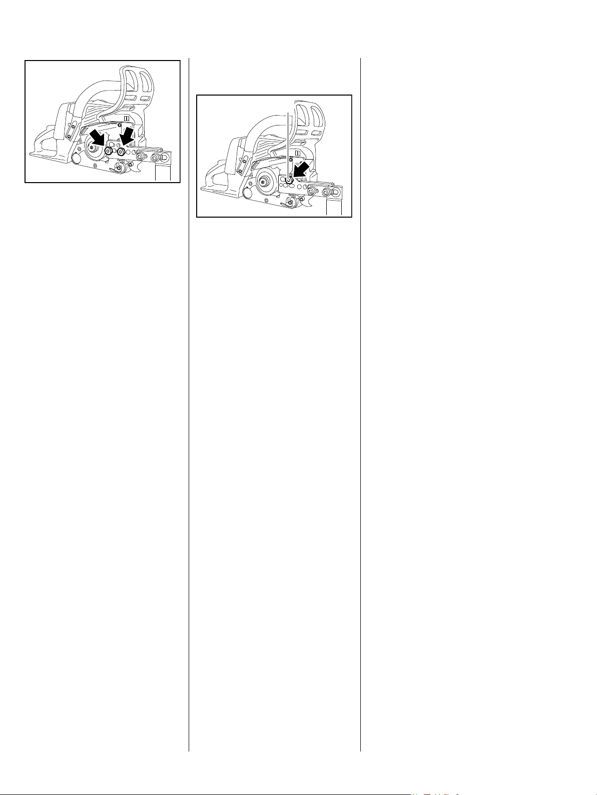
Engage the bar mounting studs in
the outer bores in the mounting
plate and secure the saw in position
with the nuts (arrows).
The chain sprocket cover and
cutting attachment have to be
removed before mounting the saw
to the assembly stand – pull the
hand guard toward the handlebar.
Versions with Quick Chain
Tensioner
1
165RA000 TG
165RA468 TG
There is only one bar stud on these
versions. It is pushed through the
upper hole (arrow) in the mounting
plate and secured with the nut (1).
The machine is held in position on
the mounting plate by the screw
heads on the crankcase.
Always use original STIHL
replacement parts.
They can be identified by the STIHL
part number,
the { logo and the
STIHL parts symbol K.
This symbol may appear alone on
small parts.
Storing and disposing of oils
and fuels
Collect fuel or lubricating oil in a
clean container and dispose of it
properly in accordance with local
environmental regulations.
4 MS 240, MS 260, MS 260 C
Page 6

2. Safety Precautions
If the power tool is started up in the
course of repairs or maintenance
work, observe all local and countryspecific safety regulations as well
as the safety precautions and
warnings in the instruction manual.
Gasoline is an extremely flammable
fuel and can be explosive in certain
conditions.
Always wear suitable protective
gloves for operations in which
components are heated for
assembly or disassembly.
Improper handling may result in
burns or other serious injuries.
Do not smoke or bring any fire,
flame or other source of heat near
the fuel. All work with fuel must be
performed outdoors only. Spilled
fuel must be wiped away
immediately.
Always perform leakage test after
working on the fuel system and the
engine.
5MS 240, MS 260, MS 260 C
Page 7

3. Specifications
3.1 Engine
MS 240 MS 260, MS 260 C
Displacement: 41.6 cm
3
50.2 cm
3
Bore: 42 mm 44.7 mm
Stroke: 30 mm 32 mm
Engine power to ISO 7293: 2.1 kW (2.85 bhp)
at 9500 rpm
2.6 kW (3.5 bhp)
at 9500 rpm
Maximum permissible engine speed
(with bar and chain): 13000 rpm 14000 rpm
Versions with catalytic converter
Maximum permissible engine speed
13000 rpm
(with bar and chain):
Idle speed: 2800 rpm 2800 rpm
Clutch: Centrifugal clutch without
linings
Centrifugal clutch without
linings
Clutch engages at: 3600 rpm 3600 rpm
Crankcase leakage test
at gauge pressure: 0.5 bar
under vacuum: 0.5 bar
3.2 Fuel System
Carburetor leakage test at
0.8 bar
gauge pressure:
Operation of tank vent at
0.5 bar
gauge pressure:
Fuel: as specified in instruction
manual
3.3 Ignition System
Air gap between ignition
module and fanwheel: 0.15...0.30 mm
Spark plug (suppressed): NGK BPMR 7 A
Electrode gap: 0.5 mm
3.4 Chain Lubrication
Speed-controlled oil pump with reciprocating piston and
manual flow control
Oil pump without adjustable
delivery rate:
Oil pump with adjustable
delivery rate:
7.5 (+/- 2.5) cm
10000 rpm
4.5...11.5 cm
10000 rpm
3
/min at
3
/min at
6 MS 240, MS 260, MS 260 C
Page 8

3.5 Tightening Torquese
DG and P (Plastoform) screws are used in polymer and light metal components. These screws form a
permanent thread when they are installed for the first time. They can be removed and installed as often as
necessary without impairing the strength of the screwed assembly, providing the specified tightening torque is
observed.
For this reason it is essential to use a torque wrench.
Fastener Thread size For component Torque
Nm
Countersunk screw P 4x12 Cover plate/sprocket cover (quick chain
tensioner)
Screw M 4x8 Cover plate/chain tensioner 3.0 4)
Collar screw M 8x21.5 Bar mounting 23.0 1)
Collar screw M10/M 8 Bar mounting/quick chain tensioner 30.0 1)
Screw M 4x12 Cover, chain brake/crankcase 3.0 4)
M 10x1 Decompression valve (MS 260) 14.0
Screw B 4.9x9.5 Spark arresting screen/muffler 2.0
Screw M 3.5x12 Generator/crankcase 2.0 1)
Screw P 6x32.5 Handlebar, top (polymer)/tank housing 5.0
Screw P 6x21.5 Handlebar, bottom (polymer)/tank housing 5.0
Screw P 6x19 Handlebar, top and bottom/tank housing
(version with handle heating)
Screw P 4x19 Handle molding 1.6
Screw M 5x12 Retaining plate/annular buffer 8.0 4)
Screw M 4x16 Hand guard/crankcase (micro-encapsulated) 4.0 4)
Nut M 5 Slotted nut, shroud/stud, cylinder 3.5
Screw P 6x19 Chain catcher/plug 2.8
Screw M 5x12 Spiked bumper
(with self-locking nut) 7.5
Screw M 5x20 Crankcase 9.0
Collar nut M 5 Air filter/tank housing 2.0
Screw M 4x16 Fan housing 4.0 4)
M 12x1L Carrier (clutch) 50.0
Screw M 4x12 Oil pump/crankcase 3.0 4)
Screw P 6x26.5 Annular buffer, tank housing/crankcase
(ignition side)
Screw M 5x12 Annular buffer plate/crankcase (ignition side) 8.0 4)
Screw P 6x19 Annular buffer, tank housing/crankcase
(clutch side)
Screw M 5x16 Muffler/crankcase/cylinder
(version with catalytic converter and MS 260)
2.5
7.0
5.0
5.5
10.0 1), 4)
Letter
4)
7MS 240, MS 260, MS 260 C
Page 9

Fastener Thread size For component Torque
Nm
Screw M 5x12 Muffler/crankcase/cylinder (MS 240) 10.0 1), 4)
Nut M 8x1 Flywheel 33.0 3)
Screw M 4x8 Side plate/crankcase 3.0 4)
Screw M 4x16 Side plate/crankcase (quick chain tensioner) 3.0
Screw M 3x20 Clamp/manifold 0.5
M 5x8.5 Stud/cylinder 1.4 2)
Nut M 5 Carburetor 3.5
Screw M 5x20 Cylinder/crankcase 11.0 2), 4)
M 14x1.25 Spark plug 25.0
Screw M 5x20 Ignition module/crankcase (micro-
encapsulated)
Remarks:
1) Loctite 242 or 243, medium strength
2) Loctite 270, high strength
3) Degrease crankshaft/flywheel and mount oil-free
4) Screws with binding head
7.0 4)
Remarks
Use the following procedure when refitting a DG or P screw in an existing thread:
Place the screw in the hole and rotate it counterclockwise until it drops down slightly.
Tighten the screw clockwise to the specified torque.
This procedure ensures that the screw engages properly in the existing thread and does not form a new thread
and weaken the assembly.
Coat micro-encapsulated screws with medium strength Loctite 242 or 243 before reinstalling.
Power screwdriver setting for polymer: DG and P screws max. 500 rpm
Do not use an impact wrench for releasing or tightening screws.
Do not mix up screws with and without binding heads.
8 MS 240, MS 260, MS 260 C
Page 10

4. Troubleshooting
4.1 Clutch
Condition Cause Remedy
Saw chain stops under load at full
throttle
Saw chain rotates at idle speed Engine idle speed too high Readjust with idle speed screw LA
Loud noises Clutch springs stretched or fatigued Replace all clutch springs
Clutch shoes badly worn Install new clutch
Clutch drum badly worn Install new clutch drum
(counterclockwise)
Clutch springs stretched or fatigued Replace the clutch springs or install
new clutch
Clutch spring hooks broken Replace the clutch springs
Needle cage damaged Fit new needle cage
Clutch shoe retainer broken Fit new retainer
Clutch shoes and carrier worn Install new clutch
9MS 240, MS 260, MS 260 C
Page 11

4.2 Chain Drive, Chain Brake, Chain Tensioner
Condition Cause Remedy
Chain sprocket wears rapidly Chain not properly tensioned Tension chain as specified
Wrong chain pitch Fit chain of correct pitch
Insufficient chain lubrication Check chain lubrication
Chain sprocket worn Fit new chain sprocket
Saw chain stops under load at full
throttle
Saw chain rotates at idle speed Engine idle speed too high Readjust with idle speed screw LA
Saw chain does not stop
immediately when brake is
activated
Clutch shoes badly worn Install new clutch
Clutch drum badly worn Install new clutch drum
Brake band blocked Check freedom of movement and
operation of brake band
(counterclockwise)
Clutch springs stretched or fatigued Replace the clutch springs or install
new clutch
Clutch spring hooks broken Replace the clutch springs
Brake spring stretched or broken Fit new brake spring
Brake band stretched or worn Fit new brake band
Clutch drum worn Install new clutch drum
10 MS 240, MS 260, MS 260 C
Page 12

4.3 Chain Lubrication
In the event of trouble with the
chain lubrication system, check and
rectify other sources of faults
before disassembling the oil pump.
Condition Cause Remedy
Chain receives no oil Oil tank empty Fill up with oil and check setting of
Oil inlet hole in guide bar is blocked Clean oil inlet hole
.
oil pump if necessary
Intake hose or pickup body clogged
or intake hose ruptured
Valve in oil tank blocked Clean or replace valve
Teeth on worm worn Install new worm
Oil pump damaged or worn Install new oil pump
Machine losing chain oil Oil pump body damaged Install new oil pump
Oil pump damaged or worn Install new oil pump
Oil suction hose connection
damaged
Oil pump delivers insufficient oil Oil pump worn Install new oil pump
Oil pump delivery rate set too low Adjust oil pump
Fit new intake hose and pickup
body
Install new oil intake hose
(only on version with adjustable oil
pump)
11MS 240, MS 260, MS 260 C
Page 13

4.4 Rewind Starter
Condition Cause Remedy
Starter rope broken Rope pulled out too vigorously as
far as stop or over edge, i.e. not
vertically
Normal wear Fit new starter rope
Starter rope does not rewind Very dirty or corroded Clean or replace rewind spring
Insufficient spring tension Check rewind spring and increase
Rewind spring broken Fit new rewind spring
Starter rope cannot be pulled out
far enough
Starter rope can be pulled out
almost without resistance
(crankshaft does not turn)
Spring overtensioned Check rewind spring and reduce
Guide peg on pawl or pawl itself is
worn
Fit new starter rope
tension
tension
Fit new pawl
Starter rope is difficult to pull or
rewinds very slowly
Spring clip on pawl fatigued Fit new spring clip
Starter mechanism is very dirty Thoroughly clean complete starter
mechanism
Lubricating oil on rewind spring
becomes viscous at very low
outside temperatures (spring
windings stick together)
Decompression valve is not open Open, check and replace
Coat rewind spring with a little
standard solvent-based degreasant
(containing no chlorinated or
halogenated hydrocarbons), then
pull rope carefully several times
until normal action is restored
decompression valve if necessary
12 MS 240, MS 260, MS 260 C
Page 14

4.5 Ignition System
Exercise extreme caution while
carrying out maintenance and
repair work on the ignition system.
The high voltages which occur can
cause serious or fatal accidents.
Condition Cause Remedy
Engine runs roughly, misfires,
temporary loss of power
Spark plug boot is loose Press boot firmly onto spark plug
and fit new spring if necessary
Spark plug sooted, smeared with oil Clean the spark plug or replace if
necessary.
If sooting keeps recurring, check air
filter
Ignition lead loose in ignition
module
Fuel/oil mixture
– too much oil
Incorrect air gap between ignition
module and flywheel
Flywheel cracked or has other
damage or pole shoes have turned
blue
Ignition timing wrong, flywheel out
of adjustment, key in flywheel has
sheared off
Secure ignition lead properly
Use correct mixture of fuel and oil
Set air gap correctly
Install new flywheel
Fit key if necessary and secure
flywheel properly or install new
flywheel
Weak magnetization in flywheel Install new flywheel
Irregular spark Check operation of switch shaft/
contact springs and ignition
module.
Faulty insulation or break in ignition
lead or short circuit wire. Check
ignition lead/ignition module and
replace ignition module if
necessary.
Check operation of spark plug.
Clean the spark plug or replace if
necessary.
Crankcase damaged (cracks) Install new crankcase
13MS 240, MS 260, MS 260 C
Page 15

Condition Cause Remedy
No spark Spark plug faulty Install new spark plug
Faulty insulation or short in short
circuit wire
Break in ignition lead or insulation
damaged
Ignition module faulty Install new ignition module
Check short circuit wire for short
circuit to ground
Check ignition lead and replace if
necessary
14 MS 240, MS 260, MS 260 C
Page 16

4.6 Carburetor
Condition Cause Remedy
Carburetor floods; engine stalls Inlet needle not sealing
– foreign matter in valve seat or
cone
Inlet control lever sticking on
spindle
Helical spring not located on nipple
of inlet control lever
Perforated disc on diaphragm is
deformed and presses constantly
against the inlet control lever
Metered diaphragm deformed Fit a new metering diaphragm
Poor acceleration Setting of low speed screw too lean Check basic carburetor setting,
Setting of high speed screw too
lean
Remove and clean the inlet needle,
clean the carburetor
Check inlet control lever, replace if
necessary
Remove the inlet control lever and
refit it correctly
Fit a new metering diaphragm
correct if necessary
Check basic carburetor setting,
correct if necessary
Inlet needle sticking to valve seat Remove inlet needle, clean and
refit
Diaphragm gasket leaking Fit new diaphragm gasket
Metering diaphragm damaged or
shrunk
Impulse hose damaged or kinked Install new impulse hose
Tank vent faulty Replace tank vent
Leak on fuel hose from tank to
carburetor
Fit a new metering diaphragm
Seal connections or install new fuel
hose
15MS 240, MS 260, MS 260 C
Page 17

Condition Cause Remedy
Engine will not idle, idle speed too
high
Engine stalls at idle speed Idle jet bores
Throttle shutter opened too wide by
idle speed screw LA
Oil seals/crankcase leaking Seal or replace oil seals/crankcase
or ports blocked
Setting of low speed screw too rich
or too lean
Setting of idle speed screw LA
incorrect – throttle shutter
completely closed
Tank vent faulty Replace tank vent
Leak on fuel hose from tank to
carburetor
Reset idle speed screw LA
correctly
Clean the carburetor
Reset low speed screw L correctly
Reset idle speed screw LA
correctly
Seal connections or install new fuel
hose
16 MS 240, MS 260, MS 260 C
Page 18

Condition Cause Remedy
Engine speed drops quickly under
load – low power
Air filter dirty Clean air filter or replace if
necessary
Throttle shutter not opened fully Check throttle cable and rod
Tank vent faulty Replace tank vent
Fuel pickup body dirty Install new pickup body
Fuel strainer dirty Clean fuel strainer in carburetor,
replace if necessary
Leak on fuel hose from tank to
carburetor
Setting of high speed screw H
too rich
Main jet bores or ports blocked Clean the carburetor
Seal connections or install new fuel
hose
Check basic carburetor setting,
correct if necessary
Pump diaphragm damaged or
fatigued
Impulse hose damaged or kinked Install new impulse hose
Ignition timing wrong, flywheel out
of adjustment, key in flywheel is
missing or has sheared off
Fit new pump diaphragm
Fit key if necessary and secure
flywheel properly or install new
flywheel
17MS 240, MS 260, MS 260 C
Page 19

4.7 Engine
Always check and, if necessary,
repair the following parts before
looking for faults on the engine:
- Air filter
- Fuel system
- Carburetor
- Ignition system
Condition Cause Remedy
Engine does not start easily, stalls
at idle speed, but operates normally
at full throttle
Engine does not deliver full power
or runs erratically
Oil seals in crankcase damaged Replace the oil seals
Crankcase leaking or damaged
(cracks)
Piston rings worn or broken Fit new piston rings
Muffler / spark arresting screen
carbonized
Air filter dirty Replace air filter
Fuel/impulse hose severely kinked
or damaged
Decompression valve is not closed Close, check and replace
Seal or replace the crankcase
Clean the muffler (inlet and
exhaust), replace spark arresting
screen, replace muffler if necessary
Fit new hoses or position them free
from kinks
decompression valve if necessary
Engine overheating Insufficient cylinder cooling. Air
inlets in fan housing blocked or
cooling fins on cylinder very dirty
18 MS 240, MS 260, MS 260 C
Thoroughly clean all cooling air
openings and the cylinder fins
Page 20
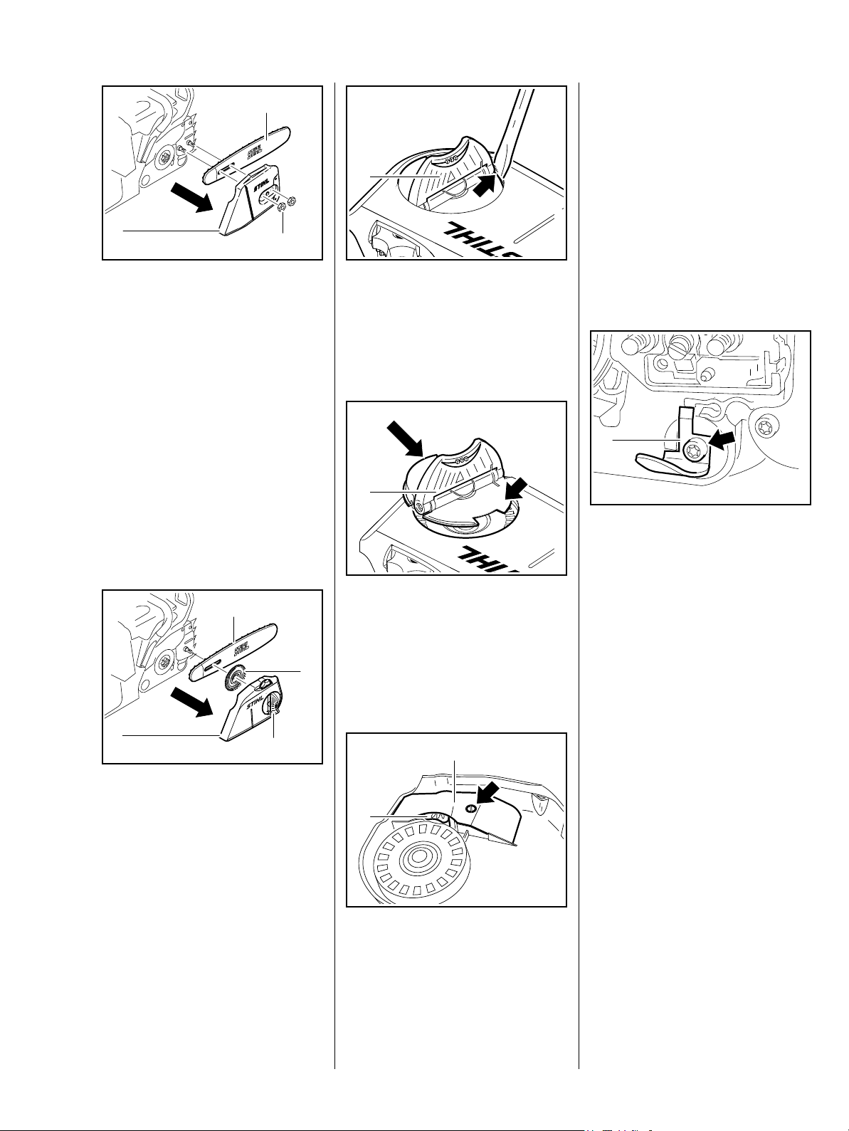
5. Cutting Attachment
3
2
1
Wear gloves to protect your hands
from injury.
: Unscrew the hex nuts (1).
: Remove the chain sprocket
cover (2).
: Remove the guide bar (3) with
chain.
– Reassemble in the reverse
sequence.
1
165RA002 TG
: Carefully pry the wing nut (1) out
of the sprocket cover (arrow).
– Check the wing nut (1) and
replace if necessary
1
When installing the adjusting wheel,
make sure its teeth point
inboard.
– Reassemble in the reverse
sequence.
5.1 Chain Catcher
165RA469 TG
– Remove the sprocket cover and
cutting attachment, b 5
1
165RA247 TG
Versions with Quick Chain
Tensioner
4
3
2
1
Wear gloves to protect your hands
from injury.
: Swing the wing nut (1) upright
and loosen it counterclockwise.
: Remove the sprocket cover (2)
and tensioning gear (3) with
guide bar (4).
– Swing the wing nut (1) upright.
: Push the wing nut (1), thin side
first (see arrow), into the opening
and press it down until it snaps
into positon.
165RA464 TG
1
2
: Take out the screw (arrow).
: Take out the screw (arrow) and
remove the chain catcher (1).
165RA007 TG
– Reassemble in the reverse
sequence.
– Tightening torques, b 3.5
165RA455 TG
– Reassemble in the reverse
sequence.
– Remove the cover plate (1) and
adjusting wheel (2).
19MS 240, MS 260, MS 260 C
Page 21
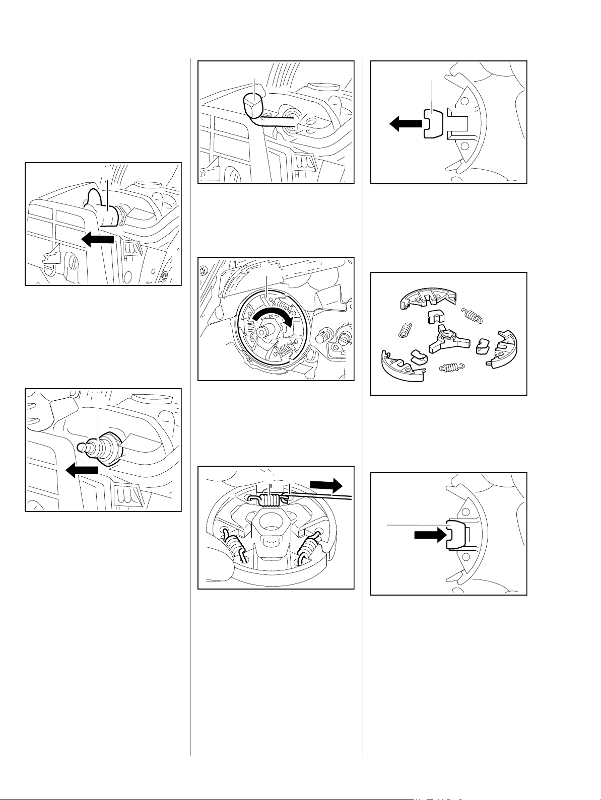
6. Clutch
– Troubleshooting, b 4.1
– Remove the sprocket cover and
cutting attachment, b 5
– Remove the clutch drum, b 6.1
1
– Remove the air filter, b 14.1
– Remove the shroud, b 8.4
: Pull boot (1) off the spark plug.
1
: Push the locking strip (1)
0000 893 5903 into the cylinder
so that "OBEN-TOP" is visible.
1
165RA009 TG
1
165RA011 TG
– Pull the clutch shoes off the
carrier.
: Remove the retainers (1).
165RA014 TG
1
: Unscrew the spark plug (1).
: Unscrew the clutch (1).
Note that the clutch has a left-hand
thread.
2
1
165RA010 TG
Disassembling
: Use hook (2) 5910 890 2800 to
remove the clutch springs (1).
165RA012 TG
– Clean all parts..
– Replace any damaged parts.
1
165RA013 TG
: Fit the retainers (1).
165RA015 TG
165RA016 TG
20 MS 240, MS 260, MS 260 C
Page 22
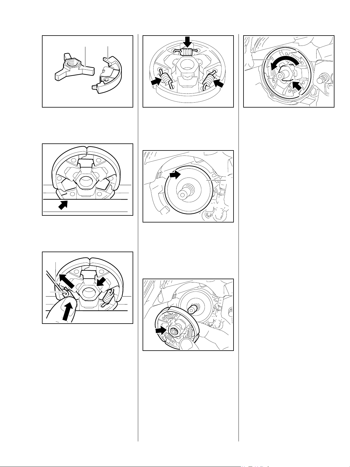
21
1
: Fit the clutch shoes (2) over the
arms (2).
: Clamp the clutch in a vise
(arrow).
2
165RA017 TG
: Check the clutch – all springs
(arrows) must be properly
attached.
TOP
165RA018 TG
– Make sure the washer (1) is in
place.
Installed position is correct when
"TOP" (arrow) faces outwards.
165RA020 TG
: Screw the clutch (1) on to the
crankshaft stub and tighten down
the hexagon (arrow) firmly – lefthand thread.
– Tightening torques, b 3.5
– Remove the locking strip from the
cylinder.
1
– Reassemble all other parts in the
reverse sequence.
165RA021 TG
165RA023 TG
1
Attach the springs on the side with
the raised hexagon (arrow).
: Attach one end of each spring (1)
to the clutch shoes.
: Use the hook (2) 5910 890 2800
to attach the other ends of the
springs and press them firmly into
the clutch shoes.
TOP
165RA470 TG
165RA022 TG
: Position the clutch on the
crankshaft stub so that the raised
hexagon (arrow) faces outwards.
21MS 240, MS 260, MS 260 C
Page 23
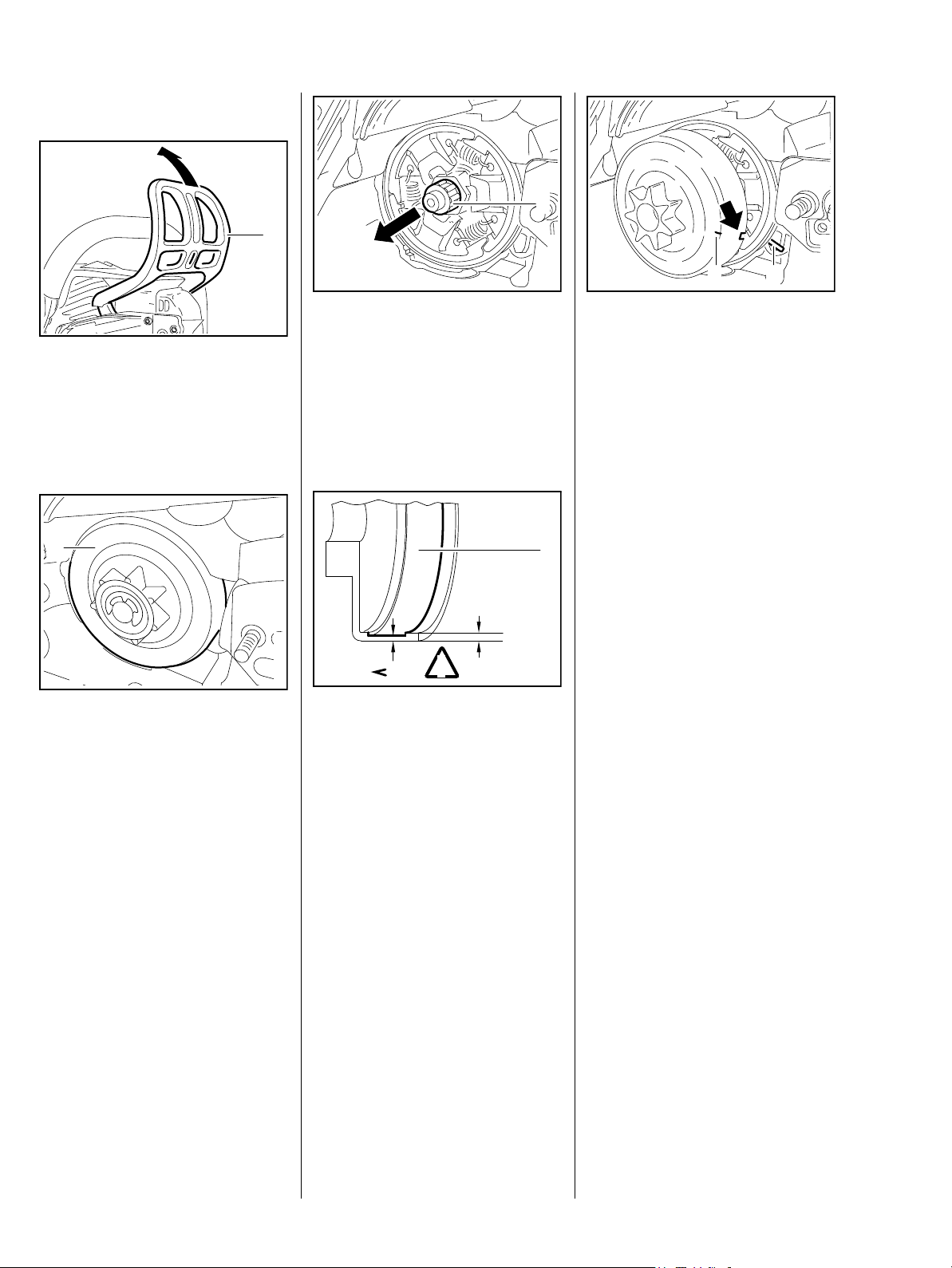
6.1 Clutch Drum
1
1
– Remove the sprocket cover and
cutting attachment, b 5
: Pull the hand guard (1) towards
the handlebar.
1
Remove and install the clutch drum
(1), see instruction manual.
: Pull off the needle cage (1).
165RA024 TG
– Clean the needle cage (1) and
crankshaft stub, b 17
– Lubricate the needle cage (1) and
crankshaft stub, b 17
165RA377 TG
80%
!
– Inspect the clutch drum (1) for
signs of wear.
100%
165RA411 TG
2
The notch (arrow) in the clutch drum
must engage the worm gear's driver
(1).
Use the mark (2) for orientation.
– Apply thin coating of oil to outside
diameter of clutch drum and the
brake band.
– Reassemble all other parts in the
reverse sequence.
1
165RA029 TG
1
165RA415 TG
If there are signs of serious wear on
the inside diameter of the clutch
drum (1), check the remaining wall
thickness. If it is less than about
80% of the original thickness, install
a new clutch drum.
22 MS 240, MS 260, MS 260 C
Page 24
7. Chain Brake
7.1 Checking Operation
The chain brake is one of the most
important safety devices on the
chain saw. Its efficiency is
measured in terms of the chain
braking time, i.e. the time that
elapses between activating the
brake and the saw chain coming to
a complete standstill.
Contamination (with chain oil, chips,
fine particles of abrasion, etc.) and
smoothing of the friction surfaces of
the brake band and clutch drum
impair the coefficient of friction,
which prolongs the braking time. A
fatigued or stretched brake spring
has the same negative effect.
– Start the engine.
– With the chain brake activated
(locked), open the throttle wide
for a brief period (max. 3
seconds) – the chain must not
rotate.
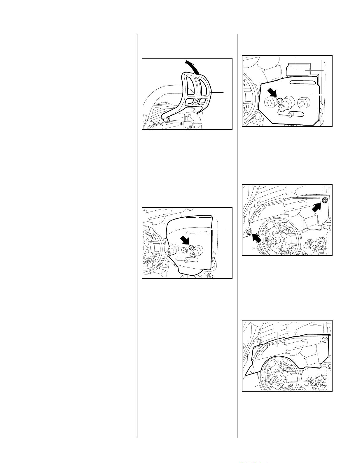
7.2 Removing and Installing the Brake Band
1
: Disengage the chain brake by
pulling the hand guard (1)
towards the front handle.
The brake band is no longer under
tension.
– Remove the clutch drum, b 6.1
Versions with Quick Chain
Tensioner
165RA024 TG
: Take out the screw (arrow) and
remove the side plate (1).
: Remove the upper bumper strip
(2).
2
1
165RA037 TG
– With the chain brake released,
open the throttle wide and
activate the brake manually – the
chain must come to an abrupt
stop.
The braking time is in order if
deceleration of the saw chain (less
than a second) is imperceptible to
the eye.
The chain must come to a standstill
in less than a second.
If the chain brake does not operate
properly, refer to troubleshooting,
b 4.2.
1
– Troubleshooting, b 4.2
– Remove the sprocket cover and
cutting attachment, b 5
: Take out the screw (arrow) and
remove the side plate (1).
: Take out the screws (arrows).
165RA471 TG
On versions with handle heating
– Remove the ground wire,
b 15.4.1.
1
165RA038 TG
165RA039 TG
: Remove the cover (1).
23MS 240, MS 260, MS 260 C
Page 25
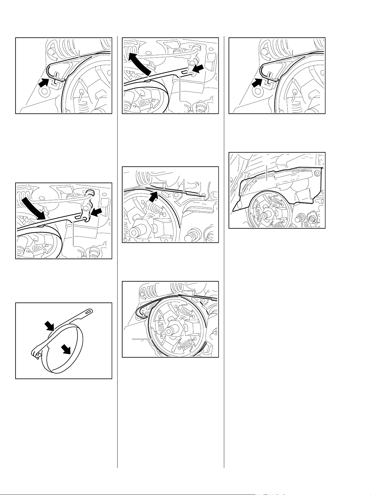
1
1
: Pry the brake band (1) out of its
seat (arrow).
– Remove the brake band (1).
Do not over-stretch the brake band.
1
: Turn the brake band (1) to one
side and disconnect it from the
brake lever (arrow).
165RA040 TG
1
: Hold the brake band (1)
sideways, attach it to the brake
lever (arrow) and then swing it in
the direction of its seat.
1
: Position the brake band (1) it the
165RA042 TG165RA043 TG
guide (arrow) first.
165RA044 TG
: Push the brake band (1) into its
guide (arrow) as far as stop.
1
: Place the cover (1) in position.
165RA045 TG
– On versions with handle heating,
fit the ground wire, b 15.4.1
– Insert screws and tighten them
down firmly.
165RA040 TG
165RA039 TG
– Tightening torques, b 3.5
– On versions with quick chain
tensioner, install the upper
bumper strip.
1
– Install the clutch drum,
165RA041 TG
b 6.1
: Push the brake band (1) into its
seat.
Install a new brake band if there are
noticeable signs of wear (large
areas on inside diameter and/or
parts of outside diameter – arrows)
and its remaining thickness is less
than 0.6 mm.
24 MS 240, MS 260, MS 260 C
– Check operation.
– Reassemble all other parts in the
reverse sequence.
Page 26
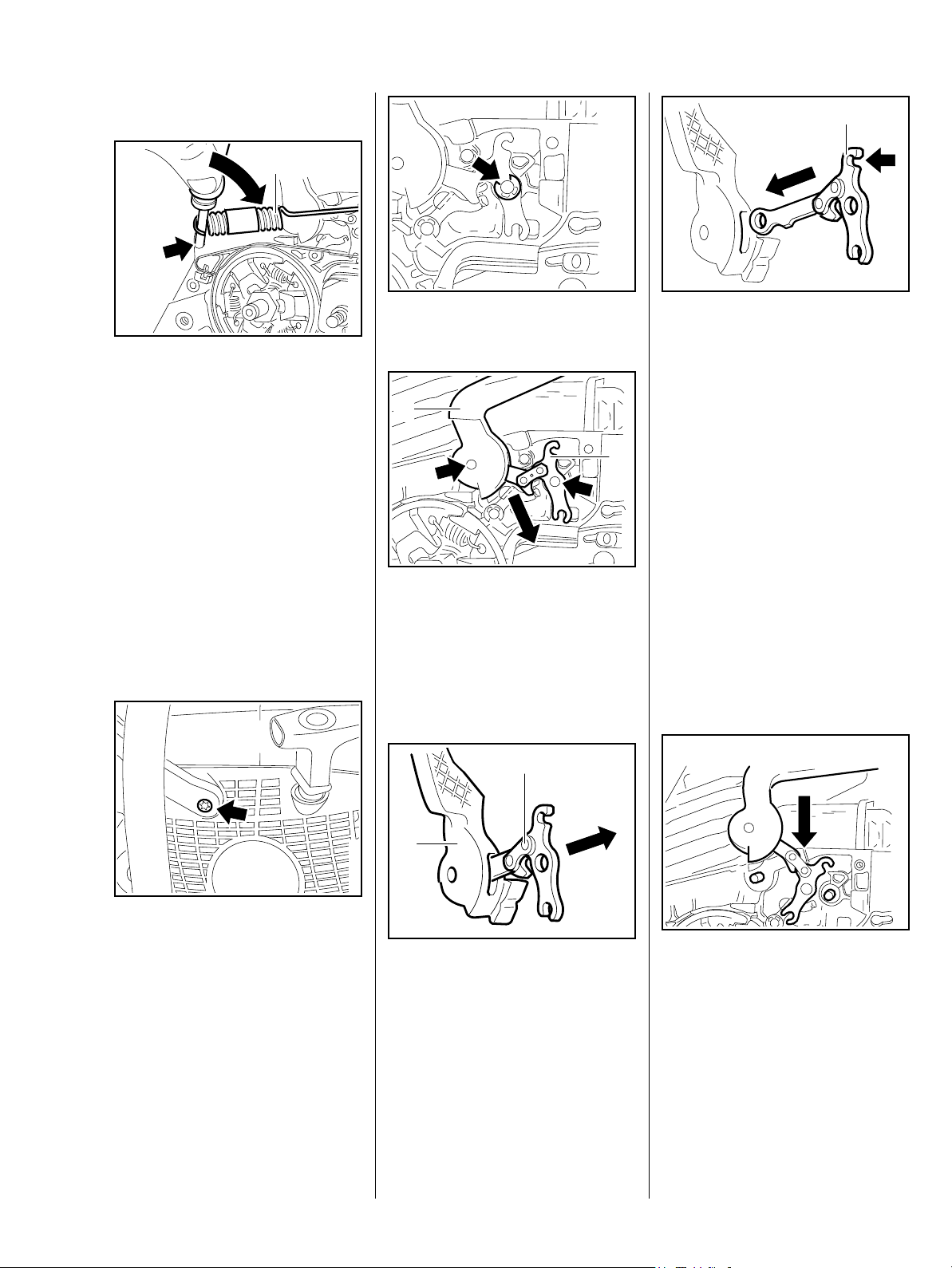
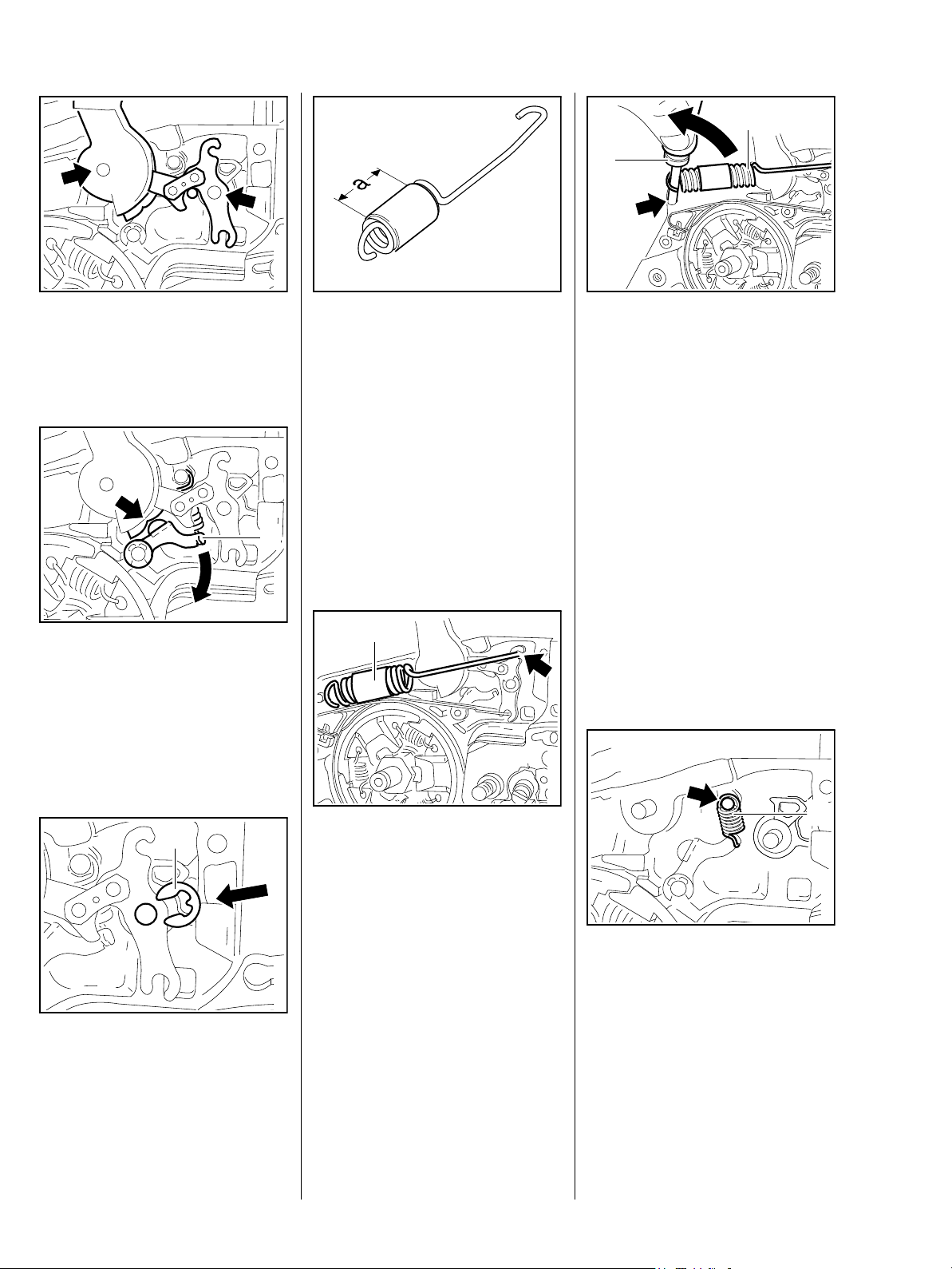
7.3 Brake Lever
1
1
– Troubleshooting, b 4.2
– Push the hand guard towards the
guide bar.
The brake spring (1) is now relaxed.
– Remove the brake band, b 7.2
: Use the assembly tool 117 890
0900 to disconnect the brake
spring (1) from the anchor pin
(arrow).
– Disconnect the brake spring (1)
from the brake lever.
: Remove the E-clip (arrow).
165RA047 TG
1
: Pull the hand guard (1) and brake
lever (2) off the pivot pins
(arrows) together.
– Remove the hand guard (1) and
brake lever (2).
165RA049 TG
– Inspect the pivot pins and replace
if necessary,
b 7.5
– Inspect the cam lever and
replace if necessary, b 7.4
Clean all disassembled parts with a
2
little standard commercial solventbased degreasant containing no
chlorinated or halogenated
hydrocarbons.
165RA050 TG
– Hold the brake lever (1) so that
the brake spring attachment point
(arrow) is at the top.
: Push the brake lever (1) into the
hand guard recess and line up
the holes.
165RA052 TG
: Take out the screw (arrow).
2
1
165RA048 TG
: Take the brake lever (2) out of the
hand guard (1).
– Inspect the brake lever (2) and
hand guard (1) and replace if
necessary.
165RA051 TG
: Push the hand guard with brake
lever over the machine until it is
positioned against the pivot pin.
165RA472 TG
25MS 240, MS 260, MS 260 C
Page 27
1
2
: Lift the bearing boss of the hand
guard and the brake lever a little
and position them over the pivot
pins (arrows).
1
: Turn the cam lever (1) to one side
until the cam of the hand guard
(arrow) slips passed it.
– Push the hand guard bearing
boss and the brake lever on to
the pivot pins.
165RA054 TG165RA055 TG
: The turns of brake spring must be
tightly against one another in the
relaxed condition. If this is not the
case, replace the brake spring.
Check the correct position of the
protective hose – it must be
centered in the spring.
a = 20 mm
If the groove in the brake spring
anchor pin is worn, install a new pin,
b 7.5
1
165RA057 TG
: Use the assembly tool (2)
1117 890 0900 to attach the
brake spring (1) to the anchor pin
(arrow).
– Reassemble all other parts in the
reverse sequence.
– Tightening torques, b 3.5
– Lubricate the brake lever, b 17
7.4 Cam Lever
The cam lever defines the locked
position of the hand guard.
– Remove the brake lever, b 7.3
165RA059 TG
165RA058 TG
1
1
: Fit the E-clip (1).
26 MS 240, MS 260, MS 260 C
: Attach the brake spring (1) to the
brake lever (arrow).
: Disconnect the spring (1) from
the anchor pin (arrow).
165RA056 TG
165RA060 TG
Page 28
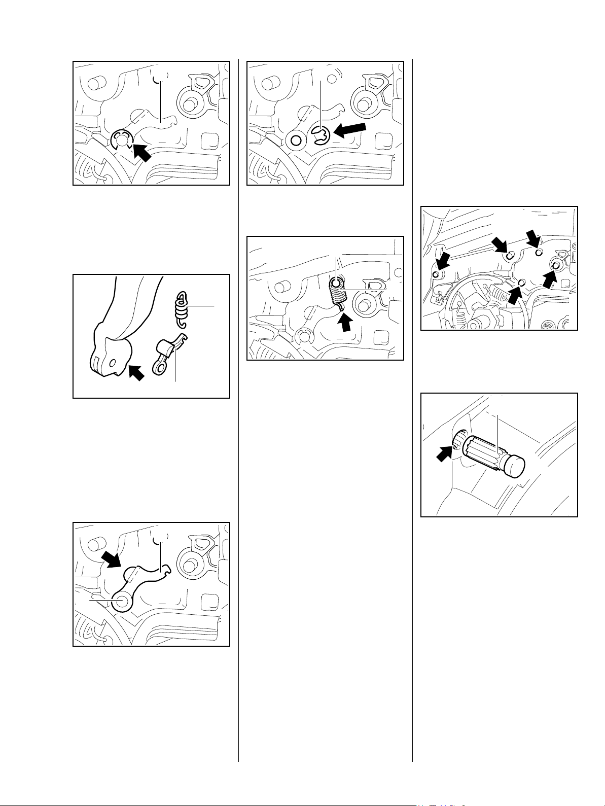
1
1
The anchor pins secure the springs.
Worn pins must be replaced
– the springs may otherwise
become detached and pop out.
All parts have been removed from
the pins in the following illustrations
7.5 Pins
165RA061 TG
for greater clarity.
165RA064 TG
: Remove the E-clip (arrow).
– Pull the cam lever (1) off the pivot
pin.
2
1
– Check the cam lever (1) and
spring (2) and replace if
necessary.
– Check the condition of the cam
contour (arrow) and replace the
hand guard if necessary.
: Fit the E-clip (1).
2
: Attach the spring (1) to the cam
lever so that the open side of the
165RA062 TG
spring hook (Pfeil) points toward
the housing.
If the groove in the spring's anchor
pin is worn, install a new pin, b 7.5
– Attach the spring (1) to the anchir
pin (2).
1
: Use a suitable tool to pull out the
165RA065 TG
pins (arrows).
1
165RA066 TG
1
2
– Position the cam lever (1) so that
its cam (arow) faces the cam on
the hand guard.
: Push the cam lever (1) on to the
pivot pin (2).
The cam lever is not yet under
tension – the spring may become
detached.
– Reassemble all other parts in the
reverse sequence.
– Tightening torques, b 3.5
– Lubricate the cam lever, b 17
165RA063 TG
165RA067 TG
– Before installing the new pin (1),
coat its knurled shank with
Loctite, b 17
: Position the new pin (1) in the
bore (arrow) so that the knurling
on the pin meshes with the
existing knurling in the bore.
Turn the pin (1) back and forth as
necessary.
27MS 240, MS 260, MS 260 C
Page 29
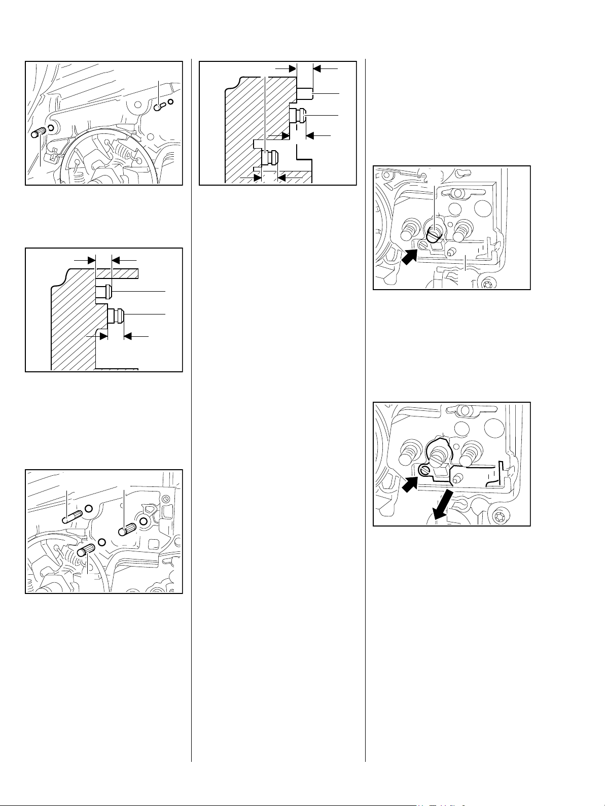
2
4
a
7.6 Side Chain Tensioner
– Remove the sprocket cover and
3
cutting attachment, b 5
5
c
– Troubleshooting, b 4.2
1
: Drive home the pins (1 and 2) as
shown in the illustrations.
a
1
2
b
: Carefully tap home the pins to
obtain the following dimensions:
Pin (1) a = 4.3 – 4.7 mm
Pin (2) b =. 3.0 – 3.4 mm
165RA068 TG
: Carefully tap home the pins to
obtain the following dimensions:
Pin (3) a = 4.3 – 4.7 mm
Pin (4) b = 3.0 – 3.4 mm
Pin (5) = 3.0 – 3.4 mm
The pins must be driven home
squarely.
– Reassemble all other parts in the
reverse sequence.
– Tightening torques, b 3.5
165RA069 TG165RA070 TG
– Lubricate the brake and cam
levers, b 17
b
165RA378 TG
2
1
– Remove the side plate.
: Turn the spur gear (2) clockwise
until the tensioner slide (1) butts
against the right-hand end and
the screw (arrow) is visible.
165RA459 TG
3
4
: Drive home pins (3, 4 and 5) as
specified below.
28 MS 240, MS 260, MS 260 C
5
: Take out the screw (arrow).
– Pull out the tensioner side with
adjusting screw, thrust pad and
spur gear.
165RA460 TG
Page 30
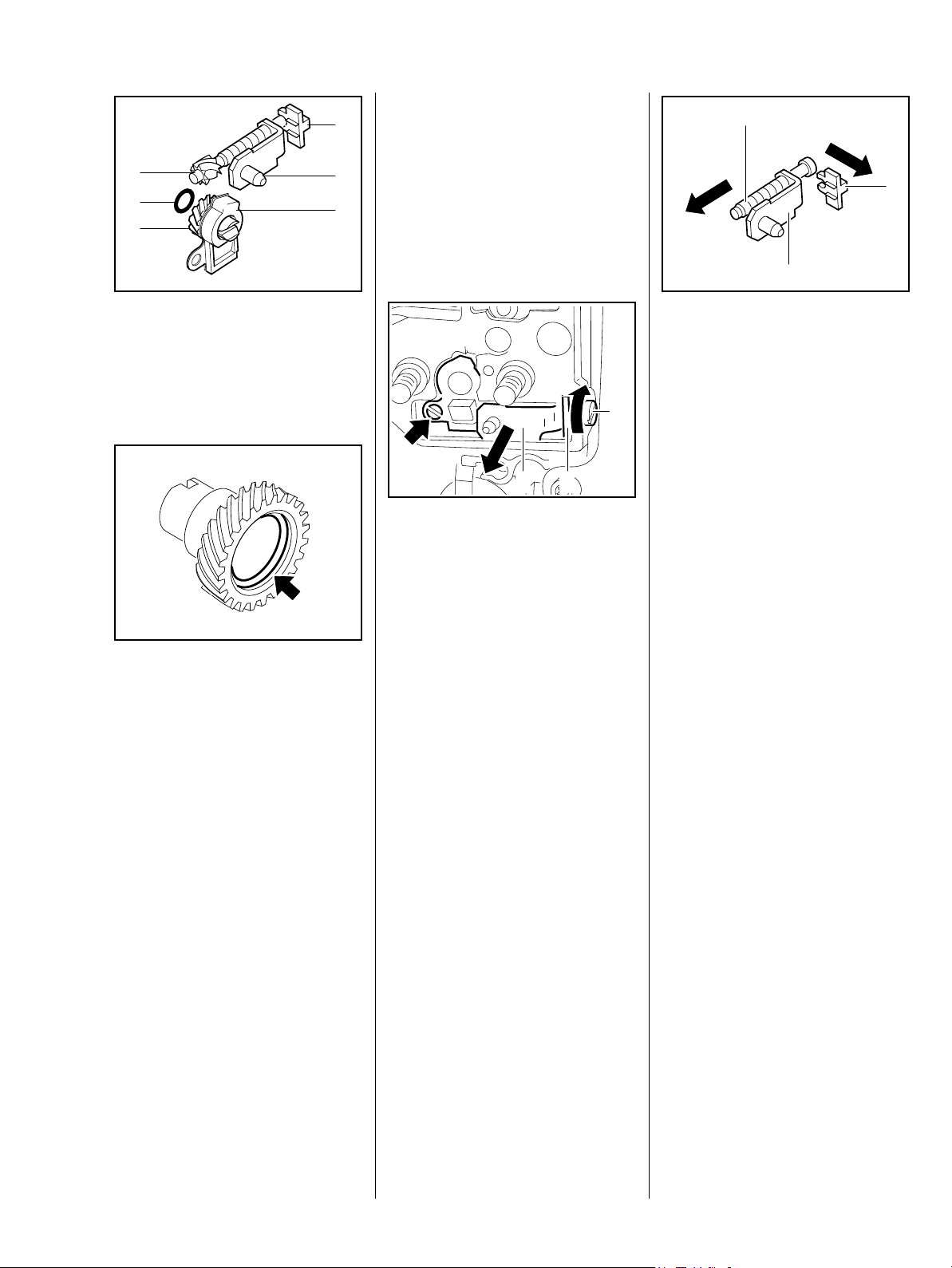
7.6.1 Front Chain Tensioner
3
– Remove the sprocket cover and
2
6
1
4
cutting attachment, b 5
– Troubleshooting, b 4.2
2
1
5
– Remove the side plate, b 7.2
: Inspect the thrust pad (1),
adjusting screw (2), tensioner
slide (3), cover plate (4), spur
gear (5) and O-ring (6) and
replace as necessary.
: Fit the O-ring in the spur gear
recess (arrow).
– Clean all disassembled parts with
a little standard commercial
solvent-based degreasant
containing no chlorinated or
halogenated hydrocarbons.
Always replace the adjusting screw
and spur gear as a matching pair.
165RA461 TG
2
: Turn the adjusting screw (1)
clockwise until the tensioner slide
(2) butts against the right-hand
end and the screw (arrow) is
visible.
165RA458 TG
: Pull out the tensioner slide (2)
with thrust pad (3).
3
: Pull off the thrust pad (1) and
unscrew the adjusting screw (2)
from the tensioner slide (3).
– Check the individual parts and
1
3
replace if necessary.
– Reassemble in the reverse
sequence.
165RA465 TG
– Clean all disassembled parts with
a little standard commercial
solvent-based degreasant
containing no chlorinated or
halogenated hydrocarbons.
– Lubricate thread with STIHL
multipurpose grease, b 17
– Reassemble all other parts in the
reverse sequence.
7.6.2 Quick Chain Tensioner
The quick chain tensioner is
installed in the chain sprocket cover.
See chapter on cutting attachment,
b 5
165RA463 TG
– Lubricate the threads, gears and
O-ring with STIHL multipurpose
grease, b 17
– Reassemble in the reverse
sequence.
29MS 240, MS 260, MS 260 C
Page 31

7.7 Bar Mounting Studs
Versions with Quick Chain
Tensioner
1
– Remove the sprocket cover and
cutting attachment, b 5
– Remove the side plate, b 7.6
: Push stud puller 5910 893 0501
(1) over the collar studs (arrows)
as far as it will go and unscrew
the studs counterclockwise.
: Before installing, coat threads
(arrow) of collar studs with
Loctite, b 17
165RA081 TG
1
– Remove the sprocket cover and
cutting attachment, b 5
– Remove the side plate, b 7.6
: Push stud puller 5910 893 0501
(1) over the collar stud (arrow) as
far as it will go and unscrew the
stud counterclockwise.
165RA082 TG
: Before installing, coat thread
(arrow) of collar stud with Loctite,
b 17
165RA083 TG
165RA087 TG
– Fit collar studs and tighten them
down firmly.
– Tightening torques, b 3.5
– Reassemble all other parts in the
reverse sequence.
– Fit collar stud and tighten it down
firmly.
– Tightening torques, b 3.5
Reassemble all other parts in the
reverse sequence.
30 MS 240, MS 260, MS 260 C
Page 32

8. Engine
8.1 Muffler / Spark Arresting Screen
Always check and, if necessary,
repair the fuel system, carburetor,
air filter and ignition system before
looking for faults on the engine.
– Troubleshooting, b 4
1
: Take out the screws (arrows).
2
: Remove the heat shield (1), if
fitted.
: Remove the gasket (2).
Spark arresting screen
(if fitted)
165RA084 TG
1
1
165RA086 TG
: Check the reflector foil (1), if
fitted, and replace if necessary
1
1
165RA457 TG
– Remove the exhaust casing (1).
1
: Take out the screws (arrows).
– Remove the muffler (1), check
and replace if necessary.
: Take out the screw (1).
: Pull out the spark arresting
screen (2).
– Clean the spark arresting screen
165RA085 TG
(2) or replace if necessary.
– Reassemble in the reverse
sequence.
2
: Position the reflector foil (1)
aganst the edges (arrows).
165RA473 TG
– Hold the machine upright.
: Inspect and clean the sealing
faces (arrows) and remove any
gasket residue.
165RA090 TG
165RA091 TG
31MS 240, MS 260, MS 260 C
Page 33

1
2
2
1
1
: Place the heat shield (1) in
position (if fitted) and use the
indentations (arrows) to line it up
on the sealing face of the cylinder
exhaust port.
1
: If the heat shield is fitted, position
the gasket (1) between the
projections (arrows)
– the gasket is now held in
position.
– Versions without heat shield:
Place gasket (1) on the cylinder
exhaust port, the raised edge
must face the port and the holes
must be in alignment.
165RA092 TG
– Carefully place the muffler (1) in
position.
: Line up the screws (arrows) and
check the position of the gasket.
: Insert screws (2) to hold the
muffler in position.
: Insert screws (arrows) and
tighten them down firmly.
165RA093 TG
1
– Remove the screws used to hold
the muffler in position.
: Attach tab (arrow) of the exhaust
casing (1) to the muffler first and
then swing it into position.
165RA094 TG
: Insert screws (arrows) and
tighten them down firmly.
– Tightening torques, b 3.5
8.2 Leakage Test
Defective oil seals and gaskets or
cracks in castings are the usual
causes of leaks. Such faults allow
supplementary air to enter the
engine and upset the fuel-air
mixture.
This makes adjustment of the
prescribed idle speed difficult, if not
impossible.
Moreover, the transition from idle
speed to part or full throttle is not
smooth.
165RA095 TG
Always perform the vacuum test
first and then the pressure test.
The engine can be checked
thoroughly for leaks with the pump
0000 850 1300.
165RA084 TG
32 MS 240, MS 260, MS 260 C
Page 34

8.2.1 Preparations
1
2
1
2
1
– Remove the shroud, b 8.4
– Set the piston to top dead center.
This can be checked through the
spark plug hole.
– Remove the decompression
valve, b 8.9
: Fit the plug (1) 1122 025 2200
and tighten it firmly.
: Fit the spark plug (2) and tighten
it down firmly.
– Tightening torques, b 3.5
: Fit the sealing plate (1)
165RA474 TG
0000 855 8106 between the
cylinder exhaust port and heat
shield (if fitted) and tighten down
the screws moderately.
The sealing plate must completely
fill the space between the two
screws.
– Remove the carburetor, b 14.2
1
165RA099 TG
– Pin (1) must be in the test flange
1128 850 4200
– it seals the impulse hose.
: Make sure that the pin (1) is in
hole "2" (arrow).
1
2
– Fit the test flange 1128 850
4200 (1).
1
165RA475 TG
165RA493 TG165RA494 TG
– Remove the muffler exhaust
casing, b 8.1
: Loosen the screws (arrows).
1
: Check that the sleeve (2) and
washer (1) are in place.
165RA085 TG
165RA100 TG
: When pushing the test flange (1)
into position, make sure the pin
engages the impulse hose
(arrow).
: Fit the nuts (arrows) and tighten
them down firmly.
33MS 240, MS 260, MS 260 C
Page 35

8.2.2 Vacuum Test
Oil seals tend to fail when subjected
to a vacuum, i.e. the sealing lip lifts
away from the crankshaft during the
piston's induction stroke because
there is no internal counterpressure.
A test can be carried out with pump
0000 850 1300 to detect this kind of
fault.
1
If the vacuum reading remains
constant, or rises to no more than
0.3 bar within 20 seconds, it can be
assumed that the oil seals are in
good condition.
However, if the pressure continues
to rise (reduced vacuum in the
engine),
the oil seals
must be replaced, b 8.3.
– After finishing the test, push the
ring (1) to the right to vent the
pump.
– Continue with pressure test,
b 8.2.3
8.2.3 Pressure Test
165RA104 TG
1
1
: Push ring (1) to the right.
: Operate the lever (2) until the
pressure gauge (arrow) indicates
a pressure of 0.5 bar. If this
pressure remains constant for at
least 20 seconds, the crankcase
is airtight.
– If the pressure drops, the leak
must be located and the faulty
part replaced.
2
165RA003 TG
: Connect suction hose (1) of
pump 0000 850 1300 to
nipple (arrow).
1
: Push ring (1) to the left.
: Operate the lever (2) until the
pressure gauge (arrow) indicates
a vacuum of 0.5 bar.
Carry out the same preparations as
for the vacuum test, b 8.2.2
2
– Always carry out the vacuum test,
before the pressure test, b 8.2.2
: Connect pressure hose (1) of
165RA476 TG
pump 0000 850 1300 to nipple
(arrow).
To find the leak, coat the suspect
area with oil and pressurize the
crankcase again. Bubbles will
appear if a leak exists.
– After finishing the test, push the
ring (1) to the left to vent the
165RA104 TG
pump – disconnect the hose.
– Remove the test flange.
– Install the carburetor, b 14.2
– Loosen the muffler and pull out
the sealing plate.
– Tighten down the muffler firmly.
– Reassemble all other parts in the
reverse sequence.
– Tightening torques, b 3.5
34 MS 240, MS 260, MS 260 C
Page 36

8.3 Oil Seals
– Clamp the puller arms.
It is not necessary to disassemble
the engine to replace the oil seals.
Ignition side
– Remove the fan housing,
b 10.2
– Remove the flywheel, b 9.5
– Remove the generator, b 15.7
Versions with handle hearing
1
: Remove the Woodruff key (1).
– Pull out the oil seal.
Take care not to damage the
crankshaft stub.
– Clean the sealing face with a little
standard solvent-based
degreasant containing no
chlorinated or halogenated
hydrocarbons.
– Lubricate sealing lips of new oil
seal with grease, b 17
1
165RA106 TG
– Apply a thin coating of sealant to
the outside diameter of the oil
seal (1), b 17
1
: Install the Woodruff key (1) – its
straight side (arrow) must be in
line with the taper.
– Reassemble all other parts in the
reverse sequence.
Clutch side
– Remove the sprocket cover and
2
cutting attachment, b 5
– Remove the clutch, b 6
– Remove the oil pump,
adjustable, b 13.5,
165RA108 TG
non-adjustable, b 13.4
2
165RA109 TG
1
– Free off the oil seal in its seat by
tapping it with a suitable tube or a
punch.
: Apply puller (1) 5910 890 4400
with No. 3.1 jaws 0000 893 3706.
– Slip the oil seal (1), open side
facing the crankcase, over the
crankshaft stub.
: Use press sleeve (2)
1121 893 2400 to install the oil
seal (1).
165RA107 TG
The seating face must be flat and
free from burrs.
– Wait about one minute, then
rotate the crankshaft several
times.
Clean the crankshaft with a little
standard commercial solvent-based
degreasant containing no
chlorinated or halogenated
hydrocarbons.
1
165RA110 TG
: Remove the washer (1) and
ring (2).
35MS 240, MS 260, MS 260 C
Page 37

– Slip the oil seal (2), open side
facing the crankcase, over the
1
installing sleeve.
– Remove the installing sleeve (1).
8.4 Removing and Installing the Shroud
– Free off the oil seal in its seat by
tapping it with a suitable tube or a
punch.
: Apply puller (1) 5910 890 4400
with No. 3.1 jaws 0000 893 3706.
– Clamp the puller arms.
– Pull out the oil seal.
Take care not to damage the
crankshaft stub.
– Clean the sealing face with a little
standard solvent-based
degreasant containing no
chlorinated or halogenated
hydrocarbons.
– Lubricate sealing lips of new oil
seal with grease, b 17
165RA111 TG
2
1
: Use press sleeve (2) 1120 893
2400 to install the oil seal (1).
2
1
– Wait about one minute, then
rotate the crankshaft several
times.
1
: Unscrew the slotted nut (arrow).
165RA113 TG
: Remove the shroud (1) over the
decompression valve (2).
165RA114 TG
: Pull off the stop buffer (1), check
it and replace if necessary.
– Reassemble in the reverse
sequence.
2
165RA115 TG
1
165RA116 TG
: Fit the washer (1) and ring (2).
– Reassemble all other parts in the
1
reverse sequence.
2
165RA477 TG
: Fit the installing sleeve (1) 1118
893 4602.
– Apply a thin coating of sealant to
the outside diameter of the oil
seal (2), b 17
: Push out the slotted nut (1) with
insulator.
36 MS 240, MS 260, MS 260 C
1
165RA004 TG
Page 38

1
2
: Pull the insulator (1) off the
slotted nut (2).
– Check the individual parts and
replace if necessary.
Versions with decompression
valve
165RA005 TG
: Bond the new reflector foil in
position along the ribs (arrows).
8.5 Cylinder
Before removing the piston, decide
whether or not the crankshaft has to
be removed as well.
1
Cylinder installed
To remove the flywheel and clutch,
the.crankshaft has to be blocked by
inserting the locking strip in the
spark plug hole.
Cylinder removed
165RA008 TG
To remove the flywheel and clutch,
the crankshaft has to be blocked by
resting the piston on the wooden
assembly block.
– Reassemble in the reverse
sequence.
1
: Push the slotted nut (1) with
insulator into the bore until it
engages in position.
1
– Check the cap (1), if fitted, and
replace if necessary
If a new shroud is fitted, the cap (1)
must be removed.
165RA456 TG
: Fit the shroud (1). Push the lugs
(2) into the holes (arrows).
Make sure the stud is located
against the slotted nut.
– Screw home the slotted nut as far
as stop.
1
2
– Remove the shroud, b 8.4
– Pull off the boot and unscrew the
spark plug, b 6
– Remove the fan housing,
b 10.2
– Remove the carburetor, b 14.2
– Push the manifold out of the tank
housing,
b 14.6.1
– Remove the muffler, b 8.1
– Remove the decompression
165RA025 TG
valve, b 8.9
– Remove the handlebar, b 11.5.
On versions with handle heating,
take out the screws and swing
the handlebar to one side,
b 11.6
– Inspect the reflector foil (1) and
replace it if it is damaged.
– Reassemble all other parts in the
reverse sequence.
165RA457 TG
37MS 240, MS 260, MS 260 C
Page 39

Always use a new cylinder gasket
when re-installing the cylinder.
1
1
: Pull off the stop buffer (1).
1
: Pull the impulse hose (1) off the
nipple (arrow).
165RA116 TG
: Carefully lift the cylinder (1) away.
Do not use pointed or sharp-edged
tools for this job.
165RA387 TG
: Remove the cylinder gasket (1).
165RA495 TG
1
165RA032 TG
– Line up the cylinder gasket (1) so
that the tabs (arrow) point toward
the carburetor and cutting
attachment.
: Place the cylinder gasket (1) in
position.
1
165RA030 TG
2
1
: Take out the four cylinder base
screws through the holes
(arrows) in the cylinder.
165RA027 TG
– Inspect and clean the sealing
face (arrow), b 17
The sealing face must be in perfect
condition. Always replace
components with damaged sealing
faces, b 4.7.
– Inspect the intake manifold (2)
and replace it if necessary – even
very minor damage can result in
engine running problems, b 4.7
: Loosen the hose clamp (1) and
165RA031 TG
pull off the manifold (2).
165RA033 TG
38 MS 240, MS 260, MS 260 C
Page 40

: Tighten the screw until the gap
"a" between the two ends of the
hose clamp is about 5 to 6 mm.
1
1
– Push the manifold (1) on to the
intake stub.
: Line up the manifold (1)
– the tab must be pisitioned as
shown in the illustration (arrow).
– Position the hose clamp so that
the screw head (arrow) points
toward the clutch side.
165RA034 TG
: Inspect and clean the sealing
face (arrow) and remove any
gasket residue.
– Check the sealing faces on the
cylinder intake and exhaust ports.
The sealing faces must be in perfect
condition. If the sealing faces are
damaged, install a new cylinder.
165RA071 TG165RA035 TG
1
– Lubricate the piston, piston rings
and cylinder wall with oil, b 17
: Use the clamping strap (1)
165RA072 TG165RA073 TG
0000 893 2600 to compress the
rings around the piston.
– Check correct installed position
of rings, b 8.8
Apply the clamping strap (1) so that
the piston rings do not project
beyond the cylinder wall.
165RA074 TG
: Push the hose clamp on to the
manifold.
a
– Turn the hose clamp until the
screw head is below the lower
cylinder fin (arrow).
: Slide the wooden assembly block
(1) 1108 893 4800 between the
piston and crankcase.
165RA079 TG
: Align the cylinder so that the
intake port (arrow) points toward
the rear handle.
While sliding the cylinder over the
piston, hold the clamping strap
tightly around the piston so that the
rings do not project – they might
otherwise break.
: Slide the cylinder over the piston,
the clamping strap moves
downwards at the same time.
39MS 240, MS 260, MS 260 C
Page 41

1
remove the generator, b 15.7
– Drain the fuel and oil tanks, b 1
– On versions with handle heating,
1
2
: Remove the clamping strap (1)
and wooden assembly block (2).
Make sure the cylinder gasket is
properly seated.
– Push the cylinder fully home.
: Insert the screws (arrows) to hold
the cylinder and gasket in
position..
165RA080 TG
– Lift the tank housing a little.
: Push the impulse hose (1) on to
the nipple (arrow).
– Reassemble all other parts in the
reverse sequence.
8.6 Crankshaft
8.6.1 Removing and Installing
– Remove the sprocket cover and
cutting attachment, b 5
– Remove the adjustable oil pump,
165RA027 TG
b 13.5
– Remove the non-adjustable oil
pump, b 13.4
– Remove the brake band, b 7.2
– Remove the tank housing,
b 14.8.3
Always install new bearings and oil
seals after removing the crankshaft,
165RA096 TG
b 8.6.2 and b 8.3
Removing – clutch side
Use the tools in the service tool set
5910 007 2200 for removing and
installing.
2
1
: Remove the washer (1) and ring
(2).
165RA110 TG
– Tighten down the screws in an
– Remove the brake lever, b 7.3
alternate pattern.
– Remove the handlebar, b 11.5
– Tightening torques, b 3.5
. Remove the handleber with
handle heating, b 11. 6
– Remove the cylinder, b 8.5
– Remove the piston, b 8.7
: Take out the screws (arrows).
– Remove the flywheel, b 9.5
40 MS 240, MS 260, MS 260 C
165RA097 TG
Page 42

Versions with Quick Chain
Tensioner
Removing – ignition side
Use the tools in the service tool set
5910 007 2200 for removing and
installing.
: Use a 4 mm diameter drift to drive
out the cylindrical pin at the chain
tensioner side.
1
: The tensioner slide (1) must butt
against the thrust pad (arrow).
165RA117 TG
2
1
: Push the service tool (1)
5910 890 2205 over the collar
screw, fit the nut and tighten it
firmly.
: Turn the spindle (2) clockwise
until the crankshaft stub is
pushed out of the ball bearing.
This operation releases the clutch
side of the crankcase and separates
the two halves.
165RA078 TG
– Install new ball bearings and oil
seals, b 8.6.2 and b 8.3
165RA479 TG
3
16
16
16
16
– Unscrew the spindle (1) of
service tool 5910 890 2220 until
the drilled plate (2) butts against
the crankcase – left-hand thread.
: Fit the plate (2) 5910 893 2101
against the ignition side of the
crankcase so that the number "6"
(arrow) is at the bottom.
: Insert three M5x72 screws (3) in
the holes marked "6" and tighten
them down against the drilled
plate.
2
1
165RA121 TG
1
2
– Back off the spindle (1) in service
tool until it is clear of the
crankshaft stub.
: Push the service tool (2)
5910 890 2205 over the collar
screws, fit the nuts (arrows) and
tighten them firmly.
165RA478 TG
: Remove the gasket (1).
1
165RA120 TG
: Turn the spindle (1)
counterclockiwse until the
crankshaft is pushed out of the
ignition side of the crankcase.
16
16
16
1
16
165RA122 TG
41MS 240, MS 260, MS 260 C
Page 43

1
1
2
2
: The crankshaft (1), connecting
rod (2) and needle bearing form
an inseparable unit. Always
replace as a complete unit.
– Check the two halves of the
crankcase and ball bearings and
replace if necessary, b 8.6.2
Before installing, clean the
crankshaft with a standard
commercial, solvent-based
degreasant containing no
chlorinated or halogenated
hydrocarbons.
Installing – ignition side
Take care not to damage the
crankshaft stub.
Inspect and clean the sealing faces
on the ignition side of the crankcase
(including the cylinder sealing face)
– the sealing faces must not be
damaged in any way.
165RA123 TG
– Position the tapered stub of the
crankshaft (arrow) above the ball
bearing at the ignition side.
Wear protective gloves to reduce
the risk of burn injury.
– Heat the inner bearing race to
about 150°C (300°F).
: Push the crankshaft into the ball
bearing at the ignition side as far
a stop.
This operation must be carried out
very quickly because heat is
absorbed by the crankshaft, and the
inner bearing race shrinks.
165RA124 TG
If it is not possible to heat the inner
bearing ring, use the drilled plate
5910 893 2102 to install the
crankshaft.
: Screw the screw sleeve (1)
5910 893 2421 as far as stop
onto the fully extended spindle of
service tool (2) 5910 893 2101.
Coat tapered stub of crankshaft
with oil.
: Position the tapered stub of the
crankshaft (arrow) above the ball
bearing at the ignition side and
push it home.
165RA125 TG
.
165RA124 TG
42 MS 240, MS 260, MS 260 C
Page 44

1
Installing – clutch side
Take care not to damage the
crankshaft stub.
2
: Position the screw sleeve (2) on
the crankshaft thread and screw
it into place.
16
16
– Turn the spindle (1) until the
drilled plate butts against the
ignition side of the crankcase.
: Secure the drilled plate 5910 893
2101 in position by inserting three
M5x72 screws (arrow) in the
holes marked "6", then turn the
spindle (1) clockwise.
16
16
1
165RA126 TG
The crankshaft turns when it is
being pulled into place with the
service tool. Therefore, make sure
the small end of the connecting rod
always points upward to the
cylinder.
– Remove the service tool.
165RA127 TG
: Fit a new gasket (1) and locate it
on the pin (arrow).
Inspect and clean the sealing faces
on the clutch side of the crankcase
(including the cylinder sealing face)
– the sealing faces must not be
damaged in any way.
165RA128 TG
165RA130 TG
1
: Fit two M5x72 screws (arrows) in
the holes at the ignition side
– to act as guides and prevent
twisting.
– Coat straight stub of crankshaft
with oil.
165RA129 TG
– Install the ignition side of the
crankcase as far as stop.
1
: Make sure the pin (1) engages
the hole and the gasket is not
pinched or twisted.
165RA132 TG
43MS 240, MS 260, MS 260 C
Page 45

– Release the crankshaft. Hold the
service tool steady and continue
turning the spindle until the tool
butts against the crankcase.
– Fit the sprocket cover mounting
nuts on the bar studs and screw
them down finger-tight.
– Position the clutch side of the
crankcase on the straight
crankshaft stub and the two
screws.
Wear protective gloves to reduce
the risk of burn injury.
– Heat the inner bearing race to
about 150°C (300°F).
: Push the crankcase fully home.
This operation must be carried out
very quickly because heat is
absorbed by the crankshaft, and the
inner bearing race shrinks.
If it is not possible to heat the inner
bearing ring, use the service tool
5910 007 2205 to install the
crankcase.
– Coat straight stub of crankshaft
with oil.
– Position the clutch side of the
crankcase on the straight
crankshaft stub and the two
screws.
165RA131 TG
1
– Screw the spindle (left-hand
thread) fully into the service tool
5910 890 2205.
: Screw the screw sleeve (1)
5910 893 2409 omto the spindle
of service tool 5910 890 2205 as
far as stop (left-hand thread).
– Apply the screw sleeve to the
crankshaft stub (arrows) and
push the service tool over the bar
studs.
: Hold the crankshaft steady and
rotate the spindle counterclockwise to screw the screw
sleeve onto the crankshaft stub.
165RA133 TG
1
: Turn the spindle
counterclockwise until the
crankcase locates against the
guide sleeves.
219RA131 TG
Make sure the pin (arrow) engages
the hole and the gasket is not
pinched or twisted.
165RA135 TG
165RA136 TG
– Unscrew the mounting nuts.
– Unscrew the spindle clockwise
and take away the service tool.
– Take out the two M5x72 screws.
44 MS 240, MS 260, MS 260 C
Page 46

: Use a 4 mm dia. drift to drive
home the dowel pin at the chain
tensioner side until the pin is flush
with the hole at the other side.4 m
2
1
165RA117 TG165RA097 TG
: Fit the washer (1) and ring (2).
– Check and install the piston,
b 8.7.2
– Check and install the cylinder,
b 8.5
– Reassemble all other parts in the
reverse sequence.
8.6.2 Bearings / Crankcase
Each half of the crankcase can be
replaced separately if it is damaged.
New crankcase halves are supplied
with the main parts preassembled
– see the parts list.
Parts not supplied with the new
crankcase must be transferred from
165RA075 TG
the original crankcase – check the
parts and replace if necessary.
If a new crankcase is installed, the
machine's serial number must be
stamped on it with 2.5 mm figure
stamps.
If the original crankcase is used
again, replace the oil seals and ball
bearings, remove any gasket
residue and clean the sealing
surfaces thoroughly. The sealing
faces must be clean to guarantee a
perfect seal.
: Insert the screws (arrows) and
tighten them down firmly in an
alternate pattern.
– Tightening torques, b 3.5
Inspect both halves of the
crankcase for cracks and all sealing
faces for signs of damage.
– See also Troubleshooting,
b 4.7
– Remove the crankshaft, b 8.6.1
– Wear protective gloves to reduce
the risk of burn injury.
45MS 240, MS 260, MS 260 C
Page 47

Ignition side of crankcase
: Use a suitable punch to carefully
drive out the oil seal.
: Check and clean the crankcase
or replace if necessary.
If this half of the crankcase is in
order, install a new ball bearing.
– Heat the area of the bearing seat
165RA137 TG
to about 150 °C (300 °F).
– Position the ball bearing so that
its open side (balls visible) face
the outside of the crankcase.
: Push the ball bearing home as far
as stop.
This operation must be carried out
quickly because the bearing
absorbs heat and begins to expand.
Check that the bearing is properly
seated and, if necessary, use the
165RA138 TG
press arbor 1120 893 7200 to press
it fully into the bearing seat.
Clutch side of crankcase
165RA140 TG
: Check and clean the crankcase
or replace if necessary.
If this half of the crankcase is in
order, install a new ball bearing.
1
– Heat the area of the bearing seat
to about 150 °C (300 °F).
The bearing (1) drops out as soon
as this temperature is reached.
165RA142 TG
165RA143 TG
As the clutch side of the crankcase
does not have a fixed bearing seat,
the oil pump must be installed
before the ball bearing – the oil
pump then serves as the stop.
– Install the oil pump,
165RA141 TG
1
: Use a suitable punch to carefully
165RA139 TG
drive out the oil seal.
adjustable, b 13.5,
non-adjustable, b 13.4
– Heat the area of the bearing seat
to about 150 °C (300 °F).
The bearing (1) drops out as soon
as this temperature is reached.
46 MS 240, MS 260, MS 260 C
Page 48

– Heat the area of the bearing seat
to about 150 °C (300 °F).
– Position the ball bearing so that
the centering ring (arrow) points
toward the oil pump.
: Push the ball bearing home as far
as stop (oil pump).
This operation must be carried out
quickly because the bearing
absorbs heat and begins to expand.
8.7 Piston
8.7.1 Removal
Before removing the cylinder,
decide whether or not the
crankshaft has to be removed as
well, b 8.6
– Remove the cylinder, b 8.5
165RA480 TG
Note when removing the snap rings
that the installing tool 5910 890
2210 can only be applied to the
igniton side – the snap ring at the
clutch side must be installed first.
1
2
: Use the assembly drift (2)
1110 893 4700 to push the piston
pin (1) out of the piston.
If the piston pin (1) is stuck, release
it by tapping the end of the drift (2)
lightly with a hammer.
Hold the piston steady during this
process to ensure that no jolts are
transmitted to the connecting rod.
165RA147 TG
Check that the ball bearing is
properly seated and,
if necessary, use press arbor
1118 893 7200 to press it home
against the oil pump – too much
pressure may damage the oil pump.
– Remove the adjustable oil pump,
b 13.5
– Remove the non-adjustable oil
pump, b 13.4
– Install the crankshaft, b 8.6.1
– Install the oil seals,
b 8.3
– Reassemble all other parts in the
reverse sequence.
– Tightening torques, b 3.5
: Pry both hookless snap rings out
of their grooves by applying a
suitable tool to the recess
(arrow).
1
: Place the assembly drift (1)
1110 893 4700 in position.
165RA145 TG
: Remove the piston (1) from the
connecting rod.
– Inspect the piston rings and
replace if necessary, b 8.8
165RA146 TG
1
165RA148 TG
47MS 240, MS 260, MS 260 C
Page 49

8.7.2 Installing
1
21
: Pull out the needle cage (1),
check it and replace if necessary.
– Lubricate the needle cage (1)
with oil and push it into the
connecting rod.
1
– Install the snap ring in the piston
boss at the clutch side
– the assembly drift
1110 893 4700 can be pushed
through the installed snap ring.
– Lubricate the piston pin with oil.
165RA149 TG
: Fit the piston pin (1) on the
assembly drift (2) and slide it into
the piston.
The piston has a snap ring at both
sides. The snap ring at the clutch
side must be installed first.
165RA150 TG
2
: Remove the sleeve (1) from the
installing tool 5910 890 2210.
165RA151 TG
165RA154 TG
: Push the large slotted diameter of
the sleeve over the magnet and
snap ring.
The inner pin must point towards
the flat face of the tool's shank.
165RA155 TG
: Press the installing tool
1
165RA152 TG
downwards into the sleeve until
the magnet butts against the end
of the guide slot.
Use a suitable base.
– Line up the piston so that the
arrow on the piston crown points
toward the exhaust port/muffler.
– Place the piston on the
connecting rod.
: Push the assembly drift (1)
1110 893 4700, small diameter
2
1
165RA153 TG
first, through the piston and small
end (needle cage) and line up the
piston.
: Attach the snap ring (1) to the
magnet (2) so that the snap ring
gap is on the flat side of the tool's
shank (arrow).
48 MS 240, MS 260, MS 260 C
Page 50

8.8 Piston Rings
– Remove the piston, b 8.7.1
: Remove the sleeve and slip it
onto the other end of the shank –
the inner pin must point towards
the flat face.
: Apply the installing tool
5910 890 2210 with the sleeve’s
taper against the piston boss,
hold the piston steady, center the
tool shank exactly and press
home until the snap ring slips into
the groove.
Make sure the tool shank is held
square on the piston pin axis.
1
165RA156 TG
Fit the snap ring (1) so that its gap
(arrow) points either up or down.
– Inspect the piston rings and
165RA157 TG
replace if necessary, b 8.8
– Install the cylinder, b 8.5
– Reassemble all other parts in the
reverse sequence.
– Tightening torques, b 3.5
– Remove the piston rings from the
piston.
165RA158 TG
165RA160 TG165RA161 TG
: Use a piece of old piston ring to
scrape the grooves clean.
165RA159 TG
: Install the new piston rings in the
grooves so that the radii face
upward (arrows).
49MS 240, MS 260, MS 260 C
Page 51

8.9 Decompression Valve
2
1
165RA162 TG
: Position the piston rings so that
the radii at the ring gap meet at
the fixing pin in the piston groove
(arrows).
: Check correct installed position
of the piston rings (arrows).
– Install the piston, b 8.7.2
– Reassemble all other parts in the
reverse sequence.
165RA163 TG
– Remove the shroud, b 8.4
: Remove the cover (1).
: Unscrew the decompression
valve (2).
165RA164 TG
: Check the sealing cone (arrow)
on the decompression valve for
damage.
If the sealing cone does not close
completely or shows signs of
damage, install a new
decompression valve.
– Fit the decompression valve and
screw it home by hand.
– Tighten down the decompression
valve firmly.
– Tightening torques, b 3.5
– Reassemble all other parts in the
reverse sequence.
50 MS 240, MS 260, MS 260 C
Page 52

9. Ignition System
Exercise extreme caution when
troubleshooting and carrying out
maintenance or repair work on the
ignition system. The high voltages
which occur can cause serious or
fatal accidents.
Troubleshooting on the ignition
system should always begin at the
spark plug, b 4.5
– Remove the fan housing,
b 10.2
2
1
9.2 Ignition Module
1
2
The ignition module accommodates
all the components required to
control ignition timing. There are
two electrical connections on the
coil body:
– the high voltage output (1) for the
ignition lead
– the connector tag (2) for the short
circuit wire
165RA165 TG
9.2.1 Removing and Installing
– Remove the fan housing,
b 10.2
165RA166 TG
1
: Unscrew the slotted nut (arrow).
– Remove the shroud (1).
165RA168 TG
The electronic (breakerless) ignition
system basically consists of an
ignition module (1) and flywheel (2).
9.1 Ignition Timing
Ignition timing is fixed and cannot
be adjusted during repair work.
Since there is no mechanical wear
in these systems, ignition timing
cannot get out of adjustment during
operation.
Testing in the workshop is limited to
a spark test. A new ignition module
must be installed if no ignition spark
is obtained (after checking that
wiring and stop switch are in good
condition), b 9.2.1.
1
2
165RA167 TG
: Turn twist lock (1)
counterclockwise.
– Remove the carburetor box
cover (2).
51MS 240, MS 260, MS 260 C
Page 53

1
1
2
: Pull boot (1) off the spark plug.
1
: Take out the screw (arrow).
– Remove the retaining plate (1).
165RA009 TG
1
– Disengage the connector.
: Disconnect the short circuit
wire (1) – do not pull it out of the
retainer.
: Take out the screws (arrows).
– Remove the ground wire (2).
165RA169 TG
165RA171 TG
: Use a suitable punch to drive out
the retainer (1).
– Check the retainer and replace if
necessary
– Check the spark plug boot and
ignition lead, and replace if
necessary, b 9.4
– Reassemble in the reverse
sequence.
– Troubleshooting, b 4.5
1
Versions with handle heating
165RA172 TG
165RA174 TG
1
: Pull the ignition lead (1) out of its
guide (arrow).
: Remove the ignition module (1).
165RA169 TG
: Pull the grommet (1) off the
ignition module.
: Unscrew the ignition module from
the ignition lead (2).
2
: Before installing the ignition
1
module, check that the generator
wire (arrows) is properly
positioned, b 15.7
165RA173 TG
165RA175 TG
52 MS 240, MS 260, MS 260 C
Page 54

: Rotate the flywheel until the
magnet poles (arrows) are next to
the ignition module.
– Press the ignition module (1)
1
2
against the setting gauge.
1
– Tighten down the screws firmly.
– Tightening torques, b 3.5
165RA176 TG
165RA180 TG
: Fit the ignition module (1) and
insert the screw (arrow)
– do not tighten down yet.
: Fit the ground wire (2) and insert
the screw (arrow) – do not tighten
down yet.
1
– Slide the setting gauge (1)
1111 890 6400 between the arms
of the ignition module and the
flywheel magnet.
– Remove the setting gauge.
– Check operation
– rotate the flywheel and make
sure it does not touch the ignition
module (1).
2
a
165RA178 TG
: Position the ignition lead with
insulating tube (1) in the guides
(arrows).
: Fit the retaining plate (2), insert
the screw and tighten it down
firmly.
: Connect the short circuit wire (1)
and push it into the retainer
(arrow).
1
1
165RA181 TG
: Push the wiring harness (1) into
the guides (arrows).
165RA179 TG
Versions with handle heating
1
S
N
The setting gauge is not shown in
the illustration.
: Push the ignition module (1) back
and hold it thee – the flywheel
must turn freely.
– Position of insulating tube:
a = about 2 - 5 mm
– the ignition lead may otherwise
be damaged by chafing.
165RA496 TG
1
165RA046 TG
: Push the pin and socket
connector (1) into the guide
(arrow).
– Fit the wiring harness with short
circuit wire in position,
b 15.8 and b 9.6.2
53MS 240, MS 260, MS 260 C
Page 55

9.3 Testing the Ignition Module
The engine may start and
accelerate during the test.
To test the ignition module, use
either the ZAT 4 ignition system
tester 5910 850 4503 or the ZAT 3
ignition system tester
5910 850 4520.
The ignition test refers only to a
spark test, not to ignition timing.
1
Using the ZAT 4 ignition tester
5910 850 4503
– Before starting the test, install a
new spark plug in the cylinder
and tighten it down firmly.
– Tightening torques, b 3.5
: Connect spark plug boot to the
input terminal (1). Push the
tester’s output terminal (3) on to
the spark plug.
2
3
If a spark is visible, the ignition
system is in order.
If no spark is visible in the
window (2), check the ignition
system with the aid of the
troubleshooting chart, b 9.7
1
3 4
2
165RA183 TG
Using the ZAT 3 ignition tester
5910 850 4520
– Before starting the test, install a
new spark plug in the cylinder
and tighten it down firmly.
– Tightening torques, b 3.5
: Connect spark plug boot to the
terminal (2).
: Attach the ground terminal (1) to
the spark plug.
1
3 4
2
While using the ZAT 3, hold it only
by the handle (4) or position it in a
safe place. Keep fingers or other
parts of your body at least 1 cm
away from the spark window (3),
high voltage connection (2), ground
connection (5) and the ground
terminal (1).
High voltage – risk of electric shock.
165RA184 TG
– Crank the engine quickly with the
rewind starter and check spark in
the tester’s window (3).
The engine may start and
accelerate during the test.
If a spark is visible in the window (3),
the ignition system is in order.
If no spark is visible in the
window (3), check the ignition
system with the aid of the
troubleshooting chart, b 9.7
5
165RA185 TG
High voltage – risk of electric shock.
– Crank the engine quickly with the
rewind starter and check spark in
the tester’s window (2).
54 MS 240, MS 260, MS 260 C
: Use adjusting knob (4) to set the
spark gap to about 2 mm,
see spark window (3).
Page 56

9.4 Spark Plug Boot / Ignition Lead
2
1
– Remove the ignition module,
b 9.2.1
: Pull the grommet (1) off the high
voltge output (arrow).
– Cut a new ignition lead to the
specified length, see parts list.
– Use a pointed tool to pierce the
center of the new ignition lead’s
insulation, about 15 mm from the
end of the lead.
165RA481 TG
165RA190 TG165RA191 TG
: Make sure the leg spring (arrow)
locates properly inside the spark
plug boot.
165RA188 TG165RA189 TG
– Unscrew the ignition lead (2) from
the contact pin and pull it out of
the high voltage output.
– Pull the grommet (1) off the
ignition lead.
: Use suitable pliers to pull the leg
spring out of the spark plug boot.
– Unhook the leg spring from the
ignition lead.
: Pinch the hook of the leg spring
into the center of the lead (arrow).
– Coat the inside of the spark plug
boot with STIHL
press fluid, b 17
165RA187 TG
: Hold the ignition lead and leg
spring together and push them
into the spark plug boot.
: Use a pointed tool to pierce the
center of the other end of the
ignition lead which screws into
the module.
– Fit the grommet.
Do not use either graphite grease or
silicone insulating paste.
– Install the ignition module and set
the air gap between the module
and flywheel, b 9.2.1
– Reassemble all other parts in the
reverse sequence.
– Pull the boot off the ignition lead.
55MS 240, MS 260, MS 260 C
Page 57

9.5 Flywheel
1
1
– Remove the carburetor box
cover.
– Remove the shroud, b 8.4
– Block the piston with the locking
strip (1) 0000 893 5903, b 6
: Unscrew the flywheel nut (arrow).
23
: Screw the puller (1) 1110 890
165RA011 TG
4500 clockwise into the flywheel
as far as stop.
: Use 24 mm open end wrench (3)
to hold the puller steady and
screw home the thrust bolt (2)
until the flywheel is released from
the crankshaft.
– Remove the puller (1) 1110 890
4500 from the flywheel.
165RA192 TG
The flywheel and magnet poles
(arrows) must not be damaged or
have turned blue. Replace flywheel
if necessary.
On versions with handle heating,
also check the magnet ring for signs
of damage, b 15.7.
165RA193 TG
1
– Check the key (1) and replace if
necessary
– Make sure the key (arrow) is
properly seated.
Degrease the crankshaft stub and
bore in flywheel with a standard
solvent-based degreasant
containing no chlorinated or
halogenated hydrocarbons.
165RA194 TG
: Make sure the key engages the
slot (arrow) in the flywheel.
– Set the air gap between the
ignition module and flywheel,
b 9.2.1
– Reassemble all other parts in the
reverse sequence.
165RA195 TG
165RA196 TG
The flywheel and crankshaft stub
must be free from grease before
– Tightening torques, b 3.5
assembly.
56 MS 240, MS 260, MS 260 C
Page 58

9.6 Short Circuit Wire
9.6.1 Testing
9.6.2 Removing and Installing
– Remove the shroud, b 8.4
– Remove the fan housing,
b 10.2
– Remove the carburetor, b 14.2
1
If the spark plug, ignition lead and
spark plug boot are in order, check
the short circuit wire.
– Remove the fan housing, b 10.2
: Disconnect the short circuit wire
(1).
– Connect the ohmmeter to ground
(arrow) and the short circuit wire
(1).
– Set the switch shaft to "
The resistance measured must be
about 0 Ω. If it is much higher, the
reason is a break and the wire has
to be replaced, b 9.6.2.
– Set the switch shaft to "F".
The resistance measured must be
infinitely high. If not, fit a new short
circuit wire,
b 9.6.2.
0".
The ground and short circuit wires
are combined in a wiring harness.
165RA197 TG
2
: Pull the short circuit wire (1) out
of the retainer (arrow), disengage
and remove the connector (2).
: Take out the screw and remove
the ground wire (3).
Versions with handle heating
2
: Pry out the grommet (arrow).
The wire for handle heating is also
included in the wiring harness and
1
grommet, and has to be removed as
well
b 15.8.
3
2
165RA198 TG
1
– Pull the short circuit wire out of
the guide (arrow).
: Remove the connectors of the
short circuit wire (1) and ground
wire (2).
1
165RA200 TG
165RA482 TG
If no fault can be found, check the
ignition system with the aid of the
troubleshooting chart, b 9.7.
– Reassemble in the reverse
sequence.
165RA199 TG
: Pull the wiring harness (1) out of
the guides (arrows).
: Pull the pin and socket connector
(2) out of the guide and separate
it.
57MS 240, MS 260, MS 260 C
Page 59

A faulty ground wire may impair or
prevent operation of the short circuit
wire, and the heating on versions
with handle heating.
Perform the contact and continuity
test on the ground wire too.
Versions with handle heating
165RA202 TG
165RA207 TG
– Pull the wiring harness out of the
opening (arrow).
1
– Remove the switch shaft,
b 12.1.1
: Push the retainer (arrow)
carefully in the direction of the
guide slot and pull out the contact
spring (1).
1
Check the additional wire (1) in the
wiring harness and replace the
wiring harness if necessary,
b 15.8.
165RA203 TG
If any of the wires are damage,
always replace the complete wiring
harness.
Make sure the retaining lug (arrow)
locks the contact spring in position.
165RA205 TG
165RA208 TG
: Thread the end of the wiring
harness with the sockets through
the opening (arrow).
Versions with handle heating
1
3
1
2
: Push the contact spring (1) into
its guide (arrow) as far as stop.
165RA204 TG
: Inspect the wiring harness (1),
contact spring (2), grommet (3)
and all connectors, and replace
wiring harness if necessary.
58 MS 240, MS 260, MS 260 C
165RA483 TG
– Connect the pin and socket
connector, push the insulating
tube over the connector so that it
is completely covered, b 15.8
165RA484 TG
Page 60

1
1
Start installation and connector of
the short circuit wire at the ignition
module.
: Connect the short circuit wire (1)
and push it into the retainer
(arrow).
1
: Fit the ground wire (1), insert the
screw and tighten it down firmly.
When tightening, make sure the
terminal does not butt against the
housing.
165RA210 TG
: Fit the grommet (arrow) in the
opening and make sure it is
properly seated.
– Use STIHL press fluid to simplify
assembly, b 17
2
165RA211 TG
: Push the short circuit wire with
insulating tube (1) into the guides
(arrows).
: Push the pin and socket
connector (2) into its guide.
165RA212 TG
2
: Push connector (1) of ground
wire (greem/yellow) into the
contact spring as far as stop.
: Push connectot (2) of short circuit
wire into the switch shaft as far as
stop.
– Install the switch shaft, b 12.1.1
1
165RA499 TG
: Push the wire into the guide
(arrow).
165RA214 TG
165RA215 TG
– Check air gap on ignition module
and reset if necessary, b 9.5
1
165RA485 TG
: Position the ground wire (1)
behind the stop buffer (arrow).
59MS 240, MS 260, MS 260 C
Page 61

165RA497 TG
1
9.6.3 Ground Wire
A faulty ground wire may impair or
prevent operation of the short circuit
wire.
The ground wire is combined with
the short circuit wire in a wiring
harness. If damaged, the complete
wiring harness must be replaced
165RA209 TG
Versions with handle heating
: Push the pin and socket
connector into the guides
(arrows).
: Position the wire (1) behind the
pin and socket connector.
– Install the carburetor, b 14.2
– Reassemble all other parts in the
reverse sequence.
– Check for contact and continuity
and
replace wiring harness if
necessary, b 9.6.2
Versions with handle heating,
b 15.8
– Tightening torques, b 3.5
– Check operation.
60 MS 240, MS 260, MS 260 C
Page 62

9.7 Ignition System Troubleshooting
Engine does not run
Stop switch:
– in position "F"?
Check the spark plug:
– Smeared with oil, black?
– Sooted?
– Electrode gap correct?
– Contacts shorted?
– Clean, readjust or replace the plug,
b 9.3
Check the spark plug boot:
– Firmly seated on plug (leg spring)?
– Leg spring hook in center of ignition lead?
– Boot damaged?
– If necessary, install new spark plug boot and/
or leg spring,
b 9.4
Test ignition system:
with ZAT 3 or ZAT 4
(use ZAT 3 as main spark gap
see TI 32.94),
b 9.3
1
61MS 240, MS 260, MS 260 C
Page 63

1
Powerful
spark?
no
Air gap:
– Check ignition module/flywheel,
– reset if necessary, b 9.2.1
Check the flywheel:
– Have pole shoes turned blue?
– Install new flywheel if necessary,
b 9.5
Check short circuit wire:
– Wire damaged?
– Connectors firmly seated?
– Check the short circuit wire for break and
replace if necessary, b 9.6.1
yes
Check the ignition lead:
– Severe chafing?
– Spark plug boot: Holes/cracks?
– Resistance: spark plug boot to ground: spec.
1.5 – 12 kΩ
– Check resistance of ignition lead
: spec. < 10 Ω,
If necessary, install new spark plug boot and/or
ignition lead with module,
b 9.4
2
62 MS 240, MS 260, MS 260 C
3
Page 64

2
Check operation
of switch shaft:
– Short circuit wire chafed?
– Function between contact spring and switch
shaft contact:
– Position "F" = no connection
– Position "
– Install new short circuit wire if necessary,
0" = connection
b 9.6.2
3
yes
Powerful
spark?
Install new
ignition module,
b 9.2.1
Engine
runs
yes
no
no
Machine runs trouble-free,
no further action necessary
– Look for fault in fuel system or
carburetor
– Check engine for leaks
– Check position of flywheel on
crankshaft,
b 8.2, b 9.5
63MS 240, MS 260, MS 260 C
Page 65

10. Rewind Starter
10.1 General
If the action of the starter rope
becomes very stiff and the rope
rewinds very slowly or not
completely, it can be assumed that
the starter mechanism is in order
but plugged with dirt. At very low
outside temperatures the lubricating
oil on the rewind spring may thicken
and cause the spring windings to
stick together. This has a
detrimental effect on the function of
the starter mechanism.
In such a case it is sufficient to apply
a few drops of a standard solventbased degreasant (containing no
chlorinated or halogenated
hydrocarbons) to the rewind spring.
Carefully pull out the starter rope
several times and allow it to rewind
until its normal smooth action is
restored.
Before installing, lubricate the
rewind spring and starter post with
STIHL special lubricant.
10.2 Removing and Installing
1
2
: Take out the screws (arrows).
– Lift the hand guard (1) a little and
remove the fan housing (2).
1
10.3 Pawl
165RA217 TG
– Remove the fan housing,
b 10.2
: Carefully ease the spring clip (1)
off the starter post.
1
165RA219 TG
1
If clogged with dirt or pitch, the
entire starter mechanism, including
the rewind spring, must be removed
and disassembled. Take particular
care when removing the spring.
– Clean all components.
– Lift the hand guard a little and fit
the fan housing in position.
: Insert the screws (arrows)
– screw (1) with sleeve secures
the hand guard as well.
– Tighten down the screws firmly.
– Tightening torques, b 3.5
165RA218 TG
165RA220 TG
: Remove the pawl (1).
1
165RA221 TG
– Fit the new pawl in the bore
(arrow) and lubricate its peg (1),
b 17
64 MS 240, MS 260, MS 260 C
Page 66

1
: Position the spring clip (1) so that
its loop engages the peg on the
pawl and its curved end (arrow) is
in the starter post’s groove.
: Push the straight part of the
spring clip over the starter post
until it snaps into the groove.
– Reassemble all other parts in the
reverse sequence.
– Pull out the rope with the starter
grip and slowly release the rope
rotor.
– Remove the starter rope or
remaining rope from the rotor,
b 10.5
The system will not be under
tension if either the starter rope or
165RA222 TG
rewind spring is broken.
– Remove the spring clip and pawl,
b 10.3
1
1
165RA225 TG
: Fit the rope rotor on the starter
post so that the inner spring loop
(arrow) engages the recess (1).
The opening (1) in the hub of the
rope rotor is the anchor point for the
spring.
2
– Fit the washer.
– Install the pawl and spring clip,
b 10.3
10.4 Rope Rotor
Relieving tension of rewind
spring
1
2
– Remove the fan housing,
b 10.2
: Pull out the starter rope (1)
about 5 cm and hold the rope
rotor (2) steady.
– Take three full turns of the rope
off the rope rotor.
– Remove the washer (1).
Rewind spring must be relaxed.
: Carefully remove the rope rotor
(2).
– Check the rope rotor and replace
if necessary.
– Coat bore in rope rotor with
STIHL special lubricant,
165RA223 TG
b 17
– Install the starter rope, b 10.5
165RA224 TG
– Tension the rewind spring,
b 10.6
– Lubricate peg on pawl with
grease, b 17
65MS 240, MS 260, MS 260 C
Page 67

10.5 Starter Rope / Grip
Machines with ElastoStart Grip
– Remove the fan housing and the
segment, b 10.2
– Relieve tension of rewind spring,
b 10.4
The system will not be under
tension if the starter rope is broken.
– Remove remaining rope from the
rope rotor and starter grip.
Do not shorten the starter rope.
– Remove the rope rotor, b 10.4
1
1
: Use a suitable tool to pry the cap
(1) out of the starter grip.
: Thread the new starter rope (1)
165RA230 TG
through the sleeve.
– Tie a simple overhand knot in the
end of the rope.
– Fit the washers and spring.
– Pull the starter rope with sleeve,
spring and washers into the
starter grip (1).
Make sure the washers and spring
remain on the sleeve while the rope
its being pulled into the grip.
165RA231 TG
1
165RA233 TG
: Push the end of the starter rope
(1) out a little and undo the knot.
– Pull the starter rope out of the
rope rotor and fan housing.
: Pull the sleeve, washers, spring
165RA226 TG
and remaining rope (arrow) out of
the grip.
– Pull any remaining rope out of the
sleeve. Inspect the individual
parts and replace if necessary.
Do not shorten the starter rope.
1
165RA234 TG
: Position cap so that its lug (1)
engages the slot (arrow) in the
starter grip.
– Press the cap into the starter grip.
66 MS 240, MS 260, MS 260 C
Page 68

Machines with Standard
Starter Grip
– Pull the rope out of the starter
grip.
: Thread the starter rope (1)
through the guide bushing
165RA227 TG
(arrow).
– Install the rope rotor and tension
the rewind spring, b 10.4
– Install the fan housing,
1
b 10.2
– Tightening torques, b 3.5
10.6 Tensioning the Rewind
165RA235 TG
Spring
1
2
: Tie one of the special knots
shown in the end of the rope.
: Thread the rope through the top
of the starter grip.
1
: Thread the starter rope (1)
through the side of the rope rotor.
– Secure the rope (1) with a simple
165RA228 TG
overhand knot.
1
165RA238 TG
– Remove the fan housing,
b 10.2
165RA236 TG
: Pull out a short length of starter
rope (1).
: Use the starter rope (1) to rotate
the rope rotor (2) six turns
clockwise,
Rotating the rope and rope rotor
causes the rope to become twisted.
The rewind spring is now tensioned.
Hold the rope rotor steady since it
will otherwise spin back and may
damage the rewind spring.
: Pull the rope with knot into the
starter grip until it is properly
seated in the grip (small arrow).
165RA237 TG
533RA190 TG
: Pull rope back until knot (1)
locates in recess (arrow) in rope
rotor.
67MS 240, MS 260, MS 260 C
Page 69

2
Spring
– Troubleshooting, b 4.4
1
The replacement spring, in a spring
housing, comes ready for
installation.
Wear a face shield and work gloves.
10.7 Replacing the Rewind
165RA237 TG
165RA241 TG
– Hold the rope rotor (2) steady.
: Pull out the twisted rope (1) with
the starter grip and straighten it
out.
1
– Hold the starter grip (1) firmly to
keep the rope tensioned.
: Let go of the rope rotor and
slowly release the starter rope so
that it can rewind properly.
The rewind spring is correctly
tensioned when the starter grip sits
firmly in the rope guide bushing
(arrow) without drooping to one
side. If this is not the case, tension
the spring by one additional turn.
When the starter rope is fully
extended, it must still be possible to
rotate the rope rotor at least another
half turn before maximum spring
tension is reached. If this is not the
case, reduce spring tension since
there is otherwise a risk of
breakage.
To reduce spring tension:
165RA240 TG
Pull the rope out, hold the rope rotor
steady and take off one turn of the
rope.
– Install the fan housing,
b 10.2
– Tightening torques, b 3.5
– Remove the fan housing,
b 10.2
– Relieve tension of rewind spring if
necessary and remove the rope
rotor, b 10.4
– Remove any remaining pieces of
old spring.
– Lubricate the spring with a few
drops of STIHL special lubricant
before installing, b 17
2
1
165RA243 TG
: Line up the replacement spring
and spring housing – the anchor
loop (2) must be above the lug
(1).
: Push the rewind spring with
spring housing into its seat
(arrow) in the fan housing.
The rewind spring may pop out and
unwind.
68 MS 240, MS 260, MS 260 C
Page 70

1
1
Check that the rewind spring (1) is
properly seated and the anchor loop
engages the lug (arrow).
If the rewind spring has popped out,
refit it in the fan housing as follows:
1
a
– Arrange the spring (1) in its
original position.
The position of the anchor loop
cannot be changed after the rewind
spring is fitted in the spring housing.
: Place the anchor loop in the
spring housing (arrow).
Distance from the end of the anchor
loop to the edge of the spring
housing
a = 20 mm.
165RA244 TG
: Fit the rewind spring (1)
counterclockwise in the housing,
starting from outside and working
inwards.
– Hold the spring windings so that
they cannot pop out.
165RA245 TG
– Secure the spring so that it
cannot pop out.
: Use suitable pliers to position the
inner spring loop (1) so that it is
against the starter post.
– Install the rope rotor, b 10.4
– Reassemble all other parts in the
reverse sequence.
165RA077 TG
165RA246 TG
69MS 240, MS 260, MS 260 C
Page 71

11. Servicing the AV System
Vibration-damping rubber buffers
are used for the connection
between the handlebar, tank
housing and engine housing.
Damaged rubber buffers (annular
buffers) must always be replaced.
11.1 Annular Buffer on Chain Catcher
Always replace a damaged annular
buffer.
– Remove the sprocket cover and
cutting attachment, b 5
– Remove the side plate, b 7.6
2
1
– Use STIHL press fluid to simplify
assembly, b 17
– Hold annular buffer with its small
diameter (1) facing the housing.
: Push the annular buffer (1) into
the bore until its groove (arrow)
engages the housing rib (2).
– Insert screw and tighten it down
firmly.
– Reassemble all other parts in the
reverse sequence.
– Tightening torques, b 3.5
11.2 Annular Buffer at Clutch Side
– Remove the sprocket cover and
165RA250 TG
cutting attachment, b 5
1
165RA253 TG
1
: Insert screw (arrow) part way and
pull out the plug (1).
1
: Take out the screw (arrow).
165RA248 TG
1
: Position the plug (1) so that its
recesses match those on the
housing (see arrows).
– Push the plug into the annular
buffer as far as stop.
– Use STIHL press fluid to simplify
165RA249 TG
assembly,
b 17
: Pry out the plug(1).
165RA251 TG
165RA254 TG
: Take out the screw (arrow).
– Pry out the annular buffer (1).
70 MS 240, MS 260, MS 260 C
Page 72

1
2
1
: Pry out the annular buffer (1).
– Check the annular buffer (1) and
replace if necessary
1 2
– Hold the annular buffer (1)
with its small diameter facing the
crankcase.
– Use STIHL press fluid to simplify
assembly,
b 17
: Push the annular buffer (1) into
the bore until its groove (arrow)
engages the housing rib (2).
165RA486 TG
– Position the tank housing on the
annular buffer – the holes must
line up.
: Insert screw (arrow) and tighten it
down firmly.
– Push the plug into the annular
buffer as far as stop.
– Reassemble all other parts in the
reverse sequence.
– Tightening torques, b 3.5
165RA256 TG
11.3 Annular Buffer at Ignition Side
– Remove the shroud, b 8.4
2
165RA254 TG165RA257 TG
: Take out the screws (arrows) and
remove the retaining plate (2).
– Remove the annular buffer (1).
– Check the annular buffer (1) and
replace if necessary
2
– Hold the annular buffer (1)
with its tapered side facing the
crankcase.
– Fit the annular buffer (1) in
position.
– Fit the retaining plate (2) in
1
position.
165RA258 TG
1
165RA242 TG
– Push the wiring harness (1) to
one side.
: Take out the screw (arrow) and
remove the washer (2).
– Check that the ignition lead is in
its guide and not pinched.
: Insert screws (arrows) and
tighten them down firmly.
71MS 240, MS 260, MS 260 C
Page 73

11.5 Handlebar
– Remove the sprocket cover and
cutting attachment, b 5
1
1
– Remove the shroud, b 8.4
– Position the tank housing on the
annular buffer – the holes must
line up.
– Fit the washer (1).
: Insert screw (arrow) and tighten it
down firmly.
– Reassemble all other parts in the
reverse sequence.
– Tightening torques, b 3.5
11.4 Stop Buffer
– Remove the carburetor, b 14.2
– Take out the annular buffer/tank
housing mounting screws.
Annular buffer at ignition side,
b 11.3.
Annular buffer at clutch side,
b 11.2
165RA259 TG
Lower the tank housing a little –
check that the impulse is pushed
fully onto the connector on the
crankcase.
: Ease the stop buffer (1) out of the
bore.
– Check the stop buffer (1) and
replace if necessary
1
– Position the stop buffer (1) so that
its tapered side (arrow) faces
away from the tank housing.
165RA498 TG
165RA262 TG
: Remove the screws (arrows)
from the underside of the
machine.
165RA261 TG
165RA263 TG
: Take out the screws (arrows).
– Push the manifold out of the tank
housing, b 14.6.1
: Push the stop buffer (1) into the
bore and make sure it is properly
seated.
– Pull off the impulse hose,
b 14.6.2
– Reassemble all other parts in the
reverse sequence.
– Tightening torques, b 3.5
72 MS 240, MS 260, MS 260 C
Page 74

– Take out the annular buffer/tank
housing mounting screws.
Annular buffer at ignition side,
b 11.3.
1
1
Annular buffer at clutch side,
b 11.2
– Remove the interlock lever,
b 12.2
: Push the handlebar (1) out of its
seat on the underside of the
machine.
– Remove the handlebar (1), check
it and replace if necessary.
1
: Position the handlebar (1) in its
seat (arrow) and insert the
screws.
165RA264 TG
: Position the handlebar (1) in its
seat on the side of the machine
(arrow) and insert the screws.
– Check that the handlebar is
properly seated and then tighten
down all four screws firmly.
– Reassemble all other parts in the
reverse sequence.
– Tightening torques, b 3.5
11.6 Handlebar with Handle Heating
165RA487 TG
The handlebar in these versions is
equipped with a heating system –
the electrical wires have to be
disconnected.
– Troubleshooting, b 15.3.1
165RA266 TG
– Remove the switch shaft,
b 12.1.1
– Push the manifold out of the tank
housing, b 14.6.1
– Pull off the impulse hose,
b 14.6.2
– Remove the heater switch,
b 15.4
– Remove the ground wire from the
housing cover, b 15.4.1
– Lower the tank housing for easier
access.
Apart from the electrical
connections, the removing and
installing procedures are the same
as for the handlebar without
heating, b 11. 5.
– Remove the carburetor, b 14.2
165RA267 TG
During all the following procedures:
: To reduce the risk of a short
circuit, make sure the insulating
tubes completely cover the
connections.
73MS 240, MS 260, MS 260 C
Page 75

Removing the Handlebar
1
1
– Push the insulating tube (1) in the
directon of the heating element.
: Separate the pin and socket
connector (arrow).
1
2
: Take the wire (1) with insulating
tube (2) out of the guide (arrow).
– Pull the handle heating wire (1)
out of the insulating tube (2).
: Pull the wiring harness out of the
165RA268 TG
hole (arrow) in the housing in the
direction of the cylinder.
: Pull the wiring harness out of the
hole (arrow).
165RA269 TG
– Remove the handlebar, check it
and replace if necessary
– Test the handle heating system,
b 11.6
165RA270 TG
: Place the handlebar in position
and continue pulling the wiring
harness (1) through the hole until
it is snugly seated in the recess
(arrow).
165RA271 TG
: Thread the wiring harness (1)
through the hole (arrow) until it
locates snugly against the tank
housing.
165RA273 TG
1
165RA274 TG
Installing the Handlebar
1
: Push the wire with connector
sleeve (1) through the hole
(arrow) and position it in the
165RA272 TG
guide.
: Thread the wiring harness
through the hole (arrow).
74 MS 240, MS 260, MS 260 C
– Install the heater switch, b 15.4
165RA275 TG
Page 76

1
1
2
2
1
: Push the wire (1) through the
insulating tube (2).
1
: Push the pin and socket together
until they lock.
– Push the insulating tube (1) over
the connectors.
1
165RA276 TG
: Push the wires with the insulating
tube (1) into the guide.
The wires and insulating tube (1)
must not project
– risk of chafing on switch shaft or
throttle rod.
165RA277 TG
– Position the wires without loops.
: Arrange the connectors and
wires (arrows) on the heating
element so that they are not
pinched.
165RA278 TG
– The ground wire ring terminal (2)
must be in position on the heater
switch.
: Position the handlebar (1) so that
the heater switch engages the
opening (arrow).
– Secure the handlebar, b 11.5
– Reassemble all other parts in the
reverse sequence.
– Tightening torques, b 3.5
165RA279 TG
165RA280 TG
2
: Push the wire (1) into the guide
(arrow) – position the wire snugly
against the housing.
: Position the wire (2) behind the
fuel hose.
165RA330 TG
75MS 240, MS 260, MS 260 C
Page 77

12. Control Levers
12.1 Switch Shaft
The following positions can be
selected with the switch shaft:
– Position
0 = engine off
– ignition is switched off
– Position F = normal run position
– engine runs or may start in this
position
To move the switch shaft from F to
k or l depress the interlock lever
and throttle trigger at the same time.
12.1.1 Removing and Installing
2
165RA281 TG
– Remove the air filter, b 14.1
– Remove the handle molding,
b 12.2
: Disconnect the throttle rod (1)
from the trigger (2).
1
1
: Pry the switch shaft (1) out of its
165RA282 TG
mount (arrow).
– Lift the switch shaft (1) a little and
pull it out of the mount (2).
– Check the switch shaft (1) and
replace if necessary
2
165RA284 TG
– Position k = warm start
– warm engine is started in this
position
The switch shaft returns to the run
position when the throttle trigger is
operated.
– Position k = cold start
– cold engine is started in this
position
1
: Pull terminal sleeve (arrow) of
short circuit wire (1) out of the
switch shaft.
165RA283 TG
– Line up the switch shaft
– the arm (arrow) must point in
the direction of the throttle trigger.
: Push the switch shaft into the
mount (1).
1
165RA285 TG
76 MS 240, MS 260, MS 260 C
Page 78

12.2 Throttle Trigger/Interlock Lever
2
1
1
– Line up the switch shaft
– the lever (1) must locate in the
guide (arrow).
: Press the switch shaft into the
mount (2) until it snaps into
position.
1
: Push terminal sleeve (1) of short
circuit wire into the bore (arrow)
as far as stop.
165RA286 TG
2
– The contact spring (1) must butt
against the switch shaft's (2)
guide.
: Move switch shaft to "
0" –
contact between the short circuit
wire and contact spring (arrow)
must be made.
2
165RA287 TG
: Attach the throttle rod (1) to the
trigger (2).
1
165RA288 TG
– Remove the air filter, b 14.1
: Take out the screw (arrow).
1
165RA335 TG
: Remove the handle molding (1).
The interlock lever (arrow) may pop
out.
165RA289 TG
165RA290 TG
– Fit the handle molding, b 12.2
– Check correct position of short
circuit wire,
b 9.6.2
– Check operation.
– Reassemble all other parts in the
reverse sequence.
– Tightening torques, b 3.5
2
1
: Disconnect the throttle rod (1)
from the trigger (2).
165RA282 TG
77MS 240, MS 260, MS 260 C
Page 79

3
1
1
1
2
: Ease the interlock lever (1) out of
its mounts (arrows).
– Disconnect the torsion spring and
remove the interlock lever.
2 1
: Use a drift (2) to drive out the pin
(1).
1
165RA291 TG
– Check the interlock lever (1),
trottle trigger (2) and torsion
spring (1) and replace if
necessary
Versions with handle heating
165RA292 TG
Make sure the wires are properly
positioned in the guide (arrows).
165RA294 TG
: Fit the throttle trigger (1) in the
rear handle so that its lug is
behind the arm on the switch
shaft (arrow).
1
3
: Use a drift (2) to line up the
165RA295 TG
throttle trigger (1).
: Drive home the pin (3) until it is
centered (recessed by same
amount at both sides).
165RA297 TG
2
165RA298 TG
2
1
165RA293 TG
– Set the switch shaft to "
0".
: Attach the torsion spring (1) to
the throttle trigger (2)
: Remove the throttle trigger (1)
– note installed position (arrow).
with torsion spring (2).
78 MS 240, MS 260, MS 260 C
2
165RA296 TG
Page 80

2
1 2
When installing the interlock lever,
make sure its stop (1) engages the
recess in the throttle trigger.
: Attach the torsion spring (2) to
the interlock lever (arrow).
3
124
– Squeeze the throttle trigger (1)
until the lever (2) is vertical and
hold it there.
165RA299 TG
1
: Attach the throttle rod (1) to the
trigger (2).
Versions with handle heating
– Arrange the connectors and
165RA300 TG
wires (arrows) on the heating
element so that they are not
pinched.
165RA335 TG
: Engage tab of handle molding (1)
in the opening (arrow).
– Position the handle molding (1)
over the switch shaft and
interlock lever, making sure the
throttle rod remains attached to
the trigger – the handle molding
holds the throttle rod in place.
– Hold the handle molding in
position.
– Insert screw from below and
tighten it down firmly.
165RA301 TG
– Check operation.
– Reassemble all other parts in the
reverse sequence.
– Tightening torques, b 3.5
1
165RA302 TG
: Push the interlock lever (3) into
its pivot mounts (arrows) until it
snaps into position – check that
torsion spring (4) is in position.
The interlock lever may pop out.
79MS 240, MS 260, MS 260 C
Page 81

13. Chain Lubrication
13.1 Pickup Body
Impurities gradually clog the fine
pores of the filter with minute
particles of dirt. This prevents the oil
pump from supplying sufficient oil.
In the event of problems with the oil
supply system, first check the oil
tank and the pickup body. Clean the
oil tank if necessary, b 1
– Troubleshooting, b 4.3
– Open the oil tank cap and drain
the oil tank.
– Collect chain oil in a clean
container, b 1
2
13.2 Oil Suction Hose
– Remove the sprocket cover and
cutting attachment, b 5
– Remove the clutch, b 6
– Remove the brake band, b 7.2
– Remove the adjustable oil pump,
b 13.5
– Remove the non-adjustable oil
pump, b 13.4
– Open the oil tank cap and drain
the oil tank.
– Collect chain oil in a clean
container, b 1
1
1
165RA305 TG
: Push the oil suction hose (1),
pickup body first, through the
housing bore (arrow).
1
1
: Use hook (2) 5910 893 8800 to
remove the pickup body (1) from
the oil tank.
Do not overstretch the suction hose.
165RA303 TG
: Remove the oil suction hose (1).
– Check the oil suction hose and
pickup body and replace if
necessary. Install the pickup
body, b 13.1
: Line up the oil suction hose (1)
– the tab (arrow) must be in the
guide.
– Push home the oil suction hose
(1) until its groove is properly
165RA304 TG
seated in the crankcase.
– Check position of pickup body. If
necessary, use hook
5910 893 8800 to position it
properly.
– Install the oil pump,
adjustable, b 13.5,
non-adjustable, b 13.4
– Reassemble all other parts in the
reverse sequence.
– Tightening torques, b 3.5
165RA306 TG
80 MS 240, MS 260, MS 260 C
Page 82

13.3 Oil Delivery Hose
a
– Remove the worm, b 13.5
13.4 Non-Adjustable Oil Pump
1
– Take out the screws.
: Remove the oil pump (1) and
disconnect the oil delivery hose
(arrow).
– Check the oil pump (1) and
replace if necessary
: Fit the new oil delivery hose (1)
through the bore (arrow) from
outside.
165RA307 TG
– Use a suitable tool to carefully
push the oil delivery hose into the
bore until it is recessed a = 2 mm
behind the edge of the bore
(arrow).
– Reassemble all other parts in the
reverse sequence.
165RA308 TG
1
165RA309 TG
165RA311 TG
The procedures for removing and
installing the non-adjustable oil
pump are the same as those for the
adjustable oil pump, b 13.5
Non-adjustable oil pumps cannot be
repaired and must be replaced in
the event of a fault.
165RA310 TG
165RA312 TG
This version has no driver on the
worm.
: Use a suitable tool to push the
sleeve and oil delivery hose
through the bore (arrow).
Take care not to damage the bore
(arrow).
The oil delivery hose with sleeve is
damaged during the removal
process and has to be replaced –
the new hose comes with the sleeve
already fitted.
– Check the worm and replace if
necessary.
81MS 240, MS 260, MS 260 C
Page 83

13.5 Adjustable Oil Pump
– Troubleshooting, b 4.3
– Remove the clutch, b 6
2
0
0
1
7
0
4
6
1
2
1
1
– Remove the brake band, b 7.2
– Remove the side plate, b 7.6
1
TOP
: Remove the cover washer (1).
1
1
: Check the worm (1) and driver (2)
and replace if necessary
2
165RA313 TG
: Remove the ring (1) and washer
(2) – only on adjustable oil pump.
: Take out the screws (arrows).
165RA315 TG
If a new oil pump is installed, worms
with the number
1121 640 7100 (arrow) must also be
replaced. Worms with the number
1121 640 7102 may be used with
the new pump. (The numbers
shown are not part numbers.)
1
165RA316 TG
165RA354 TG
165RA317 TG
: Unscrew the worm (1) with driver
(arrow) from the oil pump.
: Check oil suction hose
connection (arrow) and replace
hose if necessary, b 13.2
165RA314 TG
1
165RA307 TG
: Remove the oil pump and
disconnect the oil delivery hose
(arrow).
– Check the oil pump (1) and
replace it if necessary
– Inspect the oil delivery hose and
replace if necessary, b 13.3
82 MS 240, MS 260, MS 260 C
Page 84

13.6 Valve
1
– Line up the oil pump so that the
intake stub points toward the oil
suction hose (arrow).
: Push the oil delivery hose (1) on
to the stub.
1
165RA318 TG
: Push the worm (1) into the oil
pump.
TOP
A valve is installed in the tank wall to
keep internal tank pressure equal to
1
atmospheric pressure. The valve
must be replaced if it is faulty.
– Remove the sprocket cover and
cutting attachment, b 5
165RA321 TG
– Open the oil tank cap and drain
the oil tank.
– Collect chain oil in a clean
container, b 1
1
165RA021 TG
– Place the oil pump (1) in position.
: Insert screws (arrows) and
tighten them down firmly.
1
2
: Fit the washer (1) and ring (2).
Only on adjustable oil pump.
: Fit the cover washer (1) so that
the word "TOP" (arrow) faces
outwards.
165RA319 TG
– Reassemble all other parts in the
reverse sequence.
– Tightening torques, b 3.5
– Check adjustment of oil pump
and readjust if necessary,
b 13.5
165RA320 TG
: Use a 6 mm drift to carefully
drive the valve out of its seat in
the housing and into the oil tank.
1
: Remove the old valve (1) from
the oil tank.
165RA322 TG
165RA323 TG
83MS 240, MS 260, MS 260 C
Page 85

Check correct installed position.
: Insert the valve in the housing
bore (arrow).
: Use a 6 mm drift to carefully
drive in the new valve from
outside – note installed depth.
165RA324 TG
165RA325 TG
219RA479 TG
: Installed depth of new valve:
a = about 2 - 3 mm
– Reassemble all other parts in the
reverse sequence.
84 MS 240, MS 260, MS 260 C
Page 86

14. Fuel System
14.1 Air Filter
Dirty air filters reduce engine power,
increase fuel consumption and
make starting more difficult. The air
filter should be checked when there
is a noticeable loss of engine power.
– See also Troubleshooting,
b 4.5, b 4.6
1
2
: Turn twist lock (1)
counterclockwise.
14.2 Removing and Installing the Carburetor
– Remove the air filter, b 14.1
– Open the fuel tank cap and drain
the fuel tank.
– Collect the fuel in a clean
container, b 1
Pull off the carburetor only when the
tank cap is open.
165RA167 TG
2
1
165RA327 TG
: Unscrew the nuts (arrows).
Versions with handle and
carburetor heating
165RA282 TG
– Remove the carburetor box
cover (2).
– Removing and installing the air
filter – see instruction manual.
– Reassemble in the reverse
sequence.
– Remove the handle molding,
b 12.2
: Disconnect the throttle rod (1)
from the trigger (2).
1
165RA466 TG
: Remove the fuel hose (1).
: Remove connector (arrow) from
contact spring.
2
1
165RA326 TG
: Remove the heating plate (1) and
heating element (2).
– Remove the carburetor, check it
and service or replace if
necessary.
165RA328 TG165RA329 TG
– Check the throttle rod and
replace if necessary, b 14.6
85MS 240, MS 260, MS 260 C
Page 87

1
carburetor heating
Versions with handle and
– Fit the handle molding, b 12.2
– Check operation.
2
Check that the sleeve (2) and
washer (1) are in place.
The throttle rod must be attached to
the carburetor.
1
2
1
165RA100 TG
: Fit the heating element (1) and
heating plate (2).
– Fit the nuts and tighten them
down firmly.
– Position the wires, b 15.8
165RA331 TG
– Reassemble all other parts in the
reverse sequence.
– Tightening torques, b 3.5
14.3 Leakage Test
165RA333 TG
In the case of problems with the
carburetor or fuel supply system,
also check and clean or replace the
tank vent, b 14.7
The carburetor can be tested for
leaks with the pump 0000 850 1300.
– Remove the carburetor, b 14.2
2
1
– Push the carburetor into position.
– Make sure the stub (1) slips into
the impulse hose (arrow).
1
: Push the fuel hose (1) on to the
stub (arrow).
: Push the connector (1) on to the
contact spring (arrow) as far as
stop.
165RA332 TG
2
1
: Attach the throttle rod (1) to the
trigger (2).
1
165RA488 TG
: Push the fuel hose (1)
1110 141 8600 on to the
nipple (2) 0000 855 9200.
165RA335 TG
165RA336 TG
86 MS 240, MS 260, MS 260 C
Page 88

: Push the fuel hose with nipple
onto the carburetor’s fuel stub
(arrow).
2
1
– Push the pressure hose of pump
0000 850 1300 on to the nipple.
: Push the ring (1) to the right and
pump air into the carburetor until
the pressure gauge (2) indicates
a pressure of about 0.8 bar
(80 kPa).
If this pressure remains constant,
the carburetor is airtight. However, if
it drops, there are three possible
causes:
1. The inlet needle is not sealing
(foreign matter in valve seat,
sealing cone of inlet needle
is damaged or
inlet control lever is sticking).
165RA337 TG
Remove to clean,
b 14.4.1
2. Metering diaphragm or gasket
damaged, replace if necessary,
b 14.4
3. Pump diaphragm or
gasket damaged, replace
if necessary, b 14.4.3
– After completing the test, push
the ring (1) to the left to vent the
system and then pull the fuel
hose off the carburetor.
– Install the carburetor, b 14.2
165RA338 TG
– Tightening torques, b 3.5
– Reassemble all other parts in the
reverse sequence.
14.4 Servicing the Carburetor
165RA339 TG
– Troubleshooting, b 4.6
– Remove the carburetor, b 14.2
– Disconnect the throttle rod,
b 14.6
: Take out the screws (arrows).
Versions with handle and
carburetor heating
1 2
: Remove the retainer (1) and
thermostatic switch (2).
165RA340 TG
87MS 240, MS 260, MS 260 C
Page 89

Versions with handle and
carburetor heating
: Remove the end cover (1).
If the gasket and diaphragm are
stuck to the carburetor, remove
them very carefully.
1
2
1
1
165RA341 TG
– Note installed positions of
metering diaphragm (2) and
gasket (1).
: Place the gasket (1) and
metering diaphragm (2) on the
pegs (arrows) and check that the
tabs (3) are at the same side as
the adjusting screws.
165RA342 TG
2
3
165RA076 TG
2
: Insert two screws (arrows) to hold
the end cover, gasket and
metering diaphragm in position.
: Fit the thermostatic switch (1)
and retainer (2).
1
1
165RA344 TG
: Carefully separate the metering
diaphragm (1) and gasket (2).
The diaphragm material is
subjected to continuous alternating
stresses and eventually shows
signs of fatigue, i.e. the diaphragm
distorts and swells and has to be
replaced.
– Check the metering diaphragm
(1) for signs of damage and wear.
Install a new gasket.
– Position the end cover (1) so that
the stub (arrow) points towards
the air filter.
: Fit the end cover (1) carefully –
the holes must be in alignment.
165RA343 TG
: Fit the screws (arrows).
– Check position of diaphragm and
gasket, then tighten down all
screws firmly in a crosswise
pattern..
– Reassemble all other parts in the
reverse sequence.
165RA229 TG
88 MS 240, MS 260, MS 260 C
Page 90

14.4.1 Inlet Needle
– Remove the metering
diaphragm, b 14.4
: If there is an annular indentation
165RA345 TG
(arrow) on the sealing cone of the
inlet needle, fit a new inlet
needle.
Make sure the spring locates on the
control lever’s nipple.
– Press the inlet control lever down
and secure it with the screw.
– Check that inlet control lever
moves freely.
– Install the metering diaphragm,
165RA348 TG
b 14.4
14.4.2 Fixed Jet
: Take out the screw (arrow).
2
1
: Pull the inlet control lever (1) with
spindle (2) out of the inlet
needle’s groove.
The small spring under the inlet
control lever may pop out.
1
: Fit the inlet needle (1).
165RA345 TG
: Fit the spring (2) in the bore.
213
2
165RA349 TG
– Remove the metering
diaphragm,
b 14.4
: Unscrew the fixed jet (1) with a
suitable screwdriver.
Take care not to damage the fixed
jet (1).
– Check the fixed jet (1) and
replace if necessary
– Reassemble in the reverse
sequence.
1
165RA351 TG
1
2
: Remove the inlet needle (1).
– Remove the spring (2). Inspect
and replace if necessary.
: Position the inlet control lever (3)
with spindle (2) on the spring’s
seat (arrow) first, then slide the
inlet control lever’s clevis into the
165RA347 TG
groove in the inlet needle (1).
165RA489 TG
89MS 240, MS 260, MS 260 C
Page 91

14.4.3 Pump Diaphragm
2
1
3
1
2
– Remove the carburetor, b 14.2
: Take out the screw (arrow).
1
: Carefully remove the end
cover (1).
: Carefully separate the pump
165RA355 TG
diaphragm (1) and gasket (2).
The diaphragm material is
subjected to continuous alternating
stresses and eventually shows
signs of fatigue, i.e. the diaphragm
distorts and swells and has to be
replaced.
– Check the pump diaphragm for
signs of damage and wear. Install
a new gasket.
– Check fuel strainer for
contamination and damage.
Clean or replace if necessary.
165RA356 TG
1
165RA358 TG
: Fit the gasket (1) so that the tab
(2) is opposite the idle speed
screw (3) and is held in position
by the pegs (arrows).
2
1
: Fit the diaphragm (1) on the
gasket so that the tab (2) is
opposite the idle speed screw (3)
and is held in position by the pegs
(arrows).
165RA360 TG
3
165RA361 TG
165RA359 TG
: Use a needle to remove the fuel
strainer (1) from the carburetor
165RA357 TG
body.
: Carefully remove the gasket with
pump diaphragm from the end
cover.
– Reassemble in the reverse
sequence.
90 MS 240, MS 260, MS 260 C
Page 92

14.4.4 Choke Shaft / Choke Shutter
1
– Position the end cover (1) so that
the idle speed screw (arrow) is at
the same side as the adjusting
screws.
: Place the end cover (1) against
the carburetor body from below
so that the gasket and pump
diaphragm are still held in
position.
– Align the end cover (1) so that its
pegs engage the holes in the
carburetor body.
The choke shutter is in the air filter –
see chapter on 'Air Filter' and
instruction manual.
14.4.5 Adjusting Screws
165RA362 TG
1
3
Grommets have been removed for
the sake of clarity.
There are three adjusting screws on
the carburetor:
H = high speed screw (1)
L = low speed screw (2)
LA = idle speed screw (3)
1
2
: Pull off the grommets (1 and 2).
2
Low speed screw
165RA364 TG
: Take out the low speed screw (1).
165RA365 TG
1
165RA366 TG
– Check that diaphragm and
gasket are properly seated.
: Insert screw and tighten it down
firmly.
– Reassemble all other parts in the
reverse sequence.
If the carburetor cannot be adjusted
properly, the problem may be the
adjusting screws.
The high speed screw H has a
limiter cap, which has to be
removed before the screw is
165RA363 TG
removed.
Always install a new limiter cap.
– Remove the carburetor, b 14.2
– See also carburetor
troubleshooting, b 4.6
1 2
3
– Inspect the sealing ring (1),
washer (2) and spring and
replace if necessary.
: Inspect the tip (arrow) for
damage or wear and replace the
screw (L) if necessary.
– Screw down the low speed screw
(L) as far as stop.
– Continue with high speed screw.
165RA367 TG
91MS 240, MS 260, MS 260 C
Page 93

High speed screw
1
: Screw the puller (1) 5910 890
4500 counterclockwise into the
limiter cap – left-hand thread.
: Inspect the tip (arrow) for
165RA368 TG
damage or wear and replace the
screw (H) if necessary.
– Screw down the high speed
screw (H) as far as stop.
14.5 Adjusting the Carburetor
14.5.1 Basic Setting
The basic setting is necessary only
if the high speed screw (H) or low
speed screw (L) has to be replaced
or after cleaning and adjusting the
carburetor from scratch.
165RA371 TG
It is necessary to carry out the basic
setting after removing the limiter
cap.
The carburetor and air filter are
installed, the adjusting screws fitted
and the new limiter cap preinstalled.
2
1
: Rotate the limiter cap until the lug
(2) is in line with the slot (1).
1
: Pull out the limiter cap (1).
– Take out the high speed
screw (H).
– Continue with installing limiter
cap.
Pre-installing limiter cap
165RA369 TG
1
: Push the new limiter cap (1) on to
the high speed screw (H) as far
as the detent (arrow)
– do not push it fully home.
The basic setting with the preinstalled limiter cap is carried out
with screwdriver
165RA370 TG
5910 890 2304.
– Reassemble in the reverse
sequence.
– Carry out basic setting, b 14.5.1
– Check chain tension and adjust if
necessary.
– Inspect the spark arresting
screen (if fitted) and clean or
replace if necessary. b 8.1
– Check the air filter and clean or
replace if necessary, b 14.1
– Starting with the low speed and
high speed screws against their
seats, turn them 1 full turn
counterclockwise.
– Allow engine to warm up.
165RA372 TG
Setting disk 5910 893 6600 may be
fitted on the screwdriver
5910 890 2305 to simplify
adjustments.
Always install a new limiter cap.
92 MS 240, MS 260, MS 260 C
Page 94

1
2
0
0
14
14
12
12
10
10
: Push the screwdriver (1)
5910 890 2304 through the
opening (arrow) and the preinstalled limiter cap and into the
high speed screw
– the low speed screw does not
have a limiter cap and can be
adjusted with screwdriver
5910 890 2305.
Adjust idle speed with a tachometer.
Adjust specified engine speeds
within tolerance of ± 200 rpm.
1. Adjust engine speed
with idle speed screw (LA)
to 3,600 rpm.
2. Turn the
low speed screw (L) clockwise
or counterclockwise to obtain
the maximum engine speed.
4
6
8
On machines with a catalytic
converter, make sure the engine
speeds do not drop below the
minimums specified, b 3.1.
165RA373 TG
: Push a suitable drift through the
opening (arrow) and push home
the limiter cap until it is flush with
the carburetor body.
The basic setting of the high speed
screw (H) is now fixed.
This completes the basic setting of
the high speed screw (H) and the
low speed screw (L).
14.5.2 Standard Setting
– Troubleshooting, b 4.6
– Check chain tension and readjust
if necessary (see MS 240, 260
instruction manual).
– Inspect the spark arresting
screen (if fitted) and clean or
replace if necessary. b 8.1
– Check the air filter and clean or
replace if necessary, b 14.1
Standard Setting
165RA374 TG
– Shut down the engine.
– Turn the high speed screw (H)
slowly counterclockwise as far as
stop, but not more than a
3/4 turn.
– Turn the low speed screw (L)
slowly clockwise as far as stop,
then turn it back
1 full turn.
Check running behavior:
The engine must idle and
accelerate smoothly.
Adjusting engine idle speed
If this speed is higher than
3,700 rpm, abort the procedure and
start again with step 1.
3. Use the
idle speed screw (LA)
to set engine speed again
to 3,300 rpm.
4. Set the engine speed to
2,800 rpm with the low speed
screw (L)
.
5. Set maximum engine speed
with the high speed screw (H)
(see Specifications), b 3
The limiter cap must not be
removed for the standard setting.
Always perform the following steps
before carrying out any
adjustments:
– Carry out standard setting.
– Allow engine to warm up.
Engine stalls at idle speed
– Turn the idle speed screw (LA)
clockwise as far as stop or until
165RA375 TG
the saw chain begins to move.
Then turn it back one quarter
turn.
93MS 240, MS 260, MS 260 C
Page 95

Saw chain rotates at idle speed
– Turn the idle speed screw (LA)
counterclockwise until the chain
stops running, then turn it back
one quarter turn.
Erratic idling behavior, poor
acceleration
(although standard setting is
correct)
If the adjustments produce no
improvement, see the
troubleshooting charts for the
ignition system, carburetor and
engine, b 4.5,
b 4.6 and b 4.7
14.6 Throttle Rod
14.6.1 Removing and Installing the Intake Manifold
A damaged intake manifold can
result in engine running problems.
– Troubleshooting, b 4.6 or
b 4.7
– Remove the shroud, b 8.4
Idle setting too lean.
– Allow engine to warm up.
– Turn low speed screw (L)
counterclockwise until the engine
runs and accelerates smoothly.
It is usually necessary to change the
setting of the idle speed screw (LA)
after every correction to the low
speed screw (L).
Adjustment for operation at high
altitude
A minor correction may be
necessary if engine power is not
satisfactory when operating at high
altitude.
– Check standard setting.
– Allow engine to warm up.
– Turn the high speed screw (H)
clockwise (leaner) – no further
than stop.
Turn the adjusting screws only very
slightly. Even minor adjustments
can noticeably affect engine running
behavior.
1
2
– Remove the carburetor, b 14.2
: Turn the throttle trigger (1)
slightly and disconnect the
throttle rod (2).
– Check the throttle rod and
replace if necessary
– Reassemble in the reverse
sequence.
– Turn the throttle trigger (1)
slightly and attach the throttle rod
(2).
– Install the carburetor, b 14.2
– Reassemble all other parts in the
reverse sequence.
– Remove the carburetor, b 14.2
– Take out the annular buffer/tank
housing mounting screws.
Annular buffer at ignition side,
b 11.3.
Annular buffer at clutch side,
b 11.2
165RA376 TG
1
2
165RA385 TG
: Remove the washer (1) and ring
(2).
If the setting is made too lean there
is a risk of engine damage as a
result of lack of lubrication and
overheating.
94 MS 240, MS 260, MS 260 C
Page 96

1
1
2
: Press the tank housing (1) down
slightly and push the manifold
flange (2) out of the tank housing
in the direction of the cylinder.
– Pull the impulse hose off the
connector.
1
2
: Loosen and remove the hose
clamp (1).
– Pull off the intake manifold (2).
– Inspect the intake manifold (2)
and replace it if necessary – even
very minor damage can result in
engine running problems, b 4.7
165RA379 TG
: Push the impulse hose (1) on to
the connector (arrow).
1
: To pull the manifold flange
through the intake opening in the
tank housing, wind a piece of
string (1) (about 15 cm long)
165RA380 TG
around the back of the flange and
pass the ends of the string
through the opening.
– Position the manifold flange
against the tank housing.
165RA381 TG
: Pull the ends of the string with the
manifold flange through the
opening.
This method ensures that the
manifold flange is pulled into place
without any damage.
1
165RA382 TG
– Remove the string.
: Fit the washer (1) and ring (2).
When reassembling, check that all
wires are properly seated in their
guides.
– Reassemble all other parts in the
reverse sequence.
165RA383 TG
2
165RA384 TG
– Coat the manifold flange (2) with
STIHL press fluid, b 17
– Push on the intake manifold (2)
position, line it up and secure it in
position, b 8.6
– Tightening torques, b 3.5
95MS 240, MS 260, MS 260 C
Page 97

14.6.2 Impulse Hose
1
A damaged impulse hose can result
in engine running problems.
– Remove the carburetor, b 14.2
– Take out the annular buffer/tank
housing mounting screws.
Annular buffer at ignition side,
b 11.3.
Annular buffer at clutch side,
b 11.2
– Push the manifold flange out of
the tank housing, and lower the
tank housing slightly,
b 14.6.1
1
1
: Pull the impulse hose (1) out of
165RA386 TG
the tank housing in the direction
of the throttle trigger.
– Check the impulse hose (1) and
replace if necessary
1
: Push the impulse hose (1)
through the opening (arrow) and
pull it in until its rubber lip is
properly seated.
165RA388 TG165RA389 TG
: Push the impulse hose (1) on to
the connector (arrow).
– Reassemble all other parts in the
reverse sequence.
14.7 Tank Vent
14.7.1 Testing
If problems occur on the carburetor
or the fuel supply system, also
check and clean the tank vent and
replace it if necessary. Check
function by performing pressure and
vacuum tests on the tank via the fuel
hose.
– Open the fuel tank cap and drain
the fuel tank.
– Collect the fuel in a clean
container, b 1
165RA096 TG
– Coat with STIHL press fluid,
b 17
165RA387 TG
– Close the tank cap.
: Pull the impulse hose (1) off the
connector (arrow).
96 MS 240, MS 260, MS 260 C
Page 98

Equalization of pressure takes
14.7.2 Removing and Installing
place via the tank vent. There must
be no buildup of vacuum in the tank.
1
– Clean the area around the tank
vent.
1
– If necessary, install a new tank
vent or tank, b 14.7 or b 14.8.3
165RA390 TG
: Pull the fuel hose (1) off the stub
(arrow).
1
: Push the nipple (1)
0000 855 9200 into the fuel hose
(arrow).
Vacuum test
1
2
Pressure test
1
: Push the ring (1) to the right and
165RA391 TG
connect the pump (2)
0000 850 1300 to the nipple
(arrow)
– pressurize the fuel tank.
– Operate the pump (2) until the
pressure gauge indicates a
pressure of 0.5 bar. If this
pressure remains constant for at
least 20 seconds, the tank,
including the tank vent, is airtight.
If the pressure drops, the leak
must be located and the faulty
part replaced.
165RA394 TG
2
– Remove the carburetor box
cover, b 9.2.1
: Pry out the tank vent (1) at the
recess (arrow).
Always install a new tank vent.
– Coat sealing ring of new tank
165RA393 TG
vent (1) with STIHL press fluid,
b 17
– Press the new tank vent (1) into
the bore as far as stop.
– Reassemble all other parts in the
reverse sequence.
: Push the ring (1) to the left and
connect the pump (2)
0000 850 1300 to the nipple
(arrow) – subject the fuel tank to
a vacuum.
– Reassemble in the reverse
sequence.
165RA392 TG
97MS 240, MS 260, MS 260 C
Page 99

14.8 Fuel Intake
14.8.1 Pickup Body
Any impurities mixed with the fuel
are retained by the pickup body
(filter). The fine pores of the filter
eventually become clogged with
minute particles of dirt. This restricts
the passage of fuel and results in
fuel starvation.
1
165RA395 TG
165RA397 TG
In the event of problems with the
fuel supply system, always check
the fuel tank and the pickup body
first.
– Troubleshooting, b 4.6 or
b 4.7
Clean the fuel tank if necessary,
– Open the tank cap and drain the
tank.
– Pour a small amount of clean
gasoline into the tank. Close the
tank and shake the saw
vigorously.
– Open the tank again and drain it.
– Dispose of fuel properly in
accordance with environmental
requirements, b 1
Use only unleaded fuel in machines
with a catalytic converter.
– Open the tank cap.
: Use hook 5910 893 8800 to
remove the pickup body (1) from
the fuel tank.
Do not overstretch the fuel hose.
14.8.2 Fuel Suction Hose
1
– Remove the carburetor, b 14.2
– Remove the pickup body,
b 14.8.1
: Check the fuel hose and replace
if necessary.
1
165RA398 TG
: Push the fuel hose (1) through
the hole (arrow) in the fuel tank.
165RA396 TG
1
: Pull the fuel suction hose (1) out
of the fuel tank.
: Line up the fuel hose (1) and
push it into the housing bore – the
flange must butt against the rib
(arrow).
– Coat with STIHL press fluid,
b 17
98 MS 240, MS 260, MS 260 C
165RA399 TG
Page 100

– Push the manifold flange out of
the tank housing and pull the
impulse hose off the connector,
b 14.6.2
1
– Remove the control levers,
b 12
– Remove the short circuit wire,
b 9.6.2
165RA400 TG
1
2
165RA402 TG
: Use hook 5910 893 8800 to pull
the fuel hose (1) out of the fuel
tank.
Do not overstretch the fuel hose.
– Fit the pickup body, b 14.8.1
– Close the tank cap.
14.8.3 Removing and Installing the Tank Housing
If a mounting thread for plastic
tapping screws is damaged, the
tank housing can be repaired by
fitting a thread insert.
– Drain the fuel tank, b 1
– Remove the handlebar, b 11.5
or b 11. 6
– Remove the carburetor,
b 14.2
Use only unleaded fuel in machines
with a catalytic converter.
Versions with handle heating
– Remove the wiring harness,
b 15.8
– Remove the handle heating
system, b 15.3
1
: Pull out the tank housing (1).
– Inspect the tank housing and
replace if necessary
Only transfer those parts from the
old tank housing that are not
included with the replacement – see
parts list.
: Fit the front end (2) of the tank
housing (1) between the two
halves of the crankcase and line
it up with annular buffer bores.
– Insert the annular buffer/chain
catcher mounting screw.
– Reassemble all other parts in the
reverse sequence.
– Tightening torques, b 3.5
165RA401 TG
– Take out the annular buffer/tank
housing mounting screws.
Annular buffer at ignition side,
b 11.3.
Annular buffer at clutch side,
b 11.2
Annular buffer/chain catcher,
b 11.1
99MS 240, MS 260, MS 260 C
 Loading...