


STIHL MS 231, 251
Instruction Manual
Notice d’emploi

G Instruction Manual
1 - 56
F Notice d’emploi
57 - 116

Contents
English
Guide to Using this Manual 2
Safety Precautions 3
Reactive Forces 8
Working Techniques 9
Cutting Attachment 18
Mounting the Bar and Chain (side
chain tensioner) 18
Mounting the Bar and Chain (quick
chain tensioner) 19
Original Instruction ManualPrinted on chlorine-free paper
Tensioning the Saw Chain (side
chain tensioner) 21
Tensioning the Saw Chain (quick
chain tensioner) 22
Checking Chain Tension 22
Fuel 22
Fueling 23
Chain Lubricant 25
Filling Chain Oil Tank 25
Checking Chain Lubrication 26
Chain Brake 26
Winter Operation 27
Starting / Stopping the Engine 28
Printing inks contain vegetable oils, paper can be recycled.
Operating Instructions 32
Taking Care of the Guide Bar 33
Shroud 34
Air Filter System 34
Cleaning the Air Filter 35
Engine Management 36
Adjusting the Carburetor 36
Spark Arresting Screen in Muffler 37
Spark Plug 37
Storing the Machine 38
Checking and Replacing the Chain
Sprocket 39
Maintaining and Sharpening the
Saw Chain 40
Maintenance and Care 44
Main Parts 46
Specifications 48
Ordering Spare Parts 49
Maintenance and Repairs 49
Disposal 50
Important Safety Instructions 50
Key to Symbols 52
STIHL Limited Emission Control
Warranty Statement 53
CSA Standard 55
Dear Customer,
Thank you for choosing a quality
engineered STIHL product.
It has been built using modern
production techniques and
comprehensive quality assurance.
Every effort has been made to ensure
your satisfaction and trouble-free use of
the product.
Please contact your dealer or our sales
company if you have any queries
concerning this product.
Your
Dr. Nikolas Stihl
© ANDREAS STIHL AG & Co. KG, 2020
0458-737-8221-B. VA3.J20.
0000006611_007_GB
MS 231, MS 231 C, MS 251, MS 251 C
This instruction manual is protected by copyright. All rights reserved, especially the rights to reproduce, translate and process
with electronic systems.
1

English
Guide to Using this Manual
This Instruction Manual refers to a
STIHL chain saw, also called a machine
in this Instruction Manual.
Pictograms
Pictograms that appear on the machine
are explained in this Instruction Manual.
Depending on the machine and
equipment version, the following
pictograms may appear on the machine.
Fuel tank; fuel mixture of
gasoline and engine oil
Tank for chain oil; chain
oil
Engage and release
chain brake
Coasting brake
Intake air baffle: winter
operation
Intake air baffle: summer
operation
Handle heating
Actuate decompression
valve
Actuate manual fuel
pump
Symbols in text
WARNING
Warning where there is a risk of an
accident or personal injury or serious
damage to property.
Engineering improvements
STIHL's philosophy is to continually
improve all of its products. For this
reason we may modify the design,
engineering and appearance of our
products periodically.
Therefore, some changes, modifications
and improvements may not be covered
in this manual.
Direction of chain travel
Ematic; chain oil flow
adjustment
Tension saw chain
2
NOTICE
Caution where there is a risk of
damaging the machine or its individual
components.
MS 231, MS 231 C, MS 251, MS 251 C

English
Safety Precautions
Special safety precautions must be observed to
reduce the risk of personal injury when
working with a chain saw
because of the very high
chain speed and very
sharp cutters.
It is important that you
read the instruction manual before first use and
keep it in a safe place for
future reference. Nonobservance of the
instruction manual may
result in serious or even
fatal injury.
General
Observe all applicable local safety
regulations, standards and ordinances.
The use of noise emitting power tools
may be restricted to certain times by
national or local regulations.
If you have not used this model before:
Have your dealer or other experienced
user show you how to operate your
machine or attend a special course in its
operation.
Minors should never be allowed to use a
chain saw.
Keep bystanders, especially children,
and animals away from the work area.
The user is responsible for avoiding
injury to third parties or damage to their
property.
Do not lend or rent your chain saw
without the instruction manual. Be sure
that anyone using it understands the
information contained in this manual.
To operate a chain saw you must be
rested, in good physical condition and
mental health. If you have any condition
that might be aggravated by strenuous
work, check with your doctor before
operating a chain saw.
Do not operate the chain saw if you are
under the influence of any substance
(drugs, alcohol) which might impair
vision, dexterity or judgment.
To reduce the risk of accidents or injury,
put off the work in poor weather
conditions (rain, snow, ice, wind).
Persons with pacemakers only: The
ignition system of your chain saw
produces an electromagnetic field of a
very low intensity. This field may
interfere with some pacemakers. To
reduce health risks, STIHL recommends
that persons with pacemakers consult
their physician and the pacemaker
manufacturer before operating this
power tool.
Intended use
The machine may only be used to saw
wood and wooden objects.
Do not use the machine for any other
purpose – risk of accidents!
Do not modify the machine in any way –
this may increase the risk of personal
injury. STIHL excludes all liability for
personal injury and damage to property
caused while using unauthorised
attachments.
Clothing and Equipment
Wear proper protective clothing and
equipment.
Clothing must be sturdy
and snug-fitting, but allow
complete freedom of
movement. Wear snug
fitting clothing with cutretardant pads – no
loose-fitting jacket.
Avoid clothing that could get caught on
branches, brush or moving parts of the
machine. Do not wear a scarf, necktie or
jewellery. Tie up and confine long hair
(headscarf, cap, hard hat, etc.).
Wear suitable safety
shoes – with cut-retardant material, non-slip
soles and steel toe caps.
WARNING
To reduce the risk of eye
injuries, wear tight-fitting
safety goggles conforming to standard EN 166 or
a face shield. Make sure
that the safety goggles
and the face shield fit
correctly.
Wear "personal" hearing protection – for
example, ear defenders.
Wear a hard hat wherever there is any
risk of falling objects.
MS 231, MS 231 C, MS 251, MS 251 C
3

English
001BA115 KN
Wear sturdy protective
gloves made of a resistant material (e.g.
leather).
STIHL can supply a comprehensive
range of personal protective equipment.
Transport
Before any transport – even over short
distances – switch off the machine,
engage the chain brake and attach the
chain scabbard. This avoids the risk of
the saw chain starting unintentionally.
Always carry the chain saw by the
handle – with the hot muffler away from
your body, the guide bar must point to
the rear. Avoid touching hot parts of the
machine, especially the surface of the
muffler – risk of burns!
In vehicles: Properly secure the machine
to prevent tipping, damage and chain oil
or fuel spillage.
Cleaning
Clean plastic parts with a cloth. Harsh
detergents can damage the plastic.
Clean the dust and dirt off the machine –
do not use any grease solvents for this
purpose.
Clean the ventilation slots if necessary.
Do not use a high-pressure cleaner to
clean the machine. The hard jet of water
can damage parts of the machine.
Accessories
Only use those tools, guide bars, chains,
chain sprockets, accessories or
technically equivalent components that
have been approved by STIHL for this
machine. If you have any questions in
this respect, consult a servicing dealer.
Use only high quality tools and
accessories. Otherwise, there may be a
risk of accidents and damage to the
machine.
STIHL recommends the use of genuine
STIHL tools, guide bars, chains, chain
sprockets and accessories. They are
specifically designed to match your
model and meet your performance
requirements.
Refuelling
Gasoline is an extremely
flammable fuel – keep
clear of naked flames and
fire – do not spill any fuel
– no smoking.
Switch off the engine before refuelling.
Never refuel the machine while the
engine is still hot – the fuel may spill over
– risk of fire!
Open the fuel filler cap carefully so that
any excess pressure is relieved
gradually and fuel does not splash out.
The machine may only be refuelled in a
well ventilated place. Clean the machine
immediately if fuel is spilled. Do not spill
fuel over your clothing – contaminated
clothing must be changed immediately.
The machines can be equipped with the
following filler caps as standard:
Cliplock filler cap (bayonet-type)
Place the cliplock filler
cap (bayonet-type) in
position, turn as far as
stop and fold the cliplock
down.
This helps reduce the risk of unit
vibrations causing an incorrectly
tightened filler cap to loosen or come off
and spill quantities of fuel.
Look out for leaks! Never
start the engine if fuel has
been spilled or is leaking
– Fatal burns may result!
Before Starting Work
Check that your saw is properly
assembled and in good condition – refer
to appropriate chapters in the instruction
manual.
– Check the fuel system for leaks,
paying special attention to visible
parts such as the tank cap, hose
connections and the manual fuel
pump (on machines so equipped). If
4
MS 231, MS 231 C, MS 251, MS 251 C

English
001BA087 LÄ
there are any leaks or damage, do
not start the engine – risk of fire.
Have your saw repaired by a
servicing dealer before using it
again.
– Check operation of chain brake,
front hand guard
– Correctly mounted guide bar
– Correctly tensioned chain
– The trigger and trigger lockout must
move freely and spring back to the
idle position when they are
released.
– Master Control lever must move
easily to STOP, 0 or †
– Check that the spark plug boot is
secure – a loose boot may cause
arcing that could ignite combustible
fumes and cause a fire.
– Never attempt to modify the controls
or safety devices in any way.
– Keep the handles dry and clean –
free from oil and dirt – for safe
control of the saw.
– Make sure there is sufficient fuel
and chain oil in the tanks.
To reduce the risk of personal injury, do
not operate your saw if it is damaged or
not properly assembled.
Starting the chain saw
Always work on a level surface. Ensure
a firm and secure footing. Hold the
machine securely – the chain must not
touch any objects or the floor – danger of
injury due to the rotating saw chain.
Your chain saw is a one-person saw. Do
not allow other persons to be in the
working area – not even while starting.
Do not start the chain saw if the chain is
in a cut.
Move at least 3 meters away from the
place where the machine was refuelled
and never start the motor in enclosed
spaces.
Lock the chain with the chain brake
before starting – risk of injury due to
rotating chain!
Do not drop-start the engine – start as
described in the Instruction Manual.
During operation
Ensure you always have a firm and safe
footing. Take special care when the bark
is wet – danger of slipping!
Always hold the chain saw firmly with
both hands: Right hand on the rear
handle – even if you are left-handed. To
ensure reliable control, wrap your
thumbs tightly around the handlebar and
handle.
In the event of impending danger or in
an emergency, switch off the engine
immediately by moving the Master
Control lever / stop switch to STOP, 0 or
†.
Never let the machine run unattended.
Exercise caution with slippery surfaces,
water, snow, ice, steep slopes, uneven
ground or green wood that has just been
stripped of its bark – danger of slipping!
Use caution with tree stumps, roots,
ditches – danger of stumbling!
Do not work alone – keep within calling
distance of others who are trained in
emergency procedures and can provide
help in an emergency. Helpers at the
cutting site must also wear protective
clothing (helmet!) and stand well clear of
the branches being cut.
More care and attention than usual are
required when wearing ear protection,
as warning sounds (shouts, beeps, etc.)
cannot be heard properly.
Take a break in good time to avoid
tiredness or exhaustion – risk of
accidents!
Dust (e. g., sawdust), fumes and smoke
produced while using the machine may
be hazardous to health. If dust is
generated, wear a dust mask.
When the engine is running: Note that
the saw chain continues to rotate for a
short period after you let go of the
throttle trigger – coasting effect.
No smoking when working with or near
the chain saw - risk of fire! Combustible
fuel vapour may escape from the fuel
system.
MS 231, MS 231 C, MS 251, MS 251 C
5

English
Examine the saw chain periodically at
short intervals and as soon as you note
any tangible changes:
– Switch off the engine; wait until the
saw chain is stationary
– Check condition and secure fitting
– Check sharpness
Never touch the saw chain when the
engine is running. If the saw chain
becomes jammed by an object, switch
off the engine immediately before
attempting to remove the object – risk of
injury!
Always turn off the engine before leaving
the machine unattended.
To change the saw chain, switch off the
engine. Risk of injury from the motor
starting unintentionally!
Keep easily combustible materials
(e. g., wood chips, bark, dry grass, fuel)
away from hot exhaust gases and hot
mufflers – risk of fire! Mufflers with
catalytic converters can become
especially hot.
Never work without chain lubrication –
monitor the oil level in the oil tank. Stop
work immediately if the oil level in the oil
tank is too low and top up with chain oil
– see also "Topping up with chain oil"
and "Check chain lubrication".
If the machine is subjected to unusually
high loads for which it was not designed
(e. g., heavy impact or a fall), always
check that it is in good condition before
continuing work – see also "Before
starting work".
Check the fuel system for leaks and
make sure the safety devices are
working properly. Never continue using
a machine that is not in perfect working
order. In case of doubt, have the unit
checked by your servicing dealer.
Check for correct idling, so that the saw
chain stops moving when the throttle
trigger is released. Check the idle setting
regularly and correct when possible.
Have the machine repaired by a STIHL
servicing dealer if the saw chain still
continues to move during idling.
The chain saw produces
poisonous exhaust gases
as soon as the engine
starts. These gases may
be colourless and odour-
less and may contain
unburnt hydrocarbons
and benzene. Never work
with the machine indoors
or in poorly ventilated
areas, even if your
machine is equipped with
a catalytic converter.
Ensure proper ventilation when working
in trenches, hollows or other confined
locations – risk of fatal injury from
breathing toxic fumes!
If you feel sick, have a headache, vision
problems (e. g., your field of vision gets
smaller), hearing problems, dizziness or
inability to concentrate, stop work
immediately. Such symptoms may be
caused by an excessively high
concentration of exhaust emissions –
risk of accident!
After finishing work
Switch off the motor, engage the chain
brake and attach the chain scabbard.
Storage
When the machine is not in use, it
should be stored in such a way that noone is endangered. Secure the machine
against unauthorised use.
Store the machine in a safe, dry room.
Vibrations
Prolonged use of the power tool may
result in vibration-induced circulation
problems in the hands (whitefinger
disease).
No general recommendation can be
given for the length of usage because it
depends on several factors.
The period of usage is prolonged by:
– Hand protection (wearing warm
gloves)
– Work breaks
The period of usage is shortened by:
– Any personal tendency to suffer
from poor circulation (symptoms:
frequently cold fingers, tingling
sensations).
– Low outside temperatures.
– The force with which the handles
are held (a tight grip restricts
circulation).
Continual and regular users should
monitor closely the condition of their
hands and fingers. If any of the above
symptoms appear (e.g. tingling
sensation in fingers), seek medical
advice.
6
MS 231, MS 231 C, MS 251, MS 251 C

English
Maintenance and repairs
Always switch off the engine before any
repair, cleaning or maintenance work
and any work on the chain. Risk of injury
if the engine starts inadvertently!
Exception: adjustment of carburettor
and idle speed.
The machine must be serviced regularly.
Do not attempt any maintenance or
repair work not described in the
Instruction Manual. All other work should
be carried out by a servicing dealer.
STIHL recommends that maintenance
and repair work be carried out only by
authorised STIHL dealers. STIHL
dealers receive regular training and are
supplied with technical information.
Use only high-quality spare parts.
Otherwise, there may be a risk of
accidents and damage to the machine. If
you have any questions in this respect,
consult a servicing dealer.
Do not modify the machine in any way –
this may increase the risk of personal
injury –risk of accidents!
To reduce the risk of fire due to ignition
outside the cylinder, move the master
control level to STOP, 0 or † before
turning the engine over on the starter
when the spark plug boot is removed or
the spark plug is unscrewed!
Do not service or store the machine near
a naked flame – risk of fire due to the
fuel.
Check fuel cap regularly for tightness.
Use only spark plugs that are in perfect
condition and have been approved by
STIHL – see "Specifications".
Check ignition lead (insulation in good
condition, secure connection).
Check that the muffler is in perfect
working condition.
Do not use the machine if the muffler is
damaged or missing – risk of fire,
damage to hearing!
Never touch a hot muffler – risk of burns!
The condition of the anti-vibration
elements influences vibration behaviour
– inspect anti-vibration elements
periodically.
Inspect chain catcher – replace if
damaged.
Switch off the engine
– To check the chain tension
– To retension the chain
– To replace the chain
– For remedying malfunctions
Observe sharpening instructions – for
safe and proper handling, always keep
the chain and guide bar in flawless
condition. Keep the chain properly
sharpened, tensioned and well
lubricated.
Change chain, guide bar and chain
sprocket in due time.
Regularly check that the clutch drum is
in perfect working condition.
Always store fuel and chain lubricant
only in the specified type of containers
and ensure they are correctly labelled.
Store in a dry, cool and secure place
protected against light and sunlight.
In the event of a chain brake
malfunction, switch off the machine
immediately – risk of injury! Consult a
servicing dealer – do not use the
machine until the malfunction has been
remedied, see "Chain brake".
Maintenance, replacement, or repair of
the emission control devices and
systems may be performed by any
nonroad engine repair establishment or
individual. However, if you make a
warranty claim for a component which
has not been serviced or maintained
properly, STIHL may deny coverage.
For any maintenance please refer to the
maintenance chart and to the warranty
statement near the end of the instruction
manual.
MS 231, MS 231 C, MS 251, MS 251 C
7

English
001BA036 KN
001BA257 KN
001BA037 KN
A
Reactive Forces
The most common reactive forces are:
kickback, pushback and pull-in.
Dangers of kickback
Kickback can result in
fatal cuts.
Kickback occurs if, for example,
– The saw chain in the area of the
upper quarter of the guide bar nose
unintentionally comes into contact
with wood or a solid object – e. g.,
unintentionally touches another limb
during limbing
– The saw chain at the nose of the
guide bar is briefly pinched in the cut
QuickStop chain brake:
This device reduces the risk of injury in
certain situations – it cannot prevent
kickback. If activated, the brake stops
the saw chain within a fraction of a
second –
refer to chapter "Chain brake" in this
Instruction Manual.
– Be especially careful with small,
tough limbs, undergrowth and
offshoots – the saw chain may
become caught in them
– Never cut several limbs at once
– Do not lean too far forward
– Do not cut above shoulder height
– Use extreme caution when re-
entering a previous cut
– Do not attempt plunge cuts if you
are not experienced in this cutting
technique
– Be alert for shifting of the log or
other forces that may cause the cut
to close and pinch the chain
– Always cut with a correctly
sharpened, properly tensioned saw
chain – the depth gauge setting
must not be too large
– Use low-kickback saw chains as
well as narrow-radius guide bars
Pull-in (A)
Kickback occurs when the saw is
suddenly thrown up and back in an
uncontrolled arc towards the operator.
8
Reducing the risk of kickback
– Work cautiously and methodically
– Hold the chain saw firmly with both
hands and maintain a secure grip
– Always cut at full throttle
– Be awar e of the loc ation of the guide
bar nose
– Do not cut with the guide bar nose
When the chain on the bottom of the bar
– overbucking – is suddenly pinched,
caught or encounters a foreign object in
the wood, the chain saw may suddenly
MS 231, MS 231 C, MS 251, MS 251 C

English
001BA038 KN
B
be drawn forward toward the log – to
avoid this, engage the bumper spike
firmly in the wood.
Pushback (B)
When the chain on the top of the bar –
underbucking – is suddenly pinched,
caught or encounters a foreign object in
the wood, the chain saw may suddenly
be driven straight back toward the
operator – to avoid this:
– Do not allow the top of the guide bar
to become jammed
– Do not twist the guide bar in the cut
Be very careful
– With freely hanging limbs
– With trunks that are under tension
between other trees because they
fell unfavourably
– When working in windbreaks
In these cases, do not use a chain saw –
use a hoist, winch or dragline instead.
Pull out trunks that are lying about and
have been cut free. Whenever possible,
deal with them in open areas.
Dead wood (brittle, rotten or dead wood)
poses a significant, highly unpredictable
hazard. It is extremely difficult or even
practically impossible to recognise the
danger. Use aids such as winches or
draglines.
When felling close to roads, rail lines,
power lines, etc., work with particular
care. If necessary, notify police, power
companies or railway authorities.
Working Techniques
Sawing and felling work, including all
related work (plunge cutting, limbing,
etc.) may only be carried out by persons
who have been specially trained and
instructed. Persons who are not
experienced chain saw users should not
carry out any such work – increased risk
of accidents!
Country-specific legislation on felling
technique must be complied with during
felling work.
Cutting
Do not operate your saw with the
starting throttle lock engaged. Engine
speed cannot be controlled with the
throttle trigger in this position.
Work calmly and carefully – in daylight
conditions and only when visibility is
good. Ensure you do not endanger
others – stay alert at all times.
First-time users are advised to practice
cutting logs on a sawhorse – see "When
cutting small logs".
Use the shortest possible guide bar: The
chain, guide bar and chain sprocket
must match each other and your saw.
MS 231, MS 231 C, MS 251, MS 251 C
9

English
001BA082 KN
001BA033 KN
Position the saw so that your body is
clear of the cutting attachment.
Always pull the saw out of the cut with
the chain running.
Use your chain saw for cutting only. It is
not designed for prying or shoveling
away limbs, roots or other objects.
Do not underbuck freely hanging limbs.
Take care when cutting scrub and young
trees. The saw chain may catch and
throw thin shoots in your direction.
To reduce the risk of injury, take special
care when cutting shattered wood
because of the risk of injury from slivers
being caught and thrown in your
direction.
Make sure your saw does not touch any
foreign materials: Stones, nails, etc. may
be flung off and damage the saw chain.
The saw may kick back unexpectedly –
risk of accidents.
If the rotating chain makes contact with
a rock or other solid object there is a risk
of sparking which may cause easily
combustible material to catch fire under
certain circumstances. Dry plants and
scrub are also easily combustible,
especially in hot and dry weather
conditions. If there is a risk of fire, do not
use your chainsaw near combustible
materials, dry plants or scrub. Always
contact your local forest authority for
information on a possible fire risk.
If on a slope, stand on the uphill side of
the log. Watch out for rolling logs.
When working at heights:
– Always use a lift bucket
– Never work on a ladder or in a tree
– Never work on an insecure support
– Do not work above shoulder height
– Never operate your power tool with
one hand
Begin cutting with the saw at full throttle
and engage the spiked bumper firmly in
the wood, and then continue cutting.
Never work without the spiked bumper
because the saw may pull you forwards
and off balance. Always engage the
spiked bumper securely in the tree or
limb.
Note when reaching the end of a cut that
the saw is no longer supported in the
kerf. You have to take the full weight of
the machine since it might otherwise go
out of control.
When cutting small logs:
– Use a sturdy and stable support –
sawhorse.
– Never hold the log with your leg or
foot.
– Never allow another person to hold
the log or help in any other way.
Limbing:
– Use a low kickback chain.
– Work with the saw supported
wherever possible.
– Do not stand on the log while
limbing it.
– Do not cut with the bar nose.
– Watch for limbs which are under
tension.
– Never cut several limbs at once.
Lying or standing logs under tension:
Always make cuts in the correct
sequence (first at the compression
side (1), then at the tension side (2), the
saw may otherwise pinch or kick back –
risk of injury.
10
MS 231, MS 231 C, MS 251, MS 251 C

N Make relieving cut at the
1
001BA151 KN
2
1
001BA152 KN
2
001BA189 KN
001BA088 LÄ
2
/
1
2
1 1
/
1
2
compression side (1)
N Make bucking cut at the tension
side (2)
Be wary of pushback when making
bucking cut from the bottom upwards
(underbuck).
NOTICE
Do not cut a lying log at a point where it
is touching the ground because the saw
chain will otherwise be damaged.
Ripping cut:
Cutting technique in which the spiked
bumper is not used – risk of pull-in – start
the cut with the guide bar at the
shallowest possible angle – take extra
care since there is an increased danger
of kickback.
Preparing for felling
Check that there are no other persons in
the felling area – other than helpers.
Make sure no-one is endangered by the
falling tree – the noise of your engine
may drown any warning calls.
English
Maintain a distance of at least 2 1/2 tree
lengths from the next felling site.
Determining direction of fall and escape
path
Select gap in stand into which you want
the tree to fall.
Pay special attention to the following
points:
– The natural inclination of the tree
– Unusually heavy limb structure,
asymmetrical growth, damage to
tree
– The wind direction and speed – do
not fell in high winds
– Direction of slope
– Neighboring trees
– Snow load
– Take the general condition of the
tree into account – be especially
careful with trunk damage or
deadwood (brittle, rotten or dead
wood)
MS 231, MS 231 C, MS 251, MS 251 C
11
English
B
001BA040 KN
A
45°
45°
B
001BA146 KN
001BA271 KN
C
C
A Direction of fall
B Escape path (escape routes)
– Establish escape paths for each
worker – approx. 45° diagonally
opposite to the direction of fall
– Clear escape paths, eliminate
obstacles
– Put down tools and equipment at a
safe distance – but not on the
escape paths
– When felling, stand only to the side
of the falling trunk and only move
back laterally onto the escape path
– Plan escape paths on slopes
parallel to the slope
– When walking away along the
escape path, watch out for falling
limbs and watch the top of the tree.
Preparing work area at base of tree
– First clear the tree base and work
area from interfering limbs and
brush to provide a secure footing.
– Carefully clear the base of the trunk
(e.g., with an axe) – sand, stones
and other foreign objects will blunt
the saw chain
– Remove largest buttresses: first the
largest buttress – saw first vertically,
then horizontally – only if the tree is
in sound condition
Felling notch
Preparing the felling notch
The felling notch (C) determines the
direction of fall.
Important:
– Make a felling notch at right angle to
direction of fall
– Saw as close to the ground as
possible
– Cut to a depth of approx. 1/5 to 1/3
of the diameter of the trunk
12
MS 231, MS 231 C, MS 251, MS 251 C

English
001BA153 KN
001BA153 KN
001BA150 KN
Determine direction of fall with gunning
sight on cover and fan housing
Your chainsaw has a gunning sight on
the cover and fan housing. Use this
gunning sight.
Making the felling notch
When making a felling notch, align the
chainsaw so that the notch lies at a right
angle to the direction of fall.
During the procedure, various
sequences are permitted for making a
felling notch with a bottom (horizontal)
cut and top (angled) cut – comply with
national legislation regarding felling
technique.
N Make a bottom (horizontal) cut
N Make the top (angled) cut
approx. 45°- 60° to the bottom cut
Checking the direction of fall
N In sert th e chainsaw with gu ide bar in
the bottom of the felling notch. The
gunning sight must point in the
planned direction of fall – if
necessary, correct direction of fall
by re-cutting the felling notch.
Sapwood cuts
Sapwood cuts in long-fibered softwood
help prevent sapwood splintering when
the tree falls. Make cuts at both sides of
the trunk at same height as bottom of
felling notch to a depth of about 1/10 of
trunk diameter. On large diameter trees,
cut to no more than width of guide bar.
Do not make sapwood cuts if wood is
diseased.
Basic information on felling cut
Basic dimensions
C
1/10
Ø
C
E
G
The felling notch (C) determines the
direction of fall.
The hinge (D) functions like a real hinge
to guide the tree to the ground.
– Width of hinge: approx. 1/10 of the
trunk diameter
– Never saw through the hinge while
felling – otherwise the tree will fall in
a direction other than the one
planned – risk of accident!
– With rotten trunks, leave a wider
hinge
001BA259 KN
MS 231, MS 231 C, MS 251, MS 251 C
13

English
3.
001BA269 KN
1.
2.
001BA270 KN
001BA260 KN
The tree is felled with the felling cut (E).
– Cut horizontally
– 1/10 (at least 3 cm) of tree diameter
higher than bottom of felling
notch (C).
The holding strap (F) or stabilizing
strap (G) supports the tree and helps
prevent it from falling prematurely.
– Width of strip: approx. 1/10 to 1/5 of
the trunk diameter
– Do not cut into the strip during the
felling cut
– With rotten trunks, leave a wider
strip
Plunge cutting
– For relieving cuts during shortening
– For wood carving
N Use a low kickback saw chain and
proceed with special care
1. Begin cut by applying the lower
portion of the guide bar nose – do
not use upper portion because of
risk of kickback. Cut at full strength
until the depth of the kerf is twice the
width of the guide bar
2. Swing the machine slowly into the
plunge cutting position – risk of
kickback and pushback!
3. Make the plunge cut very carefully.
Risk of pushback.
Where possible, use a plunge blade.
The plunge blade and the upper/lower
side of the guide bar are parallel.
During plunge cutting, the plunge bar
helps to keep the hinge parallel in form,
i.e. the same thickness at all points. To
do this, guide the plunge bar parallel to
the sink chord.
Felling wedges
Insert the felling wedge as soon as
possible, i.e. as soon as no obstruction
of saw control is to be expected. Position
the felling wedge in the felling cut and
drive in with suitable tools.
Only use aluminum or plastic wedges –
do not use steel wedges. Steel wedges
can seriously damage the saw chain and
cause dangerous kickback.
Select suitable felling wedges
dependent on the trunk diameter and the
width of the kerf (analogue to felling cut
(E)).
Contact the STIHL dealer for the
selection of the felling wedge (suitable
length, width and height).
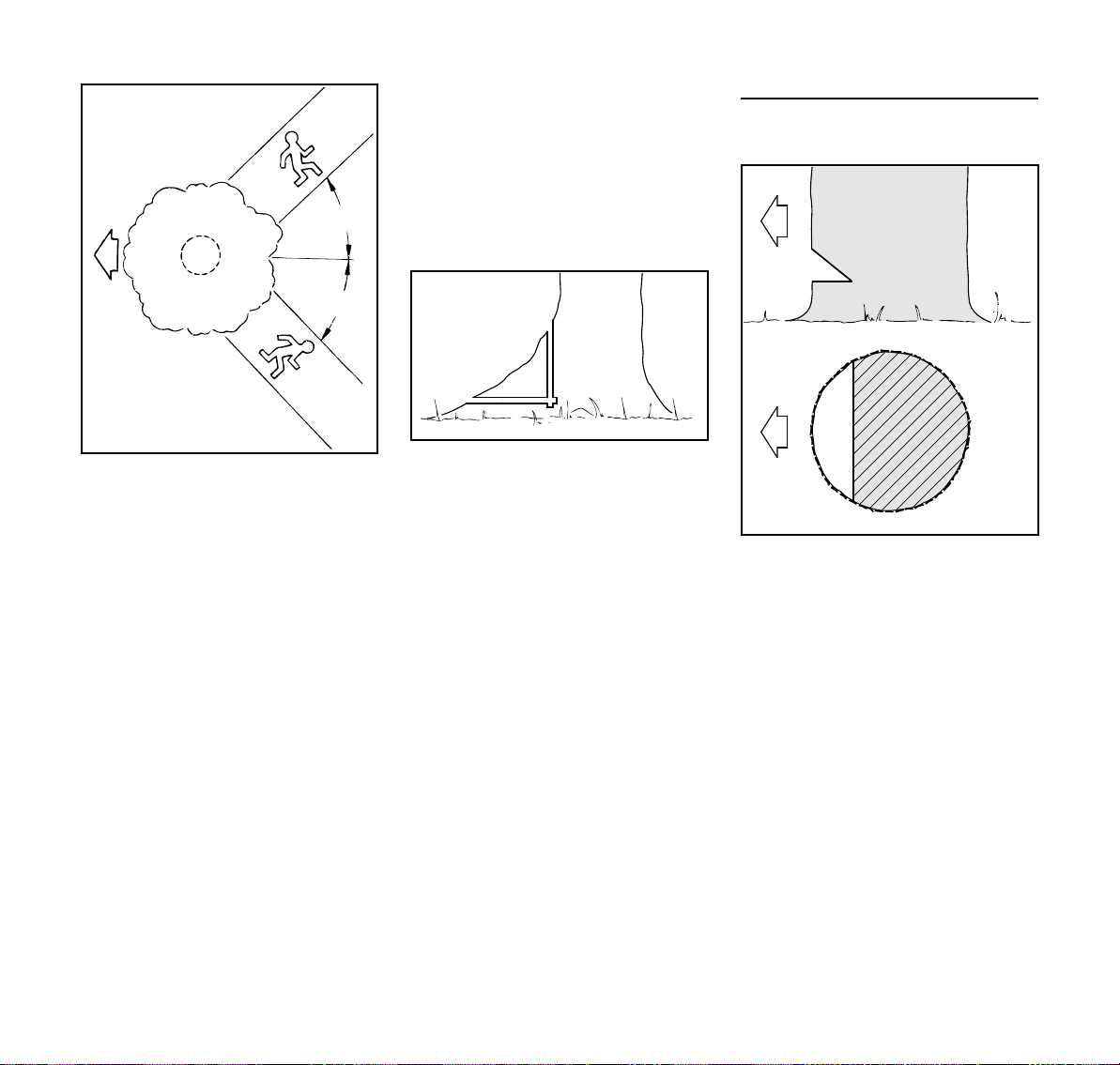
Selecting the appropriate felling cut
The selection of the appropriate felling
cut is dependent on the same tree
characteristics that must be noted when
determining the direction of fall and the
escape paths.
There are various different features of
these characteristics. This User Manual
will only describe the two most
commonly occurring variants:
left: Normal tree – vertically
upright tree with uniform
crown
right: Leaner tree - crown pointing in
direction of fall
14
MS 231, MS 231 C, MS 251, MS 251 C

English
001BA261 KN
1.
2.
3.
001BA273 KN
4.
001BA263 KN
1.
2.
3.
5.
Felling cut with stabilizing strap (normal
tree)
A) Thin trunks
Implement this felling cut when the trunk
diameter is smaller than the cutting
length of the chainsaw.
Shout a warning before starting the
felling cut.
N Plunge cut the felling cut (E) –
plunge the guide bar fully in
N Engage the spiked bumper behind
the hinge and use this as the
rotation point – reposition the
chainsaw as little as possible
N Make the felling cut up to the
hinge (1)
– Do not cut into the hinge
N Make the felling cut up to the
stabilizing strap (2)
– Do not cut into the stabilizing strap
N Set the felling wedge (3)
Shout a second warning immediately
before the tree falls.
N Cut through the stabilizing strap,
horizontal level with the felling cut,
with arms fully extended
B) Thick trunks
Implement this felling cut when the trunk
diameter is greater than the cutting
length of the machine.
Shout a warning before starting the
felling cut.
N Engage the spiked bumper at the
height of the felling cut and use this
as the rotation point – reposition the
chainsaw as little as possible
N Tip of the guide bar must penetrate
the wood before the hinge (1) –
guide the chainsaw absolutely
horizontally and swivel as widely as
possible
N Make the felling cut up to the
hinge (2)
– Do not cut into the hinge
N Make the felling cut up to the
stabilizing strap (3)
– Do not cut into the stabilizing strap
The felling cut must be continued on the
opposite side of the trunk.
Ensure that the second cut is at the
same level as the first cut.
MS 231, MS 231 C, MS 251, MS 251 C
15

English
6.
001BA274 KN
1.
2.
001BA265 KN
001BA266 KN
N Plunge cut the felling cut
N Make the felling cut up to the
hinge (4)
– Do not cut into the hinge
N Make the felling cut up to the
stabilizing strap (5)
– Do not cut into the stabilizing strap
N Set the felling wedge (6)
Shout a second warning immediately
before the tree falls.
N Cut through the stabilizing strap,
horizontal level with the felling cut,
with arms fully extended
Felling Cut with Holding Strap (Leaner)
A) Thin trunks
Implement this felling cut when the trunk
diameter is smaller than the cutting
length of the chainsaw.
16
N Plunge cut the guide bar into the
trunk until it exits on the other side
N Make the felling cut (E) towards the
hinge (1)
– Cut horizontally
– Do not cut into the hinge
N Make the felling cut towards the
holding strap (2)
– Cut horizontally
– Do not cut into the holding strap.
Shout a second warning immediately
before the tree falls.
N With outstretched arms, cut through
the holding strap at a downward
angle from outside.
MS 231, MS 231 C, MS 251, MS 251 C

English
001BA267 KN
1.
2.
3.
4.
5.
6.
001BA268 KN
B) Thick trunks
Perform this felling cut when the tree
diameter is greater than the cutting
length of the chainsaw.
N Engage the spiked bumper behind
the holding strap and use it as a
pivot – avoid repositioning the
chainsaw more than necessary.
N The guide bar nose enters the
wood (1) before it reaches the hinge
– hold the chainsaw horizontally and
swing it as far as possible.
– Do not cut into the holding strap or
hinge.
N Make the felling cut up to the
hinge (2)
– Do not cut into the hinge
N Make the felling cut up to the
holding strap (3)
– Do not cut into the holding strap.
MS 231, MS 231 C, MS 251, MS 251 C
The felling cut must be continued on the
opposite side of the trunk.
Ensure that the second cut is at the
same level as the first cut.
N Engage the spiked bumper behind
the hinge and use this as the
rotation point – reposition the
chainsaw as little as possible
N Tip of the guide bar must penetrate
the wood before the holding strap
(4) – guide the chainsaw absolutely
horizontally and swivel as widely as
possible
N Make the felling cut up to the
hinge (5)
– Do not cut into the hinge
N Make the felling cut up to the
holding strap (6)
– Do not cut into the holding strap.
Shout a second warning immediately
before the tree falls.
N With outstretched arms, cut through
the holding strap at a downward
angle from outside.
17

English
001BA248 KN
1
2
3
a
001BA244 KN
533BA001 KN
1
2
001BA185 KN
Cutting Attachment
A cutting attachment consists of the saw
chain, guide bar and chain sprocket.
The cutting attachment that comes
standard is designed to exactly match
the chain saw.
– The pitch (t) of the saw chain (1),
chain sprocket and the nose
sprocket of the Rollomatic guide bar
must match.
– The drive link gauge (2) of the saw
chain (1) must match the groove
width of the guide bar (3).
If non-matching components are used,
the cutting attachment may be damaged
beyond repair after a short period of
operation.
Chain Scabbard
Your saw comes standard with a chain
scabbard that matches the cutting
attachment.
If guide bars of different lengths are
mounted to the saw, always use a chain
scabbard of the correct length which
covers the complete guide bar.
The length of the matching guide bars is
marked on the side of the chain
scabbard.
Mounting the Bar and Chain
(side chain tensioner)
Removing the chain sprocket cover
N Unscrew the nut and remove the
chain sprocket cover.
N Turn the screw (1)
counterclockwise until the tensioner
slide (2) butts against the left end of
the housing slot.
18
MS 231, MS 231 C, MS 251, MS 251 C

English
001BA186 KN
143BA003 KN
3
1
1
2
4
001BA187 KN
1
2
3
2310BA013 KN
1
2310BA014 KN
Disengage the chain brake.
N Pull the hand guard towards the
front handle until there is an audible
click – the chain brake is
disengaged.
Fitting the chain
N Fit the guide bar over the studs (1) –
the cutting edges on the top of the
bar must point to the right.
N Engage the peg of the tensioner
slide in the locating hole (2) –- place
the chain over the sprocket (3) at
the same time.
N Turn the tensioning screw (4)
clockwise until there is very little
chain sag on the underside of the
bar – and the drive link tangs are
engaged in the bar groove.
N Refit the sprocket cover and screw
on the nut only fingertight.
N Go to chapter on "Tensioning the
Saw Chain"
Mounting the Bar and Chain
(quick chain tensioner)
Removing the chain sprocket cover
N Swing grip (1) into position (until it
engages)
N Turn the wing nut (2) to the left until
it hangs loosely in the chain
sprocket cover (3)
N Remove chain sprocket cover (3)
Mounting the tensioning gear
WARNING
Wear work gloves to protect your hands
from the sharp cutters.
N Fit the chain – start at the bar nose.
MS 231, MS 231 C, MS 251, MS 251 C
N Remove and reverse tensioning
gear (1)
19

English
2310BA015 KN
2
1
3
2310BA016 KN
2
2310BA017 KN
001BA186 KN
1
181BA012 KN
2
3
181BA013 KN
N Remove screw (2)
N Position tensioning gear (1) and
guide bar (3) relative to one another
Releasing the chain brake
N Pull hand guard towards the front
handle until it engages audibly –
chain brake is released
Fitting the saw chain
N Fit the saw chain – starting at the
nose of the guide bar – pay attention
to the position of the tensioning gear
and the cutting edges
N Turn tensioning gear (1) to the right
as far as possible
N Turn the guide bar so that the
tensioning gear faces the user
N Place the saw chain on the chain
sprocket (2)
N Slide the guide bar over the collar
screw (3); the head of the rear collar
screw must protrude into the oblong
hole
N Insert and tighten screw (2)
20
WARNING
Put on protective gloves – risk of injury
by the sharp cutters.
MS 231, MS 231 C, MS 251, MS 251 C

English
135BA011 KN
4
5
2310BA018 KN
1
142BA063 KN
N Guide the drive link into the bar
groove (see arrow) and turn the
tensioning gear to the left as far as
possible
N Fit chain sprocket cover, sliding the
guide lugs into the engine housing
openings
N turn the adjusting wheel (4) a little
until the chain sprocket cover can
be slid completely against the
engine housing
N Swing grip (5) into position (until it
engages)
N Fit wing nut and tighten lightly
N Next step: see "Tensioning the Saw
Chain"
Tensioning the Saw Chain
(side chain tensioner)
Retensioning during cutting work:
N Switch off the engine.
N Loosen the nut.
N Hold the bar nose up.
N Use a screwdriver to turn the
tensioning screw (1) clockwise until
the chain fits snugly against the
underside of the bar.
N While still holding the bar nose up,
tighten down the nut firmly.
N Go to "Checking Chain Tension".
A new chain has to be retensioned more
often than one that has been in use for
some time.
N Check chain tension frequently –
see chapter on "Operating
Instructions".
When fitting the chain sprocket cover,
the teeth of the adjusting wheel and the
tensioning gear must mesh; if
necessary,
MS 231, MS 231 C, MS 251, MS 251 C
21

English
1
2
001BA112 KN
142BA064 KN
Tensioning the Saw Chain
(quick chain tensioner)
Retensioning during cutting work:
N Shut off the engine.
N Pull out the hinged clip and loosen
the wingnut.
N Turn the adjusting wheel (1)
clockwise as far as stop.
N Tighten down the wingnut (2) firmly
by hand.
N Fold down the hinged clip.
N Go to "Checking Chain Tension"
A new chain has to be retensioned more
often than one that has been in use for
some time.
N Check chain tension frequently –
see chapter on "Operating
Instructions".
Checking Chain Tension
N Shut off the engine.
N Wear work gloves to protect your
hands.
N The chain must fit snugly against
the underside of the bar and it must
still be possible to pull the chain
along the bar by hand when the
chain brake is released.
N If necessary, retension the chain.
A new chain has to be retensioned more
often than one that has been in use for
some time.
N Check chain tension frequently –
see chapter on "Operating
Instructions".
Fuel
This engine is certified to operate on
unleaded gasoline and with the mix ratio
50:1.
Your engine requires a mixture of highquality premium gasoline and highquality two-stroke air-cooled engine oil.
Use premium branded unleaded
gasoline with a minimum octane rating
of 89 (R+M)/2.
Note: Models equipped with a catalytic
converter require unleaded gasoline. A
few tankfuls of leaded gasoline can
reduce the efficiency of the catalytic
converter by more than 50%.
Fuel with a lower octane rating may
result in preignition (causing "pinging")
which is accompanied by an increase in
engine temperature. This, in turn,
increases the risk of the piston seizure
and damage to the engine.
The chemical composition of the fuel is
also important. Some fuel additives not
only detrimentally affect elastomers
(carburetor diaphragms, oil seals, fuel
lines etc.), but magnesium castings as
well. This could cause running problems
or even damage the engine. For this
reason it is essential that you use only
high-quality fuels!
Fuels with different percentages of
ethanol are being offered. Ethanol can
affect the running behaviour of the
engine and increase the risk of lean
seizure.
22
MS 231, MS 231 C, MS 251, MS 251 C

English
001BA229 KN
001BA236 KN
Gasoline with an ethanol content of
more than 10% can cause running
problems and major damage in engines
with a manually adjustable carburetor
and should not be used in such engines.
Engines equipped with M-Tronic can be
run on gasoline with an ethanol content
of up to 25% (E25).
Use only STIHL two-stroke engine oil or
equivalent high-quality two-stroke aircooled engine oils for mixing.
We recommend STIHL 50:1 two-stroke
engine oil since it is specially formulated
for use in STIHL engines.
To ensure the maximum performance of
your STIHL engine, use a high quality 2cycle engine oil. To help your engine run
cleaner and reduce harmful carbon
deposits, STIHL recommends using
STIHL HP Ultra 2-cycle engine oil or ask
your dealer for an equivalent fully
synthetic 2-cycle engine oil.
To meet the requirements of EPA and
CARB we recommend to use STIHL HP
Ultra oil.
Do not use BIA or TCW (two-stroke
water cooled) mix oils!
Use only STIHL 50:1 heavy-duty engine
oil or an equivalent quality two-stroke
engine oil for the fuel mix in models
equipped with a catalytic converter.
Take care when handling gasoline.
Avoid direct contact with the skin and
avoid inhaling fuel vapour.
The canister should be kept tightly
closed in order to avoid any moisture
getting into the mixture.
The fuel tank and the canister in which
fuel mix is stored should be cleaned
from time to time.
Fuel mix ratio
Only mix sufficient fuel for a few days
work, not to exceed 30 days of storage.
Store in approved safety fuel-canisters
only. When mixing, pour oil into the
canister first, and then add gasoline.
Examples
Gasoline Oil (STIHL 50:1 or equiva-
lent high-quality oils)
liters liters (ml)
1 0.02 (20)
5 0.10 (100)
10 0.20 (200)
15 0.30 (300)
20 0.40 (400)
25 0.50 (500)
Dispose of empty mixing-oil canisters
only at authorized disposal locations.
Fueling
Preparing the machine
N Before fueling, clean the cap and
the area around it to ensure that no
dirt falls into the fuel tank
N Always position the machine so that
the cap is facing upwards
Opening
N Raise grip to vertical position.
MS 231, MS 231 C, MS 251, MS 251 C
23

English
001BA232 KN
001BA234 KN
001BA237 KN
001BA234 KN
001BA233 KN
001BA231 KN
001BA235 KN
001BA241 KN
Closing
N Turn the cap counterclockwise
(about a quarter turn).
Marks on tank cap and fuel tank must
line up.
N Remove the tank cap.
Filling Up with Fuel
Grip must be vertical:
N Fit the cap – marks on tank cap and
fuel tank must line up.
N Press the cap down as far as stop.
N While holding the cap depressed,
turn it clockwise until it engages in
position.
N Fold the grip down.
Tank cap is locked.
If the tank cap cannot be locked in the
fuel tank opening
Bottom of cap is twisted in relation to
top.
N Remove the cap from the fuel tank
and check it from above.
Take care not to spill fuel while fueling
and do not overfill the tank.
STIHL recommends you use the STIHL
filler nozzle for fuel (special accessory).
N Fill the fuel tank.
24
The marks on the tank cap and fuel tank
are then in alignment.
MS 231, MS 231 C, MS 251, MS 251 C

Left: Bottom of cap is twisted –
1
001BA238 KN
001BA239 KN
001BA158 KN
inner mark (1) in line with
outer mark.
Right: Bottom of cap in correct posi-
tion – inner mark is under the
grip. It is not in line with the
outer mark.
N Place the cap on the opening and
rotate it counterclockwise until it
engages the filler neck.
N Continue rotating the cap
counterclockwise (about a quarter
turn) – this causes the bottom of the
cap to be turned to the correct
position.
N Turn the cap clockwise and lock it in
position – see section on "Closing".
Chain Lubricant Filling Chain Oil Tank
For automatic and reliable lubrication of
the chain and guide bar – use only an
environmentally compatible quality
chain and bar lubricant. Rapidly
biodegradable STIHL BioPlus is
recommended.
NOTICE
Biological chain oil must be resistant to
aging (e.g. STIHL BioPlus), since it will
otherwise quickly turn to resin. This
results in hard deposits that are difficult
to remove, especially in the area of the
chain drive and chain. It may even cause
the oil pump to seize.
The service life of the chain and guide
bar depends on the quality of the
lubricant. It is therefore essential to use
only a specially formulated chain
lubricant.
WARNING
Do not use waste oil. Renewed contact
with waste oil can cause skin cancer.
Moreover, waste oil is environmentally
harmful.
NOTICE
Waste oil does not have the necessary
lubricating properties and is unsuitable
for chain lubrication.
Preparations
N Thoroughly clean the oil filler cap
and the area around it to ensure that
no dirt falls into the tank.
N Position the machine so that the
filler cap is facing up.
N Open the filler cap.
Fill up with chain oil.
N Refill the chain oil tank every time
you refuel.
Take care not to spill chain oil while
refilling and do not overfill the tank.
STIHL recommends you use the STIHL
filler nozzle for chain oil (special
accessory).
N Close the filler cap.
There must still be a small amount of oil
in the oil tank when the fuel tank is
empty.
English
MS 231, MS 231 C, MS 251, MS 251 C
25

English
143BA024 KN
143BA011 KN
If the oil level in the tank does not go
down, the reason may be a fault in the oil
supply system: Check chain lubrication,
clean the oilways, contact your dealer
for assistance if necessary STIHL
recommends that you have servicing
and repair work carried out exclusively
by an authorized STIHL servicing
dealer.
Checking Chain Lubrication
The saw chain must always throw off a
small amount of oil.
NOTICE
Never operate your saw without chain
lubrication. If the chain runs dry, the
whole cutting attachment will be
irretrievably damaged within a very short
time. Always check chain lubrication and
the oil level in the tank before starting
work.
Every new chain has to be broken in for
about 2 to 3 minutes.
After breaking in the chain, check chain
tension and adjust if necessary – see
"Checking Chain Tension".
Chain Brake
Locking the chain
– in an emergency
– when starting
– at idling speed
The chain brake is activated by pushing
the hand guard toward the bar nose with
your left hand – or by inertia in certain
kickback situations: The chain is
stopped and locked.
26
MS 231, MS 231 C, MS 251, MS 251 C

English
143BA012 KN
2310BA000 KN
2310BA001 KN
Releasing the chain brake
N Pull the hand guard back toward the
front handle,
NOTICE
Always disengage chain brake before
accelerating the engine (except when
checking its operation) and before
starting cutting work.
High revs with the chain brake engaged
(chain locked) will quickly damage the
powerhead and chain drive (clutch,
chain brake).
The chain brake is also activated by the
inertia of the front hand guard if the
kickback force of the saw is high
enough: The hand guard is accelerated
toward the bar nose – even if your left
hand is not behind the hand guard, e.g.
during felling cut.
The chain brake will operate only if the
hand guard has not been modified in any
way.
Check operation of the chain brake
Before starting work: Run engine at idle
speed, engage the chain brake (push
hand guard toward bar nose) and open
the throttle wide for no more than
3 seconds – the chain must not rotate.
The hand guard must be free from dirt
and move freely.
Chain brake maintenance
The chain brake is subject to normal
wear. It is necessary to have it serviced
and maintained regularly by trained
personnel. STIHL recommends that you
have servicing and repair work carried
out exclusively by an authorized STIHL
servicing dealer. Maintain the following
servicing intervals:
Full-time usage: every 3
months
Part-time usage: every 6
months
Occasional usage: every 12
months
Winter Operation
Pre-heating carburetor
N Remove the shroud – see "Shroud"
At temperatures below +10 °C
N Using a screwdriver, pry the shutter
out of the s (summer operation)
position
N Place the shutter with the opening in
the direction of the chain saw in
the r position (winter operation) –
shutter must audibly snap into place
N Fit the shroud – see "Shroud"
MS 231, MS 231 C, MS 251, MS 251 C
27

English
STOP
0
001BA140 KN
Heated air is now drawn in from around
the cylinder and circulates around the
carburetor – this helps prevent
carburetor icing.
At temperatures above +20 °C
N Ensure that the shutter is always
returned to position s (summer
operation), otherwise the engine
may malfunction due to overheating
At temperatures below -10 °C
N if the chain saw is extremely cold
(frost formation) – after starting,
bring the engine up to operating
temperature at increased idle speed
(disengage chain brake!)
In case of erratic idling behavior or poor
acceleration
N Turn the low speed screw (L)
1/4 turn counterclockwise
Whenever the low speed screw (L) has
been adjusted, it is usually also
necessary to adjust the idle speed
adjusting screw (LA), see "Setting the
carburetor".
Air filter system
N Retrofit new air filter if necessary –
see "Air filter system"
Starting / Stopping the
Engine
Versions with Easy2Start
WARNING
This machine is extremely simple and
easy to start, even for children.
To reduce the risk of serious or fatal
injury:
– do not allow children or other
unauthorized persons to attempt to
start or otherwise use the machine
– never allow children or
unauthorized persons access to the
machine
– never leave the machine
unattended while working or during
work breaks
– after work, store in a safe, secure
location out of the reach of children
and other unauthorized persons
Positions of Master Control lever
Stop 0 – engine off – the ignition is
switched off
Normal run position (F) – engine runs or
can fire.
Starting throttle (n) – this position is
used to start a warm engine. The Master
Control lever moves to the normal run
position as soon as the throttle trigger is
squeezed.
Choke shutter closed (l) – this position
is used to start a cold engine.
Setting the Master Control Lever
28
To move the Master Control lever from
the normal run position (F) to choke
closed (l), press down the throttle
trigger lockout and squeeze the throttle
MS 231, MS 231 C, MS 251, MS 251 C

English
2310BA008 KN
trigger at the same time and hold them in
that position – now set the Master
Control lever.
To select the starting throttle
position (n), move the Master Control
lever to choke closed (l) first, then
push it into the starting throttle
position (n).
The Master Control lever must be in the
choke closed position (l) for the
changeover to the starting throttle
position (n).
The Master Control lever moves from
the starting throttle position (n) to the
run position (F) when you press down
the throttle trigger lockout and blip the
throttle trigger at the same time.
To switch off the engine, move the
Master Control lever to Stop (0).
Choke shutter closed (l)
– if the engine is cold
– If the engine stalls when you open
the throttle after starting.
– If the fuel tank was run until empty
(engine stopped).
Starting throttle position (n)
– If the engine is warm, i.e. if it has
been running for about one minute.
– when the engine begins to fire.
– after clearing a flooded combustion
chamber.
Fuel Pump
Press the fuel pump bulb several times –
even if the bulb is already filled with fuel:
– When starting for the first time.
– If the fuel tank was run until empty
(engine stopped).
Holding the Saw
There are two ways of holding the saw
when starting.
On the ground
N Place your saw on the ground.
Make sure you have a firm footing –
check that the chain is not touching
any object or the ground.
N Hold the saw firmly on the ground
with your left hand on the front
handle – your thumb should be
under the handle.
N Put your right foot into the rear
handle and press down.
MS 231, MS 231 C, MS 251, MS 251 C
29

English
2310BA009 KN
231BA010 KN
Between knees or thighs
N Hold the rear handle tightly between
your legs, just above the knees.
N Hold the front handle firmly with
your left hand – your thumb should
be under the handle.
Cranking
Standard versions
N Pull the starter grip slowly with your
right hand until you feel it engage –
and then give it a brisk strong pull
and push down the front handle at
the same time. Do not pull out the
starter rope to full length – it might
otherwise break. Do not let the
starter grip snap back. Guide it
slowly back into the housing so that
the starter rope can rewind properly.
Machines without additional manual fuel
pump: If the engine is new or after a long
out-of-service period, it may be
necessary to pull the starter rope several
times to prime the fuel system.
Versions with Easy2Start
The Easy2Start stores the energy
required to start the saw. For this reason
there may be a delay of a few seconds
between cranking the engine and it
actually starting.
There are two ways of starting machines
with Easy2Start:
N Hold the starter grip with your right
hand and pull it out slowly and
steadily – or – hold the starter grip
with your right hand and give it
several short pulls, using only a
short length of rope for each pull.
N Push down the handle while
cranking. Do not pull out the rope to
its full length – it might otherwise
break.
N Do not let the starter grip snap back.
Guide it slowly back into the housing
so that the starter rope can rewind
properly.
Starting the saw
WARNING
Bystanders must be well clear of the
general work area of the saw.
N Observe safety precautions.
30
MS 231, MS 231 C, MS 251, MS 251 C

English
2310BA021 KN
3
1
2
4
2310BA002 KN
0
4
2310BA003 KN
STOP
0
3
4
2310BA004 KN
STOP
0
001BA186 KN
Versions with manual fuel pump
N Press the fuel pump bulb at least
five times – even if the bulb is
already filled with fuel.
All models
Choke shutter closed (l)
– If the engine is cold (also use this
position if the engine stopped when
you opened the throttle after
starting)
Starting throttle position (n)
– If the engine is warm, i.e. if it has
been running for about one minute.
N Hold and start your saw as
described.
When Engine Begins to Fire
N Set the Master Control lever (4) to
the starting throttle position (n).
N Hold and start your saw as
described.
As Soon as Engine Runs
N Press down the trigger lockout and
blip the throttle trigger (3) – the
Master Control lever (4) moves to
the run position (F) and the engine
settles down to idling speed.
NOTICE
As the chain brake is still engaged, the
engine must be returned to idling speed
immediately – or the engine housing and
chain brake might otherwise be
damaged.
N Push the hand guard (1) forward –
the chain is locked.
N Press down the trigger lockout (2)
and pull the throttle trigger (3) at the
same time. Set Master Control
lever (4) to:
MS 231, MS 231 C, MS 251, MS 251 C
N Pull the hand guard back toward the
front handle.
The chain brake is now disengaged –
your saw is ready for operation.
31

English
NOTICE
Always disengage chain brake before
accelerating the engine. High revs with
the chain brake engaged (chain locked)
will quickly damage the clutch and chain
brake.
At very low outside temperatures
N Allow engine to warm up at part
throttle.
N Change over to winter operation if
necessary – see “Winter Operation”.
Shutting Off the Engine
N Move the Master Control lever to the
stop position (0).
If Engine Does Not Start
If you did not move the Master Control
lever from the choke closed
position (l) to the starting throttle
position (n) quickly enough after the
engine began to fire, the combustion
chamber may be flooded.
N Move the Master Control lever to the
stop position (0).
N Remove the spark plug – see
"Spark Plug".
N Dry the spark plug.
N Crank the engine several times with
the starter to clear the combustion
chamber.
N Refit the spark plug – see "Spark
Plug".
N Set Master Control lever to the
starting throttle position (n) – even
if the engine is cold.
N Now start the engine.
Operating Instructions
During the break-in period
A factory new machine should not be run
at high revs (full throttle off load) for the
first three tank fillings. This avoids
unnecessarily high loads during the
break-in period. As all moving parts
have to bed in during the break-in
period, the frictional resistances in the
shortblock are greater during this period.
The engine develops its maximum
power after about 5 to 15 tank fillings.
During work
NOTICE
Do not make the mixture leaner to
achieve an apparent increase in power –
this could damage the engine – see
"Adjusting the Carburetor".
NOTICE
Open the throttle only when the chain
brake is off. Running the engine at high
revs with the chain brake engaged
(chain locked) will quickly damage the
shortblock and chain drive (clutch, chain
brake).
Check chain tension frequently
A new saw chain must be retensioned
more frequently than one that has been
in use already for an extended period.
32
MS 231, MS 231 C, MS 251, MS 251 C

English
2
3
1
143BA026 KN
Chain cold
Tension is correct when the chain fits
snugly against the underside of the bar
but can still be pulled along the bar by
hand. Retension if necessary – see
"Tensioning the Saw Chain".
Chain at operating temperature
The chain stretches and begins to sag.
The drive links must not come out of the
bar groove on the underside of the bar –
the chain may otherwise jump off the
bar. Retension the chain – see
"Tensioning the Saw Chain".
NOTICE
The chain contracts as it cools down. If it
is not slackened off, it can damage the
crankshaft and bearings.
After a long period of full-throttle
operation
After a long period of full-throttle
operation, allow engine to run for a while
at idle speed so that the heat in the
engine can be dissipated by flow of
cooling air. This protects enginemounted components (ignition,
carburetor) from thermal overload.
After finishing work
N Slacken off the chain if you have
retensioned it at operating
temperature during work.
NOTICE
Always slacken off the chain again after
finishing work. The chain contracts as it
cools down. If it is not slackened off, it
can damage the crankshaft and
bearings.
Short-term storage
Wait for engine to cool down. Keep the
machine with a full tank of fuel in a dry
place, well away from sources of
ignition, until you need it again.
Long-term storage
See "Storing the machine"
Taking Care of the Guide Bar
N Flip the bar – after each sharpening
and each time the chain is changed
– to avoid uneven wear, especially
at the sprocket nose and on the
bottom
N Periodically clean the oil inlet
hole (1), oil outlet channel (2) and
bar groove (3)
N Measure groove depth – using the
measuring tool on the file gauge
(special accessory) – in the area
with the greatest wear
Chain type Chain pitch Minimum
groove depth
Picco 1/4“ P 4.0 mm
Rapid 1/4“ 4.0 mm
MS 231, MS 231 C, MS 251, MS 251 C
33

English
1
1
1
2710BA003 KN
2
5902BA009 KN
5902BA008 KN
Picco 3/8“ P 5.0 mm
Rapid 3/8“; 0.325“ 6.0 mm
Rapid 0.404“ 7.0 mm
If the groove is not at least this deep:
N Replace guide bar
Otherwise the drive links will grind
against the base of the groove – the
bottoms of the cutters and the tie straps
will not lie against the bar.
Shroud
Remove shroud
N Move the Master Control Lever to
the stop position 0
N Push the front hand guard forwards
– the saw chain is blocked
N Loosen screws (1)
N Remove the shroud (2)
Refitting the shroud
N Refit the shroud and tighten the
screws
Air Filter System
The air filter system can be adapted to
suit different operating conditions by
installing different filters. Changing the
filter is quick and simple.
Fleece filter
N Fleece filter for normal operating
conditions and dry work areas.
HD2 filter
N HD2 filter (black filter frame, pleated
filter material) for extreme wintry
conditions (e.g. powder or drifting
snow) or very dusty work areas.
34
MS 231, MS 231 C, MS 251, MS 251 C

English
1.
2710BA000 KN
2.
2710BA001 KN
2.
1.
Cleaning the Air Filter
If there is a noticeable loss of engine
power.
N Remove the shroud – see "Shroud".
Removing the air filter
N Clean away loose dirt from around
the filter.
NOTICE
To avoid damaging the filter, do not use
tools for removing and installing the air
filter.
N Rotate the air filter a 1/4 turn
counterclockwise and lift it away in
the direction of the rear handle.
N Always replace a damaged filter.
Cleaning the air filter (fleece filter)
N Knock out the filter or blow it clear
with compressed air from the inside
outwards.
If knocking it out or blowing it clear is not
sufficient to remove stubborn dirt, or if
the filter fabric is sticky, perform the
following steps:
N Wash the filter in STIHL special
cleaner (special accessory) or a
clean, non-flammable solution (e.g.
warm soapy water). Rinse the filter
from the inside outwards under a jet
of water – do not use a pressure
washer.
N Dry the filter components – do not
expose to high temperatures.
NOTICE
High temperatures and oil can damage
the air filter. Filter efficiency can
deteriorate as a result.
– Allow air filter to dry without using
any external source of heat.
– Do not impregnate the filter with oil.
N Install the air filter.
Cleaning the air filter (HD2 filter)
N Knock out the filter.
N Spray outside of filter with STIHL
special cleaner or soapy water.
N Rinse outside of filter under warm
running water.
NOTICE
High temperatures and oil can damage
the air filter. Filter efficiency can
deteriorate as a result.
– Allow air filter to dry without using
any external source of heat.
– Do not impregnate the filter with oil.
N Allow air filter to dry.
N Install the air filter.
Installing the air filter
N Place the air filter in position.
N Push the air filter in the direction of
the filter housing and turn it
clockwise at the same time until it
engages – the "STIHL" name must
be horizontal.
N Install the shroud – see "Shroud".
MS 231, MS 231 C, MS 251, MS 251 C
35

English
2310BA027 KN
2310BA028 KN
Engine Management Adjusting the Carburetor
Exhaust emissions are controlled by the
design of the engine and components
(e.g. carburation, ignition, timing and
valve or port timing).
Basic information
The carburetor comes from the factory
with a standard setting.
The carburetor has been adjusted for
optimum performance and fuel
efficiency in all operating states.
Standard setting
N Switch off the engine
N Check the air filter – clean or replace
it if necessary
N Turn the high speed adjusting
screw (H) counterclockwise as far
as possible (max. 3/4 turn)
N Turn the low speed adjusting
screw (L) clockwise until it is firmly
in its seat – then back off 1/4 turn
Setting the idle speed
N Make standard setting
N Start engine and let it warm up
Engine stops when idling
N Turn the idle speed adjusting screw
(LA) clockwise until the saw chain
begins to run – then turn it back
23/4turn.
Saw chain rotates at idle speed
N Turn the idle speed screw (LA)
counterclockwise until the saw
chain stops turning – then turn
another 2 3/4 turns in the same
direction
WARNING
If the saw chain continues to keep
rotating in idle even after adjustment,
have the chain saw checked by a
servicing dealer.
Speed erratic when idling; poor
acceleration (despite standard setting of
low speed adjusting screw)
The idle setting is too lean.
N Carefully turn the low speed
adjusting screw (L)
counterclockwise until the engine
runs smoothly and accelerates
properly.
36
MS 231, MS 231 C, MS 251, MS 251 C

English
2310BA023 KN
2
1
2310BA006 KN
Whenever the low speed adjusting
screw (L) has been adjusted, it is usually
also necessary to readjust the idle
speed adjusting screw (LA).
Correcting the carburetor setting for use
at high altitudes
The setting may have to be marginally
corrected if engine performance is
unsatisfactory at high altitudes:
N Make standard setting
N Let the engine warm up
N Turn the high speed adjusting
screw (H) slightly clockwise (leaner)
– max. up to the stop
NOTICE
After descending from a high altitude,
restore the carburetor setting to the
standard setting.
If you make the setting too lean it will
increase the risk of engine damage
through lack of lubrication and
overheating.
Spark Arresting Screen in
Muffler
N If engine performance deteriorates,
check the spark arresting screen in
the muffler
N Let the muffler cool down
N Unscrew the screw (1)
N Pull out spark arresting screen (2)
N Clean the dirty spark arresting
screen, replace if damaged or
heavily carbonized
N Refit the spark arresting screen
N Fit screw
Spark Plug
N If the engine is down on power,
difficult to start or runs poorly at idle
speed, first check the spark plug.
N Fit a new spark plug after about 100
operating hours – or sooner if the
electrodes are badly eroded. Install
only suppressed spark plugs of the
type approved by STIHL – see
"Specifications".
Removing the spark plug
N Remove the shroud – see "Shroud"
N Pull off the spark plug boot
N Unscrew spark plug
MS 231, MS 231 C, MS 251, MS 251 C
37

English
000BA039 KN
A
1
000BA045 KN
2310BA012 KN
Checking the Spark Plug
N Clean dirty spark plug.
N Check electrode gap (A) and
readjust if necessary – see
"Specifications".
N Rectify the problems which have
caused fouling of the spark plug.
Possible causes are:
– Too much oil in fuel mix.
– Dirty air filter.
– Unfavorable running conditions.
N Use resistor type spark plugs with a
properly tightened adapter nut.
Installing the spark plug
N Fit spark plug by hand
N Tighten the spark plug and press on
the spark plug boot firmly
N Fit the shroud – see "Shroud"
Storing the Machine
For periods of 3 months or longer
N Drain and clean the fuel tank in a
well ventilated area.
N Dispose of fuel properly in
accordance with local
environmental requirements.
N Run the engine until the carburetor
is dry – this helps prevent the
carburetor diaphragms sticking
together.
N Remove the saw chain and guide
bar, clean them and spray with
corrosion inhibiting oil.
N Thoroughly clean the machine – pay
special attention to the cylinder fins
and air filter.
N If you use a biological chain and bar
lubricant, e.g. STIHL BioPlus,
completely fill the chain oil tank.
N Store the machine in a dry, high or
locked location, out of the reach of
children and other unauthorized
persons.
WARNING
Arcing may occur if the adapter nut (1) is
loose or missing. Working in an easily
combustible or explosive atmosphere
may cause a fire or an explosion. This
can result result in serious injuries or
damage to property.
38
MS 231, MS 231 C, MS 251, MS 251 C

English
001BA121 KN
001BA122 KN
1
2
4
5
6
1
2
3
6
Checking and Replacing the
Chain Sprocket
N Remove chain sprocket cover, saw
chain and guide bar.
N Release chain brake – pull hand
guard against the front handle
Fit new chain sprocket
– after use of two saw chains or
earlier
– if the wear marks (arrows) are
deeper than 0.5 mm – otherwise the
service life of the saw chain is
reduced – use check gauge (special
accessory) to test
Using two saw chains in alternation
helps preserve the chain sprocket.
STIHL recommends use of original
STIHL chain sprockets in order to
ensure optimal functioning of the chain
brake.
N After refitting, turn the clutch drum
and/or spur chain sprocket approx.
1 full turn so that the carrier for the
oil pump drive engages – with
QuickStop Super chain brake, press
throttle trigger lockout beforehand
N Refit the rim sprocket – cavities
toward the outside
N Refit washer and E-clip on the
crankshaft
N Use a screwdriver to remove the E-
clip (1)
N Remove the washer (2)
N Remove rim sprocket (3)
N Inspect transport profile on the
clutch drum (4) – if there are also
heavy signs of wear, also replace
the clutch drum
N Remove clutch drum or spur chain
sprocket (5) including needle
cage (6) from the crankshaft – with
QuickStop Super chain brake, press
throttle trigger lockout beforehand
Install spur chain sprocket / rim sprocket
N Clean crankshaft stub and needle
cage and lubricate with STIHL
lubricant (special accessory)
N Slide needle cage onto the
crankshaft stub
MS 231, MS 231 C, MS 251, MS 251 C
39

English
689BA027 KN
a
A
B
689BA021 KN
Maintaining and Sharpening
the Saw Chain
Sawing effortlessly with a properly
sharpened saw chain
A properly sharpened saw chain cuts
through wood effortlessly even with very
little pushing.
Never use a dull or damaged saw chain
– this leads to increased physical strain,
increased vibration load, unsatisfactory
cutting results and increased wear.
N Clean the saw chain
N Check the saw chain for cracks and
damaged rivets
N Replace damaged or worn chain
components and adapt these parts
to the remaining parts in terms of
shape and level of wear – rework
accordingly
Carbide-tipped (Duro) saw chains are
especially wear-resistant. For an optimal
sharpening result, STIHL recommends
STIHL servicing dealers.
WARNING
Compliance with the angles and
dimensions listed below is absolutely
necessary. An improperly sharpened
saw chain – especially depth gauges
that are too low – can lead to increased
kickback tendency of the chain saw –
risk of injury!
Chain pitch
The chain pitch marking (a) is embossed
in the area of the depth gauge of each
cutter.
Marking (a)Chain pitch
Inches mm
7 1/4 P 6.35
1 or 1/4 1/4 6.35
6, P or PM 3/8 P 9.32
2 or 325 0.325 8.25
3 or 3/8 3/8 9.32
4 or 404 0.404 10.26
The diameter of file to be used depends
on the chain pitch – see table
"Sharpening tools".
The angles of the cutter must be
maintained during resharpening.
Sharpening and side plate angles
A Sharpening angle
STIHL saw chains are sharpened with a
30° sharpening angle. Ripping chains,
which are sharpened with a 10°
sharpening angle, are exceptions.
Ripping chains have an X in the
designation.
B Side plate angle
The correct side plate angle results
automatically when the specified file
holder and file diameter are used.
Tooth shapes Angle (°)
AB
Micro = semi-chisel tooth,
e. g., 63 PM3, 26 RM3,
36 RM
Super = full chisel tooth,
e. g., 63 PS3, 26 RS,
36 RS3
Ripping chain, e. g.,
63 PMX, 36 RMX
The angles must be identical for all
cutters in the saw chain. Varying angles:
Rough, uneven running of the saw
chain, increased wear – even to the
point of saw chain breakage.
30 75
30 60
10 75
40
MS 231, MS 231 C, MS 251, MS 251 C

English
689BA025 KN
001BA203 KN
689BA018 KN
90°
689BA043 KN
689BA023 KN
a
File holder
N Use a file holder
Always use a file holder (special
accessory, see table "Sharpening tools")
when sharpening saw chains by hand.
File holders have markings for the
sharpening angle.
Use only special saw chain files! Other
files are unsuitable in terms of shape
and type of cutting.
To check the angles
Proper sharpening
N Select sharpening tools in
accordance with chain pitch
N Clamp guide bar if necessary
N Block saw chain – push the hand
guard forward
N To advance the saw chain, pull the
hand guard toward the handlebar:
The chain brake is disengaged.
With the Quickstop Super chain
brake system, additionally press the
throttle trigger lockout
N Sharpen frequently, removing little
ma ter ial – tw o or three st rok es of the
file are usually sufficient for simple
resharpening
markings on the file holder – rest the
file holder on the tooth head and the
depth gauge
N File only from the inside outward
N The file only sharpens on the
forward stroke – lift the file on the
backstroke
N Do not file tie straps and drive links
N Rotate the file a little periodically in
order to avoid uneven wear
N To remove file burr, use a piece of
hardwood
N Check angle with file gauge
All cutters must be equally long.
With varying cutter lengths, the cutter
heights also vary and cause rough
running of the saw chain and chain
breakage.
N All cutters must be filed down equal
to the length of the shortest cutter –
ideally, one should have this done
by a servicing dealer using an
electric sharpener
STIHL filing gauge (special accessory,
see table "Sharpening tools") – a
universal tool for checking sharpening
and side plate angles, depth gauge
setting, and tooth length, as well as
cleaning grooves and oil inlet holes.
MS 231, MS 231 C, MS 251, MS 251 C
N Guide the file: horizontally ( at a right
angle to the side surface of the
guide bar) in accordance with the
specified angle – according to the
Depth gauge setting
The depth gauge determines the depth
to which the cutter penetrates the wood
and thus the chip thickness.
41

English
2
689BA061 KN
1
689BA051 KN
689BA044 KN
689BA052 KN
a Required distance between depth
gauge and cutting edge
When cutting softwood outside of the
frost season, the distance can be
increased by up to 0.2 mm (0.008").
Chain pitch Depth gauge
Distance (a)
Inches (mm) mm (Inches)
1/4 P (6.35) 0.45 (0.018)
1/4 (6.35) 0.65 (0.026)
3/8 P (9.32) 0.65 (0.026)
0.325 (8.25) 0.65 (0.026)
3/8 (9.32) 0.65 (0.026)
0.404 (10.26) 0.80 (0.031)
Lowering the depth gauges
The depth gauge setting is lowered
when the cutter is sharpened.
N Check the depth gauge setting after
each sharpening
Saw chains with humped drive link (2) –
upper part of the humped drive link (2)
(with service mark) is lowered at the
same time as the depth gauge of the
cutter.
WARNING
The rest of the humped drive link must
not be filed; otherwise, this could
increase the tendency of the chain saw
to kick back.
N Rework the depth gauge so that it is
flush with the file gauge
WARNING
Depth gauges that are too low increase
the kickback tendency of the chain saw.
N Lay the file gauge on the saw chain
– the highest point of the depth
gauge must be flush with the file
gauge
N After sharpening, clean the saw
chain thoroughly, removing any
filings or grinding dust – lubricate
the saw chain thoroughly
N In the event of extended periods of
disuse, store saw chains in cleaned
and oiled condition
N Lay the appropriate file gauge (1)
for the chain pitch on the saw chain
and press it against the cutter to be
checked – if the depth gauge
protrudes past the file gauge, the
depth gauge must be reworked
42
N Afterwards, dress the leading edge
of the depth gauge parallel to the
service mark (see arrow) – when
doing this, be careful not to further
lower the highest point of the depth
gauge
MS 231, MS 231 C, MS 251, MS 251 C

English
Sharpening tools (special accessories)
Chain pitch Round file ^ Round file File holder File gauge Taper square file Sharpening set
Inches (mm) mm (Inches) Part number Part number Part number Part number Part number
1/4P (6.35) 3.2 (1/8) 5605 771 3206 5605 750 4300 0000 893 4005 0814 252 3356 5605 007 1000
1/4 (6.35) 4.0 (5/32) 5605 772 4006 5605 750 4327 1110 893 4000 0814 252 3356 5605 007 1027
3/8 P (9.32) 4.0 (5/32) 5605 772 4006 5605 750 4327 1110 893 4000 0814 252 3356 5605 007 1027
0.325 (8.25) 4.8 (3/16) 5605 772 4806 5605 750 4328 1110 893 4000 0814 252 3356 5605 007 1028
3/8 (9.32) 5.2 (13/64) 5605 772 5206 5605 750 4329 1110 893 4000 0814 252 3356 5605 007 1029
0.404 (10.26) 5.5 (7/32) 5605 772 5506 5605 750 4330 1106 893 4000 0814 252 3356 5605 007 1030
1)
consisting of file holder with round file, taper square file and file gauge
1)
MS 231, MS 231 C, MS 251, MS 251 C
43

English
Maintenance and Care
The following maintenance intervals apply for normal operating conditions only. When working under
difficult conditions (high accumulation of dust, highly resinous lumber, lumber from tropical trees, etc.)
or longer than normal each day, the specified intervals must be shortened accordingly. If you only use
the tool occasionally, extend the intervals accordingly.
Before starting work
At the end of work and/or
daily
Whenever tank is refilled
Weekly
Complete machine
Throttle trigger, throttle trigger lockout, choke
lever, stop switch, master control lever (dependent
on equipment)
Chain brake
Manual fuel pump (if present)
Fuel pick-up body / filter in fuel tank
Fuel tank Clean X
Lubricating oil tank Clean X
Chain lubrication check X
Saw chain
Guide bar
Chain sprocket check X
Air filter
Visual inspection (condition, leaks) XX
Clean X
Function test XX
Function test XX
Have checked by dealer
check X
Have repaired by a specialist dealer
check X
Clean, replace filter insert XX
replace XXX
Check, pay attention to sharpness XX
Checking the chain tension XX
sharpen X
Check (wear, damage) X
Clean and turn over X
Deburr X
replace XX
Clean XX
replace X
1)
1)
Monthly
Annually
If faulty
If damaged
As required
X
X
44
MS 231, MS 231 C, MS 251, MS 251 C

English
The following maintenance intervals apply for normal operating conditions only. When working under
difficult conditions (high accumulation of dust, highly resinous lumber, lumber from tropical trees, etc.)
or longer than normal each day, the specified intervals must be shortened accordingly. If you only use
the tool occasionally, extend the intervals accordingly.
Before starting work
At the end of work and/or
daily
Whenever tank is refilled
Weekly
Monthly
Annually
If faulty
If damaged
As required
Anti-vibration elements
Air intake on fan housing Clean XX X
Cylinder fins Clean XX
Carburetor
Spark plug
Accessible screws and nuts (except adjusting
screws)
Spark arresting screen in muffler
Chain catcher
Safety information label replace X
1)
STIHL recommends STIHL servicing dealer
2)
When using professional chainsaws (with a power output of 3.4 kW or more) for the first time, tighten the cylinder block screws after 10 to 20 hours of operation
check XX
Have replaced by servicing dealer
Check idle adjustment – saw chain must not
rotate
Set the idle speed; if required have the chainsaw
repaired by a specialist dealer
1)
X
XX
1)
X
Adjust electrode gap X
Replace after 100 hours of operation
2)
Tighten
Have checked by dealer
Have cleaned; if required have replaced by specialist dealer
1)
1)
X
X
X
check X
replace X
MS 231, MS 231 C, MS 251, MS 251 C
45

English
4
8
21
10
15
16
1
1
#
13
2310BA029 ST
17
7
14
11
12
6
9
3
1
23
24
22
19
20
18
5
7
25
26
2
Main Parts
1 Shroud Lock
2 Carburetor Adjusting Screws
3 Fuel Pump
4 Shutter (Summer and Winter
Operation)
5 Chain Brake
6 Chain Sprocket
7 Chain Sprocket Cover
8 Chain Catcher
9 Side Chain Tensioner
10 Bumper Spike
11 Guide Bar
12 Oilomatic Saw Chain
13 Adjusting Wheel1) for Quick Chain
Tensioner
14 Handle of Wingnut1) for Quick Chain
Tensioner
15 Oil Filler Cap
16 Muffler (with Spark Arresting
Screen)
17 Front Hand Guard
18 Front Handle (Handlebar)
19 Spark Plug Boot
20 Starter Grip
21 Fuel Filler Cap
22 Master Control Lever
23 Throttle Trigger
24 Throttle Trigger Lockout
25 Rear Handle
26 Rear Hand Guard
# Serial Number
1)
1)
46
1)
Depending on Model
MS 231, MS 231 C, MS 251, MS 251 C

English
Definitions
1 Shroud Lock
Lock for the shroud.
2 Carburetor Adjusting Screws
For tuning the carburetor.
3 Fuel Pump
Provides additional fuel feed for a
cold start.
4 Shutter (Summer and Winter
Operation)
With summer and winter positions.
Carburetor is heated in winter
position.
5Chain Brake
A device to stop the rotation of the
chain. Is activated in a kickback
situation by the operator's hand or
by inertia.
6 Chain Sprocket
The toothed wheel that drives the
saw chain.
7 Chain Sprocket Cover
Covers the sprocket.
8 Chain Catcher
Helps to reduce the risk of operator
contact by a chain when it breaks or
comes off the bar.
9 Side Chain Tensioner
Permits precise adjustment of chain
tension.
10 Bumper Spike
Toothed stop for holding saw steady
against wood.
11 Guide Bar
Supports and guides the saw chain.
12 Oilomatic Saw Chain
A loop consisting of cutters, tie
straps and drive links.
13 Adjusting Wheel for Quick Chain
Tensioner
Permits precise adjustment of chain
tension.
14 Handle of Wingnut for Quick Chain
Tensioner
Has to be released to tension chain
with adjusting wheel.
15 Oil Filler Cap
For closing the oil tank.
16 Muffler (with Spark Arresting
Screen)
Muffler reduces engine exhaust
noise and diverts exhaust gases
away from operator.
Spark arresting screen is designed
to reduce the risk of fire.
17 Front Hand Guard
Provides protection against
projecting branches and helps
prevent left hand from touching the
chain if it slips off the handlebar. It
also serves as the lever for chain
brake activation.
18 Front Handle (Handlebar)
Handlebar for the left hand at the
front of the saw.
19 Spark Plug Boot
Connects the spark plug with the
ignition lead.
20 Starter Grip
The grip of the pull starter, for
starting the engine.
21 Fuel Filler Cap
For closing the fuel tank.
22 Master Control Lever
Lever for starting, operating and
stop-engine positions.
23 Throttle Trigger
Controls the speed of the engine.
24 Throttle Trigger Lockout
Must be depressed before the
throttle trigger can be activated.
25 Rear Handle
The support handle for the right
hand, located at the rear of the saw.
26 Rear Hand Guard
Gives added protection to
operator's right hand.
Guide Bar Nose
The exposed end of the guide bar.
(not illustrated, see chapter
"Tensioning the Saw Chain")
Clutch
Couples engine to chain sprocket
when engine is accelerated beyond
idle speed. (not illustrated)
Anti-Vibration System
The anti-vibration system includes a
number of anti-vibration elements
designed to reduce the
transmission of vibrations created
by the engine and cutting
attachment to the operator's hands.
(not illustrated)
MS 231, MS 231 C, MS 251, MS 251 C
47

English
Specifications
EPA / CEPA
The Emission Compliance Period
referred to on the Emissions
Compliance Label indicates the number
of operating hours for which the engine
has been shown to meet Federal
emission requirements.
Category
A = 300 hours
B = 125 hours
C = 50 hours
Engine
STIHL single cylinder two-stroke engine
MS 231
Displacement: 42.6 cc
Bore: 42.5 mm
Stroke: 30 mm
Engine power to
ISO 7293:
Idle speed:
1)
MS 251, MS 251 C
Displacement: 45.6 cc
Bore: 44 mm
Stroke: 30 mm
Engine power to
ISO 7293:
Idle speed:
1)
1)
to ISO 11681 +/- 50 rpm
2.0 kW (2.7 bhp)
at 10,000 rpm
2,800 rpm
2.2 kW (3.0 bhp)
at 10,000 rpm
2,800 rpm
Ignition System
Electronic magneto ignition
Spark plug (resistor
type):
NGK CMR6H,
BOSCH USR 4 A
C
Electrode gap: 0.5 mm
This spark ignition system meets all
requirements of the Canadian
Interference-Causing Equipment
Standard CAN ICES-2/NMB-2.
Fuel System
All position diaphragm carburetor with
integral fuel pump
Fuel tank capacity: 390 cc (0.39 l)
Chain Lubrication
Fully automatic, speed-controlled oil
pump with rotary piston
Oil tank capacity: 200 cc (0.2 l)
Weight
dry, without bar and chain
MS 231: 4.9 kg
MS 251: 4.9 kg
MS 251 C with ErgoStart and
quick chain tensioner: 5.2 kg
Cutting Attachment
Actual cutting length may be less than
the specified length
STIHL cutting attachments complying
with CSA Standard Z 62.3:
.325" Rollomatic E guide bars
Cutting lengths: 35, 40, 45 cm
Pitch: .325" (8.25 mm)
Groove width: 1.6 mm
Nose sprocket: 11-tooth
3/8" P Rollomatic E guide bars
Cutting lengths: 30, 35, 40, 45 cm
Pitch: 3/8" P (9.32 mm)
Groove width: 1.3 mm
Nose sprocket: 9-tooth
.325" chain
Rapid Micro 3 (26 RM3) Type 3634
Rapid Duro 3 (26 RD3) Type 3667
Pitch: .325" (8.25 mm)
Drive link gauge: 1.6 mm
3/8" P chain
Picco Micro 3 (63 PM3) Type 3636
Picco Super 3 (63 PS3) Type 3616
Picco Duro 3 (63 PD3) Type 3612
Pitch: 3/8" P (9.32 mm)
Drive link gauge: 1.3 mm
Chain sprocket
7-tooth for .325"
6-tooth for 3/8" P
6-tooth for .325"
48
MS 231, MS 231 C, MS 251, MS 251 C

English
Other cutting attachments
Other cutting attachments complying
with CSA Standard Z 62.3 are available:
see section CSA Standard Z 62.3, the
"Chain Leaflet" inside the chain box or
contact your local STIHL dealer.
Please ask your STIHL dealer to
properly match your powerhead with the
appropriate bar/chain combinations to
reduce the risk of kickback injury.
Ordering Spare Parts
Please enter your saw model, serial
number as well as the part numbers of
the guide bar and saw chain in the
spaces provided. This will make reordering simpler.
The guide bar and saw chain are subject
to normal wear and tear. When
purchasing these parts, always quote
the saw model, the part numbers and
names of the parts.
Model
Serial number
Guide bar part number
Chain part number
Maintenance and Repairs
Users of this machine may only carry out
the maintenance and service work
described in this user manual. All other
repairs must be carried out by a
servicing dealer.
STIHL recommends that you have
servicing and repair work carried out
exclusively by an authorized STIHL
servicing dealer. STIHL dealers are
regularly given the opportunity to attend
training courses and are supplied with
the necessary technical information.
When repairing the machine, only use
replacement parts which have been
approved by STIHL for this power tool or
are technically identical. Only use highquality replacement parts in order to
avoid the risk of accidents and damage
to the machine.
STIHL recommends the use of original
STIHL replacement parts.
Original STIHL parts can be identified by
the STIHL part number, the {
logo and the STIHL parts symbol K
(the symbol may appear alone on small
parts).
MS 231, MS 231 C, MS 251, MS 251 C
49

English
000BA073 KN
Disposal
Observe all country-specific waste
disposal rules and regulations.
STIHL products must not be thrown in
the garbage can. Take the product,
accessories and packaging to an
approved disposal site for environmentfriendly recycling.
Contact your STIHL servicing dealer for
the latest information on waste disposal.
Important Safety Instructions
1 Fatigue causes carelessness. Be
more cautious before rest periods
and before the end of your shift.
2 Personal protective clothing
required by your safety
organizations, government
regulations, or your employer
should be used. At all times when
using a chain saw, snug-fitting
clothing, protective eyewear, safety
footwear, and hand, leg, and
hearing protection should be worn.
3 Before fuelling, servicing, or trans-
porting your chain saw, switch off
the engine. To help prevent fire,
restart your chain saw at least 3 m
from the fuelling area.
4 When using a chain saw, a fire
extinguisher should be available.
5 When felling, keep at least 2 1/2 tree
lengths between yourself and your
fellow workers.
6 Plan your work, assure yourself of
an obstacle-free work area and, in
the case of felling, of an escape
path from the falling tree.
7 Follow instructions in your
operator's manual for starting the
chain saw and control the chain saw
with a firm grip on both handles
when it is in operation. Keep
handles dry, clean and free of oil. A
chain saw should never be carried
with the engine running.
8 When transporting your chain saw,
use the appropriate transportation
covers that should be available for
the guide bar and saw chain.
9 Never operate a chain saw that is
damaged or improperly adjusted or
that is not completely and securely
assembled. Be sure that the saw
chain stops moving when the
throttle control trigger is released.
Never adjust the guide bar or saw
chain when the engine is operating.
10 Beware of carbon monoxide
poisoning. Operate the chain saw in
well ventilated areas only.
11 Do not attempt a pruning or limbing
operation in a standing tree unless
specifically trained to do so.
12 Guard against kickback. Kickback is
the upward motion of the guide bar
that occurs when the saw chain, at
the nose of the guide bar, contacts
an object. Kickback can lead to
dangerous loss of control of the
chain saw.
13 The chain saw is intended for two-
handed use. Serious injury to the
operator, helpers, and/or
bystanders can result from one-
handed operation.
14 When carrying the chain saw with
the engine running, engage the
chain brake.
15
Allow your chain saw to cool before
fuelling, and do not smoke.
16 Don't allow other persons or
animals close to a running chain
saw or close to where a tree is being
felled.
50
MS 231, MS 231 C, MS 251, MS 251 C

17 Use extreme caution when cutting
small size brush and saplings
because slender material may catch
the saw chain and be whipped
toward you.
18 When cutting a limb that is under
tension be alert for spring-back.
19 This gas powered saw is classified
according CSA-Standard Z62.1 as
a class 1A saw.
English
MS 231, MS 231 C, MS 251, MS 251 C
51

English
CSA Z 62.3-11
CSA Z 62.1-11
Key to Symbols
Guide bar length Chain Type black: Kickback angle,
without chain brake
activated
broken line: Kickback
angle, with chain brake
activated
Contact of the guide bar tip
with any object should be
avoided
Always use two hands
when operating the
chain saw
52
MS 231, MS 231 C, MS 251, MS 251 C

English
STIHL Limited Emission
Control Warranty Statement
This statement is given voluntarily,
based on the MOU (Memorandum of
Understanding) as agreed in April 1999
between Environmental Canada and
STIHL Limited
Your Warranty Rights and Obligations
STIHL Limited is pleased to explain the
Emission Control System Warranty on
your equipment type engine. In Canada
new 1999 and later model year small offroad equipment engines must be
designed, built and equipped, at the time
of sale, to meet the U.S. EPA
regulations for small non road engines.
The equipment engine must be free from
defects in materials and workmanship
which cause it to fail to conform with
U.S. EPA standards for the first two
years of engine use from the date of sale
to the ultimate purchaser.
STIHL Limited must warrant the
emission control system on your small
off-road engine for the period of time
listed below provided there has been no
abuse, neglect or improper maintenance
of your small off-road equipment engine.
Your emissions control system may
include parts such as the carburetor or
fuel-injection system, the ignition
system, and catalytic converter. Also
included may be hoses, belts,
connectors or other emission-related
assemblies.
Where a warrantable condition exists,
STIHL Limited will repair your small offroad equipment engine at no cost to you,
including diagnosis (if the diagnostic
work is performed at an authorized
dealer), parts, and labor.
Manufacturer's Warranty Coverage
In Canada 1999 and later model year
small off-road equipment engines are
warranted for two years. If any emissionrelated part on your engine is defective,
the part will be repaired or replaced by
STIHL Limited free of charge.
Owner's Warranty Responsibilities:
As the small off-road equipment engine
owner, you are responsible for the
performance of the required
maintenance listed in your instruction
manual. STIHL Limited recommends
that you retain all receipts covering
maintenance on your small off-road
equipment engine, but STIHL Limited
cannot deny warranty solely for the lack
of receipts or for your failure to ensure
the performance of all scheduled
maintenance.
Any replacement part or service that is
equivalent in performance and durability
may be used in non-warranty
maintenance or repairs, and shall not
reduce the warranty obligations of the
engine manufacturer.
As the small off-road equipment engine
owner, you should be aware, however,
that STIHL Limited may deny you
warranty coverage if your small off-road
equipment engine or a part has failed
due to abuse, neglect, improper
maintenance or unapproved
modifications.
You are responsible for presenting your
small off-road equipment engine to a
STIHL service center as soon as a
problem exists. The warranty repairs will
be completed in a reasonable amount of
time, not to exceed 30 days.
If you have any questions regarding your
warranty rights and responsibilities,
please contact a STIHL customer
service representative at www.stihl.ca
or you can write to:
STIHL Ltd.,
1515 Sise Road
Box 5666
CA-LONDON ONTARIO; N6A 4L6
Coverage by STIHL Limited
STIHL Limited warrants to the ultimate
purchaser and each subsequent
purchaser that your small off-road
equipment engine will be designed, built
and equipped, at the time of sale, to
meet all applicable regulations. STIHL
Limited also warrants to the initial
purchaser and each subsequent
purchaser that your engine is free from
defects in materials and workmanship
which cause the engine to fail to conform
with applicable regulations for a period
of two years.
Warranty Period
The warranty period will begin on the
date the utility equipment engine is
purchased by the initial purchaser and
you have signed and sent back the
warranty card to STIHL Ltd. If any
emission-related part on your engine is
defective, the part will be replaced by
STIHL Limited at no cost to the owner.
Any warranted part which is not
scheduled for replacement as required
maintenance, or which is scheduled only
for regular inspection to the effect of
"repair or replace as necessary" will be
warranted for the warranty period. Any
MS 231, MS 231 C, MS 251, MS 251 C
53

English
warranted part which is scheduled for
replacement as required maintenance
will be warranted for the period of time
up to the first scheduled replacement
point for that part.
Diagnosis
You, as the owner, shall not be charged
for diagnostic labor which leads to the
determination that a warranted part is
defective. However, if you claim
warranty for a component and the
machine is tested as non-defective,
STIHL Limited will charge you for the
cost of the emission test. Mechanical
diagnostic work will be performed at an
authorized STIHL servicing dealer.
Emission test may be performed either
at
STIHL Incorporated,
536 Viking Drive, P.O. Box 2015,
Virginia Beach, VA 23452
or at any independent test laboratory.
Warranty Work
STIHL Limited shall remedy warranty
defects at any authorized STIHL
servicing dealer or warranty station. Any
such work shall be free of charge to the
owner if it is determined that a warranted
part is defective. Any manufacturerapproved or equivalent replacement
part may be used for any warranty
maintenance or repairs on emissionrelated parts and must be provided
without charge to the owner. STIHL
Limited is liable for damages to other
engine components caused by the
failure of a warranted part still under
warranty.
The following list specifically defines the
emission-related warranted parts:
– Air Filter
– Carburetor (if applicable)
– Fuel Pump
– Choke (Cold Start Enrichment
System) (if applicable)
– Control Linkages
– Intake Manifold
– Magneto or Electronic Ignition
System (Ignition Module or
Electronic Control Unit)
– Fly Wheel
– Spark Plug
– Injection Valve (if applicable)
– Injection Pump (if applicable)
– Throttle Housing (if applicable)
– Cylinder
– Muffler
– Catalytic Converter (if applicable)
– Fuel Tank
– Fuel Cap
– Fuel Line
– Fuel Line Fittings
– Clamps
– Fasteners
Where to make a Claim for Warranty
Service
Bring the product to any authorized
STIHL servicing dealer and present the
signed warranty card.
Maintenance Requirements
The maintenance instructions in this
manual are based on the application of
the recommended 2-stroke fuel-oil
mixture (see also instruction "Fuel").
Deviations from this recommendation
regarding quality and mixing ratio of fuel
and oil may require shorter maintenance
intervals.
Limitations
This Emission Control Systems
Warranty shall not cover any of the
following:
1. repair or replacement required
because of misuse, neglect or lack
of required maintenance
2. repairs improperly performed or
replacements not conforming to
STIHL Limited specifications that
adversely affect performance
and/or durability, and alterations or
modifications not recommended or
approved in writing by STIHL
Limited
3. replacement of parts and other
services and adjustments
necessary for required maintenance
at and after the first scheduled
replacement point
54
MS 231, MS 231 C, MS 251, MS 251 C

English
CSA Standard
CSA-Standard Z62.3-11 sets certain
performance and design criteria related
to chain saw kickback. To comply with
CSA Z62.3-11:
a. saws of class A and C shall not
exceed 45° computed kickback
angle (CKA). Operation of the chain
brake may be taken into
consideration for compliance with
this requirement (CKA
chain has stopped before the bar
has reached the maximum
deflection, the requirement also is
complied with if this lower computed
kickback chain stopping angle
(CKA
) does not exceed the limit of
cs
45°
b. saws of class B shall not exceed 25°
CKA under the conditions as
mentioned above and have a guide
bar with a nose radius no greater
than 25 mm. An automatic chain
brake activated upon kickback is
mandatory, so is a low kickback saw
chain
The computed kickback angles are
measured by applying a computer
program to test results from a kickback
test machine.
WARNING
In order to comply with the computed
kickback angle requirements of
CSA Z62.3-11, use only the following
cutting attachments:
). If the
wb
N a bar and chain combination as
listed in this instruction manual
N other replacement saw chains for
use on specific powerheads or
N a low-kickback saw chain
STIHL offers a variety of bars and
chains. STIHL reduced-kickback bars
and low-kickback chains are designed to
reduce the risk of kickback injury. Other
chains are designed to obtain higher
productivity or sharpening ease but may
result in a higher kickback tendency.
Please ask your STIHL dealer to
properly match your powerhead with the
appropriate bar/chain combinations to
reduce the risk of kickback injury. Lowkickback saw chains are recommended
for all powerheads. See the charts of the
STIHL Bar and Chain Information for
details.
WARNING
Use of other, non listed bar/chain
combinations may increase kickback
forces and increase the risk of kickback
injury. New bar/chain combinations may
be developed after publication of this
literature, which will, in combination with
certain powerheads, comply with
CSA Z62.3-11. Check with your STIHL
dealer for such new combination
updates.
Definition of the Chain Saw Classes
according to CSA-Standard Z 62.1-11
Class 1A
A fuel powered professional chain saw,
intended for use by trained workers,
where the operator is expected to use
the chain saw for extended periods of
time on a daily basis
Class 1B
A fuel powered professional chain saw
for tree service, limited to a dry weight of
4.3 kg (9.5 lb), intended for use by
trained workers, where the operator is
expected to use the chain saw for
extended periods of time on a daily basis
Class 1C
A fuel powered consumer chain saw,
intended for general use by
homeowners, cottagers, campers, etc.,
and for general applications such as
clearing, pruning and cutting firewood
Class 2A
An electrically powered professional
chain saw, intended for use by trained
workers, where the operator is expected
to use the chain saw for extended
periods of time on a daily basis
Class 2B
A battery powered professional chain
saw, intended for use in tree service
work, limited to a weight of 5 kg (11 lb)
with battery
MS 231, MS 231 C, MS 251, MS 251 C
55

English
Class 2C
An electrically powered consumer chain
saw, intended for general use by
homeowners, cottagers, campers, etc.,
and for general applications such as
clearing, pruning, and cutting firewood
Definition of a Low-Kickback Saw Chain
according to CSA-Standard Z 62.3-11
A replacement saw chain where the
computed kickback angle without brake
(CKA
) does not exceed 45° when
wob
tested on the standardized generic
kickback unit (GKU).
56
MS 231, MS 231 C, MS 251, MS 251 C

Table des matières
français
Indications concernant la présente
Notice d'emploi 58
Prescriptions de sécurité 59
Forces de réaction 65
Technique de travail 67
Dispositif de coupe 76
Montage du guide-chaîne et de la
chaîne (tendeur latéral) 77
Montage du guide-chaîne et de la
Notice d'emploi d'origineImprimé sur papier blanchi sans chlore
chaîne (tendeur rapide) 78
Tension de la chaîne (tendeur
latéral) 80
Tension de la chaîne (tendeur
rapide) 80
Contrôle de la tension de la chaîne 80
Carburant 81
Ravitaillement en carburant 82
Huile de graissage de chaîne 84
Ravitaillement en huile de
graissage de chaîne 85
Contrôle du graissage de la chaîne 85
Frein de chaîne 86
Utilisation en hiver 87
L'encre d'imprimerie contient des huiles végétales, le papier
est recyclable.
Mise en route / arrêt du moteur 88
Instructions de service 92
Entretien du guide-chaîne 93
Capot 94
Système de filtre à air 94
Nettoyage du filtre à air 95
Gestion moteur 96
Réglage du carburateur 96
Grille pare-étincelles dans le
silencieux 97
Bougie 98
Rangement 99
Contrôle et remplacement du
pignon 99
Entretien et affûtage de la chaîne 100
Instructions pour la maintenance et
l'entretien 104
Principales pièces 106
Caractéristiques techniques 108
Approvisionnement en pièces de
rechange 109
Instructions pour les réparations 110
Mise au rebut 110
Consignes de sécurité importantes 110
Légende des symboles 112
Garantie de la Société STIHL
Limited relative au système
antipollution 113
Norme CSA 115
Chère cliente, cher client,
nous vous félicitons d'avoir choisi un
produit de qualité de la société STIHL.
Ce produit a été fabriqué avec les
procédés les plus modernes et les
méthodes de surveillance de qualité les
plus évoluées. Nous mettons tout en
œuvre pour que cette machine vous
assure les meilleurs services, de telle
sorte que vous puissiez en être
parfaitement satisfait.
Pour toute question concernant cette
machine, veuillez vous adresser à votre
revendeur ou directement à
l'importateur de votre pays.
Dr. Nikolas Stihl
© ANDREAS STIHL AG & Co. KG, 2020
0458-737-8221-B. VA3.J20.
0000006611_007_F
MS 231, MS 231 C, MS 251, MS 251 C
La présente Notice d'emploi est protégée par des droits d'auteur. Tous droits réservés, en particulier tout droit de copie, de traduction et de traitement avec des systèmes électroniques quelconques.
57

français
Indications concernant la
présente Notice d'emploi
La présente Notice d'emploi se rapporte
à une tronçonneuse STIHL. Dans cette
Notice d'emploi, la tronçonneuse est
également appelée « machine ».
Pictogrammes
Les pictogrammes appliqués sur la
machine sont expliqués dans la
présente Notice d'emploi.
Suivant la machine et son équipement
spécifique, les pictogrammes suivants
peuvent y être appliqués.
Carburant ; mélange
d'essence et d'huile
moteur
Réservoir à huile de
graissage de chaîne ;
huile adhésive pour
graissage de chaîne
Blocage et déblocage du
frein de chaîne
Tendre la chaîne
Préchauffage de l'air
aspiré : utilisation en
hiver
Préchauffage de l'air
aspiré : utilisation en été
Chauffage de poignées
Actionner la soupape de
décompression
Actionner la pompe
d'amorçage manuelle
Repérage des différents types de textes
Développement technique
La philosophie de STIHL consiste à
poursuivre le développement continu de
toutes ses machines et de tous ses
dispositifs ; c'est pourquoi nous devons
nous réserver tout droit de modification
de nos produits, en ce qui concerne la
forme, la technique et les équipements.
On ne pourra donc en aucun cas se
prévaloir des indications et illustrations
de la présente Notice d'emploi à l'appui
de revendications quelconques.
58
Frein d'arrêt instantané
Sens de rotation de la
chaîne
Ematic ; réglage du débit
d'huile de graissage de
chaîne
AVERTISSEMENT
Avertissement contre un risque
d'accident et de blessure ainsi que de
graves dégâts matériels.
AVIS
Avertissement contre un risque de
détérioration de la machine ou de
certains composants.
MS 231, MS 231 C, MS 251, MS 251 C

français
Prescriptions de sécurité
En travaillant avec la
tronçonneuse, il faut respecter des prescriptions
de sécurité particulières,
parce que la chaîne
tourne à très haute
vitesse et que les dents
de coupe sont très
acérées.
Avant la première mise
en service, lire attentivement et intégralement la
présente Notice d'emploi.
La conserver précieusement pour pouvoir la
relire lors d'une utilisation ultérieure. Un
utilisateur qui ne respecte
pas les instructions de la
Notice d'emploi risque de
causer un accident
grave, voire même
mortel.
Consignes générales
Respecter les prescriptions de sécurité
nationales spécifiques publiées par ex.
par les caisses professionnelles
d'assurances mutuelles, caisses de
sécurité sociale, services pour la
protection du travail et autres
organismes compétents.
L'utilisation de tronçonneuses bruyantes
peut être soumise à des prescriptions
nationales ou locales précisant les
créneaux horaires à respecter.
Une personne qui travaille pour la
première fois avec la tronçonneuse doit
demander au vendeur ou à une autre
personne compétente de lui montrer
comment l'utiliser en toute sécurité – ou
participer à un stage de formation.
Les jeunes encore mineurs ne sont pas
autorisés à travailler avec cette
tronçonneuse – une seule exception est
permise pour des apprentis de plus de
16 ans travaillant sous surveillance.
Veiller à ce que des spectateurs
éventuels, en particulier des enfants, ou
des animaux restent à une distance
suffisante.
L'utilisateur est responsable des
blessures qui pourraient être infligées à
d'autres personnes, de même que des
dégâts matériels causés.
Ne confier la tronçonneuse qu'à des
personnes familiarisées avec ce modèle
et sa manipulation – toujours y joindre la
Notice d'emploi.
L'utilisateur de la tronçonneuse doit être
reposé, en bonne santé et en bonne
condition physique. Une personne à
laquelle il est interdit d'effectuer des
travaux fatigants – pour des questions
de santé – devrait consulter son
médecin et lui demander si elle peut
travailler avec une tronçonneuse.
Il est interdit de travailler avec la
tronçonneuse après avoir consommé de
l'alcool ou de la drogue ou bien après
avoir pris des médicaments qui risquent
de limiter la capacité de réaction.
En cas d'intempéries défavorables
(pluie, neige, verglas, vent), repousser
le travail à plus tard – grand risque
d'accident !
Uniquement pour les personnes qui
portent un stimulateur cardiaque : le
système d'allumage de cette
tronçonneuse engendre un champ
électromagnétique de très faible
intensité. Une influence sur certains
types de stimulateurs cardiaques ne
peut pas être totalement exclue. Afin
d'écarter tout risque pour la santé,
STIHL recommande aux personnes
portant un stimulateur cardiaque de
consulter leur médecin traitant et le
fabricant du stimulateur cardiaque.
Utilisation conforme à la destination
Utiliser cette tronçonneuse
exclusivement pour scier du bois ou des
objets en bois.
Il est interdit d'utiliser la tronçonneuse
pour d'autres travaux – risque
d'accident !
N'apporter aucune modification à la
tronçonneuse – cela risquerait d'en
compromettre la sécurité. STIHL décline
toute responsabilité pour des blessures
ou des dégâts matériels occasionnés en
cas d'utilisation d'équipements
rapportés non autorisés.
Vêtements et équipement
Porter des vêtements et équipements de
protection réglementaires.
MS 231, MS 231 C, MS 251, MS 251 C
59

français
001BA115 KN
Les vêtements doivent
être fonctionnels et
garantir une liberté de
mouvement totale. Porter des vêtements bien
ajustés, avec garnitures
anticoupure – ne pas porter une blouse de travail.
Ne pas porter des vêtements qui
risqueraient de se prendre dans le bois,
les broussailles ou les pièces en
mouvement de la tronçonneuse. Ne
porter ni écharpe ou cravate, ni bijoux.
Les personnes aux cheveux longs
doivent les nouer et les assurer (foulard,
casquette, casque etc.).
Porter des chaussures
adéquates – avec garniture anticoupure, semelle
antidérapante et calotte
en acier.
AVERTISSEMENT
Afin de réduire le risque
de blessures des yeux,
porter des lunettes de
protection couvrant étroitement les yeux,
conformément à la norme
EN 166, ou une visière
protégeant le visage.
Veiller à ce que les
lunettes de protection et
la visière soient parfaitement ajustées.
Porter un dispositif antibruit
« individuel » – par ex. des capsules
protège-oreilles.
Pour se protéger la tête, porter un
casque – chaque fois qu'un risque de
chute d'objets se présente.
Porter des gants de travail robustes (par ex. en
cuir).
STIHL propose une gamme complète
d'équipements pour la protection
individuelle.
Transport
Avant le transport – même sur de
courtes distances – toujours arrêter la
tronçonneuse, bloquer le frein de chaîne
et mettre le protège-chaîne. Cela écarte
le risque d'une mise en marche
accidentelle de la chaîne.
Toujours porter la tronçonneuse
seulement par la poignée tubulaire – le
silencieux très chaud étant tourné du
côté opposé au corps – et le guidechaîne étant orienté vers l'arrière. Ne
pas toucher aux parties très chaudes de
la machine, tout spécialement à la
surface du silencieux – risque de
brûlure !
Pour le transport dans un véhicule :
assurer la tronçonneuse de telle sorte
qu'elle ne risque pas de se renverser,
d'être endommagée ou de perdre du
carburant.
Nettoyage
Nettoyer les pièces en matière
synthétique avec un chiffon. Des
détergents agressifs risqueraient
d'endommager les pièces en matière
synthétique.
Enlever la poussière et les saletés
déposées sur la tronçonneuse – ne pas
employer de produits dissolvant la
graisse.
Si nécessaire, nettoyer les ouïes
d'admission d'air de refroidissement.
Pour le nettoyage de cette
tronçonneuse, ne pas utiliser un
nettoyeur haute pression. Le puissant
jet d'eau risquerait d'endommager
certaines pièces de la tronçonneuse.
Accessoires
Monter exclusivement des outils, guidechaînes, chaînes, pignons, accessoires,
ou pièces similaires du point de vue
technique, qui sont autorisés par STIHL
pour cette tronçonneuse. Pour toute
question à ce sujet, s'adresser à un
revendeur spécialisé. Utiliser
exclusivement des outils ou accessoires
de haute qualité. Sinon, des accidents
pourraient survenir ou la tronçonneuse
risquerait d'être endommagée.
STIHL recommande d'utiliser les outils,
guide-chaînes, chaînes, pignons et
accessoires d'origine STIHL. Leurs
caractéristiques sont optimisées tout
spécialement pour ce produit, et pour
satisfaire aux exigences de l'utilisateur.
60
MS 231, MS 231 C, MS 251, MS 251 C

français
Ravitaillement
L'essence est un carburant extrêmement
inflammable – rester à
une distance suffisante
de toute flamme ou
source d'inflammation –
ne pas renverser du carburant – ne pas fumer.
Arrêter le moteur avant de refaire le
plein.
Ne pas refaire le plein tant que le moteur
est très chaud – du carburant peut
déborder – risque d'incendie !
Ouvrir prudemment le bouchon du
réservoir à carburant, afin que la
surpression interne s'échappe
lentement et que du carburant ne soit
pas éjecté.
Faire le plein exclusivement à un endroit
bien aéré. Si l'on a renversé du
carburant, nettoyer immédiatement la
tronçonneuse. Ne pas se renverser du
carburant sur les vêtements – le cas
échéant, se changer immédiatement.
De série, les tronçonneuses peuvent
être équipées des bouchons de
réservoir suivants :
Bouchon de réservoir à ailette
rabattable (verrouillage à baïonnette)
Dans le cas du bouchon
de réservoir à ailette
rabattable (verrouillage à
baïonnette), le présenter
correctement, le faire
tourner jusqu'en butée et
rabattre l'ailette.
Cela réduit le risque de desserrage du
bouchon du réservoir sous l'effet des
vibrations du moteur, et de fuite de
carburant.
S'assurer qu'il n'y a pas
de fuites ! Si l'on constate
une fuite de carburant, ne
pas mettre le moteur en
marche – danger de mort
par suite de brûlures !
Avant d'entreprendre le travail
S'assurer que la tronçonneuse se trouve
en parfait état pour un fonctionnement
en toute sécurité – conformément aux
indications des chapitres
correspondants de la Notice d'emploi :
– contrôler l'étanchéité du système
d'alimentation en carburant, en
examinant tout particulièrement les
pièces visibles telles que le
bouchon du réservoir, les raccords
de flexibles, la pompe d'amorçage
manuelle (seulement sur les
tronçonneuses munies d'une
pompe d'amorçage manuelle). Ne
pas démarrer le moteur en cas de
manque d'étanchéité ou
d'endommagement – risque
d'incendie ! Avant de remettre la
tronçonneuse en service, la faire
contrôler par le revendeur
spécialisé ;
– fonctionnement impeccable du frein
de chaîne et du protège-main
avant ;
– guide-chaîne parfaitement monté ;
– chaîne correctement tendue ;
– la gâchette d'accélérateur et le
blocage de gâchette d'accélérateur
doivent fonctionner facilement – dès
qu'on la relâche, la gâchette
d'accélérateur doivent revenir dans
la position de départ, sous l'effet de
son ressort de rappel ;
– le curseur combiné doit pouvoir être
amené facilement sur la position
STOP, 0 ou † ;
– contrôler le serrage du contact de
câble d'allumage sur la bougie – un
contact desserré peut provoquer un
jaillissement d'étincelles risquant
d'enflammer le mélange carburé qui
aurait pu s'échapper – risque
d'incendie !
– n'apporter aucune modification aux
dispositifs de commande et de
sécurité ;
– les poignées doivent être propres et
sèches – sans huile ni autres
salissures – un point très important
pour que l'on puisse manier la
tronçonneuse en toute sécurité ;
– s'assurer que les réservoirs
renferment suffisamment de
carburant et d'huile de graissage de
chaîne.
Il est interdit d'utiliser la tronçonneuse si
elle ne se trouve pas en parfait état de
fonctionnement – risque d'accident !
Mise en route de la tronçonneuse
Pour cette procédure, toujours choisir
une aire plane. Se tenir dans une
position stable et sûre. Tenir fermement
la tronçonneuse – le dispositif de coupe
ne doit entrer en contact ni avec le sol, ni
MS 231, MS 231 C, MS 251, MS 251 C
61

français
001BA087 LÄ
avec un objet quelconque – risque de
blessure étant donné que la chaîne peut
être déjà entraînée à la mise en route.
La tronçonneuse est conçue pour être
maniée par une seule personne. Ne pas
tolérer la présence d'autres personnes
dans la zone de travail – pas même à la
mise en route du moteur.
Ne pas démarrer la tronçonneuse
lorsque la chaîne se trouve dans une
coupe.
Pour lancer le moteur, aller au moins à
3 m du lieu où l'on a fait le plein et ne pas
démarrer le moteur dans un local fermé.
Bloquer le frein de chaîne avant de
lancer le moteur, sinon la chaîne
pourrait être entraînée au démarrage –
risque de blessure !
Ne pas lancer le moteur en tenant la
machine à bout de bras – pour la mise
en route du moteur, procéder comme
décrit dans la Notice d'emploi.
Au cours du travail
Toujours se tenir dans une position
stable et sûre. Faire très attention
lorsque l'écorce de l'arbre est humide –
risque de dérapage !
Toujours tenir fermement la
tronçonneuse à deux mains : main
droite sur la poignée arrière – ceci est
également valable pour les gauchers.
Pour pouvoir guider la machine en toute
sécurité, empoigner fermement la
poignée tubulaire et la poignée de
commande en les entourant avec les
pouces.
En cas d'urgence ou de danger
imminent, arrêter immédiatement le
moteur – placer le levier de commande
universel / commutateur d'arrêt dans la
position STOP, 0 ou †.
Ne jamais laisser la tronçonneuse en
marche sans surveillance.
Faire particulièrement attention sur un
sol glissant, mouillé, couvert de neige ou
de verglas – de même qu'en travaillant à
flanc de coteau, sur un terrain inégal ou
sur du bois qui vient d'être écorcé (ou
sur les morceaux d'écorce) – risque de
dérappage !
Faire attention aux souches d'arbres,
racines, fossés – pour ne pas risquer de
trébucher !
Ne pas travailler seul – toujours rester à
portée de voix d'autres personnes que
l'on peut appeler au secours – ces
personnes devant être dotées de la
formation requise pour savoir comment
intervenir en cas d'urgence. Les aides
qui se trouvent sur l'aire de travail
doivent aussi porter des vêtements de
sécurité (casque !). Ces personnes ne
doivent pas se tenir directement en
dessous des branches à couper.
En travaillant avec des protège-oreilles,
il faut faire tout particulièrement
attention – des bruits signalant un
danger (cris, signaux sonores etc.) sont
moins bien perceptibles.
Faire des pauses à temps pour ne pas
risquer d'atteindre un état de fatigue ou
d'épuisement qui pourrait entraîner un
accident !
Les poussières (par ex. la poussière de
bois), les vapeurs et les fumées
dégagées au cours du sciage peuvent
nuire à la santé. En cas de dégagement
de poussière, porter un masque
antipoussière.
Lorsque le moteur est en marche et que
l'on relâche la gâchette d'accélérateur,
la chaîne tourne encore pendant
quelques instants – par inertie.
Ne pas fumer en travaillant ou à
proximité de la tronçonneuse – risque
d'incendie ! Des vapeurs d'essence
inflammables peuvent s'échapper du
système d'alimentation en carburant.
Vérifier la chaîne à de courts intervalles
réguliers – et immédiatement si son
comportement change :
– arrêter le moteur, attendre que la
chaîne soit arrêtée ;
– contrôler l'état et la bonne fixation ;
– vérifier l'affûtage.
Tant que le moteur est en marche, ne
pas toucher à la chaîne. Si la chaîne est
bloquée par un objet quelconque,
62
MS 231, MS 231 C, MS 251, MS 251 C

français
arrêter immédiatement le moteur – et
enlever seulement ensuite l'objet coincé
– risque de blessure !
Avant de quitter la tronçonneuse :
arrêter le moteur.
Pour remplacer la chaîne, arrêter le
moteur afin d'exclure le risque de mise
en marche accidentelle du moteur –
risque de blessure !
Écarter toute matière aisément
inflammable (par ex. copeaux,
morceaux d'écorce, herbe sèche,
carburant) du flux des gaz
d'échappement et du silencieux très
chaud – risque d'incendie ! Les
silencieux à catalyseur peuvent
atteindre une très haute température.
Il ne faut jamais travailler sans graissage
de la chaîne, c'est pourquoi il est
nécessaire de toujours surveiller le
niveau d'huile dans le réservoir. Si le
niveau d'huile du réservoir est trop bas,
il faut arrêter immédiatement le travail –
voir également « Faire le plein d'huile de
graissage de chaîne » et « Contrôle du
graissage de la chaîne ».
Si la tronçonneuse a été soumise à des
sollicitations sortant du cadre de
l'utilisation normale (par ex. si elle a été
soumise à des efforts violents, en cas de
choc ou de chute), avant de la remettre
en marche, il faut impérativement
s'assurer qu'elle se trouve en parfait état
de fonctionnement – voir également
« Avant le travail ».
Contrôler tout particulièrement
l'étanchéité du système de carburant et
la fiabilité des dispositifs de sécurité. Il
ne faut en aucun cas continuer d'utiliser
la tronçonneuse si elle ne se trouve pas
dans l'état impeccable requis pour
garantir son fonctionnement en toute
sécurité. En cas de doute, consulter le
revendeur spécialisé.
Veiller à ce que le ralenti soit
correctement réglé – de telle sorte
qu'après le relâchement de la gâchette
d'accélérateur la chaîne ne soit plus
entraînée. Contrôler régulièrement le
réglage du ralenti et le rectifier si
possible. Si la chaîne est entraînée au
ralenti, malgré un réglage correct, faire
réparer la machine par le revendeur
spécialisé.
Dès que le moteur est en
marche, la tronçonneuse
dégage des gaz d'échappement toxiques. Ces
gaz peuvent être inodores et invisibles, et
renfermer des hydrocarbures imbrûlés et du
benzène. Ne jamais travailler avec la
tronçonneuse dans des
locaux fermés ou mal
aérés – pas non plus si le
moteur est équipé d'un
catalyseur.
En travaillant dans des fossés, des
dépressions de terrain ou des espaces
restreints, toujours veiller à ce qu'une
ventilation suffisante soit assurée –
danger de mort par intoxication !
En cas de nausée, de maux de tête, de
troubles de la vue (par ex.
rétrécissement du champ de vision) ou
de l'ouïe, de vertige ou de manque de
concentration croissant, arrêter
immédiatement le travail – ces
symptômes peuvent, entre autres,
provenir d'une trop forte concentration
de gaz d'échappement dans l'air
ambiant – risque d'accident !
Après le travail
Arrêter le moteur, bloquer le frein de
chaîne et mettre le protège-chaîne.
Rangement
Lorsque la tronçonneuse n'est pas
utilisée, la ranger en veillant à ce qu'elle
ne présente aucun danger pour d'autres
personnes. Conserver la tronçonneuse
à un endroit adéquat, de telle sorte
qu'elle ne puisse pas être utilisée sans
autorisation.
Conserver la tronçonneuse dans un
local sec.
Vibrations
Au bout d'une assez longue durée
d'utilisation de la machine, les vibrations
peuvent provoquer une perturbation de
l'irrigation sanguine des mains
(« maladie des doigts blancs »).
Il n'est pas possible de fixer une durée
d'utilisation valable d'une manière
générale, car l'effet des vibrations
dépend de plusieurs facteurs.
Les précautions suivantes permettent
de prolonger la durée d'utilisation :
– garder les mains au chaud (porter
des gants chauds) ;
– faire des pauses.
MS 231, MS 231 C, MS 251, MS 251 C
63

français
Les facteurs suivants raccourcissent la
durée d'utilisation :
– tendance personnelle à souffrir
d'une mauvaise irrigation sanguine
(symptômes : doigts souvent froids,
fourmillements) ;
– utilisation à de basses températures
ambiantes ;
– effort exercé sur les poignées (une
prise très ferme gêne l'irrigation
sanguine).
Si l'on utilise régulièrement la machine
pendant de longues périodes et que les
symptômes indiqués ci-avant (par ex.
fourmillements dans les doigts) se
manifestent à plusieurs reprises, il est
recommandé de se faire ausculter par
un médecin.
Maintenance et réparations
Avant toute intervention pour la
réparation, la maintenance et le
nettoyage, de même qu'avant toute
opération touchant le dispositif de
coupe, il faut toujours arrêter le moteur
afin d'exclure le risque de mise en
marche inopinée de la chaîne – risque
de blessure !
– Exception : réglage du carburateur et
du ralenti.
La tronçonneuse doit faire l'objet d'une
maintenance régulière. Effectuer
exclusivement les opérations de
maintenance et les réparations décrites
dans la Notice d'emploi. Faire exécuter
toutes les autres opérations par un
revendeur spécialisé.
STIHL recommande de faire effectuer
les opérations de maintenance et les
réparations exclusivement chez le
revendeur spécialisé STIHL. Les
revendeurs spécialisés STIHL
participent régulièrement à des stages
de perfectionnement et ont à leur
disposition les informations techniques
requises.
Utiliser exclusivement des pièces de
rechange de haute qualité. Sinon, des
accidents pourraient survenir ou la
tronçonneuse risquerait d'être
endommagée. Pour toute question à ce
sujet, s'adresser à un revendeur
spécialisé.
N'apporter aucune modification à la
tronçonneuse – cela risquerait d'en
compromettre la sécurité – risque
d'accident !
Lorsque le contact du câble d'allumage
est débranché de la bougie ou que la
bougie est dévissée, ne jamais faire
tourner le moteur avec le lanceur sans
avoir préalablement placé le curseur
combiné en position STOP, 0 ou † –
risque d'incendie par suite d'un
jaillissement d'étincelles d'allumage à
l'extérieur du cylindre !
Ne pas procéder à la maintenance de la
machine à proximité d'un feu et ne pas
non plus ranger la machine à proximité
d'un feu – le carburant présente un
risque d'incendie !
Contrôler régulièrement l'étanchéité du
bouchon du réservoir à carburant.
Utiliser exclusivement une bougie
autorisée par STIHL – voir
« Caractéristiques techniques » – et
dans un état impeccable.
Vérifier le câble d'allumage (isolement
dans un état impeccable, bon serrage
du raccord).
S'assurer que le silencieux est dans un
état impeccable.
Ne pas travailler avec un silencieux
endommagé ou sans silencieux – risque
d'incendie, risque de lésion de l'ouïe !
Ne pas toucher au silencieux très chaud
– risque de brûlure !
L'état des éléments antivibratoires AV a
une influence sur les caractéristiques du
point de vue vibrations – c'est pourquoi il
faut régulièrement contrôler les
éléments AV.
Contrôler l'arrêt de chaîne – le
remplacer s'il est endommagé.
Arrêter le moteur
– avant de contrôler la tension de la
chaîne ;
– avant de retendre la chaîne ;
– avant de remplacer la chaîne ;
–
avant toute intervention pour
éliminer un dérangement
quelconque.
Respecter les instructions pour
l'affûtage – pour pouvoir utiliser
correctement la machine, sans encourir
de risques, toujours veiller à ce que la
chaîne et le guide-chaîne se trouvent
dans un état impeccable, et que la
chaîne soit correctement affûtée et
tendue, et bien lubrifiée.
Remplacer à temps la chaîne, le guidechaîne et le pignon.
Vérifier régulièrement l'état impeccable
du tambour d'embrayage.
64
MS 231, MS 231 C, MS 251, MS 251 C

français
001BA036 KN
001BA257 KN
Conserver le carburant et l'huile de
graissage de chaîne exclusivement
dans des bidons réglementaires,
homologués pour de tels produits et
correctement étiquetés. Conserver les
bidons à un endroit sec, frais et sûr, à
l'abri de la lumière et des rayons du
soleil.
Si le frein de chaîne ne fonctionne pas
impeccablement, arrêter
immédiatement le moteur – risque de
blessure ! Consulter le revendeur
spécialisé – ne pas utiliser la
tronçonneuse tant que le dérangement
n'a pas été éliminé – voir « Frein de
chaîne ».
L'entretien, le remplacement ou la
réparation des dispositifs et systèmes
de contrôle des émissions peuvent être
effectués par tout établissement de
réparation de moteurs non routiers ou
par un particulier. Toutefois, si vous
faites une demande de garantie pour un
composant qui n’a pas été réparé ou
entretenu correctement, STIHL peut
refuser la couverture.
Pour tout entretien, veuillez vous référer
au tableau d'entretien et à la déclaration
de garantie qui se trouvent à la fin du
manuel d'instructions.
Forces de réaction
Les forces de réaction les plus
fréquentes sont : le rebond, le
contrecoup et la traction.
Danger en cas de rebond
Le rebond peut causer
des coupures mortelles.
Un rebond se produit par exemple
– si le quart supérieur de la tête du
guide-chaîne entre
accidentellement en contact avec le
bois ou avec un objet solide –
par ex. à l'ébranchage, si la chaîne
touche accidentellement une autre
branche ;
– si la chaîne se trouve brièvement
coincée dans la coupe, au niveau
de la tête du guide-chaîne.
Frein de chaîne QuickStop :
Cet équipement réduit le risque de
blessure dans certaines situations – il ne
peut toutefois pas empêcher un rebond.
Lorsqu'il se déclenche, le frein de
chaîne immobilise la chaîne en une
fraction de seconde –
voir le chapitre « Frein de chaîne » de la
présente Notice d'emploi.
MS 231, MS 231 C, MS 251, MS 251 C
En cas de rebond (kick-back), la
tronçonneuse est brusquement projetée
vers l'utilisateur en décrivant un
mouvement incontrôlable.
Pour réduire le risque de rebond :
– travailler de façon réfléchie, en
appliquant la technique qui
convient ;
– toujours prendre la tronçonneuse à
deux mains et la tenir fermement ;
65

français
001BA037 KN
A
001BA038 KN
B
– toujours scier à pleins gaz ;
– toujours observer la tête du guide-
chaîne ;
– ne pas scier avec la tête du guide-
chaîne ;
– faire attention aux petites branches
dures, aux rejets et à la végétation
basse des sous-bois – dans
lesquels la chaîne risque
d'accrocher ;
– ne jamais scier plusieurs branches
à la fois ;
– ne pas trop se pencher en avant ;
– ne pas scier à bras levés ;
– faire extrêmement attention en
engageant la tronçonneuse dans
une coupe déjà commencée ;
– ne pas essayer d'effectuer une
coupe en plongée sans être
familiarisé avec cette technique de
travail ;
– faire attention à la position du tronc
et aux forces qui pourraient
refermer la coupe et coincer la
chaîne ;
– toujours travailler avec une chaîne
correctement affûtée et bien tendue
– le retrait du limiteur de profondeur
ne doit pas être trop grand ;
– utiliser une chaîne réduisant la
tendance au rebond et un guidechaîne à tête de renvoi de faible
diamètre.
Traction (A)
Si lorsqu'on coupe avec le côté inférieur
du guide-chaîne – coupe sur le dessus –
la chaîne se coince ou touche un corps
étranger noyé dans le bois, la
tronçonneuse peut être brusquement
attirée vers le tronc – pour éviter ce
phénomène, toujours fermement
appliquer la griffe contre le bois à
couper.
Contrecoup (B)
Si lorsqu'on coupe avec le côté
supérieur du guide-chaîne – coupe par
le dessous – la chaîne coince ou touche
un corps étranger noyé dans le bois, la
tronçonneuse peut être repoussée en
arrière, en direction de l'utilisateur – pour
éviter ce phénomène :
– veiller à ce que le côté supérieur du
guide-chaîne ne se coince pas ;
– ne pas gauchir le guide-chaîne
dans la coupe.
Il faut faire très attention
– dans le cas d'arbres inclinés ;
– dans le cas d'arbres qui, par suite
d'un abattage dans des conditions
défavorables, sont restés
accrochés à des arbres voisins et se
trouvent sous contraintes ;
– en travaillant dans les chablis.
Dans de tels cas, ne pas travailler avec
la tronçonneuse – mais utiliser un
grappin à câble, un treuil ou un tracteur.
Sortir les troncs accessibles et dégagés.
Poursuivre les travaux si possible sur
une aire dégagée.
66
MS 231, MS 231 C, MS 251, MS 251 C

français
001BA082 KN
Le bois mort (bois desséché, pourri)
présente un grand danger et il est très
difficile ou presque impossible d'évaluer
les risques. C'est pourquoi il faut utiliser
le matériel adéquat, par ex. un treuil ou
un tracteur.
À l'abattage à proximité de routes, voies
ferrées, lignes électriques etc., travailler
très prudemment. Si nécessaire,
informer la police, la centrale électrique
ou la société des chemins de fer.
Technique de travail
Les travaux de sciage et d'abattage,
ainsi que tous les travaux qui y sont liés
(coupe en mortaise, ébranchage etc.) ne
doivent être effectués que par des
personnes dotées de la formation
requise. Une personne manquant
d'expérience en ce qui concerne
l'utilisation de la tronçonneuse ou les
techniques de travail ne devrait exécuter
aucun de ces travaux – grand risque
d'accident !
Pour les travaux d'abattage, il faut
impérativement respecter les
prescriptions nationales spécifiques
relatives à la technique d'abattage.
Sciage
Ne pas travailler avec la commande
d'accélérateur en position de
démarrage. Dans cette position de la
gâchette d'accélérateur, il est
impossible de contrôler le régime du
moteur.
Travailler calmement, de manière bien
réfléchie – seulement dans de bonnes
conditions de visibilité et d'éclairage.
Travailler prudemment – ne pas mettre
d'autres personnes en danger.
Les personnes qui utilisent cette
machine pour la première fois devraient
s'exercer à tronçonner des rondins sur
un chevalet – voir « Sciage du bois de
faible section ».
Utiliser le guide-chaîne le plus court
possible : la chaîne, le guide-chaîne et
le pignon doivent être appariés, et
convenir pour cette tronçonneuse.
Tenir la tronçonneuse de telle sorte
qu'aucune partie du corps ne se trouve
dans le prolongement du plan de
basculement de la chaîne.
Toujours laisser la chaîne en rotation en
sortant la tronçonneuse de la coupe.
Utiliser la tronçonneuse exclusivement
pour le sciage – ne pas s'en servir pour
faire levier ou pour écarter des branches
ou les morceaux coupés des contreforts
du pied d'arbre.
Ne pas couper par le dessous les
branches qui pendent librement.
Il faut donc être très prudent en coupant
des broussailles et des arbres de faible
section. Des pousses de faible section
peuvent être happées par la chaîne et
projetées en direction de l'utilisateur.
Faire attention en coupant du bois éclaté
– pour ne pas risquer d'être blessé par
des morceaux de bois entraînés !
Veiller à ce que la tronçonneuse n'entre
pas en contact avec des corps
étrangers : des pierres, des clous etc.
peuvent endommager la chaîne, et être
projetés au loin. Ces corps étrangers
peuvent aussi provoquer un rebond
inattendu – risque d'accident !
Si une chaîne en rotation heurte une
pierre ou un autre objet dur, cela peut
provoquer un jaillissement d'étincelles
MS 231, MS 231 C, MS 251, MS 251 C
67

français
001BA033 KN
1
001BA151 KN
2
1
001BA152 KN
2
et, dans certaines circonstances, mettre
le feu à des matières aisément
inflammables. Même les plantes et
broussailles sèches sont aisément
inflammables, surtout en cas de
conditions météorologiques très
chaudes et sèches. En présence d'un
risque d'incendie, ne pas utiliser la
tronçonneuse à proximité de matières
inflammables ou de plantes ou
broussailles sèches ! Consulter
impérativement l'administration des
Eaux et Forêts pour savoir s'il y a des
risques d'incendie.
À flanc de coteau, toujours se tenir en
amont ou de côté par rapport au tronc ou
à l'arbre couché. Faire attention aux
troncs qui pourraient rouler.
Pour travailler en hauteur :
– toujours utiliser une nacelle
élévatrice ;
– ne jamais travailler en se tenant sur
une échelle ou dans un arbre ;
– jamais sur des échafaudages
instables ;
– ne jamais travailler à bras levés –
c'est-à-dire à une hauteur
supérieure aux épaules ;
– ne jamais travailler d'une seule
main.
Attaquer la coupe en accélérant à pleins
gaz et en plaquant fermement la griffe
contre le bois – commencer à scier
seulement une fois que ces conditions
sont remplies.
Ne jamais travailler sans la griffe, car la
tronçonneuse peut entraîner l'utilisateur
vers l'avant. Toujours appliquer
fermement la griffe contre le bois.
À la fin de la coupe, la tronçonneuse
n'est plus soutenue dans la coupe, par le
guide-chaîne. L'utilisateur doit donc
reprendre tout le poids de la
tronçonneuse – risque de perte de
contrôle !
Sciage du bois de faible section :
– utiliser un dispositif de fixation
robuste et stable – tel qu'un
chevalet ;
– ne pas retenir le bois avec le pied ;
– ne pas faire tenir le morceau de bois
par une autre personne – d'une
manière générale, ne pas se faire
aider par une autre personne.
Ébranchage :
– utiliser une chaîne à faible tendance
au rebond ;
– dans la mesure du possible, mettre
la tronçonneuse en appui sur le
tronc ;
– ne pas se tenir sur le tronc au cours
de l'ébranchage ;
– ne pas scier avec la tête du guide-
chaîne ;
– faire attention aux branches qui se
trouvent sous contrainte ;
– ne jamais scier plusieurs branches
à la fois.
Bois sous tension, couché ou debout :
respecter impérativement l'ordre
chronologique correct – exécuter tout
d'abord la coupe du côté de
compression (1), puis la coupe du côté
de tension (2) – sinon le dispositif de
coupe risquerait de se coincer dans la
coupe ou un rebond pourrait se produire
– risque de blessure !
N Exécuter la coupe de dégagement
du côté de compression (1) ;
N
exécuter la coupe de séparation du
côté de tension (2).
68
MS 231, MS 231 C, MS 251, MS 251 C

français
001BA189 KN
001BA088 LÄ
2
/
1
2
1 1
/
1
2
B
001BA040 KN
A
45°
45°
B
S'il est nécessaire d'exécuter la coupe
de séparation de bas en haut (coupe par
le dessous), il faut faire très attention –
risque de contrecoup !
AVIS
Au tronçonnage du bois couché, la zone
de coupe ne doit pas toucher le sol –
sinon la chaîne serait endommagée.
Coupe en long :
technique de sciage sans utilisation de
la griffe – risque de traction vers l'avant
– maintenir le guide-chaîne sous l'angle
le plus faible possible – travailler très
prudemment – grand risque de rebond !
Préparatifs avant l'abattage
Seules les personnes chargées des
travaux d'abattage sont admises dans la
zone d'abattage.
Avant d'abattre un arbre, s'assurer qu'il
ne présente aucun risque pour d'autres
personnes – tenir compte du fait que des
appels ou cris d'avertissement peuvent
être étouffés par le bruit des moteurs.
La distance par rapport à tout autre
poste de travail le plus proche devrait
être au moins égale à 2 fois et 1/2 la
longueur d'un arbre.
Définition de la direction de chute et
aménagement des chemins de repli
Déterminer l'espace, entre les autres
arbres, dans lequel l'arbre peut être
abattu.
Tenir alors compte des points suivants :
– Inclinaison naturelle de l'arbre
– Toute structure extraordinairement
forte des branches – forme
asymétrique, endommagement du
bois
– Direction et vitesse du vent – ne pas
abattre des arbres en cas de vent
fort
– Déclivité du terrain
– Arbres voisins
– Charge de neige
– État de santé de l'arbre – il faut être
particulièrement prudent dans le
cas de troncs endommagés ou de
bois mort (desséché ou pourri).
A Direction de chute
B Chemins de repli
– Aménager pour chaque personne
des chemins de repli – dans le sens
opposé à la direction de chute de
l'arbre, sous un angle d'env. 45° par
rapport à la direction de chute de
l'arbre.
– Nettoyer les chemins de repli,
enlever les obstacles.
– Déposer les outils et autres
équipements à une distance
suffisante – mais pas sur les
chemins de repli.
MS 231, MS 231 C, MS 251, MS 251 C
69

français
001BA146 KN
001BA271 KN
C
C
001BA153 KN
– À l'abattage, toujours se tenir de
côté par rapport au tronc qui tombe
et s'écarter toujours latéralement
pour rejoindre le chemin de repli.
– En cas de forte déclivité du terrain,
aménager les chemins de repli
parallèlement à la pente.
– En s'écartant, faire attention aux
branches qui pourraient tomber et
surveiller la cime de l'arbre.
Préparation de la zone de travail autour
du tronc
– Au pied de l'arbre, éliminer les
branches gênantes, les broussailles
et tout obstacle – de telle sorte que
rien ne gêne les personnes qui
travaillent autour de l'arbre.
– Nettoyer soigneusement le pied de
l'arbre (par ex. avec une hache) –
du sable, des pierres ou d'autres
corps étrangers émousseraient la
chaîne de la tronçonneuse.
– Couper les renforts en commençant
par le plus gros – tout d'abord à la
verticale, puis à l'horizontale – mais
seulement si le bois du tronc est en
bon état.
Entaille d'abattage
Préparation de l'entaille d'abattage
L'entaille d'abattage (C) détermine la
direction de chute.
Important :
– L'entaille d'abattage doit être
exécutée à angle droit par rapport à
la direction de chute.
– Le plus près possible du sol.
– La profondeur de l'entaille
d'abattage doit atteindre entre 1/5 et
au maximum 1/3 du diamètre du
tronc.
Détermination de la direction de chute –
avec nervure de visée sur le capot et sur
le carter de ventilateur
Cette tronçonneuse est munie d'une
nervure de visée, sur le capot et sur le
carter de ventilateur, qui aide à
déterminer la direction de chute. Utiliser
cette nervure de visée.
Exécution de l'entaille d'abattage
En exécutant l'entaille d'abattage,
orienter la tronçonneuse de telle sorte
que l'entaille d'abattage forme un angle
droit par rapport à la direction de chute.
En ce qui concerne l'ordre
chronologique d'exécution de l'entaille
d'abattage avec coupe horizontale
(plancher ou sole) et coupe inclinée
(plafond ou pan oblique), différentes
procédures sont permises – respecter
les prescriptions nationales spécifiques
relatives à la technique d'abattage.
N Exécuter la coupe à l'horizontale
(plancher ou sole).
N Exécuter la coupe inclinée (plafond
ou pan oblique) sous un angle
d'env. 45°- 60° par rapport à la
coupe horizontale.
70
MS 231, MS 231 C, MS 251, MS 251 C

français
001BA153 KN
001BA150 KN
Vérification de la direction de chute
N Placer la tronçonneuse de telle
sorte que le guide-chaîne se trouve
sur le plancher (ou la sole) de
l'entaille d'abattage. La nervure de
visée d'abattage doit être dans l'axe
de la direction de chute fixée – si
nécessaire, corriger la direction de
chute en recoupant l'entaille
d'abattage selon besoin.
Entailles dans l'aubier
En cas de bois à longues fibres, les
entailles dans l'aubier empêchent
l'éclatement de l'aubier à l'abattage de
l'arbre – exécuter ces entailles des deux
côtés du tronc, au niveau de la base de
l'entaille d'abattage, sur une largeur
correspondant à env. 1/10 du diamètre
du tronc – en cas de troncs de très grand
diamètre, exécuter des entailles d'une
profondeur maximale égale à la largeur
du guide-chaîne.
En cas de bois en mauvais état, il ne faut
pas effectuer d'entailles dans l'aubier.
Principes de la technique d'abattage
Cotes essentielles
C
1/10
Ø
C
E
G
L'entaille d'abattage (C) détermine la
direction de chute.
La partie non coupée fait office de
charnière (D) et guide l'arbre au cours
de sa chute.
– Largeur de la charnière : env. 1/10
du diamètre du tronc
– Il ne faut en aucun cas entailler la
charnière en exécutant la coupe
d'abattage – l'arbre ne tomberait
pas dans la direction de chute
prévue – risque d'accident !
– Si le tronc de l'arbre est pourri, il faut
laisser une charnière de plus
grande largeur.
001BA259 KN
MS 231, MS 231 C, MS 251, MS 251 C
71

français
3.
001BA269 KN
1.
2.
001BA270 KN
La coupe d'abattage (E) fait tomber
l'arbre.
– Exécuter cette coupe exactement à
l'horizontale.
– À une hauteur équivalant à 1/10 (au
moins 3 cm) du diamètre du tronc,
par rapport au plancher de l'entaille
d'abattage (C).
La patte de retenue (F) ou la patte de
sécurité (G) retient l'arbre pour qu'il ne
tombe pas prématurément.
– Largeur de cette patte : env. 1/10 à
1/5 du diamètre du tronc
– Il ne faut en aucun cas entailler
cette patte en exécutant la coupe
d'abattage.
– Si le t ron c de l'arbre est pourri, il faut
laisser une patte de plus grande
largeur.
Coupe en mortaise
– Pour exécuter une coupe de
dégagement au tronçonnage
– Pour les travaux de sculpture du
bois
N Utiliser une chaîne à faible
tendance au rebond et faire très
attention en appliquant cette
technique.
1. Attaquer le bois avec le côté
inférieur de la tête du guide-chaîne
– pas avec la partie supérieure –
risque de rebond ! Scier à pleins
gaz jusqu'à ce que la profondeur de
l'incision dans le tronc corresponde
à deux fois la largeur du guidechaîne.
2. Faire lentement pivoter la
tronçonneuse dans la position de
coupe en mortaise – risque de
rebond ou de contrecoup !
3. Exécuter la coupe en mortaise avec
prudence – risque de contrecoup !
Si possible, utiliser la nervure de visée
pour mortaisage. La nervure de visée
pour mortaisage est parallèle au bord
supérieur ou inférieur du guide-chaîne.
À la coupe en mortaise, la nervure de
visée pour mortaisage aide à réaliser
une charnière à côtés parallèles, c'est-àdire d'une même épaisseur de chaque
côté. À cet effet, orienter la nervure de
visée pour mortaisage parallèlement à la
ligne formée entre la coupe horizontale
et la coupe inclinée de l'entaille
d'abattage.
Coins d'abattage
Insérer le coin d'abattage le plus tôt
possible, c'est-à-dire dès qu'il ne risque
plus de gêner le travail de coupe. Insérer
le coin dans la coupe d'abattage et
l'emmancher à l'aide d'outils adéquats.
Utiliser exclusivement des coins en
aluminium ou en matière synthétique –
ne pas utiliser des coins en acier. Des
coins en acier risqueraient
d'endommager gravement la chaîne et
pourraient provoquer un rebond
dangereux.
Choisir des coins appropriés selon le
diamètre du tronc et la largeur de la
fente de coupe (analogue à la coupe
d'abattage (E)).
72
MS 231, MS 231 C, MS 251, MS 251 C

Pour le choix du coin qui convient le
001BA260 KN
001BA261 KN
1.
2.
3.
001BA273 KN
mieux (longueur, largeur et hauteur
adéquates) s'adresser au revendeur
spécialisé STIHL.
Choix de la méthode de coupe
d'abattage adéquate
Le choix de la méthode de coupe
d'abattage adéquate dépend des
mêmes critères que pour la
détermination de la direction de chute et
des chemins de repli.
On distingue plusieurs variantes de ces
critères. La présente Notice d'emploi ne
décrit que les deux variantes les plus
courantes :
français
À
gauche
arbre normal – arbre bien vertical avec une cime régulière
:
À
droite :
arbre incliné – la cime est inclinée dans la direction de chute
Coupe d'abattage avec patte de sécurité
(arbre normal)
A) Troncs de faible diamètre
Choisir ce genre de coupe d'abattage
lorsque le diamètre du tronc est inférieur
à la longueur de coupe de la
tronçonneuse.
MS 231, MS 231 C, MS 251, MS 251 C
Avant de commencer la coupe
d'abattage, lancer un avertissement
« Attention ! ».
N Attaquer la coupe d'abattage (E) en
mortaise – introduire alors
intégralement le guide-chaîne.
N Appliquer la griffe en arrière de la
charnière et l'utiliser comme pivot –
changer de place le moins souvent
possible.
N Exécuter la coupe d'abattage
jusqu'à la charnière (1).
– Mais ne pas entailler la charnière.
N Exécuter la coupe d'abattage
jusqu'à la patte de sécurité (2).
– Mais ne pas entailler la patte de
sécurité.
N Introduire un coin (3).
Immédiatement avant la chute de
l'arbre, donner un deuxième
avertissement « Attention ! ».
N En agissant depuis l'extérieur, avec
les bras tendus, couper la patte de
sécurité à l'horizontale, dans le plan
de la coupe d'abattage.
B) Troncs de grand diamètre
Choisir ce genre de coupe d'abattage
lorsque le diamètre du tronc est
supérieur à la longueur de coupe de la
tronçonneuse.
73

français
4.
001BA263 KN
1.
2.
3.
5.
6.
001BA274 KN
1.
2.
001BA265 KN
Avant de commencer la coupe
d'abattage, lancer un avertissement
« Attention ! ».
N Appliquer la griffe au niveau de la
coupe d'abattage et l'utiliser comme
pivot – changer de place le moins
souvent possible.
N Attaquer le tronc (1) avec la tête du
guide-chaîne, avant la charnière –
mener la tronçonneuse
parfaitement à l'horizontale et la
faire pivoter le plus loin possible.
N Exécuter la coupe d'abattage
jusqu'à la charnière (2).
– Mais ne pas entailler la charnière.
N Exécuter la coupe d'abattage
jusqu'à la patte de sécurité (3).
– Mais ne pas entailler la patte de
sécurité.
Poursuivre la coupe d'abattage du côté
opposé du tronc.
Veiller à ce que la deuxième coupe se
situe au même niveau que la première
coupe.
N Attaquer la coupe d'abattage en
mortaise.
N Exécuter la coupe d'abattage
jusqu'à la charnière (4).
– Mais ne pas entailler la charnière.
N Exécuter la coupe d'abattage
jusqu'à la patte de sécurité (5).
– Mais ne pas entailler la patte de
sécurité.
N Introduire un coin (6).
Immédiatement avant la chute de
l'arbre, donner un deuxième
avertissement « Attention ! ».
N En agissant depuis l'extérieur, avec
les bras tendus, couper la patte de
sécurité à l'horizontale, dans le plan
de la coupe d'abattage.
Coupe d'abattage avec patte de retenue
(arbre incliné vers l'avant)
A) Troncs de faible diamètre
Choisir ce genre de coupe d'abattage
lorsque le diamètre du tronc est inférieur
à la longueur de coupe de la
tronçonneuse.
N Attaquer la coupe en mortaise et
introduire le guide-chaîne jusqu'à ce
qu'il ressorte de l'autre côté du
tronc.
N Exécuter la coupe d'abattage (E) en
direction de la charnière (1).
– Exécuter cette coupe exactement à
l'horizontale.
– Mais ne pas entailler la charnière.
N Exécuter la coupe d'abattage en
direction de la patte de retenue (2).
74
MS 231, MS 231 C, MS 251, MS 251 C

français
001BA266 KN
001BA267 KN
1.
2.
3.
4.
5.
6.
– Exécuter cette coupe exactement à
l'horizontale.
– Mais ne pas entailler la patte de
retenue.
Immédiatement avant la chute de
l'arbre, donner un deuxième
avertissement « Attention ! ».
N En agissant depuis l'extérieur, avec
les bras tendus, couper la patte de
retenue en exécutant une coupe
oblique par le haut.
MS 231, MS 231 C, MS 251, MS 251 C
B) Troncs de grand diamètre
Choisir ce genre de coupe d'abattage
lorsque le diamètre du tronc est
supérieur à la longueur de coupe de la
tronçonneuse.
N Appliquer la griffe derrière la patte
de retenue et l'utiliser comme pivot
– changer de place le moins
souvent possible.
N Attaquer le tronc (1) avec la tête du
guide-chaîne, avant la charnière –
mener la tronçonneuse
parfaitement à l'horizontale et la
faire pivoter le plus loin possible.
– Mais ne pas entailler la patte de
retenue, ni la charnière.
N Exécuter la coupe d'abattage
jusqu'à la charnière (2).
– Mais ne pas entailler la charnière.
N Exécuter la coupe d'abattage
jusqu'à la patte de retenue (3).
– Mais ne pas entailler la patte de
retenue.
Poursuivre la coupe d'abattage du côté
opposé du tronc.
Veiller à ce que la deuxième coupe se
situe au même niveau que la première
coupe.
N Appliquer la griffe en arrière de la
charnière et l'utiliser comme pivot –
changer de place le moins souvent
possible.
N Attaquer le tronc (4) avec la tête du
guide-chaîne, en avant de la patte
de retenue – mener la tronçonneuse
parfaitement à l'horizontale et la
faire pivoter le plus loin possible.
N Exécuter la coupe d'abattage
jusqu'à la charnière (5).
– Mais ne pas entailler la charnière.
N Exécuter la coupe d'abattage
jusqu'à la patte de retenue (6).
– Mais ne pas entailler la patte de
retenue.
75

français
001BA268 KN
001BA248 KN
1
2
3
a
001BA244 KN
Immédiatement avant la chute de
l'arbre, donner un deuxième
avertissement « Attention ! ».
N En agissant depuis l'extérieur, avec
les bras tendus, couper la patte de
retenue en exécutant une coupe
oblique par le haut.
Dispositif de coupe
La chaîne, le guide-chaîne et le pignon
constituent le dispositif de coupe.
Le dispositif de coupe fourni à la
livraison de la machine est parfaitement
adapté à cette tronçonneuse.
– Le pignon d'entraînement de la
chaîne et le pignon de renvoi du
guide-chaîne Rollomatic doivent
avoir le même pas (t) que la
chaîne (1).
– La jauge (épaisseur) des maillons
d'entraînement (2) de la chaîne (1)
doit correspondre à la jauge
(largeur) de la rainure du guidechaîne (3).
En cas d'appariement de composants
incompatibles, le dispositif de coupe
risque de subir des dommages
irréparables au bout de quelques
instants de fonctionnement.
Protège-chaîne
Un protège-chaîne convenant pour le
dispositif de coupe respectif est joint à la
livraison de la machine.
Si l'on utilise une tronçonneuse avec
des guide-chaînes de différentes
longueurs, il faut toujours utiliser un
protège-chaîne adéquat recouvrant
toute la longueur du guide-chaîne.
Le protège-chaîne porte sur le côté
l'indication de la longueur des guidechaînes pour lesquels il convient.
76
MS 231, MS 231 C, MS 251, MS 251 C

français
533BA001 KN
1
2
001BA185 KN
001BA186 KN
143BA003 KN
3
1
1
2
4
001BA187 KN
Montage du guide-chaîne et
de la chaîne (tendeur latéral)
Démontage du couvercle de pignon
N Dévisser l'écrou et retirer le
couvercle de pignon
N Tourner la vis (1) vers la gauche
jusqu'à ce que le curseur
tendeur (2) repose à gauche contre
l'évidement dans le boîtier
Desserrage du frein de chaîne
N Tirer le protège-main en direction de
la poignée tubulaire jusqu'à
entendre un clic indiquant que le
frein de chaîne est desserré
Mise en place de la chaîne de
tronçonneuse
AVERTISSEMENT
Porter des gants – risque de blessure en
raison des dents acérées de la chaîne.
N Monter la chaîne en commençant
par la pointe du guide-chaîne
N Poser le guide-chaîne sur les vis (1)
– les arêtes de coupe de la chaîne
doivent être dirigées vers la droite
N Placer l'orifice de fixation (2) au-
dessus du tenon du curseur tendeur
– poser simultanément la chaîne sur
le pignon (3)
N Tourner la vis (4) vers la droite
jusqu'à ce que la chaîne pende à
peine vers le bas et que les tenons
des maillons d'entraînement
pénètrent dans la rainure du guide-
chaîne
N Remonter le couvercle du pignon –
et ne serrer l'écrou que légèrement
à la main
N Voir « Tension de la chaîne » pour
la suite des opérations
MS 231, MS 231 C, MS 251, MS 251 C
77

français
1
2
3
2310BA013 KN
1
2310BA014 KN
2310BA015 KN
2
1
3
2310BA016 KN
2
2310BA017 KN
001BA186 KN
Montage du guide-chaîne et
de la chaîne (tendeur rapide)
Démontage du couvercle de pignon
N Relever l'ailette (1) (jusqu'à ce
qu'elle s'encliquette) ;
N tourner l'écrou à ailette (2) vers la
gauche jusqu'à ce qu'il soit desserré
mais reste encore accroché dans le
couvercle de pignon (3) ;
N enlever le couvercle de pignon (3).
Montage de la rondelle de tension
Déblocage du frein de chaîne
N dévisser la vis (2) ;
N Tirer le protège-main en direction de
la poignée tubulaire jusqu'à ce qu'il
produise un déclic audible – le frein
de chaîne est desserré.
N positionner la rondelle de
tension (1) et le guide-chaîne (3)
l'un par rapport à l'autre ;
N Enlever la rondelle de tension (1) et
la retourner ;
78
N engager la vis (2) et la serrer.
MS 231, MS 231 C, MS 251, MS 251 C

Montage de la chaîne
1
181BA012 KN
2
3
181BA013 KN
135BA011 KN
4
5
2310BA018 KN
français
AVERTISSEMENT
Mettre des gants de protection – risque
de blessure sur les dents de coupe
acérées.
N Poser la chaîne – en commençant
par la tête du guide-chaîne – faire
attention au positionnement de la
rondelle de tension et des
tranchants des gouges ;
N tourner la rondelle de tension (1) à
fond vers la droite ;
N tourner le guide-chaîne de telle
sorte que la rondelle de tension soit
orientée en direction de l'utilisateur ;
MS 231, MS 231 C, MS 251, MS 251 C
N poser la chaîne sur le pignon (2) ;
N glisser le guide-chaîne sur la vis à
embase (3), la tête de la vis à
embase arrière doit dépasser dans
le trou oblong ;
N engager le maillon d'entraînement
dans la rainure du guide-chaîne
(flèche) et tourner la rondelle de
tension à fond vers la gauche ;
N mettre le couvercle de pignon en
place en introduisant les ergots de
guidage dans les orifices du carter
du moteur ;
À la mise en place du couvercle de
pignon, les dents de la roue dentée de
tension et de la rondelle de tension
doivent s'engrener ; si nécessaire,
N faire légèrement tourner la roue
dentée de tension (4) jusqu'à ce
que le couvercle de pignon puisse
être parfaitement appliqué contre le
carter du moteur ;
N relever l'ailette (5) (jusqu'à ce
qu'elle s'encliquette) ;
N mettre l'écrou à ailette en prise et le
serrer légèrement ;
N pour continuer, voir « Tension de la
chaîne ».
79

français
1
142BA063 KN
1
2
001BA112 KN
142BA064 KN
Tension de la chaîne
(tendeur latéral)
Pour retendre la chaîne au cours du
travail :
N Arrêter le moteur ;
N desserrer l'écrou ;
N soulever le nez du guide-chaîne ;
N à l'aide d'un tournevis, faire tourner
la vis (1) vers la droite, jusqu'à ce
que la chaîne porte sur la partie
inférieure du guide-chaîne ;
N en maintenant le nez du guide-
chaîne en position relevée,
resserrer fermement l'écrou ;
N pour continuer : voir « Contrôle de
la tension de la chaîne » ;
Une chaîne neuve doit être retendue
plus souvent qu'une chaîne qui a déjà
été utilisée depuis un certain temps !
N contrôler assez souvent la tension
de la chaîne – voir « Instructions de
service ».
Tension de la chaîne
(tendeur rapide)
Pour retendre la chaîne au cours du
travail :
N Arrêter le moteur ;
N relever l'ailette de l'écrou à ailette et
desserrer l'écrou à ailette ;
N tourner la roue dentée de
tension (1) à fond vers la droite ;
N serrer fermement l'écrou à
ailette (2) à la main ;
N rabattre l'ailette de l'écrou ;
N pour continuer : voir « Contrôle de
la tension de la chaîne » ;
Une chaîne neuve doit être retendue
plus souvent qu'une chaîne qui a déjà
été utilisée depuis un certain temps !
N contrôler assez souvent la tension
de la chaîne – voir « Instructions de
service ».
Contrôle de la tension de la
chaîne
N Arrêter le moteur ;
N mettre des gants de protection ;
N la chaîne doit porter sur la partie
inférieure du guide-chaîne – et,
lorsque le frein de chaîne est
desserré, il doit être possible de la
faire glisser sur le guide-chaîne en
la tirant à la main ;
N si nécessaire, retendre la chaîne.
Une chaîne neuve doit être retendue
plus souvent qu'une chaîne qui a déjà
été utilisée depuis un certain temps.
N Contrôler assez souvent la tension
de la chaîne – voir « Instructions de
service ».
80
MS 231, MS 231 C, MS 251, MS 251 C

français
Carburant
Ce moteur est homologué pour
l'utilisation avec de l'essence sans
plomb et un taux de mélange de 50:1.
Votre moteur doit être alimenté avec un
mélange composé de supercarburant
(premium gasoline) de haute qualité et
d'huile de haute qualité pour moteur
deux-temps refroidi par air.
Utiliser du supercarburant de marque,
sans plomb, dont l'indice d'octane atteint
au moins 89 (R+M)/2.
Nota : Sur les machines munies d'un
catalyseur, il faut faire le plein avec de
l'essence sans plomb. Il suffirait de faire
quelques fois le plein avec de l'essence
plombée pour que l'efficacité du
catalyseur se trouve réduite de plus de
50 %.
Du carburant à indice d'octane inférieur
provoque un allumage anticipé
(produisant un « cliquetis »),
accompagné d'une élévation de la
température du moteur. Cette
surchauffe, à son tour, augmente le
risque de grippage du piston et de
détérioration du moteur.
La composition chimique du carburant
est également importante. Certains
additifs mélangés au carburant ne
présentent pas seulement l'inconvénient
de détériorer les élastomères
(membranes du carburateur, bagues
d'étanchéité, conduits de carburant
etc.), mais encore les carters en
magnésium. Cela peut perturber le
fonctionnement ou même endommager
le moteur. C'est pour cette raison qu'il
est extrêmement important d'utiliser
exclusivement des carburants de haute
qualité !
Des carburants à différentes teneurs en
éthanol sont proposés. L'éthanol peut
dégrader les caractéristiques de
fonctionnement du moteur et accroît le
risque de grippage par suite d'un
appauvrissement excessif du mélange
carburé.
De l'essence avec une teneur en
éthanol supérieure à 10 % peut causer
une dégradation des caractéristiques de
fonctionnement et de graves
endommagements sur les moteurs
munis d'un carburateur à réglage
manuel, et c'est pourquoi il n'est pas
permis d'utiliser ce carburant sur de tels
moteurs.
Les moteurs équipés du système de
gestion moteur électronique M-Tronic
peuvent fonctionner avec de l'essence
contenant jusqu'à 25 % d'éthanol (E25).
Pour la composition du mélange, utiliser
exclusivement l'huile STIHL pour moteur
deux-temps ou de l'huile de marque de
qualité équivalente pour moteur deuxtemps refroidi par air.
Nous recommandons l'utilisation de
l'huile STIHL 50:1 pour moteur deuxtemps, car c'est la seule huile
spécialement élaborée pour l'utilisation
dans les moteurs STIHL.
Pour que le moteur STIHL atteigne les
performances maximales, il faut utiliser
de l'huile de haute qualité pour moteur
deux-temps. Pour que le moteur
fonctionne plus proprement et pour
réduire la formation de dépôts de
calamine nocifs, STIHL recommande
d'utiliser de l'huile STIHL HP Ultra pour
moteur deux-temps ou de demander au
revendeur une huile équivalente,
entièrement synthétique, pour moteur
deux-temps.
Pour satisfaire aux exigences des
normes EPA et CARB, il est
recommandé d'utiliser de l'huile STIHL
HP Ultra.
Ne pas utiliser d'huiles de mélange BIA
ou TCW (pour moteurs deux-temps
refroidis par eau) !
Pour composer le mélange des modèles
à
catalyseur, utiliser exclusivement de
l'huile moteur hautes performances
STIHL 50:1 ou une huile de qualité
équivalente pour moteur deux-temps.
Manipuler le carburant avec précaution.
Éviter tout contact direct de la peau avec
le carburant et ne pas inhaler les
vapeurs de carburant.
Le bouchon du bidon doit être toujours
bien serré, pour éviter que de l'humidité
pénètre dans le mélange.
Il convient de nettoyer de temps en
temps le réservoir à carburant et les
bidons utilisés pour le stockage du
mélange.
Taux de mélange
Ne mélanger que la quantité de
carburant nécessaire pour quelques
journées de travail ; ne pas dépasser
une durée de stockage de 30 jours.
Conserver le mélange exclusivement
dans des bidons de sécurité
homologués pour le carburant. Pour la
composition du mélange, verser dans le
bidon tout d'abord l'huile, puis rajouter
l'essence.
MS 231, MS 231 C, MS 251, MS 251 C
81

français
001BA229 KN
001BA236 KN
001BA232 KN
001BA234 KN
001BA237 KN
Exemples
Essence Huile (STIHL 50:1 ou
huiles de haute qualité
équivalentes)
litres litres (ml)
10,02(20)
5 0,10 (100)
10 0,20 (200)
15 0,30 (300)
20 0,40 (400)
25 0,50 (500)
Entreposer les bidons remplis de
mélange exclusivement à un endroit
autorisé pour le stockage de carburants.
Ravitaillement en carburant
Préparation de l'appareil
N Nettoyer le bouchon et ses
alentours avant de faire le plein pour
éviter que des impuretés ne
tombent dans le réservoir
N Positionner l'appareil de manière à
ce que le bouchon soit dirigé vers le
haut
N Tourner le bouchon du réservoir
(env. 1/4 de tour).
Les repères du réservoir et du bouchon
du réservoir doivent coïncider.
82
Ouverture
N Relever l'ailette.
N Enlever le bouchon du réservoir.
Faire le plein de carburant.
En faisant le plein, ne pas renverser du
carburant et ne pas remplir le réservoir
jusqu'au bord.
STIHL recommande d'utiliser le système
de remplissage STIHL pour carburant
(accessoire optionnel).
MS 231, MS 231 C, MS 251, MS 251 C

français
001BA234 KN
001BA233 KN
001BA231 KN
001BA235 KN
001BA241 KN
1
001BA238 KN
001BA239 KN
N Faire le plein de carburant.
Fermeture
L'ailette étant relevée à la verticale :
N Présenter le bouchon du réservoir à
carburant – les repères du réservoir
et du bouchon du réservoir doivent
coïncider.
N Pousser le bouchon du réservoir
vers le bas, jusqu'en butée.
Après cela, les repères du réservoir et
du bouchon du réservoir coïncident.
N Rabattre l'ailette.
N Enlever le bouchon du réservoir à
carburant et le regarder par le haut ;
À g. : La partie inférieure du bou-
chon du réservoir est
décalée – le marquage
intérieur (1) coïncide avec le
marquage extérieur.
À dr. : La partie inférieure du bou-
chon du réservoir est dans la
position correcte – le marquage intérieur se trouve en
dessous de l'ailette. Il ne
coïncide pas avec le marquage extérieur.
N En maintenant la pression sur le
bouchon du réservoir, le tourner
dans le sens des aiguilles d'une
montre jusqu'à ce qu'il s'encliquette.
MS 231, MS 231 C, MS 251, MS 251 C
Le bouchon du réservoir est verrouillé.
Si le bouchon du réservoir ne se
verrouille pas sur le réservoir à
carburant
La partie inférieure du bouchon du
réservoir est décalée par rapport à la
partie supérieure.
N Présenter le bouchon du réservoir
et le tourner dans le sens inverse
des aiguilles d'une montre jusqu'à
ce qu'il s'engage dans le siège du
goulot de remplissage.
N Continuer de tourner le bouchon du
réservoir dans le sens inverse des
aiguilles d'une montre
(env. 1/4 de tour) – la partie
83

français
inférieure du bouchon du réservoir
est ainsi tournée dans la position
correcte.
N Tourner le bouchon du réservoir
dans le sens des aiguilles d'une
montre et le fermer – voir la section
« Fermeture ».
Huile de graissage de chaîne
Pour le graissage automatique et
durable de la chaîne et du guide-chaîne
– utiliser exclusivement de l'huile de
graissage de chaîne éco-compatible et
de bonne qualité – de préférence l'huile
STIHL BioPlus à biodégradabilité
rapide.
AVIS
L'huile biologique pour le graissage de
la chaîne doit présenter une résistance
suffisante au vieillissement (comme
par ex. l'huile STIHL BioPlus). De l'huile
à résistance au vieillissement
insuffisante a tendance à se résinifier
rapidement. La conséquence est que
des dépôts durs, difficiles à enlever, se
forment en particulier sur les pièces
d'entraînement de la chaîne et sur la
chaîne – et cela peut même entraîner le
blocage de la pompe à huile.
La longévité de la chaîne et du guidechaîne dépend essentiellement de la
bonne qualité de l'huile de graissage –
c'est pourquoi il faut utiliser
exclusivement de l'huile spécialement
élaborée pour le graissage de la chaîne.
AVIS
L'huile de vidange n'a pas le pouvoir
lubrifiant requis et ne convient pas pour
le graissage de la chaîne.
84
AVERTISSEMENT
Ne pas utiliser de l'huile de vidange !
L'huile de vidange est polluante et un
contact prolongé et répété avec la peau
peut avoir un effet cancérigène !
MS 231, MS 231 C, MS 251, MS 251 C

français
001BA158 KN
143BA024 KN
Ravitaillement en huile de
graissage de chaîne
Préparatifs
N Nettoyer soigneusement le
bouchon du réservoir et son
voisinage, afin qu'aucune impureté
ne risque de pénétrer dans le
réservoir d'huile ;
N positionner la machine de telle sorte
que le bouchon du réservoir soit
orienté vers le haut ;
N ouvrir le bouchon du réservoir.
Ravitaillement en huile de graissage de
chaîne
N Refaire le plein d'huile de graissage
de chaîne – à chaque plein de
carburant ;
En faisant le plein, ne pas renverser de
l'huile de graissage de chaîne et ne pas
remplir le réservoir jusqu'au bord.
STIHL recommande d'utiliser le système
de remplissage STIHL pour huile de
graissage de chaîne (accessoire
optionnel).
N fermer le bouchon du réservoir.
Lorsque la machine tombe en « panne
sèche », il faut impérativement que le
réservoir d'huile contienne encore une
certaine quantité d'huile de graissage de
chaîne.
Si par contre le niveau d'huile ne baisse
pas, cela peut signaler une perturbation
du débit d'huile de graissage : contrôler
le graissage de la chaîne, nettoyer les
canalisations d'huile, consulter au
besoin le revendeur spécialisé. STIHL
recommande de faire effectuer les
opérations de maintenance et les
réparations exclusivement chez le
revendeur spécialisé STIHL.
Contrôle du graissage de la
chaîne
La chaîne doit toujours projeter un peu
d'huile.
AVIS
Ne jamais travailler sans graissage de la
chaîne ! Si la chaîne tourne à sec, il
suffit de quelques instants de
fonctionnement pour que le dispositif de
coupe subisse des dommages
irréparables. Avant d'entreprendre le
travail, il faut donc toujours contrôler le
graissage de la chaîne et le niveau
d'huile dans le réservoir.
Toute chaîne neuve nécessite une
période de rodage de 2 à 3 minutes.
Après ce rodage, vérifier la tension de la
chaîne et la rectifier si nécessaire – voir
« Contrôle de la tension de la chaîne ».
MS 231, MS 231 C, MS 251, MS 251 C
85

français
143BA011 KN
143BA012 KN
Frein de chaîne
Blocage de la chaîne
– en cas de danger ;
– pour la mise en route du moteur ;
– au ralenti.
Le frein de chaîne est actionné lorsque
la main gauche de l'utilisateur pousse le
protège-main en direction de la tête du
guide-chaîne – ou automatiquement
sous l'effet d'un rebond de la
tronçonneuse : la chaîne est bloquée –
et elle s'arrête.
Desserrage du frein de chaîne
N Tirer le protège-main en direction de
la poignée tubulaire.
AVIS
Avant d'accélérer (sauf pour un contrôle
du fonctionnement) et avant
d'entreprendre le travail, il faut
débloquer le frein de chaîne.
Un régime moteur élevé avec frein de
chaîne bloqué (chaîne immobilisée)
provoque, au bout de quelques instants
seulement, une détérioration du moteur
et des pièces d'entraînement de la
chaîne (embrayage, frein de chaîne).
Le frein de chaîne est déclenché
automatiquement en cas de rebond
assez important de la tronçonneuse –
sous l'effet de l'inertie de la masse du
protège-main, ce protège-main est
projeté en avant, en direction de la tête
du guide-chaîne – même si la main
gauche de l'utilisateur tenant la poignée
tubulaire ne se trouve pas derrière le
protège-main, comme c'est le cas
par ex. à l'abattage .
Le frein de chaîne ne fonctionne que si
le protège-main n'a subi aucune
modification.
Contrôle du fonctionnement du frein de
chaîne
À chaque utilisation, avant de
commencer le travail : le moteur
tournant au ralenti, bloquer la chaîne
(pousser le protège-main en direction de
la tête du guide-chaîne) et accélérer
brièvement à fond (pendant 3 secondes
au maximum) – la chaîne ne doit pas
être entraînée. Le protège-main ne doit
pas être encrassé. Il doit pouvoir
fonctionner facilement.
Entretien du frein de chaîne
Le frein de chaîne est soumis à l'usure,
sous l'effet de la friction (usure normale).
Afin qu'il puisse assumer sa fonction, il
doit faire l'objet d'une maintenance
périodique à effectuer par un personnel
doté de la formation requise. STIHL
recommande de faire effectuer les
opérations de maintenance et les
réparations exclusivement chez le
revendeur spécialisé STIHL. Les
intervalles de maintenance suivants
sont à respecter :
86
MS 231, MS 231 C, MS 251, MS 251 C

français
2310BA000 KN
2310BA001 KN
Utilisation professionnelle à plein temps :
Utilisation à temps
partiel :
Utilisation
occasionnelle :
tous les trois
mois
tous les six
mois
une fois par
an
Utilisation en hiver
Préchauffage du carburateur
N Démonter le capot – voir « Capot » ;
À des températures inférieures à +10 °C
N en faisant levier avec un tournevis,
extraire le tiroir de la position s
(utilisation en été) ;
N monter le tiroir avec l'orifice orienté
en direction de la tronçonneuse,
dans la position r (utilisation en
hiver) – le tiroir doit s'encliqueter
avec un bruit perceptible ;
N monter le capot – voir « Capot ».
Le carburateur est alors balayé par de
l'air réchauffé dans le voisinage du
cylindre – cela évite le givrage du
carburateur.
À des températures supérieures à
+20 °C
N Il faut impérativement ramener le
tiroir dans la position s (utilisation
en été) – pour éviter une surchauffe
et un mauvais fonctionnement du
moteur.
À des températures inférieures à
-10 °C :
N Si la tronçonneuse est extrêmement
froide (formation de givre) – après la
mise en route, amener le moteur à
sa température de service en le
faisant tourner à un régime de
ralenti accéléré (après avoir
débloqué le frein de chaîne !).
Si le régime de ralenti est irrégulier ou si
l'accélération n'est pas satisfaisante
N Faire tourner la vis de réglage de
richesse au ralenti (L) de
1/4 de tour dans le sens inverse des
aiguilles d'une montre.
Après chaque correction effectuée à la
vis de réglage de richesse au ralenti (L),
il faut généralement corriger aussi
l'ajustage de la vis de butée de réglage
de régime de ralenti (LA), voir
« Réglage du carburateur ».
MS 231, MS 231 C, MS 251, MS 251 C
87

français
STOP
0
001BA140 KN
Système de filtre à air
N Le cas échéant, procéder à la
transformation nécessaire, en
montant un autre type de filtre à air
– voir « Système de filtre à air ».
Mise en route / arrêt du
moteur
Versions avec Easy2Start
AVERTISSEMENT
Cette machine est très facile à démarrer,
même pour les enfants.
Pour réduire les risques de blessure
grave ou mortelle :
– Ne pas laisser les enfants ou
d'autres personnes non autorisées
essayer de démarrer ou d'utiliser la
machine
– Toujours tenir la machine hors de
portée des enfants et des
personnes non autorisées
– Ne jamais laisser la machine sans
surveillance pendant le travail ou
les pauses
– Après le travail, la ranger dans en
endroit sûr, hors de portée des
enfants et des personnes non
autorisées
Positions du levier de commande
universel
Stop 0 – arrêt du moteur – le contact
d'allumage est coupé.
Marche normale F – le moteur tourne ou
peut démarrer.
Position de démarrage n – c'est dans
cette position que l'on démarre le
moteur chaud – à l'actionnement de la
gâchette d'accélérateur, le levier de
commande universel se dégage et
passe en position de marche normale.
Volet de starter fermél – c'est dans
cette position que l'on démarre le
moteur froid.
88
MS 231, MS 231 C, MS 251, MS 251 C

français
2310BA008 KN
Réglage du levier de commande
universel
Pour déplacer le levier de commande
universel de la position de marche
normale F vers la position volet de
starter fermé l, enfoncer
simultanément le blocage de gâchette
d'accélérateur et la gâchette
d'accélérateur et les maintenir enfoncés
– placer ensuite le levier de commande
universel dans la position requise.
Pour le passage en position de
démarrage n, amener le levier de
commande universel tout d'abord en
position volet de starter fermé l, puis
pousser le levier de commande
universel dans la position de
démarrage n.
Le passage en position de
démarrage n n'est possible qu'en
partant de la position volet de starter
fermé l.
Lorsqu'on enfonce le blocage de
gâchette d'accélérateur en donnant
simultanément une impulsion sur la
gâchette d'accélérateur, le levier de
commande universel quitte la position
de démarrage n et passe en position
de marche normale F.
Pour arrêter le moteur, placer le levier
de commande universel en position
d'arrêt 0.
Position de démarrage n
– si le moteur est chaud (dès que le
moteur a tourné pendant une
minute environ) ;
– après le premier coup d'allumage ;
– après la ventilation de la chambre
de combustion, si le moteur avait
été noyé.
Pompe d'amorçage manuelle
Enfoncer plusieurs fois le soufflet de la
pompe d'amorçage manuelle – même si
le soufflet est encore rempli de
carburant :
– pour le premier lancement ;
– si le réservoir a été complètement
vidé (panne sèche).
Tenue de la tronçonneuse
Il y a deux possibilités pour tenir la
tronçonneuse à la mise en route.
Sur le sol
N Poser la tronçonneuse sur le sol,
dans une position sûre – se tenir
dans une position stable – la chaîne
ne doit toucher ni le sol, ni un objet
quelconque ;
N en tenant la poignée tubulaire de la
main gauche, plaquer fermement la
tronçonneuse sur le sol –
l'empoigner en passant le pouce en
dessous de la poignée tubulaire ;
N engager le pied droit dans la
poignée arrière pour plaquer la
machine sur le sol.
Position volet de starter fermé l
– si le moteur est froid
– si, après la mise en route, le moteur
cale à l'accélération ;
– si le réservoir a été complètement
vidé (panne sèche).
MS 231, MS 231 C, MS 251, MS 251 C
89

français
2310BA009 KN
231BA010 KN
Entre les genoux ou les cuisses
N Serrer la poignée arrière entre les
genoux ou les cuisses ;
N tenir la poignée tubulaire de la main
gauche – l'empoigner en passant le
pouce en dessous de la poignée
tubulaire.
Lancement du moteur
Versions standards
N De la main droite, tirer lentement la
poignée du lanceur jusqu'au point
dur, puis tirer vigoureusement d'un
coup sec – tout en poussant la
poignée tubulaire vers le bas – ne
pas sortir le câble sur toute sa
longueur – il risquerait de casser !
Ne pas lâcher la poignée de
lancement – elle reviendrait
brusquement en arrière – mais la
guider à la main dans le sens
opposé à la traction, de telle sorte
que le câble de lancement
s'embobine correctement.
Sur un moteur neuf ou après une assez
longue période d'arrêt, sur les machines
sans pompe d'amorçage manuelle, il
peut être indispensable de tirer plusieurs
fois sur le câble de lancement – jusqu'à
ce qu'une quantité de carburant
suffisante soit débitée.
Sur les versions avec Easy2Start
Le système Easy2Start accumule
l'énergie de lancement pour la mise en
route de la tronçonneuse. C'est
pourquoi quelques secondes peuvent
s'écouler entre le lancement et le
démarrage du moteur.
Sur les versions avec Easy2Start, deux
procédures de lancement sont
possibles :
N de la main droite, tirer lentement et
régulièrement la poignée de
lancement – ou bien – de la main
droite, tirer la poignée de lancement
à plusieurs reprises, mais en sortant
chaque fois le câble seulement sur
une faible longueur ;
N au lancement, appuyer sur la
poignée tubulaire, vers le bas – ne
pas sortir le câble sur toute sa
longueur – il risquerait de casser !
N Ne pas lâcher la poignée de
lancement – elle reviendrait
brusquement en arrière – mais la
guider à la main dans le sens
opposé à la traction, de telle sorte
que le câble de lancement
s'embobine correctement.
Mise en route de la tronçonneuse
AVERTISSEMENT
Aucune autre personne ne doit se
trouver dans le rayon d'action de la
tronçonneuse.
90
MS 231, MS 231 C, MS 251, MS 251 C

français
2310BA021 KN
3
1
2
4
2310BA002 KN
0
4
2310BA003 KN
STOP
0
3
4
2310BA004 KN
STOP
0
N Respecter les prescriptions de
sécurité ;
Versions avec pompe d'amorçage
manuelle
N enfoncer au moins cinq fois le
soufflet de la pompe d'amorçage
manuelle – même si le soufflet est
encore rempli de carburant ;
Sur toutes les versions
N pousser le protège-main (1) vers
l'avant – la chaîne est bloquée ;
N enfoncer le blocage de gâchette
d'accélérateur (2) et simultanément
la gâchette d'accélérateur (3) et les
maintenir – placer le levier de
commande universel (4) en
position volet de starter fermé l
– si le moteur est froid (également si,
après la mise en route, le moteur a
calé à l'accélération) ;
position de démarrage n
– si le moteur est chaud (dès que le
moteur a tourné pendant une
minute environ) ;
N tenir fermement la tronçonneuse et
lancer le moteur.
Après le premier coup d'allumage
N Placer le levier de commande
universel (4) sur la position de
démarrage n ;
N tenir fermement la tronçonneuse et
lancer le moteur.
Dès que le moteur tourne
N Enfoncer le blocage de gâchette
d'accélérateur et enfoncer
brièvement la gâchette
d'accélérateur (3), le levier de
commande universel (4) se dégage
et passe en position de marche
normale F – et le moteur passe au
ralenti ;
MS 231, MS 231 C, MS 251, MS 251 C
91

français
001BA186 KN
AVIS
Le moteur doit être immédiatement
ramené au ralenti – sinon, le frein de
chaîne étant bloqué, le carter du moteur
et le frein de chaîne risqueraient d'être
endommagés.
N tirer le protège-main en direction de
la poignée tubulaire.
Le frein de chaîne est débloqué – la
tronçonneuse est prête à l'utilisation.
AVIS
Accélérer uniquement lorsque le frein de
chaîne est desserré. Un régime moteur
élevé avec frein de chaîne bloqué
(chaîne immobilisée) provoque, au bout
de quelques instants seulement, une
détérioration de l'embrayage et du frein
de chaîne.
À une température très basse
N Faire chauffer le moteur pendant
quelques instants, en accélérant
légèrement ;
N le cas échéant, procéder au réglage
pour l'utilisation en hiver, voir
« Utilisation en hiver ».
Arrêt du moteur
N Placer le levier de commande
universel dans la position d'arrêt 0.
Si le moteur ne démarre pas
Après le premier coup d'allumage du
moteur, le levier de commande universel
n'a pas été amené à temps de la position
volet de starter fermé l sur la position
de démarrage n, le moteur est
probablement noyé.
N Placer le levier de commande
universel dans la position d'arrêt 0 ;
N démonter la bougie – voir
« Bougie » ;
N sécher la bougie ;
N tirer plusieurs fois sur le câble de
lancement – pour ventiler la
chambre de combustion ;
N remonter la bougie – voir
« Bougie » ;
N placer le levier de commande
universel dans la position de
démarrage n – même si le moteur
est froid ;
N relancer le moteur.
Instructions de service
Au cours de la première période
d'utilisation
Jusqu'à l'épuisement des trois premiers
pleins du réservoir, ne pas faire tourner
le dispositif à moteur neuf à haut régime,
à vide, afin d'éviter une sollicitation
supplémentaire au cours du rodage.
Durant le rodage, les éléments mobiles
doivent s'adapter les uns aux autres –
les frictions à l'intérieur du bloc-moteur
offrent une résistance assez élevée. Le
moteur n'atteint sa puissance maximale
qu'au bout d'une période d'utilisation
correspondant à la consommation de 5
à 15 pleins du réservoir.
Au cours du travail
AVIS
Ne pas appauvrir le réglage du
carburateur en supposant obtenir ainsi
une augmentation de puissance – cela
pourrait entraîner la détérioration du
moteur – voir « Réglage du
carburateur ».
AVIS
Accélérer uniquement lorsque le frein de
chaîne est desserré. Un régime moteur
élevé avec frein de chaîne bloqué
(chaîne immobilisée) provoque, au bout
de quelques instants seulement, une
détérioration du moteur et des pièces
d'entraînement de la chaîne
(embrayage, frein de chaîne).
92
MS 231, MS 231 C, MS 251, MS 251 C

français
2
3
1
143BA026 KN
Contrôler assez souvent la tension de la
chaîne
La tension d'une chaîne neuve doit être
ajustée plus souvent que celle d'une
chaîne qui a déjà été utilisée depuis un
certain temps.
À froid
La chaîne doit porter sur la partie
inférieure du guide-chaîne, mais il doit
être possible de la faire glisser le long du
guide-chaîne en la tirant à la main. Si
nécessaire, retendre la chaîne – voir
« Tension de la chaîne ».
À la température de service
La chaîne s'allonge et pend. Les
maillons de guidage et d'entraînement
ne doivent pas sortir de la rainure, sur la
partie inférieure du guide-chaîne, sinon
la chaîne risque de sauter. Retendre la
chaîne – voir « Tension de la chaîne ».
AVIS
En refroidissant, la chaîne se rétrécit. Si
l'on ne détend pas la chaîne, elle risque
alors d'endommager le vilebrequin et les
roulements.
Après une utilisation prolongée à pleine
charge
Laisser le moteur tourner au ralenti
pendant quelques instants – le plus gros
de la chaleur est alors dissipé par le flux
d'air de refroidissement, ce qui évite une
accumulation de chaleur qui soumettrait
les pièces rapportées sur le bloc-moteur
(allumage, carburateur) à des
sollicitations thermiques extrêmes.
Après le travail
N Détendre la chaîne si elle a été
retendue au cours du travail, à la
température de service.
AVIS
Après le travail, il faut impérativement
détendre la chaîne ! En refroidissant, la
chaîne se rétrécit. Si l'on ne détend pas
la chaîne, elle risque alors
d'endommager le vilebrequin et les
roulements.
Pour une immobilisation de courte durée
Laisser le moteur refroidir. Veiller à ce
que le réservoir à carburant soit
complètement rempli et, jusqu'à la
prochaine utilisation, ranger la machine
à un endroit sec, à l'écart de toute
source d'inflammation.
Pour une immobilisation prolongée
Voir « Rangement du dispositif ».
Entretien du guide-chaîne
N Retourner le guide-chaîne – après
chaque affûtage de la chaîne et
après chaque remplacement de la
chaîne – pour éviter une usure
unilatérale, surtout sur la tête de
renvoi et sur la partie inférieure ;
N nettoyer régulièrement l'orifice
d'entrée d'huile (1), le canal de
sortie d'huile (2) et la rainure du
guide-chaîne (3) ;
N mesurer la profondeur de la rainure
– à l'aide de la jauge du calibre
d'affûtage (accessoire optionnel) –
dans la zone du guide-chaîne où
l'on constate la plus forte usure des
portées.
MS 231, MS 231 C, MS 251, MS 251 C
93

français
1
1
1
2710BA003 KN
2
5902BA009 KN
5902BA008 KN
Type de
chaîne
Picco 1/4" P 4,0 mm
Rapid 1/4“ 4,0 mm
Picco 3/8" P 5,0 mm
Rapid 3/8“; 0.325“ 6,0 mm
Rapid 0.404“ 7,0 mm
Si la profondeur de la rainure n'atteint
pas au moins la valeur minimale :
N remplacer le guide-chaîne.
Sinon, les maillons de guidage et
d'entraînement frottent sur le fond de la
rainure – le pied des dents et les
maillons intermédiaires ne portent pas
sur les surfaces de glissement du guidechaîne.
Pas de
chaîne
Profondeur
minimale de
la rainure
Capot
Démontage du capot
N Placer le levier de commande
universel dans la position d'arrêt 0 ;
N pousser le protège-main avant vers
l'avant – la chaîne est bloquée ;
N dévisser les vis (1) ;
N enlever le capot (2).
Montage du capot
N Remonter le capot et serrer
fermement les vis.
Système de filtre à air
Le montage de différents filtres permet
d'adapter le système de filtration d'air
suivant les conditions d'utilisation. Les
transformations sont très faciles.
Filtre en tissu non tissé
N Filtre en tissu non tissé pour
l'utilisation dans des conditions
climatiques normales et dans les
régions sèches.
Filtre HD2
N Filtre HD2 (cadre de filtre noir,
matière filtrante plissée) pour des
conditions hivernales extrêmes
(par ex. neige poudreuse ou
soulevée par le vent) ou des régions
très poussiéreuses.
94
MS 231, MS 231 C, MS 251, MS 251 C

français
1.
2710BA000 KN
2.
2710BA001 KN
2.
1.
Nettoyage du filtre à air
Si la puissance du moteur baisse
sensiblement
N Démonter le capot – voir « Capot ».
Démontage du filtre à air
N Nettoyer grossièrement le voisinage
du filtre.
AVIS
N'utiliser aucun outil pour le démontage
et le remontage du filtre à air – cela
risquerait d'endommager le filtre à air.
N Faire tourner le filtre à air, en
exécutant 1/4 de tour dans le sens
inverse des aiguilles d'une montre,
et l'enlever en direction de la
poignée arrière.
N Remplacer impérativement le filtre
s'il est endommagé.
Nettoyage du filtre à air (en tissu non
tissé)
N Battre le filtre ou le nettoyer à l'air
comprimé, de l'intérieur vers
l'extérieur.
S'il ne suffit pas de battre le filtre ou de
le passer à la soufflette, en cas
d'encrassement persistant ou si les
saletés sont agglutinées dans le tissu du
filtre, il faut procéder comme suit :
N Laver le filtre avec du détergent
spécial STIHL (accessoire
optionnel) ou une solution de
nettoyage propre et ininflammable
(par ex. de l'eau savonneuse
chaude) – rincer le filtre, de
l'intérieur vers l'extérieur, sous l'eau
du robinet – ne pas utiliser un
nettoyeur haute pression.
N Sécher les éléments du filtre – ne
pas les exposer à une chaleur
extrême.
AVIS
Le filtre à air peut être endommagé par
de l'huile ou des températures élevées.
Cela risque alors de réduire l'efficacité
de la filtration.
– Laisser sécher le filtre à air sans
l'exposer à une chaleur
supplémentaire.
– Ne pas huiler le filtre à air.
N Remonter le filtre.
Nettoyage du filtre à air (filtre HD2)
N Battre le filtre à air.
N Pulvériser du produit de nettoyage
spécial STIHL ou de l'eau
savonneuse sur la face extérieure
du filtre à air.
N Rincer la face extérieure du filtre à
air à l'eau courante chaude.
AVIS
Le filtre à air peut être endommagé par
de l'huile ou des températures élevées.
Cela risque alors de réduire l'efficacité
de la filtration.
– Laisser sécher le filtre à air sans
l'exposer à une chaleur
supplémentaire.
– Ne pas huiler le filtre à air.
N Laisser sécher le filtre à air.
N Monter le filtre à air.
Montage du filtre à air
N Appliquer le filtre à air.
N Pousser le filtre à air en direction du
boîtier du filtre et le faire
simultanément tourner dans le sens
des aiguilles d'une montre jusqu'à
ce qu'il s'encliquette – l'inscription
« STIHL » doit se trouver à
l'horizontale.
N Monter le capot – voir « Capot ».
MS 231, MS 231 C, MS 251, MS 251 C
95

français
2310BA027 KN
2310BA028 KN
Gestion moteur Réglage du carburateur
La régulation des émissions de
nuisances à l'échappement est assurée
par la définition des paramètres et la
configuration des composants du
moteur de base (par ex. carburation,
allumage, calage de l'allumage et de la
distribution),
Informations de base
Départ usine, le carburateur est livré
avec le réglage standard.
Le carburateur est ajusté de telle sorte
que dans toutes les conditions de
fonctionnement le moteur soit alimenté
avec un mélange carburé de
composition optimale.
Réglage standard
N Arrêter le moteur ;
N contrôler le filtre à air – le nettoyer
ou le remplacer si nécessaire ;
N tourner la vis de réglage de richesse
à haut régime (H) dans le sens
inverse des aiguilles d'une montre,
jusqu'en butée – au maximum de
3/4 de tour ;
N tourner la vis de réglage de richesse
au ralenti (L) à fond dans le sens
des aiguilles d'une montre – puis
revenir de 1/4 de tour en arrière.
Réglage du ralenti
N Procéder au réglage standard ;
N mettre le moteur en route et le faire
chauffer ;
Si le moteur cale au ralenti
N tourner la vis de butée de réglage
de régime de ralenti (LA) dans le
sens des aiguilles d'une montre,
jusqu'à ce que la chaîne commence
à être entraînée – puis revenir de
2 tours et 3/4 en arrière.
Si la chaîne est entraînée au ralenti
N Tourner la vis de butée de réglage
de régime de ralenti (LA) dans le
sens inverse des aiguilles d'une
montre, jusqu'à ce que la chaîne
s'arrête, puis exécuter encore
2 tours et 3/4 dans le même sens.
AVERTISSEMENT
Si la chaîne ne s'arrête pas au ralenti,
bien que le réglage correct ait été
effectué, faire réparer la tronçonneuse
par le revendeur spécialisé.
96
MS 231, MS 231 C, MS 251, MS 251 C

français
2310BA023 KN
2
1
Si le régime de ralenti est irrégulier ; si
l'accélération n'est pas satisfaisante
(malgré le réglage standard de la vis de
réglage de richesse au ralenti)
Le réglage du ralenti est trop pauvre.
N tourner avec doigté la vis de réglage
de richesse au ralenti (L) dans le
sens inverse des aiguilles d'une
montre, jusqu'à ce que le moteur
tourne rond et accélère bien.
Après chaque correction effectuée à la
vis de réglage de richesse au ralenti (L),
il faut généralement corriger aussi
l'ajustage de la vis de butée de réglage
de régime de ralenti (LA).
Correction du réglage du carburateur
pour travailler à haute altitude
Si le fonctionnement du moteur n'est
pas satisfaisant, il peut s'avérer
nécessaire de corriger légèrement le
réglage :
N procéder au réglage standard ;
N faire chauffer le moteur ;
N tourner légèrement la vis de réglage
de richesse à haut régime (H) dans
le sens des aiguilles d'une montre
(appauvrissement du mélange
carburé) – au maximum jusqu'en
butée.
Un réglage trop pauvre risque
d'entraîner un manque de lubrification et
une surchauffe – risque d'avarie du
moteur.
Grille pare-étincelles dans le
silencieux
N Si la puissance du moteur baisse,
contrôler la grille pare-étincelles du
silencieux ;
N laisser le silencieux refroidir ;
N dévisser la vis (1) ;
N extraire la grille pare-étincelles (2) ;
N si la grille pare-étincelles du
silencieux est encrassée, la
nettoyer – si elle est endommagée
ou fortement calaminée, la
remplacer ;
N monter la grille pare-étincelles ;
N visser la vis.
AVIS
Après être redescendu d'une haute
altitude, rétablir le réglage standard du
carburateur.
MS 231, MS 231 C, MS 251, MS 251 C
97

français
2310BA006 KN
000BA039 KN
A
1
000BA045 KN
2310BA012 KN
Bougie
N En cas de manque de puissance du
moteur, de difficultés de démarrage
ou de perturbations au ralenti,
contrôler tout d'abord la bougie ;
N après env. 100 heures de
fonctionnement, remplacer la
bougie – la remplacer plus tôt si les
électrodes sont fortement usées –
utiliser exclusivement les bougies
antiparasitées autorisées par STIHL
– voir « Caractéristiques
techniques ».
Démontage de la bougie
N Démonter le capot – voir « Capot » ;
Contrôler la bougie
N Nettoyer la bougie si elle est
encrassée ;
N contrôler l'écartement des
électrodes (A) et le rectifier si
nécessaire – pour la valeur correcte,
voir « Caractéristiques
techniques » ;
N éliminer les causes de
l'encrassement de la bougie.
Causes possibles :
– trop d'huile moteur dans le
carburant ;
– filtre à air encrassé ;
– conditions d'utilisation
défavorables.
AVERTISSEMENT
Si l'écrou de connexion (1) manque ou
n'est pas fermement serré, un
jaillissement d'étincelles peut se
produire. Si l'on travaille dans le
voisinage de matières inflammables ou
présentant des risques d'explosion, cela
peut déclencher un incendie ou une
explosion. Cela peut causer des dégâts
matériels et des personnes risquent
d'être grièvement blessées.
N Utiliser des bougies antiparasitées
avec écrou de connexion fixe.
Montage de la bougie
N débrancher le contact de câble
d'allumage de la bougie ;
N dévisser la bougie.
98
N Engager la bougie dans le
taraudage à la main ;
N serrer la bougie et emboîter
fermement le contact de câble
d'allumage sur la bougie ;
N monter le capot – voir « Capot ».
MS 231, MS 231 C, MS 251, MS 251 C
 Loading...