

Page 1

Setup and Service Procedures for the
1
MS 170, MS 180 Chain Saw
© STIHL Inc., Virginia Beach, VA 2013
Introduction
confidential
The MS 170, MS 180 chain saw has a 2-cycle engine
STIHL assigns a 4 digit series number to every product
The MS 170, MS 180 is assigned the 1130 series number
The 1130 series of saw was introduced to the market in
1995 as an 017, and then in 1998 the 018 was added
In 2002 the model designation changed from 017 to MS
170, and 018 to MS 180
© STIHL Inc., Virginia Beach, VA 2013 US/STR
Page 2

Specifications
2
MS 170 MS 180
confidential
Engine Displacement 30.1 cc (1.8 cu.in) 31.8 cc(1.9 cu. in.)
Engine Power 1.3 kW (1.7bhp) 1.5kW (2.0 bhp)
Weight 3.9 kg (8.6 lbs) 4.0 kg (8.8 lbs.)
Fuel Capacity 250 cc (8.5 oz.)
Chain Oil Capacity 145 cc (4.9 oz.)
Recommended OILOMATIC® Chain 3/8” PMM3
Guide Bar Lengths Available 12” to 16”
Engine Idle Speed 2800 RPM
Wide Open Throttle 14,000 RPM (with bar and chain installed)
© STIHL Inc., Virginia Beach, VA 2013 US/STR
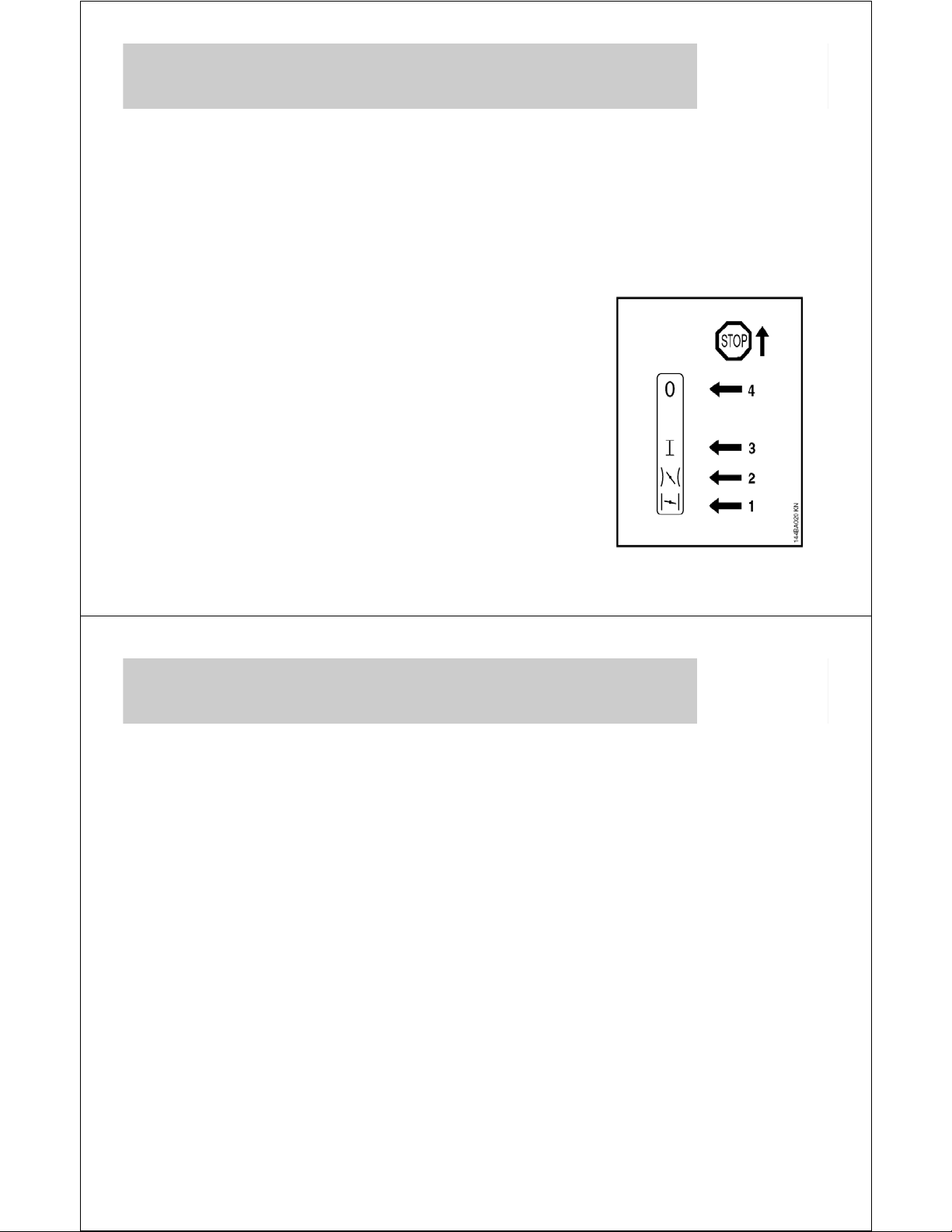
Become Familiar With the Controls
Master Control Lever™
A single lever
operating the choke,
throttle lock and on-off
switch
0 = Off
I = Ignition on
Warm Start
confidential
Cold Start
© STIHL Inc., Virginia Beach, VA 2013 US/STR
Page 3

Starting Features
3
The MS 170 is equipped with a
standard starter mechanism,
and with 2 bar nuts holding the
bar in place
The MS 180 C-B has the
Toolless Quick Chain Adjuster
(QCA) for fast and easy chain
and bar install and adjustment
The MS 180 C-BE also has the
Easy2Start™ starter
mechanism which allows
starting with less effort at a
lower cranking speed
confidential
© STIHL Inc., Virginia Beach, VA 2013 US/STR
Starting Features
The MS 180 C-B has the standard starter mechanism, which
requires a brisk pull on the rope to it’s full extension to start
the engine
The MS 180 C-BE has the Easy2Start™ starter mechanism,
which allows starting by simply pulling out the rope slow and
easy, winding the auxiliary spring which then spins the motor
over to start it
Notice that the MS
180 C-BE has a
deeper recoil
confidential
housing and the
handle extends out
slightly farther for
clearance
© STIHL Inc., Virginia Beach, VA 2013 US/STR
Page 4
© STIHL Inc., Virginia Beach, VA 2013 US/STR
4
confidential
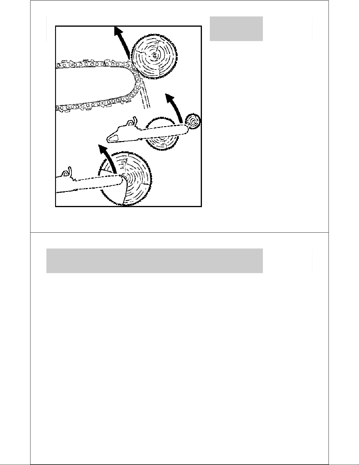
Kickback!!!
Kickback occurs when the
moving saw chain near
the upper quadrant of the
bar nose contacts a solid
object or is pinched
The greater the force of
the kickback reaction, the
more difficult it becomes
for the operator to control
the saw
Chain and Bar Color Code Marking
STIHL saw chain will have a green
or yellow tie strap to indicate if the
chain is low-kickback or other than
low-kickback
The bar will have two green or
yellow dots on the powerhead end
of the bar to identify if the bar is a
reduced kickback bar or not
confidential
© STIHL Inc., Virginia Beach, VA 2013 US/STR
Page 5

Install the Bar and Chain
5
STIHL recommends the use of reduced
kickback bars and low kickback chains on
all STIHL chain saws
Yellow bar and chain combinations are for
trained professionals with extraordinary
cutting needs
Be sure the bar and chain are within the
recommended length for the model of
saw being assembled
Always wear gloves when handling saw
chain to protect your hands from the
sharp cutters
confidential
© STIHL Inc., Virginia Beach, VA 2013 US/STR
Install Bar & Chain: Quick Chain Adjuster
Install the tensioning gear and fasten the screw securely
The bar can be installed with the STIHL logo facing up or
down; periodically the bar should be flipped to spread the
wear over both edges of the bar
confidential
© STIHL Inc., Virginia Beach, VA 2013 US/STR
Page 6

Install Bar & Chain
6
Make sure the cutters on top of the bar are facing away from
the powerhead!
WRONG
WRONG
CORRECT
confidential
© STIHL Inc., Virginia Beach, VA 2013 US/STR
Quick Chain Adjuster (QCA)
The QCA allows the user to adjust the
chain tension without tools
Loosen the wing nut
Rotate the
adjusting wheel
confidential
Tighten the wing nut
© STIHL Inc., Virginia Beach, VA 2013 US/STR
Page 7

Install Bar & Chain
7
confidential
If the saw does not have a QCA simply remove the 2 bar nuts,
install the bar and chain, making sure the adjusting pin is in the
hole in the bar
© STIHL Inc., Virginia Beach, VA 2013 US/STR
Install Bar & Chain
confidential
Install the cover and the 2 nuts leaving them just snug against
the cover
© STIHL Inc., Virginia Beach, VA 2013 US/STR
Page 8

Chain Adjustment
8
The 1130 saws have a front
chain tensioner
Most STIHL chain saws have a
side chain tensioner that is more
convenient to use
Saws come with a combination
wrench, commonly referred to as
a “Scrench”, to make bar and
chain service easy to do
confidential
© STIHL Inc., Virginia Beach, VA 2013 US/STR
Install Bar & Chain
Adjust the chain tension with the “Scrench” by holding up on
the nose of the bar, tightening the chain tension screw, then
tightening the nuts
confidential
© STIHL Inc., Virginia Beach, VA 2013 US/STR
Page 9

Correct Chain Tension
9
With the chain brake
disengaged, pull the
chain through from the
top side and it should
rotate freely without any
slack appearing
If the chain goes from
tight to loose the
sprocket and chain may
not be of the same pitch,
or the sprocket and chain
may have excessive
wear and no longer have
the same pitch
confidential
© STIHL Inc., Virginia Beach, VA 2013 US/STR
Correct Chain Tension
Regardless of bar
length, check for
correct chain tension
by pulling up on the
chain at the center of
the bar
The tension is correct
confidential
when the bottom of the
drive link will just clear
the bar groove
© STIHL Inc., Virginia Beach, VA 2013 US/STR
Page 10

Cutterless Chain for Service
10
For any chain saw, to properly tune the carb or verify running
RPM at idle and wide open throttle a bar and chain should be
installed
Cutterless chains are available to provide a safe way for the
service technician to do this without fear of the chain coming
into contact with anything
confidential
© STIHL Inc., Virginia Beach, VA 2013 US/STR
Chain Brake
confidential
All Current Models of STIHL Chain Saws are Equipped with
the STIHL Quickstop® Chain Braking System
The chain is stopped and locked when the hand guard is
pushed toward the guide bar nose by the left hand – or when
the brake is activated by enough inertia in certain kickback
situations
Brake
Brake
Band
Band
Engaged
Disengaged
© STIHL Inc., Virginia Beach, VA 2013 US/STR
Page 11

Starting the 1130 Saw
11
Fill the tank with 89
octane brand name fuel
with STIHL two-stroke oil
mixed at a 50:1 ratio, or
use STIHL MotoMix
Add bar oil to the oil tank
for chain lubrication
confidential
© STIHL Inc., Virginia Beach, VA 2013 US/STR
Starting the 1130 Saw
Push down on the interlock
on the top of the handle and
then squeeze the throttle all
the way open and hold it
Place the Master Control
confidential
Lever™ in the full choke
position, down to the #1
position
© STIHL Inc., Virginia Beach, VA 2013 US/STR
Page 12
Instruction Manual Directions for Safely
12
Starting a Chain Saw
(Never Drop Start a Chain Saw!)
confidential
© STIHL Inc., Virginia Beach, VA 2013 US/STR
First Time Start-Up
When the engine starts, commonly referred
to as a “false start”, move the Master
Control Lever™ up to #2, to open the
choke and then pull the rope again
The engine should start and run at fast idle
Quickly “blip” the throttle to release the
engine from the fast idle position
confidential
© STIHL Inc., Virginia Beach, VA 2013 US/STR
Page 13
First Time Start-Up
13
If a saw is left in the fast idle position with the chain brake
engaged for even a very short period of time it may overheat
the clutch and chain brake components and possibly ruin the
tank housing as well
To stop the engine raise the Master Control Lever™ to the 0
(off) position, #4 in the picture
confidential
© STIHL Inc., Virginia Beach, VA 2013 US/STR
First Time Start-Up: Warm Up
After the engine has started and the chain brake has been
released, slowly squeeze the throttle about half way open and
then slowly release it back to idle
Do this several times, for at least 20 seconds, to completely
purge any remaining air from the carburetor circuits and to
allow the chain lubrication pump time to prime the system with
bar and chain oil
confidential
Never allow any chain saw engine to run at full throttle without
a load, regardless if it is new or broken-in, for more than a few
seconds
© STIHL Inc., Virginia Beach, VA 2013 US/STR
Page 14

Bar & Chain Oiler Check
14
Carefully hold the
tip of the bar over a
piece of wood or
cardboard
Run the saw at half
throttle and verify
that a line of bar
and chain lubricant
is being slung off
the end of the bar
confidential
© STIHL Inc., Virginia Beach, VA 2013 US/STR
Factory Testing of All STIHL Products
Every engine manufactured by STIHL has been started and
operated in a test cell
The test cell makes carburetor adjustments and verifies
that the engine runs properly at idle, acceleration, and at
full throttle under load
The test cell measures the running performance and
emissions and verifies that they are within acceptable
parameters
confidential
All the dealer needs to do is service the unit and verify it is
ready for the customer to operate it
It is extremely rare that a new unit will need any major
adjustments or repair
© STIHL Inc., Virginia Beach, VA 2013 US/STR
Page 15

Fault Analysis: STIHL Engine Check
15
When a unit is running poorly or not at all, using a systematic
approach to identify any and all faults present will allow the
Service Technician to quickly and efficiently determine what is
wrong
It is just as
important to
know what
faults are not
present as well
as faults that
do need to be
addressed
confidential
© STIHL Inc., Virginia Beach, VA 2013 US/STR
DG Screws
STIHL uses the DG type of
confidential
fastener in manufacturing because
they cut their own threads the first
time they are used
Notice that the ones holding into
plastic have a different pitch and
profile than the ones that hold into
For Plastic
For Metal
metal
It is imperative that the Service Technician keep track of which
screw is which and not screw them into the wrong base
material or the threads will be damaged
It is also best practice that when starting a DG screw into the
hole, slowly rotate it backwards until it “clicks” to index the
threads, then turn it clockwise to tighten it
© STIHL Inc., Virginia Beach, VA 2013 US/STR
Page 16

1. Deflectors, Shrouds, Covers, Fasteners
16
Visually look the unit over for damage, missing items, loose
fasteners, or anything else that is obvious
Damaged shroud may be a
safety hazard for the operator
Operated without
an air filter or cover
confidential
© STIHL Inc., Virginia Beach, VA 2013 US/STR
2. Warning Labels
Verify that warning labels
are present and readable
On a chain saw the only
label the service technician
should be concerned with
is the one on the chain
brake handle
If this label is damaged or
worn away, a universal
confidential
replacement label is
available from STIHL
White Chain Saw Label:
0000 967 3613
© STIHL Inc., Virginia Beach, VA 2013 US/STR
Page 17

3. Cutting Attachment
17
Note type and condition
Inspect for wear or damage
Bar, chain, and sprocket
within wear limits
confidential
© STIHL Inc., Virginia Beach, VA 2013 US/STR
3. Cutting Attachment 4. Belt Tension
If the unit is a trimmer or a concrete saw:
Tap head eyelets worn, spool worn, retainer secure
Belt tension correct; belt worn or frayed
confidential
© STIHL Inc., Virginia Beach, VA 2013 US/STR
Page 18

5. Operator Controls
18
The interlock should
be sticking up out of
the handle, and it
must be depressed
flush with the handle
before the throttle
trigger will move
Be sure the throttle
moves freely
confidential
© STIHL Inc., Virginia Beach, VA 2013 US/STR
5. Operator Controls
The throttle must be squeezed all the way open before the
Master Control Lever™ can be actuated to the full choke
position, then release the throttle and the Master Control
Lever™ should stay in the choke position
confidential
© STIHL Inc., Virginia Beach, VA 2013 US/STR
Page 19

5. Operator Controls
19
Now raise the Master
Control Lever™ up one
notch with your thumb, and
it should stay in the warm
start, half choke position
Now squeeze the trigger
and it should snap up to the
I position automatically
confidential
© STIHL Inc., Virginia Beach, VA 2013 US/STR
5. Operator Controls
Finally the Master
Control Lever™
should easily slide up
to the O position
Any problem with the
Master Control
confidential
Lever™ should be
noted for repair
© STIHL Inc., Virginia Beach, VA 2013 US/STR
Page 20

5. Operator Controls
20
When the chain
brake handle is
actuated back
and forth, there
should be an
audible “click”
In the forward
position the
sprocket must
not turn
In the back
position the
sprocket must
spin easily
confidential
© STIHL Inc., Virginia Beach, VA 2013 US/STR
6. Verify Anti-vibration Components
Most STIHL chain saws and line
trimmers have an anti-vibration
system that should be inspected for
wear and damage
Some models do not have any anti-
vibration components so this step
would not apply
confidential
© STIHL Inc., Virginia Beach, VA 2013 US/STR
Page 21

6. Verify Anti-vibration Components
21
Hold the bumper spike
against the edge of the
workbench and put
pressure against the
handle assemble
There should be strong
resistance to movement
but there should be
some “give” to the antivibe rubber bushings
There should not be any
looseness to the handle
assembly
confidential
© STIHL Inc., Virginia Beach, VA 2013 US/STR
7. Inspect Starter System
Inspect rope, handle, and eyelet for wear or damage
Pull the rope to it’s full extended length and be sure it is
not about to break at the very end
confidential
© STIHL Inc., Virginia Beach, VA 2013 US/STR
Page 22

8. Inspect Air Filter 9. Inspect Air Filter Housing
22
Remove cover and the top
of the filter is the clean side
There should not be dirt or
debris on this side of the
filter or down in the throat of
the air intake
Remove the filter and the
bottom side is the dirty side
There should be a pinch
mark all the way around the
edge of the filter to seal it
Verify that the housing is not
cracked or damaged
confidential
© STIHL Inc., Virginia Beach, VA 2013 US/STR
10. Carburetor Mixture Screws
Most STIHL products have
mixture adjustment screws on
the carburetor and will be
equipped with a limiter cap on
the H mixture screw and may
have one on the L screw also
The limiter cap allows the
operator to adjust the carb
leaner only to compensate
for operation in high
altitude
confidential
If a cap is missing it should
be considered as a fault and
it is possible the screw may
be set too lean
© STIHL Inc., Virginia Beach, VA 2013 US/STR
L mixture screw with
cone to guide the
screwdriver in place
H mixture screw
with limiter cap in
the up, or released
position to allow the
technician to make
adjustments
Page 23

10. Carburetor Mixture Screws
23
The 1130 saws do not have
mixture screws or limiter caps
Notice that the H and L holes are
not threaded and are blocked off
internally
The only adjustment on a 1130
saw is to set the idle speed with
this screw
It also makes slight mixture
adjustments as the idle speed is
tuned
This carburetor uses a fixed
orifice jet to regulate the amount
of fuel available to the engine
confidential
and is not adjustable
© STIHL Inc., Virginia Beach, VA 2013 US/STR
10. Carburetor Screw Settings
Limiter caps can be removed by
the service technician for carb
service
Removal of this style of limiter
cap is done with the 5910 890
4501 tool
Anytime a cap is removed best
practice is to replace it with a
new one
confidential
4229 121 2701
On the 1130 saws this step
does not apply
© STIHL Inc., Virginia Beach, VA 2013 US/STR
Page 24

Hose Removal
24
The 5910 890 4501 tool also works well to remove fuel,
impulse, or vent hoses
Use a side to side rocking
motion while pushing against
the hose to walk it off of the
fitting
confidential
© STIHL Inc., Virginia Beach, VA 2013 US/STR
11. Spark Plug Connection
Use a twisting motion to remove the spark plug connection
and be careful not to pull the clip out of the high tension
lead
Inspect it for damage, hardness or cracks
confidential
© STIHL Inc., Virginia Beach, VA 2013 US/STR
Page 25

12. Spark Test
25
Connect a spark
tester and pull the
rope through as if
trying to start the
engine
If no spark is present
try again with a new
plug
A fouled or
defective spark
plug may not show
spark on the tester
even if the ignition
system is OK
confidential
© STIHL Inc., Virginia Beach, VA 2013 US/STR
12. Spark Test
If there is still a no
spark condition with a
new plug, carefully
disconnect the ground
wire from the terminal
on the ignition module
and now see if spark
is present
If there is no spark the
confidential
module is faulty
If there is spark the
stop circuit is faulty
© STIHL Inc., Virginia Beach, VA 2013 US/STR
Page 26

12. Ignition Shut-Off Function
26
If spark is present then place the Master Control Lever™ in
the off position and pull the rope through and verify that no
spark is present
This verifies that the stop switch and connecting wiring is in
order
confidential
© STIHL Inc., Virginia Beach, VA 2013 US/STR
13. Spark Plug
Verify that the correct plug is installed for an 1130 saw:
Bosch WSR6F STIHL Part Number 1110 400 7005
NGK BPMR7A STIHL Part Number 0000 400 7000
Other units may use a different part number with a different
heat range, so always look it up!
Set all STIHL spark plugs at .020”
confidential
© STIHL Inc., Virginia Beach, VA 2013 US/STR
Page 27

13. Spark Plug Appearance
27
Normal color,
normal electrode
wear due to high
run time
Normal color and
wear
confidential
Heavy
carbon buildup and oil
fouled
Mix ratio
incorrect.
Carbon buildup
due to high run
time
Both of these
plugs have served
their useful life
© STIHL Inc., Virginia Beach, VA 2013 US/STR
14. Muffler
Remove the 2 muffler nuts and
Black, sooty
appearance
Caused by
rich fuel/air
mixture
confidential
deflector plate and inspect the
spark arrester screen
It must be present for all hand
held engines used in the United
States
The screen may be blocked
with carbon deposits
If necessary shine a light
through the screen to verify
© STIHL Inc., Virginia Beach, VA 2013 US/STR
Page 28

Remove Starter Housing
28
Remove fuel and oil tank caps
Rock the cap retainer to the side
Remove starter housing
Reinstall the caps if necessary to prevent fuel or oil from
running out on the work area
© STIHL Inc., Virginia Beach, VA 2013 US/STR
confidential
15. Cylinder Leak Down Test
This test typically is not
necessary on a two-stroke
engine but can be done to verify
how well the rings are sealing
with the flywheel blocked so the
piston is slightly down from TDC
A leak down test should always
be done on a four-stroke engine
because the piston and rings
cannot be observed visually
The leak down test also verifies
that the intake and exhaust
valves are sealing properly
confidential
© STIHL Inc., Virginia Beach, VA 2013 US/STR
Page 29

16. Inspect Exhaust Port and Piston
29
With the muffler removed use
a flashlight and look through
the exhaust port to be sure
the port is not clogged up
with carbon deposits
Move the piston up and down
and inspect the surface of the
piston skirt for scoring or
damage
A piston in good condition
will still have the radial
machine marks across the
skirt indicating little or no
wear
confidential
© STIHL Inc., Virginia Beach, VA 2013 US/STR
16. Inspect Exhaust Port and Piston
Spray some lubricant on
the rings and when the
flywheel is turned back
and forth slightly it will be
apparent if the rings are
free in the lands
Lower the piston to BDC
confidential
Inspect the intake side of
the cylinder wall for wear
or damage
© STIHL Inc., Virginia Beach, VA 2013 US/STR
Page 30

17. Cooling System
30
Verify that the cooling fins are in good condition and that the
air path to the flywheel and through the engine from the
flywheel is not blocked or restricted in any way
Verify that the flywheel fins are in good condition
confidential
© STIHL Inc., Virginia Beach, VA 2013 US/STR
18. Magneto Air Gap
Line up the pole shoes in the
flywheel with the magneto
Observe the gap between the
ignition module and the
flywheel
The specification is .008”
It is not absolutely
necessary to measure this
with a gauge, just be sure
confidential
the flywheel is not rubbing
on the module and that the
gap does not look
excessively wide
© STIHL Inc., Virginia Beach, VA 2013 US/STR
Page 31

19. Fuel Tank
31
confidential
If the tank is empty look down in the tank to see if it appears
contaminated with debris or anything else that shouldn’t be
there
If the unit has fuel in it carefully remove the cap and wave your
hand over the opening while smelling for a sour odor that may
indicate old stale fuel
© STIHL Inc., Virginia Beach, VA 2013 US/STR
19. Fuel Tank
If fuel is present carefully pour the fuel out in a pan and see if
there is trash or debris, or any evidence of other contaminants
such as water in the fuel
This sample is
contaminated with
water and debris
Dispose of fuel properly
confidential
© STIHL Inc., Virginia Beach, VA 2013 US/STR
Page 32

20. Fuel Filter
32
confidential
Use the 5910 893 880 hook tool to fish the fuel filter out of the
tank for inspection
The filter body screen should be clear and in good condition,
and the element may have oil staining but should not be dark
or fouled or have any kind of coating on it
© STIHL Inc., Virginia Beach, VA 2013 US/STR
Pressure Vacuum Tester
0000 850 1300 Pump
With the knurled ring to
the right the gauge
indicates pressure
With the knurled ring to
the left the gauge
confidential
indicates vacuum
© STIHL Inc., Virginia Beach, VA 2013 US/STR
Page 33

20. Fuel Filter
33
It is a good idea to backflow a fuel filter with the pressure
pump to verify that it is not restricted
Hook up the tester and place the filter on a towel and pump
the tester 2 times
No pressure should build up and if the filter is wet with fuel
it should clearly flow out
confidential
© STIHL Inc., Virginia Beach, VA 2013 US/STR
21. Pressure Test Fuel Line
confidential
Connect the pressure tester to the fuel line where the filter was
removed and gently pump it up no higher than 10 PSI
If it holds steady then the fuel line is OK, and the carb itself
passes the pressure test
If the gauge does not
hold then either the fuel
line or the carb may be
leaking, so isolate the
fuel line and test it by
itself to determine
where the fault is
© STIHL Inc., Virginia Beach, VA 2013 US/STR
Page 34

Remove Carb
34
Hold the choke shutter closed and carefully remove the link
confidential
© STIHL Inc., Virginia Beach, VA 2013 US/STR
Remove Carb
Carefully slide the fuel line off of the fitting
confidential
© STIHL Inc., Virginia Beach, VA 2013 US/STR
Page 35

Remove Carb
35
Hold the throttle wide open and carefully remove the link
confidential
© STIHL Inc., Virginia Beach, VA 2013 US/STR
Remove Carb
Gently pry the Master Control Lever™ up on the left side
confidential
© STIHL Inc., Virginia Beach, VA 2013 US/STR
Page 36

Remove Carb
36
Slide the Master Control Lever™ to the left and let it hang
out of the way by the ground wire
confidential
© STIHL Inc., Virginia Beach, VA 2013 US/STR
Remove Carb
Hold the fuel line down out of the way and slide the carb off
of the studs
confidential
© STIHL Inc., Virginia Beach, VA 2013 US/STR
Page 37

21. Pressure Test Fuel Line
37
confidential
To test the fuel line by itself, plug one end and test through the
other
It should hold steady at 10 PSI
© STIHL Inc., Virginia Beach, VA 2013 US/STR
22. Pressure Test Tank
Be sure there is no fuel
in the tank before
applying any pressure to
the fuel tank!
The pressure test
verifies that the tank
does not have a leak in
any location, such as a
grommet, seam, cap or
confidential
hose
Apply about 8 PSI max and it must hold steady
If it leaks down at all use soapy water in a spray bottle
to locate where the leak is
© STIHL Inc., Virginia Beach, VA 2013 US/STR
Page 38

23. Vacuum Test Tank Vent
38
Reverse the tester into
vacuum mode and pump
hard and fast to see the
needle indicates that
some negative pressure
is present in the tank
Stop pumping and watch
the gauge and the
needle should move
back up towards zero
rapidly
If the needle does not
leak back to zero quickly
the tank vent must be
replaced and then re-test
confidential
© STIHL Inc., Virginia Beach, VA 2013 US/STR
24. Inspect Intake Side Of Piston
With the carb removed
look through the inlet port
and rotate the crankshaft
to inspect the intake side
of the piston
The machine marks
should be present on a
piston in good condition
Scoring or a dull gray
appearance would
indicate lack of
lubrication, dirt ingestion,
or possibly other
problems that would
prevent the engine from
running properly
confidential
© STIHL Inc., Virginia Beach, VA 2013 US/STR
Page 39

25. Impulse Signal Present
39
Most two-stroke engines have a
passageway between the
crankcase and the fuel pump side of
the carburetor to cause the fuel
pump diaphragm to flex back and
forth with the pressure/vacuum that
is created by the piston moving up
and down
It is rare that there is no impulse
signal, but always verify that it is
present because no impulse signal
will cause a hard to diagnose,
unusual running behavior that will
appear to be carburetor related
confidential
For this blower engine the
impulse signal comes out
through the flange here:
© STIHL Inc., Virginia Beach, VA 2013 US/STR
25. Impulse Signal Present
confidential
For the 1130 saw, remove the white plastic sealing ring, use
the tapered adapter and connect the tester to the impulse port
By hand, rotate the flywheel back and forth and the needle on
the gauge should bounce back and forth indicating the
impulse signal is present
© STIHL Inc., Virginia Beach, VA 2013 US/STR
Page 40

26. Vacuum and Pressure Test of Crankcase
40
confidential
A two-stroke engine needs an air tight crankcase since the air
fuel mix is coming through the crankcase on the way to the
combustion chamber
Test to verify that there are no leaks at places like gaskets or
RTV silicone sealed mating surfaces, and that crankshaft seals
are not leaking under pressure or vacuum
Block off the exhaust port
by slipping a rubber block
off plate in between the
cylinder and the adapter
plate, then install spacers
and snug up the nuts
while pulling the rubber up
to get a complete seal
© STIHL Inc., Virginia Beach, VA 2013 US/STR
26. Vacuum and Pressure Test of Crankcase
The Service Manual for each
model describes how to do
this test and gives the part
number for the adapters
For the 1130 saw the special
adapter for the carb side is
part number 1118 850 4200
confidential
Be sure the spark plug is
installed and tight
© STIHL Inc., Virginia Beach, VA 2013 US/STR
Page 41

26. Vacuum and Pressure Test of Crankcase
41
Use the tester to pull a 0.5 bar vacuum; it should hold steady
or not leak back to 0.3 bar within 20 seconds
Rotate the crankshaft back and forth while the crankcase is
under vacuum to verify that the seals are holding properly
Pump 0.5 bar of pressure into the engine and it should hold
steady for at least 20 seconds
confidential
© STIHL Inc., Virginia Beach, VA 2013 US/STR
Pressure Test Results
confidential
If the unit fails the pressure test check obvious things first, such
as the rubber sealing plate on the exhaust and the spark plug,
by spraying with soapy water and looking for bubbles
If they are sealing properly then the engine may need to be
taken apart far enough to be able to check the crankshaft seals
and the seal between the cylinder and the crankcase
If an engine leaks under vacuum but holds under pressure it is
most likely a crankshaft seal
© STIHL Inc., Virginia Beach, VA 2013 US/STR
Page 42

27. Crankshaft and Bearing Condition
42
See if the flywheel moves in and out or up and down
There should not be any loose play in the crankshaft
bearings
confidential
© STIHL Inc., Virginia Beach, VA 2013 US/STR
28. Carburetor
confidential
Pressure test the carb no higher than 10 PSI and it should hold
steady
Open and close the butterfly and it should open smoothly
Verify that the throttle shaft does not have any excessive side
to side play
Inspect the carb for any physical damage
© STIHL Inc., Virginia Beach, VA 2013 US/STR
Page 43

29. Other Observations; Final Running
43
This is where any other observations about the unit not
specifically covered by one of the numbered items on the
STIHL Engine Check can be recorded
Once repairs have
been made the last
part of the STIHL
Engine Check
document can be used
as a quality control
check to be sure the
engine starts easily
and is running to
specification
confidential
© STIHL Inc., Virginia Beach, VA 2013 US/STR
Final Check: Roll Out Test
With the engine warmed
up and idling, and the
chain brake engaged on
a saw, slowly roll the
engine over so one side
faces the ground
Now roll it back upright,
then roll the other side
towards the ground
Idle RPM should not
change more than 200300 RPM
confidential
If the idle changes the
engine may have an air
leak or other fault
© STIHL Inc., Virginia Beach, VA 2013 US/STR
Page 44

This presentation has been prepared by:
44
Eddie Anderson
Technical Training Supervisor
STIHL Inc.
Virginia Beach, VA
eddie.anderson@stihl.us
© STIHL Inc., Virginia Beach, VA 2013 US/STR
confidential
 Loading...