

Page 1
{
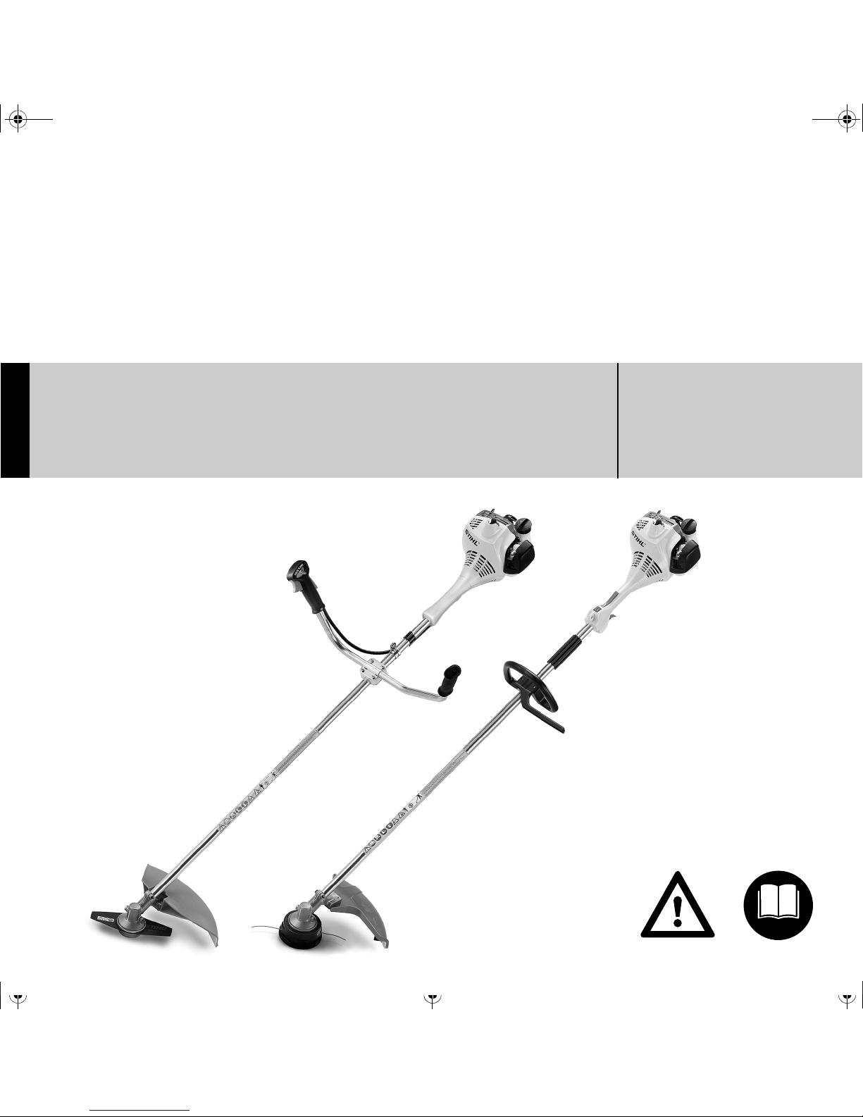
STIHL FS 55
Instruction Manual
Notice d’emploi
Page 2

G Instruction Manual
1 - 38
F Notice d’emploi
39 - 79
Page 3

Original Instruction ManualPrinted on chlorine-free paper
Printing inks contain vegetable oils, paper can be recycled.
© ANDREAS STIHL AG & Co. KG, 2011
0458-233-8221-C. M7.C11.CP.
0000002417_006_GB
FS 55, FS 55 C, FS 55 R, FS 55 RC
English
1
{
Contents
Dear Customer,
Thank you for choosing a quality
engineered STIHL product.
This machine has been built using
modern production techniques and
comprehensive quality assurance.
Every effort has been made to ensure
your satisfaction and troublefree use
of the machine.
Please contact your dealer or our
sales company if you have any
queries concerning your machine.
Your
Hans Peter Stihl
Guide to Using this Manual 2
Safety Precautions and Working
Techniques 2
Approved Combinations of Cutting
Attachment, Deflector, Handle and
Harness 11
Mounting the Bike Handle 12
Mounting the Loop Handle 13
Fitting the Carrying Ring 15
Mounting the Deflector 15
Mounting the Cutting Attachment 16
Fuel 18
Fueling 19
Fitting the Harness 20
Balancing the Trimmer/Brushcutter 20
Starting / Stopping the Engine 21
Operating Instructions 25
Cleaning the Air Filter 25
Engine Management 26
Adjusting the Carburetor 26
Spark Plug 28
Engine Running Behavior 29
Rewind Starter 29
Storing the Machine 29
Sharpening Metal Cutting Blades 30
Inspections and Maintenance by
Dealer 30
Maintenance and Care 31
Main Parts 33
Specifications 35
Special Accessories 36
Maintenance and Repairs 36
STIHL Limited Emission Control
Warranty Statement 37
Page 4
FS 55, FS 55 C, FS 55 R, FS 55 RC
English
2
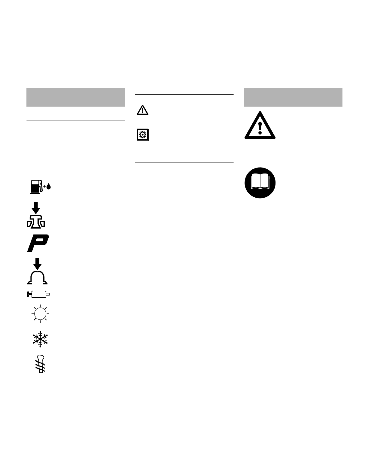
Pictograms
The meanings of the pictograms
attached to the machine are explained in
this manual.
Depending on the model concerned, the
following pictograms may be attached to
your machine.
Symbols in text
Engineering improvements
STIHL's philosophy is to continually
improve all of its products. For this
reason we may modify the design,
engineering and appearance of our
products periodically.
Therefore, some changes, modifications
and improvements may not be covered
in this manual.
Observe all applicable local safety
regulations, standards and ordinances.
If you have not used this type of power
tool before: Have your dealer or other
experienced user show you how to
operate your power tool or attend a
special course in its operation.
Minors should never be allowed to use a
power tool.
Keep bystanders, especially children,
and animals away from the work area.
When the power tool is not in use, shut it
off so that it does not endanger others.
Secure it against unauthorized use.
The user is responsible for avoiding
injury to third parties or damage to their
property.
Guide to Using this Manual
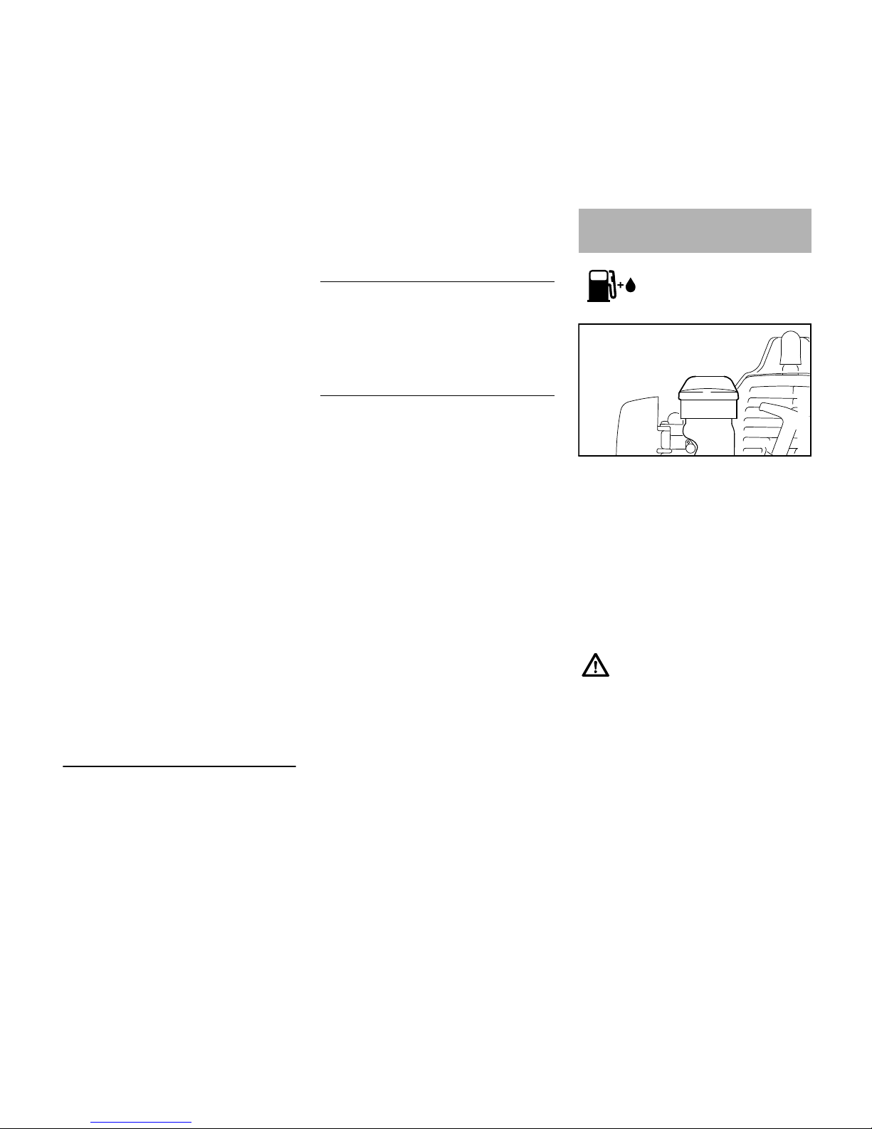
Fuel tank; fuel mixture of
gasoline and engine oil
Operate decompression
valve
Manual fuel pump
Operate manual fuel
pump
Tube of grease
Intake air: Summer
operation
Intake air: Winter
operation
Handle heating
Warning where there is a risk of
an accident or personal injury or
serious damage to property.
Caution where there is a risk of
damaging the machine or its
individual components.
Safety Precautions and
Working Techniques
Some special safety precautions must be
observed to reduce the
risk of personal injury
when operating this
power tool because of the
very high speed of its cutting attachment.
It is important you read
and understand the
instruction manual before
using your power tool for
the first time and keep
the manual in a safe
place for future reference. Non-observance of
the safety precautions
may result in serious or
even fatal injury.
Page 5
FS 55, FS 55 C, FS 55 R, FS 55 RC
English
3
Do not lend or rent your power tool
without the instruction manual. Be sure
that anyone using it understands the
information contained in this manual.
The use of noise emitting power tools
may be restricted to certain times by
national or local regulations.
To operate the power tool you must be
rested, in good physical condition and
mental health.
If you have any condition that might be
aggravated by strenuous work, check
with your doctor before operating a
power tool.
Persons with pacemakers only: The
ignition system of your power tool
produces an electromagnetic field of a
very low intensity. This field may
interfere with some pacemakers. To
reduce health risks, STIHL recommends
that persons with pacemakers consult
their physician and the pacemaker
manufacturer before operating this tool.
Do not operate the power tool if you are
under the influence of any substance
(drugs, alcohol) which might impair
vision, dexterity or judgment.
Depending on the cutting attachment
fitted, use your power tool only for
cutting grass, wild growth, shrubs,
scrub, bushes, small diameter trees and
similar materials.
Do not use your power tool for any other
purpose since this may result in
accidents.
Only use cutting attachments and
accessories that are explicity approved
for this power tool model by STIHL or
are technically identical. If you have any
questions in this respect, consult a
servicing dealer. Use only high quality
parts and accessories in order to avoid
the risk of accidents and damage to the
machine.
STIHL recommends the use of original
STIHL replacement parts. They are
specifically designed to match your
model and meet your performance
requirements.
Never attempt to modify your power tool
in any way since this may increase the
risk of personal injury. STIHL excludes
all liability for personal injury and
damage to property caused while using
unauthorized attachments.
Do not use a pressure washer to clean
the unit. The solid jet of water may
damage parts of the unit.
The deflector on this power tool cannot
protect the operator from all objects
thrown by the cutting attachment
(stones, glass, wire, etc.). Such objects
may ricochet and then hit the operator.
Clothing and Equipment
Wear proper protective clothing and
equipment.
Avoid clothing that could get caught on
branches or brush or moving parts of the
machine. Do not wear a scarf, necktie or
jewelry. Tie up and confine long hair
(e.g. with a hair net, cap, hard hat, etc.).
Sturdy shoes with non-slip soles may be
worn as an alternative only when using
mowing heads.
A face shield alone does not provide
adequate eye protection.
Wear hearing protection, e.g. earplugs
or ear muffs.
STIHL offers a comprehensive range of
personal protective clothing and
equipment.
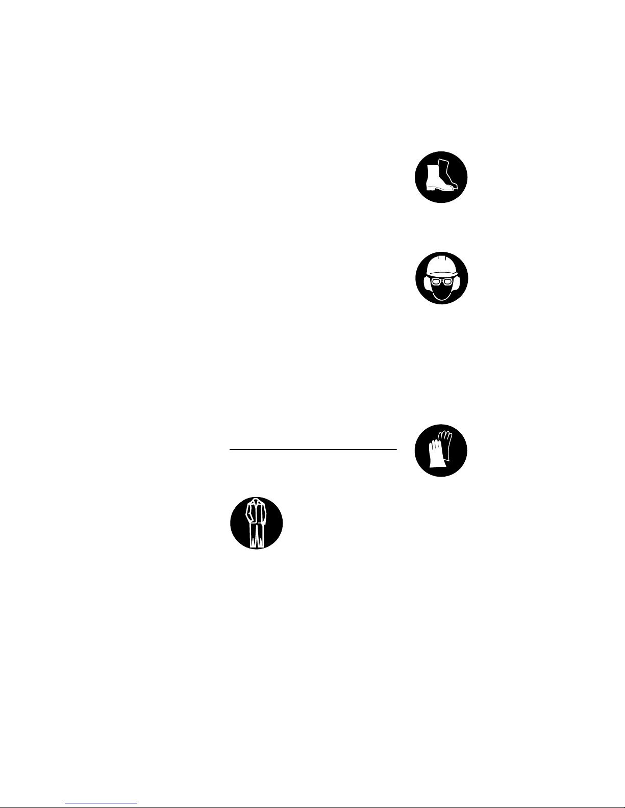
Clothing must be sturdy
but allow complete freedom of movement. Wear
snug-fitting clothing, an
overall and jacket combination, do not wear a
work coat.
Wear steel-toed safety
boots with non-slip soles.
Wear a safety hard hat
for thinning operations,
when working in high
scrub and where there is
a danger of head injuries
from falling objects. To
reduce the risk of injury
from thrown objects,
always wear a face shield
and safety glasses.
Wear heavy-duty gloves.
Page 6
FS 55, FS 55 C, FS 55 R, FS 55 RC
English
4
Transporting the Power Tool
Always turn off the engine.
Carry the unit hanging from the shoulder
strap or properly balanced by the drive
tube. Fit transport guard on metal cutting
attachments to avoid the risk of injury
from blade contact
Transporting in a vehicle: Properly
secure your power tool to prevent
turnover, fuel spillage and damage.
Fueling
Always shut off the engine before
refueling.
Do not fuel a hot engine – fuel may spill
and cause a fire.
Open the fuel cap carefully to allow any
pressure build-up in the tank to release
slowly and avoid fuel spillage.
Fuel your power tool only in wellventilated areas. If you spill fuel, wipe
the machine immediately – if fuel gets on
your clothing, change immediately.
Your power tool comes standard with
either a screw-type or bayonet-type fuel
cap.
This reduces the risk of unit vibrations
causing the fuel cap to loosen or come
off and spill quantities of fuel.
To reduce the risk of serious or fatal
burn injuries, check for fuel leakage. If
fuel leakage is found, do not start or run
the engine until leak is fixed.
Before starting
Check that your power tool is properly
assembled and in good condition – refer
to appropriate chapters in the instruction
manual.
– Use only an approved combination
of cutting attachment, deflector,
handle and harness. All parts must
be assembled properly and
securely.
– Slide control / stop switch must
move easily to STOP or 0
– Smooth action of throttle trigger
interlock (if fitted) and throttle trigger
– the throttle trigger must return
automatically to the idle position.
– Check that the spark plug boot is
secure – a loose boot may cause
arcing that could ignite combustible
fumes and cause a fire.
– Cutting tool or attachment: Check
for correct and secure assembly
and good condition.
– Check protective devices (e.g.
deflector for cutting tool, rider plate)
for damage or wear. Always replace
damaged parts. Do not operate your
machine with a damaged deflector
or worn rider plate (lettering and
arrows no longer legible).
– Never attempt to modify the controls
or the safety devices in any way.
– Keep the handles dry and clean –
free from oil and dirt – for safe
control of the power tool.
– Adjust the harness and handle(s) to
suit your height and reach. See
chapters on "Fitting the Harness"
and "Balancing the
Trimmer/Brushcutter".
To reduce the risk of personal injury,
do not operate your power tool if it is
damaged or not properly assembled.
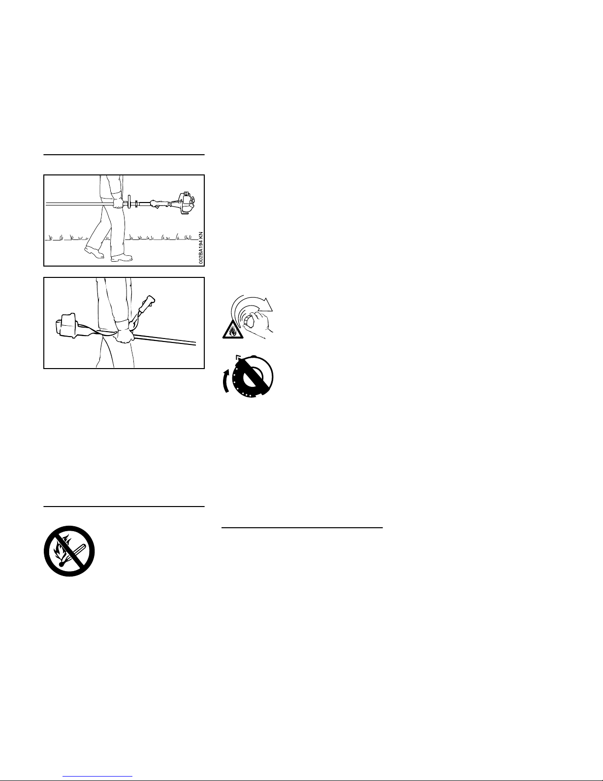
Gasoline is an
extremely flammable
fuel. Keep clear of naked
flames. Do not spill any
fuel – do not smoke.
002BA079 KN
After fueling, tighten
down the screw-type fuel
cap as securely as
possible.
Insert the fuel cap with
hinged grip (bayonet-type
cap) correctly in the
opening, turn it clockwise
as far as stop and fold the
grip down.
Page 7
FS 55, FS 55 C, FS 55 R, FS 55 RC
English
5
If you use a shoulder strap or full
harness: Practise removing and putting
down the machine as you would in an
emergency. To avoid damage, do not
throw the machine to the ground when
practising.
Starting the engine
Start the engine at least 3 meters from
the fueling spot, outdoors only.
Place the unit on firm ground in an open
area. Make sure you have good balance
and secure footing. Hold the unit
securely. The cutting attachment must
be clear of the ground and all other
obstructions because it may begin to run
when the engine starts.
Your power tool is a one-person unit. To
reduce the risk of injury from thrown
objects, do not allow other persons
within a radius of 15 meters of your own
position – even when starting.
Check idle speed setting: The cutting
attachment must not rotate when the
engine is idling with the throttle trigger
released.
To reduce the risk of fire, keep hot
exhaust gases and hot muffler away
from easily combustible materials (e.g.
wood chips, bark, dry grass, fuel).
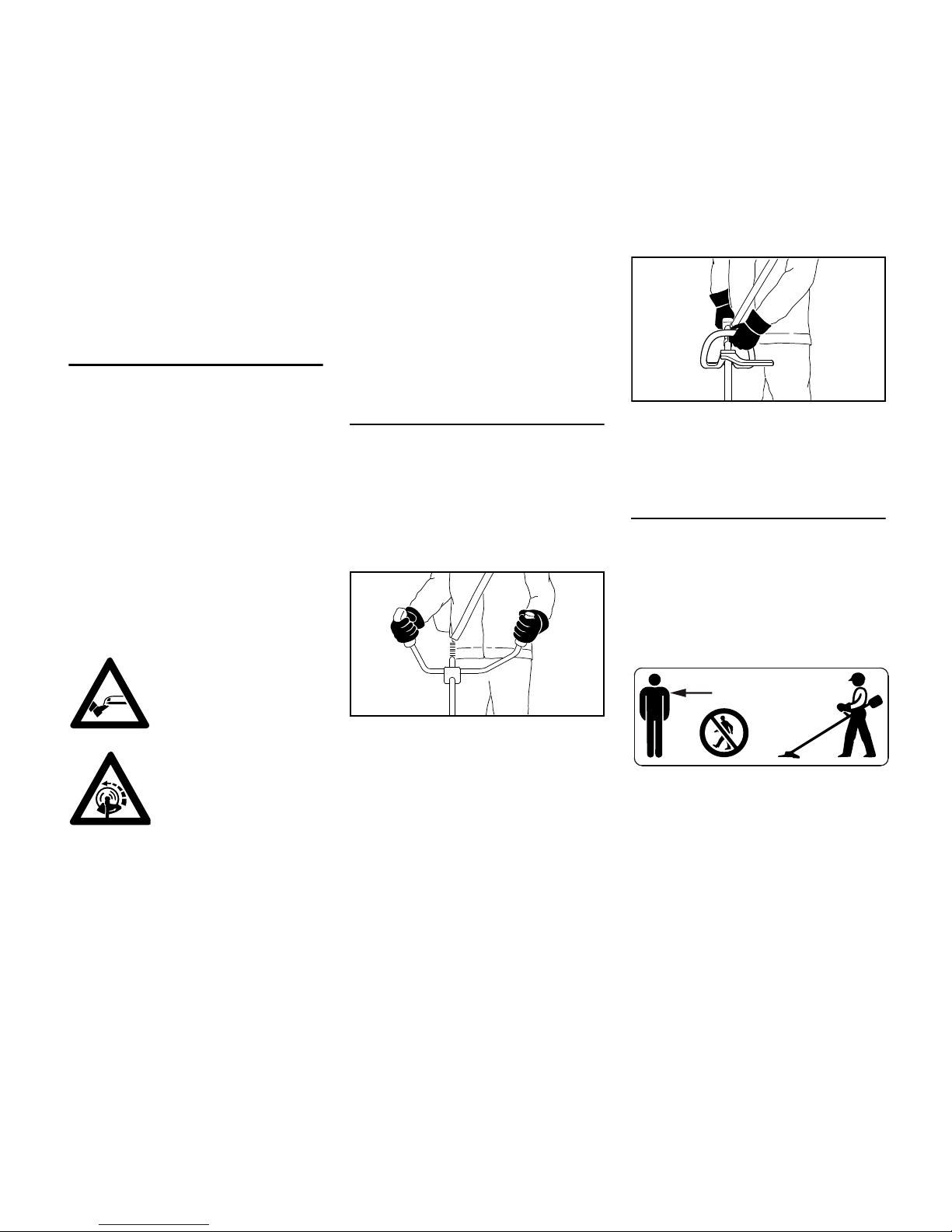
Holding and Controlling the Power
Tool
Always hold the unit firmly with both
hands on the handles.
Make sure you always have good
balance and secure footing.
Models with bike handle
Right handle on control handle, left hand
on left handle.
Models with loop handle
On units with a loop handle and barrier
bar, left hand on loop handle, right hand
on control handle, even if you are lefthanded.
During Operation
Make sure you always have good
balance and secure footing.
In the event of impending danger or in
an emergency, switch off the engine
immediately by moving the slide control
/ stop switch to STOP or 0.
To reduce the risk of personal injury ,
do not allow any other persons within a
radius of 15 meters of your own position.
To reduce the risk of damage to
property, also maintain this distance
from other objects (vehicles, windows).
The correct engine idle speed is
important to ensure that the cutting
attachment stops rotating when you let
go of the throttle trigger.
To reduce the risk of
injury, avoid contact with
the cutting attachment.
Do not drop start the
power tool – start the
engine as described in
the instruction manual.
Note that the cutting
attachment continues to
run for a short period
after you let go of the
throttle trigger – fly-
wheel effect.
002BA055 KN
002BA080 KN
15m (50ft)
Page 8

FS 55, FS 55 C, FS 55 R, FS 55 RC
English
6
Check and correct the idle speed setting
at regular intervals. If the cutting
attachment still rotates at idle speed,
have your dealer make proper
adjustments or repairs. STIHL
recommends a STIHL servicing dealer.
Take special care in slippery conditions
– damp, snow, ice, on slopes or uneven
ground.
Watch out for obstacles: Roots, tree
stumps or holes which could cause you
to trip or stumble.
Always stand on the ground while
working, never on a ladder, work
platform or any other insecure support.
Be particularly alert and cautious when
wearing hearing protection because
your ability to hear warnings (shouts,
alarms, etc.) is restricted.
To reduce the risk of accidents, take a
break in good time to avoid tiredness or
exhaustion.
Work calmly and carefully – in daylight
conditions and only when visibility is
good. Stay alert so as not to endanger
others.
To reduce the risk of serious or fatal
injury from breathing toxic fumes,
ensure proper ventilation when working
in trenches, hollows or other confined
locations.
To reduce the risk of accidents, stop
work immediately in the event of
nausea, headache, visual disturbances
(e.g. reduced field of vision), problems
with hearing, dizziness, deterioration in
ability to concentrate. Apart from other
possibilities, these symptoms may be
caused by an excessively high
concentration of exhaust gases in the
work area.
Operate your power tool so that it
produces a minimum of noise and
emissions – do not run the engine
unnecessarily, accelerate the engine
only for cutting.
To reduce the risk of fire, do not
smoke while operating or standing near
your power tool. Note that combustible
fuel vapor may escape from the fuel
system.
The dusts, vapor and smoke produced
during operation may be dangerous to
health. If the work area is very dusty or
smoky, wear a respirator.
If your power tool is subjected to
unusually high loads for which it was not
designed (e.g. heavy impact or a fall),
always check that it is in good condition
before continuing work – see also
"Before Starting".
Check the fuel system in particular for
leaks and make sure the safety devices
are working properly. Do not continue
operating your power tool if it is
damaged. In case of doubt, have the
machine checked by your servicing
dealer.
Do not operate your power tool with the
starting throttle lock engaged – engine
speed cannot be controlled in this
position.
Special care must be taken when
working in difficult, over-grown terrain.
When cutting high scrub, under bushes
and hedges: Keep cutting tool at
minimum height of 15 cm to avoid
harming small animals.
Always shut off the engine before
leaving the unit unattended.
Check the cutting attachment at regular
short intervals during operation or
immediately if there is a noticeable
change in cutting behavior:
Your power tool produces
toxic exhaust fumes as
soon as the engine is
running. These fumes
may be colorless and
odorless and contain
unburned hydrocarbons
and benzol. Never run
the engine indoors or in
poorly ventilated locations, even if your model
is equipped with a catalytic converter.
To reduce the risk
of injury from
thrown objects,
never operate the
unit without the
proper deflector for
the type of cutting
attachment being
used.
Inspect the work area:
Stones, pieces of metal
or other solid objects can
be thrown and cause personal injury or damage
the cutting attachment
and property (e.g. parked
vehicles, windows).
Page 9

FS 55, FS 55 C, FS 55 R, FS 55 RC
English
7
– Turn off the engine. Hold the unit
firmly and wait for the cutting
attachment to come to a standstill.
– Check condition and tightness, look
for cracks.
– Check sharpness.
– Replace damaged or dull cutting
attachments immediately, even if
they have only superficial cracks.
Clean grass and plant residue off the
cutting attachment mounting at regular
intervals – remove any build up of
material from the cutting attachment and
deflector.
To reduce the risk of injury, shut off
the engine before replacing the cutting
attachment.
Do not continue using or attempt to
repair damaged or cracked cutting
attachments by welding, straightening or
modifying the shape (out of balance).
This may cause parts of the cutting
attachment to come off and hit the
operator or bystanders at high speed
and result in serious or fatal injuries.
When using mowing heads
Equip the deflector with the additional
components specified in the instruction
manual.
Use only the deflector with properly
mounted line limiting blade to ensure the
mowing lines are automatically trimmed
to the approved length.
To reduce the risk of injury, always
turn off the engine before adjusting the
nylon line of manually adjustable
mowing heads
Using the unit with over-long nylon
cutting lines reduces the motor's
operating speed. The clutch then slips
continuously and this causes
overheating and damage to important
components (e.g. clutch, polymer
housing components) – and this can
increase the risk of injury from the
cutting attachment rotating while the
engine is idling.
When using metal cutting tools
STIHL recommends the use of original
STIHL metal cutting attachments. They
are specifically designed to match your
model and meet your performance
requirements.
Metal cutting attachments rotate at very
high speed. The forces that occur act on
the machine, the attachment and the
material being cut.
Sharpen metal cutting attachments
regularly as specified.
Unevenly sharpened metal cutting
attachments cause out-of-balance
which can impose extremely high loads
on the machine and increase the risk of
breakage.
Dull or improperly sharpened cutting
edges can put a higher load on the
cutting attachment and increase the risk
of injury from cracked or broken parts.
Inspect metal cutting attachments for
cracks or warping after every contact
with hard objects (e.g. stones, rocks,
pieces of metal). To reduce the risk of
injury, remove burrs and other visible
build-ups of material (use a file) because
they may become detached and be
thrown at high speed during operation.
To reduce the above-mentioned risks
when using a metal cutting attachment,
never use a metal cutting attachment
with a diameter larger than specified. It
must not be too heavy. It must be
manufactured from materials of
adequate quality and its geometry must
be correct (shape, thickness).
To reduce the risk of injury, a metal
cutting attachment not manufactured by
STIHL must not be heavier, thicker,
have a different shape or a diameter
larger than the largest metal cutting
attachment approved by STIHL for this
power tool model.
Vibrations
Prolonged use of the power tool may
result in vibration-induced circulation
problems in the hands (whitefinger
disease).
No general recommendation can be
given for the length of usage because it
depends on several factors.
The period of usage is prolonged by:
– Hand protection (wearing warm
gloves)
– Work breaks
The period of usage is shortened by:
– Any personal tendency to suffer
from poor circulation (symptoms:
frequently cold fingers, tingling
sensations).
– Low outside temperatures.
– The force with which the handles
are held (a tight grip restricts
circulation).
Page 10
FS 55, FS 55 C, FS 55 R, FS 55 RC
English
8
Continual and regular users should
monitor closely the condition of their
hands and fingers. If any of the above
symptoms appear (e.g. tingling
sensation in fingers), seek medical
advice.
Maintenance and Repairs
Service the machine regularly. Do not
attempt any maintenance or repair work
not described in the instruction manual.
Have all other work performed by a
servicing dealer.
STIHL recommends that you have
servicing and repair work carried out
exclusively by an authorized STIHL
servicing dealer. STIHL dealers are
regularly given the opportunity to attend
training courses and are supplied with
the necessary technical information.
Only use high-quality replacement parts
in order to avoid the risk of accidents
and damage to the machine. If you have
any questions in this respect, consult a
servicing dealer.
STIHL recommends the use of original
STIHL replacement parts. They are
specifically designed to match your
model and meet your performance
requirements.
To reduce the risk of injury,always shut
off the enginebefore carrying out any
maintenance or repairs or cleaning the
machine. – Exception: Carburetor and
idle speed adjustments.
Do not turn the engine over on the
starter with the spark plug boot or spark
plug removed unless the slide control /
stop switch is on STOP or 0 since there
is otherwise a risk of fire from
uncontained sparking.
To reduce the risk of fire, do not service
or store your machine near open flames.
Check the fuel filler cap for leaks at
regular intervals.
Use only a spark plug of the type
approved by STIHL and make sure it is
in good condition – see "Specifications".
Inspect the ignition lead (insulation in
good condition, secure connection).
Check the condition of the muffler.
To reduce the risk of fire and damage
to hearing, do not operate your
machine if the muffler is damaged or
missing. –
Do not touch a hot muffler since burn
injury will result.
Maintenance, replacement, or repair
of the emission control devices and
systems may be performed by any
nonroad engine repair establishment
or individual. However, if you make a
warranty claim for a component
which has not been serviced or
maintained properly or if
nonapproved replacement parts were
used, STIHL may deny coverage.
For any maintenance please refer to the
maintenance chart and to the warranty
statement near the end of the instruction
manual.
Symbols on Deflectors
An arrow on the deflector shows the
correct direction of rotation of the cutting
attachments.
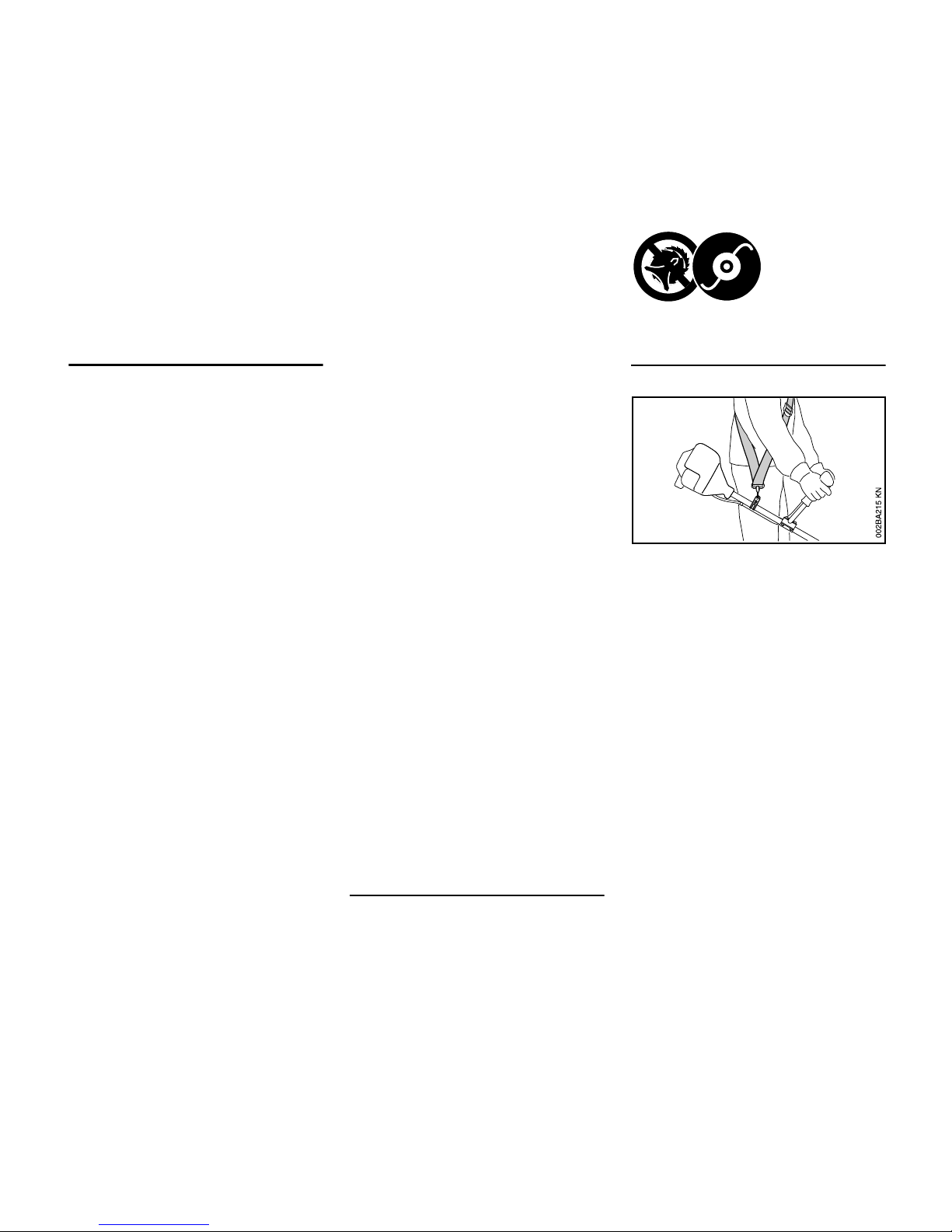
Shoulder strap
N Use a shoulder strap.
N With the engine running, attach the
machine to the shoulder strap.
Grass cutting blades must always be
used in combination with a shoulder
strap.
Use deflector in
combination with
mowing heads
only. Do not use
metal cutting
attachments.
Page 11
FS 55, FS 55 C, FS 55 R, FS 55 RC
English
9
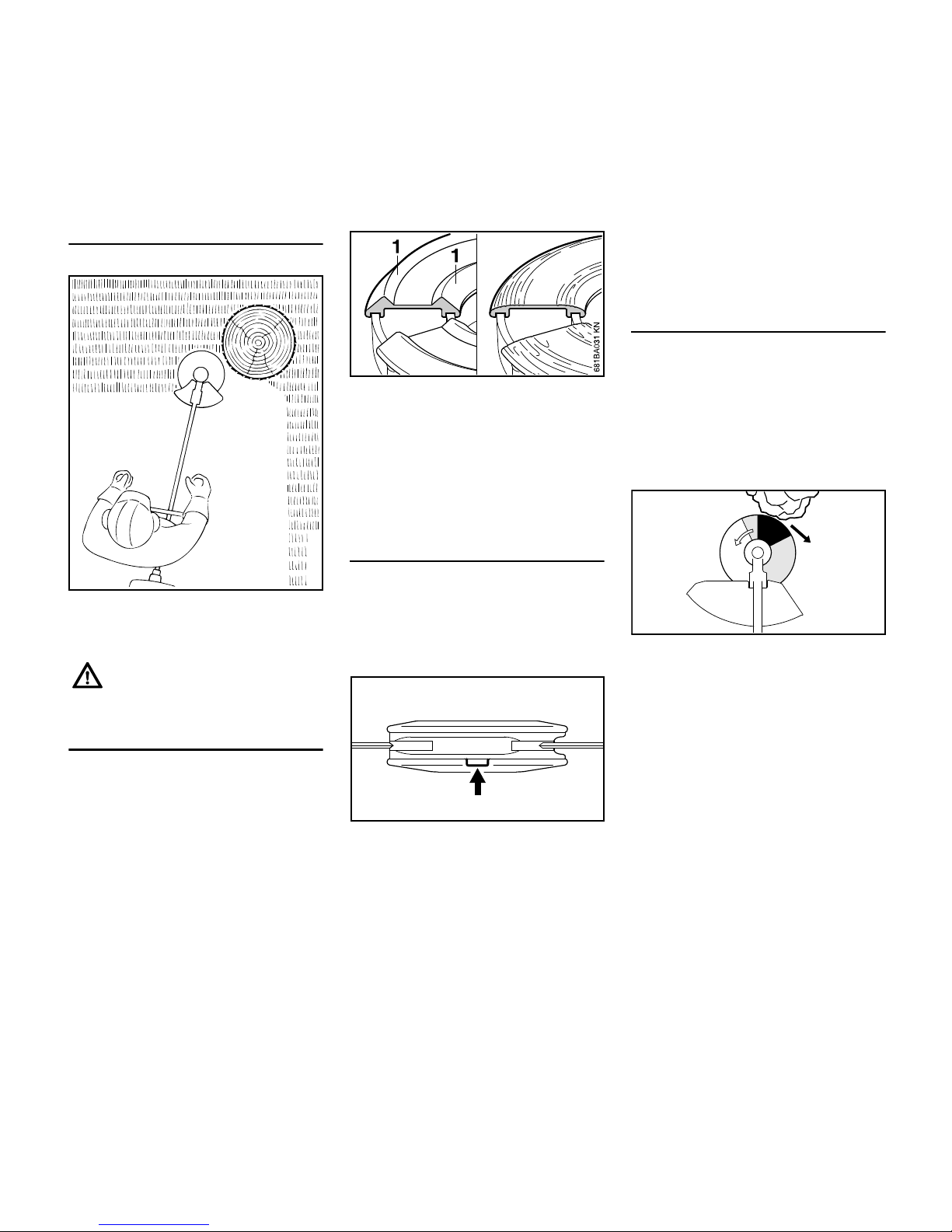
Mowing Head with Nylon Lines
Nylon line achieves a soft cut for edging
and trimming around trees, fence posts,
etc. – less risk of damaging tree bark.
STIHL FixCut
Check the wear limit marks!
N If the raised moldings (1) on the
base of the attachment are worn as
shown in the illustration (above
right), do not continue using the
mowing head. Install a new one.
There is otherwise a risk of injury
from thrown parts of the head.
STIHL Polycut Mowing Head with
Polymer Blades
For mowing unobstructed edges of
meadows (without posts, fences, trees
or similar obstacles).
Check the wear limit marks!
If one of the wear limit marks on the
PolyCut mowing head is worn through
(arrow): Do not continue using the
mowing head. Install a new one. There
is otherwise a risk of injury from thrown
parts of the head.
It is important to follow the maintenance
instructions for the Polycut mowing
head.
Risk of Kickout (Blade Thrust) with
Metal Cutting Blades
When using grass cutting blades there is
a risk of kickout when the rotating blade
comes into contact with a solid object
like a tree trunk, branch, tree stump,
rock or similar. The machine is thrown to
the right or to the rear – opposite to the
blade's direction of rotation.
The risk of kickout is greatest when the
black area of the rotating blade comes
into contact with a solid object.
To reduce the risk of injury,
never use steel wire in place of
the nylon cutting line.
000BA015 KN
002BA177 KN
002BA135 KN
Page 12
FS 55, FS 55 C, FS 55 R, FS 55 RC
English
10
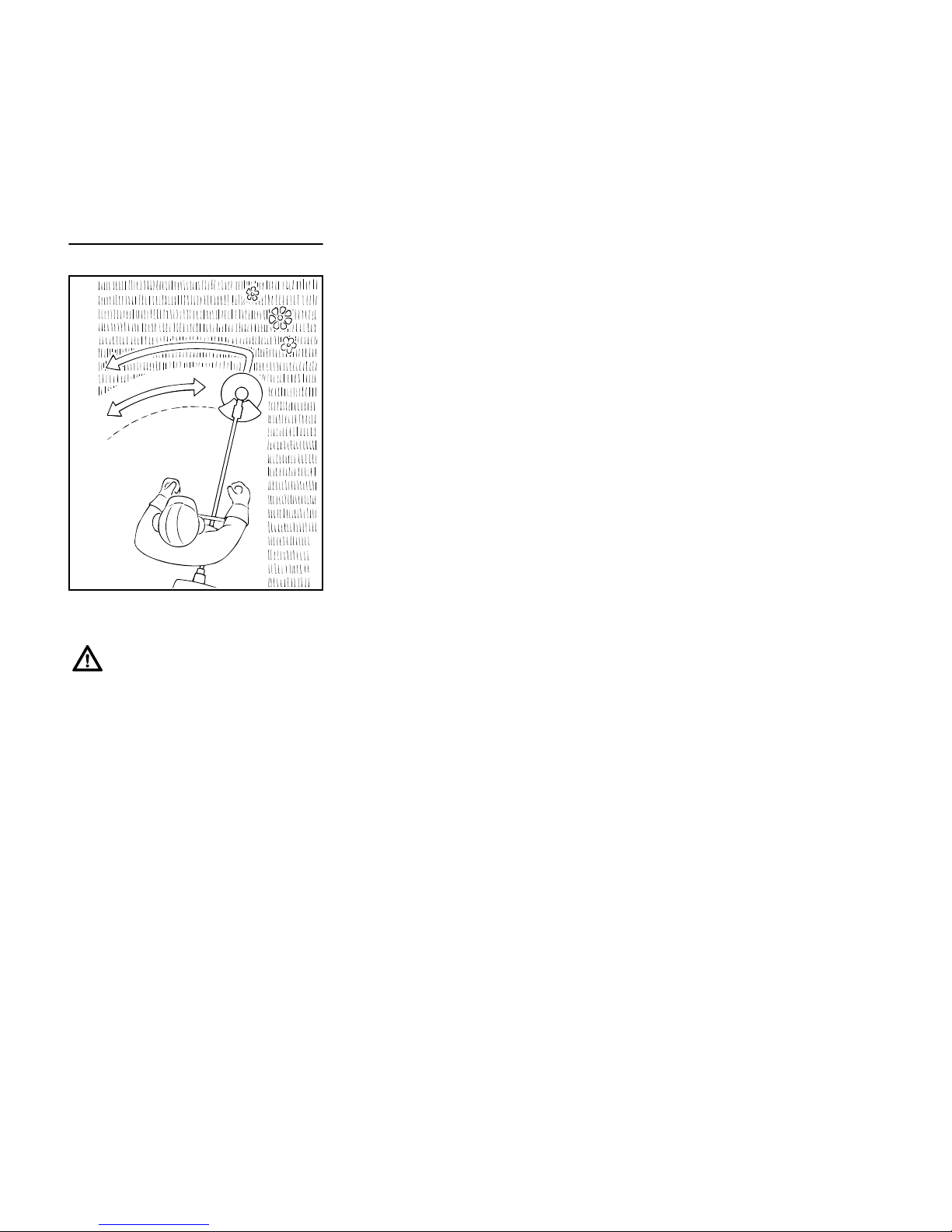
Grass Cutting Blade
Use for grass and weeds only – sweep
the brushcutter in an arc like a scythe.
Resharpen the grass cutting blade
according to instructions when it has
dulled noticeably.
Improper use may damage the
grass cutting blade – risk of
injury from thrown parts.
000BA020 KN
Page 13
FS 55, FS 55 C, FS 55 R, FS 55 RC
English
11
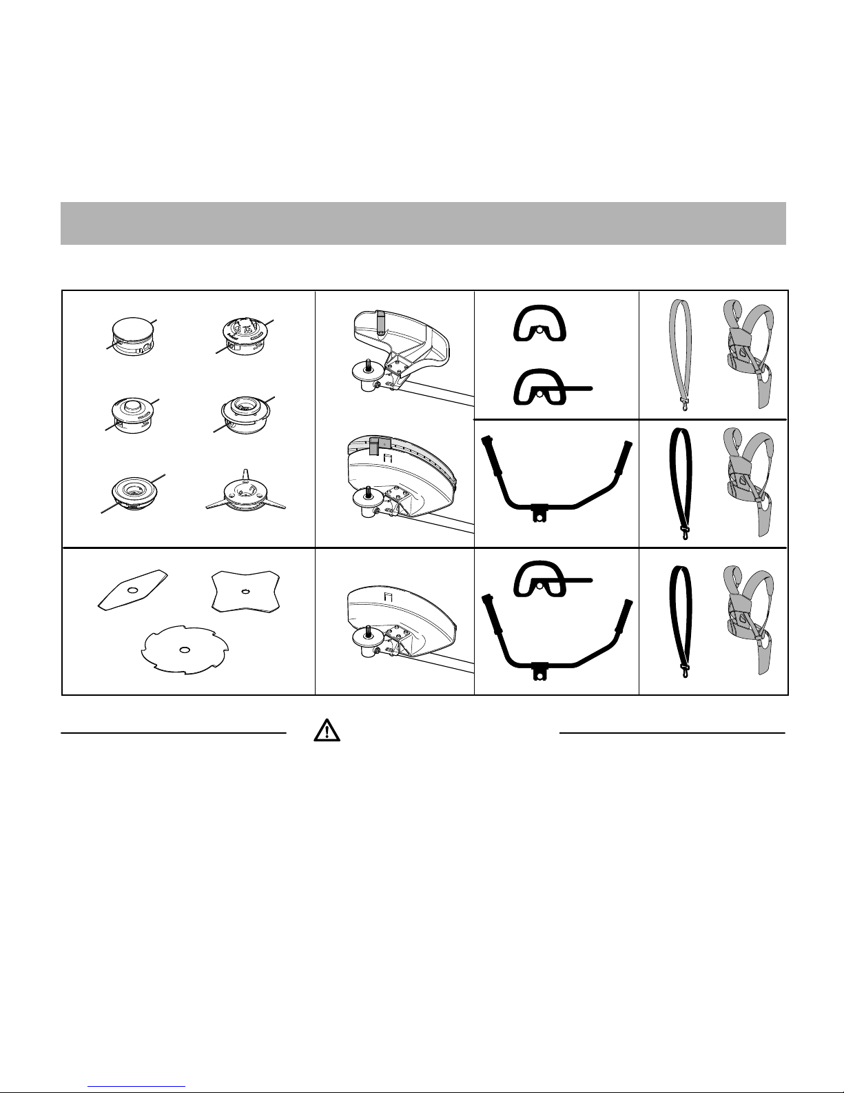
Approved Combinations
Select correct combination from the
table according to the cutting
attachment you intend to use.
Cutting Attachments
Mowing heads
1 STIHL SuperCut 20-2
2 STIHL AutoCut C 25--2
3 STIHL AutoCut 25-2
4 STIHL TrimCut 31-2
5 STIHL FixCut 25-2
Approved Combinations of Cutting Attachment, Deflector, Handle and Harness
Cutting Attachment Deflector Handle Harness / Shoulder
Strap
1
2
3
4
5
6
7
8
9
10
11
12
13
14
15
16
17
15
16
17
19
20
20
19
18
20
681BA120 KN
For safety reasons only the
cutting attachments, deflectors,
handles and harnesses/shoulder
straps shown in each row of the
table may be used together. No
other combinations are permitted
because of the risk of accidents.
Page 14
FS 55, FS 55 C, FS 55 R, FS 55 RC
English
12
6 STIHL PolyCut 20-3
Metal mowing attachments
7 Grass cutting blade 230-2
8 Grass cutting blade 230-4
9 Grass cutting blade 230-8
Deflectors
10 Deflectoronly for mowing heads
11 Deflector with
12 Skirt and blade for all mowing heads
13 Deflector without skirt and blade for
all metal mowing attachments
Handles
14 Loop handle
15 Loop handlewith
16 Barrier bar
17 Bike handle
Harnesses
18 Shoulder strap may be used
19 Shoulder strap must be used
20 Full harness may be used
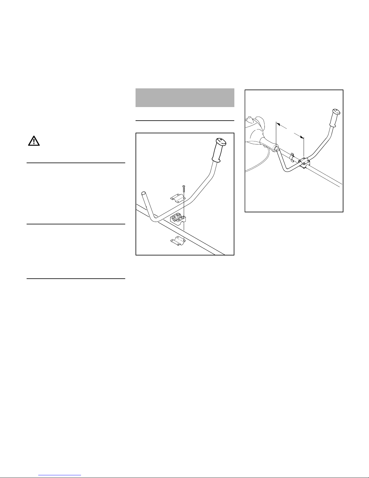
Mounting the handlebar
N Position the clamp (1) and
handlebar support (2) on the
shaft (3)
N Place the handlebar (4) in the
handlebar support – the rubber
handle (5) must be on the left
(viewing direction from engine to
handlebar)
N Place the clamp (6) on the
handlebar support
N Insert screws (7) through the holes
in the parts and screw them into the
clamp (6) as far as they will go
N Fasten handlebar (4) at a
distance (A) of approx. 15 cm (6 in)
ahead of the engine housing on the
shaft (3)
N Align the handlebar and tighten the
screws
Non-metal grass cutting blades
are not approved.
Mounting the Bike Handle
1
3
2
5
7
6
4
233BA025 KN
4
A
3
233BA018 KN
Page 15
FS 55, FS 55 C, FS 55 R, FS 55 RC
English
13
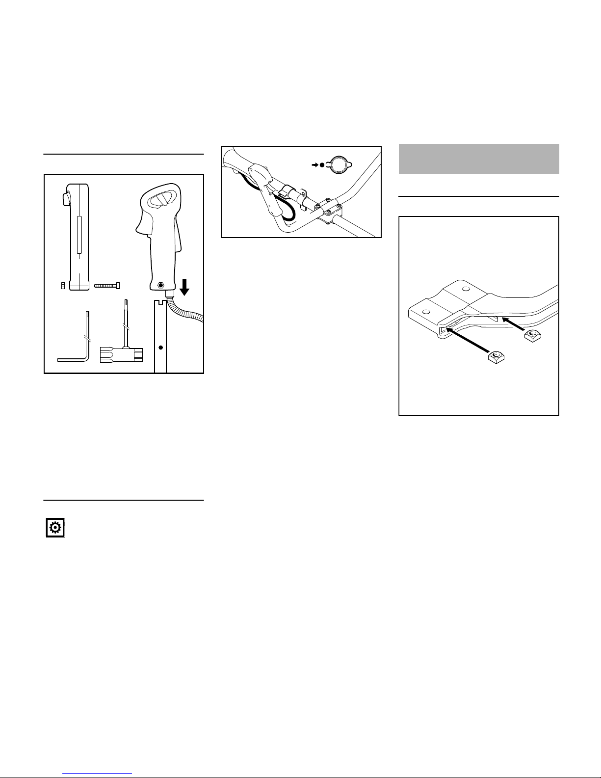
Attaching the control handle
N Unscrew bolt (8) with a combination
wrench or Allen wrench – the nut (9)
remains in the control handle (10)
N Push the control handle with the
throttle trigger (11) facing toward
the gearbox onto the handlebar (4)
until the holes (12) align
N Screw in the bolt (8) and tighten up
Fasten the throttle cable
N Press throttle cable (13) into the
throttle cable support (14)
Loop handle with barrier bar
N Fit the square nuts (1) in the barrier
bar (2); the holes must line up.
Do not kink the throttle cable or
run it in tight radiuses – the
throttle trigger must move freely!
002BA357 KN
12
8
9
4
11
12
10
14
13
14
13
233BA027 KN
Mounting the Loop Handle
2
002BA098 KN
1
1
Page 16
FS 55, FS 55 C, FS 55 R, FS 55 RC
English
14
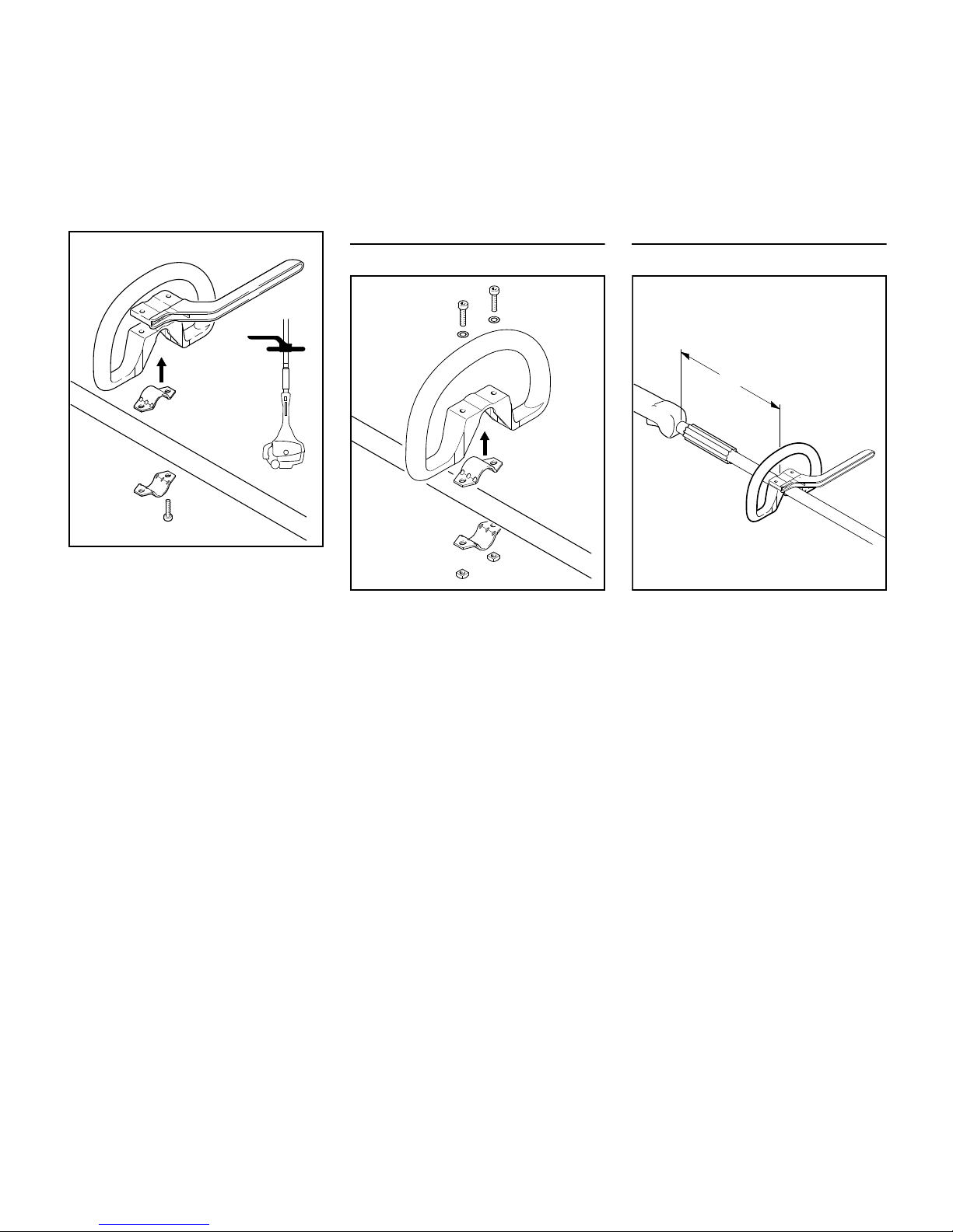
N Fit the clamp (3) in the loop
handle (4) and place them both on
the drive tube (5).
N Place the clamp (6) in position.
N Place the barrier bar (2) in position
as shown.
N Line up the holes.
N Insert the screws (7) and tighten
them down moderately against the
barrier bar.
N Go to "Securing the loop handle".
Loop handle without barrier bar
N Fit the clamp (3) in the loop
handle (4) and place them both on
the drive tube (5).
N Place the clamp (6) in position.
N Line up the holes.
N Fit washers (7) on the screws (8)
and insert the screws in the holes.
Fit the square nuts (1) and screw
them down as far as stop.
N Go to "Securing the loop handle".
Securing the loop handle
N Secure the loop handle (4) about
20cm/8in (A) forward of the control
handle (9).
N Line up the loop handle.
N Tighten down the screws firmly –
lock the nuts if necessary.
The sleeve (10) (not fitted on all models)
must be between the loop handle and
the control handle.
5
4
002BA099 KN
2
3
6
7
4
5
002BA136 KN
1
6
1
3
8
7
8
7
10
9
4
002BA147 KN
A
Page 17
FS 55, FS 55 C, FS 55 R, FS 55 RC
English
15
The carrying ring comes standard with
the machine or is available as a special
accessory.
For position of carrying ring see "Main
Parts".
N Place the clamp (1) against the
drive tube with the tapped hole on
the left (viewed from engine).
N Squeeze the two ends of the clamp
together and hold in that position.
N Insert the M6x14 screw (2).
N Line up the carrying ring.
N Tighten down the screw firmly.
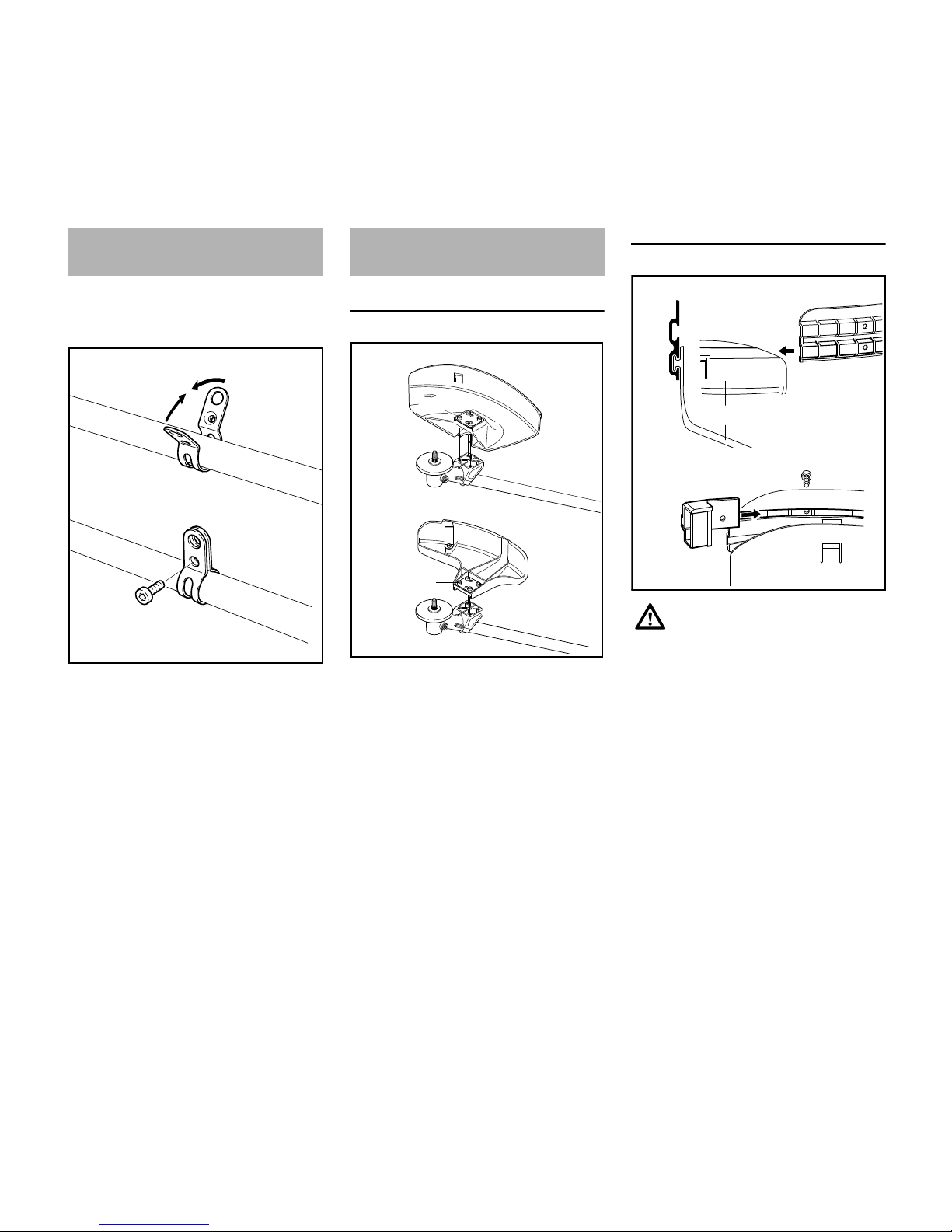
Mounting the Deflector
1 Deflector for mowing attachments
2 Deflector for mowing heads
Deflectors (1) and (2) are both mounted
to the gearbox in the same way.
N Place the deflector on the gearbox
flange.
N Insert the screws (3) and tighten
them down firmly.
Fitting the Skirt and Blade
N Slide the lower guide slot of the skirt
(4) onto the deflector (1) – it must
snap into position.
N Push the blade (5) into the upper
guide slot on the skirt and line it up
with the first hole.
N Insert the screw and tighten it down
firmly.
Fitting the Carrying Ring
002BA142 KN
1
2
1
Mounting the Deflector
002BA380 KN
2
1
3
3
These parts must be fitted to the
deflector (1) when you use a
mowing head.
4
1
5
4
002BA103 KN
Page 18
FS 55, FS 55 C, FS 55 R, FS 55 RC
English
16
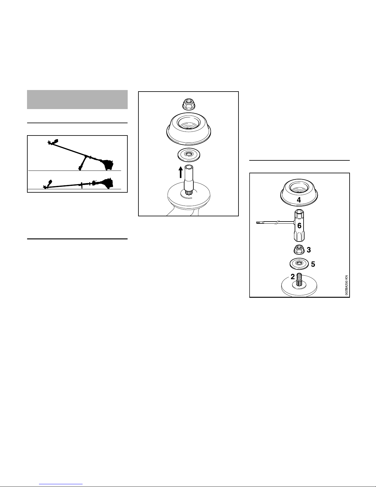
Preparations
N Lay your brushcutter on its back so
that the cutting attachment
mounting face is facing up.
Mounting hardware for cutting
attachments
The mounting hardware supplied
depends on the cutting attachment that
comes as original equipment with the
new machine.
Mounting hardware is not packed
with machine
Only mowing heads can be mounted.
N Pull the hose (1) (protector for
shipping) off the shaft (2).
N Go to "Mounting the mowing head".
If you want to mount a metal cutting
attachment in place of a mowing head,
you will need the following additional
parts: Nut (3), rider plate (4) and thrust
washer (5) (special accessories).
Mounting hardware is packed with
machine
Mowing heads and metal cutting
attachments may be mounted.
If the parts are packed with the
machine
N Pull the hose (1) (protector for
shipping) off the shaft (2).
The nut (3), rider plate (4) and thrust
wsher (5) are in the parts kit supplied
with the machine.
N Go to "Mounting the mowing head"
or "Mounting the metal cutting
attachment".
If the parts are mounted to the
gearbox
N Go to "Removing the mounting
hardware".
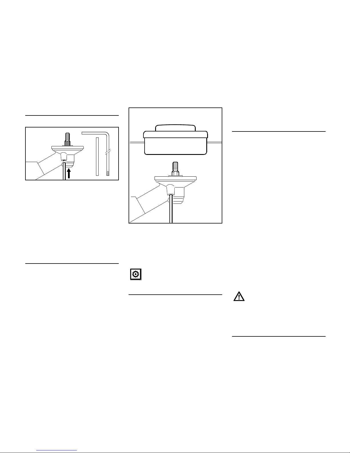
Removing the mounting hardware
N Block the shaft – see next chapter
on "Blocking the output shaft".
N Use the combination wrench (6) –
comes standard with machine or is
available as special accessory – to
unscrew the nut (3) clockwise (lefthand thread) from the shaft (2).
N Pull the thrust washer (5) off the
shaft (2).
The rider plate (4) is in the parts kit
supplied with the machine.
Mounting the Cutting
Attachment
002BA104 KN
2
002BA164 KN
1
3
4
5
Page 19
FS 55, FS 55 C, FS 55 R, FS 55 RC
English
17
N Go to "Mounting the mowing head"
or "Mounting the metal cutting
attachment".
Blocking the output shaft
N Insert the stop pin (7) or screwdriver
– come standard with machine or
are available as special accessories
– in the hole (8) in the gearbox as
far as stop, and apply slight
pressure.
N Rotate the nut or cutting attachment
on the shaft (2) until the stop pin
slips into position and blocks the
shaft.
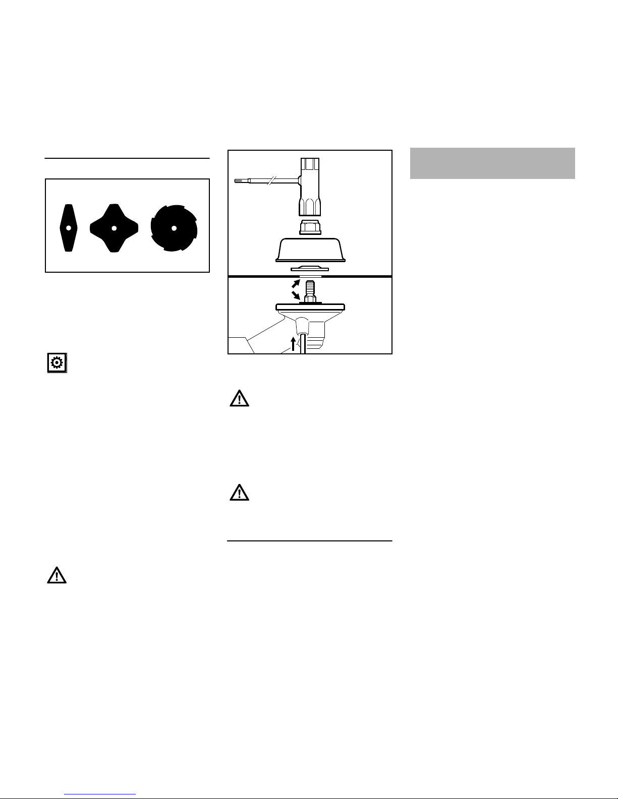
Mounting the Mowing Head
Keep the instruction sheet for the
mowing head in a safe place.
STIHL SuperCut 20-2,
STIHL AutoCut 25-2,
STIHL AutoCut C 25-2,
STIHL TrimCut 31-2,
STIHL FixCut 25-2,
STIHL PolyCut 20-3
N Screw the mowing head
counterclockwise on to the shaft (1)
as far as stop.
N Block the shaft.
N Tighten down the mowing head.
Removing the Mowing Head
N Block the shaft.
STIHL SuperCut 20-2,
STIHL AutoCut 25-2,
STIHL AutoCut C 25-2,
STIHL TrimCut 31-2,
STIHL FixCut 25-2,
STIHL PolyCut 20-3
N Unscrew the mowing head
clockwise.
Adjusting Nylon Line
STIHL SuperCut
Fresh line is advanced automatically if
remaining line is still at least 6cm long.
The blade on the deflector trims surplus
line to the correct length.
STIHL AutoCut
N Hold the rotating mowing head
above the ground – tap it on the
ground once – about 3cm fresh line
is advanced.
The blade on the deflector trims surplus
line to the correct length – avoid tapping
the mowing head more than once at a
time.
Line feed operates only if both lines still
have a minimum length of 2.5 cm.
All other mowing heads
Refer to the instructions supplied with
the mowing head.
Replacing Nylon Line or Cutting
Blades
Refer to the instructions supplied with
the mowing head.
7
8
2
002BA166 KN
7
Remove the tool used to block the
shaft.
1
002BA081 KN
To reduce the risk of injury, always
shut off the engine before
adjusting the mowing line by
hand.
Page 20
FS 55, FS 55 C, FS 55 R, FS 55 RC
English
18
Fitting metal cutting attachments
For the grass cutting blades 230-2 (1),
230-4 (2) and 230-8 (3) the attached
parts skirt and blade are not
necessary are not necessary on the
mowing tool deflector – see "Mounting
the deflector".
If the machine is supplied already
equipped with a metal cutting
attachment, then the correct thrust
plate (5, next fig.) is already mounted.
N Lay down the trimmer with the
mount for the cutting attachment
facing upward
With the grass cutting blades (1) and (2),
the cutting edges may face in either
direction.
With grass cutting blade (3), the cutting
edges must face clockwise.
N Position the blade (4) on the thrust
plate (5).
N Push the thrust plate (6) and rider
plate (7) onto the shaft (8)
N Block the shaft and screw the
nut (9) counterclockwise onto the
shaft and tighten it
Removing the metal cutting
attachment
N Block the shaft
N Unscrew the nut clockwise
N Remove parts from the shaft – do
not remove the thrust plate (5) in
doing so
This engine is certified to operate on
unleaded gasoline and with the mix ratio
50:1.
Your engine requires a mixture of highquality premium gasoline and highquality two-stroke air-cooled engine oil.
Use premium branded unleaded
gasoline with a minimum octane rating
of 89 RON.
Note: Models equipped with a catalytic
converter require unleaded gasoline. A
few tankfuls of leaded gasoline can
reduce the efficiency of the catalytic
converter by more than 50%.
Fuel with a lower octane rating may
result in preignition (causing "pinging")
which is accompanied by an increase in
engine temperature. This, in turn,
increases the risk of the piston seizure
and damage to the engine.
The chemical composition of the fuel is
also important. Some fuel additives not
only detrimentally affect elastomers
(carburetor diaphragms, oil seals, fuel
lines etc.), but magnesium castings as
well. This could cause running problems
or even damage the engine. For this
reason it is essential that you use only
high-quality fuels!
Fuels with different percentages of
ethanol are being offered. Ethanol can
affect the running behaviour of the
engine and increase the risk of lean
seizure.
For metal cutting attachments,
use a special version of the thrust
plate (5, next fig.) – to this end, if
necessary, have the machine
checked by a servicing dealer.
Observe the arrow for the
direction of rotation on the inside
of the mowing tool deflector.
1
2
3
681BA121 KN
The collar (arrow) must engage
the hole in the blade.
A nut that moves too easily should
be replaced.
681BA051 KN
6
9
7
8
5
4
Fuel
Page 21
FS 55, FS 55 C, FS 55 R, FS 55 RC
English
19
Gasoline with an ethanol content of
more than 10% can cause running
problems and major damage in engines
with a manually adjustable carburetor
and should not be used in such engines.
Engines equipped with M-Tronic can be
run on gasoline with an ethanol content
of up to 25% (E25).
Use only STIHL two-stroke engine oil or
equivalent high-quality two-stroke aircooled engine oils for mixing.
We recommend STIHL 50:1 two-stroke
engine oil since it is specially formulated
for use in STIHL engines.
Do not use BIA or TCW (two-stroke
water cooled) mix oils!
Use only STIHL 50:1 heavy-duty
engine oil or an equivalent quality twostroke engine oil for the fuel mix in
models equipped with a catalytic
converter.
Take care when handling gasoline.
Avoid direct contact with the skin and
avoid inhaling fuel vapour.
The canister should be kept tightly
closed in order to avoid any moisture
getting into the mixture.
The fuel tank and the canister in which
fuel mix is stored should be cleaned
from time to time.
Fuel mix ratio
Only mix sufficient fuel for a few days
work, not to exceed 3 months of storage.
Store in approved safety fuel-canisters
only. When mixing, pour oil into the
canister first, and then add gasoline.
Dispose of empty mixing-oil canisters
only at authorized disposal locations.
N Before fueling, clean the filler cap
and the area around it to ensure that
no dirt falls into the tank.
N Position the machine so that the
filler cap is facing up.
N Open the filler cap.
Take care not to spill fuel while fueling
and do not overfill the tank. STIHL
recommends you use the STIHL filler
nozzle (special accessory).
Examples
Gasoline Oil (STIHL 50:1 or equiva-
lent high-quality oils)
liters liters (ml)
10.02(20)
5 0.10 (100)
10 0.20 (200)
15 0.30 (300)
20 0.40 (400)
25 0.50 (500)
Fueling
After fueling, tighten down the
filler cap as securely as possible
by hand.
232BA046 KN
Page 22
FS 55, FS 55 C, FS 55 R, FS 55 RC
English
20
The type and style of the harness
depend on the market.
The use of the shoulder strap is
described in the chapter on "Approved
Combinations of Cutting Attachment,
Deflector, Handle and Harness".
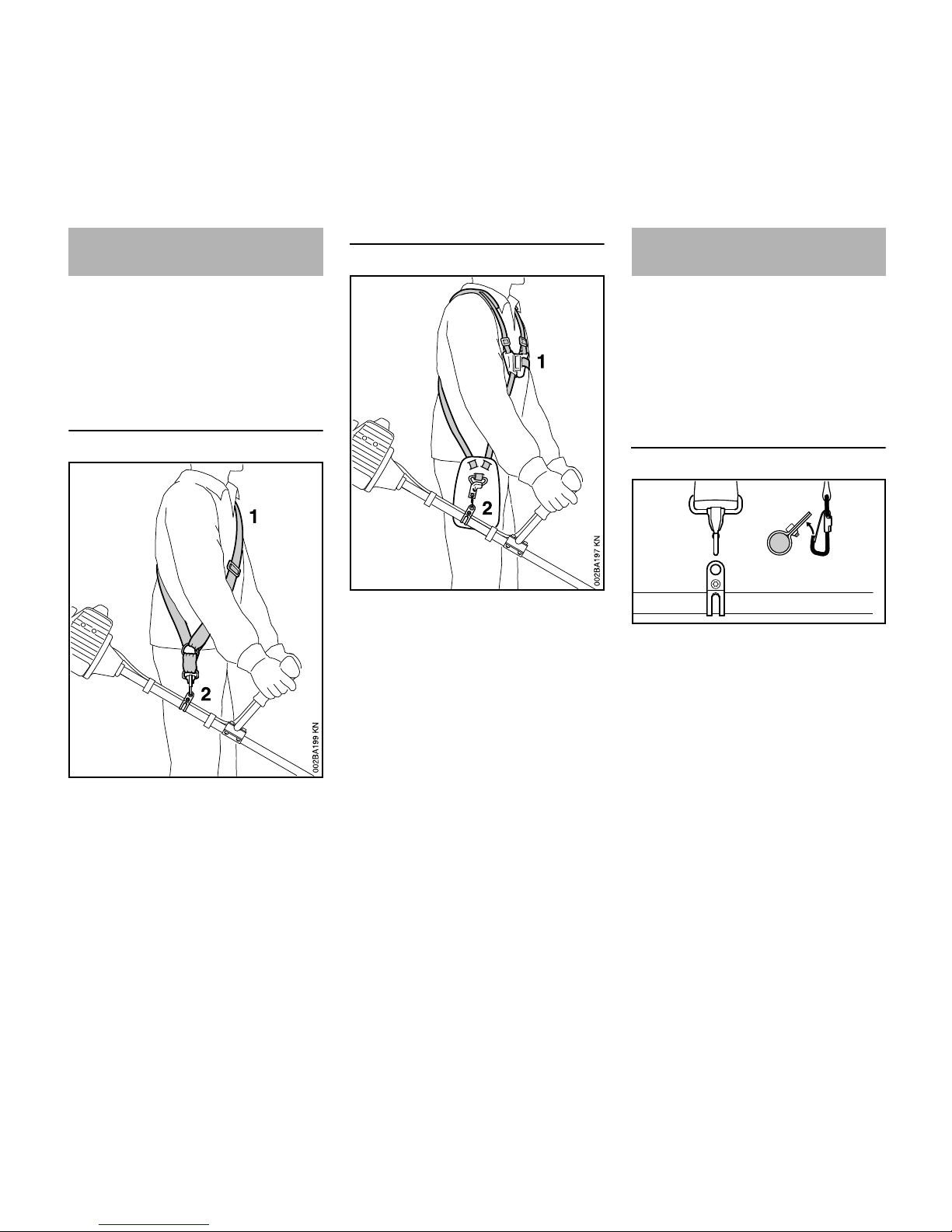
Shoulder strap
N Put on the shoulder strap (1).
N Adjust the length of the strap so that
the spring hook (2) is about a hand’s
width below your right hip.
N Balance the trimmer/brushcutter.
Full harness
N Put on the full harness (1).
N Adjust the length of the strap so that
the spring hook (2) is about a hand’s
width below your right hip.
N Balance the trimmer/brushcutter.
The type and style of the harness and
carabiner (spring hook) depend on the
market.
The carrying ring is integrated in the
control handle on loop-handled units–
see "Main Parts". Loop-handled units do
not need to be balanced.
Attaching the unit to the harness
N Attach the carabiner (1) to the
carrying ring (2) on the drive tube.
Fitting the Harness Balancing the
Trimmer/Brushcutter
1
2
1
2
002BA311 KN
Page 23
FS 55, FS 55 C, FS 55 R, FS 55 RC
English
21
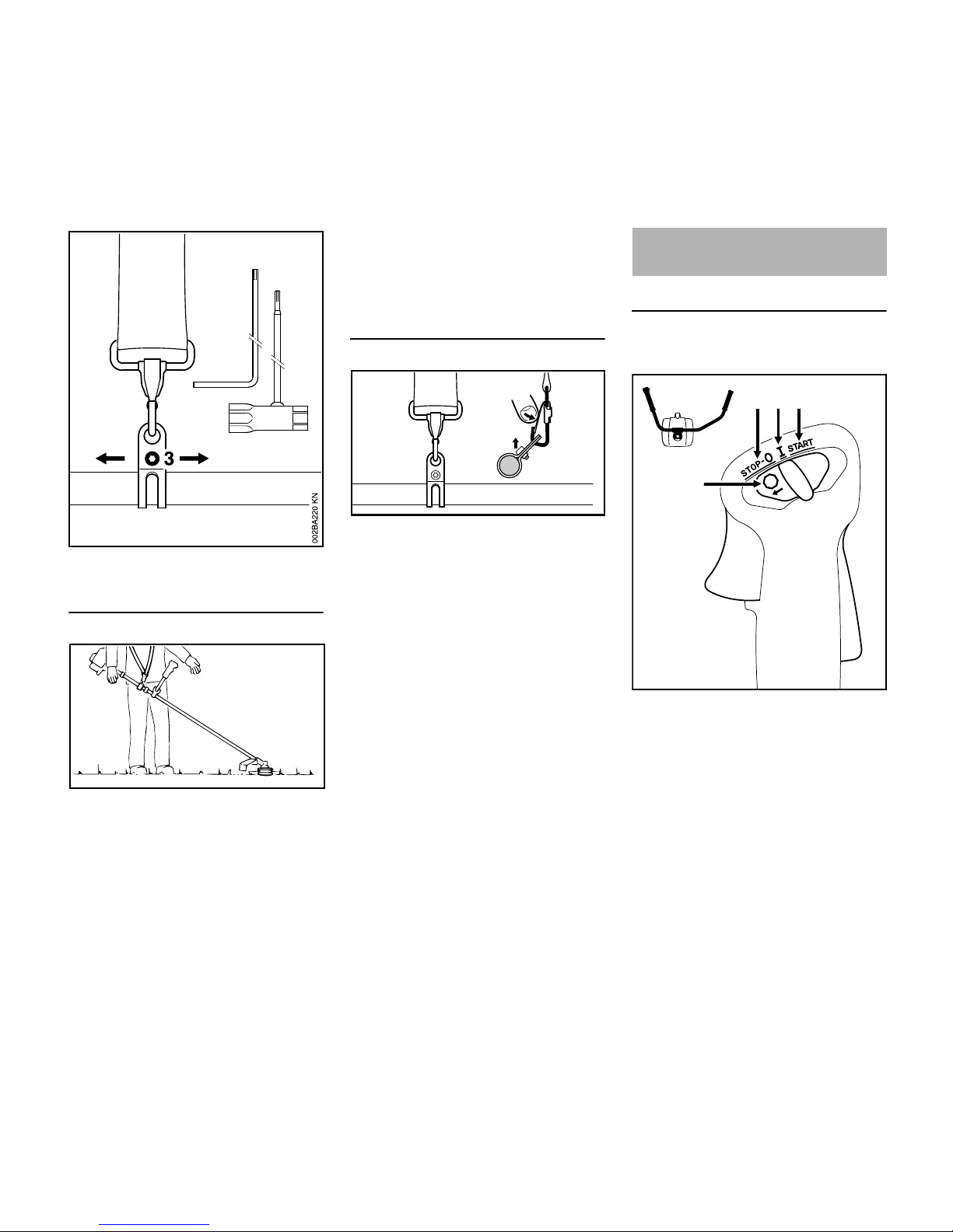
N Loosen the screw (3).
Floating position
N Mowing heads and grass cutting
blades should just touch the ground.
Proceed as follows to adjust the floating
position:
N Move the carrying ring up or down
the drive tube – tighten the screw
moderately – let the unit go and wait
until is its balanced – then check the
floating position.
When the correct floating position has
been reached:
N Tighten down the screw on the
carrying ring firmly.
Detaching the unit from the harness
N Press down the bar on the
carabiner (1) and pull the carrying
ring (2) out of the carabiner.
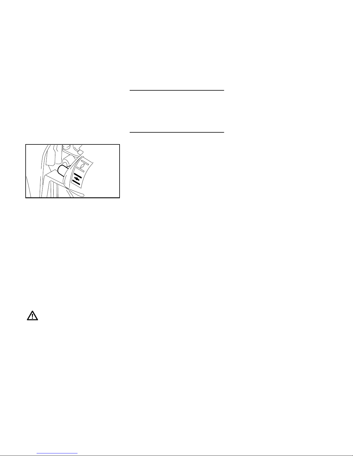
Version with bike handle
Controls
1 Throttle trigger lockout
2 Throttle trigger
3 Slide control
Positions of slide control
4 START – the ignition is switched on
– the engine can start
5 F – normal run position – the engine
is running or can start
6STOP-0 – engine off – the ignition is
switched off
002BA313 KN
1
2
1
2
002BA312 KN
Starting / Stopping the
Engine
1
4
56
7
3
2
STOP
233BA037 KN
Page 24
FS 55, FS 55 C, FS 55 R, FS 55 RC
English
22
Symbol on slide control
7 h – stop symbol and arrow. To stop
the engine, push the slide control in
the direction of the arrow on the stop
symbol (h) to STOP-0.
Starting
N Press down the trigger lockout lever
and squeeze the throttle trigger.
N and hold them in that position.
N Move the slide control to START
and hold it there.
N Now release the throttle trigger,
slide control and trigger lockout in
that order. This is the starting
throttle position.
N Go to "All versions".
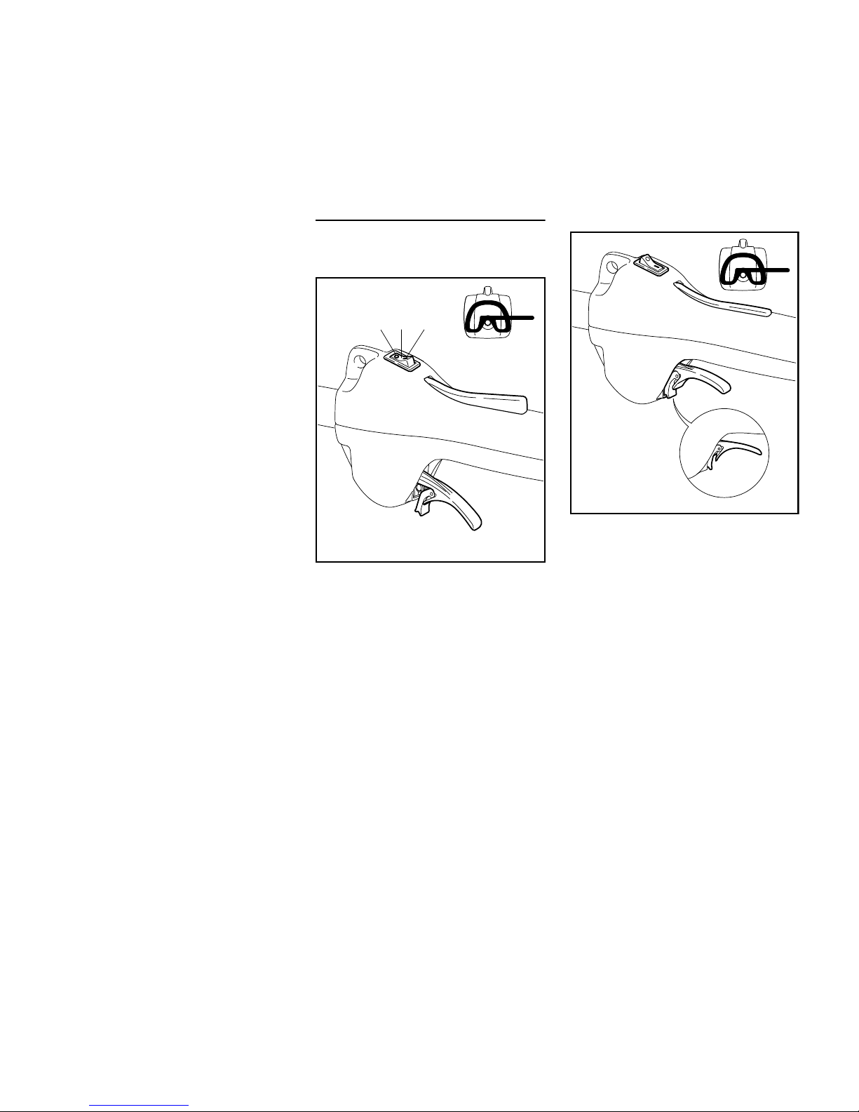
Version with loop handle
Controls
1 Stop switch
2 Throttle trigger lockout
3 Throttle trigger
4 Tongue of throttle trigger
5 Catch
Positions of stop switch
6I – normal run position – the engine
can start or is running
70 – Stop – engine off – the ignition is
switched off
Starting
N Move the stop switch to I.
N Press down the throttle trigger
lockout and hold it there.
N Squeeze the throttle trigger until the
catch on the tongue (4) can be
engaged on the housing.
N Now release the throttle trigger,
tongue and trigger lockout in that
order. This is the starting throttle
position.
N Go to "All versions".
2
233BA048 KN
1
6
7
5
4
3
233BA049 KN
4
Page 25
FS 55, FS 55 C, FS 55 R, FS 55 RC
English
23
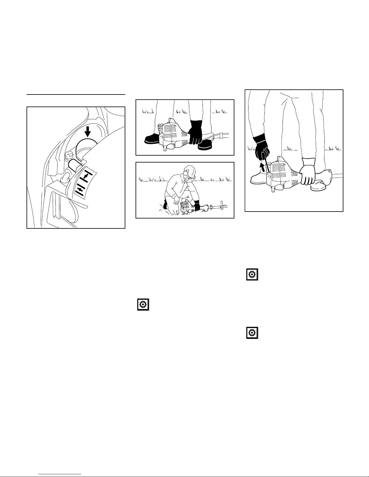
All versions
N Set the choke lever (8) to
N Press the fuel pump bulb (9) at least
five times – even if the bulb is
already filled with fuel.
Starting
N Place the unit on the ground: It must
rest securely on the engine support
and the deflector. Check that the
cutting attachment is not touching
the ground or any other obstacles.
N Make sure you have a safe and
secure footing.
N Hold the unit with your left hand and
press it down firmly – your thumb
should be under the fan housing.
N Hold the starter grip with your right
hand.
Version without Easy2Start
N Pull the starter grip slowly until you
feel it engage and then give it a brisk
strong pull.
Version with Easy2Start
N Pull the starter grip slowly until you
feel it engage and then pull it out
slowly and steadily.
g if the engine is cold
e for warm start – also use this posi-
tion if the engine has been running
but is still cold.
9
8
232BA011 KN
Do not stand or kneel on the drive
tube.
233BA020 KN
233BA014 KN
Do not pull out the starter rope all
the way – it might otherwise
break.
Do not pull out the starter rope all
the way – it might otherwise
break.
232BA014 KN
Page 26
FS 55, FS 55 C, FS 55 R, FS 55 RC
English
24
Both versions
N Do not let the starter grip snap back.
Guide it slowly back into the housing
so that the starter rope can rewind
properly.
N Continue cranking.
When the engine begins to fire:
N After no more than five pulls, move
the choke lever (8) to e.
N Continue cranking.
As soon as the engine runs
Version with bike handle
N Blip the throttle trigger – the engine
settles down to idle speed.
Version with loop handle
N Squeeze the throttle trigger to
disengage the tongue – the engine
will settle down to idle speed.
Your machine is now ready for
operation.
Stopping the engine
N Move the slide control in direction of
the arrow (h) to STOP-0 or the stop
switch to STOP / 0.
If the engine does not start
Choke lever
If you did not move the choke lever to e
quickly enough after the engine began to
fire, the combustion chamber is flooded.
N Set the choke lever to
e .
N Set the slide control, trigger lockout
lever and throttle trigger to the
starting throttle position.
N Start the engine by pulling the
starter rope briskly – 10 to 20 pulls
may be necessary.
If the engine still does not start
N Move the slide control or stop switch
to STOP / 0.
N Remove the spark plug – see
"Spark Plug".
N Dry the spark plug.
N Crank the engine several times with
the starter to clear the combustion
chamber.
N Refit the spark plug – see "Spark
Plug".
N Move the slide control or stop switch
to F / I.
N Set the choke lever to e – even if
the engine is cold.
N Now start the engine.
Fuel tank run until completely dry
N After refueling, press the fuel pump
bulb at least five times – even if the
bulb is filled with fuel.
N Set the choke lever to suit the
engine temperature.
N Start the engine.
Make sure the carburetor is
correctly adjusted. The cutting
attachment must not rotate when
the engine is idling.
8
232TI015 KN
Page 27

FS 55, FS 55 C, FS 55 R, FS 55 RC
English
25
During break-in period
A factory-new machine should not be
run at high revs (full throttle off load) for
the first three tank fillings. This avoids
unnecessary high loads during the
break-in period. As all moving parts
have to bed in during the break-in
period, the frictional resistances in the
engine are greater during this period.
The engine develops its maximum
power after about 5 to 15 tank fillings.
During Operation
After a long period of full throttle
operation, allow the engine to run for a
short while at idle speed so that engine
heat can be dissipated by the flow of
cooling air. This protects enginemounted components (ignition,
carburetor) from thermal overload.
After Finishing Work
Storing for a short period: Wait for the
engine to cool down. Empty the fuel tank
and keep the machine in a dry place,
well away from sources of ignition, until
you need it again. For longer out-ofservice perionds – see "Storing the
Machine".
If there is a noticeable loss of engine
power
N Set the choke lever to g.
N Press in the tab (1) and swing the
filter cover (2) down.
N Clean away loose dirt from around
the filter.
N Remove the felt element (3) from
the filter housing (4) and replace it –
knock out or blow out as a
temporary measure – do not wash.
N Replace damaged parts.
N Fit the felt element (3) in the filter
housing (4).
N Close the filter cover so that it snaps
into position.
Operating Instructions Cleaning the Air Filter
232BA017 KN
1
2
232BA018 KN
4
3
Page 28

FS 55, FS 55 C, FS 55 R, FS 55 RC
English
26
Exhaust emissions are controlled by the
design of the fundamental engine
parameters and components (e.g.
carburation, ignition, timing and valve or
port timing) without the addition of any
major hardware.
The carburetor comes from the factory
with a standard setting.
This setting provides an optimum fuel-air
mixture under most operating
conditions.
With this carburetor it is only possible to
adjust the high speed screw within fine
limits.
Standard Setting
N Stopping the Engine
N Mounting the cutting attachment
N Check the air filter and replace it if
necessary.
N Have the spark arrestor checked –
see “Inspection and Maintenance
by Dealer"
N Turn high speed screw (H)
counterclockwise as far as stop (no
more than 3/4 turn).
N Turn the low speed screw (L)
carefully clockwise as far as stop,
then turn it back 1.5 turns.
N Start and warm up the engine if
necessary.
N Adjust idle speed with the idle speed
screw (LA) so that the cutting
attachment does not rotate.
Fine Tuning
A slight correction of the setting of the
high speed screw (H) may be necessary
if engine power is not satisfactory when
operating at high altitude, sea level or
after changing the cutting attachment.
Engine Management Adjusting the Carburetor
L
H
LA
233BA050 KN
Page 29

FS 55, FS 55 C, FS 55 R, FS 55 RC
English
27
Rule of thumb:
Turn the high speed screw (H) about
one quarter of a turn for every 1000 m
(3300 ft) change in altitude.
Conditions for adjustment
N Carry out the standard setting.
N Start the engine and, with the
mowing head mounted, warm it up
for about 3 minutes.
N Open the throttle wide.
At high altitude
N Turn the high speed screw (H)
clockwise (leaner), no further than
stop, until there is no further
noticeable increase in engine
speed.
At sea level
N Turn the high speed screw (H)
counterclockwise (richer), no further
than stop, until there is no further
noticeable increase in engine
speed.
It is possible that maximum engine
speed may be reached with the standard
setting in each case.
Aadjusting Idle Speed
It is usually necessary to change the
setting of the idle speed screw (LA) after
every correction to the low speed
screw (L).
N Warm up the engine.
Engine stops while idling
N Turn the idle speed screw (LA)
slowly clockwise until the engine
runs smoothly – the cutting
attachment must not turn.
Cutting attachment rotates when
engine is idling
N Turn the idle speed screw (LA)
counterclockwise until the cutting
attachment stops moving and then
rotate the screw another 1/2 to 1
turn in the same direction.
Erratic idling behavior, engine stops
even though setting of LA-screw has
been corrected, poor acceleration
Idle setting is too lean:
N Idle setting is too lean: Rotate the
low speed screw (L) about 1/4 turn
counterclockwise until the engine
runs and accelerates smoothly.
Erratic idling behavior
Idle setting is too rich
N Rotate the low speed screw (L)
about 1/4 turn clockwise until the
engine runs and accelerates
smoothly.
Adjust the high speed screw (H)
only if you are using a mowing
head, making sure the cutting
lines are full length (as far as the
line limiter blade on the deflector).
If a metal cutting attachment is
mounted, use the standard setting
and adjust the high speed
screw (H) as described above
under "Rule of thumb".
If the cutting attachment continues
to run when the engine is idling,
have your machine checked and
repaired by your servicing dealer.
Page 30

FS 55, FS 55 C, FS 55 R, FS 55 RC
English
28
N If the engine is down on power,
difficult to start or runs poorly at idle
speed, first check the spark plug.
N Fit a new spark plug after about 100
operating hours – or sooner if the
electrodes are badly eroded. Install
only suppressed spark plugs of the
type approved by STIHL – see
"Specifications".
Removing the Spark Plug
N Move the stop switch to 0.
N Pull off the spark plug boot (1).
N Unscrew the spark plug.
Checking the spark plug
N Clean dirty spark plug.
N Check electrode gap (A) and
readjust if necessary – see
"Specifications".
N Rectify the problems which have
caused fouling of the spark plug.
Possible causes are:
– Too much oil in fuel mix.
– Dirty air filter.
– Unfavorable running conditions.
Installing the spark plug
N Screw home the spark plug, fit the
boot and press it down firmly.
Spark Plug
1
232BA081 KN
If the spark plug comes with a
detachable adapter nut (1), screw
the adapter onto the thread and
tighten it down firmly to reduce
the risk of arcing and fire.
000BA039 KN
A
1
000BA045 KN
Page 31

FS 55, FS 55 C, FS 55 R, FS 55 RC
English
29
If engine running behavior is
unsatisfactory even though the air filter
is clean and the carburetor is properly
adjusted, the cause may be the muffler.
Have the muffler checked for
contamination (carbonization) by your
servicing dealer.
STIHL recommends that you have
servicing and repair work carried out
exclusively by an authorized STIHL
servicing dealer.
To help prolong the wear life of the
starter rope, observe the following
points:
N Pull the starter rope only in the
direction specified.
N Do not pull the rope over the edge of
the guide bushing.
N Do not pull out the rope more than
specified.
N Do not allow the starter grip to snap
back, guide it back into the housing
slowly – see chapter on "Starting /
Stopping the Engine."
Have a damaged starter rope replaced
by your dealer before it breaks
completely. STIHL recommends that
you have servicing and repair work
carried out exclusively by an authorized
STIHL servicing dealer.
For periods of 3 months or longer
N Drain and clean the fuel tank in a
well ventilated area.
N Dispose of fuel properly in
accordance with local
environmental requirements.
N Run the engine until the carburetor
is dry – this helps prevent the
carburetor diaphragms sticking
together.
N Remove, clean and inspect the
cutting attachment.
N Thoroughly clean the machine –
pay special attention to the cylinder
fins and air filter.
N Store the machine in a dry and
secure location – out of the reach of
children and other unauthorized
persons.
Engine Running Behavior Rewind Starter Storing the Machine
Page 32

FS 55, FS 55 C, FS 55 R, FS 55 RC
English
30
N Use a sharpening file (see "Special
Accessories") to sharpen dull
cutting attachments. In case of
more serious wear or nicks:
Resharpen with a grinder or have
the work done by a dealer – STIHL
recommends a STIHL servicing
dealer.
N Resharpen frequently, take away as
little material as possible: two or
three strokes of the file are usually
enough.
N Resharpen the cutters (1) uniformly
– do not alter the contour or the
parent blade (2) in any way.
See cutting attachment packaging for
additional sharpening instructions.
Balancing
N After resharpening about 5 times,
check the cutting attachment for
out-of-balance on a STIHL balancer
– see “Special Accessories” – or
have it checked by a dealer and rebalanced as necessary – STIHL
recommends a STIHL servicing
dealer.
Maintenance Work
STIHL recommends that you have
servicing and repair work carried out
exclusively by an authorized STIHL
servicing dealer.
Fuel Pickup Body in Tank
N Have the pickup body in the fuel
tank replaced every year.
Spark Arrestor in Muffler
N If the engine is down on power,
have the spark arrestor in the
muffler checked. The spark arrestor
is not installed in all markets
Lubricating the Gearbox
N Have the grease level in the
gearbox checked regularly – about
every 25 hours of operation.
Sharpening Metal Cutting
Blades
2
2
1
002BA113 KN
2
1
1
Inspections and
Maintenance by Dealer
Page 33

FS 55, FS 55 C, FS 55 R, FS 55 RC
English
31
Maintenance and Care
The following intervals apply to normal operating conditions only. If your daily working time is longer or operating conditions are difficult (very dusty work area, etc.),
shorten the specified intervals accordingly.
before starting work
after finishing work or daily
after each refueling stop
weekly
monthly
every 12 months
if problem
if damaged
if required
Complete machine
Visual inspection (condition, leaks) XX
Clean X
Control handle Check operation XX
Air filter
Clean XX
Replace X
Pickup body in fuel tank
Check X
Have replaced by dealer
1)
XXX
Fuel tank Clean XX
Carburetor
Check idle adjustment – the cutting
attachment must not turn
XX
Readjust idle speed X
Spark plug
Readjust electrode gap X
Replace after every 100 operating hours
Cooling inlets
Visual Inspection X
Clean X
Spark Arrestor in Muffler
Have checked by dealer
1)
XX
Have cleaned or replaced by servicing
dealer
1)
XX
All accessible screws and nuts (not adjusting screws)
Retighten X
Page 34

FS 55, FS 55 C, FS 55 R, FS 55 RC
English
32
Cutting Attachment
Visual Inspection XX
Replace X
Check tightness XX
Metal cutting attachment Sharpen XX
Safety labels Replace X
1)
STIHL recommends a STIHL servicing dealer.
The following intervals apply to normal operating conditions only. If your daily working time is longer or operating conditions are difficult (very dusty work area, etc.),
shorten the specified intervals accordingly.
before starting work
after finishing work or daily
after each refueling stop
weekly
monthly
every 12 months
if problem
if damaged
if required
Page 35

FS 55, FS 55 C, FS 55 R, FS 55 RC
English
33
1 Fuel Pump
2 Carburetor Adjusting Screws
3 Spark Plug Boot
4 Starter Grip
5 Muffler with Spark Arresting Screen
6 Throttle Trigger
7 Slide Control
8 Throttle Trigger Lockout
9 Bike Handle
10 Handle Support
11 Carrying Ring
12 Throttle Cable Retainer
13 Choke Lever
14 Air Filter Cover
15 Fuel Filler Cap
16 Fuel Tank
17 Machine Support
18 Loop Handle
19 Barrier Bar
20 Drive Tube
21 Stop Switch
# Serial Number
Main Parts
20
7
8
6
233BA042 KN
18
21
1
5
4
9
10
11
12
13
14
15
16
2
3
17
20
#
11
19
6
8
Page 36

FS 55, FS 55 C, FS 55 R, FS 55 RC
English
34
Definitions
1Fuel Pump
Provides additional fuel feed for a
cold start.
2 Carburetor Adjusting Screws
For tuning the carburetor.
3 Spark Plug Boot
Connects the spark plug with the
ignition lead.
4 Starter Grip
The grip of the pull starter, for
starting the engine.
5 Muffler with Spark Arresting
Screen
Muffler reduces engine exhaust
noise and diverts exhaust gases
away from operator.
Spark arresting screen is designed
to reduce the risk of fire.
6 Throttle Trigger
Controls the speed of the engine.
7 Slide Control
For starting throttle, run and stop.
Keeps the choke partially open
during starting and switches off the
ignition to stop the engine.
8 Throttle Trigger Lockout
Must be depressed before the
throttle trigger can be activated.
9 Bike Handle
For easy control of the machine with
both hands during cutting work.
10 Handle Support
Connects the shaft and bike handle.
11 Carrying Ring
Connects the trimmer/brushcutter to
the harness.
12 Throttle Cable Retainer
Secures the throttle cable to the
drive tube.
13 Choke Lever
Eases engine starting by enriching
mixture.
14 Air Filter Cover
Covers and protects the air filter
element.
15 Fuel Filler Cap
For closing the fuel tank.
16 Fuel Tank
For fuel and oil mixture.
17 Machine Support
For resting machine on the ground.
18 Loop Handle
For easy control of machine during
cutting work.
19 Barrier Bar
Helps keep user's feet and legs
clear of the cutting attachment.
20 Drive Tube
Encloses and protects the drive
shaft between the engine and
gearbox.
21 Stop Switch
Switches the engine's ignition off
and stops the engine.
1 Mowing Head
2 Deflector for Mowing Heads
3 Line Limiting Blade
4 Deflector with Skirt for all Mowing
Attachments
5 Skirt
6 Metal Mowing Tool
002BA114 KN
1
3
4
5
3
6
4
1
2
Page 37

FS 55, FS 55 C, FS 55 R, FS 55 RC
English
35
Definitions
1 Mowing Head
The cutting attachment, i. e.
mowing head, for different
purposes.
2 Deflector for Mowing Heads
The deflector is designed to reduce
the risk of injury from foreign objects
flung backwards toward the
operator by the cutting attachment
and from contact with the cutting
attachment.
3 Line Limiting blade
Metal blade at the deflector in order
to keep the line of the mowing head
at the proper length.
4 Deflector with Skirt for all Mowing
Attachments
The deflector is designed to reduce
the risk of injury from foreign objects
flung backwards toward the
operator by the cutting attachment
and from contact with the cutting
attachment. Is not designed to
contain fragmented metal blades.
5Skirt
The skirt at the bottom of the
deflector must be utilized as
described in the chapter "Mounting
the Deflector".
6 Metal Mowing Tool
The cutting attachment, i. e. blade,
made from metal for different
purposes.
EPA / CEPA
The Emission Compliance Period
referred to on the Emissions
Compliance Label indicates the number
of operating hours for which the engine
has been shown to meet Federal
emission requirements.
Category
Engine
Single cylinder two-stroke engine
Ignition System
Electronic magneto ignition
This spark ignition system meets all
requrements of the Canadian
Interference-Causing Equipment
Regulations ICES-002.
Fuel System
All position diaphragm carburetor with
integral fuel pump
Weight
Specifications
A = 300 hours
B = 125 hours
C = 50 hours
Displacement: 27.2 cm
3
Bore: 34 mm
Stroke: 30 mm
Engine power to
ISO 8893:
0.75 kW (1 HP)
at 7,000 rpm
Idle speed: 2,800 rpm
Cut-off speed (rated): 9,500 rpm
Max. output shaft
speed (cutting
attachment): 7,700 rpm
Spark plug (resistor
type):
Bosch WSR 6 F,
NGK BPMR 7 A
Electrode gap: 0.5 mm
Fuel tank capacity: 0.33 l
dry, without cutting attachment and
deflector
FS 55: 5.0 kg
FS 55 C with ErgoStart: 5.2 kg
FS 55 R: 4.8 kg
FS 55 RC with ErgoStart: 5.0 kg
Page 38

FS 55, FS 55 C, FS 55 R, FS 55 RC
English
36
Cutting attachments
Mowing heads
1 Mowing head STIHL SuperCut 20-2
2 Mowing head STIHL
AutoCut C 25-2
3 Mowing head STIHL AutoCut 25-2
4 Mowing head STIHL TrimCut 31-2
5 Mowing head STIHL FixCut 25-2
6 Mowing head STIHL PolyCut 20-3
Metal cutting attachments
7 Grass cutting blade 230-2
8 Grass cutting blade 230-4
9 Grass cutting blade 230-8
Special accessories for cutting
attachments
– Mowing line for mowing heads, for
Items 1 – 6
– Spool with mowing line, for Items
1 – 4
– Plastic blades, set of 12, for Item 6
– Transport guard for Items 7 – 9
Sharpening aids for metal cutting
attachments
– Flat sharpening files for Items 7 – 9
– STIHL balancer for Items 7 – 9
Fasteners for metal cutting
attachments
– Thrust plate
– Thrust washer
– Rider plate
– Nut
Other special accessories
– Safety glasses
– Barrier bar
– Shoulder strap
– Full harness
– Combination wrench
– Locking pin
– Allen wrench
– Carburetor screwdriver
– STIHL ElastoStart (starter rope with
grip) for machines without ErgoStart
Ask your STIHL dealer for current
information on this and other special
accessories.
Users of this machine may only carry out
the maintenance and service work
described in this user manual. All other
repairs must be carried out by a
servicing dealer.
STIHL recommends that you have
servicing and repair work carried out
exclusively by an authorized STIHL
servicing dealer. STIHL dealers are
regularly given the opportunity to attend
training courses and are supplied with
the necessary technical information.
When repairing the machine, only use
replacement parts which have been
approved by STIHL for this power tool or
are technically identical. Only use highquality replacement parts in order to
avoid the risk of accidents and damage
to the machine.
STIHL recommends the use of original
STIHL replacement parts.
Original STIHL parts can be identified by
the STIHL part number, the {
logo and the STIHL parts symbol K
(the symbol may appear alone on small
parts).
Special Accessories
The cutting attachments may only
be used in accordance with the
instructions in the chapter
"Selecting the cutting attachment".
Maintenance and Repairs
Page 39

FS 55, FS 55 C, FS 55 R, FS 55 RC
English
37
This statement is given voluntarily,
based on the MOU (Memorandum of
Understanding) as agreed in April
1999 between Environmental Canada
and STIHL Limited
Your Warranty Rights and
Obligations
STIHL Limited is pleased to explain the
Emission Control System Warranty on
your equipment type engine. In Canada
new 1999 and later model year small offroad equipment engines must be
designed, built and equipped, at the time
of sale, to meet the U.S. EPA
regulations for small non road engines.
The equipment engine must be free from
defects in materials and workmanship
which cause it to fail to conform with
U.S. EPA standards for the first two
years of engine use from the date of sale
to the ultimate purchaser.
STIHL Limited must warrant the
emission control system on your small
off-road engine for the period of time
listed below provided there has been no
abuse, neglect or improper maintenance
of your small off-road equipment engine.
Your emission control system includes
parts such as the carburetor and the
ignition system. Also included may be
hoses, and connectors and other
emission-related assemblies.
Where a warrantable condition exists,
STIHL Limited will repair your small offroad equipment engine at no cost to you,
including diagnosis (if the diagnostic
work is performed at an authorized
dealer), parts, and labor.
Manufacturer's Warranty Coverage
In Canada 1999 and later model year
small off-road equipment engines are
warranted for two years. If any emissionrelated part on your engine is defective,
the part will be repaired or replaced by
STIHL Limited free of charge.
Owner's Warranty Responsibilities:
As the small off-road equipment engine
owner, you are responsible for the
performance of the required
maintenance listed in your instruction
manual. STIHL Limited recommends
that you retain all receipts covering
maintenance on your small off-road
equipment engine, but STIHL Limited
cannot deny warranty solely for the lack
of receipts or for your failure to ensure
the performance of all scheduled
maintenance.
Any replacement part or service that is
equivalent in performance and durability
may be used in non-warranty
maintenance or repairs, and shall not
reduce the warranty obligations of the
engine manufacturer.
As the small off-road equipment engine
owner, you should be aware, however,
that STIHL Limited may deny you
warranty coverage if your small off-road
equipment engine or a part has failed
due to abuse, neglect, improper
maintenance or unapproved
modifications.
You are responsible for presenting your
small off-road equipment engine to a
STIHL service center as soon as a
problem exists. The warranty repairs will
be completed in a reasonable amount of
time, not to exceed 30 days.
If you have any questions regarding your
warranty rights and responsibilities,
please contact a STIHL customer
service representative at www.stihl.ca
or you can write to:
STIHL Ltd.,
1515 Sise Road
Box 5666
CA-LONDON ONTARIO; N6A 4L6
Coverage by STIHL Limited
STIHL Limited warrants to the ultimate
purchaser and each subsequent
purchaser that your small off-road
equipment engine will be designed, built
and equipped, at the time of sale, to
meet all applicable regulations. STIHL
Limited also warrants to the initial
purchaser and each subsequent
purchaser that your engine is free from
defects in materials and workmanship
which cause the engine to fail to conform
with applicable regulations for a period
of two years.
Warranty Period
The warranty period will begin on the
date the utility equipment engine is
purchased by the initial purchaser and
you have signed and sent back the
warranty card to STIHL Ltd. If any
emission-related part on your engine is
defective, the part will be replaced by
STIHL Limited at no cost to the owner.
Any warranted part which is not
scheduled for replacement as required
maintenance, or which is scheduled only
for regular inspection to the effect of
"repair or replace as necessary" will be
warranted for the warranty period. Any
STIHL Limited Emission
Control Warranty
Statement
Page 40

FS 55, FS 55 C, FS 55 R, FS 55 RC
English
38
warranted part which is scheduled for
replacement as required maintenance
will be warranted for the period of time
up to the first scheduled replacement
point for that part.
Diagnosis
You, as the owner, shall not be charged
for diagnostic labor which leads to the
determination that a warranted part is
defective. However, if you claim
warranty for a component and the
machine is tested as non-defective,
STIHL Limited will charge you for the
cost of the emission test. Mechanical
diagnostic work will be performed at an
authorized STIHL servicing dealer.
Emission test may be performed either
at
STIHL Incorporated,
536 Viking Drive, P.O. Box 2015,
Virginia Beach, VA 23452
or at any independent test laboratory.
Warranty Work
STIHL Limited shall remedy warranty
defects at any authorized STIHL
servicing dealer or warranty station. Any
such work shall be free of charge to the
owner if it is determined that a warranted
part is defective. Any manufacturerapproved or equivalent replacement
part may be used for any warranty
maintenance or repairs on emissionrelated parts and must be provided
without charge to the owner. STIHL
Limited is liable for damages to other
engine components caused by the
failure of a warranted part still under
warranty.
The following list specifically defines the
emission-related warranted parts:
– Air Filter
– Carburetor
– Fuel Pump
– Choke (Cold Start Enrichment
System)
– Control Linkages
– Intake Manifold
– Magneto or Electronic Ignition
System (Ignition Module)
– Spark Plug
– Catalytic Converter (if applicable)
– Fuel Tank
– Fuel Cap
– Fuel Line
– Fuel Line Fittings
– Clamps
– Fasteners
Where to make a Claim for Warranty
Service
Bring the product to any authorized
STIHL servicing dealer and present the
signed warranty card.
Maintenance Requirements
The maintenance instructions in this
manual are based on the application of
the recommended 2-stroke fuel-oil
mixture (see also instruction "Fuel").
Deviations from this recommendation
regarding quality and mixing ratio of fuel
and oil may require shorter maintenance
intervals.
Limitations
This Emission Control Systems
Warranty shall not cover any of the
following:
1. repair or replacement required
because of misuse, neglect or lack
of required maintenance
2. repairs improperly performed or
replacements not conforming to
STIHL Limited specifications that
adversely affect performance
and/or durability, and alterations or
modifications not recommended or
approved in writing by STIHL
Limited
3. replacement of parts and other
services and adjustments
necessary for required maintenance
at and after the first scheduled
replacement point
Page 41

Notice d'emploi d'origineImprimé sur papier blanchi sans chlore
L'encre d'imprimerie contient des huiles végétales, le papier est
recyclable.
© ANDREAS STIHL AG & Co. KG, 2011
0458-233-8221-C. M7.C11.CP.
0000002417_006_F
FS 55, FS 55 C, FS 55 R, FS 55 RC
français
39
{
Table des matières
Chère cliente, cher client,
nous vous félicitons d'avoir choisi un
produit de qualité de la société
STIHL.
Ce produit a été fabriqué avec les
procédés les plus modernes et les
méthodes de surveillance de qualité
les plus évoluées. Nous mettons tout
en œuvre pour que ce dispositif vous
assure les meilleurs services, de telle
sorte que vous puissiez en être
parfaitement satisfait.
Pour toute demande de
renseignements complémentaires,
veuillez vous adresser à votre
revendeur ou directement à
l'importateur de votre pays.
Hans Peter Stihl
Indications concernant la présente
Notice d'emploi 40
Prescriptions de sécurité et
techniques de travail 40
Combinaisons autorisées d'outil de
coupe, de capot protecteur, de
poignée et de harnais 50
Montage du guidon 51
Montage de la poignée circulaire 52
Montage de l'anneau de
suspension 54
Montage des dispositifs de sécurité 54
Montage de l'outil de coupe 55
Carburant 58
Ravitaillement en carburant 59
Utilisation du harnais 59
Équilibrage du dispositif 60
Mise en route / arrêt du moteur 61
Instructions de service 64
Nettoyage du filtre à air 65
Gestion moteur 65
Réglage du carburateur 66
Bougie 67
Fonctionnement du moteur 68
Lanceur 69
Rangement du dispositif 69
Affûtage des outils de coupe
métalliques 69
Contrôle et maintenance par le
revendeur spécialisé 70
Instructions pour la maintenance et
l'entretien 71
Principales pièces 73
Caractéristiques techniques 75
Accessoires optionnels 76
Instructions pour les réparations 77
Garantie de la Société STIHL
Limited relative au système
antipollution 77
Page 42

FS 55, FS 55 C, FS 55 R, FS 55 RC
français
40
Pictogrammes
Les pictogrammes appliqués sur la
machine sont expliqués dans la
présente Notice d'emploi.
Suivant la machine et son équipement
spécifique, les pictogrammes suivants
peuvent y être appliqués.
Repérage des différents types de
textes
Développement technique
La philosophie de STIHL consiste à
poursuivre le développement continu de
toutes ses machines et de tous ses
dispositifs ; c'est pourquoi nous devons
nous réserver tout droit de modification
de nos produits, en ce qui concerne la
forme, la technique et les équipements.
On ne pourra donc en aucun cas se
prévaloir des indications et illustrations
de la présente Notice d'emploi à l'appui
de revendications quelconques.
Respecter les prescriptions de sécurité
nationales spécifiques publiées par ex.
par les caisses professionnelles
d'assurances mutuelles, caisses de
sécurité sociale, services pour la
protection du travail et autres
organismes compétents.
Une personne qui travaille pour la
première fois avec cette machine doit
demander au vendeur ou à une autre
personne compétente de lui montrer
comment l'utiliser en toute sécurité – ou
participer à un stage de formation.
Indications concernant la
présente Notice d'emploi
Réservoir à carburant ;
mélange d'essence et
d'huile moteur
Actionner la soupape de
décompression
Pompe d'amorçage
manuelle
Actionner la pompe
d'amorçage manuelle
Tube de graisse
Canalisation de l'air
aspiré : utilisation en été
Canalisation de l'air
aspiré : utilisation en
hiver
Chauffage de poignées
Avertissement contre un risque
d'accident et de blessure ainsi
que de graves dégâts matériels.
Avertissement contre un risque de
détérioration de la machine ou de
certains composants.
Prescriptions de sécurité
et techniques de travail
En travaillant avec cette
machine, il faut respecter
des prescriptions de
sécurité particulières,
parce que l'outil de coupe
tourne à très haute
vitesse.
Avant la première mise
en service, lire attentivement et intégralement la
présente Notice d'emploi.
La conserver précieusement pour pouvoir la
relire lors d'une utilisation ultérieure. Un
utilisateur qui ne respecte
pas les instructions de la
Notice d'emploi risque
d'occasionner un accident grave, voire même
mortel.
Page 43

FS 55, FS 55 C, FS 55 R, FS 55 RC
français
41
Les jeunes encore mineurs ne sont pas
autorisés à travailler avec la machine –
une seule exception est permise pour
des apprentis de plus de 16 ans
travaillant sous surveillance.
Veiller à ce que des spectateurs
éventuels, en particulier des enfants, ou
des animaux restent à une distance
suffisante.
Lorsque la machine n'est pas utilisée, la
ranger en veillant à ce qu'elle ne
présente aucun danger pour d'autres
personnes. Conserver la machine à un
endroit adéquat, de telle sorte qu'elle ne
puisse pas être utilisée sans
autorisation.
L'utilisateur est responsable des
blessures qui pourraient être infligées à
d'autres personnes, de même que des
dégâts matériels causés.
Ne prêter ou louer la machine qu'à des
personnes familiarisées avec ce modèle
et sa manipulation – toujours y joindre la
Notice d'emploi.
L'utilisation de dispositifs à moteur
bruyants peut être soumise à des
prescriptions nationales ou locales
précisant les créneaux horaires à
respecter.
L'utilisateur de la machine doit être
reposé, en bonne santé et en bonne
condition physique.
Une personne à laquelle il est interdit
d'effectuer des travaux fatigants – pour
des questions de santé – devrait
consulter son médecin et lui demander
si elle peut travailler avec un dispositif à
moteur.
Uniquement pour les personnes qui
portent un stimulateur cardiaque : le
système d'allumage de cette machine
engendre un champ électromagnétique
de très faible intensité. Une influence sur
certains types de stimulateurs
cardiaques ne peut pas être totalement
exclue. Afin d'écarter tout risque pour la
santé, STIHL recommande aux
personnes portant un stimulateur
cardiaque de consulter leur médecin
traitant et le fabricant du stimulateur
cardiaque.
Il est interdit de travailler avec la
machine après avoir consommé de
l'alcool ou de la drogue ou bien après
avoir pris des médicaments qui risquent
de limiter la capacité de réaction.
Utiliser la machine – suivant les outils de
coupe assignés – exclusivement pour
faucher de l'herbe ou pour couper des
plantes sauvages, des buissons, des
broussailles, des arbustes etc.
Ne pas utiliser la machine pour d'autres
travaux – risque d'accident !
Monter exclusivement des outils de
coupe ou accessoires autorisés par
STIHL pour cette machine, ou des
pièces similaires du point de vue
technique. Pour toute question à ce
sujet, s'adresser à un revendeur
spécialisé. Utiliser exclusivement des
outils ou accessoires de haute qualité.
Sinon, des accidents pourraient survenir
ou la machine risquerait d'être
endommagée.
STIHL recommande d'utiliser des outils
et accessoires d'origine STIHL. Leurs
caractéristiques sont optimisées tout
spécialement pour ce produit, et pour
répondre aux exigences de l'utilisateur.
N'apporter aucune modification à cette
machine – cela risquerait d'en
compromettre la sécurité. STIHL décline
toute responsabilité pour des blessures
ou des dégâts matériels occasionnés en
cas d'utilisation d'équipements
rapportés non autorisés.
Pour le nettoyage de cette machine, ne
pas utiliser un nettoyeur haute pression.
Le puissant jet d'eau risquerait
d'endommager certaines pièces de la
machine.
Le capot protecteur de la machine ne
peut pas protéger l'utilisateur contre
tous les objets (pierres, morceaux de
verre ou de fil de fer etc.) projetés par
l'outil de coupe. Ces objets peuvent
ricocher et toucher l'utilisateur.
Vêtements et équipement
Porter des vêtements et équipements de
protection réglementaires.
Ne pas porter des vêtements qui
risqueraient de se prendre dans le bois,
les broussailles ou les pièces en
mouvement de la machine. Ne porter ni
écharpe ou cravate, ni bijoux. Les
personnes aux cheveux longs doivent
les nouer et les assurer (foulard,
casquette, casque etc.).
Les vêtements doivent
être fonctionnels et
garantir une liberté de
mouvement totale. Porter des vêtements bien
ajustés – ne pas porter
une blouse de travail,
mais une combinaison.
Page 44

FS 55, FS 55 C, FS 55 R, FS 55 RC
français
42
Seulement pour le travail avec des têtes
faucheuses, il est permis de porter des
chaussures robustes avec semelle
crantée antidérapante.
Une visière n'offre pas une protection
oculaire suffisante.
Porter un dispositif antibruit
« individuel » – par ex. des capsules
protège-oreilles.
STIHL propose une gamme complète
d'équipements pour la protection
personnelle.
Transport de la machine
Toujours arrêter le moteur.
Porter la machine en la laissant
suspendue au harnais ou en la tenant
par le tube, de telle sorte qu'elle soit bien
équilibrée. Pour éviter le risque de
blessure en cas de contact avec l'outil
de coupe métallique – monter le
protecteur de transport sur l'outil de
coupe.
Pour le transport dans un véhicule :
assurer la machine de telle sorte qu'elle
ne risque pas de se renverser, d'être
endommagée ou de perdre du
carburant.
Ravitaillement
Arrêter le moteur avant de refaire le
plein.
Ne pas refaire le plein tant que le moteur
est très chaud – du carburant peut
déborder – risque d'incendie !
Ouvrir prudemment le bouchon du
réservoir à carburant, afin que la
surpression interne s'échappe
lentement et que du carburant ne soit
pas éjecté.
Faire le plein exclusivement à un endroit
bien aéré. Si l'on a renversé du
carburant, essuyer immédiatement la
machine. Ne pas se renverser du
carburant sur les vêtements – le cas
échéant, se changer immédiatement.
De série, les machines peuvent être
équipées de différents bouchons de
réservoir.
Porter des chaussures de
sécurité avec semelle
antidérapante et coquille
d'acier.
Pour les travaux de
dépressage, la coupe de
broussailles assez hautes et chaque fois qu'un
risque de chute d'objets
se présente, porter un
casque. Porter une
visière pour la protection
du visage et, en plus,
porter impérativement
des lunettes de protection – risque de blessure
par des objets soulevés
par le déplacement d'air
ou projetés.
Porter des gants
robustes.
002BA079 KN
L'essence est un carburant extrêmement
inflammable – rester à
une distance suffisante
de toute flamme ou
source d'inflammation –
ne pas renverser du carburant – ne pas fumer.
Après le ravitaillement, le
bouchon de réservoir à
visser doit être serré le
plus fermement possible.
Page 45

FS 55, FS 55 C, FS 55 R, FS 55 RC
français
43
Cela réduit le risque de desserrage du
bouchon du réservoir sous l'effet des
vibrations du moteur, et de fuite de
carburant.
S'assurer que la machine ne présente
pas de fuite – si l'on constate une fuite
de carburant, ne pas mettre le moteur en
marche – danger de mort par suite de
brûlures !
Avant la mise en route
S'assurer que la machine se trouve en
parfait état pour un fonctionnement en
toute sécurité – conformément aux
indications des chapitres
correspondants de la Notice d'emploi :
– utiliser exclusivement la
combinaison autorisée d'outil de
coupe, de capot protecteur, de
poignée et de harnais ; toutes les
pièces doivent être montées
impeccablement ;
– le curseur combiné / commutateur
d'arrêt doit pouvoir être amené
facilement sur la position STOP
ou 0 ;
– le blocage de gâchette
d'accélérateur (si la machine en est
équipée) et la gâchette
d'accélérateur doivent fonctionner
facilement – la gâchette
d'accélérateur doit revenir
automatiquement en position de
ralenti, sous l'effet de son ressort ;
– contrôler le serrage du contact de
câble d'allumage sur la bougie – un
contact desserré peut provoquer un
jaillissement d'étincelles risquant
d'enflammer le mélange carburé qui
aurait pu s'échapper – risque
d'incendie !
– outil de coupe ou outil à rapporter :
monté correctement, bien serré et
dans un état impeccable ;
– contrôler si les dispositifs de
protection (par ex. le capot
protecteur de l'outil de coupe, le bol
glisseur) ne sont pas endommagés
ou usés. Remplacer les pièces
endommagées. Il est interdit
d'utiliser la machine avec un capot
protecteur endommagé ou un bol
glisseur usé (lorsque l'inscription et
les flèches ne sont plus
reconnaissables) ;
– n'apporter aucune modification aux
dispositifs de commande et de
sécurité ;
– les poignées doivent être propres et
sèches – sans huile ni autres
salissures – un point très important
pour que l'on puisse manier la
machine en toute sécurité ;
– ajuster le harnais et la poignée (les
poignées) suivant la taille de
l'utilisateur. Suivre les indications du
chapitre « Utilisation du harnais » –
« Équilibrage du dispositif ».
Il est interdit d'utiliser la machine si elle
ne se trouve pas en parfait état de
fonctionnement – risque d'accident !
Pour parer à toute éventualité, à
l'utilisation d'un harnais : s'entraîner
pour savoir se dégager rapidement de la
machine. Lors de cet exercice, ne pas
jeter la machine sur le sol, pour ne pas
risquer de l'endommager.
Mise en route du moteur
Aller au moins à 3 m du lieu où l'on a fait
le plein – et ne pas lancer le moteur dans
un local fermé.
Pour lancer le moteur, il faut
impérativement se tenir bien d'aplomb,
sur une aire stable et plane – l'outil de
coupe ne doit entrer en contact ni avec
le sol, ni avec un objet quelconque, car il
peut déjà être entraîné au démarrage du
moteur.
La machine doit être maniée par une
seule personne – ne pas tolérer la
présence d'autres personnes dans un
rayon de 15 m – pas même à la mise en
route du moteur – risque de blessure
par des objets projetés !
Dans le cas du bouchon
de réservoir à ailette
rabattable (verrouillage à
baïonnette), le présenter
correctement, le faire
tourner jusqu'en butée et
rabattre l'ailette.
Page 46

FS 55, FS 55 C, FS 55 R, FS 55 RC
français
44
Contrôler le ralenti du moteur : au ralenti
– avec gâchette d'accélérateur relâchée
– l'outil de coupe doit être arrêté.
Écarter toute matière aisément
inflammable (par ex. copeaux,
morceaux d'écorce, herbe sèche,
carburant) du flux des gaz
d'échappement et du silencieux très
chauds – risque d'incendie !
Prise en main et utilisation
Toujours tenir fermement la machine à
deux mains, par les poignées.
Toujours se tenir dans une position
stable et sûre.
Sur les versions à guidon
Tenir la poignée de commande de la
main droite et l'autre poignée du guidon
de la main gauche.
Sur les versions à poignée circulaire
Sur les versions à poignée circulaire ou
à poignée circulaire avec protection
(pour garder une distance de sécurité
entre l'outil de coupe et les pieds et
jambes de l'utilisateur), tenir la poignée
circulaire de la main gauche et la
poignée de commande de la main droite
– ceci est également valable pour les
gauchers.
Au cours du travail
Toujours se tenir dans une position
stable et sûre.
En cas d'urgence ou de danger
imminent, arrêter immédiatement le
moteur – placer le curseur combiné /
commutateur d'arrêt sur la position
STOP ou 0.
À part l'utilisateur, personne ne doit se
trouver dans un rayon de 15 m de la
machine en marche – risque de
blessure par des objets projetés !
Respecter également cette distance
par ex. par rapport à des véhicules
garés, vitres etc. – pour éviter de
causer des dégâts matériels !
Veiller à ce que le ralenti soit
correctement réglé – de telle sorte
qu'après le relâchement de la gâchette
d'accélérateur l'outil de coupe ne soit
plus entraîné et s'arrête.
Contrôler régulièrement et rectifier si
nécessaire le réglage du ralenti. Si l'outil
de coupe est entraîné au ralenti, malgré
un réglage correct, faire réparer la
machine par le revendeur spécialisé.
STIHL recommande de s'adresser au
revendeur spécialisé STIHL.
Faire particulièrement attention sur un
sol glissant – mouillé, couvert de neige
ou de verglas – de même qu'en
travaillant à flanc de coteau ou sur un sol
inégal etc. – risque de dérapage !
Faire attention aux obstacles : souches
d'arbres, racines – pour ne pas risquer
de trébucher !
Éviter tout contact avec
l'outil de coupe – risque
de blessure !
Ne pas lancer le moteur
en tenant la machine « à
bout de bras » – pour la
mise en route du moteur,
procéder comme décrit
dans la Notice d'emploi.
Lorsqu'on relâche la
gâchette d'accélérateur,
l'outil de coupe tourne
encore pendant quelques instants – par
inertie !
002BA055 KN
002BA080 KN
15m (50ft)
Page 47

FS 55, FS 55 C, FS 55 R, FS 55 RC
français
45
Travailler seulement depuis le sol, ne
jamais monter sur un échafaudage
instable – jamais sur une échelle ou une
nacelle élévatrice.
En travaillant avec des protège-oreilles,
il faut faire tout particulièrement
attention – parce que des bruits
signalant un danger (cris, signaux
sonores etc.) sont moins bien
perceptibles.
Faire des pauses à temps pour ne pas
risquer d'atteindre un état de fatigue ou
d'épuisement qui pourrait entraîner un
accident !
Travailler calmement, de manière bien
réfléchie – seulement dans de bonnes
conditions de visibilité et d'éclairage.
Prendre les précautions utiles pour
exclure le risque de blesser d'autres
personnes.
En travaillant dans des fossés, des
dépressions de terrain ou des espaces
restreints, toujours prendre soin
d'assurer une ventilation suffisante –
danger de mort par intoxication !
En cas de nausée, de maux de tête, de
troubles de la vue (par ex.
rétrécissement du champ de vision) ou
de l'ouïe, de vertige ou de manque de
concentration croissant, arrêter
immédiatement le travail – ces
symptômes peuvent, entre autres, être
causés par une trop forte concentration
de gaz d'échappement dans l'air
ambiant – risque d'accident !
Éviter les émissions de bruits et de gaz
d'échappement inutiles. Ne pas laisser
le moteur en marche lorsque la machine
n'est pas utilisée – accélérer seulement
pour travailler.
Ne pas fumer en travaillant ou à
proximité de la machine – risque
d'incendie ! Des vapeurs d'essence
inflammables peuvent s'échapper du
système d'alimentation en carburant.
Les poussières, les vapeurs et les
fumées dégagées au cours du travail
peuvent nuire à la santé. En cas de fort
dégagement de poussière ou de fumée,
porter un masque respiratoire.
Si la machine a été soumise à des
sollicitations sortant du cadre de
l'utilisation normale (par ex. si elle a été
soumise à des efforts violents, en cas de
choc ou de chute), avant de la remettre
en marche, il faut impérativement
s'assurer qu'elle se trouve en parfait état
de fonctionnement – voir également
« Avant la mise en route du moteur ».
Contrôler tout particulièrement
l'étanchéité du système de carburant et
la fiabilité des dispositifs de sécurité. Il
ne faut en aucun cas continuer d'utiliser
la machine si la sécurité de son
fonctionnement n'est pas garantie. En
cas de doute, consulter le revendeur
spécialisé.
Ne pas travailler avec la commande
d'accélérateur en position de démarrage
– dans cette position de la gâchette
d'accélérateur, il n'est pas possible de
régler le régime du moteur.
Il faut prendre des précautions
particulières en travaillant sur des
terrains difficiles, à végétation dense.
En fauchant dans les broussailles
hautes ou sous les buissons et haies :
tenir l'outil de coupe à une hauteur de
travail d'au moins 15 cm du sol – pour ne
pas mettre en danger les animaux
cachés, tels que les hérissons.
Avant de quitter la machine : arrêter le
moteur.
Vérifier l'outil de coupe à de courts
intervalles réguliers – et immédiatement
si le comportement de l'outil change :
Dès que le moteur est en
marche, il dégage des
gaz d'échappement toxiques. Ces gaz peuvent
être inodores et invisibles, et renfermer des
hydrocarbures imbrûlés
et du benzène. Ne jamais
travailler avec le dispositif
à moteur dans des locaux
fermés ou mal aérés –
pas non plus si le moteur
est équipé d'un
catalyseur.
Ne jamais travailler sans le
capot protecteur
qui convient pour
la machine et l'outil
de coupe utilisé –
risque de blessure par des
objets projetés !
Examiner le terrain : des
objets durs – pierres,
morceaux de métal ou
autres – peuvent se
transformer en projectiles – risque de
blessure ! – et risquent
d'endommager l'outil de
coupe ou de causer des
dégâts matériels (par ex.
sur des véhicules garés,
vitres etc.).
Page 48

FS 55, FS 55 C, FS 55 R, FS 55 RC
français
46
– arrêter le moteur, maintenir
fermement la machine, attendre
que l'outil de coupe s'arrête ;
– contrôler l'état et la bonne fixation –
on ne doit constater aucun début de
fissuration ;
– vérifier l'affûtage ;
– des outils de coupe défectueux ou
émoussés doivent être remplacés
immédiatement, même en cas de
fissures capillaires minimes.
Enlever régulièrement l'herbe et les
broussailles enchevêtrées dans la prise
de l'outil de coupe – en cas
d'engorgement, nettoyer la zone de
l'outil de coupe ou du capot protecteur.
Pour le remplacement de l'outil de
coupe, arrêter le moteur – risque de
blessure !
Ne pas continuer d'utiliser des outils de
coupe endommagés ou présentant un
début de fissuration – et ne pas non plus
les réparer – par ex. par soudage ou
redressage – modification de la forme
(balourd).
Des particules ou des éclats pourraient
se détacher, être projetés à haute
vitesse et toucher l'utilisateur ou une
autre personne – risque de blessures
très graves !
Utilisation de têtes faucheuses
Compléter le capot protecteur de l'outil
de coupe avec les pièces à rapporter
indiquées dans la Notice d'emploi.
Utiliser exclusivement un capot
protecteur muni d'un couteau monté
conformément aux prescriptions, pour
rogner les fils de coupe à la longueur
autorisée.
Pour réajuster la longueur du fil de
coupe sur les têtes faucheuses à sortie
de fil manuelle, il faut impérativement
arrêter le moteur – risque de blessure !
L'utilisation, interdite, avec des fils de
coupe trop longs réduit le régime de
travail du moteur. L'embrayage patine
alors continuellement, ce qui entraîne
une surchauffe et la détérioration
d'éléments fonctionnels importants
(par ex. embrayage, pièces en matière
synthétique du carter) – des dommages
subséquents, par ex. le fait que l'outil de
coupe soit entraîné au ralenti,
présentent un risque de blessure !
Utilisation d'outils de coupe
métalliques
STIHL recommande d'utiliser des outils
de coupe métalliques d'origine STIHL.
Leurs caractéristiques sont optimisées
tout spécialement pour cette machine, et
pour répondre aux exigences de
l'utilisateur.
Les outils de coupe métalliques tournent
à très haute vitesse. Cela engendre des
forces qui agissent sur la machine, sur
l'outil de coupe et sur les végétaux
coupés.
Il faut impérativement affûter les outils
de coupe métalliques à intervalles
réguliers, en respectant les
prescriptions.
Des outils de coupe métalliques affûtés
de façon irrégulière engendrent un
balourd qui peut soumettre la machine à
des sollicitations extrêmes – des pièces
risquent de casser !
Des tranchants émoussés ou pas
correctement affûtés peuvent soumettre
l'outil de coupe métallique à des
contraintes supérieures à la normale –
l'outil risque de se fissurer ou d'éclater –
risque de blessure !
Après tout contact avec des objets durs
(par ex. pierres, roches, objets
métalliques), contrôler si l'outil de coupe
métallique n'a pas été endommagé
(début de fissuration, déformations etc.).
Il faut impérativement éliminer (de
préférence avec une lime) les bavures
ou autres refoulements de matière
visibles, car ils risquent de se détacher à
l'utilisation de l'outil de coupe et les
éclats peuvent être projetés au loin –
risque de blessure !
Afin de réduire les risques décrits ciavant, qui peuvent se présenter à
l'utilisation d'un outil de coupe
métallique, il faut veiller à ne jamais
employer un outil de coupe métallique
de trop grand diamètre. L'outil ne doit
être trop lourd. Il doit être fabriqué en
matières de qualité suffisante et avoir la
géométrie (forme, épaisseur) qui
convient.
Si l'on utilise un outil de coupe
métallique qui n'a pas été fabriqué par
STIHL, son poids, son épaisseur et son
diamètre ne doivent en aucun dépasser
ceux du plus gros outil de coupe
métallique STIHL autorisé pour cette
machine, et il doit avoir exactement la
même forme que cet outil d'origine
STIHL – risque de blessure !
Page 49

FS 55, FS 55 C, FS 55 R, FS 55 RC
français
47
Vibrations
Au bout d'une assez longue durée
d'utilisation de la machine, les vibrations
peuvent provoquer une perturbation de
l'irrigation sanguine des mains
(« maladie des doigts blancs »).
Il n'est pas possible de fixer une durée
d'utilisation valable d'une manière
générale, car l'effet des vibrations
dépend de plusieurs facteurs.
Les précautions suivantes permettent
de prolonger la durée d'utilisation :
– garder les mains au chaud (porter
des gants chauds) ;
– faire des pauses.
Les facteurs suivants raccourcissent la
durée d'utilisation :
– tendance personnelle à souffrir
d'une mauvaise irrigation sanguine
(symptômes : doigts souvent froids,
fourmillements) ;
– utilisation à de basses températures
ambiantes ;
– effort exercé sur les poignées (une
prise très ferme gêne l'irrigation
sanguine).
Si l'on utilise régulièrement la machine
pendant de longues périodes et que les
symptômes indiqués ci-avant (par ex.
fourmillements dans les doigts) se
manifestent à plusieurs reprises, il est
recommandé de se faire ausculter par
un médecin.
Maintenance et réparations
La machine doit faire l'objet d'une
maintenance régulière. Effectuer
exclusivement les opérations de
maintenance et les réparations décrites
dans la Notice d'emploi. Faire exécuter
toutes les autres opérations par un
revendeur spécialisé.
STIHL recommande de faire effectuer
les opérations de maintenance et les
réparations exclusivement chez le
revendeur spécialisé STIHL. Les
revendeurs spécialisés STIHL
participent régulièrement à des stages
de perfectionnement et ont à leur
disposition les informations techniques
requises.
Utiliser exclusivement des pièces de
rechange de haute qualité. Sinon, des
accidents pourraient survenir et la
machine risquerait d'être endommagée.
Pour toute question à ce sujet,
s'adresser à un revendeur spécialisé.
STIHL recommande d'utiliser des pièces
de rechange d'origine STIHL. Leurs
caractéristiques sont optimisées tout
spécialement pour cette machine, et
pour répondre aux exigences de
l'utilisateur.
Pour la réparation, la maintenance et le
nettoyage, toujours arrêter le moteur –
risque de blessure ! – Exception :
réglage du carburateur et du ralenti.
Lorsque le contact du câble d'allumage
est débranché de la bougie ou que la
bougie est dévissée, ne jamais faire
tourner le moteur avec le lanceur sans
avoir préalablement placé le curseur
combiné / le commutateur d'arrêt en
position STOP ou 0 – risque d'incendie
par suite d'un jaillissement d'étincelles
d'allumage à l'extérieur du cylindre.
Ne pas procéder à la maintenance de la
machine à proximité d'un feu et ne pas
non plus ranger la machine à proximité
d'un feu – le carburant présente un
risque d'incendie !
Contrôler régulièrement l'étanchéité du
bouchon du réservoir à carburant.
Utiliser exclusivement une bougie
autorisée par STIHL – voir
« Caractéristiques techniques » – et
dans un état impeccable.
Vérifier le câble d'allumage (isolement
dans un état impeccable, bon serrage
du raccord).
S'assurer que le silencieux est dans un
état impeccable.
Ne pas travailler avec un silencieux
endommagé ou sans silencieux –
risque d'incendie ! – lésions de
l'ouïe !
Ne pas toucher au silencieux très chaud
– risque de brûlure !
La maintenance, le remplacement ou
la réparation de pièces du système
antipollution peuvent être exécutés
par une entreprise ou une personne
compétente pour la réparation de
moteurs d'engins mobiles non
routiers. STIHL peut rejeter toute
demande de garantie pour un
composant dont l'entretien ou la
maintenance n'a pas été effectué
correctement ou si l'on a utilisé des
pièces de rechange non autorisées.
Page 50

FS 55, FS 55 C, FS 55 R, FS 55 RC
français
48
Pour toute opération de maintenance,
se référer au tableau de maintenance et
d'entretien et aux clauses de garantie
qui figurent à la fin de la présente Notice
d'emploi.
Symboles appliqués sur les
dispositifs de protection
Une flèche sur le capot protecteur pour
outils de coupe indique le sens de
rotation des outils de coupe.
Harnais
N Utiliser le harnais ;
N accrocher le dispositif à moteur au
harnais après avoir mis le moteur en
marche.
Pour l'utilisation des couteaux à
herbe le port d'un harnais (simple) est
obligatoire !
Tête faucheuse avec fil de coupe
Pour une coupe « en douceur » – pour
couper proprement même les bordures
irrégulières, autour des arbres, des
poteaux etc. – moindre risque
d'endommager l'écorce des arbres.
STIHL FixCut
Faire attention aux témoins d'usure !
N Si les bourrelets (1) de la face
inférieure ont disparu sous l'effet de
l'usure – comme montré sur l'image
de droite de l'illustration – il ne faut
plus utiliser cette tête faucheuse,
mais la remplacer par une tête
faucheuse neuve ! Risque de
blessure par des éclats de l'outil
projetés !
Tête faucheuse avec couteaux en
matière synthétique – STIHL PolyCut
Pour faucher les bordures de prés
dégagées (sans poteaux, clôtures,
arbres ou obstacles similaires).
Faire attention aux témoins d'usure !
Si, sur la tête faucheuse PolyCut, l'un
des témoins d'usure est cassé, du côté
inférieur (flèche) : ne plus utiliser cette
tête faucheuse, mais la remplacer par
Utiliser ce capot
protecteur exclusivement avec des
têtes faucheuses –
ne pas l'utiliser
avec des outils de
coupe métalliques.
Ne pas remplacer le fil de coupe
par un fil d'acier – risque de
blessure !
000BA015 KN
002BA177 KN
Page 51

FS 55, FS 55 C, FS 55 R, FS 55 RC
français
49
une tête faucheuse neuve ! Risque de
blessure par des éclats de l'outil
projetés !
Respecter impérativement les
instructions à suivre pour la
maintenance de la tête faucheuse
PolyCut !
Risque de rebond avec les outils de
coupe métalliques
L'utilisation de couteaux à herbe
présente un risque de rebond, si l'outil
entre en contact avec un objet solide
(tronc d'arbre, branche, souche d'arbre,
pierre etc.). Le dispositif est alors projeté
en arrière – dans la direction opposée
au sens de rotation de l'outil.
Un risque risque de rebond accru se
présente lorsque le secteur de l'outil
dessiné en noir touche un obstacle.
Couteau à herbe
Uniquement pour l'herbe et les plantes
adventices – mener le dispositif comme
une faux.
Lorsque le couteau à herbe est
nettement émoussé, il faut le réaffûter
conformément aux prescriptions.
002BA135 KN
Une utilisation incorrecte peut
entraîner la détérioration du
couteau à herbe – risque de
projection d'éclats de l'outil –
risque de blessure !
000BA020 KN
Page 52

FS 55, FS 55 C, FS 55 R, FS 55 RC
français
50
Combinaisons autorisées
Suivant l'outil de coupe utilisé, choisir la
combinaison correcte indiquée sur le
tableau !
Outils de coupe
Têtes faucheuses
1 STIHL SuperCut 20-2
2 STIHL AutoCut C 25-2
3 STIHL AutoCut 25-2
4 STIHL TrimCut 31-2
5 STIHL FixCut 25-2
Combinaisons autorisées d'outil de coupe, de capot protecteur, de poignée et de harnais
Outil de coupe Capot protecteur Poignée Harnais
1
2
3
4
5
6
7
8
9
10
11
12
13
14
15
16
17
15
16
17
19
20
20
19
18
20
681BA120 KN
Pour des questions de sécurité, il
ne faut combiner que les versions
d'outil de coupe, de capot
protecteur, de poignée et de
harnais qui se trouvent sur la
même ligne du tableau. D'autres
combinaisons sont interdites –
risque d'accident !
Page 53

FS 55, FS 55 C, FS 55 R, FS 55 RC
français
51
6 STIHL PolyCut 20-3
Outils de fauchage métallique
7 Couteau à herbe 230-2
8 Couteau à herbe 230-4
9 Couteau à herbe 230-8
Capots protecteurs
10 Capot protecteur exclusivement
pour têtes faucheuses
11 Capot protecteur avec
12 Tablier et couteau rogneur, pour
toutes les têtes faucheuses
13 Capot protecteur sans tablier ni
couteau rogneur, pour tous les
outils de fauchage métalliques
Poignées
14 Poignée circulaire
15 Poignée circulaire avec
16 Protection (pour garder la distance
de sécurité entre l'outil de coupe et
les pieds et jambes de l'utilisateur)
17 Guidon
Harnais
18 Harnais simple – peut être utilisé
19 Harnais simple – obligatoire
20 Harnais double – peut être utilisé
Montage du guidon
N Appliquer la bride de serrage (1) et
le support de guidon (2) sur le
tube (3) ;
N poser le tube du guidon (4) dans le
support de guidon – la poignée en
caoutchouc (5) doit alors se trouver
à gauche (vu depuis le moteur, en
direction du guidon) ;
N poser la bride de serrage (6) sur le
support de guidon ;
N passer les vis (7) à travers les trous
des pièces et les visser à fond dans
la bride de serrage (6) ;
N fixer le tube du guidon (4) sur le
tube (3) à une distance (A) d'env.
15 cm (6 po) du carter du moteur ;
N ajuster le guidon et serrer les vis.
Les couteaux à herbe sont des
outils de coupe métalliques. Il est
interdit d'utiliser des couteaux à
herbe non métalliques.
Montage du guidon
1
3
2
5
7
6
4
233BA025 KN
4
A
3
233BA018 KN
Page 54

FS 55, FS 55 C, FS 55 R, FS 55 RC
français
52
Montage de la poignée de commande
N Dévisser la vis (8) à l'aide de la clé
multiple ou du tournevis coudé –
l'écrou (9) reste alors dans la
poignée de commande (10) ;
N présenter la poignée de commande
avec la gâchette d'accélérateur (11)
orientée en direction du réducteur et
la glisser sur le guidon (4) de telle
sorte que les trous (12) coïncident ;
N visser et serrer la vis (8).
Fixation du câble de commande des
gaz
N Enfoncer le câble de commande
des gaz (13) dans l'attache de câble
de commande des gaz (14).
Montage de la poignée circulaire avec
protection
N Introduire les écrous à quatre
pans (1) dans la protection (2) –
faire coïncider les trous ;
En posant le câble de commande
des gaz, veiller à ce qu'il ne soit
pas plié et ne forme pas de
courbes trop serrées – la gâchette
d'accélérateur doit pouvoir être
actionnée facilement !
002BA357 KN
12
8
9
4
11
12
10
14
13
14
13
233BA027 KN
Montage de la poignée
circulaire
2
002BA098 KN
1
1
Page 55

FS 55, FS 55 C, FS 55 R, FS 55 RC
français
53
N loger le collier (3) dans la poignée
circulaire (4) et le poser avec la
poignée sur le tube (5) ;
N poser le collier (6) ;
N appliquer la protection (2) – en
veillant au positionnement correct !
N faire coïncider les trous ;
N introduire les vis (7) à travers les
trous des pièces – et les visser à
fond dans la protection ;
N pour continuer, voir « Fixation de la
poignée circulaire ».
Montage de la poignée circulaire
sans protection
N loger le collier (3) dans la poignée
circulaire (4) et le poser avec la
poignée sur le tube (5) ;
N poser le collier (6) ;
N faire coïncider les trous ;
N poser la rondelle (7) sur la vis (8) et
introduire la vis dans le trou ; visser
l'écrou à quatre pans (1) sur la vis –
jusqu'en appui ;
N pour continuer, voir « Fixation de la
poignée circulaire ».
Fixation de la poignée circulaire
N Fixer la poignée circulaire (4) à une
distance (A) d'env. 20 cm (8 po) de
la poignée de commande (9) ;
N ajuster la poignée circulaire ;
N serrer les vis – en retenant les
écrous si nécessaire.
La douille (10) n'est montée que sur les
modèles destinés à certains pays ; le
cas échéant, elle doit se trouver entre la
poignée circulaire et la poignée de
commande.
5
4
002BA099 KN
2
3
6
7
4
5
002BA136 KN
1
6
1
3
8
7
8
7
10
9
4
002BA147 KN
A
Page 56

FS 55, FS 55 C, FS 55 R, FS 55 RC
français
54
L'anneau de suspension fait partie du
jeu de pièces joint à la livraison du
dispositif ou est livrable à titre
d'accessoire optionnel.
Position de l'anneau de suspension :
voir « Principales pièces ».
N Appliquer le collier (1) sur le tube
avec le filetage du côté gauche
(côté utilisateur) ;
N pincer les pattes du collier et les
maintenir ;
N visser la vis (2) M6x14 ;
N ajuster l'anneau de suspension ;
N serrer la vis.
Montage du capot protecteur
1 Capot protecteur pour outils de
fauchage
2 Capot protecteur pour têtes
faucheuses
Les capots protecteurs (1) et (2) se
fixent de la même manière, sur le
réducteur.
N Poser le capot protecteur sur le
réducteur ;
N visser et serrer les vis (3).
Montage du tablier et du couteau
N Glisser la rainure de guidage
inférieure du tablier (4) sur le rebord
du capot protecteur (1) jusqu'à ce
que le tablier s'encliquette ;
N glisser le couteau (5) dans la
rainure de guidage supérieure du
tablier et le faire coïncider avec le
premier trou de fixation ;
N visser et serrer la vis.
Montage de l'anneau de
suspension
002BA142 KN
1
2
1
Montage des dispositifs de
sécurité
002BA380 KN
2
1
3
3
Ces pièces doivent être montées
sur le capot protecteur (1)
lorsqu'on utilise des têtes
faucheuses.
4
1
5
4
002BA103 KN
Page 57

FS 55, FS 55 C, FS 55 R, FS 55 RC
français
55
Préparation du dispositif à moteur
N Poser la débroussailleuse de telle
sorte que la prise pour outil de
coupe soit orientée vers le haut.
Pièces de fixation pour outils de
coupe
Le jeu de pièces joint pour la fixation de
l'outil de coupe peut différer suivant
l'outil de coupe livré avec l'équipement
de première monte d'un dispositif à
moteur neuf.
Livraison sans pièces de fixation
Il est seulement possible de monter des
têtes faucheuses.
N Enlever la protection montée pour le
transport ; pour cela, arracher la
gaine (1) de l'arbre (2).
N pour continuer, voir « Montage de la
tête faucheuse ».
Si l'on veut monter un outil de coupe
métallique à la place d'une tête
faucheuse, l'écrou (3), le bol glisseur (4)
et la rondelle de pression (5) sont
nécessaires, en plus (accessoires
optionnels).
Livraison avec pièces de fixation
Il est possible de monter des têtes
faucheuses et des outils de coupe
métalliques.
Si les pièces sont jointes
N Enlever la protection montée pour le
transport ; pour cela, arracher la
gaine (1) de l'arbre (2).
L'écrou (3), le bol glisseur (4) et la
rondelle de pression (5) font partie du
jeu de pièces livré avec le dispositif.
N Pour continuer, voir « Montage de
la tête faucheuse » ou « Montage
de l'outil de coupe métallique ».
Si les pièces sont fixées sur le
réducteur
N pour continuer, voir « Démontage
des pièces de fixation ».
Démontage des pièces de fixation
N Bloquer l'arbre – voir la section
suivante « Blocage de l'arbre » ;
N en tournant dans le sens des
aiguilles d'une montre (filetage à
gauche) à l'aide de la clé
multiple (6) – comprise dans le jeu
de pièces fourni à la livraison ou
Montage de l'outil de coupe
002BA104 KN
2
002BA164 KN
1
3
4
5
Page 58

FS 55, FS 55 C, FS 55 R, FS 55 RC
français
56
livrable en tant qu'accessoire
optionnel – enlever l'écrou (3) de
l'arbre (2) ;
N enlever la rondelle de pression (5)
de l'arbre (2).
Le bol glisseur (4) fait partie du jeu de
pièces livré avec l'appareil.
N Pour continuer, voir « Montage de
la tête faucheuse » ou « Montage
de l'outil de coupe métallique ».
Blocage de l'arbre
N Glisser le mandrin de calage (7) ou
le tournevis coudé – compris dans
le jeu de pièces fourni à la livraison
ou livrable en tant qu'accessoire
optionnel – dans l'orifice (8) du
réducteur – jusqu'en butée – en
exerçant seulement une légère
pression ;
N faire jouer l'arbre (2), l'écrou ou
l'outil de coupe jusqu'à ce que le
mandrin s'encliquette et bloque
l'arbre.
Montage de la tête faucheuse
Conserver précieusement le folio joint à
la tête faucheuse.
STIHL SuperCut 20-2,
STIHL AutoCut 25-2,
STIHL AutoCut C 25-2,
STIHL TrimCut 31-2,
STIHL FixCut 25-2,
STIHL PolyCut 20-3
N Visser la tête faucheuse sur
l'arbre (1) en tournant dans le sens
inverse des aiguilles d'une montre,
jusqu'en butée ;
N bloquer l'arbre ;
N serrer fermement la tête faucheuse.
Démontage de la tête faucheuse
N Bloquer l'arbre ;
STIHL SuperCut 20-2,
STIHL AutoCut 25-2,
STIHL AutoCut C 25-2,
STIHL TrimCut 31-2,
STIHL FixCut 25-2,
STIHL PolyCut 20-3
N faire tourner la tête faucheuse dans
le sens des aiguilles d'une montre.
Ajustage du fil de coupe
STIHL SuperCut
Le fil de coupe est débité
automatiquement au cours des travaux
de fauchage à condition que la longueur
du fil de coupe atteigne encore au moins
6cm – et, s'il devient trop long, il est
rogné à la longueur optimale par le
couteau monté sur le capot protecteur.
STIHL AutoCut
N Présenter la tête faucheuse en
rotation parallèlement à la surface
d'herbe – frapper brièvement sur le
sol – la bobine débite env. 3cm de
fil.
Si les fils de coupe deviennent trop
longs, ils sont rognés à la longueur
optimale par le couteau monté sur le
capot protecteur – c'est pourquoi il faut
éviter de frapper plusieurs fois de suite
sur le sol !
La sortie de fil de coupe n'est toutefois
possible que si les extrémités des deux
fils de coupe atteignent encore une
longueur minimale de 2,5 cm !
Sur toutes les autres têtes
faucheuses
Procéder comme décrit sur le folio joint
à la tête faucheuse.
7
8
2
002BA166 KN
7
Enlever l'outil préalablement
inséré pour bloquer l'arbre.
1
002BA081 KN
Page 59

FS 55, FS 55 C, FS 55 R, FS 55 RC
français
57
Remplacement du fil de coupe ou des
couteaux
Procéder comme décrit sur le folio joint
à la tête faucheuse.
Montage d'outils de coupe
métalliques
Pour les couteaux à herbe 230-2 (1),
230-4 (2) et 230-8 (3), les pièces
amovibles, tablier et couteau rogneur,
ne sont pas nécessaires – voir
« Montage des dispositifs de
protection ».
Si à la livraison, avec l'équipement de
première monte, la machine est munie
d'un outil de coupe métallique, le disque
de pression (5, illustration suivante) qui
convient est déjà monté.
N Poser la débroussailleuse de telle
sorte que la prise pour outil de
coupe soit orientée vers le haut.
Sur les couteaux à herbe (1) et (2), les
tranchants peuvent être orientés dans
n'importe quel sens.
Sur le couteau à herbe (3), les
tranchants doivent être orientés dans le
sens des aiguilles d'une montre.
N Poser l'outil de coupe (4) sur le
disque de pression (5) ;
N Glisser la rondelle de pression (6) et
le bol glisseur (7) sur l'arbre (8) ;
N bloquer l'arbre puis visser et serrer
l'écrou (9) sur l'arbre en tournant
dans le sens inverse des aiguilles
d'une montre.
Démontage d'un outil de coupe
métallique
N Bloquer l'arbre ;
N desserrer l'écrou en tournant dans
le sens des aiguilles d'une montre ;
N enlever les pièces glissées sur
l'arbre – le disque de pression (5) ne
doit pas être enlevé.
Pour réajuster la longueur du fil de
coupe sur les têtes faucheuses à
sortie de fil manuelle, il faut
impérativement arrêter le moteur
– risque de blessure !
Pour les outils de coupe
métalliques, utiliser une version
spéciale du disque de pression (5,
illustration suivante) livrable à titre
d'accessoire optionnel – pour
cela, si nécessaire, faire contrôler
la machine par le revendeur
spécialisé.
1
2
3
681BA121 KN
Tenir compte du sens de rotation
indiqué sur la face intérieure du
capot protecteur de l'outil de
fauchage.
681BA051 KN
6
9
7
8
5
4
Le collet (flèche) doit s'engager
dans l'orifice de l'outil de coupe.
S'il tourne facilement sur le
filetage, l'écrou doit être remplacé.
Page 60

FS 55, FS 55 C, FS 55 R, FS 55 RC
français
58
Ce moteur est homologué pour
l'utilisation avec de l'essence sans
plomb et un taux de mélange de 50:1.
Votre moteur doit être alimenté avec un
mélange composé de supercarburant
(premium gasoline) de haute qualité et
d'huile de haute qualité pour moteur
deux-temps refroidi par air.
Utiliser du supercarburant de marque,
sans plomb, dont l'indice d'octane atteint
au moins 89 RON.
Nota : Sur les machines munies d'un
catalyseur, il faut faire le plein avec de
l'essence sans plomb. Il suffirait de
faire quelques fois le plein avec de
l'essence plombée pour que l'efficacité
du catalyseur se trouve réduite de plus
de 50%.
Du carburant à indice d'octane inférieur
provoque un allumage anticipé
(produisant un « cliquetis »),
accompagné d'une élévation de la
température du moteur. Cette
surchauffe, à son tour, augmente le
risque de grippage du piston et de
détérioration du moteur.
La composition chimique du carburant
est également importante. Certains
additifs mélangés au carburant ne
présentent pas seulement l'inconvénient
de détériorer les élastomères
(membranes du carburateur, bagues
d'étanchéité, conduits de carburant
etc.), mais encore les carters en
magnésium. Cela peut perturber le
fonctionnement ou même endommager
le moteur. C'est pour cette raison qu'il
est extrêmement important d'utiliser
exclusivement des carburants de haute
qualité !
Des carburants à différentes teneurs en
éthanol sont proposés. L'éthanol peut
dégrader les caractéristiques de
fonctionnement du moteur et accroît le
risque de grippage par suite d'un
appauvrissement excessif du mélange
carburé.
De l'essence avec une teneur en
éthanol supérieure à 10% peut causer
une dégradation des caractéristiques de
fonctionnement et de graves
endommagements sur les moteurs
munis d'un carburateur à réglage
manuel, et c'est pourquoi il n'est pas
permis d'utiliser ce carburant sur de tels
moteurs.
Les moteurs équipés du système de
gestion moteur électronique M-Tronic
peuvent fonctionner avec de l'essence
contenant jusqu'à 25% d'éthanol (E25).
Pour la composition du mélange, utiliser
exclusivement l'huile STIHL pour moteur
deux-temps ou de l'huile de marque de
qualité équivalente pour moteur deuxtemps refroidi par air.
Nous recommandons l'utilisation de
l'huile STIHL 50:1 pour moteur deuxtemps, car c'est la seule huile
spécialement élaborée pour l'utilisation
dans les moteurs STIHL.
Ne pas utiliser d'huiles de mélange BIA
ou TCW (pour moteurs deux-temps
refroidis par eau) !
Pour composer le mélange des modèles
à catalyseur, utiliser exclusivement
l'huile moteur hautes performances
STIHL 50:1 ou une huile de qualité
équivalente pour moteur deux-temps.
Manipuler le carburant avec précaution.
Éviter tout contact direct de la peau avec
le carburant et ne pas inhaler les
vapeurs de carburant.
Le bouchon du bidon doit être toujours
bien serré, pour éviter que de l'humidité
pénètre dans le mélange.
Il convient de nettoyer de temps en
temps le réservoir à carburant et les
bidons utilisés pour le stockage du
mélange.
Taux de mélange
Ne mélanger que la quantité de
carburant nécessaire pour quelques
journées de travail ; ne pas dépasser
une durée de stockage de 3 mois.
Conserver le mélange exclusivement
dans des bidons de sécurité
homologués pour le carburant. Pour la
composition du mélange, verser dans le
bidon tout d'abord l'huile, puis rajouter
l'essence.
Entreposer les bidons remplis de
mélange exclusivement à un endroit
autorisé pour le stockage de carburants.
Carburant
Exemples
Essence Huile (STIHL 50:1 ou hui-
les de haute qualité
équivalentes)
litres litres (ml)
1 0.02 (20)
5 0.10 (100)
10 0.20 (200)
15 0.30 (300)
20 0.40 (400)
25 0.50 (500)
Page 61

FS 55, FS 55 C, FS 55 R, FS 55 RC
français
59
N Avant de faire le plein, nettoyer le
bouchon du réservoir et son
voisinage, afin qu'aucune impureté
ne risque de pénétrer dans le
réservoir ;
N positionner la machine de telle sorte
que le bouchon du réservoir soit
orienté vers le haut ;
N ouvrir le bouchon du réservoir.
En faisant le plein, ne pas renverser du
carburant et ne pas remplir le réservoir
jusqu'au bord. STIHL recommande
d'utiliser le système de remplissage
STIHL (accessoire optionnel).
Le type et la version du harnais diffèrent
suivant les marchés.
Utilisation du harnais – voir
« Combinaisons autorisées d'outil de
coupe, de capot protecteur, de poignée
et de harnais ».
Harnais simple
N Mettre le harnais simple (1) ;
N régler la longueur des sangles de
telle sorte que le mousqueton (2) se
trouve environ à une largeur de
paume en dessous de la hanche
droite ;
N équilibrer le dispositif.
Harnais double
N Mettre le harnais double (1) ;
N régler la longueur des sangles de
telle sorte que le mousqueton (2) se
trouve environ à une largeur de
paume en dessous de la hanche
droite ;
N équilibrer le dispositif.
Ravitaillement en
carburant
Après le ravitaillement, visser le
bouchon du réservoir et le serrer à
la main, le plus fermement
possible.
232BA046 KN
Utilisation du harnais
Page 62

FS 55, FS 55 C, FS 55 R, FS 55 RC
français
60
Le type et la version du harnais et du
mousqueton diffèrent suivant les
marchés.
Sur les dispositifs à poignée circulaire,
l'anneau de suspension est monté dans
la poignée de commande : voir
« Principales pièces ». Les dispositifs à
poignée circulaire n'ont pas besoin
d'être équilibrés.
Accrochage du dispositif au harnais
N Accrocher le mousqueton (1) à
l'anneau de suspension (2) fixé sur
le tube ;
N desserrer la vis (3).
Position d'équilibre
N Les têtes faucheuses et les
couteaux à herbe doivent
légèrement porter sur le sol.
Pour obtenir la position d'équilibre,
procéder comme suit :
N faire coulisser l'anneau de
suspension – resserrer légèrement
la vis – laisser le dispositif
s'équilibrer – contrôler la position
d'équilibre.
Une fois que la position d'équilibre est
correcte :
N serrer fermement la vis de l'anneau
de suspension.
Décrochage du dispositif du harnais
N Appuyer sur la languette du
mousqueton (1) et sortir l'anneau de
suspension (2) du mousqueton.
Équilibrage du dispositif
1
2
1
2
002BA311 KN
002BA313 KN
1
2
1
2
002BA312 KN
Page 63

FS 55, FS 55 C, FS 55 R, FS 55 RC
français
61
Version à guidon
Éléments de commande
1 Blocage de gâchette d'accélérateur
2 Gâchette d'accélérateur
3 Curseur combiné
Positions du curseur combiné
4START – démarrage – le contact
est mis – le moteur peut démarrer
5 F – marche normale – le moteur
tourne ou peut démarrer
6STOP-0 – arrêt du moteur – le
contact est coupé
Symbole sur le curseur combiné
7 h – symbole d'arrêt et flèche – pour
arrêter le moteur, pousser le
curseur combiné dans le sens de la
flèche (h), sur la position STOP-0
Mise en route
N Enfoncer successivement le
blocage de gâchette d'accélérateur
et la gâchette d'accélérateur ;
N maintenir ces deux commandes
enfoncées ;
N pousser le curseur combiné en
position START et le maintenir
aussi dans cette position ;
N relâcher successivement la
gâchette d'accélérateur, le curseur
combiné et le blocage de gâchette
d'accélérateur = position de
démarrage ;
N pour continuer, voir « Toutes les
versions ».
Version à poignée circulaire
Éléments de commande
1 Commutateur d'arrêt
2 Blocage de gâchette d'accélérateur
3 Gâchette d'accélérateur
4 Languette à ressort de la gâchette
d'accélérateur
5 Cran d'encliquetage
Positions du commutateur d'arrêt
6I – marche normale – le moteur peut
démarrer ou est en marche
70 – Stop – arrêt du moteur – le
contact est coupé
Mise en route / arrêt du
moteur
1
4
56
7
3
2
STOP
233BA037 KN
2
233BA048 KN
1
6
7
5
4
3
Page 64

FS 55, FS 55 C, FS 55 R, FS 55 RC
français
62
Mise en route
N Placer le commutateur d'arrêt sur la
position I ;
N enfoncer le blocage de gâchette
d'accélérateur et le maintenir
enfoncé ;
N enfoncer la gâchette d'accélérateur
jusqu'à ce que le cliquet de la
languette (4) puisse être encliqueté
sur le boîtier ;
N relâcher successivement la
gâchette d'accélérateur, la
languette et le blocage de gâchette
d'accélérateur = position de
démarrage ;
N pour continuer, voir « Toutes les
versions » ;
Toutes les versions
N placer le levier (8) du volet de
starter en position
N enfoncer au moins 5 fois le
soufflet (9) de la pompe d'amorçage
manuelle – même si le soufflet est
rempli de carburant ;
Lancement du moteur
N poser la machine sur le sol, dans
une position sûre : la patte d'appui
du moteur et le capot protecteur de
l'outil de coupe servent d'appuis.
L'outil de coupe ne doit entrer en
contact ni avec le sol, ni avec un
objet quelconque !
N se tenir dans une position stable ;
N avec la main gauche, plaquer
fermement la machine sur le sol –
passer le pouce sous le carter de
ventilateur ;
233BA049 KN
4
g si le moteur est froid ;
e si le moteur est chaud – également
si le moteur a déjà tourné mais est
encore froid ;
9
8
232BA011 KN
Ne pas poser le pied ou le genou
sur le tube !
233BA020 KN
233BA014 KN
Page 65

FS 55, FS 55 C, FS 55 R, FS 55 RC
français
63
N avec la main droite, saisir la poignée
du lanceur ;
Sur la version sans Easy2Start
N tirer lentement la poignée du
lanceur jusqu'à la première
résistance perceptible, puis tirer
vigoureusement d'un coup sec ;
Sur la version avec Easy2Start
N tirer lentement la poignée du
lanceur jusqu'à la première
résistance perceptible, puis
actionner le lanceur en tirant
lentement et régulièrement sur le
câble ;
Sur les deux versions
N ne pas lâcher la poignée du lanceur
– la guider à la main dans le sens
opposé à la traction, de telle sorte
que le câble de lancement puisse
s'enrouler correctement ;
N continuer de lancer le moteur ;
Après le premier coup d'allumage
N au plus tard après le cinquième
lancement, amener le levier (8) du
volet de starter en position e ;
N continuer de lancer le moteur ;
Dès que le moteur tourne
Version à guidon
N donner une impulsion sur la
gâchette d'accélérateur – le moteur
passe au ralenti ;
Version à poignée circulaire
N enfoncer la gâchette d'accélérateur
jusqu'à ce que la languette se
dégage – le moteur passe au
ralenti.
La machine est prête à l'utilisation.
Arrêt du moteur
N Pousser le curseur combiné en
direction de la flèche (h) sur la
position STOP-0 ou placer le
commutateur d'arrêt sur la position
STOP / 0.
Si le moteur ne démarre pas
Levier du volet de starter
Si, après le premier coup d'allumage du
moteur, le levier du volet de starter n'a
pas été amené à temps dans la
position e, le moteur est noyé.
N Placer le levier du volet de starter
dans la position e ;
N amener le curseur combiné, le
blocage de gâchette d'accélérateur
et la gâchette d'accélérateur en
position de démarrage ;
N lancer le moteur – en tirant
vigoureusement sur le câble de
lancement – 10 à 20 lancements
peuvent être nécessaires.
Si malgré tout le moteur ne démarre
pas
N placer le curseur combiné ou le
commutateur d'arrêt sur la position
STOP / 0 ;
N démonter la bougie – voir
«Bougie»;
N sécher la bougie ;
N tirer plusieurs fois sur le câble de
lancement – pour ventiler la
chambre de combustion ;
N remonter la bougie – voir
«Bougie»;
Ne pas sortir le câble sur toute sa
longueur – il risquerait de
casser !
Ne pas sortir le câble sur toute sa
longueur – il risquerait de
casser !
232BA014 KN
Si le carburateur est correctement
réglé, l'outil de coupe ne doit pas
tourner au ralenti !
8
232TI015 KN
Page 66

FS 55, FS 55 C, FS 55 R, FS 55 RC
français
64
N placer le curseur combiné ou le
commutateur d'arrêt sur la position
F / I ;
N placer le levier du volet de starter
dans la position e – même si le
moteur est froid ;
N relancer le moteur.
Si le moteur est tombé en panne
sèche
N Après avoir fait le plein, enfoncer au
moins 5 fois le soufflet de la pompe
d'amorçage – même si le soufflet
est rempli de carburant ;
N placer le levier du volet de starter
dans la position requise en fonction
de la température du moteur ;
N redémarrer le moteur.
Au cours de la première période
d'utilisation
Jusqu'à épuisement des trois premiers
pleins du réservoir, ne pas faire tourner
le dispositif à moteur neuf à haut régime,
à vide, afin d'éviter une sollicitation
supplémentaire au cours du rodage.
Durant le rodage, les éléments mobiles
doivent s'adapter les uns aux autres –
les frictions à l'intérieur du bloc-moteur
offrent une résistance assez élevée. Le
moteur n'atteint sa puissance maximale
qu'au bout d'une période d'utilisation
correspondant à la consommation de 5
à 15 pleins du réservoir.
Au cours du travail
Après une assez longue phase de
fonctionnement à pleine charge, laisser
le moteur tourner au ralenti pendant
quelques instants – le plus gros de la
chaleur est alors dissipé par le flux d'air
de refroidissement, ce qui évite une
accumulation de chaleur qui soumettrait
les pièces rapportées sur le bloc-moteur
(allumage, carburateur) à des
sollicitations thermiques extrêmes.
Après le travail
Pour une courte période
d'immobilisation : laisser le moteur
refroidir. Veiller à ce que le réservoir à
carburant soit complètement vide et,
jusqu'à la prochaine utilisation, ranger le
dispositif à un endroit sec, à l'écart de
toute source d'inflammation. Pour une
assez longue période d'immobilisation –
voir « Rangement du dispositif » !
Instructions de service
Page 67

FS 55, FS 55 C, FS 55 R, FS 55 RC
français
65
Si la puissance du moteur baisse
sensiblement
N Placer le levier du volet de starter
dans la position g ;
N enfoncer la languette (1) et écarter
le couvercle de filtre (2) ;
N nettoyer grossièrement le voisinage
du filtre ;
N sortir le filtre en feutre (3) du boîtier
de filtre (4) et le remplacer – pour un
dépannage provisoire, le battre ou
le nettoyer à la soufflette – ne pas le
laver ;
N remplacer les pièces
endommagées ;
N mettre le filtre en feutre (3) dans le
boîtier de filtre (4) ;
N fermer le couvercle de filtre et
l'encliqueter.
La régulation des émissions de
nuisances à l'échappement est assurée
par la définition des paramètres et la
configuration des composants du
moteur de base (par ex. carburation,
allumage, calage de l'allumage et de la
distribution), sans aucun autre
composant important.
Nettoyage du filtre à air
232BA017 KN
1
2
232BA018 KN
4
3
Gestion moteur
Page 68

FS 55, FS 55 C, FS 55 R, FS 55 RC
français
66
Départ usine, le carburateur est livré
avec le réglage standard.
Le carburateur est ajusté de telle sorte
que dans toutes les conditions de
fonctionnement le moteur soit alimenté
avec un mélange carburé de
composition optimale.
Sur ce carburateur, des corrections au
niveau de la vis de réglage de richesse
à haut régime (vis H) ne sont possibles
que dans d'étroites limites !
Réglage standard
N Arrêter le moteur ;
N monter l'outil de coupe ;
N contrôler le filtre à air – le remplacer
si nécessaire ;
N faire contrôler le pare-étincelles –
voir « Contrôle et maintenance par
le revendeur spécialisé » ;
N tourner la vis de réglage de richesse
à haut régime (H) dans le sens
inverse des aiguilles d'une montre,
jusqu'en butée – au maximum de
3/4 de tour ;
N en tournant avec doigté dans le
sens des aiguilles d'une montre,
serrer à fond la vis de réglage de
richesse au ralenti (L), puis
exécuter 1,5 tour dans le sens
inverse des aiguilles d'une montre ;
N mettre le moteur en route et le faire
chauffer si nécessaire ;
N en agissant sur la vis de butée de
réglage de régime de ralenti (LA),
régler le ralenti de telle sorte que
l'outil de coupe ne soit pas entraîné.
Réglage de précision
Si, à l'utilisation en montagne ou au
niveau de la mer, ou bien après un
changement d'outil de coupe, le
rendement du moteur n'est pas
satisfaisant, il peut s'avérer nécessaire
de corriger légèrement l'ajustage de la
vis de réglage de richesse à haut
régime (H).
Valeur de référence
Par palier de 1000 m (3300 pi) de
variation d'altitude, il convient de faire
tourner la vis de réglage de richesse à
haut régime (H) d'env. 1/4 de tour.
Conditions de réglage
N Procéder au réglage standard ;
N une tête faucheuse étant montée,
mettre le moteur en route et le faire
chauffer pendant env. 3 mn ;
N accélérer à pleins gaz ;
En montagne
N tourner la vis de réglage de richesse
à haut régime (H) dans le sens des
aiguilles d'une montre
Réglage du carburateur
L
H
LA
233BA050 KN
L'ajustage de la vis de réglage de
richesse à haut régime (H) doit
être effectué exclusivement avec
une tête faucheuse ; les fils de
coupe doivent alors atteindre le
couteau monté sur le capot
protecteur.
En cas d'utilisation d'outils de
coupe métalliques, il faut
conserver le réglage de base et
ajuster la vis de réglage de
richesse à haut régime (H) suivant
la valeur de consigne.
Page 69

FS 55, FS 55 C, FS 55 R, FS 55 RC
français
67
(appauvrissement du mélange
carburé) – jusqu'à ce que l'on ne
constate plus d'augmentation
sensible du régime – au maximum
jusqu'en butée ;
Au niveau de la mer
N tourner la vis de réglage de richesse
à haut régime (H) dans le sens
inverse des aiguilles d'une montre
(enrichissement du mélange
carburé) – jusqu'à ce que l'on ne
constate plus d'augmentation
sensible du régime – au maximum
jusqu'en butée.
Il est toutefois possible que le régime
maximal soit déjà atteint avec le réglage
standard.
Réglage du ralenti
Après chaque correction effectuée à la
vis de réglage de richesse au ralenti (L),
il faut généralement corriger aussi
l'ajustage de la vis de butée de réglage
de régime de ralenti (LA).
N Faire chauffer le moteur.
Si le moteur cale au ralenti
N Tourner lentement la vis de butée
de réglage de régime de ralenti (LA)
dans le sens des aiguilles d'une
montre, jusqu'à ce que le moteur
tourne rond – l'outil de coupe ne doit
pas être entraîné.
Si l'outil de coupe est entraîné au
ralenti
N Tourner la vis de butée de réglage
de régime de ralenti (LA) dans le
sens inverse des aiguilles d'une
montre, jusqu'à ce que l'outil de
coupe s'arrête, puis exécuter
encore entre 1/2 et 1 tour complet
dans le même sens.
Si le régime de ralenti n'est pas
régulier, si le moteur cale malgré une
correction avec la vis LA, si
l'accélération n'est pas satisfaisante
Le réglage du ralenti est trop pauvre :
N tourner la vis de réglage de richesse
au ralenti (L) dans le sens inverse
des aiguilles d'une montre (d'env.
1/4 de tour), jusqu'à ce que le
moteur tourne rond et accélère
bien.
Si le régime de ralenti est irrégulier
Le réglage du ralenti est trop riche :
N tourner la vis de réglage de richesse
au ralenti (L) dans le sens des
aiguilles d'une montre (d'env. 1/4 de
tour), jusqu'à ce que le moteur
tourne rond et accélère encore bien.
N En cas de manque de puissance du
moteur, de difficultés de démarrage
ou de perturbations au ralenti,
contrôler tout d'abord la bougie ;
N après env. 100 heures de
fonctionnement, remplacer la
bougie – la remplacer plus tôt si les
électrodes sont fortement usées –
utiliser exclusivement les bougies
antiparasitées autorisées par STIHL
– voir « Caractéristiques
techniques ».
Démontage de la bougie
N Placer le commutateur d'arrêt sur la
position 0 ;
N débrancher le contact de câble
d'allumage de la bougie (1) ;
N dévisser la bougie.
Si l'outil de coupe ne s'arrête pas
au ralenti, malgré le réglage
correct, faire réparer la machine
par le revendeur spécialisé.
Bougie
1
232BA081 KN
Page 70

FS 55, FS 55 C, FS 55 R, FS 55 RC
français
68
Contrôle de la bougie
N Nettoyer la bougie si elle est
encrassée ;
N contrôler l'écartement des
électrodes (A) et le rectifier si
nécessaire – pour la valeur
correcte, voir « Caractéristiques
techniques » ;
N éliminer les causes de
l'encrassement de la bougie.
Causes possibles :
– trop d'huile moteur dans le
carburant ;
– filtre à air encrassé ;
– conditions d'utilisation
défavorables.
Montage de la bougie
N Visser la bougie et emboîter
fermement le contact de câble
d'allumage sur la bougie.
Si le moteur ne fonctionne pas
parfaitement, bien que le filtre à air ait
été nettoyé et que le carburateur soit
réglé correctement, ce défaut peut aussi
provenir du silencieux d'échappement.
Demander au revendeur spécialisé de
contrôler si le silencieux n'est pas
encrassé (calaminé) !
STIHL recommande de faire effectuer
les opérations de maintenance et les
réparations exclusivement chez le
revendeur spécialisé STIHL.
000BA039 KN
A
Sur une bougie avec écrou de
bougie séparé (1), il faut
impérativement visser l'écrou sur
le filetage et le serrer fermement
– sinon, un jaillissement
d'étincelles pourrait se produire
risque d'incendie !
1
000BA045 KN
Fonctionnement du moteur
Page 71

FS 55, FS 55 C, FS 55 R, FS 55 RC
français
69
Pour accroître la longévité du câble de
lancement, respecter les indications
suivantes :
N tirer sur le câble de lancement
uniquement dans le sens de traction
prescrit ;
N ne pas faire frotter le câble sur le
bord de la douille de guidage de
câble ;
N ne pas sortir le câble au-delà de la
longueur indiquée ;
N ne pas lâcher la poignée du lanceur,
mais la guider à la main dans le
sens opposé à la traction – voir
« Mise en route / arrêt du moteur ».
Si le câble de lancement est
endommagé, le faire remplacer à temps,
par le revendeur spécialisé. STIHL
recommande de faire effectuer les
opérations de maintenance et les
réparations exclusivement chez le
revendeur spécialisé STIHL.
Pour un arrêt de travail de 3 mois ou
plus,
N vider et nettoyer le réservoir à
carburant à un endroit bien aéré ;
N éliminer le carburant conformément
à la législation et aux prescriptions
pour la protection de
l'environnement ;
N mettre le moteur en marche et le
laisser tourner jusqu'à ce que le
carburateur soit vide, sinon les
membranes du carburateur
risqueraient de se coller !
N enlever l'outil de coupe, le nettoyer
et le contrôler ;
N nettoyer soigneusement le
dispositif, en particulier les ailettes
de refroidissement du cylindre et le
filtre à air !
N conserver le dispositif à un endroit
sec et sûr – le ranger de telle sorte
qu'il ne puisse pas être utilisé sans
autorisation (par ex. par des
enfants).
N En cas d'usure minime, réaffûter les
outils de coupe avec une lime
d'affûtage « accessoire optionnel »
– en cas d'usure prononcée ou
d'ébréchure, les réaffûter avec une
affûteuse ou les faire réaffûter par le
revendeur spécialisé – STIHL
recommande de s'adresser au
revendeur spécialisé STIHL ;
N affûter assez souvent, mais en
enlevant peu de matière : pour un
simple réaffûtage, il suffit
généralement de donner deux ou
trois coups de lime ;
N affûter uniformément les lames (1)
du couteau – ne pas modifier le
contour du corps de l'outil (2).
D'autres instructions à suivre pour
l'affûtage sont imprimées sur
l'emballage de l'outil de coupe.
Équilibrage
N Après le 5e réaffûtage, environ,
contrôler le balourd avec
l'équilibreuse STIHL « accessoire
optionnel » – au besoin, rééquilibrer
l'outil de coupe ou le faire
rééquilibrer par le revendeur
Lanceur Rangement du dispositif Affûtage des outils de
coupe métalliques
2
2
1
002BA113 KN
2
1
1
Page 72

FS 55, FS 55 C, FS 55 R, FS 55 RC
français
70
spécialisé – STIHL recommande de
s'adresser au revendeur spécialisé
STIHL.
Travaux de maintenance
STIHL recommande de faire effectuer
les opérations de maintenance et les
réparations exclusivement chez le
revendeur spécialisé STIHL.
Crépine d'aspiration du réservoir à
carburant
N Remplacer la crépine d'aspiration
du réservoir à carburant une fois par
an.
Pare-étincelles dans le silencieux
N Si la puissance du moteur baisse,
faire contrôler le pare-étincelles du
silencieux. Le pare-étincelles n'est
monté que certains pays.
Graissage du réducteur
N Faire contrôler régulièrement la
charge de graisse du réducteur,
environ toutes les 25 heures de
fonctionnement.
Contrôle et maintenance
par le revendeur spécialisé
Page 73

FS 55, FS 55 C, FS 55 R, FS 55 RC
français
71
Instructions pour la maintenance et l'entretien
Les indications ci-après sont valables pour des conditions d'utilisation normales.
Pour des conditions plus difficiles (ambiance très poussiéreuse etc.) et des journées
de travail plus longues, réduire en conséquence les intervalles indiqués.
avant de commencer le
travail
après le travail ou une fois
par jour
après chaque ravitaillement
une fois par semaine
une fois par mois
une fois par an
en cas de panne
en cas de détérioration
au besoin
Machine complète
Contrôle visuel (état, étanchéité) XX
Nettoyage X
Poignée de commande Contrôle du fonctionnement XX
Filtre à air
Nettoyage XX
Remplacement X
Crépine d'aspiration dans le réservoir à
carburant
Contrôle X
Remplacement par revendeur
spécialisé
1)
XXX
Réservoir à carburant Nettoyage XX
Carburateur
Contrôle du ralenti, l'outil de coupe ne
doit pas être entraîné
XX
Correction du ralenti X
Bougie
Réglage de l'écartement des électrodes X
Remplacement toutes les 100 heures de
fonctionnement
Orifice d'aspiration d'air de
refroidissement
Contrôle visuel X
Nettoyage X
Pare-étincelles dans le silencieux
Contrôle par revendeur spécialisé
1)
XX
Nettoyage ou remplacement par revendeur spécialisé
1)
XX
Vis et écrous accessibles (sauf les vis de
réglage)
Resserrage X
Page 74

FS 55, FS 55 C, FS 55 R, FS 55 RC
français
72
Outil de coupe
Contrôle visuel XX
Remplacement X
Contrôle du serrage XX
Outil de coupe métallique Affûtage XX
Étiquettes de sécurité Remplacement X
1)
STIHL recommande de s'adresser au revendeur spécialisé STIHL
Les indications ci-après sont valables pour des conditions d'utilisation normales.
Pour des conditions plus difficiles (ambiance très poussiéreuse etc.) et des journées
de travail plus longues, réduire en conséquence les intervalles indiqués.
avant de commencer le
travail
après le travail ou une fois
par jour
après chaque ravitaillement
une fois par semaine
une fois par mois
une fois par an
en cas de panne
en cas de détérioration
au besoin
Page 75

FS 55, FS 55 C, FS 55 R, FS 55 RC
français
73
1 Pompe d'amorçage manuelle
2 Vis de réglage du carburateur
3 Contact de câble d'allumage sur la
bougie
4 Poignée du lanceur
5 Silencieux avec grille pare-
étincelles
6 Gâchette d'accélérateur
7 Curseur combiné
8 Blocage de gâchette d'accélérateur
9 Guidon
10 Support de guidon
11 Anneau de suspension
12 Attache de câble de commande des
gaz
13 Levier du volet de starter
14 Couvercle du filtre à air
15 Bouchon du réservoir à carburant
16 Réservoir à carburant
17 Patte d'appui de la machine
18 Poignée circulaire
19 Protection
20 Tube
21 Commutateur d'arrêt
# Numéro de série
Principales pièces
20
7
8
6
233BA042 KN
18
21
1
5
4
9
10
11
12
13
14
15
16
2
3
17
20
#
11
19
6
8
Page 76

FS 55, FS 55 C, FS 55 R, FS 55 RC
français
74
Définitions
1 Pompe d'amorçage manuelle
Assure une alimentation en
carburant supplémentaire pour le
démarrage à froid.
2 Vis de réglage du carburateur
Pour le réglage du carburateur.
3 Contact de câble d'allumage sur
la bougie
Connecte la bougie avec le câble
d'allumage.
4 Poignée du lanceur
La poignée du dispositif de
lancement qui sert à la mise en
route du moteur.
5 Silencieux avec grille pare-
étincelles
Le silencieux atténue les bruits
d'échappement du moteur et dirige
les gaz d'échappement dans le
sens opposé à l'utilisateur.
La grille pare-étincelles sert à
réduire le risque d'incendie.
6 Gâchette d'accélérateur
Contrôle le régime du moteur.
7 Curseur combiné
Pour positions démarrage, marche
et arrêt. Maintient le volet de starter
partiellement ouvert au cours du
lancement, et coupe le contact
d'allumage pour arrêter le moteur.
8 Blocage de gâchette
d'accélérateur
Il faut l'enfoncer pour pouvoir
actionner la gâchette
d'accélérateur.
9 Guidon
Pour manier facilement la machine
à deux mains, au cours du travail.
10 Support de guidon
Assemble le tube de protection et le
guidon.
11 Anneau de suspension
Pour attacher la débroussailleuse
au harnais.
12 Attache de câble de commande
des gaz
Fixe le câble de commande des gaz
sur le tube.
13 Levier du volet de starter
Facilite le démarrage du moteur par
un enrichissement du mélange
carburé.
14 Couvercle du filtre à air
Recouvre et protège le filtre à air.
15 Bouchon du réservoir à
carburant
Pour fermer le réservoir à carburant.
16 Réservoir à carburant
Pour le mélange d'essence et
d'huile.
17 Patte d'appui de la machine
Pour supporter la machine
lorsqu'elle est posée sur le sol.
18 Poignée circulaire
Pour le guidage facile de la
machine, pour travailler en sécurité
avec l'outil de coupe.
19 Protection
Pour garder la distance de sécurité
entre l'outil de coupe et les pieds et
jambes de l'utilisateur.
20 Tube
Renferme et protège l'arbre
d'entraînement entre le moteur et le
réducteur.
21 Commutateur d'arrêt
Le commutateur coupe le circuit du
système d'allumage du moteur et
arrête le moteur.
1 Tête faucheuse
2 Capot protecteur pour têtes
faucheuses
3 Couteau rogneur
002BA114 KN
1
3
4
5
3
6
4
1
2
Page 77

FS 55, FS 55 C, FS 55 R, FS 55 RC
français
75
4 Capot protecteur avec tablier pour
toutes les têtes faucheuses
5 Tablier
6 Outil de fauchage métallique
Définitions
1 Tête faucheuse
L'outil de coupe, par ex. une tête
faucheuse pour différentes
utilisations.
2 Capot protecteur pour têtes
faucheuses
Le capot protecteur réduit le risque
d'être blessé par des corps
étrangers projetés en arrière, vers
l'utilisateur, par l'outil de coupe, ou
par un contact avec l'outil de coupe.
3 Couteau rogneur
Couteau métallique fixé sur le capot
protecteur pour rogner le fil de
coupe de la tête faucheuse à la
longueur correcte.
4 Capot protecteur avec tablier
pour toutes les têtes faucheuses
Le capot protecteur réduit le risque
d'être blessé par des corps
étrangers projetés en arrière, vers
l'utilisateur, par l'outil de coupe, ou
par un contact avec l'outil de coupe.
Il n'est pas conçu pour retenir les
fragments d'outils de coupe
métalliques.
5 Tablier
Le tablier rapporté au bas du capot
protecteur doit être utilisé comme
décrit au chapitre « Montage du
capot protecteur ».
6 Outil de fauchage métallique
L'outil de coupe métallique, par ex.
un couteau, pour différentes
utilisations.
EPA / CEPA
L'étiquette d'homologation relative aux
émissions de nuisances à
l'échappement indique le nombre
d'heures de fonctionnement durant
lequel ce moteur satisfait aux exigences
des normes antipollution fédérales.
Catégorie
Moteur
Moteur deux-temps, monocylindrique
Dispositif d'allumage
Volant magnétique à commande
électronique
Caractéristiques
techniques
A = 300 heures
B = 125 heures
C = 50 heures
Cylindrée : 27,2 cm
3
Alésage du cylindre : 34 mm
Course du piston : 30 mm
Puissance suivant
ISO 8893 :
0,75 kW à
7000 tr/mn
Régime de ralenti : 2800 tr/mn
Limitation de régime
(valeur nominale) : 9500 tr/mn
Régime max. de
l'arbre de sortie (prise
pour outil de coupe) : 7700 tr/mn
Page 78

FS 55, FS 55 C, FS 55 R, FS 55 RC
français
76
Ce système d'allumage respecte toutes
les exigences du règlement sur le
matériel blindé du Canada ICES-002
(dispositions relatives à
l'antiparasitage).
Dispositif d'alimentation
Carburateur à membrane toutes
positions avec pompe à carburant
intégrée
Poids
Outils de coupe
Têtes faucheuses
1 Tête faucheuse STIHL
SuperCut 20-2
2 Tête faucheuse STIHL
AutoCut C 25-2
3 Tête faucheuse STIHL
AutoCut 25-2
4 Tête faucheuse STIHL
TrimCut 31-2
5 Tête faucheuse STIHL FixCut 25-2
6 Tête faucheuse STIHL
PolyCut 20-3
Outils de coupe métalliques
7 Couteau à herbe 230-2
8 Couteau à herbe 230-4
9 Couteau à herbe 230-8
Accessoires optionnels pour outils
de coupe
– Fil de coupe pour têtes faucheuses,
pour 1 à 6
– Bobine avec fil de coupe, pour 1 à 4
– Couteaux en matière synthétique,
jeu de 12 pièces, pour 6
– Protecteurs de transport, pour 7 à 9
Outils d'affûtage pour outils de coupe
métalliques
– Limes d'affûtage plates, pour 7 à 9
– Équilibreuse STIHL, pour 7 à 9
Pièces de fixation pour outils de
coupe métalliques
– Disque de pression
– Rondelle de pression
– Bol glisseur
– Écrou
Autres accessoires optionnels
– Lunettes de protection
– Protection (pour garder la distance
de sécurité entre l'outil de coupe et
les pieds et jambes de l'utilisateur)
– Harnais simple
– Harnais double
– Clé multiple
– Mandrin de calage
– Tournevis coudé
– Tournevis pour carburateur
– ElastoStart STIHL (câble de
lancement avec poignée) pour les
machines sans ErgoStart
Pour obtenir des informations d'actualité
sur ces accessoires ou sur d'autres
accessoires optionnels, veuillez vous
adresser au revendeur spécialisé
STIHL.
Bougie
(antiparasitée) :
Bosch WSR 6 F,
NGK BPMR 7 A
Écartement des
électrodes : 0,5 mm
Capacité du réservoir à
carburant : 0,33 l
réservoir vide, sans outil de coupe ni
capot protecteur
FS 55 : 5,0 kg
FS 55 C avec ErgoStart : 5,2 kg
FS 55 R : 4,8 kg
FS 55 RC avec ErgoStart : 5,0 kg
Accessoires optionnels
Utiliser exclusivement les outils de
coupe autorisés conformément
aux indications du chapitre
« Combinaisons autorisées d'outil
de coupe, de capot protecteur, de
poignée et de harnais ».
Page 79

FS 55, FS 55 C, FS 55 R, FS 55 RC
français
77
L'utilisateur de ce dispositif est autorisé
à effectuer uniquement les opérations
de maintenance et les réparations
décrites dans la présente Notice
d'emploi. Les réparations plus poussées
ne doivent être effectuées que par le
revendeur spécialisé.
STIHL recommande de faire effectuer
les opérations de maintenance et les
réparations exclusivement chez le
revendeur spécialisé STIHL. Les
revendeurs spécialisés STIHL
participent régulièrement à des stages
de perfectionnement et ont à leur
disposition les informations techniques
requises.
Pour les réparations, monter
exclusivement des pièces de rechange
autorisées par STIHL pour ce dispositif
ou des pièces similaires du point de vue
technique. Utiliser exclusivement des
pièces de rechange de haute qualité.
Sinon, des accidents pourraient survenir
et le dispositif risquerait d'être
endommagé.
STIHL recommande d'utiliser des pièces
de rechange d'origine STIHL.
Les pièces de rechange d'origine STlHL
sont reconnaissables à leur référence
de pièce de rechange STIHL, au nom
{ et, le cas échéant, au
symbole d'identification des pièces de
rechange STlHL K (les petites pièces
ne portent parfois que ce symbole).
Cette déclaration est fournie
volontairement et elle se base sur
l'accord conclu en avril 1999 entre
l'Office de l'Environnement du
Canada et STIHL Limited.
Vos droits et obligations dans le
cadre de la garantie
STIHL Limited expose ici la garantie
relative au système antipollution du
moteur de votre type de dispositif. Au
Canada, sur le plan construction et
équipement, les moteurs neufs de petits
dispositifs à moteur non-routiers, du
millésime 1999 ou d'un millésime
ultérieur, doivent, au moment de la
vente, être conformes aux dispositions
U.S. EPA pour petits moteurs qui ne
sont pas destinés à des véhicules
routiers. Le moteur du dispositif doit être
exempt de vices de matériaux et de
fabrication qui entraîneraient une nonconformité avec les dispositions U.S.
EPA au cours des deux premières
années de service du moteur, à dater de
la vente au consommateur final.
Pour la période ci-dessus, STIHL
Limited doit assumer la garantie sur le
système antipollution du moteur de votre
petit dispositif non-routier, à condition
que votre moteur n'ait pas été utilisé de
façon inadéquate et que sa
maintenance n'ait pas été négligée ou
incorrectement effectuée.
Votre système antipollution comprend
aussi des pièces telles que le
carburateur et l'allumage. Il peut aussi
englober des flexibles, raccords et
autres composants influant sur les
émissions de nuisances.
Dans un cas de garantie, STIHL Limited
devra réparer le moteur de votre
dispositif non-routier et ce, gratuitement
pour vous. La garantie englobe le
diagnostic (s'il est exécuté par un
revendeur autorisé) ainsi que les pièces
et la main-d'œuvre.
Durée de la garantie du fabricant
Au Canada, les moteurs de petits
dispositifs à moteur non-routiers, du
millésime 1999 ou d'un millésime
ultérieur, bénéficient d'une garantie de
deux ans. Si une pièce du système
antipollution du moteur de votre
dispositif s'avère défectueuse, elle est
réparée ou remplacée gratuitement par
STIHL Limited.
Obligations du propriétaire :
En tant que propriétaire du moteur du
petit dispositif à moteur non-routier,
vous êtes responsable de l'exécution de
la maintenance indispensable prescrite
dans la notice d'emploi de votre
dispositif. STIHL Limited recommande
de conserver toutes les quittances des
opérations de maintenance exécutées
sur le moteur de votre dispositif nonroutier. STIHL Limited ne peut toutefois
pas vous refuser une garantie sur votre
moteur pour la seule raison que des
quittances manqueraient ou que vous
auriez négligé d'assurer l'exécution de
toutes les opérations de maintenance
prévues.
Pour la maintenance ou les réparations
qui ne sont pas effectuées sous
garantie, il est permis d'employer des
pièces de rechange ou des méthodes de
Instructions pour les
réparations
Garantie de la Société
STIHL Limited relative au
système antipollution
Page 80

FS 55, FS 55 C, FS 55 R, FS 55 RC
français
78
travail assurant une exécution et une
longévité équivalant à celles de
l'équipement de première monte et ce,
sans que cela réduise, pour le fabricant
du moteur, l'obligation de fournir une
garantie.
En tant que propriétaire du petit
dispositif à moteur non-routier, vous
devez toutefois savoir que STIHL
Limited peut vous refuser la garantie si
le moteur ou une partie du moteur de
votre dispositif tombe en panne par suite
d'une utilisation inadéquate, d'un
manque de précaution, d'une
maintenance incorrecte ou de
modifications non autorisées.
Vous êtes tenu d'amener le moteur de
votre petit dispositif à moteur non-routier
à un centre de Service Après-Vente
STIHL dès qu'un problème survient. Les
travaux sous garantie seront exécutés
dans un délai raisonnable qui ne devra
pas dépasser 30 jours.
Si vous avez des questions concernant
vos droits et obligations dans le cadre de
la garantie, veuillez consulter un
conseiller du Service Après-Vente
STIHL (www.stihl.ca)
ou écrire à :
STIHL Ltd.,
1515 Sise Road
Box 5666
CA-LONDON ONTARIO ; N6A 4L6
Étendue de la garantie fournie par
STIHL Limited
STIHL Limited garantit à l'acheteur final,
et à tout acquéreur ultérieur, que le
moteur de votre petit dispositif nonroutier satisfait à toutes les prescriptions
en vigueur au moment de la vente, sur le
plan construction, fabrication et
équipement. STIHL Limited garantit en
outre au premier acquéreur et à tous les
acquéreurs ultérieurs, pour une période
de deux ans, que votre moteur est
exempt de tout vice de matériaux et de
tout vice de fabrication entraînant une
non-conformité avec les prescriptions
en vigueur.
Période de garantie
La période de garantie commence le
jour où le premier acheteur fait
l'acquisition du moteur du dispositif et où
vous avez retourné à STIHL Ltd. la carte
de garantie portant votre signature. Si
une pièce faisant partie du système
antipollution de votre dispositif est
défectueuse, la pièce est remplacée
gratuitement par STIHL Limited. Durant
la période de garantie, une garantie est
fournie pour toute pièce sous garantie
qui ne doit pas être remplacée à
l'occasion d'une opération de
maintenance prescrite ou pour laquelle
« la réparation ou le remplacement, si
nécessaire » n'est prévu qu'à l'occasion
de l'inspection périodique. Pour toute
pièce sous garantie qui doit être
remplacée dans le cadre d'une
opération de maintenance prescrite, la
garantie est fournie pour la période qui
précède le premier remplacement
prévu.
Diagnostic
Les coûts occasionnés pour le
diagnostic ne sont pas facturés au
propriétaire, si ce diagnostic confirme
qu'une pièce sous garantie est
défectueuse. Si, par contre, vous
revendiquez un droit à la garantie pour
une pièce et qu'une défectuosité n'est
pas constatée au diagnostic, STIHL
Limited vous facturera les coûts du test
des émissions de nuisances. Le
diagnostic de la partie mécanique doit
être exécuté par un revendeur
spécialisé STIHL. Le test des émissions
de nuisances peut être exécuté soit par
STIHL Incorporated,
536 Viking Drive, P.O. Box 2015,
Virginia Beach, VA 23452,
soit par un laboratoire indépendant.
Travaux sous garantie
STIHL Limited doit faire éliminer les
défauts sous garantie par un revendeur
spécialisé STIHL ou par une station de
garantie. Tous les travaux seront
effectués sans facturation au
propriétaire, si l'on constate qu'une
pièce sous garantie est effectivement
défectueuse. Toute pièce autorisée par
le fabricant ou pièce de rechange
équivalente peut être utilisée pour toute
opération de maintenance ou réparation
sous garantie touchant une pièce du
système antipollution et elle doit être
mise gratuitement à la disposition du
propriétaire, si la pièce en question est
encore sous garantie. STIHL Limited
assume la responsabilité de dommages
causés à d'autres composants du
moteur par la pièce encore couverte par
la garantie.
La liste suivante précise les pièces
couvertes par la garantie antipollution :
– Filtre à air
– Carburateur
– Pompe d'amorçage
– Starter (volet de starter /
enrichissement de démarrage à
froid)
– Tringleries de commande
Page 81

FS 55, FS 55 C, FS 55 R, FS 55 RC
français
79
– Coude d'admission
– Volant magnétique ou allumage
électronique (module d'allumage)
– Bougie
– Catalyseur (le cas échéant)
– Réservoir à carburant
– Bouchon du réservoir à carburant
– Conduit de carburant
– Raccords du conduit de carburant
– Colliers
– Pièces de fixation
Pour faire valoir un droit à la garantie
Présenter le dispositif à un revendeur
spécialisé STIHL, avec la carte de
garantie signée.
Prescriptions de maintenance
Les prescriptions de maintenance qui
figurent dans la présente Notice
d'emploi présument que l'on utilise le
mélange d'essence et d'huile prescrit
pour moteur deux-temps (voir aussi
chapitre « Carburant »). En cas
d'utilisation de carburants et d'huiles
d'autre qualité ou d'un taux de mélange
différent, il peut être nécessaire de
raccourcir les intervalles de
maintenance.
Restrictions
Cette garantie sur le système
antipollution ne couvre pas :
1. les réparations et remplacements
nécessaires par suite d'une
utilisation inadéquate ou bien d'une
négligence ou de l'omission des
opérations de maintenance
indispensables ;
2. les réparations exécutées
incorrectement ou les
remplacements effectués avec des
pièces non conformes aux
spécifications de STIHL Limited et
ayant un effet défavorable sur le
rendement et/ou la longévité, et les
transformations ou modifications
que STIHL Limited n'a ni
recommandées, ni autorisées par
écrit ;
3. le remplacement de pièces et
d'autres prestations de services et
réglages qui s'avèrent nécessaires
dans le cadre des travaux de
maintenance indispensables, à
l'échéance du premier
remplacement prévu, et par la suite.
Page 82

FS 55, FS 55 C, FS 55 R, FS 55 RC
français
80
Page 83

Page 84

www.stihl.com
*04582338221C*
0458-233-8221-C
0458-233-8221-C
CDN
G F
 Loading...