

Page 1

WORKSHOP MANUAL
VILLA 2000-2019
Page 2

Edition Manual Chapter Page
2008-05-19 Workshop Manual, Stiga Villa/Ready 1 General 1
1 General instructions
Contents in this chapter
1.1 Introduction ...............................2
1.1.1 Responsibility declaration ......2
1.1.2 How this manual is used .......2
1.1.3 Abbreviations .........................2
1.2 Safety Precautions ...................2
1.2.1 Symbols and general
warnings .................................3
1.2.2 Warm parts ............................3
1.2.3 Moving parts ..........................3
1.2.4 Lifting and blocking up ...........3
1.2.5 Cleanliness ............................3
1.2.6 Tightening torque ..................3
1.2.7 Sharp edges .......................... 3
1.2.8 Replacement parts ................3
1.2.9 Inspection ..............................3
1.3 Guarantee ..................................4
1.3.1 Component guarantee,
chassis .................................. 4
1.3.2 Exeptions ..
1.3.3 Conditions for validity of
the warranties ........................ 4
1.4 Unpacking and assembly ........ 5
1.4.1 Unpacking ........
1.4.2 Battery .................................. 6
1.4.3 Assembly .............................. 7
1.4.4 Final checks .......................... 9
1.5 Service ...................................... 10
1.5.1 First Service ........................11
1.5.2 Intermiadate Service ........... 11
1.5.3 Basic Service ...................... 12
1.5.4 Description of service points. 13
1.6 Technical specifications ........... 16
1.6.1 General tightening torque ...... 16
............................ 4
..................... 5
General
This Manual do not cover repair instructions for the motors. Regarding motors, contact the
respective representative in the actual country.
This Manual
modified or
The manual is divided in the following chapters:
Chapter 1 is this chapter
Chapter 2 Chassis
Chapter 3 Steering
Chapter 4 Hydraulic system
Chapter 5 Belts
Chapter 6 Control Wires
Chapter 7 Electrical system
and its specifications are valid for machines in their original design. In case of
changed machine, i.e. the motor is replaced, the manual accordance is limited.
Page 3

Edition Manual Chapter Page
2008-05-19 Workshop Manual, Stiga Villa/Ready 1 General 2
1.1 Introduction
1.1.1 Responsibility declaration
In spite of the great care we have taken there may be errors in this publication.
The author cannot be made liable for incorrect or missing information.
GGP SE reserves the right to regularly change product specifications without prior notice.
All the information in this book is based on the information available at the time of
production. Illustrations and photographs may be arranged schematically, which implies
that one picture may cover several models and therefore not correspond exactly with all
models.
1.1.2 How this manual is used
To make this manual easy to understand we have divided the machine into its main
systems and components. These parts are now the different chapters in the book.
Each chapter is divided up into sections.
There is a quick-guide on the cover of this book, which refers to the different chapters. In
each chapter there is a detailed table of contents so that you can easily and quickly find
what you are looking for.
For example, if you are looking for information on the Accessory Lifter you will find this in
chapter 3, Chassis and Body. On the first page in chapter 3 there is a detailed table of
contents which refers to the correct section, in this case section 3.1.
Always check that you are reading the right chapter for your particular machine before
starting the repair work.
1.1.3 Abbreviations
The following abbreviations are used in this manual:
HST Hydrostatic Transmission PTO Power Take Off
1.2 Safety Precautions
This manual has been written primarily for trained mechanics working in a well-equipped
workshop. Nevertheless, the manual contains such detailed information that it can also be
of use to owners who wish to carry out simple service and repairs on their machine.
A basic knowledge of repairs, tools and repair instructions is, however, always a
prerequisite for first-rate results.
A qualified mechanic should always be consulted if the owner does not have sufficient
knowledge to carry out repairs.
During the warranty period all service must be carried out by an Authorised Workshop for
the warranty to be valid.
The following basic points should be observed if the machine is to function perfectly:
• Follow the service schedule.
• Be on the alert for sudden vibrations or abnormal noise to avoid major breakdowns.
• Always use Genuine Spare Parts
• Follow the descriptions in this manual carefully. Do not take any short cuts.
Page 4

Edition Manual Chapter Page
2008-05-19 Workshop Manual, Stiga Villa/Ready 1 General 3
1.2.1 Symbols and general
warnings
Warning!
This symbol indicates a risk of
personal injury or damage if the
instructions are not followed.
Note!
This text indicates a risk of damage to
the material or risk of unnecessarily
complicated work if the instructions
are not followed.
1.2.2 Warm parts
Please observe that engine and exhaust
system picks up a lot of heat during use.
This applies above all to the silencer of
machines equipped with catalytic
converter.
To avoid injuries, allow the machine to cool
before any kind of repairs are made to or
near parts of the engine or exhaust
system.
1.2.5 Cleanliness
Clean the machine before starting repairs.
Dirt that penetrates into sensitive
components can seriously influence the
service life of the machine.
1.2.6 Tightening torque
Unless otherwise stated the tightening
torque in the tables in the section
Technical specifications must be used for
the different sizes of screws. This does not
refer to self-tapping screws, which are
mainly used for the assembly of body
parts.
1.2.7 Sharp edges
Watch out for sharp edges, especially
when working with the mower deck. The
blades can be very sharp. Always wear
gloves when working with the blades.
1.2.8 Replacement parts
1.2.3 Moving parts
The machines are all equipped with v-belt
transmissions. Always stop the engine and
remove the starter key before inspections
or repairs are carried out.
Always use extreme caution when testing
systems with moving parts to avoid
injuries.
Always use Genuine Spare Parts during
service work.
1.2.4 Lifting and blocking up
Before work under the machine, always
make sure that lifting devices and jackstands are approved for the weight.
Work safe!
Always use Genuine Spare Parts during
service work.
1.2.9 Inspection
Each part dismantled in conjunction with
service work must be inspected.
Examine for: wear, cracks, out of
roundness, straightness, dents,
discolouring, abnormal noise and
jamming.
Page 5

Edition Manual Chapter Page
2008-05-19 Workshop Manual, Stiga Villa/Ready 1 General 4
1.3 Guarantee
1.3.1 Component guarantee,
chassis
The guarantee is valid provided
prescribed basic services have been
carried out at an authorised service
workshop during the relevant guarantee
period. The services must be verified in the
service book.
that the
1.3.2 Exeptions
The extended warranty does not cover
damage due to the following:
• Neglect by users to acquaint themselves
with accompanying documentation.
• Carelessness.
• Incorrect and non-permitted use or
assembly.
• The use of non-genuine spare parts.
• The use of accessories not supplied or
approved by the manufacturer.
he purchaser is covered b
T
laws of each country. The rights to which
the purchaser is entitled with the support of
these laws are not restricted by this
warranty.
y the national
1.3.3 Conditions for validity of the
warranties
The fully completed warranty card must be
sent to Stiga´s subsidiary or distributor.
In the event of a claim, the service history
must be confirmed with a copy of the
service book.
Neither does the warranty cover:
• Wearing components such as blades,
belts, wheels,battery and cables.
• Normal wear.
• Engine and transmission. These are covered by the respective manufacturer’s
warranties, with separate terms and conditions.
Page 6
Edition Manual Chapter Page
2008-05-19 Workshop Manual, Stiga Villa/Ready 1 General 5
1.4 Unpacking and assembly
Every Stiga machine has undergone an
extensive control programme before delivery.
The machines are delivered as completely
assembled as possible.
Thanks to this the assembly on delivery is rapid
and easy.
The correct and careful assembly of the
machine on delivery is a simple way of ensuring
satisfied customers!
Note!
The machine shall remain placed on the
pallet during the unpacking and
assembly.
1.4.1 Unpacking
Open up the crate and release the part as
follows:
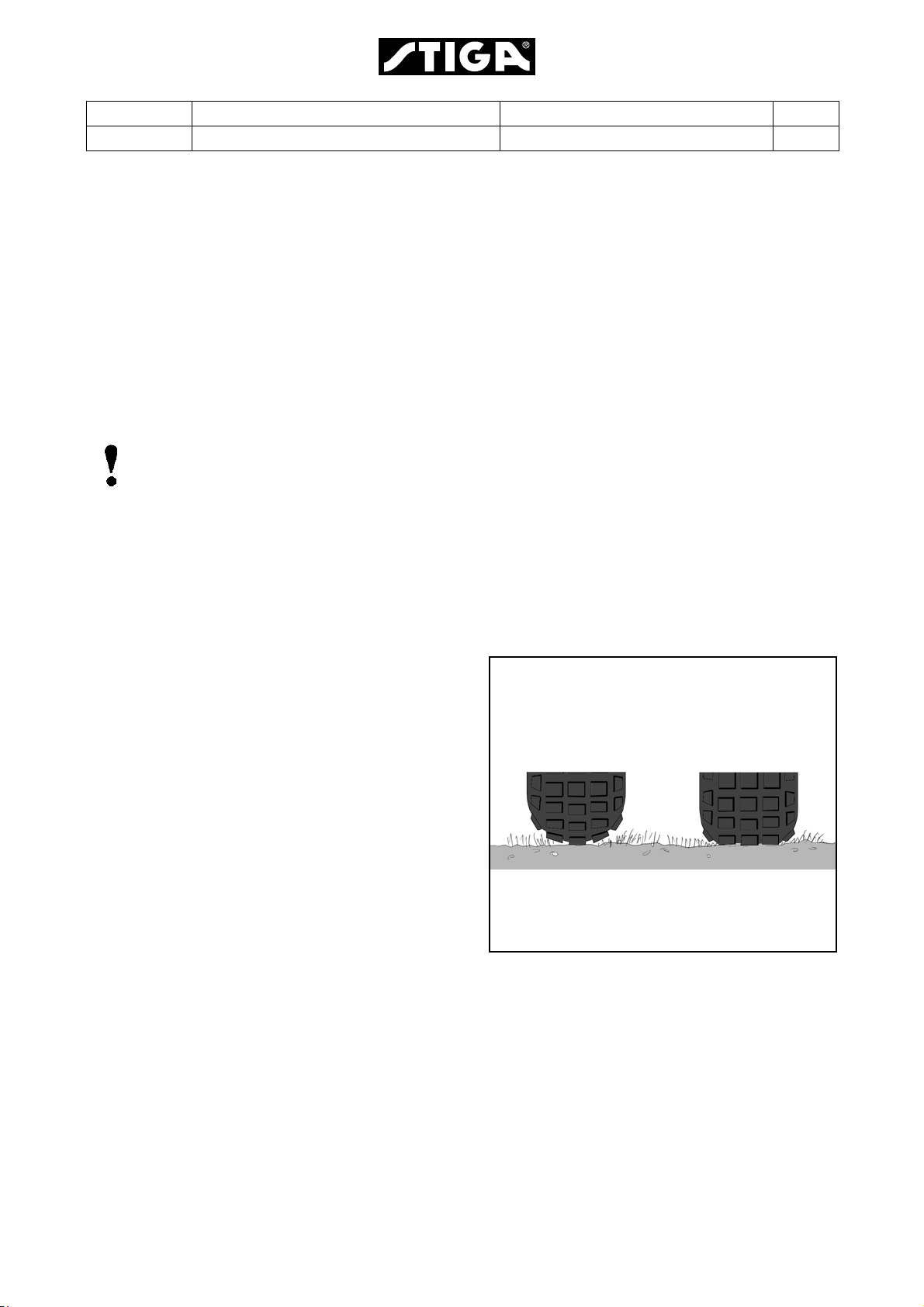
1. Check the air pressure in the tyres. The
pressure is designated on the floor mat.
The air pressure in the tyres is of critical
importance for the performance and
handling of the machine. The correct air
pressure for mowing is:
Front: 0,4 bar (6 psi)
Rear: 1,2 bar (17 psi)
When using some accessories it may be
necessary to increase the pressure
somewhat. However, the maximum
permitted pressure is always
1.2 bar (17 psi).
Too high pressure in the tyres leads to that
the machine drives poor due to:
• A small surface in contact to the ground.
• Hard tyre = less flexibility = self cleaning characteristic deteriorate.
Too high pressure Correct pressure
2. Remove the following parts from the
package and put them on the floor.
• The battery (some models).
• The steering wheel.
• The plastic bag, containing owners manuals,
and assembly screws.
Page 7

Edition Manual Chapter Page
2008-05-19 Workshop Manual, Stiga Villa/Ready 1 General 6
1.4.2 Battery
The battery is a valve regulated type.
Depending on the battery type, load and
assemble the battery, following the actual
instruction below.
Valve regulated battery
This battery needs limited maintenance. Is has
no electrolyte levels or plugs.
Warning!
Do not wear rings, metallic bracelet,
chain round the neck or similar metal
objects when working with the
battery. It can cause short-circuit,
burns and fire.
Warning!
The battery must be fully charged be-
fore being used for the first time. The
battery must always be stored fully
charged. If the battery is stored while
discharged, serious damage will occur.
Charging with the engine
The battery can be charged using the engine’s
generator as follows:
1. Install the battery in the machine as shown
below.
2. Place the machine outdoors or install an
extraction device for the exhaust fumes.
3. Start the engine according to the
instructions in the user guide.
4. Allow the engine to run continuously for 45
minutes.
5. Stop the engine. The battery will now be
fully charged.
Charging using battery charger
When charging using a battery charger, a
battery charger with constant voltage must
be used.
The battery can be damaged if a standard
type battery charger is used.
Installation of battery
See also the respective installation
manual, delivered with the machine.
After the battery is charged, remove the
motor casing and install it in the machine.
Connect first the red cable to plus (+) and
then the black cable to minus (-).
If the cables are disconnected/
connected in the wrong order,
there is a risk of a short-circuit
and damage to the battery.
If the cables are interchanged,
the generator and the battery
will be damaged.
The engine must never be driven
with the battery disconnected.
There is a risk of serious damage to the generator and the
electrical system.
Page 8
Edition Manual Chapter Page
2008-05-19 Workshop Manual, Stiga Villa/Ready 1 General 7
1.4.3 Assembly
The assembly procedure shall take place in a
clean, well illuminated and dry place.
Assemble the machine as follows:
Assembly of steering wheel
The machine is delivered with two shims, one
with a thickness of 0.5 mm and one with a
thickness of 1.0 mm.
In order to minimise the axial play in the
steering column, the shim washers (0.5 mm)
and/or (1.0 mm) must be installed on the
steering column between the steering column
jacket and the bracket as follows.
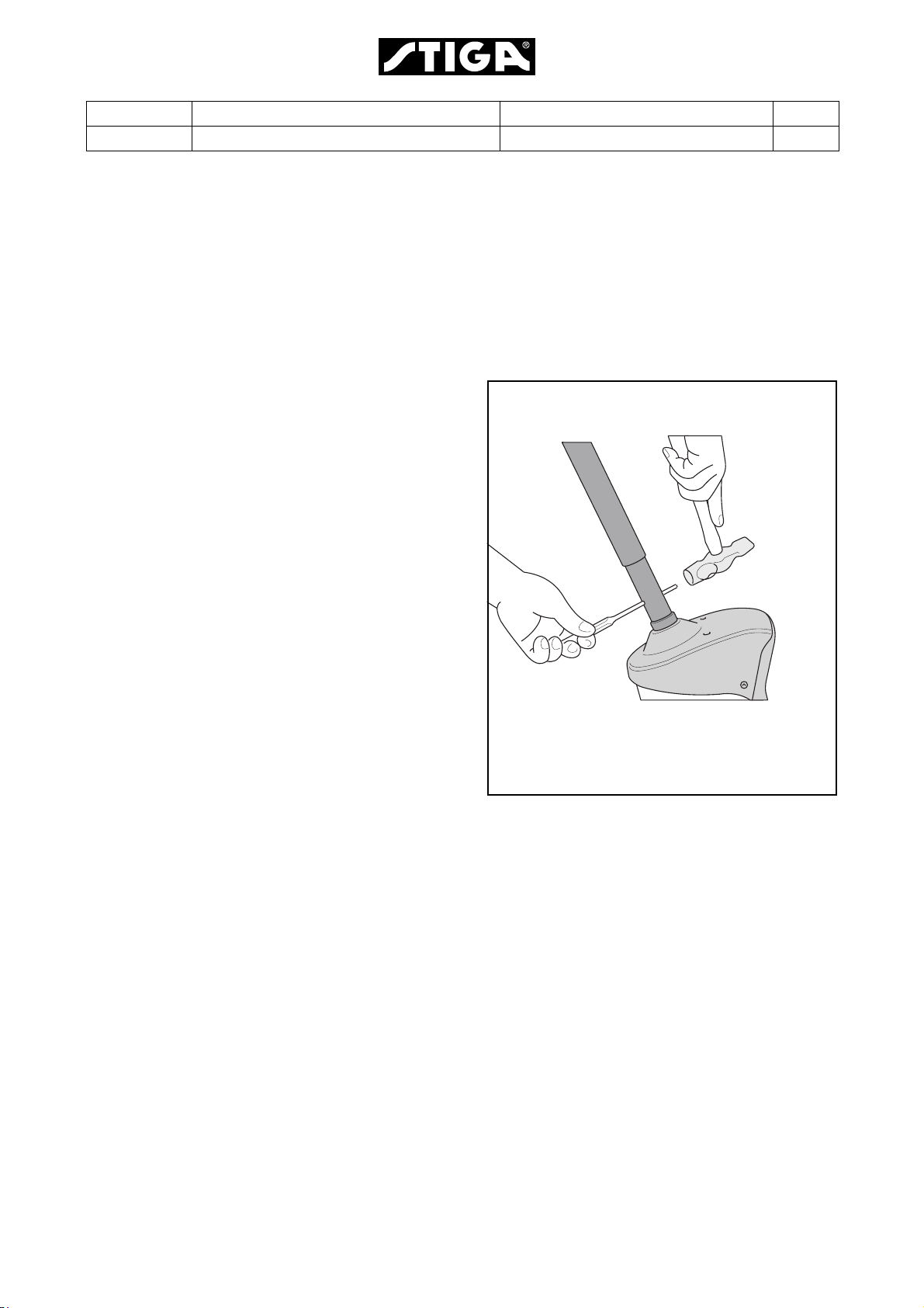
1. Install the steering column jacket on the
steering column and secure by knocking in
the tension pin approximately 1/3 of its
length.
2. Pull the steering column jacket and the
steering column up.
3. From the outside, check whether no
washers, the 0.5 mm washer, the 1.0 mm
washer or both washers can be inserted into
the gap. The washer/washers must not be
forced in, as there must be a little axial play.
4. Pull out the cotter pin and dismantle the
steering wheel jacket.
5. Install the washer/washers in accordance
with point 3 above.
6. Install the steering column jacket on the
steering column and secure by knocking in
the tension pin fully. Use a counterhold.
Also make sure that the logo on the steering
wheel is in the correct position.
Page 9
Edition Manual Chapter Page
2008-05-19 Workshop Manual, Stiga Villa/Ready 1 General 8
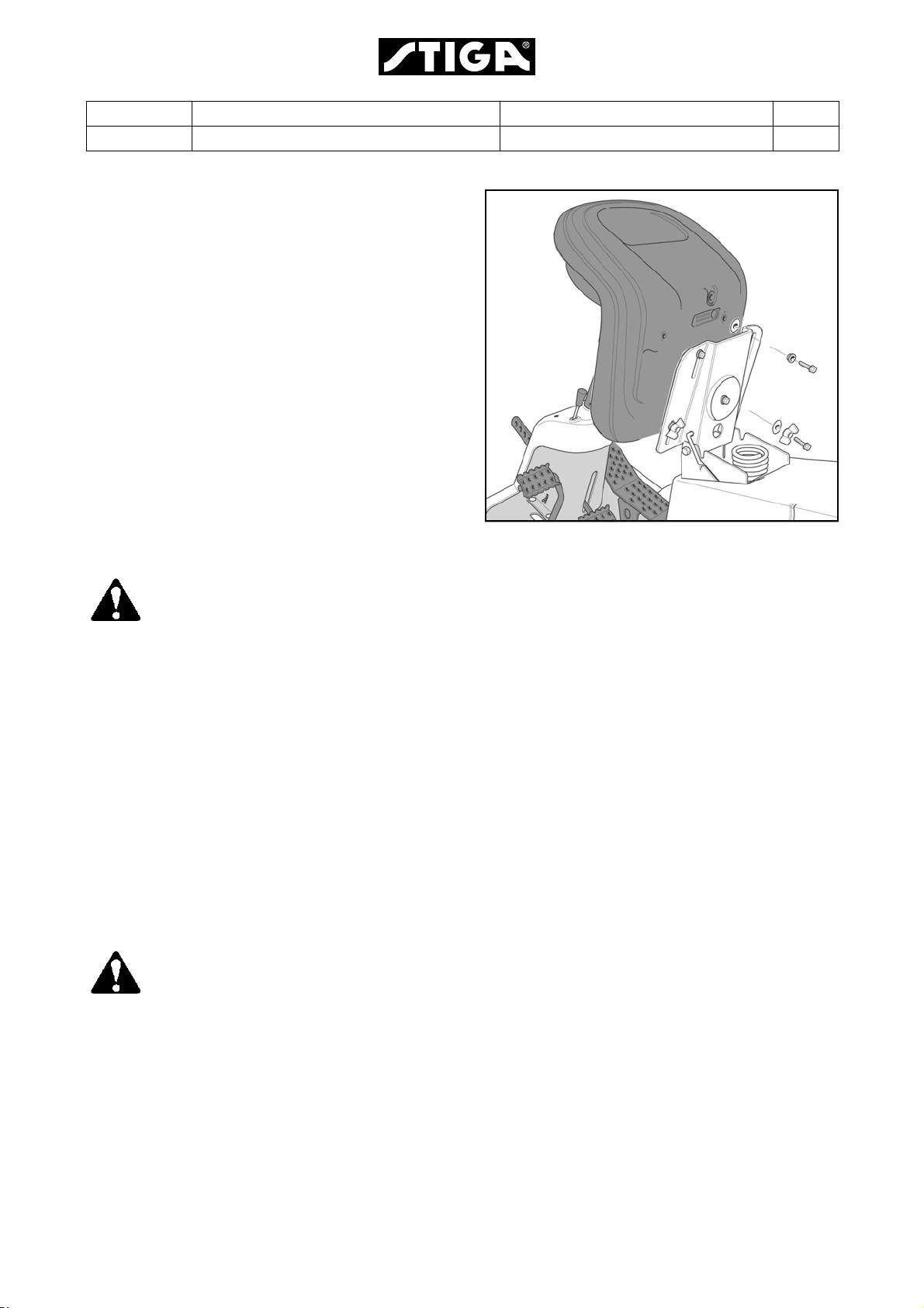
Assembly of seat (adjusting wings under)
Release the catch (S) and fold up the seat
bracket.
NOTE! To facilitate installation of the seat,
apply a drop of oil to the four screws before
I
screwing them into the seat.
F
Install the mounting in the rear (upper) holes as
follows:
K
1. Install the shoulder washers (F) on the screws
(K).
2. Insert the screws through the slots in the
bracket. Place a washer (I) between the seat
and the bracket.
3. Tighten the screws in the seat. Tightening
torque: 9±1.7 Nm.
If the screws are tightened more than
9±1.7 Nm, the seat will be damaged.
4. Check that the seat moves easily in the slots
in the bracket.
Install the mounting in the front (lower) holes as
follows:
1. Install the screw knobs (H) on the screws (G).
2. Install a washer (I) on each screw.
3. Insert the screws through the slots in the
bracket and tighten by hand in the seat.
I
H
G
S
4. Fold the seat down and place it in the desired
position.
5. Tighten the screw knobs (H) by hand.
The screw knobs (H) and the seat will
be damaged if tools are used.
Towing plate
Fitting according to customer requirements.
Engine oil
Check the oil level in the engine and top up if
necessary.
Page 10

Edition Manual Chapter Page
2008-05-19 Workshop Manual, Stiga Villa/Ready 1 General 9
1.4.4 Final checks
Removing from pallet
All the above measures shall have been done
with the machine standing on the pallet. Now,
loosen ev. remaining attachments and roll off
the machine from the pallet.
Accessories
Fit and adjust accessories.
Test driving
Warning!
Do not drive without a work
equipment (mover deck) attached.
Risk for turning over.
Drive the machine for a few minutes. Test all
the functions. Pay special attention to the
safety functions. If the machine is to be
delivered with mower deck or other
accessories, fit these before test driving the
machine.
Steering chain / Steering wire
Check that the steering chain / steering
wire is sufficiently taut. Adjust if
necessary.
Miscellaneous
Give the machine a general inspection.
• Is the machine clean?
• Is there any oil leakage?
• Abnormal noise or rattle?
Receipt
By filling in the guarantee certificate you
guarantee that the delivery service has
been correctly conducted.
Remember to make sure that the
customer receives all the documentation
when the machine is collected / delivered.
HST oil
Check the oil level in the HST’s expansion tank
after test driving, and top up if necessary.
Page 11

Edition Manual Chapter Page
f
T
a
T
2008-05-19 Workshop Manual, Stiga Villa/Ready 1 General 10
1.5 Service
Every new machine is delivered with a service book. This service book is part of the active
post-market programme and shall be kept in a safe place during the entire lifetime of the
machine. Hand over the service book if the machine is sold in 2:nd hand.
Service should generally be carried out at least every 50 operating hours (exception of the
irst service), although in accordance with the conditions below.
here are three different grades of service events. Every service event consists of a
number of service points as described in the following paragraphs. Every service point has
number which refer to a describing text after the schedules.
Some service points do not coincide with the scheduled service intervals, but shall be
performed in connection with a scheduled service when possible. E.g. some items shall be
performed at every second service and some also between two services. These service
points are described with procedure and interval in the respective “Instruction for use”.
ypical service points wich not coincide with scheduled service intervals are:
• Cleaning/changing air filter in some motors.
• Change of oil in some motors.
• Valve adjustments for some motors.
• Change of spark plug in some motors.
Page 12

Edition Manual Chapter Page
1.5.1 First S
1.5.2 Int
2008-05-19 Workshop Manual, Stiga Villa/Ready 1 General 11
The first service shall be performed within 5
hours of running and includes the service
points as per the table below.
This service is very important to safeguard
the continuing function of the machine.
Number Service point
1
2
3
4
5
6
21
ervice
Safety check.
Tyres, air pressure.
Engine oil, change.
Machines with filter, replace it
together with the oil.
Oil level in HST, check
(Valid for machines with HST
only).
Belt transmissions, check.
Steering adjustment.
Test driving.
ermediate Service
The intermediate service shall be conducted
between two basic services. That means 50
hours after a basic service.
Number Service point
1
2
3
4
6
8
11
12
The intermediate service is not as extensive
as the Basic Service and can therefore be
conducted by the customer, or by an
authorised Service Workshop. Regardless of
who conducts the service, it must be
documented in the service book.
Safety check.
Tyres, air pressure.
Engine oil, change.
Oil level in HST, check.
(Valid for machines with HST
only).
Steering adjustment.
Air filter, cleaning.
Cooling fins, clean.
Lubrication
Page 13

Edition Manual Chapter Page
2008-05-19 Workshop Manual, Stiga Villa/Ready 1 General 12
1.5.3 Basic Service
The basic service shall be conducted every 100
hours or once every year, which first occur.
The Basic Service must always be conducted by
an authorized Service Workshop, and
documented with a stamp in the service book.
Number Service item
1 Safety check
2
3
4
5
6
8
*) See also “Safety check”.
**) See also the mover deck manual.
Tires, air pressure
Engine oil, change.
Machines with filter, replace it
together with the oil.
Oil in HST, check.
Belt transmissions, check
Steering adjustment
Air filter for engine, clean/
replace
Number Service item
10
11
13
14
15
16
17
18
19
20
21
22
23
Cooling fins, clean
Spark plug, check/replace
Transmission, check
Speed check
Bearing boxes, check**
Exhaust system, check*
Electrical system, check*
Mower deck, check**
Blades, check**
Power take-off, check
Control check
Valve play***
Test driving
***) See the motor manual.
Page 14
Edition Manual Chapter Page
2008-05-19 Workshop Manual, Stiga Villa/Ready 1 General 13
1.5.4 Description of service points
1. Safety check
Check the safety functions. It is often appropriate to do this check in conjunction with test
driving. The following items shall be checked at all machines:
• No leakage on fuel lines and connections.
• No mechanical damages to the electrical cables. All insulation intact.
• The muffler shall be undamaged and its screws tightened. No exhaust leakage in connections.
The electrical check items at the respective machine up to model 2004 are listed in the
tables below. For models 2005 and up, see the respective “Instructions for use”.
Models with manual gearbox
Test Status Action Result
1 PTO activated.
No gear activated.
2 PTO not activated.
A gear is activated.
3 Motor running.
PTO activated.
4 Motor running.
A gear activated.
5 Motor running. Disconnect cable from the
Turn the key and make a
start attempt.
Turn the key and make a
start attempt.
Operator rises from the
seat.
Operator rises from the
seat.
shut off valve.
Motor shall not
start.
Motor shall not
start.
Motor shall
stop.
Motor shall
stop.
Motor shall
stop after a few
minutes.
HST models
Test Status Action Result
1 Brake pedal not pressed.
PTO not activated.
2 Brake pedal pressed.
PTO activated.
3 Motor running.
PTO activated.
4 Motor running. Disconnect cable from the
Turn the key and make a
start attempt.
Turn the key and make a
start attempt.
Operator rises from the
seat.
shut off valve.
Motor shall not
start.
Motor shall not
start.
Motor shall
stop.
Motor shall
stop after a few
minutes.
Page 15

Edition Manual Chapter Page
2008-05-19 Workshop Manual, Stiga Villa/Ready 1 General 14
2 Tyres, air pressure
Check the air pressure. Adjust if necessary.
The recommended air presure is
designated at the floor mat.
3 Engine oil and oil filter
See “Motors” at page 18. and the
“Instructions for use”, delivered with the
machine, see “Instructions for use” at
page 19. See also the engine manufacturer
manual.
4 Oil, HST
See the “Instructions for use”, delivered
with the machine.
5 Belt transmissions, check
Check the condition of all the belts and belt
tensioners.
11 Spark plug
Remove the spark plug and clean it or
replace if necessary. See also the engine
manufacturer manual.
12 Lubrication
Lubricate the 5 nipples and all moving
parts such as wires and levers. See
section 2.
13 Transmission
Listen for abnormal noise.
Manual models: Check that the drive
function works properly at all gears. Adjust
if required.
14 Speed check
Check that the speed corresponds to the
specified value.
6 Steering, adjustment
See section 3.
7 Not applicable
8 Engine air filter
See the “Instructions for use”, delivered
with the machine. See also the engine
manufacturer manual.
9 Not applicable
10 Cooling fins
Remove protective covers from the engine
and cleans between cooling fins. Use a
brush and compressed air. See also the
engine manufacturer manual.
15 Bearing boxes
Listen for abnormal noise from the
bearings. Check that there are no wear,
play or seizure.
16 Exhaust system
Check that there are no cracks, leakage or
other damages. Check the attachment
devices. See also the engine
manufacturer manual.
17 Electrical system
Check that there are no damaged cables,
contacts or other devices. Check that all
cables are properly secured to the chassis
and with cable holders. Check that there is
no friction between cables and chassis,
which can result in cable damage and
short circuit.
Page 16

Edition Manual Chapter Page
2008-05-19 Workshop Manual, Stiga Villa/Ready 1 General 15
18 Mower deck
Warning!
The blades are sharp. Always
wear gloves when working with
the blades to avoid injury.
Check if there are collision damages or
wear at the deck body and painting. Align,
repair and touch up the painting as
required.
Check the tightening of the bearing boxes
screws and tighten.
Rotate the blades and check the the shafts
are correct, not bent, no abnormal bearing
noise and no plays.
Check the belts and their tensions, see
section 4.
Check that the lifting mechanism moves
evenly, not jammed and no play and that it
locks in desired position.
20 Power take-off (PTO)
Check that the magnetic clutch (if
applicable) engage the work equipment
rotation in the desired time and that it not
slips during normal load. Replace the
clutch if necessary.
Check that the power take-off belt (if
applicable) engage the work equipment
rotation in the desired time and that it not
slips during normal load. Adjust if
necessary. See section 5.
Check that the power take-off brake (if
applicable) brakes the rotation movement
in the desired time. Adjust if necessary.
See section 5.
21 Control check
Check that all controls function properly,
that there are no jammings or excessive
plays. Adjust if nesaccary. See section 6.
Check the electrical function of the
electrical mower lifter (if applicable).
Check the plastic guide bar between the
blades. Replace if required.
19 Blades
Warning!
The blades are sharp. Always
wear gloves when working with
the blades to avoid injury.
Check that the blades are sharp. Replace if
necessary.
22 Valve play
See the engine manual regarding
procedure and interval.
23 Test driving
Drive the machine during a few minutes
and make the following attentions in
different speeds and turnings in right and
left. Check that all functions work evenly
and proper and without any abnormal
noise.
• Brake function
• Clutch function
•Power take-off
• Steering
Check that there are no abnormal
vibrations.
Page 17

Edition Manual Chapter Page
2008-05-19 Workshop Manual, Stiga Villa/Ready 1 General 16
1.6 Technical specifications
Tightening torques
6.1 General tightening torque
1.
Unless otherwise stated, the following tightening
torque are applicable for screws and nuts on the
machine:
Thread Torque
M5 5 Nm
M6 9 Nm
M8 22 Nm
M10 45 Nm
Page 18

Edition Manual Chapter Page
2008-05-19 Workshop Manual, Stiga Villa/Ready 2 Chassis and Body 1
2 Chassis and body
Contents in this chapter
2.1 Lifting mechanism,
manual ..........................................2
2.1.1 General.....................................2
2.1.2 Description................................2
2.1.3 Dismantling...............................2
2.1.4 Repair of lifting lock ..................6
2.1.5 Assembly ..................................6
2.2 Lubrication chassis .................... 8
2.2.1 Steering pivot pins
and beam pivot........................ 8
2.2.2 Control wires............................ 8
2.2.3 Tensioning arms ...................... 9
2.2.4 Steering chain.......................... 9
2.2.5 Bearings................................... 9
General
To facilitate the driving, handling of work equipment and to make it comfortable for the
driver, the machines are equipped with a various number of aid equipments. These
equipments are mainly the same for all the machines covered by this manual, but in some
cases configurated in different ways. Where divergences occour between the machines,
particular instructions are given for each particular equipment.
This chapter gives a brief description of the equipments and describes their repair and
replacements.
Page 19
Edition Manual Chapter Page
2008-05-19 Workshop Manual, Stiga Villa/Ready 2 Chassis and Body 2
2.1 Lifting mechanism,
manual
2.1.1 Description
The work equipment lifting arm is automatic
locked in elevated position by pressing down
the lifting pedal. Next time the pedal is pressed,
the mechanism will release and the arm drops
down.
The locking function is created in the lifting lock.
The principle is described below and shown in
the figure.
A. Locked in lifted position by the ratchet (C).
B. Unlocked. Ratchet (C) is released.
C. Ratchet which is tilted by the pin (D) every
time the pedal is pressed down.
2.1.2 Dismantling
To dismantle the lifting lock it is normally
necessary to dismantle the steering console.
Nevertheless, it is possible for a skilful person
to dismantle the lifting lock without releasing
the steering console.
C
C
D
AB
The dismantling is performed as follows:
1. Dismantle the steering wheel by tapping out
the pin.
If applicable, observe the spacers and the
location when disassembly the steering
wheel.
See section 1.
Page 20
Edition Manual Chapter Page
2008-05-19 Workshop Manual, Stiga Villa/Ready 2 Chassis and Body 3
2. Remove the screws for the top cover.
If applicable, remove also the following:
• The bullet from the throttle handle by twisting and pulling it simultaneously.
• The ignition switch nut. To aviod damage
at the plastic cover, use a 22 mm ring
wrench.
• The cutting heigth switch by pressing its
locking tabs at the underside.
3. Dismantle the front cover by unscrewing the
two screws at the under side.
4. Unhook the return spring.
Page 21

Edition Manual Chapter Page
2008-05-19 Workshop Manual, Stiga Villa/Ready 2 Chassis and Body 4
5. Dismantle the lifting pedal located on the lifting arm.
6. Loosen the throttle control as follows:
1. Loosen the lever.
2. Observe where the wire conductor is
fitted to reassemble in the same position.
7. Remove the screws that hold the steering
console at the floor plate, and lift off the
steering console.
8. Remove the screws that hold the lifting fork
at the lifting lock.
Page 22

Edition Manual Chapter Page
2008-05-19 Workshop Manual, Stiga Villa/Ready 2 Chassis and Body 5
9. Remove the nut that holds the lifting lock on
the underside of the floor plate, and remove
the lifting lock.
10.Carefully dismantle the left bearing in the
support with a screwdriver.
11.Remove the lifting fork from the support.
Page 23

Edition Manual Chapter Page
2008-05-19 Workshop Manual, Stiga Villa/Ready 2 Chassis and Body 6
2.1.3 Repair of lifting lock
The lifting lock can be purchased as a complete
spare part.
The parts can be lubricated with a thin
lubricant, e.g. silicon spray, 5-56, WD40, or the
like, if the lock jams.
Note!
Viscous lubricant such as consistent
grease must not be used.
2.1.4 Assembly
Assemble in reverse order.
Check that the accessory lifter functions as
intended by repeatedly lifting and lowering it.
Note!
Pay attention to the following notes
during the assembly:
A. Apply a thin layer of universal grease to the
plastic bushings at the lifter arm.
B. It does not matter how the lifting lock
is fitted since it is symmetrical.
UNIVERSAL GREASE
Page 24

Edition Manual Chapter Page
2008-05-19 Workshop Manual, Stiga Villa/Ready 2 Chassis and Body 7
C. When fitting the throttle control, install the
wire conduit as observed at the dismantling.
D. Fit the top cover before the consol screws
are tightened.
The consol is aligned against the top cover.
E. If applicable, observe the spacers and the
location when reassembly the steering
wheel.
See section 1.
Page 25

Edition Manual Chapter Page
2008-05-19 Workshop Manual, Stiga Villa/Ready 2 Chassis and Body 8
2.2 Lubrication chassis
All moving parts shall be lubricated once per
season, although at least every 50 operating
hours.
Note!
Lubrication is equally important for a
machine that is only used for a few hours
per year.
Note!
The lubricant provides not only
protection from wear but also from rust.
Note!
The machine should always be
lubricated before prolonged storage.
2.2.1 Steering pivot pins and beam
pivot
Use a grease gun, filled with universal grease
and lubricate the steering pivot pins (A) and the
beam pivot (B). Lubricate until grease
emerges.
Note!
To lubricate the beam pivot (B) it might
be nessecary to dismount the towing
hitch.
2.2.2 Implement mountings
Lubricate the lubricating cup for the mountings
using a grease gun until grease penetrates
along side the shaft.
A
B
A
Page 26

Edition Manual Chapter Page
2008-05-19 Workshop Manual, Stiga Villa/Ready 2 Chassis and Body 9
2.2.3 Control wires
Drop a little unversal oil or lubricating spray in
the ends of the control wires two or three times
a year.
This procedure must be carried out by two
persons. One lubricates and one activates the
lever
Note!
Wires on machines used in freezing
conditions should not be lubricated with
engine oil since this can lead to the
control cables seizing in the cold.
The wires on such machines should be
lubricated with a fluent, strongly
penetrating lubricant, e.g. 5-56 or WD40.
2.2.4 Tensioning arms
Lubricate the bearing points with an oil can
when each control is activated. Ideally carried
out by two persons.
2.2.5 Steering chain
The steering chain must be lubricated with
chain spray two or three times per season.
If the chains are heavily fouled: dismantle the
chains and wash them.
Refit and lubricate them.
2.2.6 Bearings
Plastic bearings, e.g. the brake pedal bearing,
hydrogear pedal bearing and steering-column
bearing, must be lubricated with grease or
lubricating spray at least once per year.
Page 27

Edition Manual Chapter Page
2008-05-19 Workshop Manual, Stiga Villa/Ready 3 Steering 1
3 Steering
Contents in this chapter
3.1 Steering wire/chain....................2
3.1.1 Description .............................2
3.1.2 Dismantling.............................2
3.1.3 Assembly................................3
3.1.4 Steering pulleys......................5
3.1.5 Adjusting the steering wire .....5
3.2 Bearings, steering shaft........... 6
3.2.1 Replacement of sliding
bearings................................. 6
General
The Villa and Ready machines are equipped with a mechanical steering system, working
with wires or chains, depending on the model.
This chapter contains a brief description of the function and describes repair, replacements
and adjustments of stressed parts of the steering system.
This chapter is valid for the actual machines where the actual system occur.
Page 28

Edition Manual Chapter Page
2008-05-19 Workshop Manual, Stiga Villa/Ready 3 Steering 2
3.1 Steering wire/chain
3.1.1 Description
There are two configurations regarding to
transmit the steering power from the steering
wheel to the rear wheels:
• Wire; One single wire with a defined location
at the drive pulley.
• Chain/wire; Two wires, left and right, fitted to
a chain which is connected to the steering
pulley.
3.1.2 Dismantling
1. Wire:
Remove the four steering pulleys (A and B).
Use a 15 mm and a 17 mm wrench.
Chain/Wire:
Remove the two steering pulleys (A). Use a
15 mm and a 17 mm wrench.
2. Remove the nut and screw, holding the wire
ends (C). Use a 13 mm wrench and a pliers
to hold the wire ends.
AB
BA
3. Remove the wire from the machine.
Wire:
Pull out the wire rivet from the steering pulley
and release the wire.
Chain/Wire:
Open the chain locks and release the wires
from the chain.
Wire
Chain/Wire
Page 29

Edition Manual Chapter Page
2008-05-19 Workshop Manual, Stiga Villa/Ready 3 Steering 3
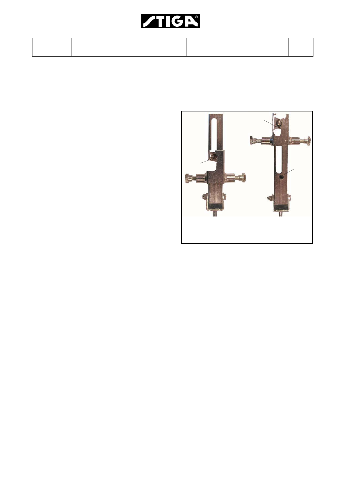
3.1.3 Assembly
One single wire
1. Assemble the left wire part into the two left
steering pulleys (A and B). Fit the pulleys into
their respective place.
See “3.1.4 Steering pulleys”.
2. Locate the wire in the recess (C) in the
steering disc and fasten with the screw. Use
a 13 mm wrench and a pliers to hold the wire
ends.
3. Turn the steering wheel until the wire rivet
hole is facing backwards and push in the
rivet.
4. Turn carefully the steering wheel 1,5 turn to
the left and simultaneously check that the
wire winds up correctly upwards on the drive
pulley.
Keep the left wire part stretched by blocking
or holding the rear wheels.
ABC
5. Assemble the right wire part into the two right
steering pulleys (A and B). Fit the pulleys into
their respective place.
See “3.1.4 Steering pulleys”.
6. Turn the wire 1,5 turns to the right on the
drive pulley. Keep the wire stretched.
7. Keep the wire stretched and locate the wire
in the recess (D) in the steering disc and
fasten with the parts below. Use a 13 mm
wrench and a pliers to hold the wire ends.
•Spring
• Washer
• M8 self locking nut
Adjust the wire.
See “3.1.5 Adjusting the steering wire”.
BAD
Page 30

Edition Manual Chapter Page
2008-05-19 Workshop Manual, Stiga Villa/Ready 3 Steering 4
Chain/Wire
1. Assemble the left wire part into the left
steering pulley (AL). Fit the pulley into place.
See “3.1.4 Steering pulleys”.
2. Locate the wire in the recess (C) in the
steering disc and fasten with the screw. Use
a 13 mm wrench and a pliers to hold the wire
end.
3. Assemble the right wire part into the right
steering pulley (AR). Fit the pulley into place.
See “3.1.4 Steering pulleys”.
4. Connect the wires to the chain with the chain
locks.
C
AL
AR
5. Stretched up the wire and and locate it in the
recess (D) in the steering disc and fasten
with the parts below. Use a 13 mm wrench
and a pliers to hold the wire ends.
•Spring
• Washer
• M8 self locking nut
Adjust the wire.
See “3.1.5 Adjusting the steering wire”.
D
Page 31

Edition Manual Chapter Page
2008-05-19 Workshop Manual, Stiga Villa/Ready 3 Steering 5
3.1.4 Steering pulleys
Every singel steering pulley consists of the
following parts:
A. Screw
B. Cable holder
C. Bushing
D. Steering pulley
E. Part of the frame
F. N ut
AB CDEF
Assembly instructions:
• Check the wear, specially of the steering pulley, and replace defective parts.
• Apply a thin layer of machine oil to the bushing (C).
• The cable holder (B) shall be centered
according to the wire, i.e. the angles in the figure shall be equal.
B
3.1.5 Adjusting the steering wire
Screw the nut and compress the spring until its
length is 108 mm. Hold the wire with a pliers.
Turn the wheels fully out in both directions.
Check that there is no abnormal noise or
abnormal resistance.
Page 32

Edition Manual Chapter Page
2008-05-19 Workshop Manual, Stiga Villa/Ready 3 Steering 6
3.2 Bearings, steering shaft
The steering shaft bearings consist of two sliding bearings of the composite type (A and B).
3.2.1 Replacement of sliding bearings
1. Remove the steering wire or wires. See
“3.1.2 Dismantling”.
2. Remove the stering wheel. See section 1.
3. If the machine is equipped with chain and
wire, release the chain from the sprocket.
4. Pull out the steering rod (F) downwards.
Don´t remove the washers and spacer (C, D
and E).
5. Replace the two bearings (A and B).
6. Assemble the steering rod (F) with its washers and spacer (C, D and E).
7. Assemble the stering wheel. See section 1.
8. Instructions for the chain, if applicable:
A
B
C
D
E
F
A. Apply a mark with a marking pencil at the
middle link of the chain (ev. there already
is a mark).
B. Turn the steering wheel to stright forward
position, i.e. the logo shall be correct
readable from the operators position.
C. Connect the chain to the sprocket with the
mark (G) backwards.
9. Assemble the steering wire or wires. See
“3.1.3 Assembly”.
G
Page 33

Edition Manual Chapter Page
2008-05-19 Workshop Manual, Stiga Villa/Ready 4 Hydraulic System 1
4 Hydraulic system
Contents in this chapter
4.1 Safety..........................................2
4.2 Description.................................2
4.3 Repair .........................................2
4.4 HST oil ........................................3
4.4.1 General...................................3
4.4.2 Oil filling..................................3
General
The engine power in Villa and Ready machines are transfered by a 5 gear gearbox
alternatively a stepless hydrostatic transmission (HST) to the front wheels. The steering is
performed by the rear wheels.
This chapter contains a brief description of the hydrostatic transmission and the oil filling
procedure. Other measures are not applicable.
Page 34

Edition Manual Chapter Page
2008-05-19 Workshop Manual, Stiga Villa/Ready 4 Hydraulic System 2
4.1 Safety
Cleanliness is mandatory at all works with
the hydraulic system. Foreign substances
and contaminations will jeopardize the function and reliability of the system.
4.2 Description
The hydrostatic transmission (HST) consists of
a hydraulic pump and a hydraulic motor.
The hydraulic pump is mechanic connected to
the drive belt.
The powerfrom the pump is transmitted to the
motor by an oil flow, i.e. the transmission is
hydraulic.
The hydraulic motor is mechanic connected to
the wheel shaft.
Since both the oil flow and the flow direction is
controlled by the drive pedal, the machine can
move both forwards and backwards with a
stepless gear ratio.
4.3 Repair
Since trouble with the HST is very unusually,
there is no need for any repair instructions in
this book.
However, in some cases oil lekage can occur.
Therefor, the oil filling procedure is described
below.
Should major repair to the HST be needed,
please refer to the service provided of the
transmission manufacturer.
Page 35

Edition Manual Chapter Page
2008-05-19 Workshop Manual, Stiga Villa/Ready 4 Hydraulic System 3
4.4 HST oil
4.4.1 General
The HST casing is a sealed unit, which normally
not need any service. Oil filling is
recommended only if any of the cases or both
cases below are valid:
• There is a visible oil leakage.
• Drive problems.
4.4.2 Oil filling
Note!
It may be difficult to remove the entire
oil plug intact. It is recommended to
have a new plug available before
starting the oil filling.
1. Lift the machine.
2. Remove the oil plug.
The oil plug also works as a ventilation valve.
The oil plug consists of rubber and fits rather
hard in the housing hole.
Use a long pointed chisel to work up the
plug. Eventually, loosen the HST in the frame
and lower it for better access.
3. Check the oil level. Use a suitably bent steel
wire or similar.
The level shall reach up to just under the
lower part of the plug.
4. If neccesary, top up with new oil.
Use oil SAE 10W-40 or SAE 5W-50.
Elongate the discharge of an oil can with a
plastic hose of suitable length and diameter.
Put the other end into the HST oil hole and
pump until the oil flows over.
5. Fit a new oil plug and assemble in reverse
order.
Page 36

Edition Manual Chapter Page
2008-05-19 Workshop Manual, Stiga Villa/Ready 5 Belts 1
5 Belts
Contents in this chapter
5.1 Description.................................2
5.2 Belt theory..................................3
5.2.1 Why it is so important to use
original belts from
the retail dealer? ..................... 3
5.3 Replacement of belts................5
5.3.1 Disassembly of belt D ............ 5
5.3.2 Inspection and measures ....... 7
5.3.3 Assembly of belt D ................. 7
5.4 Adjustments...............................9
5.4.1 Adjustment of belt B ...............9
5.4.2 Adjustment of the
clutch/brake, HST.................... 10
5.4.3 Adjustment of the clutch, Man 10
General
All mechanical power, delivered by the motor, is conducted to the different power
consuments by a belt system. The belt system has in general the same configuration in all
the machines covered by this manual. Where divergences occour between the machines,
particular instructions are given for each machine. The maximum tension of each belt is
regulated by a spring loaded belt tensioner.
This chapter gives a brief description of the belt system and describes replacements of
belts and adjustments of their tensions.
This chapter is valid for the actual machines where the actual system occur.
Page 37

Edition Manual Chapter Page
2008-05-19 Workshop Manual, Stiga Villa/Ready 5 Belts 2
5.1 Description
AB
123 45678
Belt A
Belt A belongs to the work equipment and is
connected to the machine at the front right
pulley. The belt is tensioned by the tension
pulley (2) which is mounted on a spring
loaded lever.
Belt B
Belt B is intended to deliver motor power to
the front right pulley, where it can be picked
up of the work equipment.
Belt C
Belt C transmitts the power to belt B and
performs the mechanic PTO clutch function
together with the pulley (8).
Engagement/disengagement of the
mechanic PTO is performed by moving the
pulley (8) to stretch/slacken the belt.
Belt D
Belt D is intended to transmitt the motor
power to the transmission, where it is geared
to a suitable ratio for the drive shaft. The belt
is tensioned by the tension pulley (7) which
together with the belt performs the clutch
function.
D
C
Motor
10
9
Belts:
A. Work equipment belt (belongs to the
work equipment).
B. Work equipment belt.
C. Work equipment clutch belt.
D. Transmission belt.
Pulleys:
1. Pulley at the work equipment.
2. Tension pulley.
3. Pulley (double).
4. Pulley at the transmission.
5. Tension pulley with the clutch function
(works on the same lever as pulley 7).
6. Transmission pulley (double).
7. Tension pulley with the clutch function
(works on the same lever as pulley 5).
8. Tension pulley (for mechanic PTO also
clutch pulley for the PTO)
9. Drive pulley at the motor shaft.
10.Drive pulley at the motor shaft.
The tensioning force is disengaged from the
belt when the parking brake is activated.
Page 38

Edition Manual Chapter Page
2008-05-19 Workshop Manual, Stiga Villa/Ready 5 Belts 3
5.2 Belt theory
5.2.1 Why it is so important to use original belts from the retail dealer?
The table below shows the demands on normal commercial grade belts compared to
demands on original spare parts belts from the retail dealer. The later are designed and
manufactured in close connection between the subcontractor and the rider manufacturer.
The table is intended to display the importance to use the original belts.
Case Commercial
grade belts
Fitness to pulleys. The belt shall rest
with its angled
sides against the
pulleys. There
must be a space
between belt and
pulley bottom.
Acceleration. The belt follows
the motor rpm in a
continuous
.
acceleration up to
full speed.
Original spare
parts belts
The belt shall rest
with its angled
sides against the
pulleys. There must
be a space
between belt and
pulley bottom.
Some belts shall
engage to the
pulleys with the
motor running in full
speed, which gives
an excessive
generation of heat.
Remarks
Same demands.
Original belts
guarantee that the belt
fits against the pulleys.
Common belts are
made of natural rubber,
which can resist
temperatures up to 70°
only.
Original belts are made
of chloroprene rubber,
which can resist
temperatures up to 90°
Length Manufactured in
standard lengths
in steps..
Manufactured in
preedefined lengths
to fit between the
pulleys..
The distance between
the pulleys is fix. The
belt tensioner gives the
original belt an optimal
tension.
Page 39

Edition Manual Chapter Page
2008-05-19 Workshop Manual, Stiga Villa/Ready 5 Belts 4
Case Commercial
grade belts
Floating pulley at
the implement.
Bending in two
directions
Designed to
transmit power
between aligned,
paralell and fixed
pulleys.
Designed to bend
around pulleys in
one direction only
Original spare
parts belts
The original PTO
belt is designed to
operate, even if the
pulleys are moving
up and down and
are tilting at the
same time
Most of the belts at
the machine have
tension rollers,
actuating from the
outside of the belt.
This means the the
belt has to bend
both inwards and
outwards during the
operation.
Remarks
The implement follows
the ground which
involves that its pulley
is constant moving.
To resist the excessive
operating conditions,
the original belts are
made of fibre
reinforced rubber.
All original belts which
operate with tension
rollers actuating from
the outside have
reinforcements. The
reinforcement is
special designed for
the actual case.
Noise Manufactured
without any
special respect to
the actual case.
The original belts
are carefully
selected to give the
lowest noise
increment to the
machine during
operation.
Depending on the
function of the belt, any
of the following belt
types are itemised:
• Wrapped
• Non-friction
• Raw-edge
Page 40

Edition Manual Chapter Page
2008-05-19 Workshop Manual, Stiga Villa/Ready 5 Belts 5
5.3 Replacement of belts
This section describes the belt changing of belt
D. For changing other belts, see actual parts of
the belt D description.
5.3.1 Disassembly of belt D
The belt D is intended to conduct the engine
power to the front driving (HST or manual
gearbox). The belt is controled by a 3-armed
lever for the clutch function.
Dismantle the belt as follows:
1. Raise the machine by one of the alternatives
below:
• With a highjack or similar and place 4
yokes under the shafts.
• With a lifting table.
2. Remove the following:
• Belt guides (X and Y)
• Pulley (8)
• Wire (Z) with its spring and adjuster.
E
D
CB
X
Y8Z
3. Cut off the holding strap (E) for the wire.
4. Unscrew the two screws and nuts, holding
the adjustable pulley bar (F). Remove the
pulley bar with belt C.
5. Unhook and work off the belt C.
F
Page 41

Edition Manual Chapter Page
2008-05-19 Workshop Manual, Stiga Villa/Ready 5 Belts 6
6. Unhook the clutch spring.
7. Remove the pulley (5). Use a 15 mm and a
17 mm wrench.
Note!
Pivot and belt guide nuts; Hold the nuts
at the upper side if nessecary.
5H
8. Loosen the pivot screw (H) a couple of turns.
9. Loosen the belt guide screw (I) a couple of
turns.
10.Remove the four front axle screws (J) and
heighten the body (or lower the
transmission) about 3 cm. Preferably put a 3
cm distance (K) between the axle and the
body at both sides.
Be carefully not to damage the transmission fan. A damaged fan will increase the heating and cause gearbox
damages.
I
K
J
J
K
11.Work off the belt D.
Page 42

Edition Manual Chapter Page
2008-05-19 Workshop Manual, Stiga Villa/Ready 5 Belts 7
5.3.2 Inspection and measures
1. Check and lubricate all links.
• The links shall move easily and not have
any major play.
• Lubricate all pivot linkages with machine
oil.
2. Check the belts.
• The belt shall rest with its angled sides
against the pulleys. There must be a
space between belt and pulley bottom.
• The belt shall be intact. No loose parts or
cracks.
3. Check all ball bearings with respect to the
following:
• No radial play.
• The sealing shall be intact.
• No abnormal noise when rotating. Shall
rotate evenly without stop tendency.
Replace all defective parts with genuine
spare parts.
5.3.3 Assembly of belt D
Assemble all part in the reverse order.
Note the following at the assembly procedure:
1. Be carefully not to damage the fan when
fitting the belt D around the transmission
pulley (4).
5
H
2. The belt guides shall be mounted with a play
of 2-3 mm to the belt when it is stretched.
3. If the screws (H and I) cannot be tightened,
hold the respective nut at the upper side.
I
Page 43

Edition Manual Chapter Page
2008-05-19 Workshop Manual, Stiga Villa/Ready 5 Belts 8
4. The pulleys (5 and 7) shall be mounted with
washer etc. as illustrated. The small pulley
shall face with its prolonged part
downwards.
7
5
5. The belt guide at pulley (7) shall be centered
over the belt when the clutch is engaged.
Note!
The prolonged part of the pulley hub
shall face against the lever.
E
7
Page 44

Edition Manual Chapter Page
2008-05-19 Workshop Manual, Stiga Villa/Ready 5 Belts 9
6. Don´t tighten the screws to the pulley bar (F)
yet. The belt adjustment must be performed
first.
7. Perform the adjustments as described
below.
5.4 Adjustments
5.4.1 Adjustment of belt B
Adjust the tension of belt B as follows:
1. Loosen the two screws (L and M) a few
turns.
2. Tension the belt by pulling the right end of
the pulley bar (F) backwards by using a
spring scale. Pull with a force of 85 N.
3. Tighten, simultaneously as the force is
applied, the two screws (L and M).
L
F
M
L
4. Fit a new fixing strap to the PTO wire.
VARNING!
If the fixing strap is omitted, the wire
will interfere with the steering wire
and be destroyed.
85 N
M
Page 45

Edition Manual Chapter Page
2008-05-19 Workshop Manual, Stiga Villa/Ready 5 Belts 10
5.4.2 Adjustment of the clutch/brake,
HST
Adjust the nuts (N1 + N2) at the clutch/brake
lever to a play of 3 mm between the lock pin
and the clutch lever.
After the adjustment, tighten the nuts (N1 +
N2).
5.4.3 Adjustment of the clutch, Man
Note!
Manual machines shall have 0 mm play
at the clutch rod (Q).
If the clutch not disengage the engine rotation
properly, it will be very difficult to change gears.
In that case, adjust the clutch as follows:
1. Hold the clutch rod (Q) with a polygrip and
loosen the rear nut (O2) until the clutch rod
(Q) is completely loose. Now, the belt
stretching will perform the stop for the clutch
arm (P). I.e the belt is max stretched by the
spring.
2. Screw the rear nut (O2) slowly forward until
the clutch arm (P) begin to move. Then
screw the nut one more turn. If nessecary,
move the front nut (O1) forwards.
N1 N2
O1 O2
3 mm
Q
P
0 mm
3. Lock by screwing the forward nut (O1)
backwards and tighten against the lever
loop. Hold the clutch rod (Q) with a polygrip
when tightening the nut.
Page 46

Edition Manual Chapter Page
2008-05-19 Workshop Manual, Stiga Villa/Ready 6 Control wires 1
6 Control Wires
Contents in this chapter
6.1 Description.................................2
6.2 Cable holders.............................2
6.3 PTO wire.....................................3
6.3.1 Dismantling.............................3
6.3.2 Checks ...................................3
6.3.3 Assembly................................3
6.3.4 Adjustment .............................3
6.4 Throttle wire .............................. 4
6.4.1 Dismantling ............................ 4
6.4.2 Assembly ............................... 4
6.4.3 Adjustment............................. 4
General
All the manoeuvring functions are collected around the operator.
All mechanical control movements from the operator to the respective device on the ma-
chine are conducted by wires or rods.
This chapter gives a brief description about the wires and information about how to re-
place and adjust the wires.
This chapter is valid for the actual machines where the actual system occur.
Page 47

Edition Manual Chapter Page
2008-05-19 Workshop Manual, Stiga Villa/Ready 6 Control wires 2
6.1 Description
All wires consist of a wire and a conduit. In the
wire ends one part, the wire or the conduit, is
fastened to the body and the other part to a lever. The levers are connected to the operator
control and to the controlled device. I.e. the
throttle wire, etc.
Wires can only transfer traction forces. The return forces for the wires are maintained by return springs.
To transfer higher forces and both pushing
and traction forces, rods are used, i.e. brakes,
etc.
Maintenance of wires:
Drop a little engine oil or lubricating spray in
the ends of the control wires two or three times
a year.
6.2 Cable holders
Warning!
It is essential that all cable holders
are fitted properly. If not, there is
risk of abnormal wear, short circuit
and fire.
All wires, electrical cables and other conductors are fitted to the chassis with cable holders. Always, after removal or replacement of
wires, new cable holders shall be fitted in places where they were original mounted.
Loose wires and cables cause unneseccary
wear of components which finally result in
electrical short circuit, paint removal and damages of plastic covers etc.
Page 48

Edition Manual Chapter Page
2008-05-19 Workshop Manual, Stiga Villa/Ready 6 Control wires 3
6.3 PTO wire
6.3.1 Dismantling
1. Lift the machine, either with a lifting table or
by highjack and pallets.
2. Open the engine casing.
3. Unscrew the cable adjustments, upper (A)
and lower (B).
4. Cut the holding strap (C) and unhook the
wire.
6.3.2 Checks
Check the brake shoe (D) for wear. If nessecary replace it.
A
D
6.3.3 Assembly
1. Apply a couple of oil at the wire ends while
moving it in its conduit.
2. Assemble in the reverse order.
Warning!
If the wire is loose, it will interfere with
the steering wire. It is therefore especially important that it is locked with a
new holding strap correctly.
3. Replace the holding strap (C).
4. Adjust the wire. See below.
6.3.4 Adjustment
1. Set the cable adjustments, upper (A) and
lower (B) in their middle positions.
2. Adjust about the same amount at both
adjustments until the lever have a play of
3-3,5 cm.
B
C
3-3,5 cm
3. Lock the adjustment nuts.
Page 49

Edition Manual Chapter Page
2008-05-19 Workshop Manual, Stiga Villa/Ready 6 Control wires 4
6.4 Throttle wire
6.4.1 Dismantling
1. Open the engine casing.
2. Loosen the wire conduit at the engine and
at the throttle lever. At machines with the
throttle lever in the front panel, remove the
upper casing for acess to the lever. See
section 2.
Note!
.It is not nessecary to cut the holding
strap (A).
3. Remove the wire.
A
6.4.2 Assembly
1. Apply a couple of oil at the wire ends while
moving it in its conduit.
2. Assemble in the reverse order.
3. Thread the wire through the holding strap
(A) and at machines with the throttle lever in
the front panel, through the holes (B).
4. Adjust the wire. See below.
6.4.3 Adjustment
1. Adjust the wire conduits at the ends until
the throttle lever can reach its end positions.
2. Fasten the conduit clamps.
3. Check the following:
• Function of the choke position
• Full throttle position
B
If nessecary repeat the adjustment procedure.
Page 50

Edition Manual Chapter Page
2008-05-19 Workshop Manual, Stiga Villa/Ready 7 Electrical System 1
7 Electrical System
Contents in this chapter
7.1 Description.................................2
7.2 Trouble Shooting ......................3
7.3 Repair and replacements..........16
7.3.1 Replacement of switches ....... 16
7.3.2 Replacement of switch knob .. 16
7.3.3 Connections ........................... 16
General
Each machine has its own electrical system, configurated to fit the purpose and demand of
the actual machine. The electrical system has two main duties, to maintain the machine
safety and to make the different functions easy to handle.
The main part of this chapter consists of trouble shooting of the electrical system to isolate
faults and to give information about corrective measures. The electrical system is also
described. There are also given instructions about general repair and replacement
procedures.
Page 51

Edition Manual Chapter Page
2008-05-19 Workshop Manual, Stiga Villa/Ready 7 Electrical System 2
7.1 Description
The electrical components are connected with cables, integrated in a complete insulated
harness, which is unique for each machine model. Thus the cables are protected against
wear, contaminations and other stresses. The cables are connected to the actual
components with tab or screw connectors and in some cases with multi-contact connectors.
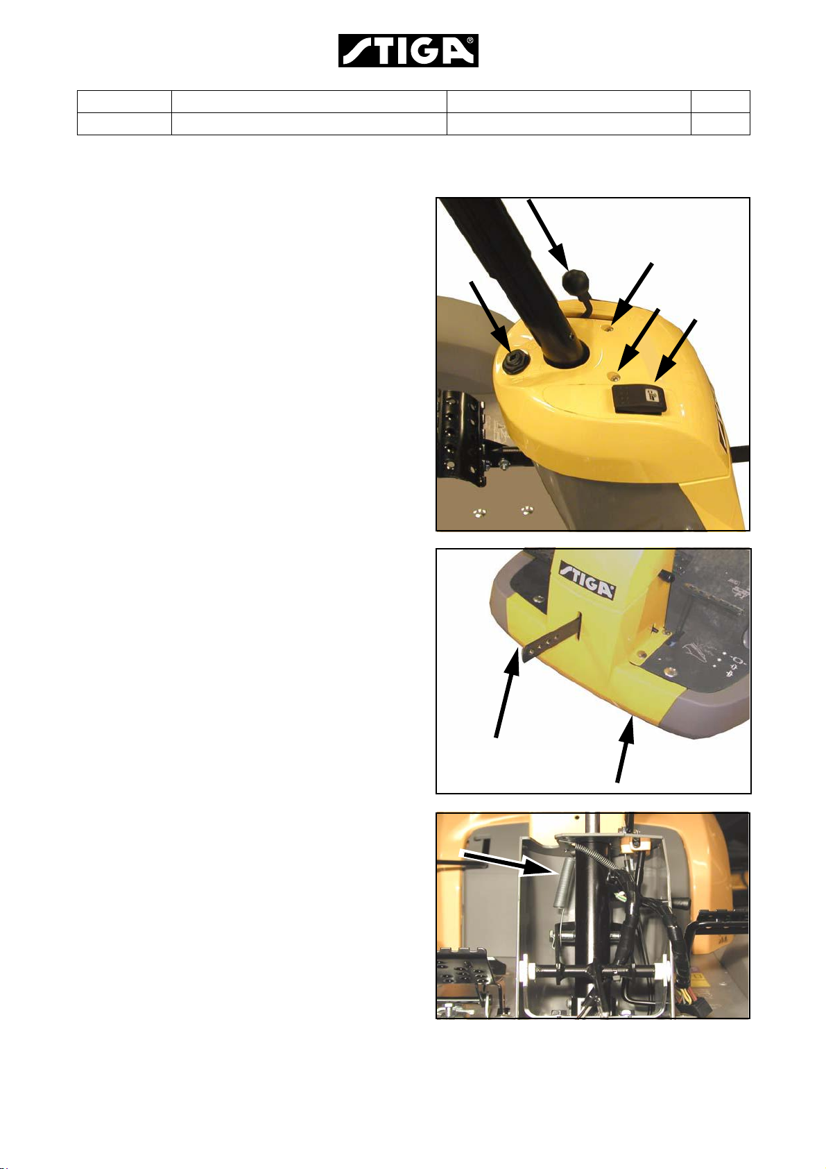
The electrical system contains several safety circuits. Therefore actual levers and pedals
are provided with micro switches. The micro switches are shown in the figure below. The
signals from the micro switches are used to interlock the actual circuit in case of a forbidden
manoeuvre attempt. Some manual switches and relays have also built in interlocks, related
to the safety system.
The wiring diagrams are presented separately in the respective spare parts manual. To
achieve a complete understanding of the electrical system for a certain machine, read also
the actual wiring diagram.
All current consumption circuits except the start circuit are protected by 1-3 fuses,
depending on the machine model.
Microswitch under the seat
Microswitch under the
control panel
Microswitch at the
brake pedal lever
Page 52

Edition Manual Chapter Page
2008-05-19 Workshop Manual, Stiga Villa/Ready 7 Electrical System 3
7.2 Trouble Shooting
Warning!
Do not wear rings, metallic bracelet, chain round the neck or similar metal
objects when working with the electrical system. It can cause short-circuit,
burns and fire.
This section describes the trouble shooting procedures in absence of an electrical function.
It also describes the correction measures in each actual case. When following the trouble
shooting schedules, it is provided that the following states are fulfilled:
• All fuses are checked and, if necessary replaced.
• The battery shall be charged.
• The requirements for the actual measure shall be fulfilled. E.g. if it is advised to perform a
start attempt, the operator shall sit down on the seat, press the brake pedal and the
power take off shall be in disengaged position.
When following the trouble shooting shedules, it is in normal cases assumed that
conductors and connectors to conductors are OK. However, in some cases, after a long
period of use or in case of mechanical damages, the cables at the articulating point can be
damaged. The circuit diagrams are presented in the respective spare parts manual.
The following operation faults for models 2002-2007 are described.
Paragraph Page
7.2.1 The starter does not rotate . . . . . . . . . . . . . . . . . . . . . . . . . . . . . .4
7.2.2 The starter rotate, but the motor does not start . . . . . . . . . . . . . .8
7.2.3 The battery runs repeatedly empty . . . . . . . . . . . . . . . . . . . . . . .10
7.2.4 The motor does not stop . . . . . . . . . . . . . . . . . . . . . . . . . . . . . . .11
7.2.5 Electric cutting height adjustment . . . . . . . . . . . . . . . . . . . . . . . .12
7.2.6 The PTO clutch does not engage . . . . . . . . . . . . . . . . . . . . . . . . 12
7.2.7 The motor can be started without the brake pedal is pressed . .13
7.2.8 The motor can be started with the mover deck activated . . . . . . 13
7.2.9 The motor can be started with a gear activated . . . . . . . . . . . . . 13
7.2.10 The motor does not stop when the operator leaves
the seat and the mover deck is activated . . . . . . . . . . . . . . . . . .14
7.2.11 The PTO clutch does not disengage when the operator
leaves the seat and the mover deck is activated . . . . . . . . . . . . .14
7.2.12 The motor does not stop after a few minutes
when the shut off valve cable is disconnected . . . . . . . . . . . . . .15
Page 53

Edition Manual Chapter Page
2008-05-19 Workshop Manual, Stiga Villa/Ready 7 Electrical System 4
7.2.13 The starter does not rotate
Ready Man, Villa 12r
B70
Page 54

Edition Manual Chapter Page
2008-05-19 Workshop Manual, Stiga Villa/Ready 7 Electrical System 5
Villa Comfort, Villa Elit
B50
Page 55

Edition Manual Chapter Page
2008-05-19 Workshop Manual, Stiga Villa/Ready 7 Electrical System 6
Ready HST, Villa 14 HST, Villa 16 HST
B71 89
Page 56

Edition Manual Chapter Page
2008-05-19 Workshop Manual, Stiga Villa/Ready 7 Electrical System 7
Villa de Lux, Villa Royal
B53 62
Page 57

Edition Manual Chapter Page
2008-05-19 Workshop Manual, Stiga Villa/Ready 7 Electrical System 8
7.2.14 The starter rotate, but the motor does not start
Ready Man, Villa 12, Villa Comfort, Villa Elit 14
B50 70
Ready HST, Villa 14 HST, Villa 16 HST
D71 89
Page 58

Edition Manual Chapter Page
2008-05-19 Workshop Manual, Stiga Villa/Ready 7 Electrical System 9
Villa de Lux, Villa Royal
D53 62
Page 59

Edition Manual Chapter Page
2008-05-19 Workshop Manual, Stiga Villa/Ready 7 Electrical System 10
7.2.15 The battery runs repeatedly empty
Ready Man, Ready HST, Villa 12, Villa 14 HST, Villa 16 HST, Villa Comfort, Villa Elit 14
A50 70 71 89
Villa de Lux
A62
Page 60

Edition Manual Chapter Page
2008-05-19 Workshop Manual, Stiga Villa/Ready 7 Electrical System 11
Villa Royal
A53
7.2.16 The motor does not stop
All machines
C alla
Page 61

Edition Manual Chapter Page
2008-05-19 Workshop Manual, Stiga Villa/Ready 7 Electrical System 12
7.2.17 Electric cutting height adjustment
G53
Page 62

Edition Manual Chapter Page
2008-05-19 Workshop Manual, Stiga Villa/Ready 7 Electrical System 13
7.2.18 The PTO clutch does not engage
Villa de Lux, Villa Royal
K53 62
PTO clutch characteristic
Due to high temperature and magnetic stress, the PTO clutch, after a long term
of use, can show up instability in the internal components. This can result in that
the clutch works properly when it is cold, but sometimes (not always) failures
after warming up.
Therefore, to be sure to isolate the fault, the PTO clutch must be checked in
both cold and warm condition; particular in warm condition.
Page 63

Edition Manual Chapter Page
2008-05-19 Workshop Manual, Stiga Villa/Ready 7 Electrical System 14
7.2.19 The motor can be started without the brake pedal is pressed
All machines except machines with manual gearboxex
H_Alla11
7.2.20 The motor can be started with the mover deck activated
All machines with mechanic PTO
H_ABDE12
7.2.21 The motor can be started with a gear activated
Machines with manual gearboxes
H_B13
Page 64

Edition Manual Chapter Page
2008-05-19 Workshop Manual, Stiga Villa/Ready 7 Electrical System 15
7.2.22 The motor does not stop when the operator leaves the seat and
the mover deck is activated
All machines with mechanic PTO
I_all14
7.2.23 The PTO clutch does not disengage when the operator leaves the
seat and the mover deck is activated
All machines with electric PTO clutch
I_CF15
7.2.24 The motor does not stop after a few minutes when the shut off
valve cable is disconnected
All machines with electric shut off valve in the fuel system
J_EDFC17
Page 65

Edition Manual Chapter Page
2008-05-19 Workshop Manual, Stiga Villa/Ready 7 Electrical System 16
7.3 Repair and replacements
Warning
Do not wear rings, metallic bracelet,
chain round the neck or similar metal objects when working with the
electrical system. It can cause shortcircuit, burns and fire.
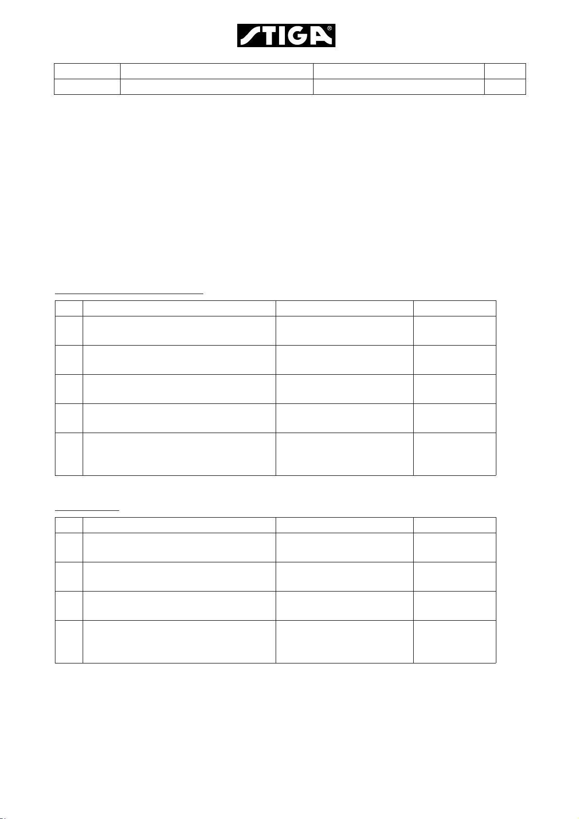
7.3.1 Replacement of switches
All switches are pressed into place in their
rectangular holes at the control panel. To
change a switch proceed as follows:
1. Remove the actual cover to get access to
the switch.
2. Press the fixation pig at the connector and
pull the connector from the switch.
See the figure.
Some connectors have 2 pigs.
3. Press the fixation tongues on both sides of
the switch against the switch. Use a
screwdriver or similar and work up the
switch.
See the figure.
7.3.2 Replacement of switch knob
To replace the switch knob, there is a special
tool available. Regarding reference number,
see the spare parts list
Remove the knob by pushing in the tool
backwards and press until the knob jumps
up.
The knob is easily assembled by pressing it
down in its hole in the switch.
7.3.3 Connections
The machine is equipped with three kinds of
connectors:
• Fixed connectors in plastic holders.
• Tab connectors
• Screw connectors
All connectors shall be kept free from
contamination, corrosion and damp.
Page 66

Edition Manual Chapter Page
2008-05-19 Workshop Manual, Stiga Villa/Ready 7 Electrical System 17
Fixed connectors in plastic holders
To remove the connectors from the plastic
holder, put a small screwdriver behind the
connector, hold the cable and pull out the
connector.
See the figure.
Tab connectors
To restore tab connectors if bad crimp forces
occur, e.g. after a long time of use, the
connector can be pinched by a pliers.
See the figure.
Screw connectors
When cables shall be connected into screw
connectors, the cable shall be stripped off 5
mm only. No metallic conductor is allowed to
be exposed outside the terminal.
Warning!
Exposed conductors can cause
short-circuit and fire.
Page 67

STIGA S.p.A - Via del Lavoro, 6 - 31033 Castelfranco Veneto (TV) - Italien
www.stiga.com
 Loading...